testo Instruments 05605522 Digital Vacuum Gauge with Bluetooth User Manual 0970 5222 en 01x
testo Instruments (Shenzhen) Co., Ltd Digital Vacuum Gauge with Bluetooth 0970 5222 en 01x
User Manual
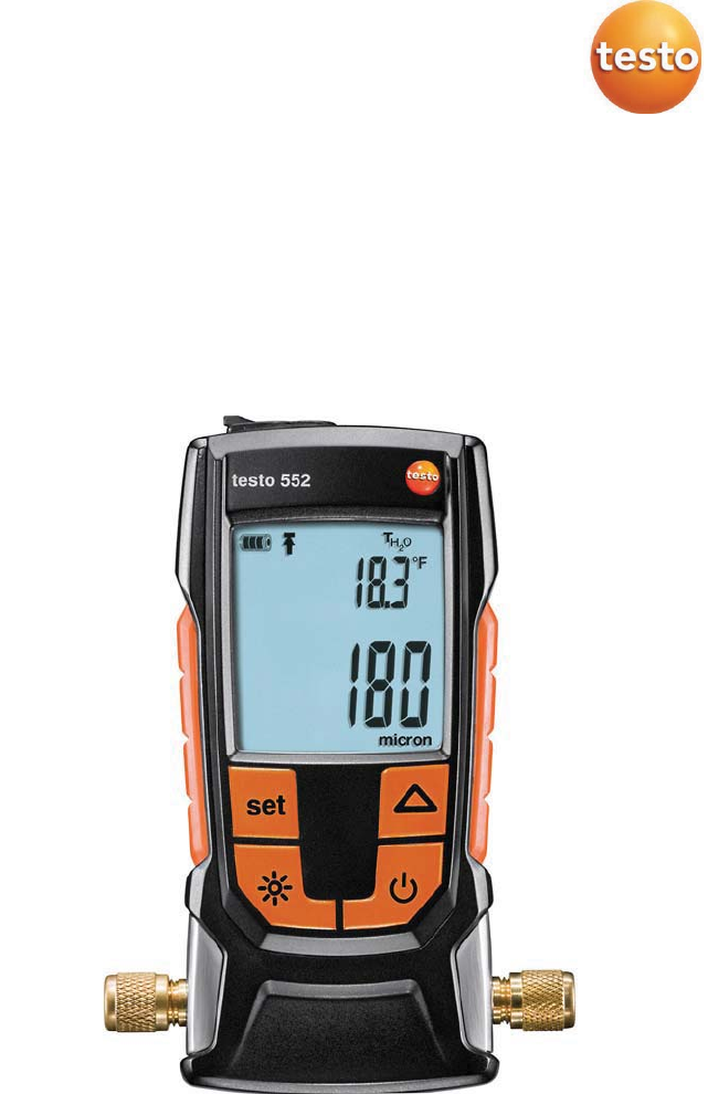
Testo 552 - Digital Vacuum Gauge with Bluetooth
Instruction manual

Content
Content
1
Safety and waste disposal ................................................................... 3
1.1 About this document .............................................................................. 3
1.2 Safety ..................................................................................................... 3
1.3 Waste disposal ....................................................................................... 4
2
General technical data ......................................................................... 4
2.1 Bluetooth module ................................................................................... 5
3
Description of the instrument ............................................................... 6
3.1 Use ......................................................................................................... 6
3.2 Instrument overview ............................................................................... 7
3.3 Displays overview................................................................................... 8
3.4 Control keys overview ............................................................................ 9
3.5 Connection options overview ................................................................. 9
4
Operation ........................................................................................... 11
4.1 Connecting ........................................................................................... 11
4.2 Switching instrument on and off .......................................................... 12
4.3 Switching background illumination on and off ..................................... 12
4.4 Setting units and AutoOff ..................................................................... 13
4.5 Displaying temperature values ............................................................. 15
4.6 Establishing a Bluetooth® connection ................................................. 16
4.7 1.1. Overview of operating controls ..................................................... 17
4.8 App options .......................................................................................... 17
4.8.1 Set “Language” ..................................................................... 17
4.8.2 Display Tutorial ...................................................................... 18
4.8.3 Display testo website ............................................................ 18
4.8.4 Display App Info .................................................................... 18
4.9 List, graphic diagram and table view ................................................... 18
4.10 Exporting readings ............................................................................... 19
4.10.1 Excel (CSV) Export ................................................................ 19
4.10.2 PDF Export ............................................................................ 19
4.10.3 Exporting a graph .................................................................. 20
4.11 Operating as a probe on the testo 570 ................................................ 20

Content
5
Maintenance ...................................................................................... 21
5.1 Changing batteries .............................................................................. 21
5.2 Cleaning the instrument ....................................................................... 22
6
Tips and assistance ........................................................................... 23
6.1 Questions and answers ....................................................................... 23
6.2 Accessories and spare parts ............................................................... 23
7
EC Declaration of Conformity ............................................................. 24

1
Safety and waste disposal
3
1
Safety and waste disposal
1.1
About this document
• The instruction manual is an integral part of the instrument.
• Keep this document throughout the entire operating life of the instrument.
• Always use the complete original instruction manual.
• Please read this instruction manual through carefully and familiarise
yourself with the product before putting it to use.
• Pay particular attention to the safety instructions and warning advice in
order to prevent injury and damage to the product.
1.2
Safety
General safety instructions
• Only operate this instrument in the proper manner, for its intended purpose
and within the parameters specified in the technical data.
• Do not apply any force to open the instrument.
• Do not operate the instrument if there are signs of damage at the housing,
mains unit or connected cables.
• Always comply with the locally valid safety regulations when carrying out
measurements. Dangers may also arise from objects to be measured or
the measuring environment.
• Do not store the product together with solvents.
• Do not use any desiccants.
• Only perform maintenance and repair work on this instrument that is
described in this documentation. Follow the prescribed steps exactly.
• Use only original spare parts from Testo.
Batteries
• Improper use of batteries may cause the batteries to be destroyed, or lead
to injury due to current surges, fire or escaping chemicals.
• Only use the batteries supplied in accordance with the instructions in the
instruction manual.
• Do not short-circuit the batteries.
• Do not take the batteries apart and do not modify them.
• Do not expose the batteries to heavy impacts, water, fire or temperatures
in excess of 60 °C.
2
General technical data
4
• Do not store the batteries in the proximity of metal objects.
• Do not use any leaky or damaged batteries.
• In the event of contact with battery acid: rinse affected areas thoroughly
with water, and if necessary consult a doctor.
• Take batteries out of the instrument immediately if they are not functioning
properly or if they show signs of overheating.
• Remove all batteries from the instrument if it is to remain unused for a
longer period.
Warnings
Always pay attention to any information denoted by the following warnings.
Implement the precautionary measures specified!
Display Explanation
WARNING
Indicates possible serious injury.
CAUTION
Indicates possible minor injury.
ATTENTION
Indicates possible damage to equipment.
1.3
Waste disposal
• Dispose of faulty rechargeable batteries and spent batteries in accordance
with the valid legal specifications.
• At the end of its useful life, dispose of the instrument via separate
collection for electro- and electronic devices. Please observe local
regulations concerning waste disposal. Or alternatively return the product
to Testo for disposal.
2
General technical data
Feature Values
Vacuum measuring range 0 to 26.66 mbar / 0 to 20,000 microns
Sensor overload (relative) 5 bar / 72 psi
Vacuum resolution 1 micron (from 0 to 1,000 microns)
10 microns (from 1,000 to 2,000 microns)
100 microns (from 2,000 to 5,000 microns)
500 microns (from 5,000 to 10,000 microns)
5,000 microns (from 10,000 to 20,000 microns
2
General technical data
5
Feature Values
Vacuum accuracy ±(10% of m.v. +10 microns) (100 to
1,000 microns)
Operating temperature -10 to 50 °C / 14 to 122 °F
Storage temperature -20 to 50 °C / -4 to 122 °F
Temperature measuring
range
-10 to 50 °C / 14 to 122 °F
Temperature resolution 0.1 °C / 0.1 °F
Battery life 50 h (without background illumination and
Bluetooth)
Protection class IP 42
Parameter mmHG, Torr, mbar, hPa, micron, inH2O, inHg.
Pa
Measuring cycle 0.5 sec
Sensor 1× Pirani sensor
Connections - 2× 7/16" UNF
- 1x MiniDIN (t570)
Warranty 2 years
Warranty terms: see website
www.testo.com/warranty
Setting values alarm treshold
Unit Setting range Resolution
mbar / hPa 0 - 7,5 0,05
micron 0 - 7500 50
2.1
Bluetooth module
The use of the wireless module is subject to the regulations and
stipulations of the respective country of use, and the module may only
be used in each case in countries for which a country certification has
been granted.
The user and every owner undertake to adhere to these regulations and
prerequisites for use, and acknowledge that the re-sale, export, import,
etc. in particular in, to or from countries without wireless permits, is
their responsibility.

3
Description of the instrument
6
Feature Value
Bluetooth Range 20 m (free field)
(Varies depending on the capability of the
mobile terminal device used.)
Bluetooth type LSD Science & Technology Co., Ltd
L series BLE module (08 May 2013) based on
TI CC254X chip
Qualified Design ID D030430
Bluetooth radio class Class 3
Bluetooth company 10274
3
Description of the instrument
3.1
Use
The testo 552 is a digital vacuum gauge for the precise measurement of
extremely small pressures in the vacuum range. This allows you to monitor the
evacuation (usually during commissioning) of refrigeration systems and heat
pumps.
With the testo 552, you can therefore measure the current pressure in a
refrigeration system, and thus gather information about the degree of
dehumidification and the removal of foreign matter (oils, foreign gases, etc.).
A vacuum gauge is always used in conjunction with a vacuum pump (generates
the vacuum). A manifold (analogue or digital) is also often used in order to
obtain controlled access to the refrigeration system.
3
Description of the instrument
7
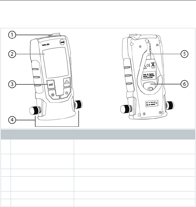
3.2
Instrument overview
Element Function
1
MiniDIN probe socket Cable connection for connecting to the testo
570.
2
Display Displays instrument status icons, measuring
units and measuring values.
3
Control keys Instrument operation.
4
Connections 7/16"
UNF, brass
Connection of refrigerant hoses, vacuum pump,
manifolds, etc..
5
Hook Suspension device
6
Battery compartment Contains two AA batteries.
3
Description of the instrument
8
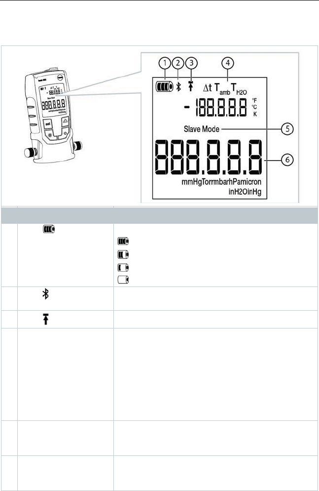
3.3
Displays overview
Element Function
1
Icon [ ] Displays the remaining battery capacity.
>75%
>50%
>25%
<10%
2
Icon [ ] Bluetooth® appears when Bluetooth has been
activated on the instrument.
3
Icon [ ] An alarm threshold is set.
4
Temperature display - selected, currently measured temperature
- Measurement parameter:
T
H2O
= evaporation temperature of water
T
amb
= ambient temperature
Δt = temperature difference between
evaporation temperature of water and ambient
temperature
- unit set (°C, °F)
5
Slave Mode Appears when the testo 552 is connected to the
testo 570 via a connecting cable and the
testo 570 is in
Evacuation
mode.
6
Pressure display Displays the currently measured pressure, the
measurement parameter and the unit set (mmHG,
Torr, mbar, hPa, micron, inH2O, inHg).
3
Description of the instrument
9
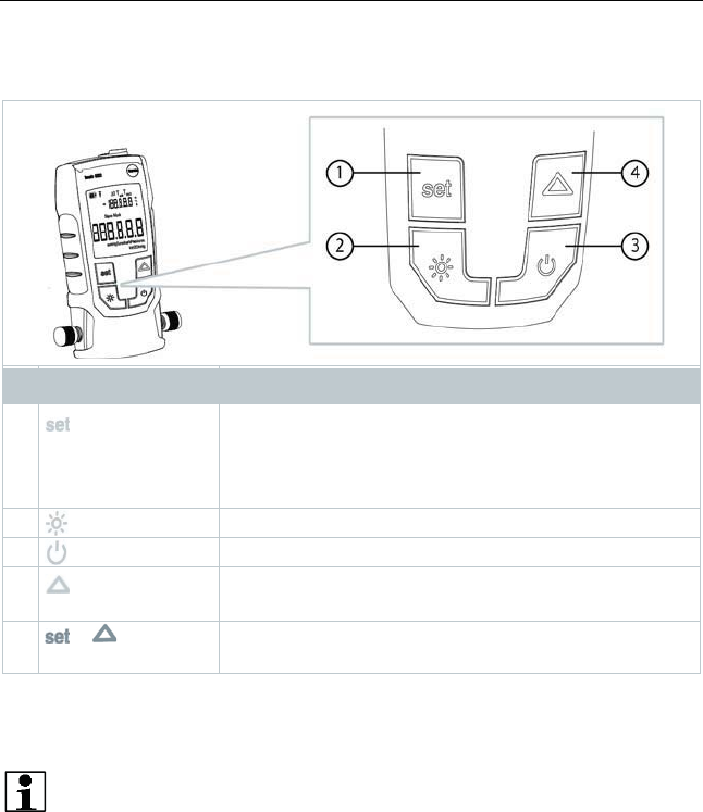
3.4
Control keys overview
Element Function
1
- Switches to the settings.
- Switches between the set-up options.
(This function is disabled, when connected to the
App with BT)
2
Switches the display illumination on or off.
3
Switches the instrument on or off.
4
- Switches between the temperature displays.
- Navigates in the Set menu.
5
+ Switches Bluetooth® on or off (press and hold down
for 3 sec.)
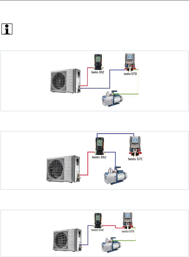
3.5
Connection options overview
In regard to the following connection options, the testo 570 is used to
represent any manifold and can use the testo 552 as a probe via a
MiniDIN connecting cable (see Option 2).
3
Description of the instrument
10
Option 1 (recommended)
The testo 552 is connected at the point that is furthest from the
vacuum pump. This ensures that a sufficiently deep vacuum is
generated throughout the system in order to remove any moisture or
foreign gases that may be present.
Option 2
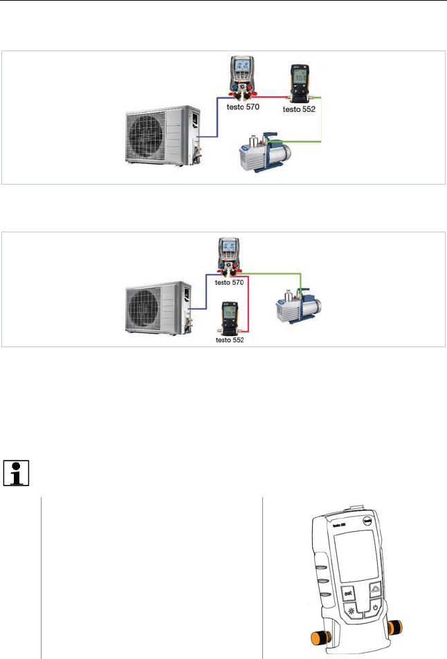
Option 3
4
Operation
11
Option 4
Option 5
4
Operation
4.1
Connecting
Always use refrigerant hoses that are specifically intended for
evacuations.
1
- Remove sealing caps.
- Connect the testo 552 to the circuit.
4
Operation
12
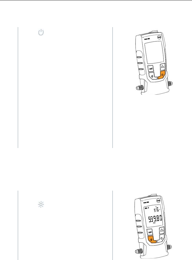
4.2
Switching instrument on and off
1
- Press .
Ì
The instrument switches on or off.
Ì
The instrument displays oooooo
when ambient pressure is applied to
the connections. The display
indicates the applied pressure value
once the applied pressure is within
the measuring range. (0 to 20,000
microns).
4.3
Switching background illumination on
and off
1
- Switch the instrument on.
- Press .
Ì
The background illumination switches
on or off.
4
Operation
13
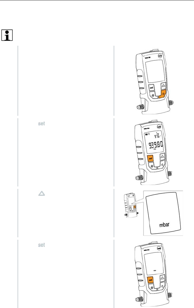
4.4
Setting units and AutoOff
The set-up menu must always be completely navigated through, even
if only one parameter needs to be changed.
1
- Switch the instrument on.
2
- Press to change settings.
3
- Press to set the pressure unit
required.
4
- Press .
Ì
The unit is set.
Ì
The display shows the temperature
unit.

4
Operation
14
5
- Press to set the temperature unit
required.
6
- Press .
Ì
The temperature unit is set.
Ì
The display shows the setting for the
alarm threshold.
Adjusting the alarm threshold causes an alarm to be triggered when
the set value is exceeded.
7
- Press to set the alarm threshold.
8
- Press .
Ì
The alarm threshold is set.
Ì
The display shows the AutoOff
setting.
If AutoOff is activated, the instrument switches off after 15 minutes
when ambient pressure is applied to the sensor.
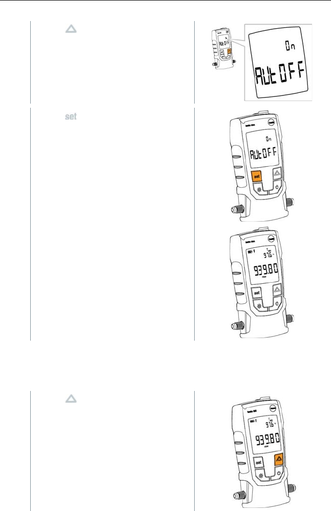
4
Operation
15
9
- Press to switch AutoOff on or off.
10
- Press .
Ì
All settings are stored.
Ì
The display changes to the measuring
mode.
Ì
The instrument can now be used.
4.5
Displaying temperature values
1
- Press to change the temperature
measurement parameter.
4
Operation
16
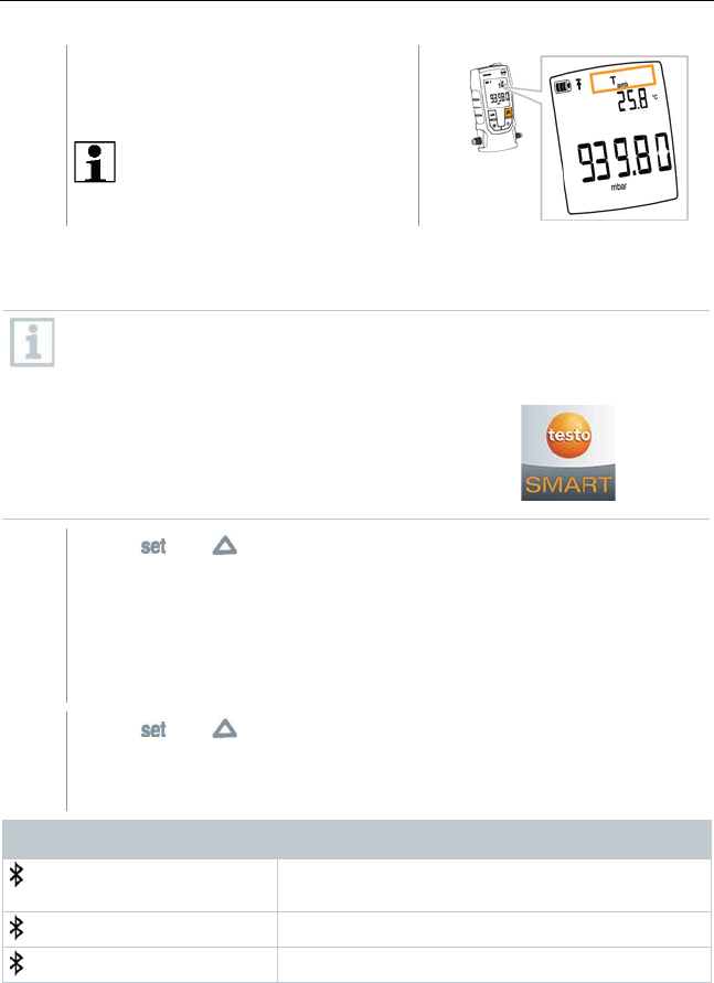
Ì
The temperature measurement
parameter switches between TH2O,
Tamb and t.
t is displayed in K for °C, and
in °F for °F.
4.6
Establishing a Bluetooth® connection
You need a tablet or smartphone with the Testo Smart Probes App
already installed on it to be able to establish a Bluetooth connection.
You can get the App for iOS instruments in the App Store or for
Android instruments in the Play Store.
Compatibility:
Requires iOS 8.3 or later / Android 4.3 or later
Requires Bluetooth 4.0
1
- Press and simultaneously and hold down for 3 seconds.
Ì
- When the Bluetooth icon is shown on the display, Bluetooth is
switched on.
- Once the APP is opened, the instrument will be connected
automatically if it is within range. The instrument does not have to
be connected to the smartphone / tablet beforehand via settings.
2
- Press and simultaneously and hold down for 3 seconds.
Ì
- When the Bluetooth icon is no longer shown on the display,
Bluetooth is switched off.
Display Explanation
flashes There is no Bluetooth® connection, or a
potential connection is being searched for.
is permanently displayed There is a Bluetooth® connection
is not displayed Bluetooth® is disabled.
4
Operation
17
4.7
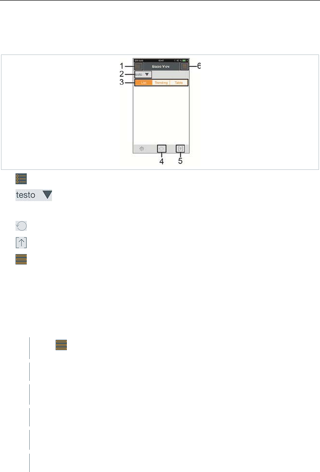
1.1. Overview of operating controls
1. Choice of applications.
2. Display of connected testo 552.
3. Switch between the views (list, graphic diagram, table).
4. Restarts the measuring value recording in graph and table format.
5. Export the readings.
6. Options menu.
4.8
App options
4.8.1
Set “Language”
1
- Tap -> Settings -> Language
Ì
A selection list is displayed.
2
- Tap the required language.
Ì
The selected language receives a green check mark.
3
- Tap several times until the measurement view is displayed.
Ì
The language has been changed.

4
Operation
18
4.8.2
Display Tutorial
The Tutorial guides you through the first steps when operating the testo
Smart Probes App.
1
- Tap -> Tutorial
Ì
The Tutorial is displayed. In Tutorial, swipe to display the next page.
2
- Tap X to close the Tutorial.
4.8.3
Display testo website
An internet connection is required to display the testo website.
1
- Tap -> About/Link -> Testo
Ì
The page www.testo-international.com is displayed.
4.8.4
Display App Info
In App Info you can find the version number of the installed App.
1
- Tap -> About/Link -> Info
Ì
The App’s version number is displayed, as well as the ID.
2
- Tap several times until the measurement view is displayed.
4.9
List, graphic diagram and table view
The available readings can be displayed in different ways in the various views.
• List view
Displays the readings transmitted by the testo 552 in the form of a list.
Readings from all connected testo 552 are displayed here.
• Graphic diagram view
The graphical progression of up to four different readings can be displayed.
Tap on a reading above the diagram to select the readings to be displayed.

4
Operation
19
• Table view
In the Table view, all readings are displayed in sequence according to date
and time. The different readings from the individual testo 552 can be
selected by pressing Ż Ź.
4.10
Exporting readings
4.10.1
Excel (CSV) Export
1
- Press .
Ì
A selection of export options appears.
2
- Press Export Excel (CSV).
Ì
A list of readings is displayed.
3
- Press .
Ì
A selection of sending/export options appears.
4
- Select your required sending/export options.
4.10.2
PDF Export
1
- Press .
Ì
A selection of export options appears.
2
- Press Export PDF.
Ì
A PDF is created and saved on your mobile terminal device (Android
only) or sent via e-mail (iOS and Android).
3
- Press Done to exit the detailed view.

4
Operation
20
4.10.3
Exporting a graph
1
- Press .
Ì
A selection of export options appears.
2
- Press Export Graph.
Ì
An image file of the trend display is created.
3
- Press .
Ì
A selection of sending/export options is displayed.
4
- Tap on the sending/export option you need
4.11
Operating as a probe on the testo 570
The testo 552 has no save or transmission function of its own.
By connecting the testo 552 to the testo 570, the data is transferred to the
testo 570. From there the data can be saved or managed via the EasyKool
software.
In combination with the testo 570, the testo 552 can be used as a high
precision vacuum probe, if connected to the front of the testo 570
using the connection cable 0554 5520. The firmware version 1.09 or
later must be installed for this.
Before connecting both instruments, the testo 552 must be switched
on and the same pressure unit must be set on both instruments.
The testo 570 will only connect to the testo 552 once the Evacuation
mode has been activated. When used as a probe, the testo 552 cannot
be operated, all keys are deactivated.
In order to be able to use the readings from the testo 552 via the testo
570 in the EasyKool software, you need EasyKool software version 4.0
or later.
5
Maintenance
21
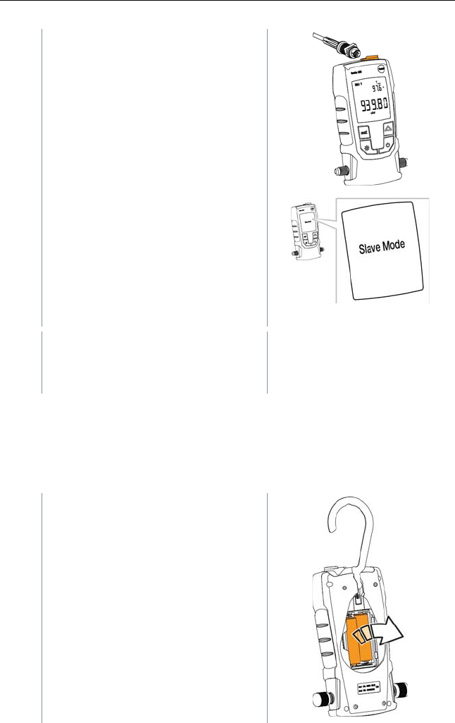
1
- Connect the connecting cable to the
MiniDIN probe socket of the testo
552.
2
- Connect the connecting cable to the
front-end MiniDIN probe socket of
the testo 570.
3
- On the testo 570 set Evacuation
mode.
Ì
The testo 552 switches to Slave
mode.
Ì
The keys of the testo 552 are
deactivated.
Ì
The readings are transmitted to the
testo 570.
4
- Remove the connecting cable.
Ì
The testo 552 exits Slave mode.
5
Maintenance
5.1
Changing batteries
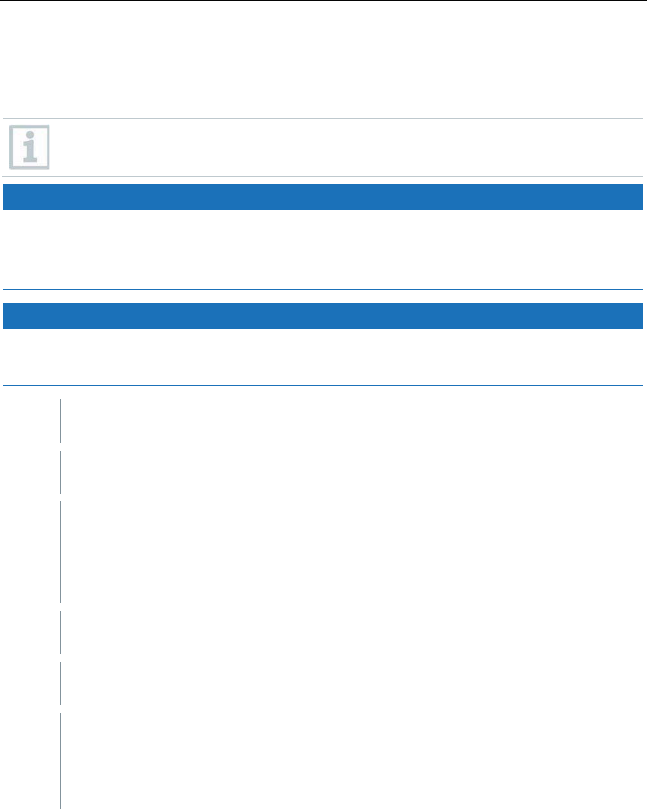
1
- Switch the instrument off.
2
- Flip hook up.
3
- Open the battery compartment.
4
- Remove batteries.
5
- Insert new batteries, observing the
indications inside the battery
compartment.
6
- Close the battery compartment.
7
- Fold hook down.
5
Maintenance
22
5.2
Cleaning the instrument
Contaminants such as oil may impair the accuracy of the vacuum
sensor. Complete the following steps to clean the sensor.
CAUTION
Carrying out cleaning with the instrument switched on may result in
damage to the sensor!
-
Before cleaning, switch the instrument off!
CAUTION
Damage to the sensor due to sharp objects!
-
Do not insert any sharp objects into the connections!
1
- Switch the instrument off.
2
- Put a few drops of rubbing alcohol into one of the two connections.
3
- Seal the opening by placing your finger on it or screw on the sealing
caps.
- Shake the instrument briefly.
4
- Remove all the alcohol from the instrument.
5
- Repeat this process at least twice.
6
- Leave the instrument to dry for at least 1 hour. To dry the sensor
faster, you can connect the probe directly to a vacuum pump and
draw vacuum.

6
Tips and assistance
23
6
Tips and assistance
6.1
Questions and answers
Question Possible cause / solution
Readings are incorrect. - Check that the testo 552 is connected
properly.
- Connect the testo 552 directly to the
vacuum pump in order to check the values.
- Check that all hoses are leak-tight.
- Clean the sensor as described in the
Cleaning the instrument
section.
Instrument displays oooooo The applied pressure is outside the specified
measuring range. (0 to 20,000 microns).
If we have not been able to answer your question, please contact your dealer or
Testo Customer Service. You will find contact details on the back of this
document or on the website
www.testo.com/service-contact
6.2
Accessories and spare parts
Description Item no.
Connecting cable for testo 552 0554 5520
7
EC Declaration of Conformity
24
7
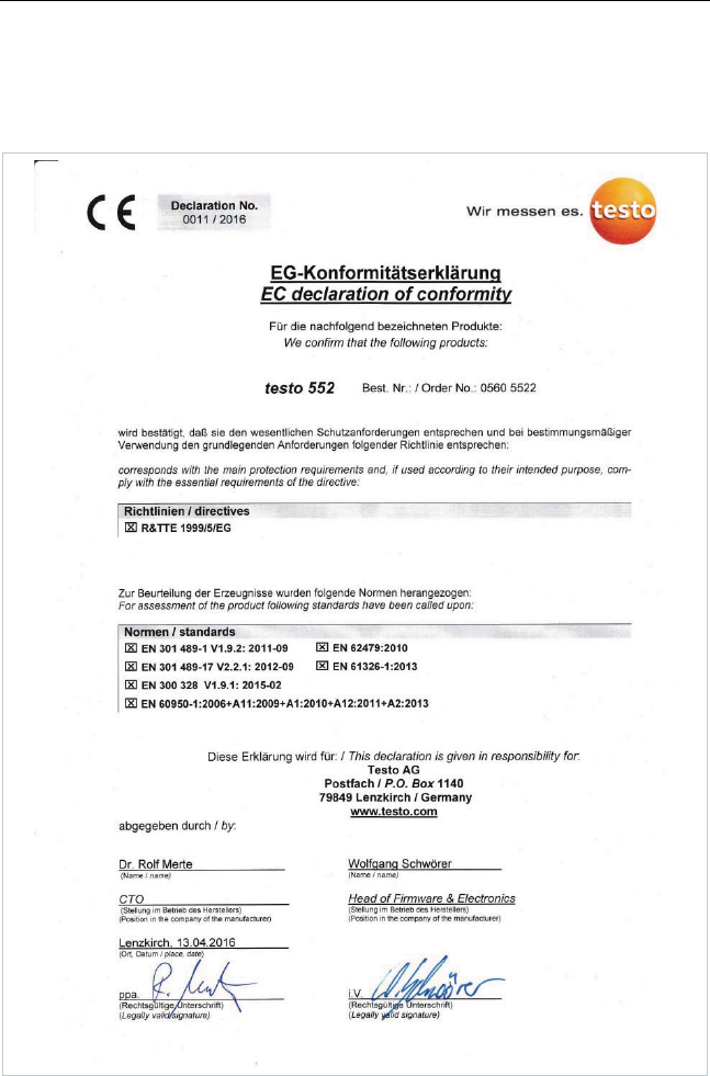
EC Declaration of Conformity
7
EC Declaration of Conformity
25
The use of the wireless module is subject to the regulations and stipulations
of the respective country of use, and the module may only be used in countries
for which a country certification has been granted. The user and every owner
has the obligation to adhere to these regulations and prerequisites for use, and
acknowledges that the re-sale, export, import etc. in particular in countries
without wireless permits, is his responsibility.
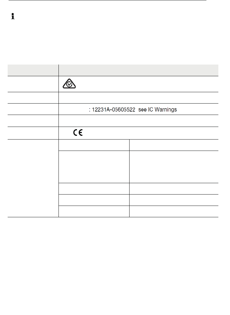
Country Comments
Australia E1561
Turkey Authorized
Canada Product IC ID: 12231A-05605522 see IC Warnings
USA Product FCC ID: 2ACVD05605522 see FCC Warnings
Europe + EFTA See - declaration of conformity
Bluetooth SIG
Listing
Bluetooth® Range >20 m (free field)
Bluetooth® type LSD Science & Technology Co.,
Ltd, L Series BLE Module (08
Mai 2013) based on TI CC254X
chip
Qualified Design ID D030430
Bluetooth® radio class Class 3
Bluetooth® company ID 10274
FCC Warnings
Information from the FCC (Federal Communications Commission)
For your own safety
Shielded cables should be used for a composite interface. This is to ensure
continued protection against radio frequency interference.
FCC warning statement
This equipment has been tested and found to comply with the limits for a Class
C digital device, pursuant to Part 15 of the FCC Rules. These limits are
designed to provide reasonable protection against harmful interference in a
residential installation. This equipment generates, uses and can radiate radio
The device has been evaluated to meet general RF exposure requirement, The device
can be used in portable exposure condition without restriction
This device complies with part 15 of the FCC rules. Operation is subject to the
following two conditions: (1) this device may not cause harmful interference, and (2)
this device must accept any interference received, including interference that may
cause undesired operation.
NOTE: The manufacturer is not responsible for any radio or TV interference caused
by unauthorized modifications or changes to this equipment. Such modifications or
changes could void the user’s authority to operate the equipment.
NOTE: This equipment has been tested and found to comply with the limits for a
Class B digital device, pursuant to part 15 of the FCC Rules. These limits are designed
to provide reasonable protection against harmful interference in a residential
installation. This equipment generates uses and can radiate radio frequency energy
and, if not installed and used in accordance with the instructions, may cause harmful
interference to radio communications. However, there is no guarantee that
interference will not occur in a particular installation. If this equipment does cause
harmful interference to radio or television reception, which can be determined by
turning the equipment off and on, the user is encouraged to try to correct the
interference by one or more of the following measures:
- Reorient or relocate the receiving antenna.
- Increase the separation between the equipment and receiver.
-Connect the equipment into an outlet on a circuit different from that to which the
receiver is connected.
-Consult the dealer or an experienced radio/TV technician for help.
This device complies with Industry Canada license-exempt RSS standard(s).
Operation is subject to the following two conditions:
(1) this device may not cause interference, and
(2) this device must accept any interference, including interference that may
cause undesired operation of the device.
Cet appareil est conforme avec Industrie Canada RSS exemptes de licence standard(s).
Son fonctionnement est soumis aux deux conditions suivantes:
(1) cet appareil ne peut pas provoquer d'interférences, et
(2) cet appareil doit accepter toute interférence, y compris celles pouvant causer un
mauvais fonctionnement de l'appareil.