Trane Cgprc007en1 CG DS 1 (3/99) 10 60 Ton Air Cooled Chillers Data Catalog User Manual 32f85bf8 326c 412c 8ab0 44449f4dee7a
User Manual: trane cgprc007en1 Trane Air Conditioner CG-PRC007-EN User Guide |
Open the PDF directly: View PDF ![]() .
.
Page Count: 52
Air-Cooled
Liquid Chillers
10 to 60 Tons
CG-PRC007-EN
March 2003
© 2003 American Standard Inc. All rights reserved CG-PRC007-EN
Introduction
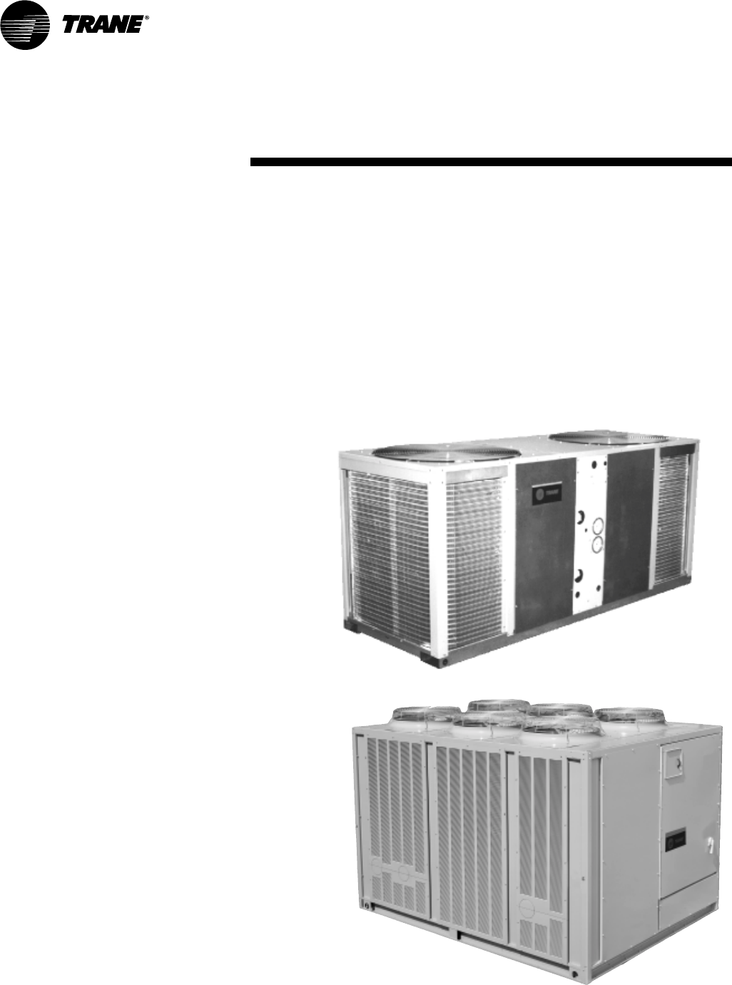
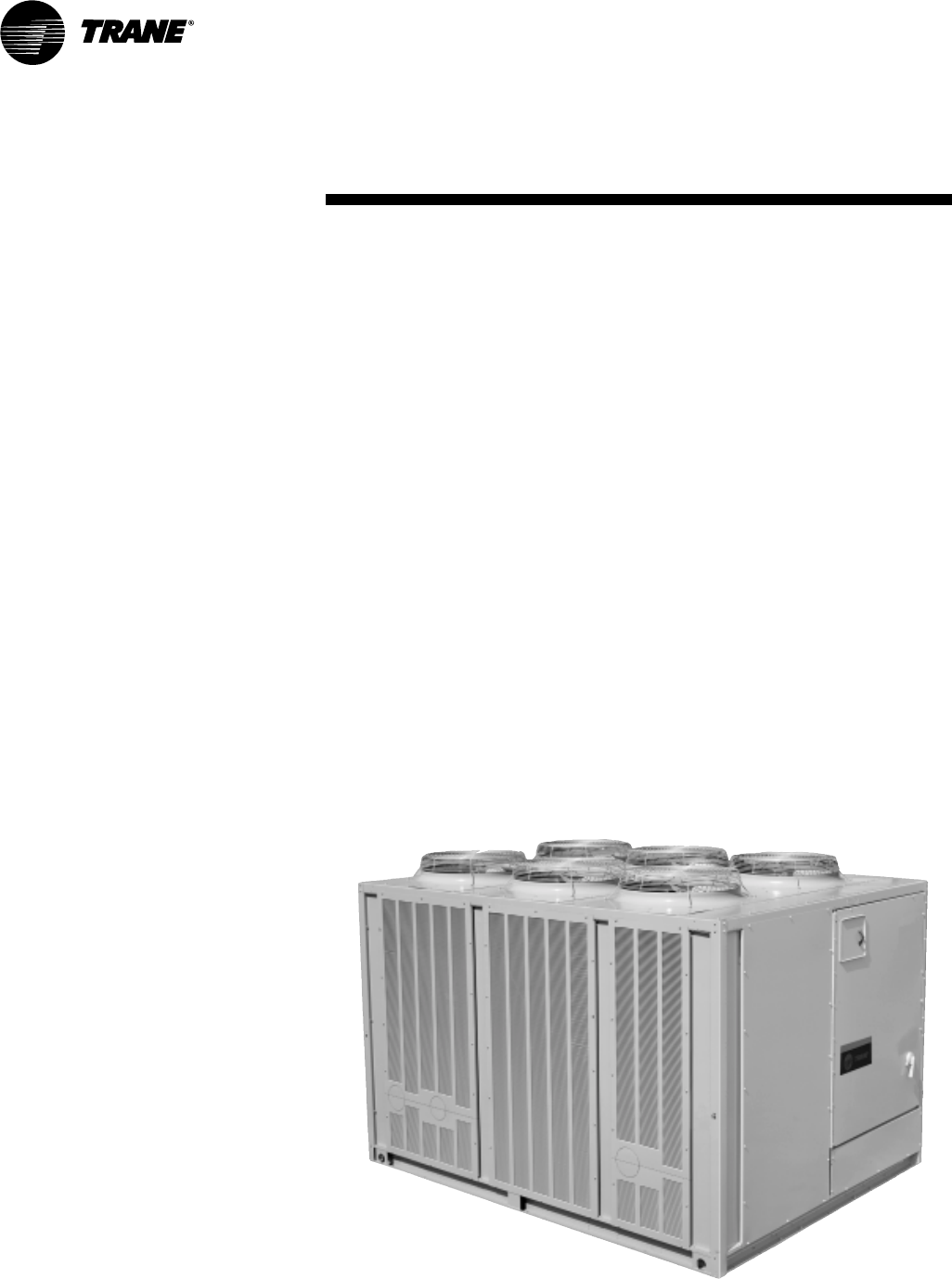
Air-Cooled
Liquid Chillers
10, 15 Tons
20–60 Tons
Design and manufacturing excellence
makes Trane a leader in the air-cooled
chiller marketplace. For over 40 years,
Trane has been using the best
engineering available in development,
manufacturing, and marketing to
produce quality products. This tradition
of using excellence to meet market
demands is illustrated with the Trane 10
to 60-ton air-cooled chillers.
CG-PRC007-EN4
Features and
Benefits
Installation
Small size, complete factory wiring, easy
lifting provisions, factory installed
options and start-up control provide fast,
easy installation. A complete factory run
test is performed on each unit,
eliminating potential start-up problems.
Integrated Comfort Systems
All Trane chillers are ICS compatible. A
simple twisted wire pair is all it takes to
hook an air-cooled chiller into a Tracer
system. An ICS system provides the
most advanced diagnostics, monitoring,
and control that the industry can offer.
Only Trane can supply the entire package.
ICS provides comfort with one word —
Trane.
Packed Stock Increases
Project Flexibility
Trane 10 to 60-ton air-cooled chillers
are available through the most flexible
packed stock program in the industry.
Trane knows you want your units on
the jobsite, on time, when you need
them. To help meet this demand, Trane
keeps a multitude of unit sizes and
voltages in packed stock. Many of
these include optional features such as
isolators, low ambient head pressure
controls and refrigerant gauge piping.
You no longer have to settle for a
scaled-down, basic unit to meet your
job schedule. In many cases, units can
be shipped directly to the jobsite from
packed stock!
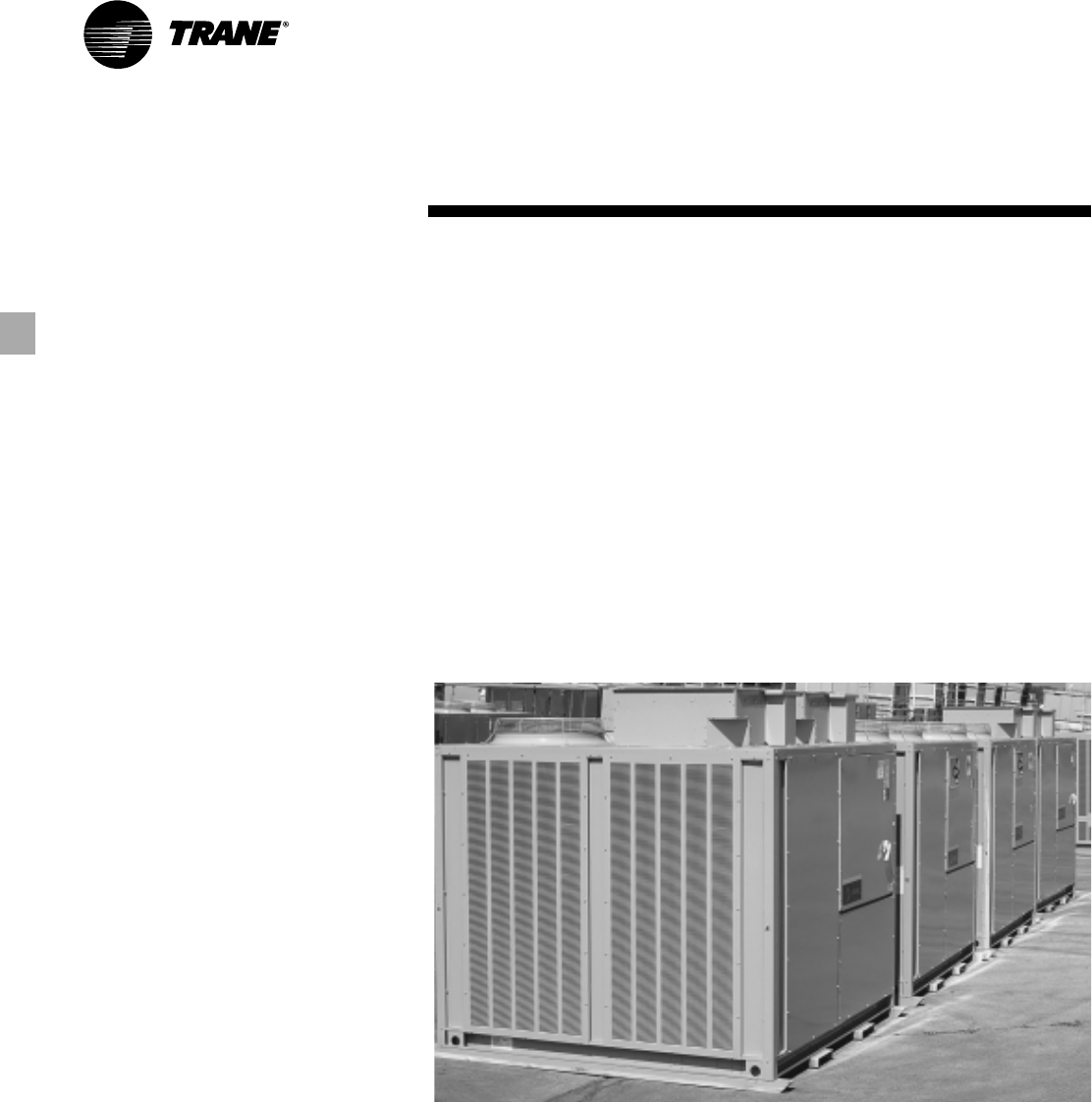
(10–60 Ton)
5CG-PRC007-EN
Features and
Benefits
The 10 and 15-ton air-cooled Cold
Generator™ chillers, with Trane direct
drive hermetic scroll compressors, has
outstanding standard features and
additional benefits that make selection,
installation, and servicing easy.
Flexibility
Footprint
Central to the design of any project is the
operating envelope of the air-cooled
packaged chiller. With this in mind, Trane
builds the chillers to make the most
efficient use of the available installation
space. The Trane CGA model chillers are
extremely compact. They have the
lightest weight, the smallest footprint,
and the lowest silhouette of any chiller in
the industry.
Less Weight
These lightweight models afford less
stress on building supports and greater
handling ease.
Installation
Installation time and effort are reduced
when dealing with a significantly smaller
and lighter unit. In addition, having
electrical and water connections on the
same side of the unit and a single-point
main power connection serves to make
installation easier. The unit arrives at the
jobsite fully assembled, tested, charged
and ready to provide chilled water.
Ease of Service
The control panel and unit panels are
completely removable for service
accessibility and convenience.
ICS Interface
Communication with Trane Tracer™ or
Tracker™ is possible through the ICS
Interface on the 10 and 15 ton Cold
Generator chiller.
Optional Features
•Hot Gas Bypass — Allows unit
operation below the minimum step of
unloading.
•Low Ambient Head Pressure Control
— Modulates the rpm of the fan motor
in response to outdoor ambient
temperature and unit head pressure.
Provides unit cooling operation down
to outdoor temperatures of 0°F.
•Coil Guard — Metal grille with PVC
coating to protect the condenser coil.
•Isolation — Neoprene in shear or
spring flex isolators.
•Power Supply Monitor — Provides
protection against phase loss, phase
reversal, phase imbalance, incorrect
phase sequence and low line voltage.
•Elapsed Time Meter/Number Starts
Counter — Records number of
compressor starts and operating
hours.
•Flow Switch — Required as a safety
interlock to prevent operation of unit
without evaporator flow (available
option for field installation only).
•Integrated Comfort Systems (ICS)
Interface — Provides the ability to
communicate with Trane Tracer or
Tracker building management systems
via a Thermostat Control Module —
(TCM).
•Gauges — Monitor suction and
discharge pressures.
(10–15 Ton)
CG-PRC007-EN6
Features and
Benefits
(20–60 Ton)
Other Standard Features
•Trane 3-D Scroll compressors
•Advanced motor protection
•300 psi waterside evaporator
•Evaporator insulation (¾-inch
Armaflex II or equivalent)
•Evaporator heat tape (thermostat
controlled)
•Condenser coil guards
•Operation down to 30°F without
additional wind baffles or head
pressure control
•Loss of flow protection
•UL and CSA approval available
•Packed stock availability
•Control Power Transformer
•Low ambient lockout
•Plain English (Spanish/French)
Human Interface display
•Smart Lead/Lag operation
•Integrated chilled solution pump
control
•Selectable process or comfort control
algorithm
•External auto/stop
•Electronic low ambient damper
control integrated into UCM
•Flow switch
•Strainer/connection kit
Trane’s 20-60 ton chillers offer the same
time-tested and proven control
technology that is applied to the
IntelliPak Air Cooled rooftops.
Superior control makes the IntelliPak a
truly advanced chiller.
Standard Features
Microprocessor Control
The IntelliPak chiller’s Unit Control
Module (UCM) is an innovative,
modular microprocessor control
design. It coordinates the actions of the
chiller in an efficient manner and
provides stand-alone operation of the
unit. A Human Interface (HI) Panel is a
standard component of the IntelliPak
Chiller. Access to all unit controls is via
the Human Interface Panel.
Factory Run Testing
In addition to outstanding efficient
performance, IntelliPak Chillers have
established a reputation for reliable
operation. Aside from the individual
component tests, all Trane 20 to 60-ton
chillers are factory run tested with
water running through the evaporator
to confirm proper operation. Control
operation and current draw are both
monitored to assure safe, reliable
operation.
Optional Features
•Controls for ice making operation
Miscellaneous Options
•Trane Communications Interface
Module (TCI)
•Unit Mounted Disconnect
•Isolators
•Superheat/Sub-Cooling Module
•Hot Gas Bypass
•Generic B A S Modules with 0-10 v
analog input/output, 0-5 v analog
input/binary output
•Remote Human Interface Panel
(RHI)
•Remote Set point Potentiometer
•Zone Sensor (Chilled Solution
Reset)
•Copper Fin Condenser Coils
•Electronic Low Ambient Damper(s)
•Inter-Processor Communication
Bridge (IPCB)
•Ice building control
•Other options
In addition to all of these options, Trane
can offer in-house design for many
applications, including special coil
coating.
7CG-PRC007-EN
Features and
Benefits
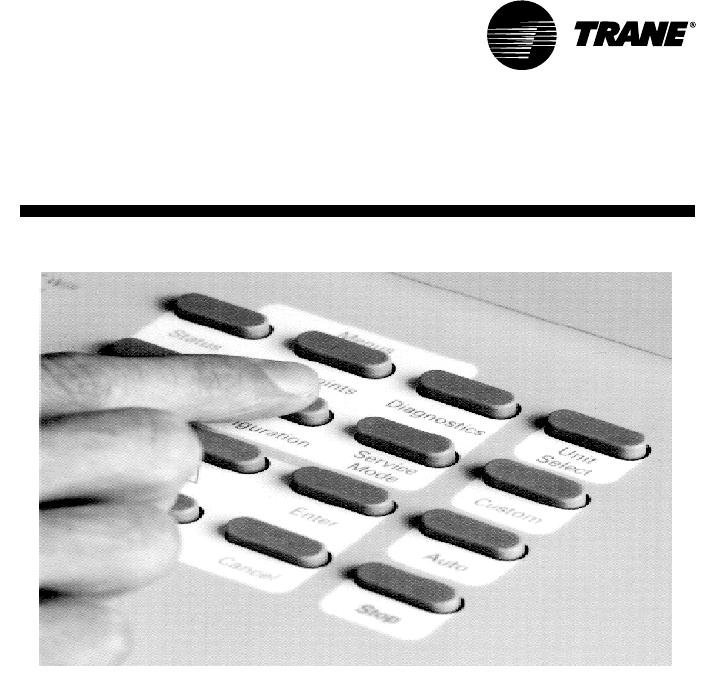
Enhanced Controls
IntelliPak Chiller Unit Control Module
(UCM)
Microprocessor Control
The brain of the 20 to 60 ton air-cooled
chiller is its Unit Control Module (UCM).
The UCM is an innovative, modular
microprocessor control design, which
coordinates the actions of the chiller in
an efficient manner, providing stand-
alone operation of the unit.
Access to the unit controls is via a
Human Interface (HI) Panel, a standard
component of the IntelliPak chiller. This
panel provides a high degree of control.
Superior monitoring capability and
unmatched diagnostic information is
provided through a 2 line 40 character
per line, English language display.
There are no diagnostic “codes”
requiring a translation key for
interpretation. All system status
information and control adjustments
can be made from the onboard Human
Interface Panel.
The Integrated Comfort™ System — The Industry’s Most Advanced Comfort System
ICS gives you the most powerful
monitoring and diagnostic system
available. Monitoring up to 30 individual
points, the ICS can detect and correct
problems before a comfort level change
is even noticed. Advanced monitoring
and diagnostics can help building
owners to more effectively market their
buildings to prospective tenants.
An ICS system is the most advanced
comfort system in the industry. Because
Trane has more experience with ICS
than all other equipment manufacturers
combined, you can feel secure knowing
that you are dealing with a proven track
record in building management. Trane is
the only brand that supplies the entire
package.
The UCM allows the 20 to 60-ton
IntelliPak chiller to be part of the factory
installed Integrated Comfort System
(ICS). ICS joins the Trane Tracer building
management systems and Trane HVAC
equipment by a single twisted wire
pair. This allows bidirectional
communication between the Tracer
system and the unit mounted controls.
Connected to the chiller’s UCM, this
simple pair allows you to control,
monitor, and diagnose your building’s
comfort system. The UCM is linked to
the Tracer system and they
electronically “talk” to one another.
Since ICS is factory-packaged, there is
no need to install separate sensors to
monitor your chiller’s operation. All of
the control points are on the controller
and ready to go when the unit ships.
Simply hookup the Tracer system to the
IntelliPak chiller with the twisted wire
pair. This feature means lower installed
cost, less chance for jobsite errors, less
design time on the front end of your
project, and fewer callbacks.
Tracer control points for
IntelliPak Chillers
•Chilled solution set point
•Default chilled solution set point
• Ice set point
• Default ice set point
•Chiller enable point
•Failure mode
•Ice making enable point
•KW limit enable point
•Demand limiting cooling stages
•Default number of compressors
•Design delta temperature
•Control response set point
• Reset option
Remote Human Interface (RHI) — The optional Remote Human Interface (RHI)
performs the same functions as the Human Interface, with the exception of the
service mode. The RHI can be used with up to 4 air-cooled chillers from a single
panel.
(20–60 Ton)
CG-PRC007-EN8
Features and
Benefits
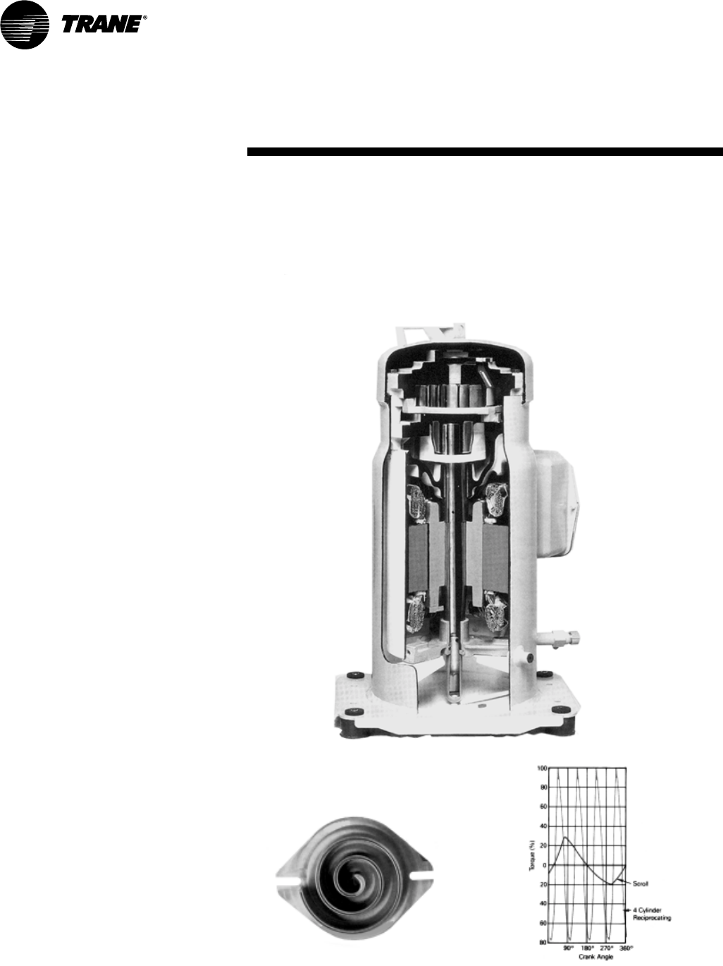
Trane 3-D Scroll Compressor
Simple Design with 70% Fewer Parts
Fewer parts than an equal capacity
reciprocating compressor means
significant reliability and efficiency
benefits. The single orbiting scroll
eliminates the need for pistons,
connecting rods, wrist pins and valves.
Fewer parts lead to increased reliability.
Fewer moving parts, less rotating mass
and less internal friction means greater
efficiency than reciprocating
compressors.
The Trane 3-D Scroll provides important
reliability and efficiency benefits. The 3-D
Scroll allows the orbiting scrolls to touch
in all three dimensions, forming a
completely enclosed compression
chamber which leads to increased
efficiency. In addition, the orbiting scrolls
only touch with enough force to create a
seal; there is no wear between the scroll
plates. The fixed and orbiting scrolls are
made of high strength cast iron which
results in less thermal distortion, less
leakage, and higher efficiencies. The
most outstanding feature of the 3-D
Scroll compressor is that slugging will
not cause failure. In a reciprocating
compressor, however, the liquid or dirt
can cause serious damage.
Low Torque Variation
The 3-D Scroll compressor has a very
smooth compression cycle; torque
variations are only 30 percent of that
produced by a reciprocating compressor.
This means that the scroll compressor
imposes very little stress on the motor
resulting in greater reliability. Low torque
variation reduces noise and vibration.
Suction Gas Cooled Motor
Compressor motor efficiency and
reliability is further optimized with the
latest scroll design. Cool suction gas
keeps the motor cooler for longer life and
better efficiency.
One of two matched scroll plates —
the distinguishing feature of the scroll
compressor.
Chart illustrates low torque variation of
3-D Scroll compressor vs.
reciprocating compressor.
Proven Design Through Testing and
Research
With over twenty years of development
and testing, Trane 3-D Scroll
compressors have undergone more
than 400,000 hours of laboratory testing
and field operation. This work combined
with over 25 patents makes Trane the
worldwide leader in air conditioning
scroll compressor technology.
(20–60 Ton)
9CG-PRC007-EN
Application
Considerations
Certain application constraints should be
considered when sizing, selecting and
installing Trane air-cooled chiller s. Unit
and system reliability is often dependent
upon proper and complete compliance
with these considerations. Where the
application varies from the guidelines
presented, it should be reviewed with
your local Trane sales engineer.
Note: The terms water and solution are
used interchangeably in the following
paragraphs.
UNIT SIZING
Unit capacities are listed in the
“Performance Data” section.
Intentionally oversizing a unit to assure
adequate capacity is not recommended.
Erratic system operation and excessive
compressor cycling are often a direct
result of an oversized chiller. In addition,
an oversized unit is usually more
expensive to purchase, install, and
operate. If oversizing is desired, consider
using two units.
UNIT PLACEMENT
1
Setting The Unit
A base or foundation is not required if
the selected unit location is level and
strong enough to support the unit’s
operating weight (see “Weights” section
of this catalog).
For a detailed discussion of base and
foundation construction, refer to the
Trane Reciprocating Refrigeration
Manual. Manuals are available through
the local Trane office.
2
Isolation and Sound Emission
The most effective form of isolation is to
locate the unit away from any sound
sensitive area. Structurally transmitted
sound can be reduced by using spring
isolators. Spring isolators are generally
effective in reducing vibratory noise
generated by compressors, and
therefore, are recommended for sound
sensitive installations. An acoustical
engineer should always be consulted on
critical applications.
Debris, trash, supplies, etc., should not
be allowed to accumulate in the vicinity
of the air-cooled chiller. Supply air
movement may draw debris into the
condenser coil, blocking spaces between
coil fins and causing coil starvation.
Both warm air recirculation and coil
starvation cause reductions in unit
efficiency and capacity because of the
higher head pressures associated with
them. In addition, in more severe cases,
nuisance unit shutdowns will result from
excessive head pressures. Estimates of
the degree of efficiency and capacity
reduction in such situations can be
determined. Consult your local Trane
sales engineer.
Cross winds, those perpendicular to the
condenser, tend to aid efficient operation
in warmer ambient conditions, however,
they tend to be detrimental to operation
in lower ambients or when hot gas
bypass is used due to the accompanying
loss of adequate head pressure. As a
result, it is advisable to protect air-cooled
chillers from continuous direct winds
exceeding 10 miles per hour in low
ambient conditions.
Low Ambient Operation — 20-60 Ton
models — Human Interface
Recommendations
When the temperature outside is
subzero, who wants to be out there
monitoring or troubleshooting
diagnostics? Because we understand a
service technician’s reluctance to do this,
we recommend using a Remote Human
Interface (RHI) panel. The service
technician can troubleshoot and
diagnose in the comfort of a mechanical
room.
For maximum isolation effect, water lines
and electrical conduit should also be
isolated. Wall sleeves and rubber isolated
piping hangers can be used to reduce the
sound transmitted through water piping.
To reduce the sound transmitted through
electrical conduit, use flexible electrical
conduit.
State and local codes on sound
emissions should always be considered.
Since the environment in which a sound
source is located affects sound pressure,
unit placement must be carefully
evaluated. Sound pressure and sound
power levels for chillers are available on
request.
3
Servicing
Adequate clearance for evaporator and
compressor servicing should be
provided. Recommended minimum
space envelopes for servicing are located
in the dimensional data section and can
serve as a guideline for providing
adequate clearance. The minimum space
envelopes also allow for control panel
door swing and routing maintenance
requirements. Local code requirements
may take precedence.
4
Unit Location
a
General
Unobstructed flow of condenser air is
essential to maintain chiller capacity and
operating efficiency. When determining
unit placement, careful consideration
must be given to assure a sufficient flow
of air across the condenser heat transfer
surface. Two detrimental conditions are
possible and must be avoided: warm air
recirculation and coil starvation.
Warm air recirculation occurs when
discharge air from the condenser fans is
recycled back to the condenser coil inlet.
Coil starvation occurs when free airflow
to the condenser is restricted.
Condenser coils and fan discharge must
be kept free of snow or other
obstructions to permit adequate airflow
for satisfactory unit operation.
CG-PRC007-EN10
Application
Considerations
c
Provide Lateral Clearance
The condenser coil inlet must not be
obstructed. A unit installed closer than
the minimum recommended distance to
a wall or other vertical riser may
experience a combination of coil
starvation and warm air recirculation,
resulting in unit capacity and efficiency
reductions and possible excessive head
pressures.
The recommended lateral clearances are
depicted in the dimensional data section.
These are estimates and should be
reviewed with the local Trane sales
engineer at the jobsite.
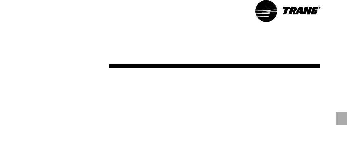
b
Provide Vertical Clearance
Vertical condenser air discharge must be
unobstructed. While it is difficult to
predict the degree of warm air
recirculation, a unit installed as shown
below would have its capacity and
efficiency significantly reduced —
possibly to the degree of nuisance high
head pressure trip outs. Performance
data is based on free air discharge.
d
Provide Sufficient Unit-to-Unit Clearance
Units should be separated from each
other by sufficient distance to prevent
warm air recirculation or coil starvation.
Doubling the recommended single unit
air-cooled chiller clearances will
generally prove to be adequate.
e
Walled Enclosure Installations
When the unit is placed in an enclosure
or small depression, the top of the fans
should be no lower than the top of the
enclosure or depression. If they are,
consideration should be given to ducting
the top of the unit. Ducting individual
fans, however, is not recommended.
Such applications should always be
reviewed with the local Trane sales
engineer.
VOLTAGE
Nominal voltage is the nameplate rating
voltage. The actual range of line voltages
at which the equipment can satisfactorily
operate are given below.
WATER TREATMENT
Dirt, scale, products of corrosion, and
other foreign material in the water will
adversely affect heat transfer between
the water and system components.
Foreign matter in the chilled water
system can also increase pressure drop
and, consequently, reduce waterflow.
Proper water treatment must be
determined locally and depends on the
type of system and local water
characteristics.
Do not use salt or brackish water in Trane
chillers. Use of either will lead to a
shortened life. Trane encourages the
employment of a reputable water
treatment specialist, familiar with local
water conditions, to assist in the
establishment of a proper water
treatment program.
The capacities given in the “Performance
Data” section of this catalog are based
on water with a fouling factor of 0.0001
(in accordance with ARI 550/590-98). For
capacities at other fouling factors, see
“Performance Adjustment Factors”
section of this catalog.
EFFECT OF ALTITUDE ON
CAPACITY
Chiller capacities given in the
“Performance Data” section are based
upon application at sea level. At
elevations substantially above sea level,
the decreased air density will decrease
condenser capacity and, therefore, unit
capacity and efficiency. The adjustment
factors in the “Performance Adjustment
Factors” section of this catalog can be
applied directly to the performance data
to determine the unit’s adjusted
performance.
Voltage
Rated Utilization
Voltage Range
200 180-220
208-230 187-253
230 208-254
380 342-418
400 360-440
415 374-456
460 414-508
575 520-635

11CG-PRC007-EN
CONTROLS
1
Temperature Controller
In order to provide stable system
operation and to prevent excessive
compressor cycling, the temperature
control sensor in all 20-60 ton chillers is
located in the supply (outlet) solution.
The temperature sensor in all 10 and 15
ton chillers is located in the return (inlet)
solution. This sensor cannot be
relocated. Doing so would result in
improper unit operation.
2
Anti-recycle Timer/Fixed-Off Timer
All IntelliPak air-cooled chillers come
standard with Anti-recycle/Fixed Off
Timers. This function prevents rapid
cycling of the compressors due to low
load conditions or short water loops.
3
Pumpdown
CGAF air-cooled chillers will pumpdown,
if function is enabled, when a refrigerant
circuit is turned off. All of the refrigerant
is pumped into the condenser. A
solenoid valve provides a positive shut
off between the condenser and the
evaporator, allowing little or no
refrigerant migration to the evaporator
during “off” periods.
4
Hot Gas Bypass
Hot gas bypass provides more stable
leaving solution temperature control at
light load conditions. The compressor
runs continuously for a user-defined run
time. Minimum starting and operating
ambients with hot gas bypass are shown
in the “General Data” section of this
catalog. The hot gas bypass reduces the
unit head pressure, thereby increasing
the minimum operating ambient.
5
Loss of Flow Protection
Loss of flow may result in evaporator
freeze up. Full chilled solution flow must
be maintained through the evaporator
while compressors are operating.
A flow switch used as a safety interlock is
always recommended for CGA units.
The CGAF air-cooled chiller has a system
which senses a loss of flow condition
and shuts the unit down. A flow switch
used as a safety interlock is required for
CGAF units. A set of contacts is available
for externally starting and stopping the
pump.
WATERFLOW LIMITS
The minimum water flow rates are given
in the “General Data” section of this
catalog. Evaporator flow rates below the
tabulated values will result in laminar
flow causing scaling, stratification,
freeze-up problems, and poor
temperature control.
The maximum evaporator water flow
rate is given in the “General Data”
section. Flow rates exceeding those
listed will result in excessive tube
erosion and very high pressure drop
across the evaporator.
Trane recommends that constant water
flow be maintained at all times through
the evaporator. Because the
temperature controller strictly senses
temperature, variable flow through the
evaporator may result in loss of control
and localized freezing or nuisance low
temperature cutouts. Consult your local
Trane sales engineer if your application
requires varying flows.
TEMPERATURE LIMITS
1
Leaving Solution Temperature range
The minimum leaving solution
temperature set point is dependent on
the number of capacity stages and the
temperature difference across the
evaporator. Water supply temperature
set points less than these values result in
suction temperatures at or below the
freezing point of cold water.
A glycol solution is required for
operation below the recommended
minimum set points. Refer to the
“Performance Adjustment Factors”
section of this catalog to determine the
minimum leaving chilled solution set
AMBIENT LIMITATIONS
Trane chillers are designed for year-
round applications in ambients from 0°F
to 115°F. For operation below 0°F or
above 115°F, contact the local Trane sales
office. If hot gas bypass is used,
operating ambients vary depending
upon unit size (see the “General Data”
section of this catalog).
1
Low Ambient Operation
Start-up and operation of Trane chillers at
lower ambient temperatures require that
sufficient head pressure be maintained
for proper expansion valve operation.
Minimum operating ambient
temperatures for standard unit selections
and units with hot gas bypass are shown
in the “General Data” section of this
catalog.
Minimum ambient temperatures are
based on still conditions (winds not
exceeding five mph). Greater wind
velocities will result in a drop in head
pressure, therefore increasing the
minimum starting and operating
ambient temperatures.
Optional low ambient units use a
electronic low ambient damper control
(20-60 tons) or a variable speed fan
motor (10-15 tons) arrangement to
control condenser capacity by
modulating condenser fans in response
to refrigerant pressure.
2
High Ambient Operation
Maximum cataloged ambient
temperature operation of a standard
Trane chiller is 115°F. Operation at design
ambients above 115°F can result in
excessive head pressures. For operation
above 115°F, contact your local Trane
sales office.
Application
Considerations

CG-PRC007-EN12
point and adequate ethylene glycol
concentration for safe operation.
The maximum catalog leaving solution
temperature from the evaporator is 65°F
for outdoor ambients up to 115°F. High
leaving water temperatures exceeding
this may result in excessive suction
temperatures and, therefore, inadequate
motor cooling. For applications requiring
high leaving water temperatures, contact
your local Trane sales office for
suggested alternatives.
The maximum water temperature that
can be circulated through an evaporator,
when the unit is not operating, is
108°F (100°F for CGA 8, 10, 12½ and 15
ton chillers). The evaporator becomes
thermal stress limited at these
temperatures.
2
Supply Water Temperature Drop
The performance data for Trane chillers is
based on a chilled water temperature
drop of 10°F. Temperature drops outside
this range will result in unit performance
that differs from that cataloged. For
performance data outside the 10°F range
see the “Performance Adjustment
Factors” section in this catalog. Chilled
water temperature drops from 6 to 18°F
(8 to 12°F in CGA units) may be used as
long as minimum and maximum water
temperature and minimum and
maximum flow rates are not violated.
Temperature drops outside 6 to 18°F (8
to 12°F in CGA units) are beyond the
optimum range for control and may
adversely affect the controller’s
capability to maintain an acceptable
supply water temperature range.
Further, temperature drops of less than
6°F may result in inadequate refrigerant
superheat. Sufficient superheat is always
a primary concern in any direct
expansion refrigeration system and is
especially important in a package chiller
where the evaporator is closely coupled
to the compressor. When temperature
drops are less than 6°F, an evaporator
runaround loop may be required.
TYPICAL WATER PIPING
All building water piping must be
flushed prior to making final connections
to the chiller. To reduce heat loss and
prevent condensation, insulation should
be applied. Expansion tanks are also
usually required so that chilled water
volume changes can be accommodated.
A typical piping arrangement is shown
on the following page.
WATER VOLUME IN THE LOOP
(MINIMUM LOOP TIME)
The volume of water in the loop is critical
to the stability of system operation. The
minimum required water volume is
dependant on the chiller controller and
system GPM. Water volumes less than
the minimum required for the system
can cause nuisance problems including
low pressure trips and freezestat trips.
The cause of these trips is “Short Water
Loops”.
The minimum required water volume
(as a function of loop time and GPM) is
as follows:
CGAF: Minimum Loop Volume = GPM
x 3 Minute Loop Time
CGA: Minimum Loop Volume = GPM
X 5 Minute Loop Time
If the loop piping does not contain
enough volume, then a tank should be
added so that the equations hold true.
Generally, the more the loop volume the
greater the system stability and
controllability.
EXAMPLE: CGAFC50 with 100 gpm.
Minimum Loop Volume =
GPM x 3 Minute Loop Time
Minimum Loop Volume = 100 x 3
300 Gallon Minimum Loop Volume
If a chiller is attached to an on/off load
such as a process load, it may be difficult
for the controller to respond quickly
enough to the very rapid change in
return solution temperature. This
condition may result in freezestat or low
temperature trips. In this case, it may be
necessary to add a mixing tank in the
return line.
MULTIPLE UNIT OPERATION
Whenever two or more units are used
on one chilled water loop, Trane
recommends that their operation be
controlled from a single control device,
such as a Trane Tracer system. The
“Stand-alone” alternative is the DDC
Chiller Sequencer.
1
Series Operation
Some systems require large chilled
water temperature drops (16 to 24°F). For
those installations, two units with their
evaporators in series are usually
required. Control of the units should be
from a common temperature sensor to
prevent the separate unit controls from
fighting one another and continually
hunting. It is possible to control water
temperature from the two individual unit
controls, but a common temperature
controller provides a positive method for
preventing control overlap, more closely
matching system load and simplifying
compressor lead-lag capability.
2
Parallel Operation
Some systems require more capacity or
standby capability than a single machine
can provide. For those installations, two
units with their evaporators in a parallel
configuration are typical. The only
effective way of controlling two units in
parallel is with a single temperature
controller. For further information,
please contact Trane Applications.
Application
Considerations
13CG-PRC007-EN
Application
Considerations
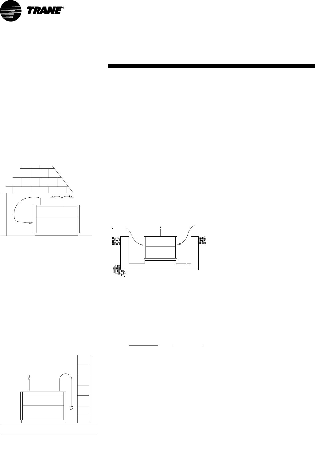
Figure AC-1 — Recommended Piping Components For Typical Evaporator Installation
20–60 Ton
10, 15 Ton
Note: Provide shutoff valves in the evaporator inlet
and outlet to facilitate water temperature sensor
removal.
Water Inlet and Outlet locations depend on unit size.
3. Strainer has threaded inlet/outlet.
4. Tee for Flow Switch to be field provided.
See Detail "A"
2. Evaporator is shown for illustration purposes only.
Notes:
1. Shutoff valves are required for evaporator servicing.
Gauge
Unions
Eliminators
Vibration
Thermometers
Strainer
Return Line
(See Note 1)
(Inlet)
Gate Valves
(See Note 2)
Shutoff
Valves
Supply
(Outlet)
Line
Flow Switch
Balancing Valve
Pressure
Vent
Vent
Water
(Factory
Provided)
(Factory Provided)
Grooved to threaded nipple
w/coupling
(Factory Supplied)
Detail A
NIPPLE
NIPPLE
(Factory Provided)
See unit dimensional
drawings for inlet
and outlet locations.
CG-PRC007-EN14
Selection
Procedure
The chiller capacity tables presented in
the “Performance Data” section cover
the most frequently encountered leaving
water temperatures. The tables reflect a
10°F temperature drop through the
evaporator. For temperature drops other
than 10°F, fouling factors other than
0.0001 (in accordance with ARI Standard
550/590-98) and for units operating at
altitudes that are significantly greater
than sea level, refer to the “Performance
Adjustment Factors” section and apply
the appropriate adjustment factors. For
chilled brine selections, refer to the
“Performance Adjustment Factors”
section for ethylene glycol adjustment
factors.
To select a Trane air-cooled chiller, the
following information is required:
1
Design system load (in tons of
refrigeration).
2
Design leaving chilled water
temperature.
3
Design chilled water temperature drop.
4
Design ambient temperature.
5
Evaporator fouling factor.
Evaporator chilled water flow rate can be
determined by using the following
formula: Tons x 24
GPM = Temperature Drop (Degrees F)
NOTE: Flow rate must fall within the
limits specified in the “General Data”
section of this catalog.
SELECTION EXAMPLE
Given:
Required System Load = 53 tons
Leaving Chilled Water Temperature
(LCWT) = 45°F
Chilled Water Temperature Drop = 10°F
Design Ambient Temperature = 95°F
Evaporator Fouling Factor = 0.0001
System Power Input = 70.2 KW
Unit EER = 9.8
MINIMUM LEAVING CHILLED WATER
TEMPERATURE SET POINTS
The minimum leaving chilled water
temperature set point for water is listed
in the following table:
Table SP-1 — Minimum Leaving Chilled
Water Temperature Set points for Water1
Evaporator Minimum Leaving Chilled Water
Temperature Temperature Set point (°F)
Difference CGAF- CGAF-
(Degrees F) C20,C25,C30 C40,C50,C60
64039
84139
10 42 40
12 43 40
14 44 41
16 45 41
18 46 42
1These are for units without HGBP, for units with
HGBP, add 2°F to each minimum temperature in the
table.
For those applications requiring lower
set points, a glycol solution must be
used. The minimum leaving chilled
water set point for a glycol solution can
be calculated using the following
equation:
LCWS (Minimum) = GFT + 5 + ∆ T
(Evap)
# of stages of capacity.
LCWS = Leaving Chilled Water
Set point (F)
GFT = Glycol Freezing
Temperature (F)
∆ T = Delta T (the difference
between the temperature
of the water entering and
leaving the evaporator)
Solution freezing point temperatures can
be found in the Performance Data
section and the number of stages of
capacity in the General Data section. For
selection assistance, refer to the CGA
Chiller Selection program.
1
To calculate the required chilled
waterflow rate we use the formula:
GPM = Tons x 24
∆T
From the 60 ton unit table in the
“Performance Data” section of this
catalog, a CGAF-C60 at the given
conditions will produce 57.3 tons with a
system power input of 70.2 kw and a unit
EER of 9.8
GPM = 56.8 Tons x 24 = 137.5
10°F
2
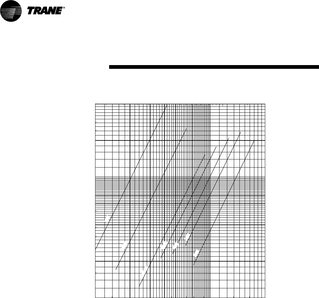
To determine the evaporator water
pressure drop we use the flow rate
(gpm) and the evaporator water
pressure drop curves found in the
“Performance Adjustment Factors”
section of this catalog. Entering the curve
at 137.5 gpm, the pressure drop for a
nominal 60 ton evaporator is 16.5 feet.
3
For selection of chilled brine units or
applications where the altitude is
significantly greater than sea level or the
temperature drop is different than 10°F,
the performance adjustment factors
should be applied at this point.
For example:
Corrected Capacity = Capacity
(unadjusted) x Appropriate Adjustment
Factor
Corrected Flow Rate = Flow Rate
(unadjusted) x Appropriate Adjustment
Factor
Corrected KW Input = KW Input
(unadjusted) x Appropriate Adjustment
Factor
4
Verify that the selection is within design
guidelines. The final unit selection is:
Quantity (1) CGAF-C60
Cooling Capacity = 57.3 Tons
Entering/Leaving Chilled Water
Temperatures = 55/45°F
Chilled Waterflow Rate (GPM) = 137.5
Evaporator Water Pressure Drop = 16.5
ft.
15CG-PRC007-EN
Model
Number
Description
CGA 120 B 3 00 B A
123 456 7 8 9,10 11 12
DIGIT 10 — Leaving Solution Set point
0 =Standard Expansion Valve
40-60°F Leaving Water
(CGA100 & CGA120 models)
20-60°F Leaving Solution
(CGA150 & CGA180 Models)
V = Nonstandard Expansion Valve
20-39°F Leaving Solution
(CGA100 & CGA120 models)
DIGIT 11 — Minor Design Change
A = First, B = Second, etc.
DIGIT 12 —Service Digit
DIGIT 1,2,3 — Unit Type
CGA = Air-Cooled Cold Generator™
DIGITS 4,5,6 — Nominal Capacity (MBh)
100 = 8 Tons (50 Hz Model only)
120 = 10 Tons (60 Hz Model only)
150 = 12.5 Tons (50 Hz Model Only)
180 = 15 Tons (60 Hz Model Only)
DIGIT 7 — Major Design Change
(Number of Refrigerant Circuits/Number of
Compressors)
B = 2 Refrigerant Circuits/2 Compressors
DIGIT 8 — Voltage
1 = 208-230/60/1
(Available — CGA120 Only)
3 = 208-230/60/3
4 = 460/60/3
W = 575/60/3
D = 380-415/50/3
DIGIT 9 — Factory Installed Options
0 = No Options
H = Hot Gas Bypass
C = Black Epoxy Coil Standard Deviation
K = Hot Gas Bypass & Black Epoxy Coil
S = Special
10, 15 Tons
20–60 Tons
DIGIT 1,2 — Unit Model
CG = IntelliPak™ Air-Cooled Chiller
DIGIT 3 — Unit Type
A = Air-Cooled Condensing
DIGIT 4 — Development Sequence
A, B, C, etc.
DIGIT 5,6,7 — Nominal Capacity
C20 = 20 Tons
C25 = 25 Tons
C30 = 30 Tons
C40 = 40 Tons
C50 = 50 Tons
C60 = 60 Tons
DIGIT 8 — Voltage & Start Characteristics
E = 200/60/3 XL
F = 230/60/3 XL
4 = 460/60/3 XL
5 = 575/60/3 XL
9 = 380/50/3 XL
D = 415/50/3 XL
S = Special
DIGIT 9 — Factory Input
A = Standard
CG A F C40 4 A A A 1 A A A A A 0 0 0 0 0 0 0 01
12 3 4 567 8 9 10 11 12 13 14 15 16 17 18 19 20 21 22 23 24 25
DIGIT 10 — Design Sequence
A = First
B = Second
Etc...
DIGIT 11 — Leaving Solution Set point
A = 40-50 Deg. F w/o Ice Machine
B = 30-39 Deg. F w/o Ice Machine
D = 51-65 Deg. F w/o Ice Machine
E = 20-29 Deg. F w/o Ice Machine
1 = 40-50 Deg. F with Ice Machine
2 = 30-39 Deg. F with Ice Machine
3 = 51-65 Deg. F with Ice Machine
4 = 20-29 Deg. F with Ice Machine
S = Special
DIGIT 12 — Agency Approval
1 = UL/CSA
0 = None
DIGITS 13-25 — Miscellaneous
A = Trane Communication Interface
(TCI) Module
B = No Unit Heat Tape (50 Hz Only)
C = Compressor Current Sensing (CSM)
D = Unit Mounted Disconnect Switch
Nonfused
E = Unit Isolators Neoprene
F = Unit Isolators Spring
G = Superheat/Sub-Cooling
H = Hot Gas Bypass
The following items can be ordered for
separate shipment —
•Unit Isolators —Neoprene*
•Unit Isolators —Spring*
•Electronic Low Ambient Damper(s)
•Trane Communication Interface Module
(TCI)
•Generic B A S Module (GBAS)
•(0-5 volt Analog Input/Binary Output)
•Generic B A S Module (GBAS)
•(0-10 volt Analog Input/Output)
•Remote Human Interface
•Remote Set point Potentiometer
•Zone Sensor (Chilled Solution Reset)
•Inter-Processor Communication Bridge
(IPCB)
*Unit size must be specified when ordering
this item.
J = Generic B A S Module
(0-5 v Input, Binary Output)
M = Remote Human Interface
N = Generic B A S Module
(0-10 v Analog)
P = Remote Set point Potentiometer
Q = Zone Sensor — Chilled Solution
Reset
V = Copper Fin Condenser Coils
W= Electronic Low Ambient Damper(s)
Y = Inter-Processor Communication
Bridge (IPCB)
9 = Packed Stock Unit
1. The service digit for each model number contains 25
digits; all 25 digits must be referenced.
CG-PRC007-EN16
General Data
Table GD-1 — General Data — 10–60 Ton Units
10 Ton 15 Ton 20 Ton 25 Ton 30 Ton 40 Ton 50 Ton 60 Ton
Model Number CGA120 CGA180 CGAF-C20 CGAF-C25 CGAF-C30 CGAF-C40 CGAF-C50 CGAF-C60
Compressor Data
Model Scroll Scroll Scroll Scroll Scroll Scroll Scroll Scroll
Quantity 2 2 2 1/1 2 4 2/2 4
Nominal Tons per Compressor 5 7.5 10 10/15 15 10 10/15 15
Evaporator
Nominal Size (Tons) 10152025 30405060
Water Storage Capacity (Gallons)²1.4 1.5 2.2 2.7 3.2 4.1 5.0 7.4
Min. Flow Rate (GPM) 12.018.02430 36486072
Max. Flow Rate (GPM) 36.0 54.0 72 90 108 144 180 216
Max EWT At Start-Up — Deg F³10 0 100 108 108 108 108 108 108
Condenser
Nominal Size (Tons) 10152025 30405060
Number of Coils 1 2 1 2 2 2 2 2
Coil Size (ea., Inches)428 x 108 28 x 83 61 x 71 45 x 71/35 x 71 56 x 70 56 x 70 57 x 96 57 x 96
Number of Rows 2233 3334
Subcooler Size (ea., Inches) 4 x 10⁸ 4 x 83 10 x 71 14 x 71 9 x 70 9 x 70 9 x 96 9 x 96
Condenser Fans
Quantity 1 2 2 3 4 4 6 6
Diameter (Inches) 28 26 26 26 26 26 26 26
CFM (Total) 8,120 11,600 15,000 21,650 29,200 29,200 42,300 40,700
Nominal RPM 1100 1100 1140 1140 1140 1140 1140 1140
Tip Speed (Ft/Min) 8060 7490 7750 7750 7750 7750 7750 7750
Motor HP (ea.) 1.0 1/2 1.0 1.0 1.0 1.0 1.0 1.0
Drive Type Direct Direct Direct Direct Direct Direct Direct Direct
Minimum Outdoor Air Temperature Permissible
For Mechanical Cooling¹
Standard Ambient Control Unit (°F) 50 50 30 30 30 30 30 30
Standard Ambient w/Hot Gas Bypass (°F) 60 60 40 40 40 40 40 40
Low Ambient Option (°F) 0000 0000
Low Ambient Control w/Hot Gas Bypass(°F) 15 15 10 10 10 10 10 10
General Unit
Unload Steps 100-50 100-50 100-50 100-60-40 100-50 100-75-50-25 100-80-60-30 100-75-50-25
No. of Independent Refrig. Circuits 2 2 1 1 1 2 2 2
Refrigerant Charge (lbs. R22/Circuit) 8.25 11.5 40.5 54.0 72.0 38.0 47.0 67.0
Oil Charge (Pints/Circuit) 4.1 7.5 17.0 22.3 27.6 17.0 22.3 27.6
*Unloading steps depend upon which compressor is lead compressor.
Notes:
1. Minimum start-up ambient based on unit at minimum step of unloading and a 5 mph wind across the condenser.
2. Includes piping internal to chiller.
3. At 95°F ambient.
4. Does not include subcooling portion of coil.

17CG-PRC007-EN
Chilled Altitude
Fouling Water Sea Level 2,000 Feet 4,000 Feet 6,000 Feet
Factor ∆T CAP GPM KW CAP GPM KW CAP GPM KW CAP GPM KW
6 1.00 1.66 1.00 0.98 1.63 1.01 0.95 1.59 1.02 0.93 1.54 1.05
8 1.00 1.25 1.00 0.98 1.22 1.01 0.96 1.19 1.02 0.93 1.16 1.05
0.00025 10 1.00 1.00 1.00 0.98 0.98 1.01 0.95 0.95 1.02 0.92 0.92 1.04
12 1.00 0.83 1.00 0.98 0.81 1.01 0.95 0.79 1.02 0.92 0.77 1.04
14 0.99 0.71 1.00 0.97 0.59 1.01 0.95 0.68 1.02 0.92 0.66 1.04
6 0.96 1.60 0.98 0.94 1.57 0.99 0.92 1.53 1.00 0.90 1.49 1.01
8 0.96 1.20 0.98 0.94 1.18 0.99 0.92 1.15 1.00 0.90 1.12 1.01
0.001 10 0.96 0.96 0.98 0.94 0.94 0.99 0.92 0.92 1.00 0.89 0.89 1.01
12 0.96 0.80 0.98 0.94 0.79 0.99 0.92 0.77 1.00 0.89 0.74 1.01
14 0.96 0.68 0.98 0.94 0.67 0.99 0.92 0.65 1.00 0.89 0.66 1.01
8 0.93 1.15 0.95 0.91 1.13 0.96 0.88 1.10 0.98 0.86 1.07 0.99
0.002 10 0.90 0.90 0.94 0.89 0.88 0.95 0.87 0.87 0.96 0.85 0.84 0.98
12 0.90 0.75 0.94 0.88 0.73 0.95 0.86 0.72 0.95 0.84 0.70 0.98
14 0.90 0.64 0.94 0.87 0.63 0.95 0.86 0.82 0.95 0.84 0.60 0.98
*Standard chilled water ∆ is 8-12 for CGA120-180.
Standard chilled water ∆ is 6-16 for CGAF 20-60.
Table PAF-1— Performance Adjustment Factors (10 & 15 Ton Units Only)
Performance
Adjustment
Factors
Chilled Altitude
Fouling Water Sea Level 2,000 Feet 4,000 Feet 6,000 Feet
Factor ∆T CAP GPM KW CAP GPM KW CAP GPM KW CAP GPM KW
6 0.987 1.650 0.993 0.967 1.640 1.003 0.952 1.620 1.019 0.932 1.570 1.029
8 0.993 1.250 0.997 0.973 1.240 1.007 0.956 1.220 1.025 0.935 1.190 1.035
0.00025 10 1.000 1.000 1.000 0.980 0.990 1.010 0.960 0.970 1.030 0.940 0.940 1.040
12 1.007 0.820 1.003 0.987 0.810 1.013 0.966 0.800 1.035 0.945 0.780 1.045
14 1.013 0.710 1.007 0.993 0.700 1.017 0.972 0.680 1.038 0.952 0.660 1.048
16 1.020 0.640 1.010 1.000 0.630 1.020 0.980 0.620 1.040 0.960 0.600 1.050
6 0.957 1.615 0.979 0.953 1.600 0.989 0.931 1.570 0.990 0.914 1.540 1.002
8 0.964 1.215 0.982 0.959 1.210 0.992 0.937 1.180 0.994 0.920 1.170 1.006
0.001 10 0.970 0.965 0.985 0.964 0.960 0.995 0.943 0.940 0.998 0.926 0.920 1.009
12 0.976 0.785 0.989 0.966 0.790 0.998 0.945 0.770 1.007 0.926 0.760 1.018
14 0.982 0.675 0.993 0.968 0.670 1.001 0.947 0.650 1.016 0.927 0.640 1.027
16 0.989 0.620 0.996 0.970 0.600 1.004 0.949 0.590 1.025 0.927 0.580 1.036
6 0.916 1.565 0.951 0.913 1.550 0.969 0.896 1.490 0.975 0.871 1.450 0.984
8 0.923 1.245 0.958 0.919 1.170 0.972 0.898 1.110 0.979 0.874 1.080 0.987
0.002 10 0.930 0.925 0.965 0.925 0.920 0.975 0.900 0.890 0.982 0.877 0.880 0.989
12 0.934 0.810 0.969 0.927 0.750 0.978 0.908 0.730 0.986 0.885 0.720 0.993
14 0.938 0.695 0.973 0.929 0.640 0.981 0.916 0.620 0.989 0.894 0.610 0.997
16 0.948 0.580 0.976 0.931 0.580 0.983 0.924 0.580 0.993 0.902 0.570 1.001
Table PAF-2— Performance Adjustment Factors (20-60 Ton Units Only)
CG-PRC007-EN18
Chart PAF-1 — Evaporator Water Pressure Drop 10 to 60 Ton Air-Cooled Chillers
Performance
Adjustment
Factors
1.5
2
2.5
3
3.5
4
4.5
5
5.5
6
6.5
7
7.5
8
8.5
9
9.5
10
10
10
15
10 Ton
15 Ton
60 Ton
50 Ton
40 Ton
30 Ton
20 & 25 Ton
Pressure Drop (Ft of Water)
Flow (GPM)
101010 20 30 40 50 60 70 80 90 100100 200 300
11
2
3
4
5
6
7
8
9
10
20
30
40
Flow (L/S)
19CG-PRC007-EN
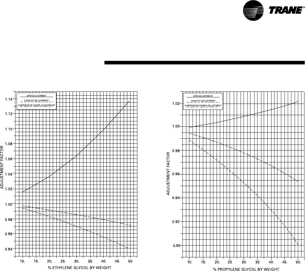
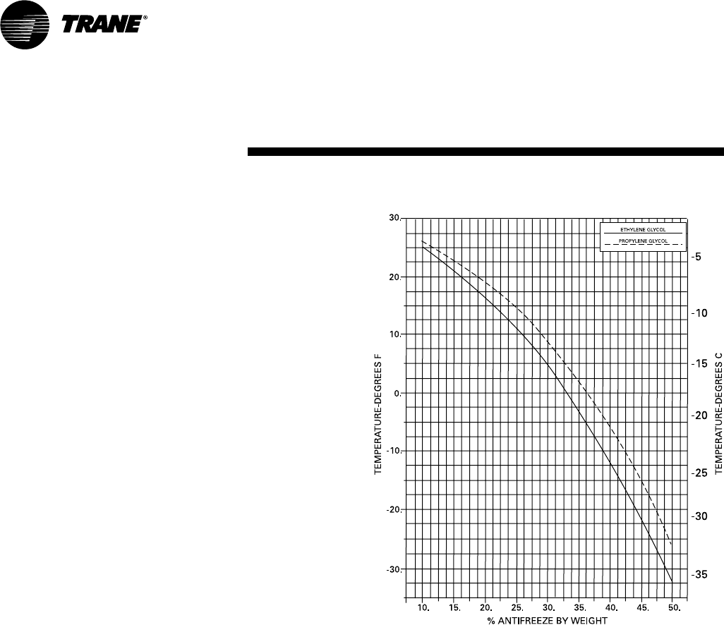
Chart PAF-2— Ethylene Glycol Performance Factors Chart PAF-3— Propylene Glycol Performance Factors
Performance
Adjustment
Factors
CG-PRC007-EN20
Chart PAF-4— Ethylene Glycol and Propylene Glycol Performance Factors
Performance
Adjustment
Factors
21CG-PRC007-EN
Performance
Data — 60 HZ
(10–15 Ton)
Full Load
Entering Condenser Air Temperature (Degree F)
75.0 85.0 95.0 105.0 115.0
LWT Percent Capacity System Capacity System Capacity System Capacity System Capacity System
(Deg F) Glycol (Tons) KW EER (Tons) KW EER (Tons) KW EER (Tons) KW EER (Tons) KW EER
20 28 6.0 7.6 9.4 5.6 8.5 8.0 5.4 9.4 6.9 5.1 10.4 5.9 4.9 11.5 5.1
25 24 6.6 7.8 10.2 6.3 8.6 8.7 6.0 9.6 7.5 5.7 10.6 6.4 5.4 11.8 5.5
30 19 7.3 8.0 11.0 6.9 8.8 9.4 6.6 9.8 8.1 6.3 10.8 7.0 6.0 12.0 6.0
35 14 8.0 8.2 11.8 7.7 9.0 10.2 7.3 10.0 8.8 6.9 11.1 7.5 6.6 12.3 6.4
40 0 8.9 8.4 12.6 8.5 9.3 11.0 8.1 10.3 9.5 7.7 11.4 8.1 7.3 12.6 6.9
42 0 9.2 8.5 13.0 8.8 9.4 11.3 8.4 10.4 9.7 8.0 11.5 8.3 7.5 12.7 7.1
44 0 9.5 8.6 13.3 9.1 9.5 11.6 8.7 10.5 10.0 8.3 11.6 8.6 7.8 12.8 7.3
45 0 9.7 8.6 13.4 9.3 9.5 11.7 8.9 10.5 10.1 8.4 11.6 8.7 7.9 12.9 7.4
46 0 9.8 8.7 13.6 9.4 9.6 11.8 9.0 10.6 10.3 8.6 11.7 8.8 8.1 12.9 7.5
48 0 10.2 8.8 13.9 9.8 9.7 12.1 9.3 10.7 10.5 8.9 11.8 9.0 8.4 13.0 7.7
50 0 10.5 8.9 14.2 10.1 9.8 12.4 9.7 10.8 10.8 9.2 11.9 9.3 8.7 13.2 7.9
55 0 11.4 9.1 15.0 11.0 10.0 13.2 10.5 11.0 11.4 10.0 12.2 9.8 9.4 13.5 8.4
60 0 12.4 9.4 15.8 11.9 10.3 13.9 11.4 11.3 12.1 10.8 12.5 10.4 10.2 13.8 8.9
Table PD-2 — 15 Ton — CGA 180
Entering Condenser Air Temperature (Degree F)
75.0 85.0 95.0 105.0 115.0
LWT Percent Capacity System Capacity System Capacity System Capacity System Capacity System
(Deg F) Glycol (Tons) KW EER (Tons) KW EER (Tons) KW EER (Tons) KW EER (Tons) KW EER
20 28 9.3 12.2 9.1 8.9 13.6 7.8 8.4 15.3 6.6 7.9 17.2 5.5 7.3 19.3 4.5
25 24 10.3 12.5 9.9 9.8 13.9 8.5 9.3 15.6 7.2 8.7 17.5 6.0 8.1 19.7 5.0
30 19 11.4 12.7 10.7 10.9 14.2 9.2 10.3 15.9 7.8 9.7 17.8 6.5 9.0 20.0 5.4
35 14 12.6 13.0 11.6 12.0 14.5 9.9 11.4 16.2 8.4 10.7 18.2 7.1 10.0 20.4 5.9
40 0 13.9 13.3 12.5 13.3 14.9 10.7 12.6 16.6 9.1 11.9 18.6 7.7 11.1 20.9 6.4
42 0 14.4 13.5 12.9 13.8 15.0 11.0 13.1 16.8 9.4 12.3 18.8 7.9 11.6 21.1 6.6
44 0 15.0 13.6 13.2 14.3 15.1 11.3 13.6 16.9 9.6 12.8 19.0 8.1 12.0 21.3 6.8
45 0 15.2 13.7 13.4 14.5 15.2 11.5 13.8 17.0 9.7 13.0 19.0 8.2 12.2 21.3 6.9
46 0 15.5 13.7 13.5 14.8 15.3 11.6 14.1 17.1 9.9 13.3 19.1 8.3 12.5 21.4 7.0
48 0 16.0 13.9 13.9 15.3 15.4 11.9 14.6 17.2 10.1 13.8 19.3 8.6 12.9 21.6 7.2
50 0 16.6 14.0 14.2 15.9 15.6 12.2 15.1 17.4 10.4 14.3 19.5 8.8 13.4 21.8 7.4
55 0 18.0 14.4 15.1 17.2 16.0 12.9 16.4 17.8 11.0 15.5 19.9 9.3 14.6 22.3 7.9
60 0 19.5 14.8 15.9 18.7 16.4 13.7 17.8 18.3 11.7 16.9 20.4 9.9 15.9 22.8 8.4
Notes:
1 Based on the ethylene glycol concentration shown, a 10° delta T, a fouling factor of 0.0001 and sea level pressure.
2 Performance must be corrected for glycol concentrations other than those showing, delta T other than 10°, fouling factor and altitude.
3 Ethylene glycol is to be added and appropriate performance corrections are to be made for all leaving solution temperatures less than 40°F.
4. Use the following equation to calculate COP values at other than ARI conditions, COP = EER x .2928.
5. Single Phase CGA120B1 model should be re-rated at all operating points using the following factors: 1.08 x KW , 0.92 x EER
Table PD-1 — 10 Ton — CGA 120
5
CG-PRC007-EN22
Performance
Data — 60 HZ
Table PD-3 — 20 Ton — CGAF-C20
Entering Condenser Air Temperature (Degree F)
75.0 85.0 95.0 105.0 115.0
LWT Percent Capacity System Capacity System Capacity System Capacity System Capacity System
(Deg F) Glycol (Tons) KW EER (Tons) KW EER (Tons) KW EER (Tons) KW EER (Tons) KW EER
20 28 12.0 15.6 9.2 11.4 17.3 8.0 10.8 19.2 6.8 10.1 21.3 5.7 9.4 23.8 4.8
25 24 13.4 16.0 10.0 12.7 17.7 8.6 12.1 19.6 7.4 11.3 21.8 6.2 10.6 24.3 5.2
30 19 14.8 16.4 10.8 14.1 18.1 9.4 13.4 20.1 8.0 12.6 22.3 6.8 11.8 24.9 5.7
35 14 16.4 16.9 11.6 15.6 18.6 10.1 14.8 20.6 8.6 14.0 22.9 7.3 13.1 25.4 6.2
40 0 18.1 17.4 12.5 17.3 19.2 10.9 16.4 21.2 9.3 15.5 23.5 7.9 14.5 26.1 6.7
42 0 18.8 17.6 12.8 18.0 19.4 11.1 17.0 21.4 9.6 16.1 23.7 8.1 15.1 26.3 6.9
44 0 19.5 17.8 13.2 18.6 19.6 11.4 17.7 21.6 9.8 16.7 24.0 8.3 15.6 26.5 7.1
45 0 19.8 17.9 13.3 18.9 19.7 11.5 18.0 21.7 9.9 17.0 24.1 8.5 15.9 26.7 7.1
46 0 20.1 18.0 13.5 19.2 19.8 11.7 18.3 21.8 10.0 17.3 24.2 8.6 16.2 26.8 7.2
48 0 20.8 18.2 13.8 19.9 20.0 11.9 18.9 22.1 10.3 17.9 24.4 8.8 16.7 27.0 7.4
50 0 21.5 18.4 14.1 20.6 20.2 12.2 19.5 22.3 10.5 18.5 24.7 9.0 17.3 27.3 7.6
55 0 23.3 18.9 14.8 22.3 20.8 12.9 21.2 22.9 11.1 20.0 25.3 9.5 18.8 27.9 8.1
60 0 25.2 19.4 15.5 24.0 21.4 13.5 22.9 23.5 11.7 21.6 26.0 10.0 20.3 28.6 8.5
Table PD-4 — 25 Ton — CGAF-C25
Entering Condenser Air Temperature (Degree F)
75.0 85.0 95.0 105.0 115.0
LWT Percent Capacity System Capacity System Capacity System Capacity System Capacity System
(Deg F) Glycol (Tons) KW EER (Tons) KW EER (Tons) KW EER (Tons) KW EER (Tons) KW EER
20 28 15.6 20.9 8.9 14.8 22.9 7.8 14.0 25.2 6.7 13.2 27.8 5.7 12.3 30.7 4.8
25 24 17.4 21.4 9.7 16.5 23.4 8.5 15.7 25.8 7.3 14.7 28.4 6.2 13.8 31.4 5.3
30 19 19.3 21.9 10.6 18.4 24.0 9.2 17.4 26.4 7.9 16.4 29.1 6.8 15.4 32.1 5.8
35 14 21.3 22.5 11.4 20.4 24.6 9.9 19.3 27.0 8.6 18.2 29.8 7.4 17.1 32.8 6.3
40 0 23.7 23.1 12.3 22.6 25.3 10.7 21.5 27.8 9.3 20.3 30.6 8.0 19.1 33.7 6.8
42 0 24.6 23.3 12.6 23.5 25.5 11.0 22.3 28.0 9.5 21.1 30.8 8.2 19.8 34.0 7.0
44 0 25.4 23.6 13.0 24.3 25.8 11.3 23.1 28.3 9.8 21.9 31.1 8.4 20.6 34.3 7.2
45 0 25.9 23.7 13.1 24.7 25.9 11.5 23.5 28.4 9.9 22.3 31.3 8.5 21.0 34.4 7.3
46 0 26.3 23.8 13.3 25.2 26.0 11.6 23.9 28.6 10.0 22.7 31.4 8.7 21.3 34.6 7.4
48 0 27.3 24.1 13.6 26.0 26.3 11.9 24.8 28.9 10.3 23.5 31.7 8.9 22.1 34.9 7.6
50 0 28.2 24.3 13.9 26.9 26.6 12.2 25.6 29.2 10.6 24.3 32.0 9.1 22.9 35.2 7.8
55 0 30.6 25.0 14.7 29.2 27.3 12.9 27.8 29.9 11.2 26.4 32.8 9.6 24.9 36.1 8.3
60 0 33.0 25.6 15.5 31.6 28.0 13.5 30.1 30.7 11.8 28.6 33.7 10.2 27.0 36.9 8.8
Notes:
1. Data based on 0.0001 fouling factor at sea level.
2. Interpolation between points is permissible.
3. Extrapolation beyond points is not permissible.
4. EER - Energy Efficiency Ratio (Btu/watt-hour). Power inputs include compressors,
condenser fans and control power.
5. Ratings based on evaporator drop of 10°F.
6. Rated in accordance with ARI Standard 550/590-98.
7. Minimum recommended ethylene glycol percentage used for leaving water temperatures below 40°F.
8. Use the following equation to calculate COP values at other than ARI conditions, COP = EER x .2928.
(20–25 Ton)
Full Load
23CG-PRC007-EN
Performance
Data — 60 HZ
(30–40 Ton)
Full Load
Entering Condenser Air Temperature (Degree F)
75.0 85.0 95.0 105.0 115.0
LWT Percent Capacity System Capacity System Capacity System Capacity System Capacity System
(Deg F) Glycol (Tons) KW EER (Tons) KW EER (Tons) KW EER (Tons) KW EER (Tons) KW EER
20 28 18.8 25.7 8.8 17.9 28.1 7.6 16.9 30.9 6.6 15.9 34.0 5.6 14.9 37.6 4.7
25 24 21.0 26.3 9.6 20.0 28.7 8.4 18.9 31.5 7.2 17.8 34.8 6.2 16.7 38.4 5.2
30 19 23.3 26.8 10.4 22.2 29.3 9.1 21.1 32.2 7.9 19.9 35.5 6.7 18.7 39.2 5.7
35 14 25.8 27.4 11.3 24.6 29.9 9.9 23.4 32.9 8.5 22.1 36.2 7.3 20.8 40.0 6.2
40 0 28.7 28.0 12.3 27.4 30.7 10.7 26.1 33.7 9.3 24.7 37.1 8.0 23.2 40.9 6.8
42 0 29.7 28.3 12.6 28.4 30.9 11.0 27.0 34.0 9.5 25.6 37.4 8.2 24.1 41.3 7.0
44 0 30.8 28.5 13.0 29.5 31.2 11.3 28.0 34.3 9.8 26.6 37.7 8.4 25.0 41.6 7.2
45 0 31.4 28.6 13.1 30.0 31.3 11.5 28.5 34.4 9.9 27.0 37.9 8.6 25.5 41.8 7.3
46 0 31.9 28.8 13.3 30.5 31.5 11.6 29.0 34.6 10.1 27.5 38.1 8.7 26.0 41.9 7.4
48 0 33.0 29.0 13.6 31.6 31.8 11.9 30.1 34.9 10.3 28.5 38.4 8.9 26.9 42.3 7.6
50 0 34.1 29.3 14.0 32.7 32.0 12.2 31.1 35.2 10.6 29.5 38.7 9.1 27.9 42.6 7.8
55 0 37.0 29.9 14.8 35.5 32.8 13.0 33.8 36.0 11.3 32.1 39.6 9.7 30.3 43.5 8.4
60 0 40.1 30.6 15.7 38.4 33.5 13.7 36.6 36.8 11.9 34.8 40.4 10.3 32.9 44.5 8.9
Table PD-5— 30 Ton — CGAF-C30
Table PD-6 — 40 Ton — CGAF-C40
Entering Condenser Air Temperature (Degree F)
75.0 85.0 95.0 105.0 115.0
LWT Percent Capacity System Capacity System Capacity System Capacity System Capacity System
(Deg F) Glycol (Tons) KW EER (Tons) KW EER (Tons) KW EER (Tons) KW EER (Tons) KW EER
20 28 23.0 30.9 8.9 21.9 34.1 7.7 20.7 37.9 6.6 19.5 42.3 5.5 18.1 47.2 4.6
25 24 25.7 31.7 9.7 24.5 35.0 8.4 23.2 38.8 7.2 21.8 43.2 6.1 20.3 48.2 5.1
30 19 28.6 32.5 10.6 27.3 35.8 9.2 25.9 39.7 7.8 24.4 44.2 6.6 22.8 49.2 5.5
35 14 31.8 33.3 11.4 30.3 36.7 9.9 28.8 40.7 8.5 27.1 45.2 7.2 25.3 50.3 6.0
40 0 35.4 34.3 12.4 33.8 37.8 10.7 32.1 41.9 9.2 30.2 46.4 7.8 28.3 51.6 6.6
42 0 36.7 34.7 12.7 35.0 38.2 11.0 33.3 42.3 9.4 31.4 46.9 8.0 29.4 52.0 6.8
44 0 38.0 35.0 13.0 36.3 38.6 11.3 34.5 42.7 9.7 32.5 47.3 8.2 30.5 52.5 7.0
45 0 38.7 35.2 13.2 36.9 38.8 11.4 35.1 42.9 9.8 33.1 47.5 8.4 31.0 52.7 7.1
46 0 39.3 35.4 13.3 37.6 39.0 11.6 35.7 43.1 9.9 33.7 47.8 8.5 31.6 53.0 7.2
48 0 40.7 35.8 13.7 38.9 39.4 11.8 36.9 43.5 10.2 34.9 48.2 8.7 32.7 53.4 7.3
50 0 42.1 36.2 14.0 40.2 39.8 12.1 38.2 44.0 10.4 36.1 48.7 8.9 33.9 53.9 7.5
55 0 45.6 37.2 14.7 43.6 40.9 12.8 41.5 45.1 11.0 39.2 49.9 9.4 36.8 55.2 8.0
60 0 49.3 38.2 15.5 47.1 42.0 13.5 44.8 46.3 11.6 42.4 51.1 10.0 39.8 56.5 8.5
Notes:
1. Data based on 0.0001 fouling factor at sea level.
2. Interpolation between points is permissible.
3. Extrapolation beyond points is not permissible.
4. EER - Energy Efficiency Ratio (Btu/watt-hour). Power inputs include compressors, water temperatures below 40°F.
5. Ratings based on evaporator drop of 10°F condenser fans and control power
6. Rated in accordance with ARI Standard 550/590-98.
7. Minimum recommended ethylene glycol percentage used for leaving water temperatures below 40°F.
8. Use the following equation to calculate COP values at other than ARI conditions, COP = EER x .2928.
CG-PRC007-EN24
Performance
Data — 60 HZ
Entering Condenser Air Temperature (Degree F)
75.0 85.0 95.0 105.0 115.0
LWT Percent Capacity System Capacity System Capacity System Capacity System Capacity System
(Deg F) Glycol (Tons) KW EER (Tons) KW EER (Tons) KW EER (Tons) KW EER (Tons) KW EER
20 28 37.2 50.1 8.9 35.3 55.0 7.7 33.4 60.7 6.6 31.3 67.2 5.6 29.2 74.6 4.7
25 24 41.6 51.3 9.7 39.6 56.4 8.4 37.4 62.2 7.2 35.2 68.8 6.1 32.9 76.3 5.2
30 19 46.4 52.6 10.6 44.1 57.8 9.2 41.8 63.8 7.9 39.4 70.6 6.7 36.8 78.2 5.7
35 14 51.4 54.0 11.4 48.9 59.3 9.9 46.4 65.4 8.5 43.7 72.3 7.3 41.0 80.1 6.1
40 0 57.2 55.6 12.3 54.5 61.1 10.7 51.7 67.3 9.2 48.8 74.4 7.9 45.8 82.2 6.7
42 0 59.2 56.2 12.7 56.5 61.7 11.0 53.6 68.0 9.5 50.6 75.1 8.1 47.5 83.0 6.9
44 0 61.4 56.8 13.0 58.5 62.3 11.3 55.6 68.7 9.7 52.5 75.9 8.3 49.3 83.8 7.1
45 0 62.5 57.1 13.1 59.6 62.7 11.4 56.6 69.1 9.8 53.4 76.2 8.4 50.2 84.2 7.2
46 0 63.6 57.4 13.3 60.6 63.0 11.5 57.6 69.4 9.9 54.4 76.6 8.5 51.1 84.6 7.2
48 0 65.8 58.0 13.6 62.7 63.7 11.8 59.6 70.2 10.2 56.3 77.4 8.7 52.9 85.4 7.4
50 0 68.0 58.6 13.9 64.9 64.4 12.1 61.7 70.9 10.4 58.3 78.2 8.9 54.8 86.3 7.6
55 0 73.8 60.3 14.7 70.4 66.1 12.8 66.9 72.8 11.0 63.3 80.2 9.5 59.6 88.4 8.1
60 0 79.7 62.0 15.4 76.1 68.0 13.4 72.4 74.8 11.6 68.5 82.4 10.0 64.5 90.7 8.5
Entering Condenser Air Temperature (Degree F)
75.0 85.0 95.0 105.0 115.0
LWT Percent Capacity System Capacity System Capacity System Capacity System Capacity System
(Deg F) Glycol (Tons) KW EER (Tons) KW EER (Tons) KW EER (Tons) KW EER (Tons) KW EER
20 28 28.5 39.7 8.6 27.1 43.4 7.5 25.6 47.7 6.4 24.1 52.6 5.5 22.5 58.2 4.6
25 24 31.9 40.5 9.4 30.4 44.3 8.2 28.7 48.7 7.1 27.1 53.8 6.0 25.3 59.5 5.1
30 19 35.6 41.4 10.3 33.9 45.3 9.0 32.1 49.8 7.7 30.3 55.0 6.6 28.4 60.7 5.6
35 14 39.5 42.4 11.2 37.7 46.4 9.7 35.8 51.0 8.4 33.8 56.2 7.2 31.7 62.0 6.1
40 0 44.1 43.5 12.2 42.1 47.6 10.6 40.0 52.3 9.2 37.8 57.6 7.9 35.5 63.5 6.7
42 0 45.7 43.9 12.5 43.6 48.0 10.9 41.5 52.7 9.4 39.2 58.1 8.1 36.9 64.1 6.9
44 0 47.4 44.3 12.8 45.3 48.4 11.2 43.0 53.2 9.7 40.7 58.6 8.3 38.3 64.6 7.1
45 0 48.2 44.5 13.0 46.1 48.7 11.4 43.8 53.5 9.8 41.5 58.9 8.5 39.0 64.9 7.2
46 0 49.1 44.7 13.2 46.9 48.9 11.5 44.6 53.7 10.0 42.2 59.1 8.6 39.8 65.2 7.3
48 0 50.8 45.1 13.5 48.6 49.3 11.8 46.2 54.2 10.2 43.8 59.6 8.8 41.2 65.7 7.5
50 0 52.6 45.5 13.9 50.2 49.8 12.1 47.8 54.7 10.5 45.3 60.2 9.0 42.7 66.3 7.7
55 0 57.1 46.6 14.7 54.6 51.0 12.9 52.0 56.0 11.2 49.3 61.5 9.6 46.5 67.7 8.2
60 0 61.8 47.7 15.5 59.1 52.2 13.6 56.4 57.3 11.8 53.5 63.0 10.2 50.5 69.2 8.8
Table PD-8— 60 Ton — CGAF-C60
Table PD-7— 50 Ton — CGAF-C50
Notes:
1. Data based on 0.0001 fouling factor at sea level.
2. Interpolation between points is permissible.
3. Extrapolation beyond points is not permissible.
4. EER - Energy Efficiency Ratio (Btu/watt-hour). Power inputs include compressors, water temperatures below 40°F.
5. Ratings based on evaporator drop of 10°F
condenser fans and control power
6. Rated in accordance with ARI Standard 550/590-98.
7. Minimum recommended ethylene glycol percentage used for leaving water temperatures below 40°F.
8. Use the following equation to calculate COP values at other than ARI conditions, COP = EER x .2928.
(50–60 Ton)
Full Load
Table PD-9 — Coefficient of Performance (COP) and
Integrated Part Load Values (IPLV) at ARI Conditions
Tons Model Number IPLV COP
10 CGA120B212.3 2.9
15 CGA180B 12.9 2.8
20 CGAF-C20 14.8 2.8
25 CGAF-C25 14.6 2.8
30 CGAF-C30 13.9 2.8
40 CGAF-C40 14.9 2.8
50 CGAF-C50 14.5 2.8
60 CGAF-C60 15.0 2.8
Notes:
1. Integrated Part Load Values are EERs in (Btu/watt-hour).
2. CGA120B1 - Single Phase IPLV = 11.4, COP = 2.7
25CG-PRC007-EN
Performance
Data — 50 HZ
(10–30 Ton)
Full Load
Entering Condenser Air Temperature (Degree F)
85.0 95.0 105.0 115.0 120.0
LWT Percent Capacity System Capacity System Capacity System Capacity System Capacity System
(Deg F) Glycol (Tons) KW EER (Tons) KW EER (Tons) KW EER (Tons) KW EER (Tons) KW EER
40 0 7.2 7.6 11.4 6.8 8.4 9.7 6.4 9.4 8.2 6.0 10.5 6.9 5.8 11.1 6.3
42 0 7.4 7.6 11.7 7.1 8.5 10.0 6.7 9.5 8.4 6.3 10.6 7.1 6.1 11.2 6.5
44 0 7.7 7.7 12.0 7.3 8.6 10.2 6.9 9.6 8.7 6.5 10.7 7.3 6.3 11.3 6.7
45 0 7.9 7.8 12.1 7.5 8.7 10.3 7.1 9.7 8.8 6.6 10.8 7.4 6.4 11.4 6.8
46 0 8.0 7.9 12.2 7.6 8.7 10.5 7.2 9.7 8.9 6.8 10.8 7.5 6.6 11.4 6.9
48 0 8.3 8.0 12.5 7.9 8.8 10.7 7.5 9.8 9.1 7.0 10.9 7.7 6.8 11.5 7.1
50 0 8.6 8.1 12.8 8.2 9.0 11.0 7.7 10.0 9.3 7.3 11.1 7.9 7.1 11.7 7.3
Table PD-10— 10 Ton — CGA 120
Table PD-11— 15 Ton — CGA 180
Entering Condenser Air Temperature (Degree F)
85.0 95.0 105.0 115.0 120.0
LWT Percent Capacity System Capacity System Capacity System Capacity System Capacity System
(Deg F) Glycol (Tons) KW EER (Tons) KW EER (Tons) KW EER (Tons) KW EER (Tons) KW EER
40 0 11.2 12.1 11.1 10.6 13.8 9.2 10.0 15.7 7.6 9.3 17.8 6.2 8.9 19.0 5.6
42 0 11.6 12.2 11.4 11.0 13.9 9.5 10.3 15.8 7.9 9.6 17.9 6.4 9.3 19.1 5.8
44 0 12.0 12.4 11.7 11.4 14.0 9.8 10.7 15.9 8.1 10.0 18.1 6.6 9.7 19.3 6.0
45 0 12.2 12.4 11.8 11.6 14.1 9.9 10.9 16.0 8.2 10.2 18.2 6.8 9.9 19.4 6.1
46 0 12.5 12.5 12.0 11.8 14.1 10.1 11.2 16.1 8.3 10.4 18.2 6.9 10.1 19.4 6.2
48 0 12.9 12.6 12.3 12.3 14.3 10.3 11.6 16.2 8.6 10.8 18.4 7.1 10.5 19.6 6.4
50 0 13.4 12.7 12.6 12.7 14.4 10.6 12.0 16.3 8.8 11.2 18.5 7.3 10.9 19.7 6.6
Entering Condenser Air Temperature (Degree F)
85.0 95.0 105.0 115.0 120.0
LWT Percent Capacity System Capacity System Capacity System Capacity System Capacity System
(Deg F) Glycol (Tons) KW EER (Tons) KW EER (Tons) KW EER (Tons) KW EER (Tons) KW EER
40 0 14.7 15.2 11.7 14.0 17.0 9.9 13.2 19.0 8.3 12.3 21.3 6.9 11.9 22.5 6.3
42 0 15.3 15.3 12.0 14.5 17.1 10.2 13.7 19.2 8.6 12.8 21.5 7.1 12.3 22.7 6.5
44 0 15.8 15.5 12.3 15.0 17.3 10.4 14.2 19.3 8.8 13.2 21.6 7.3 12.8 22.9 6.7
45 0 16.1 15.5 12.4 15.3 17.3 10.6 14.4 19.4 8.9 13.5 21.7 7.4 13.0 23.0 6.8
46 0 16.4 15.6 12.6 15.5 17.4 10.7 14.7 19.5 9.0 13.7 21.8 7.5 13.2 23.1 6.9
48 0 16.9 15.7 12.9 16.1 17.6 11.0 15.2 19.7 9.3 14.2 22.0 7.8 13.7 23.3 7.1
50 0 17.5 15.9 13.2 16.6 17.8 11.2 15.7 19.9 9.5 14.7 22.2 8.0 14.2 23.5 7.3
Table PD-12 — 20 Ton — CGAF-C20
Entering Condenser Air Temperature (Degree F)
85.0 95.0 105.0 115.0 120.0
LWT Percent Capacity System Capacity System Capacity System Capacity System Capacity System
(Deg F) Glycol (Tons) KW EER (Tons) KW EER (Tons) KW EER (Tons) KW EER (Tons) KW EER
40 0 19.3 19.8 11.7 18.3 21.9 10.0 17.3 24.3 8.5 16.2 27.0 7.2 15.6 28.5 6.6
42 0 20.0 20.0 12.0 19.0 22.1 10.3 17.9 24.5 8.8 16.8 27.3 7.4 16.2 28.7 6.8
44 0 20.7 20.1 12.3 19.7 22.3 10.6 18.6 24.8 9.0 17.4 27.5 7.6 16.8 29.0 7.0
45 0 21.1 20.2 12.5 20.1 22.4 10.7 18.9 24.9 9.1 17.7 27.6 7.7 17.1 29.1 7.1
46 0 21.5 20.3 12.7 20.4 22.5 10.9 19.3 25.0 9.3 18.1 27.7 7.8 17.4 29.2 7.2
48 0 22.2 20.5 13.0 21.1 22.7 11.2 20.0 25.2 9.5 18.7 28.0 8.0 18.1 29.4 7.4
50 0 23.0 20.7 13.3 21.9 22.9 11.4 20.7 25.4 9.8 19.4 28.2 8.3 18.7 29.7 7.6
Table PD-13 — 25 Ton — CGAF-C25
6. Rated in accordance with ARI Standard 550/590-98
7. Minimum recommended ethylene glycol percentage used for leaving
water temperatures below 40°.
8. Data obtained assuming 400 Volt Supply.
9. Use the following equation to calculate COP values at other
than ARI conditions, COP = EER x .2928.
Entering Condenser Air Temperature (Degree F)
85.0 95.0 105.0 115.0 120.0
LWT Percent Capacity System Capacity System Capacity System Capacity System Capacity System
(Deg F) Glycol (Tons) KW EER (Tons) KW EER (Tons) KW EER (Tons) KW EER (Tons) KW EER
40 0 23.4 23.9 11.7 22.2 26.5 10.1 21.0 29.5 8.6 19.7 32.8 7.2 19.0 34.6 6.6
42 0 24.2 24.1 12.1 23.1 26.7 10.4 21.8 29.7 8.8 20.5 33.0 7.4 19.7 34.8 6.8
44 0 25.1 24.3 12.4 23.9 27.0 10.6 22.6 29.9 9.1 21.2 33.3 7.7 20.5 35.1 7.0
45 0 25.6 24.4 12.6 24.3 27.1 10.8 23.0 30.1 9.2 21.6 33.4 7.8 20.9 35.2 7.1
46 0 26.0 24.5 12.7 24.8 27.2 10.9 23.4 30.2 9.3 22.0 33.5 7.9 21.3 35.3 7.2
48 0 26.9 24.7 13.1 25.7 27.4 11.2 24.3 30.4 9.6 22.8 33.8 8.1 22.0 35.6 7.4
50 0 27.9 24.9 13.4 26.5 27.6 11.5 25.1 30.7 9.8 23.6 34.0 8.3 22.8 35.9 7.6
Table PD-14 — 30 Ton — CGAF-C30
Notes:
1. Data based on 0.0001 fouling factor at sea level.
2. Interpolation between points is permissible.
3. Extrapolation beyond points is not permissible.
4. EER - Energy Efficiency Ratio (Btu/watt-hour). Power
inputs include compressors, condenser fans and control power.
5. Ratings based on evaporator drop of 10°F.
CG-PRC007-EN26
Entering Condenser Air Temperature (Degree F)
85.0 95.0 105.0 115.0 120.0
LWT Percent Capacity System Capacity System Capacity System Capacity System Capacity System
(Deg F) Glycol (Tons) KW EER (Tons) KW EER (Tons) KW EER (Tons) KW EER (Tons) KW EER
40 0 28.8 30.0 11.5 27.3 33.5 9.8 25.7 37.6 8.2 24.0 42.2 6.8 23.1 44.6 6.2
42 0 29.8 30.2 11.8 28.3 33.8 10.0 26.7 37.9 8.4 25.0 42.5 7.0 24.1 45.0 6.4
44 0 30.9 30.5 12.2 29.3 34.1 10.3 27.7 38.2 8.7 25.9 42.8 7.3 25.0 45.3 6.6
45 0 31.5 30.6 12.3 29.9 34.3 10.5 28.2 38.4 8.8 26.4 43.0 7.4 25.4 45.5 6.7
46 0 32.0 30.8 12.5 30.4 34.4 10.6 28.7 38.5 8.9 26.9 43.2 7.5 25.9 45.7 6.8
48 0 33.1 31.1 12.8 31.5 34.7 10.9 29.7 38.9 9.2 27.8 43.5 7.7 26.9 46.1 7.0
50 0 34.3 31.3 13.1 32.6 35.0 11.2 30.8 39.2 9.4 28.8 43.9 7.9 27.8 46.4 7.2
Table PD-15 — 40 Ton — CGAF-C40
Entering Condenser Air Temperature (Degree F)
85.0 95.0 105.0 115.0 120.0
LWT Percent CapacitySystem Capacity System Capacity System Capacity System Capacity System
(Deg F) Glycol (Tons) KW EER (Tons) KW EER (Tons) KW EER (Tons) KW EER (Tons) KW EER
40 0 36.0 37.2 11.6 34.2 41.3 9.9 32.3 45.9 8.4 30.2 51.0 7.1 29.1 53.8 6.5
42 0 37.3 37.5 11.9 35.5 41.6 10.2 33.5 46.2 8.7 31.4 51.4 7.3 30.2 54.2 6.7
44 0 38.7 37.8 12.3 36.8 41.9 10.5 34.8 46.6 9.0 32.6 51.8 7.5 31.4 54.6 6.9
45 0 39.4 38.0 12.4 37.5 42.1 10.7 35.4 46.8 9.1 33.2 52.0 7.7 32.0 54.8 7.0
46 0 40.1 38.2 12.6 38.1 42.3 10.8 36.0 47.0 9.2 33.8 52.2 7.8 32.6 55.0 7.1
48 0 41.5 38.5 12.9 39.5 42.7 11.1 37.3 47.4 9.5 35.0 52.6 8.0 33.8 55.4 7.3
50 0 42.9 38.8 13.3 40.9 43.0 11.4 38.7 47.7 9.7 36.3 53.0 8.2 35.1 55.9 7.5
Table PD-16 — 50 Ton — CGAF-C50
Entering Condenser Air Temperature (Degree F)
85.0 95.0 105.0 115.0 120.0
LWT Percent Capacity System Capacity System Capacity System Capacity System Capacity System
(Deg F) Glycol (Tons) KW EER (Tons) KW EER (Tons) KW EER (Tons) KW EER (Tons) KW EER
40 0 46.6 48.3 11.6 44.1 53.7 9.9 41.5 59.8 8.3 38.8 66.6 7.0 37.3 70.3 6.4
42 0 48.3 48.7 11.9 45.8 54.2 10.1 43.1 60.3 8.6 40.2 67.2 7.2 38.7 70.9 6.6
44 0 50.0 49.2 12.2 47.5 54.7 10.4 44.7 60.9 8.8 41.8 67.8 7.4 40.2 71.5 6.8
45 0 50.9 49.4 12.4 48.3 55.0 10.5 45.5 61.2 8.9 42.5 68.1 7.5 41.0 71.8 6.8
46 0 51.8 49.7 12.5 49.2 55.2 10.7 46.3 61.5 9.0 43.3 68.4 7.6 41.7 72.1 6.9
48 0 53.6 50.2 12.8 50.9 55.8 10.9 48.0 62.1 9.3 44.9 69.0 7.8 43.2 72.8 7.1
50 0 55.4 50.7 13.1 52.6 56.3 11.2 49.6 62.7 9.5 46.4 69.7 8.0 44.8 73.4 7.3
Table PD-17— 60 Ton — CGAF-C60
Performance
Data — 50 HZ
(40–60 Ton)
Full Load
Notes:
1. Data based on 0.0001 fouling factor at sea level.
2. Interpolation between points is permissible.
3. Extrapolation beyond points is not permissible.
4. EER - Energy Efficiency Ratio (Btu/watt-hour). Power inputs include compressors, condenser fans and control power.
5. Ratings based on evaporator drop of 10°F.
6. Rated in accordance with ARI Standard 550/590-98
7. Minimum recommended ethylene glycol percentage used for leaving water temperatures below 40°.
8. Data obtained assuming 400 Volt Supply.
9. Use the following equation to calculate COP values at other than ARI conditions, COP = EER x .2928.
27CG-PRC007-EN
Performance
Data — 60 HZ
Table PD-18— Part Load Data, ARI Points (10-60 Tons)
Entering Condenser Air Temperature (Degrees F)
Model 95 86.9 84.5 77.7 77.3 72.5 72.3 71.5
Tons Number 100% Load 86% Load 82% Load 71% Load 70% Load 62% Load 62% Load 61% Load
EER 10.0 ———————
10 CGA 1202Capacity (Tons) 8.7 ———————
KW Input 10.5 ———————
EER 9.6 ———————
15 CGA 180 Capacity (Tons) 13.6 ———————
KW Input 16.9 ———————
EER 9.8 ——————15.2
20 CGAF-C20 Capacity (Tons) 17.7 ——————10.7
KW Input 21.6 ——————8.5
EER 9.8 —— —13.8 —— —
25 CGAF-C25 Capacity (Tons) 23.1 —— —16.3 —— —
KW Input 28.3 —— —14.2 —— —
EER 9.8 ——————14.2
30 CGAF-C30 Capacity (Tons) 28.0 ——————17.0
KW Input 34.3 ——————14.4
EER 9.7 —11. 9 ———15.1 —
40 CGAF-C40 Capacity (Tons) 34.5 —28.4 ———21.4 —
KW Input 42.7 —28.6 ———17.1 —
EER 9.7 11.3 —13.5 ————
50 CGAF-C50 Capacity (Tons) 43.0 37.2 —30.6 ————
KW Input 53.2 39.4 —27.2 ————
EER 9.7 —11. 9 ——15.2 ——
60 CGAF-C60 Capacity (Tons) 55.4 —45.7 ——34.6 ——
KW Input 68.6 —45.9 ——27.3 ——
Table PD-18 Continued — Part Load Data, ARI Points (10-60 Tons) Continued
Entering Condenser Air Temperature (Degrees F)
Model 66.2 65.3 57.4 55
Tons Number 52% Load 51% Load 37% Load 32% Load
EER 13.5 —— —
10 CGA 120 Capacity (Tons) 4.6 —— —
KW Input 4.1 —— —
EER 13.5 —— —
15 CGA 180 Capacity (Tons) 7.1 —— —
KW Input 6.2 —— —
EER ————
20 CGAF-C20 Capacity (Tons) ————
KW Input ————
EER —15.3 ——
25 CGAF-C25 Capacity (Tons) —11. 7 ——
KW Input —9.1 ——
EER ———
30 CGAF-C30 Capacity (Tons) ———
KW Input ———
EER 14.8 —— 17.6
40 CGAF-C40 Capacity (Tons) 20.7 ——10.9
KW Input 16.8 —— 7. 4
EER ——17.0 —
50 CGAF-C50 Capacity (Tons) ——15.9 —
KW Input ——11. 2 —
EER ———18.3
60 CGAF-C60 Capacity (Tons) ———17.8
KW Input ———11. 7
(10–60 Ton)
Part Load
Notes:
1. Rated in accordance with ARI Standard 550/590-98
- 44 Degrees leaving chilled water temperature
- Constant Evaporator waterflow as determined at full load operation, 95 F ambient, and 10F evaporator temperature drop.
- Entering ambient temperature based on 55F for loads below 33%
- Entering ambient temperature based on 0.60(%load)+35 for loads above 33%
- EER- Energy Efficiency Ratio ( Btu/Watt-hour). Power inputs include compressor, condenser fans and control power.
2. Single phase CGA120B1 model should be re-rated at all operating points using the following factors: 1.08 x KW, 0.92 x EER
CG-PRC007-EN28
Performance
Data — 50 HZ
(10–30 Ton)
Part Load
Percent Entering Condenser Air Temperature (Degrees F)
Load 75 85 95 105 115 120
EER 14.2 12.3 10.6 9.0 7.6 7.0
100 Capacity 21.7 20.7 19.7 18.6 17.4 16.8
System KW 18.3 20.1 22.3 24.8 27.5 29.0
EER 15.7 13.7 11.9 10.2 8.7 7.9
60 Capacity 13.8 13.2 12.6 11.9 11.2 10.8
System KW 10.6 11.6 12.7 14.1 15.6 16.4
EER 15.7 13.8 12.0 10.3 8.8 8.1
40 Capacity 9.4 9.0 8.6 8.2 7.7 7.4
System KW 7.2 7.9 8.6 9.5 10.5 11.1
Notes:
1. Data based on 0.0001 fouling factor at sea level.
2. Interpolation between points is permissible.
3. Extrapolation beyond points is not permissible.
4. EER - Energy Efficiency Ratio (Btu/watt-hour). Power inputs include compressors, condenser fans and control power
5. Ratings based on evaporator drop of 10°F
6. Rated in accordance with ARI Standard 550/590-98.
7. Data obtained assuming 400 Volt supply.
Table PD-22 — 25 Ton — CGAF-C25
Table PD-20 — 15 Ton — CGA 180
Percent Entering Condenser Air Temperature (Degrees F)
Load 75 85 95 105 115 120
EER 13.8 11.7 9.7 8.1 6.6 6.0
100 Capacity 12.6 12.0 11.4 10.7 10.0 9.7
System KW 11.0 12.4 14.0 15.9 18.1 19.3
EER 12.5 10.7 8.9 7.4 6.1 5.5
50 Capacity 5.8 5.5 5.3 4.9 4.6 4.5
System KW 5.5 6.3 7.1 8.1 9.1 9.7
Table PD-19 — 10 Ton — CGA 120
Percent Entering Condenser Air Temperature (Degrees F)
Load 75 85 95 105 115 120
EER 13.9 11.9 10.2 8.6 7.3 6.7
100 Capacity 8.1 7.7 7.3 6.9 6.5 6.3
System KW 13.9 15.5 17.3 19.3 21.6 22.9
EER 11.6 10.1 8.7 7.4 6.3 5.8
50 Capacity 3.7 3.5 3.4 3.1 3.0 2.9
System KW 3.8 4.2 4.6 5.1 5.7 6.0
Table PD-23 — 30 Ton — CGAF-C30
Percent Entering Condenser Air Temperature (Degrees F)
Load 75 85 95 105 115 120
EER 14.3 12.4 10.6 9.1 7.7 7.0
100 Capacity 26.2 25.1 23.9 22.6 21.2 20.5
System KW 22.0 24.3 27.0 29.9 33.3 35.1
EER 15.2 13.4 11.7 10.0 8.6 7.9
50 Capacity 14.0 13.4 12.8 12.1 11.4 11.0
System KW 11.1 12.0 13.2 14.5 16.0 16.8
Table PD-21 — 20 Ton — CGAF-C20
Percent Entering Condenser Air Temperature (Degrees F)
Load 75 85 95 105 115 120
EER 14.3 12.3 10.4 8.8 7.3 6.7
100 Capacity 16.6 15.8 15.0 14.2 13.2 12.8
System KW 13.9 15.5 17.3 19.3 21.6 22.9
EER 16.2 14.1 12.2 10.4 8.8 8.0
50 Capacity 8.9 8.5 8.1 7.7 7.2 7.0
System KW 6.6 7.2 8.0 8.9 9.9 10.4
29CG-PRC007-EN
Percent Entering Condenser Air Temperature (Degrees F)
Load 75 85 95 105 115 120
Percent Entering Condenser Air Temperature (Degrees F)
Load 75 85 95 105 115 120
EER 14.1 12.2 10.4 8.8 7.4 6.7
100 Capacity 52.2 49.8 47.3 44.5 41.6 40.1
System KW 44.4 49.2 54.6 60.8 67.7 71.4
EER 14.9 12.9 11.0 9.4 7.9 7.2
75 Capacity 40.5 38.7 36.7 34.6 32.4 31.2
System KW 32.7 36.1 40.0 44.4 49.3 52.0
EER 16.2 14.2 12.3 10.5 8.9 8.2
50 Capacity 28.6 27.4 26.1 24.7 23.3 22.5
System KW 21.2 23.2 25.5 28.2 31.2 32.9
EER 15.5 13.4 11.5 9.8 8.2 7.5
25 Capacity 13.8 13.2 12.5 11.8 11.1 10.7
System KW 10.6 11.8 13.0 14.5 16.1 17.0
Percent Entering Condenser Air Temperature (Degrees F)
Load 75 85 95 105 115 120
EER 14.2 12.3 10.5 9.0 7.5 6.9
100 Capacity 40.4 38.7 36.8 34.8 32.6 31.4
System KW 34.3 37.8 41.9 46.6 51.8 54.6
EER 14.7 12.8 11.0 9.4 7.9 7.3
80 Capacity 33.4 31.9 30.4 28.7 26.9 26.0
System KW 27.3 30.0 33.1 36.7 40.7 42.9
EER 15.5 13.6 11.8 10.1 8.6 7.9
60 Capacity 26.2 25.1 24.0 22.7 21.4 20.7
System KW 20.2 22.1 24.3 26.9 29.7 31.3
EER 14.5 12.6 10.8 9.2 7.7 7.1
30 Capacity 12.4 11.9 11.3 10.7 10.0 9.6
System KW 10.3 11.3 12.6 14.0 15.5 16.4
Notes:
1. Data based on 0.0001 fouling factor at sea level.
2. Interpolation between points is permissible.
3. Extrapolation beyond points is not permissible.
4. EER - Energy Efficiency Ratio (Btu/watt-hour). Power inputs include compressors,
condenser fans and control power
5. Ratings based on evaporator drop of 10°F
6. Rated in accordance with ARI Standard 550/590-98.
7. Data obtained assuming 400 Volt supply.
EER 14.2 12.2 10.3 8.7 7.3 6.6
100 Capacity 32.4 30.9 29.3 27.7 25.9 25.0
System KW 27.4 30.5 34.1 38.2 42.8 45.3
EER 14.9 12.8 10.9 9.2 7.7 7.1
75 Capacity 25.2 24.0 22.8 21.5 20.2 19.5
System KW 20.3 22.5 25.0 27.9 31.3 33.1
EER 16.3 14.2 12.2 10.4 8.8 8.1
50 Capacity 17.8 17.1 16.3 15.4 14.5 14.0
System KW 13.2 14.5 16.0 17.7 19.8 20.9
EER 14.3 12.2 10.3 8.6 7.2 6.5
25 Capacity 8.4 8.0 7.6 7.1 6.7 6.4
System KW 7.1 7.9 8.9 9.9 11.1 11.8
(40–60 Ton)
Part Load
Performance
Data — 50 HZ
Table PD-24— 40 Ton — CGAF-C40
Table PD-25— 50 Ton — CGAF-C50
Table PD-26— 60 Ton — CGAF-C60
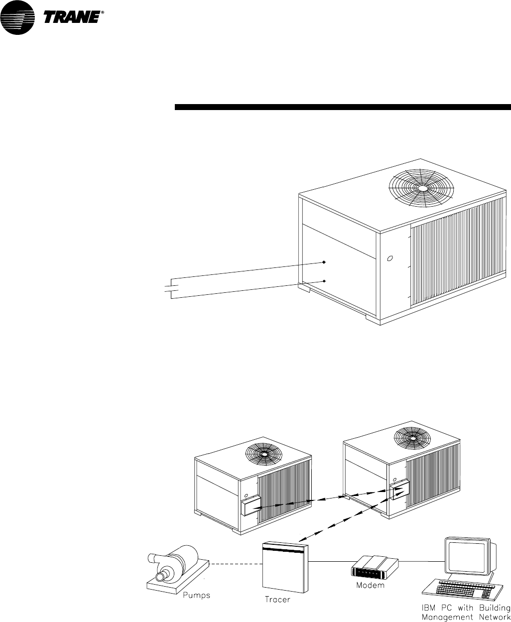
CG-PRC007-EN30
Controls
(Interface with
Other Control
Systems)
Stand-Alone Unit
Interface to stand-alone units is very
simple; only a remote auto-stop or chilled
water flow interlock signal for scheduling
is required for unit operation. Signals
from the chilled water pump contactor
auxiliary or a flow switch are wired to the
chilled waterflow interlock. Signals from a
time clock or some other remote device
are wired to the external auto-stop input.
Unit controls do not provide an output to
turn pumps on and off.
Required Features
1
External Auto/Stop (Standard)
- or -
2
Chilled Waterflow Interlock (Standard)
Trane Integrated Comfort™ System
Interface
A single twisted pair of wires tied directly
between the CGA unit and a Tracer
system provides control, monitoring and
diagnostic capabilities. Control functions
include auto/stop, compressor operation
lockout for kw demand limiting. In
addition, the Tracer system can provide
sequencing control for two or three CGA
units on the same chilled water loop.
Pump sequencing control can be
provided from the Tracer system also.
Sequencing of two CGA’s can be
accomplished with the DDC Chiller
Sequencer.
Required Features
1
Unit Temperature Controller (Standard)
2
ICS Interface Panel
External Trane Devices Required
1
Tracer
Figure C-2 —Tracer ICS System Interface Schematic
Time clock, manual switch or chilled
water pump contactor auxiliary.
Figure C-1 — Stand-Alone Unit
31CG-PRC007-EN
ELECTRICAL CONTROL SYSTEM
The controls used on CGA 10 and 15-ton
units are classified either as “safety”
controls or “operational” controls. Brief
descriptions of the specific safety and
operating controls used in the CGA
control scheme are provided in the
following paragraphs.
Refer to the following control
descriptions for control settings.
UNIT SAFETY CONTROLS
Low Pressure Cutout (LPC01, LPC02)
Mounted below the unit control box are
two low pressure cutouts that open and
stop compressor operation if the
operating pressure drops below 38.5 + 1
psig. The cutout automatically resets
when the pressure reaches 44.5 + 2 psig.
The LPCO is a SPDT device. If it opens at
low ambient start-up, it will energize ODF
relay, stopping the outdoor fan(s) while
the compressor remains energized
through the LAST (Low Ambient Start
Timer).
High Pressure Cutout (HPC01, HPC02)
These units have high pressure cutouts
that open and stop compressor
operation if the discharge pressure
reaches 400 + 10 psig. The cutout
automatically resets when pressure
drops to 250 + 15 psig.
Reset Relays (RRS, RR2)
If the unit is shut down by the low
pressure cutout (or high pressure
cutout), the reset relay locks out the
compressor contactor (CCS, CC2). This
prevents the system from recycling until
the condition that caused the low (or
high) pressure cutout to trip is
determined and corrected.
CAUTION: To prevent unit damage, do
not reset the control circuit until the
cause of the safety lockout is identified
and corrected.
To reset RR1 and RR2, open and reclose
the unit disconnect switch.
Low Temperature Cutout (LTC)
The LTC is designed to disable the unit if
the leaving water temperature falls too
low. The LTC’s remote sensing bulb is
Controls (10, 15 Ton)
mounted at the outlet end of the
evaporator, where it monitors leaving
water temperature.
During normal unit operation, if the low
temperature cutout (LTC) senses a
temperature falling to 36°F + 3.0°F, the
LTC will open to interrupt compressor
operation. (Manual reset is required.)
Motor Overloads
These units have internal compressor
and condenser fan motor overloads.
These overloads protect the motors from
overcurrent and overheating conditions
and automatically reset as soon as they
cool sufficiently.
UNIT OPERATIONAL CONTROLS
Water Temperature Thermostat (WTT)
System operation for 10 and 15-ton CGA
units is governed by a two-stage water
temperature thermostat (WTT). The
remote sensing bulb of this device is
factory-installed in a bulb well located on
the evaporator water inlet; here, it
monitors the temperature of the water
returning to the evaporator.
Low Ambient Start Timer (LAST)
When one of the two timers energizes,
the low pressure control is bypassed for
four minutes, this allows time for suction
pressure to build sufficiently for the low
pressure cutout contacts to close.
Hot Gas Bypass Timer, Solenoid (HGBT,
HGBS)
The hot gas bypass option is factory-
installed only, and is used in a chilled
water system to keep the first stage
compressor on-line during short no-load
or light-load conditions. When Water
Temperature Thermostat (WTT) first
stage opens, 24-volt power is supplied to
the Compressor Contactor (CC1) through
Hot Gas Bypass Timer (HGBT) pins one
and four. Power is also applied from
WTT-B to HGBT coil (fixed 30-minute
time delay pickup) and to the Hot Gas
Bypass Solenoid (HGBS) through HGBT
pins eight and five. If first stage cooling
remains satisfied for 30 minutes, HGBT
will energize and shut down the
compressor. If there is a call for cooling
during HGBP mode, the unit will return
to cooling mode.
The adjustable hot gas bypass valve is
factory set at 70 psig.
Note: Hot gas bypass is available only
on the lead compressor circuit.
Anti-Short Cycle Timers (ASCT1, ASCT2)
An anti-short cycle timer is provided in
each compressor control circuit to
protect the compressors from starting
too frequently. This can occur as a result
of just over 0%, or just over 50% of the
unit capacity, or because of sudden
power outages of short duration.
Whenever the contacts of the water
temperature thermostat (WTT) open —
or when there is a momentary power
outage — the anti-short cycle timer will
lock out compressor operation for three
minutes.
Delay Between Compressors (DBC)
The delay between compressors
prevents both compressors from starting
at the same time by delaying
compressor number two for 30 seconds.
Definition of Abbreviations:
ASCT —Anti-Short Cycle Timer
CC —Compressor Contactor
CWFIR —Chilled Water Flow
Interlock Relay
CWPS —Chilled Water Pump
Starter
DBC —Time Delay Between
Compressors
HGBT —Hot Gas Bypass Timer
HPCO —High Pressure Cutout
LAST —Low Ambient Start
Timer
LPCO —Low Pressure Cutout
LTC —Low Temperature
Cutout
ODF —Outdoor Fan
RR —Reset Relay
SPDT —Single Pole, Double
Throw
WTT —Water Temperature
Thermostat

CG-PRC007-EN32
If compressor number one can’t satisfy
the cooling demand, WTT’s second stage
switch closes, allowing power to pass
through the CWFIR contacts, the DBC,
the ASCT2, the RR2 contacts, the LPC02,
and the HPC02 to energize the CC2 coil.
This starts compressor number two and
outdoor fan number two.
LOW AMBIENT OPERATION
Field Installed Head Pressure Control
Accessory
Standard units will operate in outdoor
ambient temperatures down to the
values shown in the “General Data”
section of this catalog. This accessory
will enable units to operate down to
much lower temperature extremes (see
“General Data” section of this catalog).
Head pressure control for CGA units is
regulated by means of a field-installed
head pressure accessory which varies
condenser fan speed in relation to
discharge pressure.
When discharge pressure is 270 psig or
higher, the condenser fan runs at full
speed. At pressures between 270 psig
and 180 psig, the fan speed is adjusted
(increased or decreased) in direct relation
to the pressure, with minimum fan speed
(10 percent of rated motor rpm)
occurring when the pressure reaches 180
psig. At pressures below 180 psig, the fan
will not run. When discharge pressure
rises to 180 psig, the fan will start and run
at the reduced speed. Fan speed will
continue to increase, as the pressure
increases, until full speed is reached at
270 psig.
SEQUENCE OF UNIT OPERATION
Refer to the unit wiring schematic pasted
to the inside of the control panel cover
when reviewing the control sequence
described below.
Refer to the legend on the previous page
for an explanation of the abbreviations
used in this sequence.
10-Ton Operation
With fused disconnect switch closed,
power is supplied to the crankcase
heaters and the 24-volt control circuit.
Starting the chilled water pump closes
the CWPS auxiliary contacts and
completes the flow switch.
When the water temperature rises above
the WTT’s set point, its first stage switch
closes, allowing power to pass through
CWPS auxiliary contacts, the flow switch,
the LTC, the ASCT1, the RR1 contacts, the
LPC01, and the HPC01 to energize the
CC1 coil. This starts compressor number
one and the outdoor fan.
If compressor number one can’t satisfy
the cooling demand, WTT’s 2nd stage
switch closes, allowing power to pass
through the CC1 auxiliary contacts, the
DBC, the ASCT2, the RR2 contacts, the
LPC02, and the HPC02 to energize the
CC2 coil which starts compressor
number two.
15-Ton Operation
With fused disconnect switch closed,
power is supplied to the crankcase
heaters, and the 24-volt control circuit.
Starting the chilled water pump closes
the CWPS auxiliary contacts and
completes the flow switch, allowing
power to pass through the LTC to
energize the CWFIR.
When the water temperature rises above
the WTT’s set point, its first stage switch
closes, allowing power to pass through
the CWFIR contacts, the ASCT1, the RR1
contacts, the LPC01, and the HPC01 to
energize the CC1 coil. This starts
compressor number one and outdoor
fan number one.
Controls (10, 15 Ton)
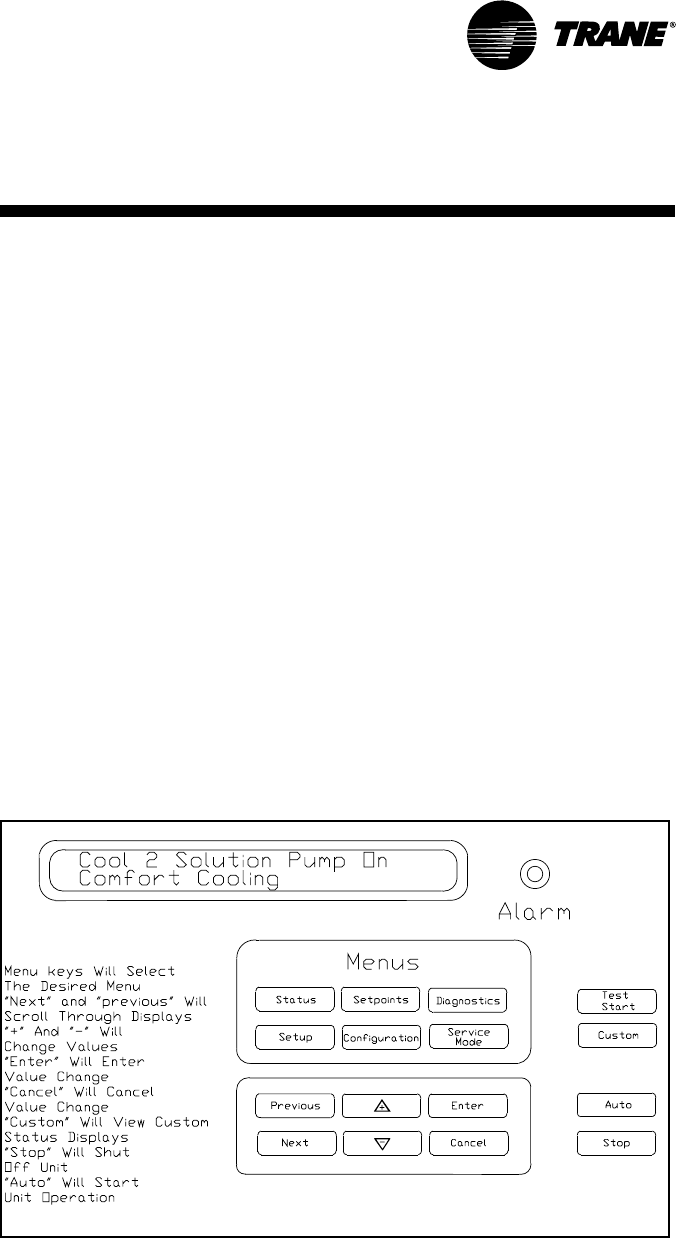
33CG-PRC007-EN
Simple Interface with All Control
Systems
The IntelliPak controls afford simple
interface with Trane Tracer™ systems,
providing broad control capabilities for
Building Automation systems.
For control systems other than Trane, two
generic building automation system
interfaces are available and offer
simplicity and flexibility in accessing unit
functions.
Safety Controls
A centralized microcomputer offers a
higher level of machine protection. Since
the safety controls are smarter, they limit
compressor operation to avoid
compressor or evaporator failures,
thereby minimizing nuisance shutdown.
For instance, the Unit Control Module
(UCM) will provide condenser low
Customized Control
With IntelliPak controls, Trane can
customize controls around the chiller
application and the specific components
used in the CGAF.
For instance, the compressor protection
system is specifically designed for the
Trane 3-D™ Scroll compressor. A leaving
chilled solution temperature control
algorithm maintains accurate
temperature control, for both comfort
and process applications, minimizing the
drift from set point.
The IntelliPak controls incorporate
improved chiller start-up, load limiting,
compressor anti-recycle timing and lead/
lag functions into standard chiller
operation. Interface with outside systems
such as building automation controls is
flexible and easy.
pressure control by staging condenser
fans on or off in an effort to maintain
the saturated condensing temperature
within a fixed range. Overall, the safety
controls help keep the cooling system
on-line and operating safely.
Monitoring and Diagnostics
Since the microcomputer provides all
control functions, it can easily indicate
such parameters as leaving chilled
solution temperature and capacity
staging. If a failure does occur, the
diagnostic alarm will be displayed
giving specific information about the
failure. All of the monitoring and
diagnostic information can be easily
accessed at the Human Interface
display, standard on every unit.
Figure C-3 — Human Interface Display
Controls (20–60 Ton)

CG-PRC007-EN34
Standard Control Features
Human Interface (HI) Panel
The Human Interface (HI) Panel provides
a 2 line X 40 character clear English
language liquid crystal display and a 16
button keypad for monitoring, setting,
editing and controlling. The Human
Interface Panel is mounted in the unit’s
main control panel and is accessible
through a hatch built into the unit’s
control panel door.
The optional remote-mounted version of
the Human Interface panel has all the
functions of the unit-mounted HI, with
the exception of the Service Mode. To
use a Remote Human Interface (RHI), the
unit must be equipped with an optional
InterProcessor Communications Bridge
(IPCB). The RHI can be located up to
5,000 feet from the unit. A single RHI can
be used to monitor and control up to 4
chillers, each containing an IPCB.
The Main Menu of the Human
Interface panel:
STATUS — used to monitor all
temperatures, pressures, set points,
input and output status. The CUSTOM
KEY will have four reports that can be
user defined. The report screens consist
of the data available in the main status
menu.
SET POINTS — used to edit all factory
preset default set points and assign set
point sources.
DIAGNOSTICS — used to review active
and historical lists of diagnostic
conditions. A total of 41 different
diagnostics can be read at the Human
Interface Panel. The last 20 diagnostics
can be held in an active history buffer log
at the Human Interface Panel.
SETUP — Control parameters, sensor
selections, set point source selections,
output definitions, and numerous other
points can be edited from this menu. All
points have factory preset values so
unnecessary editing is kept to a
minimum.
CONFIGURATION — Preset with the
proper configuration for the unit as it
ships from the factory, this information
would be edited only if certain features
were physically added or deleted from
the unit. For example, if a field supplied
Trane Communication Interface (TCI)
module was added to the unit in the
field, the unit configuration would need
to be edited to reflect that feature.
SERVICE — used to selectively control
outputs (for compressors, fans, etc.)
when servicing or troubleshooting the
unit. This menu is accessible only at the
unit-mounted Human Interface Panel.
STOP, AUTO — when the chiller is in the
stop mode, pressing the AUTO KEY will
cause the UCM to go into either the
Auto/Local or Auto/ICS mode, depending
on the set point source setting.
Chiller Capacity Control — The Unit
Control Module (UCM) will control
leaving solution temperature to a user
adjustable set point. The UCM monitors
the leaving solution temperature sensor
and determines how far away this
temperature is from the leaving solution
set point and how long it has been there.
The rate at which capacity stages are
added or subtracted is determined by a
control integrator algorithm. This
algorithm calculates a control integrator
value based upon the inputs from the
control response set point, the difference
between the leaving solution set point
and the leaving solution temperature,
the number of capacity steps, and the
design delta temperature. This function
can be user defined for comfort or
process control applications. The
following set points are integrated into
the capacity control algorithm:
Leaving Solution Set point (LSS) — The
LSS is adjustable from the factory as
standard within a range from 40-50°F.
Three other possible ranges can be
selected and ordered from the factory,
20-29, 30-39°, and 51-65°F. When these
options are selected, the unit hardware
changes to allow the unit to operate
under safe conditions.
Design Delta Temperature set point —-
the design delta T drop within the
evaporator is adjustable from 4-20 °F in
one degree increments. In addition, the
control response set point can affect the
speed of the UCM’s response to
changing cooling requirements. This
value can be set through the HI to allow
flexibility in maintaining precise control
conditions.
Chiller Freeze Protection — The
microprocessor will prevent the
evaporator fluid from freezing by
reducing chiller capacity, ultimately
shutting down all compressors and
sending a manually re-settable
diagnostic. The inputs for freeze
protection are the low leaving solution
temperature cutout and the leaving
solution temperature.
Evaporator Solution Flow Interlock —
The IntelliPak control requires an
external evaporator flow switch interlock.
An external field installed flow switch
must be wired into the unit terminal
strip. When an open condition is
detected for six (6) seconds or longer, the
compressors will shut down and after
five (5) minutes an automatic resettable
diagnostic alarm will be sent.
(20–60 Ton
Interface)Controls

35CG-PRC007-EN
Head Pressure Control — Condenser
head pressure control is provided in the
UCM by staging condenser fans on or
off to maintain the saturated condensing
temperature. This function will allow
cooling operation down to 30°F as
standard. Minimum on and off timing is
built into the algorithm to prevent rapid
cycling.
Pump down — This feature can be
enabled or disabled through the Human
Interface. When it is enabled, pump
down will be initiated prior to shutting
down the last capacity stage on each
circuit by de-energizing a liquid line
solenoid valve. Pump down is
terminated by the opening of the low
pressure switch, or 30 seconds after the
cycle is initiated. On units equipped with
hot gas bypass, pump down will be
initiated upon termination of the hot gas
bypass cycle.
Chiller Solution Pump Control — The
UCM has two operating modes for the
chiller solution pump control, Auto and
On. The UCM additionally has a relay
output that will energize/de-energize the
chiller’s solution pump control circuit.
The relay is de-energized, stopping the
pump, when emergency stop is
activated. The solution pump relay is
energized to run the pump in the
following modes: freeze protection,
normal cooling control, low ambient
freeze protection, ice building and loop
stabilization, and service mode. Modes
that will request the pump to stop are ice
building complete, ice building delay,
unit stop and external auto/stop.
Low Ambient Start Control — Two
functions are integrated into the control
to allow operation in extreme conditions
and still protect the overall system. Low
ambient start control will allow
compressor operation below 65°F. In
order to avoid nuisance tripping, the low
pressure control will be bypassed for a
period of time. If the low pressure
control is still open at the end of the
period, the compressor is shut down and
the solenoid valve is opened. The loss of
refrigerant flow protection is active in
this sequence to additionally protect the
chiller.
Hot Start Control — A high ambient start
sequence will permit only one
compressor to operate when the leaving
solution temperature is in the user
adjustable range of 60-80°F. When the
leaving solution temperature falls below
this high limit, the second compressor
will be active.
Low Ambient Compressor Lockout —
This function will lock out the
compressor if the outdoor air
temperature is below the low ambient
compressor lock out temperature set
point. This set point is adjustable at the
Human Interface Panel (HI) between 0-
60°F. Compressors will be locked out
when outdoor air temperatures fall
below that selected temperature and will
be allowed to start again when the
temperature rises 5° F above the set
point.
Compressor Lead/Lag — Compressor
lead/lag is a user-selectable feature
through the Human Interface Panel
available on all units. When enabled, the
algorithm in the UCM will start
compressors based upon the least
number of starts and/or run time. This
feature is not available with the hot gas
bypass option.
Emergency Stop Input — A binary input
is provided on the Unit Control Module
(UCM) for installation of field provided
switch or contacts for immediate
shutdown of all unit functions.
External Auto/Stop — A set of contacts
or switches can be field installed that will
start and stop the chiller.
Demand Limit — The UCM will accept an
input from a field installed device which
will prevent one or more compressors
from operating. The user can select the
number of compressors to be turned off.
Leaving Solution Reset — This flexible
option allows active leaving solution
reset based on customer selectable
inputs from the zone, entering solution
temperature or outside air temperature.
When the application is sensitive to one
of these parameters, subcooling of
critical zones is prevented.
Optional Control Features
Compressor Current Sensing — This
option will measure and average the
amp draw of 2 phases of each
compressor.
Superheat/Subcooling Option — This
option will include the necessary
temperature and pressure sensors to
measure and calculate the chiller’s
superheat and subcooling numbers for
each circuit. These temperatures and
pressures, along with calculated values
of superheat/subcool, will be displayed
in the status menu of the Human
Interface. No external refrigerant gauges
need to be installed on the chiller for the
system operator to check out these
conditions.
External Leaving Solution Set point —
Remote set point potentiometer can be
ordered to allow adjustment of the
leaving solution set point remotely.
(20–60 Ton
Interface)Controls

CG-PRC007-EN36
Generic Building Automation System
Module (GBAS) — Two Generic
Building Automation System Modules
(GBAS) are available as an option to
provide broad control capabilities for
building automation systems, other than
the Trane’s Tracer system.
The 0-5 vdc input GBAS Module
contains 4 analog inputs, one binary
input for demand limit, and 5 binary
outputs.
The 4 analog inputs can accept a 0-5 vdc
or a three wire potentiometer signal and
be assigned to:
1. Leaving Solution Set point
2. Ice Build Terminate Set point
3. Hot Start Load Limit Set point
4. Maximum Capacity Level
Set point
The 5 binary outputs can be assigned:
1. Active Unit Diagnostics
2. Compressor running status
3. Maximum Capacity (all
compressors running)
4,5. Open - Diagnostics can be
grouped or individually assigned
by the user and may be placed
in these outputs.
The 0-10 vdc input GBAS module
contains 4 analog inputs, one binary
input for demand limit, four analog
outputs and one binary output.
The 4 analog inputs can accept a 0-10
vdc signal and be assigned to:
1. Leaving Solution Set point
2. Ice Build Terminate Set point
3. Hot Start Load Limit Set point
4. Maximum Capacity Level Set point
The 4 analog outputs can be assigned
to:
1. Leaving Solution Temperature
2. Entering Solution Temperature
3. Saturated Condenser Temp.
Ckt 1, 2
4. Evaporator Temp. Ckt 1, 2
5. Liquid Line Pressure Ckt1, 2
6. Suction Pressure Ckt 1, 2
7. Actual Capacity Level
8. Outdoor Air Temperature
One binary output can be assigned to:
1. Active Unit Diagnostics
2. Compressors Running Status
3. Max Capacity
Hot Gas Bypass (HGBP) — The HGBP
control allows unit operation below the
minimum step of unloading. Hot gas
bypass is initiated when the last capacity
step is running and the capacity control
algorithm generates a subtract
command. HGBP remains energized
until the load increases, the chiller freeze
protection function is activated, a user
defined run time has expired, the low
pressure control is open, or the unit goes
into ice building mode.
Alarm and Max Capacity Relay — These
features are user selectable and are
mutually exclusive of each other. If the
alarm relay output is selected, it will
provide a way to trigger a field supplied
alarm whenever the UCM detects a fault
requiring manual reset. The customer
can assign which fault modes will trigger
the alarm relay. The alarm will
de-energize when the manual reset is
cleared. When Max Capacity Output is
selected, it will trigger a field installed
device indicating the unit has reached its
maximum cooling stage; this gives the
customer the ability to turn on auxiliary
systems to manage comfort.
Ice Building Control — A contact closure
on the UCM allows either a field installed
device or an ICS system to initiate the
unit to operate in the ice building mode.
In this mode normal chiller temperature
control is bypassed and the unit runs
fully loaded until ice building is
complete. There are two optional ice
building modes that can be selected
through the HI. Ice building is
terminated when the customer provide
contacts are opened, Ice Building Stop is
initiated from the Tracer, or the entering
solution temperature reaches or drops
below the ice building terminate set
point.
Option 1 - One time Ice building mode
allows the unit to run fully loaded until
the entering solution temperature falls to
the active ice building terminate set
point (IBTS) When the entering solution
temperature reaches the terminate set
point, the unit will go through
pumpdown if enabled and remain in Ice
Complete standby mode until the ice
build mode is terminated.
Option 2 - Continuous ice build mode
allows the unit to run fully loaded until
the entering solution temperature falls to
the active ice building terminate set
point (IBTS). When the entering solution
temperature reaches the terminate set
point, the unit will go through
pumpdown if enabled, and remain in Ice
build delay. The unit will remain in ice
build standby until the ice build timer
expires. The unit will then start the pump
and wait for the loop stabilization timer
to expire. The unit will run fully loaded
until the entering solution temperature
falls below the ice build termination set
point. The unit will continue cycling
through these ice building states until
the Ice build mode is terminated or
changed to option 1.
(20–60 Ton
Interface)Controls
37CG-PRC007-EN
Table ED-1 — Electrical Data
Unit Wiring Motor Data
Model Nameplate Voltage Max Fuse Rec. Dual Compressor (Ea) Fans (Ea)
Tons Number Voltage Range MCA Size Element Qty. RLA LRA Qty KW FLA
CGA120B1 208-230/60/1 187-254 74 100 2 30.0 169 1 .95 6.0
CGA120B3 208-230/60/3 187-254 38.4 50 2 14.4 128 1 .95 6.0
10 CGA120B4 460/60/3 414-506 24.1 30 2 9.5 63 1 .95 2.7
CGA120BW 575/60/3 518-632 18.4 25 2 7.3 49 1 .95 2.0
CGA180B3 208-230/60/3 187-254 66 90 2 26.6 208 2 1.03 3.1
15 CGA180B4 460/60/3 414-506 35 45 2 14.3 91 2 1.03 1.6
CGA180BW 575/60/3 518-632 28 35 2 11.3 68 2 1.03 1.2
200/60/3 180-220 98 125 110 2 39.4 269 2 0.9 4.1
230/60/3 208-254 98 125 110 2 39.4 251 2 0.9 4.1
20 CGAF-C20 460/60/3 416-508 44 60 50 2 17.2 117 2 0.9 1.8
575/60/3 520-635 33 45 40 2 13.2 94 2 0.9 1.4
200/60/3 180-220 124 175 150 2 39.3,56.9 269,409 3 0.9 4.1
230/60/3 208-254 124 175 150 2 39.3,56.9 251,376 3 0.9 4.1
25 CGAF-C25 460/60/3 416-508 56 80 70 2 17.1,25.4 117,178 3 0.9 1.8
575/60/3 520-635 44 60 50 2 13.8,20.2 94,143 3 0.9 1.4
200/60/3 180-220 146 200 175 2 56.9 409 4 0.9 4.1
230/60/3 208-254 146 200 175 2 56.9 376 4 0.9 4.1
30 CGAF-C30 460/60/3 416-508 65 80 80 2 25.1 178 4 0.9 1.8
575/60/3 520-635 51 70 60 2 19.9 143 4 0.9 1.4
200/60/3 180-220 187 225 200 4 39.4 269 4 0.9 4.1
230/60/3 208-254 186 225 200 4 39.4 251 4 0.9 4.1
40 CGAF-C40 460/60/3 416-508 82 90 90 4 17.2 117 4 0.9 1.8
575/60/3 520-635 62 70 70 4 13.2 94 4 0.9 1.4
200/60/3 180-220 224 250 250 4 35.5,55.5 269,409 6 0.9 4.1
230/60/3 208-254 223 250 250 4 35.5,55.5 251,376 6 0.9 4.1
50 CGAF-C50 460/60/3 416-508 98 110 110 4 15.5,24.2 117,178 6 0.9 1.8
575/60/3 520-635 77 90 90 4 12.4,19.4 94,143 6 0.9 1.4
200/60/3 180-220 270 300 300 4 56.9 409 6 0.9 4.1
230/60/3 208-254 269 300 300 4 56.9 376 6 0.9 4.1
60 CGAF-C60 460/60/3 416-508 120 125 125 4 25.4 178 6 0.9 1.8
575/60/3 520-635 95 110 100 4 20.2 143 6 0.9 1.4
Notes:
1. MCA: Minimum Circuit Ampacity is 125% of the largest compressor RLA, plus 100% of the other compressor(s) RLA, plus the sum of the condenser fan FLA, plus any other
load rated at 1 AMP or more
2. Maximum Fuse Size: 225% of the largest compressor RLA, plus 100% of the other compressor(s) RLA, plus the sum of the condenser fan FLA, plus any other load rated at 1
AMP or more
3. Recommended Dual Element Fuse Size: 150% of the largest compressor RLA plus 100% of the other compressor(s) RLA plus the sum of the condenser fan FLA plus any
other load rated at 1 AMP or more.
4. RLA: Rated in accordance with UL standard 1995.
5. Local codes may take precedence.
6. All units are across the line starting. Compressors will never start simultaneously.
7. One 115/60/1, 15 AMP jobsite provided power connection is required to operate the evaporator heat tape.
Load Definitions
LOAD1 = Current of the largest motor —
compressor or fan motor
LOAD2 = Sum of the currents of all
remaining motors
LOAD3 = Current of electric heaters
LOAD4 = Any other load rated at 1 amp
or more
MCA = (1.25 x LOAD1) + LOAD2 +
LOAD4
MOP = (2.25 x LOAD1) + LOAD2 +
LOAD4
Electrical
Data - 60 HZ
Select a fuse rating equal to the MOP
value. If the MOP value does not equal a
standard fuse size as listed in NEC 240-6,
select the next lower standard fuse
rating.
NOTE: If selected MOP is less than the
MCA, then reselect the lowest standard
maximum fuse size which is equal to or
larger than the MCA, provided the
reselected fuse size does not exceed 800
amps.
RDE = (1.5 x LOAD1) + LOAD2 +
LOAD4
Select a fuse rating equal to the RDE
value. If the RDE value does not equal a
standard fuse size as listed in NEC 240-6,
select the next higher standard fuse
rating.
NOTE: If the selected RDE is greater than
the selected MOP value, then reselect
the RDE value to equal the MOP value.
DSS = 1.5 x (LOAD1 + LOAD2 +
LOAD3 + LOAD4)
Select a disconnect switch size equal to
or larger than the DSS value calculated.
(10–60 Ton)
CG-PRC007-EN38
Table ED-2 — Electrical Data
Unit Wiring Motor Data
Model Nameplate Voltage Max Fuse Rec. Dual Compressor (Ea) Fans (Ea)
Tons Number Voltage Range MCA Size Element Qty. RLA LRA Qty KW FLA
10 CGA100BD 380-415/50/3 342-456 24.1 30 —2 9.5 63 1 0.57 2.7
15 CGA150BD 380-415/50/3 342-456 30.0 40 —2 11.9 91 2 0.33 1.6
20 CGAF-C20 380/50/3 342-418 44 60 50 2 17.2 110 2 0.75 1.7
415/50/3 373-456 44 60 50 2 17.2 110 2 0.75 1.7
25 CGAF-C25 38050/3 342-418 55 80 70 2 17.3/25.2 110/174 3 0.75 1.7
415/50/3 373-456 55 80 70 2 17.3/25.2 110/174 3 0.75 1.7
30 CGAF-C30 380/50/3 342-418 65 80 80 2 25.2 174 4 0.75 1.7
415/50/3 373-456 65 80 80 2 25.2 174 4 0.75 1.7
40 CGAF-C40 380/50/3 342-418 81 90 90 4 17.2 110 4 0.75 1.7
415/50/3 373-456 81 90 90 4 17.2 110 4 0.75 1.7
50 CGAF-C50 380/50/3 342-418 97 110 110 4 15.5/24.2 110/174 6 0.75 1.7
415/50/3 373-456 97 110 110 4 15.5/24.2 110/174 6 0.75 1.7
60 CGAF-C60 380/50/3 342-418 119 125 125 4 25.2 174 6 0.75 1.7
415/50/3 373-456 119 125 125 4 25.2 174 6 0.75 1.7
Notes:
1. MCA: Minimum Circuit Ampacity is 125% of the largest compressor RLA, plus 100% of the other compressor(s) RLA, plus the sum of the condenser fan FLA, plus any other
load rated at 1 AMP or more.
2. Maximum Fuse Size: 225% of the largest compressor RLA, plus 100% of the other compressor(s) RLA, plus the sum of the condenser fan FLA, plus any other load rated at 1
AMP or more.
3. Recommended Dual Element Fuse Size: 150% of the largest compressor RLA, plus 100% of the other compressor(s) RLA, plus the sum of the condenser fan FLA, plus any
other load rated at 1 AMP or more.
4. RLA: Rated in accordance with UL standard 1995.
5. Local codes may take precedence.
6. Control kw includes operational controls only. Does not include evaporator heat tape.
7. All units are across the line starting. Compressors will never start simultaneously.
8. One 240/50/1, 5 AMP jobsite provided power connection is required to operate the evaporator heat tape.
(10–60 Ton)Electrical
Data - 50 HZ
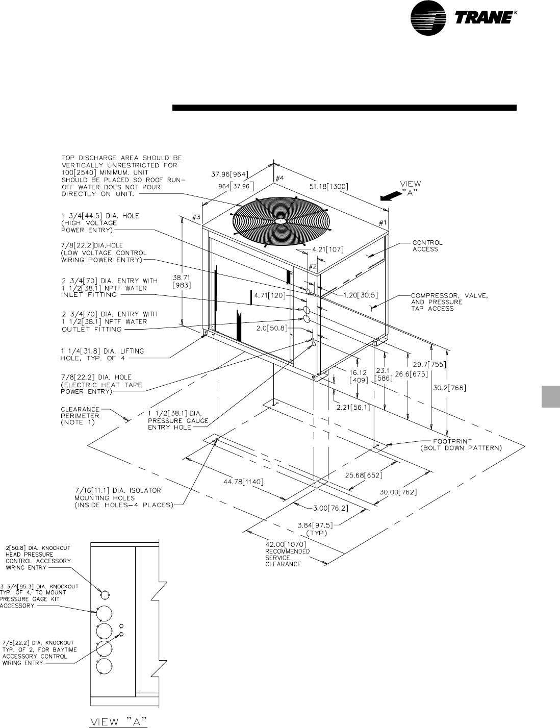
39CG-PRC007-EN
Dimensional
Data
Figure DD-1 — CGA-120B Unit Dimensions
(10 Ton)
Notes:
1. Minimum clearance around the perimeter of the unit is 3 feet. Minimum clearance between
adjacent units is 6 feet.
2. When installing water pipes, be certain to route them away from the compressor access panels
to allow for compressor servicing or replacement.
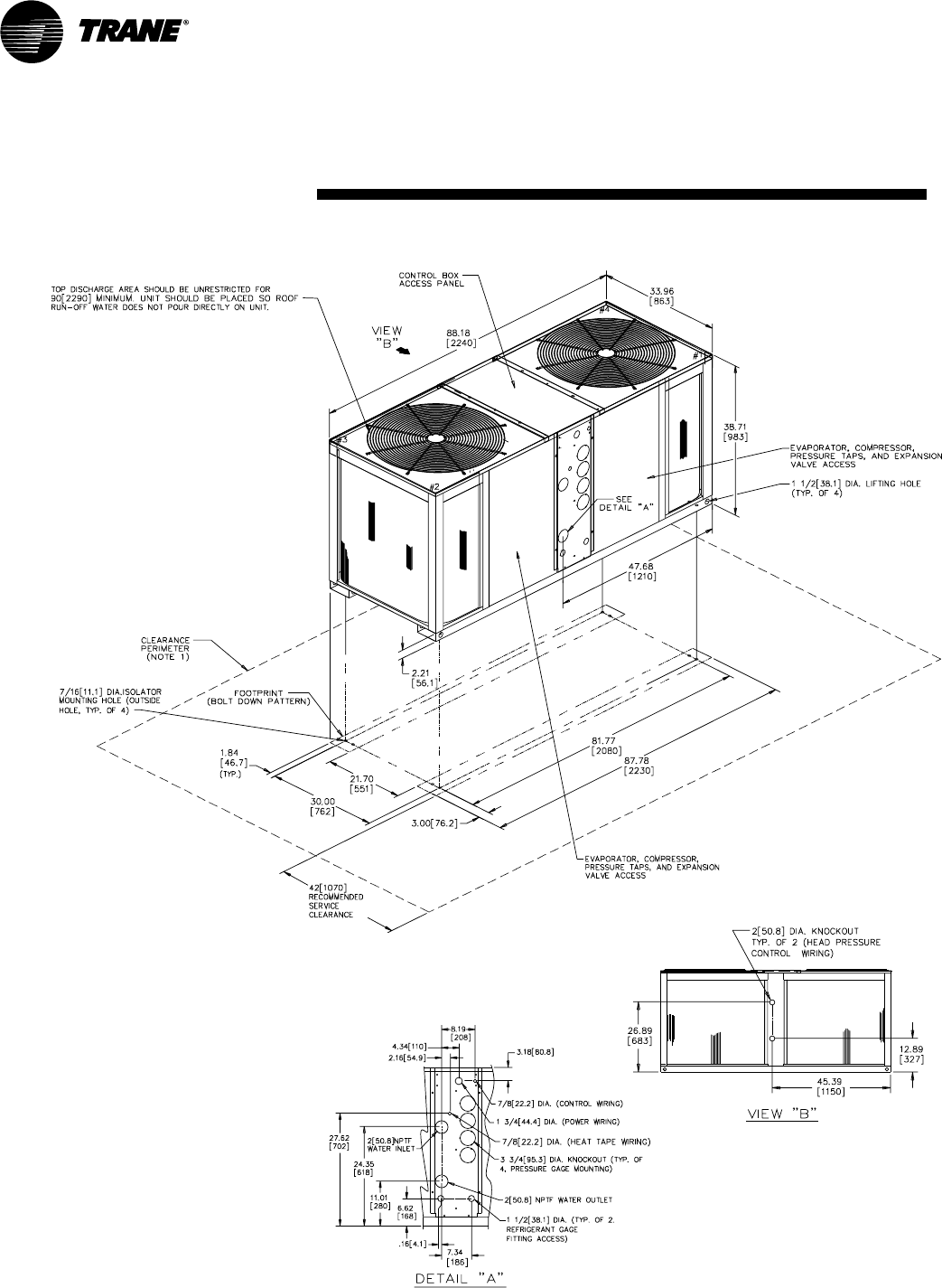
CG-PRC007-EN40
Dimensional
Data
Figure DD-2 — CGA-180B Unit Dimensions
(15 Ton)
Notes:
1. Minimum clearance around the perimeter of the unit is 3 feet. Minimum clearance between
adjacent units is 6 feet.
2. When installing water pipes, be certain to route them away from the compressor access panels
to allow for compressor servicing or replacement.
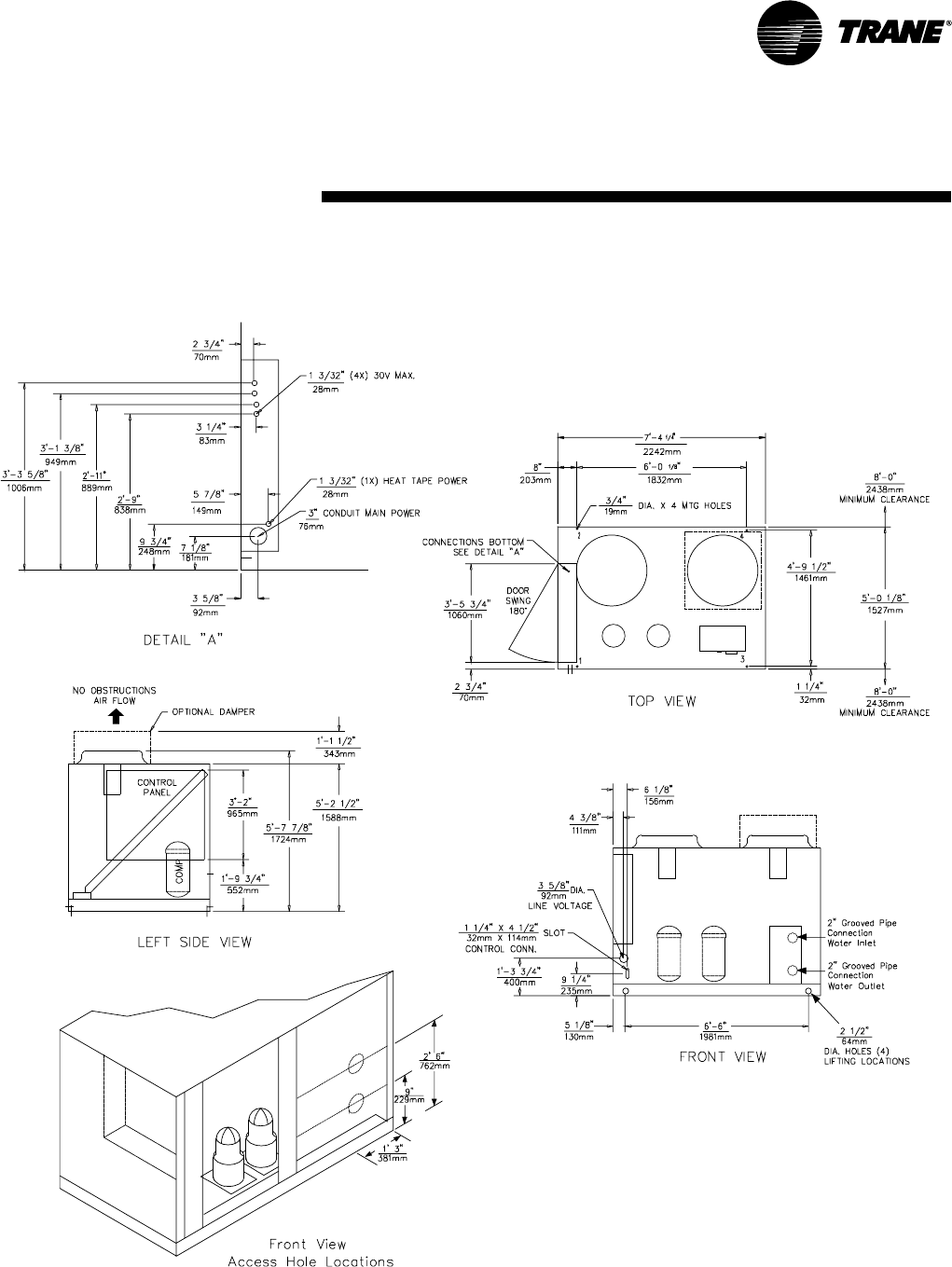
41CG-PRC007-EN
Dimensional
Data
Figure DD-3 — CGAF-C20 Unit Dimensions
(20 Ton)
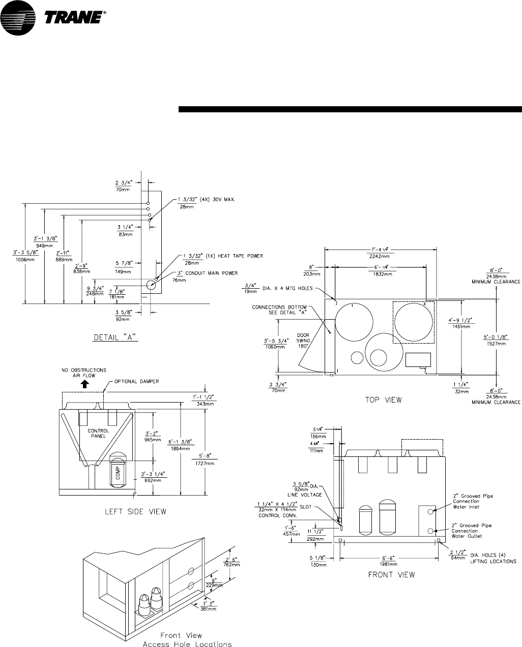
CG-PRC007-EN42
Dimensional
Data
Figure DD-4 — CGAF-C25 Unit Dimensions
(25 Ton)
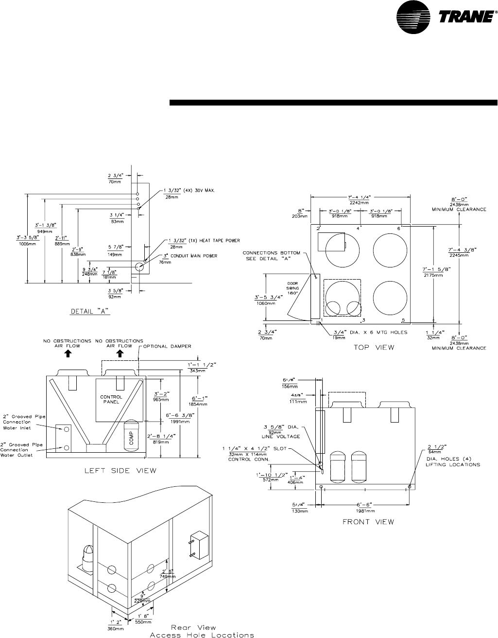
43CG-PRC007-EN
Dimensional (30 Ton)
Data
Figure DD-5 — CGAF-C30 Unit Dimensions
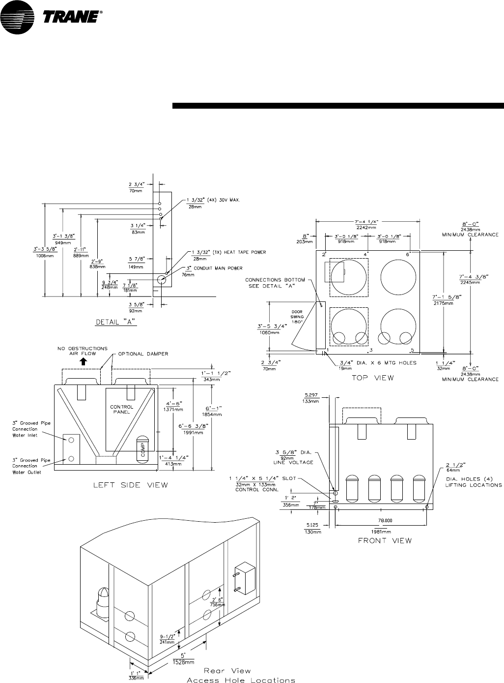
CG-PRC007-EN44
Dimensional (40 Ton)
Data
Figure DD-6 — CGAF-C40 Unit Dimensions
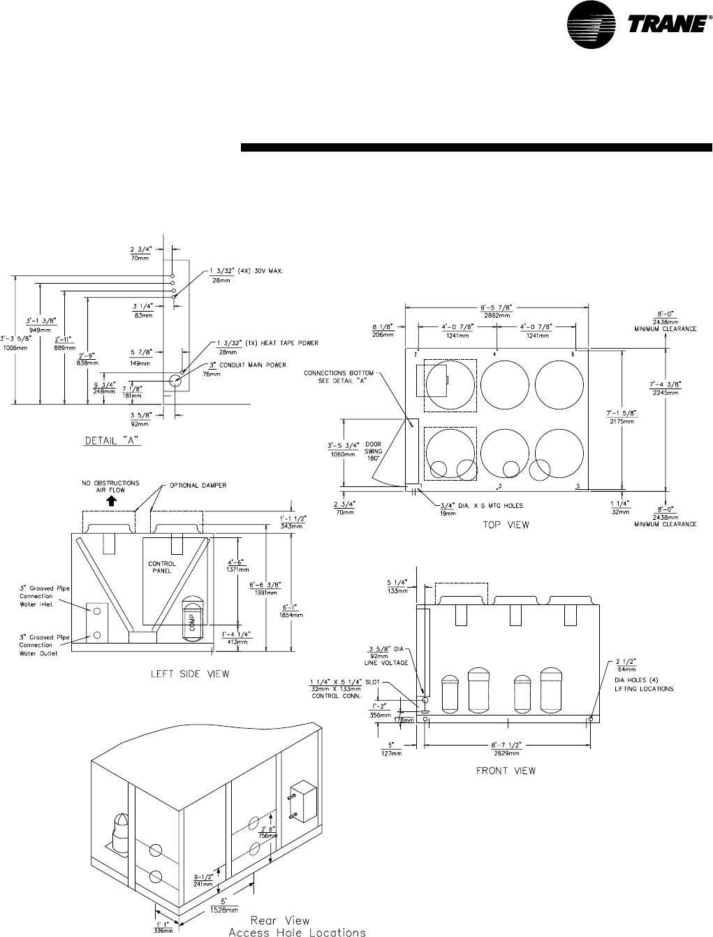
45CG-PRC007-EN
Dimensional (50 Ton)
Data
Figure DD-7 — CGAF-C50 Unit Dimensions
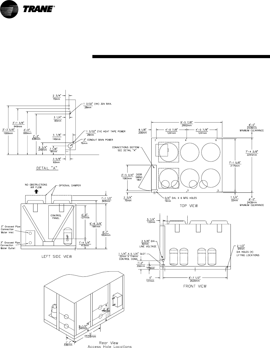
CG-PRC007-EN46
Dimensional (60 Ton)
Data
Figure DD-8— CGAF-C60 Unit Dimensions
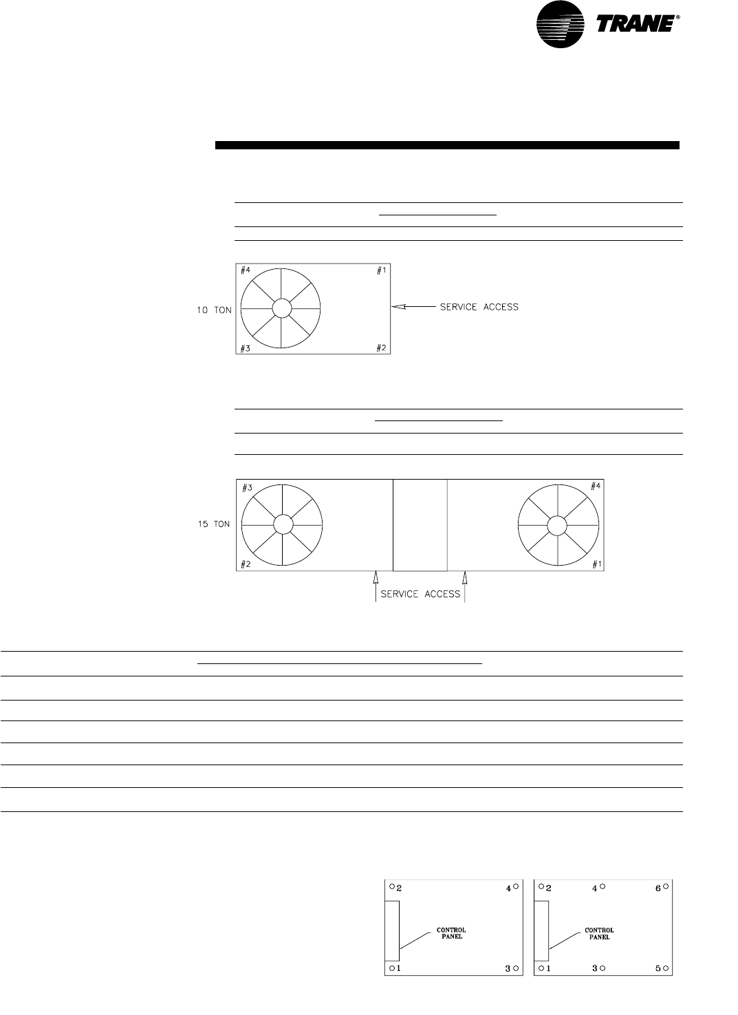
47CG-PRC007-EN
Weights
Table W-1 — Approximate Corner Weights (lbs) 10-Ton Unit
Isolator Loading
Tons Model Number 1 2 3 4 Operating Wt. Shipping Wt.
10 CGA 120B 161 164 103 101 529 576
Table W-2 — Approximate Corner Weights (lbs) 15-Ton Unit
Isolator Loading
Tons Model Number 1 2 3 4 Operating Wt. Shipping Wt.
15 CGA 180B 186 187 208 207 788 871
Table W-3 — CGAF Unit Weights (lbs)
Model Condenser Isolator Loadings Location (lbs) Operating Shipping
TonsNumberFin Type123456 Weight (lbs)Weight (lbs)
Aluminum 595 470 470 335 —— 1870 1875
Copper 690 475 490 430 —— 2085 2095
Aluminum 700 470 490 425 —— 2085 2085
Copper 760 540 580 490 —— 2370 2370
Aluminum 865 430 725 340 430 270 3060 3065
Copper 875 525 830 385 555 280 3450 3455
Aluminum 560 580 580 595 480 495 3290 3290
Copper 570 755 605 540 640 570 3680 3675
Aluminum 685 715 720 750 505 525 3900 3900
Copper 840 870 660 680 680 705 4435 4435
Aluminum 885 820 855 985 620 720 4885 4865
Copper 935 1220 875 920 1010 860 5820 5800
Notes:
1. Operating weights include refrigerant and water, but do not include weight of accessories.
2. Shipping weights include refrigerant and crating.
3. Refer to dimensional data for location of isolator loading points.
30 CGAFC30
40 CGAFC40
50 CGAFC50
60 CGAFC60
25 CGAFC25
20 CGAFC20
20-25 Tons 30-60 Tons
(10–60 Ton)

CG-PRC007-EN48
Mechanical
Specifications
(10–15 Ton)
General
Units shall be assembled on heavy
gauge steel mounting/lifting rails and
shall be weatherproofed. Units shall
include hermetic scroll compressors,
plate fin condenser coil, fan(s) and
motor(s), controls and complete factory
installed operating charge of oil and
R-22 refrigerant. Operating range shall
be between 115°F and 0°F. Units shall be
either UL or CSA certified and rated in
accordance with ARI Standard
550/590-98.
Casing
Unit casing shall be constructed of
18-gauge zinc coated heavy gauge,
galvanized steel. Exterior surfaces shall
be cleaned, phosphatized and finished
with a weather-resistant baked enamel
finish. Units surface shall be tested to
withstand a 500 consecutive hour salt
spray durability test. Units shall have
removable panels which allow access to
major components and controls.
Refrigeration System
Unit shall have two separate and
independent refrigeration circuits. Each
refrigeration circuit shall have integral
subcooling circuits. Refrigeration filter
driers and sight glasses shall be
provided as standard.
Compressors
Unit shall have two Trane direct-drive
hermetic scroll compressors with
centrifugal oil pump and provide
positive lubrication to all moving parts.
Motor shall be suction gas-cooled and
shall have a voltage utilization range of
plus or minus 10 percent of nameplate
voltage. Crankcase heater, internal
temperature and current-sensitive
motor overloads shall be included for
maximum protection. External high and
low pressure cutout devices shall be
provided.
Condenser Coil
Coils shall be 3/8” copper tubes
mechanically bonded to configured
aluminum plate fin as standard. Factory
pressure and leak tested to 420 psig
minimum air pressure and design
working pressure shall be 376 psig.
Metal grilles with PVC coating for coil
protection are optional.
Evaporator
The evaporator shall have independent
dual refrigerant circuits. The evaporator
shall be stainless steel braze plate
construction with a waterside working
pressure of 350 psig and a refrigerant-
side working pressure of 300 psig. One
water pass with a drain connection.
Condenser Fan and Motor(s)
Direct-drive, statically and dynamically
balanced propeller fan(s) with aluminum
blades and electro-coated steel hubs
shall be used in draw-thru vertical
discharge position. Either permanently
lubricated totally enclosed or open
construction motors shall be provided
and shall have built-in current and
thermal overload protection. Motor(s)
shall be ball bearing type.
Controls
The chiller shall be completely factory
wired with necessary controls and
contactor pressure lugs or terminal block
for power wiring. Control wiring shall be
24-volt control circuit which includes
fusing and control transformer. Time
delay timers to prevent compressors in
dual compressor units from
simultaneous start-up and anti-recycle
timers shall be standard.
Low Ambient Operation
Standard units shall start and operate to
approximately 50°F. Optional head
pressure control accessory permits
operation at lower temperature
extremes (see “General Data” section of
this catalog).
OPTlONS
Field Installed
Low Ambient Head Pressure Control
Shall modulate the rpm of unit outdoor
fan motor in response to unit head
pressure. Accessory provides unit
cooling operation to outdoor
temperatures of 0°F.
Vibration Isolation Packages
Shall reduce transmission of noise and
vibration to building structures,
equipment and adjacent spaces.
Packages shall be available in either
neoprene-in-shear or spring-flex types.
Condenser Coil Guard
Metal grille with PVC coating shall be
provided to alleviate coil damage.
Power Supply Monitor
Shall provide protection against phase
loss/reversal, phase imbalance, incorrect
phase sequence and low voltage.
Elapsed Time Meter/Number Starts
Counter
Shall record number of compressor
starts and operating hours of each
compressor.
Integrated Comfort Systems (ICS)
Interface
Shall provide the ability to communicate
with the Trane Tracer building
management system via TCM.
Flow Switch
Required as a safety interlock to prevent
operation of unit without evaporator
flow.
Gauges
Field-installed gauges monitor suction
and discharge pressures.
Factory Installed
Black Epoxy Coil
The black epoxy coating provides
excellent protection against aluminum
corrosion.
Hot Gas Bypass
Allows unit operation below the
minimum step of unloading.
Low Leaving Solution Temperature
Applications
Allows leaving solution temperatures as
low as 20°F. This capability is standard
from the factory on both 10 and 15-ton
models.

49CG-PRC007-EN
Mechanical
Specifications
(20–60 Ton)
GENERAL
All chillers are factory run-tested to
confirm proper operation. Units are
checked on a computer-based test stand
at typical ambient and water conditions
and control operation is monitored.
Units ship with a full operating charge of
refrigerant and oil.
Units are constructed of 14-gauge
welded galvanized steel frame with 14
and 16-gauge galvanized steel panels
and access doors. Unit surface is
phosphatized and finished with an air-
dry paint. This air-dry paint finish is
durable enough to withstand a 1000-
consecutive-hour salt spray application
in accordance with standard ASTM B117.
Evaporator
Braze plate construction designed to
withstand a waterside working pressure
of 300 psig and a refrigerant side
working pressure of 225 psig. It has one
water pass. Etched foil heaters protect
the evaporator to an ambient of -20°F.
Flow Switch
This factory supplied item indicates the
loss of evaporator flow and ships with
the unit for field installation.
Strainer (with installation hardware)
The strainer is required to prevent
collection of particles within the
evaporator.
Condenser
Air-cooled condenser coils have
configurated aluminum fins
mechanically bonded to seamless
copper tubing and integral subcooling
circuits. Condensers are factory leak-
tested with air underwater at 425 psig air
pressure.
Direct-drive vertical discharge condenser
fans are statically and dynamically
balanced. Three-phase condenser fan
motors with permanently lubricated ball
bearings and three-phase thermal
overload protection. Optional low
ambient units start and operate to 0°F
with electronic damper assemblies for
head pressure control.
Decorative grilles provide protection
from exterior damage to coil surface and
other interior unit components. Grilles
are factory mounted, louvered,
galvanized steel mesh panels finished
with an air-dry paint. Grilles will cover all
open ends of units.
Compressors
Trane 3-D Scroll compressors have
simple mechanical design with only
three major moving parts. Scroll type
compression provides inherently low
vibration. The 3-D Scroll provides a
completely enclosed compression
chamber which leads to increased
efficiency. Exhaustive testing on the 3-D
Scroll, including start up with the shell
full of liquid, has proven that slugging
does not fail involutes. Direct-drive, 3600
rpm, suction gas-cooled hermetic motor.
Trane 3-D Scroll compressor includes
centrifugal oil pump, oil level sight glass
and oil charging valve. Each compressor
shall have crankcase heaters installed,
properly sized to minimize the amount of
liquid refrigerant present in the oil sump
during off cycles.
Refrigerant Circuits and Capacity
Modulation
Twenty to 30-ton sizes have a single
refrigerant circuit. Forty to 60-ton sizes
have dual refrigerant circuits. Each
refrigerant circuit has two Trane 3-D
Scroll compressors, piped in parallel,
with a passive oil management system.
Passive oil management system
maintains proper oil levels within
compressors and has no moving parts.
Each refrigerant circuit includes a liquid
line solenoid valve, filter drier, liquid line
sight glass with moisture indicator,
thermostatic expansion valve, and
service valves (liquid and discharge).
Capacity modulation is achieved by
turning compressors on and off. Twenty
to 30-ton sizes have two capacity stages.
Forty, 50 and 60-ton sizes have four
capacity stages. The standard leaving
chilled water temperature range is 40°F
to 50°F. Options are available for leaving
chilled solution temperature ranges from
20° to 29°F, 30° to 39°F, and 51° to 65°F.
Unit Controls
Compressor contactors and unit controls
are in a weather tight enclosure with
knockouts for jobsite installed wiring. The
unit controller shall be suitable to control
leaving chilled solution temperature for
comfort or process applications,
automatic compressor sequencing,
condenser fan sequencing, load limiting
and anti-recycle functions. Failure
protections include loss of chilled
solution flow, chiller freeze protection,
chilled solution flow interlock, head
pressure control, pump down control,
low ambient start, hot start control, and
low ambient lockout. Leaving and
entering solution temperature sensor is
factory installed. Controls include
auto/stop switch, a leaving water
temperature set point adjustment, a
Delta T adjustment viewable through the
unit Human Interface digital display.
Unit Controller
DDC microprocessor controls shall be
provided to control all unit functions. The
control system shall be suitable to
control comfort and process
applications. The controls shall be
factory-installed and mounted in the
main control panel. All factory-installed
controls shall be fully commissioned
(run tested) at the factory. The unit shall
have a Human Interface Panel with a 16
key keypad, a 2 line X 40 character clear
English display as standard to provide
the operator with full adjustment and
display of control data functions. The unit
controls shall be used as a stand-alone
controller, or as part of a building
management system involving multiple
units.
1
The unit shall be equipped with a
complete microprocessor control
system. This system shall consist of
temperature and pressure (thermistor
and transducer) sensors, printed circuit
boards (modules), and a unit mounted
Human Interface Panel. Modules
(boards) shall be individually replaceable
for ease of service. All microprocessors,
boards and sensors shall be factory
mounted, wired and tested.
The microprocessor boards shall be
stand-alone DDC controls not dependent
on communications with an on-site PC
or a Building Management Network. The
microprocessors shall be equipped with
onboard diagnostics, indicating that all

CG-PRC007-EN50
hardware, software and interconnecting
wiring are in proper operating condition.
The modules (boards) shall be protected
to prevent RFI and voltage transients
from affecting the board’s circuits. All
field wiring shall be terminated at
separate, clearly marked terminal strip.
Direct field wiring to the I/O boards is not
acceptable.
The microprocessor’s memory shall be
nonvolatile EEPROM type requiring no
battery or capacitive backup while
maintaining all data.
2
Zone sensor will be available for zone
temperature reset.
3
The Human Interface Panel’s keypad
display character format shall be 40
characters x 2 lines. The character font
shall be 5 x 7 dot matrix plus cursor. The
display shall be Supertwist Liquid Crystal
Display (LCD) with blue characters on a
gray/green background which provides
high visibility and ease of interface. The
display format shall be in clear English.
Two or three digit coded displays are not
acceptable.
4
The keypad shall be equipped with
16 individual touch-sensitive membrane
key switches. The switches shall be
divided into four separate sections and
be password protected from change
by unauthorized personnel. The six main
menus shall be STATUS, SET POINTS,
DIAGNOSTICS, SETUP,
CONFIGURATION and SERVICE MODE.
Standard power connections include
main three-phase power and a single
115-volt, 24-volt single-phase connection
that handles unit controls.
Unit accepts any of these jobsite
supplied contact closures for:
External Auto/Stop
— A contact closure
that will start and stop the unit operation.
External Chilled Solution Interlock
— A
chilled solution pump interlock in
combination with a flow switch is not
required for unit protection since the unit
controller senses loss of flow. If
additional flow protection is required, or
if the pump contactor is used to schedule
the unit, this input may be used.
Kw Demand Limit
— Unit will only be
allowed to operate on user selected
quantity of compressors in order to
maintain the building demand limit.
Ice Building
Two ice building modes are optional and
can be ordered on the unit. The two
modes are one time ice build mode and
continuous ice build mode.
Miscellaneous Options
Trane Communications Interface Module
(TCI)
Provides capability to communicate with
a Trane ICS™ system.
Compressor Current Sensing (CSM)
This option measures and averages amp
draw on each compressor.
Unit Mounted Disconnect
Non-fused, factory installed, and located
inside the main control box, this
disconnect switch features an external
handle that allows the operator to
disconnect unit power without having to
open the control box door.
Isolators
Spring or neoprene-in-shear isolators
available for jobsite installation.
Superheat/Sub-Cooling
In place of externally mounted
refrigerant gauges, a module can be
ordered that will calculate and display on
the Human Interface (HI) each circuit’s
superheat and subcooling temperatures.
Hot Gas Bypass
Although unnecessary on scroll chillers
for comfort applications (due to scroll
cycling capabilities), hot gas bypass is
still available for applications requiring
close temperature control at low load
conditions.
Generic Building Automation System
(GBAS)
Two modules are available to integrate
building automation systems other than
Trane. The modules are designed for
either 0-5 vdc or 0-10 vdc signals.
Remote Human Interface (RHI) Panel
The Remote Human Interface Panel can
perform all the same functions as unit
mounted Human Interface Panel, with
the exception of the Service Mode.
The field installed RHI can monitor and
control up to 4 chillers. The RHI is
suitable for mounting inside a building,
up to 5,000 feet from the unit. The RHI is
wired to the IPCB mounted in each chiller
with a wire pair communication wiring
and 24V control wiring.
Remote Set point Potentiometer
Field installed option that allows remote
adjustment of the leaving solution set
point.
Zone Sensor (Chilled Solution Reset)
Field installed zone sensor that allows
the leaving chilled solution temperature
to be reset by the zone temperature.
Copper Fin Condenser Coils
Copper fins mechanically bonded to
seamless copper tubes are available for
use in corrosive atmospheres
Electronic Low Ambient Damper(s)
Allows the unit to operate down to 0°F
outdoor ambient conditions.
Inter-Processor Communication Bridge
(IPCB)
This module provides an amplified and
filtered version of the IPC link for
connection to a Remote Human Interface
(RHI) Panel. Each chiller that is tied into a
RHI must have a IPCB installed.
Other Options
In addition to all of these options, Trane
can offer in-house design for many
applications, including special coil
coating.
(20–60 Ton)Mechanical
Specifications

51CG-PRC007-EN
Trane has a policy of continuous product and product data improvement and reserves the right to change
design and specifications without notice.
Literature Order Number CG-PRC007-EN
File Number PL-RF-CG-PRC007-EN-03-2003
Supersedes CG-PRC007-EN-01-2002
Stocking Location Webb/Mason
Trane
A business of American
Standard Companies
www.trane.com
For more information contact your
local district office, or e-mail us at
comfort@trane.com
The standard ARI rating condition full
load and IPLV are ARI certified. All other
ratings, including the following, are
outside the scope of the certification
program and are excluded:
•Glycol
•50 Hz
