Trane Dfoa Make Up Air Units Direct Fired Outdoor PDF Catalog MUA PRC001 EN User Manual 3b8ba5b8 2c9e 49a9 9713 8c30e7327567
User Manual: trane dfoa Trane Air Conditioner DFOA User Guide |
Open the PDF directly: View PDF ![]() .
.
Page Count: 44
- Table of Contents
- Accessories
- Application Considerations
- Controls
- Dimension & Weights
- Single Blower
- Double Blower
- Single Blower Return Air Opening Downstream of Burner
- Double Blower Return Air Opening Downstream of Burner
- Single Blower With Mixing Box
- Double Blower With Mixing Box
- Vertical Arrangement — Single Blower 100% Outside Air
- Vertical Arrangement —Double Blower 100% Outside Air
- Single Blower Return Air Downstream of Burner
- Vertical Arrangement — Double Blower Return Air Downstream of Burner
- Vertical Arrangement Single Blower with Mixing Box
- Vertical Arrangement Double Blower With Mixing Box
- Accessories
- Roof Curbs
- Roof Curbs for Units with Return Air Opening Downstream of Burner
- Roof Curbs for Units with Mixing Box
- Approximate Weights
- Electric Power
- Features and Benefits
- Front Cover
- Gas Piping
- Introduction
- Literature File Block
- Mechanical Specifications
- Model Number Description
- Options
- Performance Data
- Unit Configurations
Make-Up
Air Units
Direct-Fired Outdoor
Model DFOA
MUA-PRC001-EN
September 2000

©American Standard Inc. 2000 MUA-PRC001-EN
Introduction
To help relieve negative pressure inside
commercial and industrial facilities, such
as factories, garages, packing plants,
kitchens, bowling alleys, and welding
and foundry areas. Trane’s make-up air
units offer a wide range of cfm, from
1,600 to 64,000, and gas-fired burners
with capacities from 131,000 Btuh to
7,748,000 Btuh. These ranges offer
excellent variety when selecting a unit
that will fill both the owner’s needs and
those of the specifying engineer. These
units are flexible in that they can be
located indoors or outdoors, and either
curb or grade mounted.
All standard units include the necessary
controls for operation, such as a flame
safeguard, an air proving differential
switch, a high temperature limit switch,
and an ignition transformer. Component
parts are of the highest quality. Each unit
has overlapping, fail-safe protection
devices to handle failures should they
occur. Each unit is factory tested before it
ships, and is designed to provide years
of reliable, low maintenance operation.
Units are built with UL approved
components, where applicable. Special
gas controls can be furnished to comply
with FM or IRI requirements.
Why Use Trane Make-Up Air Units?

MUA-PRC001-EN4
Features and
Benefits
Optional inlet damper wtih V-bank filter
Supply air intake view showing inlet hood
and birdscreen
Gas burner section
Factory assembled gas manifold
compartment
Access compartment to control panel and
fan motor.
Note: Fan motor panel has been removed for photograph.

5MUA-PRC001-EN
Features and
Benefits
Basic Unit
Feature:
Casing with galvanized finish
Benefit:
Rust problem is greatly reduced
Feature:
Watertight construction
Benefit:
Designed for indoor or outdoor
mounting
Feature:
Access doors are hinge mounted with
industrial type hardware
Benefit:
Provides simple access to service
compartments without removing sheet
metal screws and panels
Feature:
Adjustable motor mount
Benefit:
Belt tension can be field adjusted for
maximum belt life and for motor speed
adjustment
Feature:
Basic unit is factory assembled and
wired
Benefit:
Reduces field installation cost
Feature:
All fuses factory furnished
Benefit:
Delay at start-up eliminated
Feature:
Factory tested before being shipped
Benefit:
Eliminates majority of field start-up
problems caused by defective controls
Feature:
No flues or stacks are used
Benefit:
Eliminates backdraft and dangerous
contaminants from entering the space
Gas-Fired Unit
Feature:
Many standard, natural gas burning
units bear the ETL label. Contact
factory for verification.
Benefit:
Meets certain insurance requirements
Feature:
Optional temperature control systems
available
Benefit:
Select system to satisfy application
Feature:
Optional dual fuel gas manifold
Benefit:
Standby flexibility in case natural gas
supply is interrupted
Feature:
Optional construction provides return
air cycle
Benefit:
Maximum 80 percent return air cycle
results in fuel economy for pressurized
heating systems and eliminates need for
two-speed fan operation. Minimizes
heating costs.
MUA-PRC001-EN6
Unit
Configurations
Horizontal Configurations
For all arrangements shown, the gas
piping and controls are on the near side.
Selected horizontal units are available
with special options — cooling coils (DX,
chilled water), steam and electric coils,
no burner section.
Vertical Configurations
For all arrangements shown, the gas
piping and controls are on the near side.
The electric control cabinet (EC) and
disconnect are on the side opposite the
air entering side. Selected vertical units
are available with special options —
steam and electric coils, no burner
section.

7MUA-PRC001-EN
Application
Considerations
Outdoor Units
Outdoor make-up air units are the most
common approach to relieving negative
pressure inside commercial and
industrial facilities. All units offer the
advantage of a full support system that
is watertight, provides a plenum for
return air, and has easily accessible
piping and electrical connections.
The Need for Make-Up Air Units
When more air is exhausted from a
building than is supplied by the
mechanical systems, the building is
under a “negative” condition. Air will
leak into the building through cracks,
windows, and doors. When a negative
condition exists:
1
Flues and stacks may experience a
backdraft and cause dangerous
contaminants to remain in the occupied
space. In the case of flues, the products
of combustion may condense and
corrode the equipment.
2
Under negative conditions, the exhaust
system sees a greater static pressure.
The capacity of each fan is reduced and
this results in an inadequate removal of
contaminants.
3
Drafts and cross-currents will increase in
a negative condition, causing an
uncomfortable or unhealthy work
environment.
What Fuel to Use?
The most common fuel for heating
make-up air is natural gas. This is
because 100 percent of the energy goes
into the air stream (92 percent sensible, 8
percent latent). Direct firing eliminates
the need for heat exchangers or
combustion chambers that can corrode
or leak. Natural gas is often the least
expensive fuel and is usually readily
available.
Note: Selected horizontal and vertical
units are available with special coil
options (DX, chilled water, steam or
electric).
MUA-PRC001-EN8
Model
Number
Description
D F O A 1 0 9 A N C A 1 A A B 1 2 0 0 0 A
1,2,3 4 5,6,7 8 9 10 11 12 13,14 15 16 17 18 19 20 21
Digits 1,2,3 — Unit Description
DFO = Direct Fired Outdoor Unit
Digit 4 — Development Sequence
A = First Generation
Digits 5,6,7 — Unit Size
109 = Unit Size 109
112 = Unit Size 112
115 = Unit Size 115
118 = Unit Size 118
215 = Unit Size 215
218 = Unit Size 218
220 = Unit Size 220
222 = Unit Size 222
225 = Unit Size 225
230 = Unit Size 230
SSS = Special Unit Size
Digit 8 — Main Power Supply
0 = No Selection
A = 115/60/1
B = 230/60/1
C = 208/60/1
D = 208/60/3
E = 230/60/3
F = 460/60/3
S = Special
Digit 9 — Fuel
N = Natural Gas
P = LP Gas (Propane)
S = Special
Digit 10 — Design Sequence
C = Third Design
Digit 11 — Gas Control Option
A = Series 14 Constant Discharge
Temperature
B = Series 44 Space Temperature Control
S = Special
Digit 12 — Type Gas Train Approvals
1 = Standard
3 = IRI
4= FM
S = Special
Digits 13,14 — Burner Input Rating (MBh)
AA = 275 MBh Input
AB = 550 MBh Input
AC = 825 MBh Input
AD = 990 MBh Input
AE = 1100 MBh Input
AF = 1375 MBh Input
AG = 1650 MBh Input
AH = 1925 MBh Input
AJ = 2200 MBh Input
AK = 2475 MBh Input
AL = 2750 MBh Input
AN = 3025 MBh Input
AP = 3300 MBh Input
AQ = 3575 MBh Input
AR = 3850 MBh Input
AT = 4125 MBh Input
AV = 4400 MBh Input
AW = 4675 MBh Input
AX = 4950 MBh Input
AY = 5225 MBh Input
AZ = 5500 MBh Input
A1 = 5775 MBh Input
A2 = 6050 MBh Input
A3 = 6325 MBh Input
A4 = 6600 MBh Input
A5 = 6875 MBh Input
A6 = 7150 MBh Input
A7 = 7425 MBh Input
A8 = 7700 MBh Input
A9 = 7975 MBh Input
SS = Special
Digit 15 — Blower Motor HP
0 = No Selection
B = ¾ HP Motor
C = 1 HP Motor
D = 1½ HP Motor
E = 2 HP Motor
F = 3 HP Motor
G = 5 HP Motor
H = 7½ HP Motor
J = 10 HP Motor
K = 15 HP Motor
L = 20 HP Motor
M = 25 HP Motor
P = 30 HP Motor
Q = 40 HP Motor
R = 50 HP Motor
T = 60 HP Motor
S = Special
Digit 16 — Motor Speed and Starter
0 = No Selection
1 = Single Speed ODP 1800 RPM
2 = Single Speed TEFC 1800 RPM
3 = Single Speed Energy Efficient ODP
1800 RPM
4 = Single Speed Energy Efficient TEFC
1800 RPM
5 = 2S1W ODP 1800/900 RPM
6 = 2S2W ODP 1800/1200 RPM
S = Special
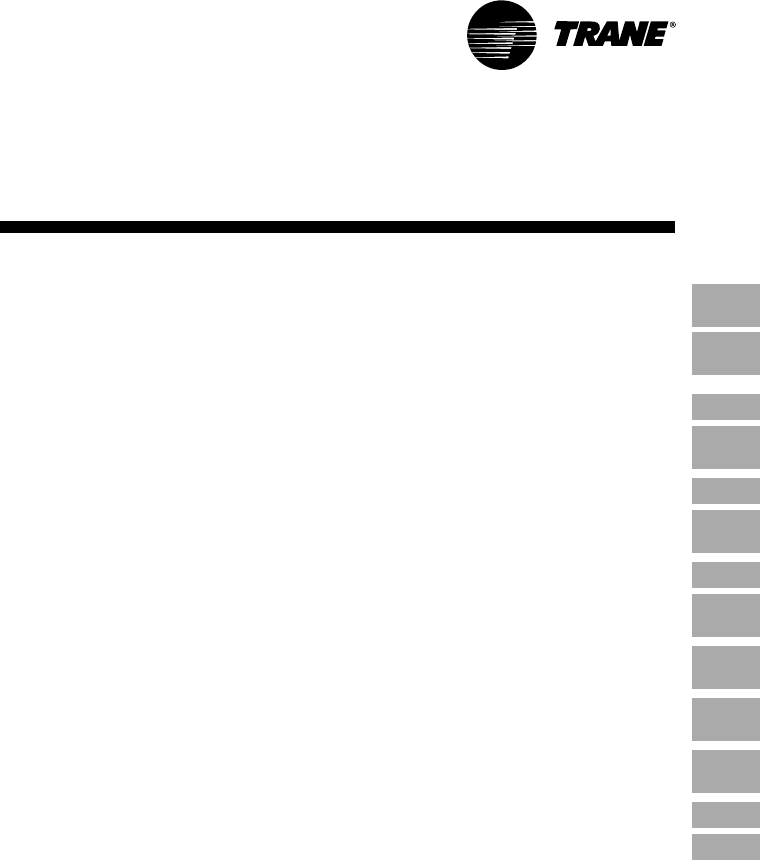
Digit 17 — Fan Discharge*
Horizontal Arrangement
1 = Arrangement 1, Top
2 = Arrangement 2, Side
3 = Arrangement 3, Bottom
*Select arrangements from page 6.
Vertical Arrangement
4 = Arrangement 4, Side
5 = Arrangement 5, Top
6 = Arrangement 6, Side
*Select arrangements from page 6.
Digit 18 — Inlet Hood and Birdscreen
0 = None
A = Inlet Hood and Birdscreen with
Permanent Filters
B = Inlet Hood and Birdscreen without
Filters
Digit 19 — V-Bank Filter Section
0 = No Selection
A = V-Bank Filter Section with Permanent
Filters
B = V-Bank Filter Section without Filters
Digit 20 — Dampers/Mixing Box
0 = No Selection
A = Motorized RA Damper
B = Motorized 75/25 Damper
C = Mixing Box — Temperature Control
D = Mixing Box — Building Pressure
Control
E = Mixing Box — Manual Control
Digit 21 — Miscellaneous Options
A = Controls Opposite from Standard
B = Motorized Inlet Damper
C = Motorized Outlet Damper
D = Insulation on Basic Frame
E = Insulation on Filter Section
F = Internal Blower/Motor Isolation
G = Extended Grease Lines
H = Inlet On-Off Duct Stat
K = 115V Duplex Service Receptacle with
Power Transformer
L = Circuit Analyzer
M = Painted Basic Unit and Accessories
N = UV Flame Sensor
P = Clogged Filter Switch with Light
Q = Exhaust Interlock
R = Interlocking Relay
T = City of Chicago Controls
V = Omit Disconnect Switch
W= High Gas Pressure Regulator 1-5 PSIG
X = High Gas Pressure Regulator 5-10 PSIG
Y = Adjustable Drive
S = Special
8 = Low Gas Pressure Burner
9MUA-PRC001-EN
Performance
Data
Table PD-1 — Direct-Fired Outdoor Unit
CFM FPM Total External Static Pressure (WC)
Models Blower STD Air Outlet ¼” 3/8” ½” ¾” 1” 1 ¼” 1 ½” 2”
DFO Size @ 70 Velocity HP
1600 1915 ¾11 1 ————
1800 2155 1 1 1 1 ½ 1 ½ 1 ½ — —
2000 2390 1 ½ 1 1½ 1 ½ 1 ½ 2 2 —
109 1-9” 2250 2690 1 ½ 1 ½ 1 ½ 22223
2500 2990 2 2 2 22333
2750 3290 2 2 2 33333
3000 3585 3 3 3 33355
3250 2180 1 ½ 2 2 23333
3500 2360 2 2 2 33335
112 1-12” 3750 2540 2 2 3 33335
4000 2720 3 3 3 33355
4250 2900 3 3 3 33555
45002190 223 3335—
115 1-15” 5000 2430 3 3 3 33555
5500 2670 3 3 3 55555
60002910 555 55557 ½
65002215 355 55557 ½
7000 2390 5 5 5 5557 ½7 ½
118 1-18” 7500 2565 5 5 5 5 5 7 ½ 7 ½ 7 ½
8000 2740 5 5 5 7 ½ 7 ½ 7 ½ 7 ½ 7 ½
8500 2915 5 5 7 ½ 7 ½ 7 ½ 7 ½ 7 ½ 10
9000 2190 5 5 5 5 7 ½ — — —
9500 2310 5 5 5 5 7 ½ 7 ½ — —
10000 2430 5 5 5 7 ½ 7 ½ 7 ½ 7 ½ —
215 2-15” 10500 2550 5 5 7 ½ 7 ½ 7 ½ 7 ½ 7 ½ —
11000 2670 7 ½ 7 ½ 7 ½ 7 ½ 7 ½ 7 ½ 10 10
11500 2790 7 ½ 7 ½ 7 ½ 7 ½ 7 ½ 10 10 10
12000 2910 7 ½7 ½7 ½7 ½10101015
12500 2125 7 ½ 7 ½ 7 ½ 7 ½ 7 ½ — — —
13000 2215 7 ½ 7 ½ 7 ½ 7 ½ 10 10 — —
218 2-18” 14000 2390 7 ½ 7 ½ 7 ½ 10 10 10 15 —
15000 2565 7 ½ 10 10 10 10 15 15 15
16000 2740 101010 1015151515
17000 2915 101010 1515151520
18000 2140 7 ½1010 10151515—
19000 2260 10 10 10 10 15 15 15 —
20000 2380 10 10 10 15 15 15 15 20
21000 2500 101515 1515152020
220 2-20” 22000 2620 15 15 15 15 15 20 20 20
23000 2740 15 15 15 15 15 20 20 20
24000 2860 15 15 15 15 20 20 20 25
25000 2980 15 15 15 20 20 20 20 25
26000 3100 15 20 20 20 20 20 25 25
25000 2450 15 15 15 15 20 20 20 25
26000 2550 15 15 15 20 20 20 20 25
27000 2650 15 15 15 20 20 20 20 25
222 2-22” 28000 2750 15 20 20 20 20 25 25 30
29000 2850 20 20 20 20 25 25 25 30
30000 2950 20 20 20 20 25 25 25 30
31000 3050 20 20 20 25 25 25 30 30
30000 2235 15 15 15 15 20 20 — —
32000 2385 15 15 15 20 20 20 25 —
34000 2535 15 20 20 20 20 25 25 30
36000 2685 20 20 20 20 25 25 30 30
225 2-25” 38000 2835 20 20 20 25 25 30 30 40
40000 2985 20 25 25 25 30 30 30 40
42000 3135 25 25 25 30 30 40 40 40
44000 3285 25 30 30 30 40 40 40 40
46000 3430 30 30 30 40 40 40 40 50
44000 2365 20 20 20 25 25 30 — —
48000 2580 20 25 25 25 30 30 40 —
52000 2800 252530 3040404050
230 2-30” 56000 3020 30 30 30 40 40 40 40 50
60000 3240 40 40 40 40 40 50 50 50
64000 3440 40 40 40 50 50 50 50 60
Notes:
External Pressure Drop in inches of water. Add pressure drop of the optional accessories, if used, to the pressure drop of the
duct work.
Fresh Air Inlet Hood and Birdscreen .13” WC
Fresh Air Inlet Hood With Filters .25” WC
Motor Operated Inlet Damper .13” WC
Motor Operated Discharge Damper .13” WC
V-Bank Filter Section .25” WC
Mixing Box . 40” WC
MUA-PRC001-EN10
Performance
Data
Table PD-2 — Direct-Fired Outdoor Unit — Burner Selection (MBh Input)
CFM
Models Std Air 70 F 80 F 90 F 100 F 110 F 120 F
DFO 70 F Rise Rise Rise Rise Rise Rise
1600 131 150 169 188 207 225
1800 148 169 190 211 232 254
2000 164 188 211 235 258 282
109 2250 185 211 238 264 291 317
2500 205 235 264 293 323 352
2750 226 258 291 323 355 387
3000 247 282 317 352 387 423
3250 267 305 343 382 420 458
3500 288 329 370 411 452 493
3750 308 352 396 440 484 528
112 4000 329 376 423 470 517 563
4250 349 399 449 499 549 599
4500 370 423 475 528 581 634
5000 411 470 528 587 646 704
115 5500 452 517 581 646 710 775
6000 493 563 634 704 775 845
6500 534 610 687 763 839 916
7000 575 657 740 822 904 986
7500 616 704 792 880 968 1057
118 8000 657 751 845 939 1033 1127
8500 698 798 898 998 1098 1197
9000 740 845 951 1057 1162 1268
9500 781 892 1004 1115 1227 1338
10000 822 939 1057 1174 1291 1409
215 10500 863 986 1109 1233 1356 1479
11000 904 1033 1162 1291 1420 1550
11500 945 1080 1215 1350 1485 1620
12000 986 1127 1268 1409 1550 1690
12500 1027 1174 1321 1467 1614 1761
13000 1068 1221 1373 1526 1679 1831
14000 1150 1315 1479 1643 1808 1972
218 15000 1233 1409 1585 1761 1937 2113
16000 1315 1503 1690 1878 2066 2254
17000 1397 1597 1796 1996 2195 2395
18000 1479 1690 1902 2113 2324 2536
19000 1561 1784 2007 2230 2453 2677
20000 1643 1878 2113 2348 2583 2817
21000 1726 1972 2219 2465 2712 2958
220 22000 1808 2066 2324 2583 2841 3099
23000 1890 2160 2430 2700 2970 3240
24000 1972 2254 2536 2817 3099 3381
25000 2054 2348 2641 2935 3228 3522
26000 2137 2442 2747 3052 3357 3663
25000 2054 2348 2641 2935 3228 3522
26000 2137 2442 2747 3052 3357 3663
27000 2219 2536 2853 3170 3487 3803
28000 2301 2630 2958 3287 3616 3944
222 29000 2383 2723 3064 3404 3745 4085
30000 2465 2817 3170 3522 3874 4226
31000 2547 2911 3275 3639 4003 4367
30000 2465 2817 3170 3522 3874 4226
32000 2630 3005 3381 3757 4132 4508
34000 2794 3193 3592 3991 4390 4790
36000 2958 3381 3803 4226 4649 5071
38000 3123 3569 4015 4461 4907 5353
225 40000 3287 3757 4226 4696 5165 5635
42000 3451 3944 4437 4930 5423 5917
44000 3616 4132 4649 5165 5682 6198
46000 3780 4320 4860 5400 5940 6480
44000 3616 4132 4649 5165 5682 6198
48000 3944 4508 5071 5635 6198 6762
52000 4273 4883 5494 6104 6715 7325
230 56000 4602 5259 5917 6574 7231 —
60000 4930 5635 6339 7043 7748 —
64000 5259 6010 6762 7513 — —
Notes:
1. Determine the temperature rise required through the heater by subtracting winter design temperature from the desired
indoor temperature.
2. Select burner required:
BTUH = CFM x T x 1.08
.92
Formula includes 1.08 constant for heat content of air and .92 factor which is an average ratio of net and gross heating
values of common fuel gases. (92% sensible, 8% latent).
3. Contact Diversified Commercial Products Technical Support on temperature rise requirements greater than 120 F.
11MUA-PRC001-EN
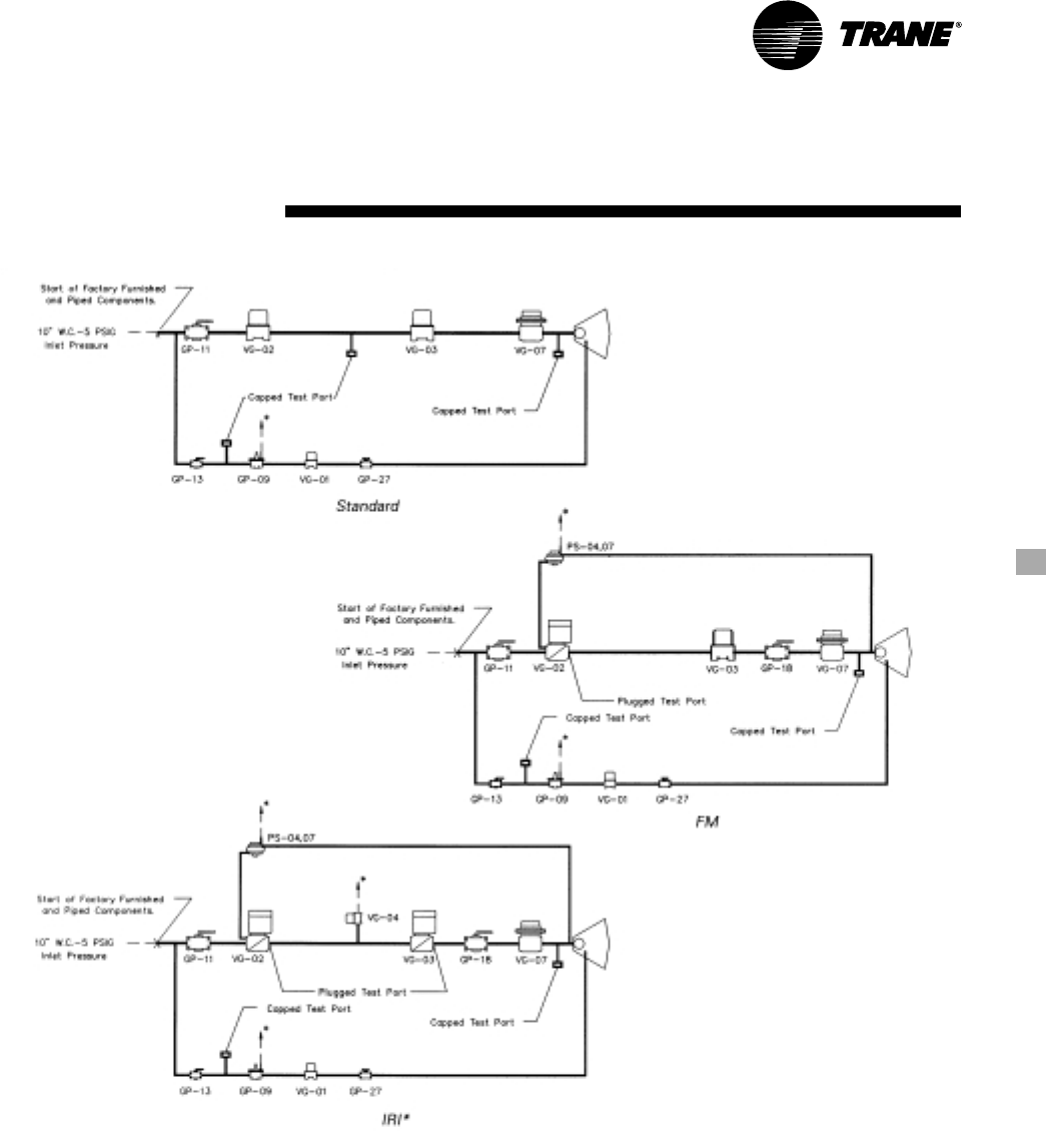
Gas
Piping
Component Identification
GP-09 Pilot Gas Pressure Regulator
GP-11 Main Gas Shutoff Valve
GP-13 Pilot Gas Shutoff Valve
GP-17 Auxiliary Gas Shutoff Valve
GP-18 Auxiliary Gas Shutoff Valve
GP-27 Orificed Needle Valve
VG-01 Pilot Gas Valve
VG-02 Main Gas Valve
VG-03 Auxiliary Gas Valve
VG-04 N/O Vent Valve
VG-07 Maxitrol Modulating Valve
PS-04 Low Gas Pressure Switch
PS-07 High Gas Pressure Switch
Notes:
1
Vents to outside furnished by factory
on outdoor units.
2
Under 825 MBh will require an additional
gas pressure regulator if inlet
pressure exceeds 1 psig.
3
4400 MBh and above will require a
minimum inlet pressure of 1 psig. For
inlet pressure under 1 psig, contact
factory.
4
For inlet pressure under 10” WC, contact
factory.
5
Contact factory for manifold required for
CGA.
*Items PS-04, PS-07, VG-04 and GP-18 are not required to
meet IRI requirements if the unit is ETL approved. Refer to
page 40.
MUA-PRC001-EN12
Table GP-1— Gas Pressure Regulator Selection
If Burner Size (BS) Is: And Gas Pressure (GP) Is: Then:
BS < 825 GP< 7” WC Call factory to verify availability and pricing
7”WC < GP < 10” WC Use low gas pressure burner
10”WC < GP < 1 PSI No low gas pressure burner or high gas pressure regulator required
1 PSI < GP < 5 PSI Use high gas pressure regulator 1-5 PSI
5 PSI < GP < 10 PSI Use high gas pressure regulator 5-10 PSI
10 PSI < GP < 50 PSI Use high gas pressure regulator over 10 PSI
50 PSI < GP Call factory to verify availability and pricing
990 < BS < 4125 GP < 7” WC Call factory to verify availability and pricing
7” WC < GP < 10” WC Use low gas pressure burner
10” WC < GP < 5 PSI No low gas pressure burner or high gas pressure regulator required
5 PSI < GP < 10 PSI Use high gas pressure regulator 5-10 PSI
10 PSI < GP < 50 PSI Use high gas pressure regulator over 10 PSI
50 PSI < GP Call factory to verify availability and pricing
4400 < BS < 7975 GP < 1 PSI Call factory to verify availability and pricing
1 PSI < GP < 5 PSI No low gas pressure burner or high gas pressure regulator required
5 PSI < GP < 10 PSI Use high gas pressure regulator 5-10 PSI
10 PSI < GP < 50 PSI Use high gas pressure regulator over 10 PSI
50 PSI < GP Call factory to verify availability and pricing
Gas
Piping

13MUA-PRC001-EN
Gas
Piping
Table GP-2 — Gas Pipe Connection Size — Direct-Fired Units — IRI Gas Train — R/A Meeting ETL
Inlet Gas Pressure (inches of water column)
MBH 6-7" 8-11" 12-14" 15-20" 21-27" 1 psi 2 psi 3 psi 4 psi 5 psi
275 1" ¾" ¾" ¾" ¾" ¾" ¾" ¾" ¾" ¾"
550 1 ¼" 1" ¾" ¾" ¾" ¾" ¾" ¾" ¾" ¾"
825 2" 1 ¼" 1 ¼" 1 ¼" 1 ¼" 1 ¼" 1 ¼" 1 ¼" 1 ¼" 1 ¼"
1,100 2" 1 ¼" 1 ¼" 1 ¼" 1 ¼“ 1 ¼” 1 ¼" 1 ¼" 1 ¼" 1 ¼"
1,375 2" 1 ½" 1 ¼" 1 ¼" 1 ¼" 1 ¼" 1 ¼" 1 ¼" 1 ¼" 1 ¼"
1,650 N/A 1 ½" 1 ¼" 1 ¼" 1 ¼" 1 ¼" 1 ¼" 1 ¼" 1 ¼" 1 ¼"
1,925 N/A 2" 1 ½" 1 ¼" 1 ¼" 1 ¼" 1 ¼" 1 ¼" 1 ¼" 1 ¼"
2,200 N/A 2" 1 ½" 1 ¼" 1 ¼" 1 ¼" 1 ¼" 1 ¼" 1 ¼" 1 ¼"
2,475 2 ½" 2" 2" 1 ½" 1 ¼" 1 ¼" 1 ¼" 1 ¼" 1 ¼" 1 ¼"
2,750 3" 2" 2" 1 ½" 1 ¼" 1 ¼" 1 ¼" 1 ¼" 1 ¼" 1 ¼"
3,025 3" 2 ½" 2" 2" 1 ½" 1 ¼" 1 ¼" 1 ¼" 1 ¼" 1 ¼"
3,300 N/A 2 ½" 2" 2" 2" 2" 2" 2" 2" 2"
3,575 N/A 2 ½" 2" 2" 2" 2" 2" 2" 2" 2"
3,850 N/A 2 ½" 2" 2" 2" 2" 2" 2" 2" 2"
4,125 N/A 2 ½" 2" 2" 2" 2" 2" 2" 2" 2"
4,400 N/A 2 ½" 2" 2" 2" 2" 2" 2" 2" 2"
4,675 N/A 3" 2 ½" 2" 2" 2" 2" 2" 2" 2"
4,950 N/A 3" 2 ½" 2" 2" 2" 2" 2" 2" 2"
5,225 N/A 3" 2 ½" 2" 2" 2" 2" 2" 2" 2"
5,500 N/A 3" 2 ½" 2 ½" 2" 2 ½" 2 ½" 2 ½" 2 ½" 2 ½"
5,775 N/A N/A 2 ½" 2 ½" 2 ½" 2 ½" 2 ½" 2 ½" 2 ½" 2 ½"
6,050 N/A N/A 2 ½" 2 ½" 2 ½" 2 ½" 2 ½" 2 ½" 2 ½" 2 ½"
6,325 N/A N/A 2 ½" 2 ½" 2 ½" 2 ½" 2 ½" 2 ½" 2 ½" 2 ½"
6,600 N/A N/A 2 ½" 2 ½" 2 ½" 2 ½" 2 ½" 2 ½" 2 ½" 2 ½"
6,875 N/A N/A 2 ½" 2 ½" 2 ½" 2 ½" 2 ½" 2 ½" 2 ½" 2 ½"
7,150 N/A N/A 3" 2 ½" 2 ½" 2 ½" 2 ½" 2 ½" 2 ½" 2 ½"
7,700 N/A N/A 3" 2 ½" 2 ½" 3" 3" 3" 3" 3"
8,250 N/A N/A 3" 3" 2 ½" 3" 3" 3" 3" 3"
8,800 N/A N/A N/A 3" 3" 3" 3" 3" 3" 3"
9,350 N/A N/A N/A 3" 3" 3" 3" 3" 3" 3"
9,900 N/A N/A N/A 3" 3" 3" 3" 3" 3" 3"
10,450 N/A N/A N/A N/A N/A N/A N/A N/A N/A N/A
11,000 N/A N/A N/A N/A N/A N/A N/A N/A N/A N/A
11,550 N/A N/A N/A N/A N/A N/A N/A N/A N/A N/A
Table GP-3 — Gas Pipe Connection Size — Direct-Fired Units — FM Gas Train — R/A Meeting ETL
Inlet Gas Pressure (inches of water column)
MBH 6-7" 8-11" 12-14" 15-20" 21-27" 1 psi 2 psi 3 psi 4 psi 5 psi
275 1" ¾" ¾" ¾" ¾" ¾" ¾" ¾" ¾" ¾"
550 1 ¼" 1" ¾" ¾" ¾" ¾" ¾" ¾" ¾" ¾"
825 1 ½" 1 ¼" 1 ¼" 1 ¼" 1 ¼" 1 ¼" 1 ¼" 1 ¼" 1 ¼" 1 ¼"
1,100 2" 1 ¼" 1 ¼" 1 ¼" 1 ¼" 1 ¼" 1 ¼" 1 ¼" 1 ¼" 1 ¼"
1,375 2" 1 ½" 1 ½" 1 ½" 1 ½" 1 ¼" 1 ¼" 1 ¼" 1 ¼" 1 ¼"
1,650 2" 1 ½" 1 ¼" 1¼" 1¼" 1 ¼" 1 ¼" 1 ¼" 1 ¼" 1 ¼"
1,925 2" 2" 1 ¼" 1¼" 1¼" 1 ¼" 1 ¼" 1 ¼" 1 ¼" 1 ¼"
2,200 N/A 2" 1 ½" 1¼" 1¼" 1 ¼" 1 ¼" 1 ¼" 1 ¼" 1 ¼"
2,475 N/A 2" 1 ½" 1¼" 1¼" 1 ¼" 1 ¼" 1 ¼" 1 ¼" 1 ¼"
2,750 N/A 2" 2" 1 ½" 1¼" 1 ¼" 1 ¼" 1 ¼" 1 ¼" 1 ¼"
3,025 N/A 2" 2" 1 ½" 1¼" 1 ¼" 1 ¼" 1 ¼" 1 ¼" 1 ¼"
3,300 N/A 2 ½" 2" 2" 2" 2" 2" 2" 2" 2"
3,575 N/A 3" 2" 2" 2" 2" 2" 2" 2" 2"
3,850 N/A 3" 2" 2" 2" 2" 2" 2" 2" 2"
4,125 N/A 3" 2" 2" 2" 2" 2" 2" 2" 2"
4,400 N/A 3" 2" 2" 2" 2" 2" 2" 2" 2"
4,675 N/A 3" 2" 2" 2" 2" 2" 2" 2" 2"
4,950 N/A 3" 2 ½" 2 ½" 2 ½" 2 ½" 2 ½" 2 ½" 2 ½" 2 ½"
5,225 N/A 3" 2 ½" 2 ½" 2 ½" 2 ½" 2 ½" 2 ½" 2 ½" 2 ½"
5,500 N/A 3" 2 ½" 2 ½" 2 ½" 2 ½" 2 ½" 2 ½" 2 ½" 2 ½"
5,775 N/A N/A 2 ½" 2 ½" 2 ½" 2 ½" 2 ½" 2 ½" 2 ½" 2 ½"
6,050 N/A N/A 2 ½" 2 ½" 2 ½" 2 ½" 2 ½" 2 ½" 2 ½" 2 ½"
6,325 N/A N/A 2 ½" 2 ½" 2 ½" 2 ½" 2 ½" 2 ½" 2 ½" 2 ½"
6,600 N/A N/A 2 ½" 2 ½" 2 ½" 2 ½" 2 ½" 2 ½" 2 ½" 2 ½"
6,875 N/A N/A 3" 2 ½" 2 ½" 2 ½" 2 ½" 2 ½" 2 ½" 2 ½"
7,150 N/A N/A 3" 2 ½" 2 ½" 2 ½" 2 ½" 2 ½" 2 ½" 2 ½"
7,700 N/A N/A 3" 3" 2 ½" 2 ½" 2 ½" 2 ½" 2 ½" 2 ½"
8,250 N/A N/A 3" 3" 3" 3" 3" 3" 3" 3"
8,800 N/A N/A N/A 3" 3" 3" 3" 3" 3" 3"
9,350 N/A N/A N/A 3" 3" 3" 3" 3" 3" 3"
9,900 N/A N/A N/A 3" 3" 3" 3" 3" 3" 3"
10,450 N/A N/A N/A N/A N/A N/A N/A N/A N/A N/A
11,000 N/A N/A N/A N/A N/A N/A N/A N/A N/A N/A
11,550 N/A N/A N/A N/A N/A N/A N/A N/A N/A N/A

MUA-PRC001-EN14
Gas
Piping
Table GP-4 — Gas Pipe Connection Size — Direct-Fired Units — Standard Gas Train — R/A Meeting ETL
Inlet Gas Pressure (inches of water column)
MBH 6-7" 8-11" 12-14" 15-20" 21-27" 1 psi 2 psi 3 psi 4 psi 5 psi
275 1" ¾" ¾" ¾" ¾" ¾" ¾" ¾" ¾" ¾"
550 1 ¼" 1" ¾" ¾" ¾" ¾" ¾" ¾" ¾" ¾"
825 1 ½" 1 ¼" 1 ¼" 1 ¼" 1 ¼" 1 ¼" 1 ¼" 1 ¼" 1 ¼" 1 ¼"
1,100 2" 1 ¼" 1 ¼" 1 ¼" 1 ¼" 1 ¼" 1 ¼" 1 ¼" 1 ¼" 1 ¼"
1,375 2" 1 ½" 1 ¼" 1 ¼" 1 ¼" 1 ¼" 1 ¼" 1 ¼" 1 ¼" 1 ¼"
1,650 2" 1 ½" 1 ¼" 1 ¼" 1 ¼" 1 ¼" 1 ¼" 1 ¼" 1 ¼" 1 ¼"
1,925 2 ½" 2" 1 ¼" 1 ¼" 1 ¼" 1 ¼" 1 ¼" 1 ¼" 1 ¼" 1 ¼"
2,200 2 ½" 2" 1 ½" 1 ¼" 1 ¼" 1 ¼" 1 ¼" 1 ¼" 1 ¼" 1 ¼"
2,475 2 ½" 2" 1 ½" 1 ¼" 1 ¼" 1 ¼" 1 ¼" 1 ¼" 1 ¼" 1 ¼"
2,750 2 ½" 2" 2" 1 ½" 1 ¼" 1 ¼" 1 ¼" 1 ¼" 1 ¼" 1 ¼"
3,025 2 ½" 2" 2" 1 ½" 1 ¼" 1 ¼" 1 ¼" 1 ¼" 1 ¼" 1 ¼"
3,300 2 ½" 2" 2" 2" 2" 2" 2" 2" 2" 2"
3,575 3" 2 ½" 2" 2" 2" 2" 2" 2" 2" 2"
3,850 3" 2 ½" 2" 2" 2" 2" 2" 2" 2" 2"
4,125 N/A 2 ½" 2" 2" 2" 2" 2" 2" 2" 2"
4,400 N/A 2 ½" 2" 2" 2" 2" 2" 2" 2" 2"
4,675 N/A 2 ½" 2" 2" 2" 2" 2" 2" 2" 2"
4,950 N/A 2 ½" 2" 2" 2" 2" 2" 2" 2" 2"
5,225 N/A 2 ½" 2 ½" 2" 2" 2" 2" 2" 2" 2"
5,500 N/A 2 ½" 2 ½" 2" 2" 2" 2" 2" 2" 2"
5,775 N/A 2 ½" 2 ½" 2 ½" 2 ½" 2 ½" 2 ½" 2 ½" 2 ½" 2 ½"
6,050 N/A 3 2 ½" 2 ½" 2 ½" 2 ½" 2 ½" 2 ½" 2 ½" 2 ½"
6,325 N/A 3 2 ½" 2 ½" 2 ½" 2 ½" 2 ½" 2 ½" 2 ½" 2 ½"
6,600 N/A 3 2 ½" 2 ½" 2 ½" 2 ½" 2 ½" 2 ½" 2 ½" 2 ½"
6,875 N/A 3 2 ½" 2 ½" 2 ½" 2 ½" 2 ½" 2 ½" 2 ½" 2 ½"
7,150 N/A N/A 2 ½" 2 ½" 2 ½" 2 ½" 2 ½" 2 ½" 2 ½" 2 ½"
7,700 N/A N/A 2 ½" 2 ½" 2 ½" 2 ½" 2 ½" 2 ½" 2 ½" 2 ½"
8,250 N/A N/A 2 ½" 2 ½" 2 ½" 2 ½" 2 ½" 2 ½" 2 ½" 2 ½"
8,800 N/A N/A 3 3 3 3 3 3 3 3
9,350 N/A N/A 3 3 3 3 3 3 3 3
9,900 N/A N/A 3 3 3 3 3 3 3 3
10,450 N/A N/A N/A N/A N/A N/A N/A N/A N/A N/A
11,000 N/A N/A N/A N/A N/A N/A N/A N/A N/A N/A
11,550 N/A N/A N/A N/A N/A N/A N/A N/A N/A N/A
Table GP-5 — Gas Pipe Connection Size — Direct-Fired Units — IRI Gas Train — 100% OA or R/A Not ETL
Inlet Gas Pressure (inches of water column)
MBH 6-7" 8-11" 12-14" 15-20" 21-27" 1 psi 2 psi 3 psi 4 psi 5 psi
275 1 ¼" ¾" ¾" ¾" ¾" ¾" ¾" ¾" ¾" ¾"
550 N/A 1" ¾" ¾" ¾" ¾" ¾" ¾" ¾" ¾"
825 N/A N/A 1" ¾" ¾" ¾" ¾" ¾" ¾" ¾"
1,100 N/A 1 ½" 1 ¼" 1 ¼" 1 ¼" 1 ¼" 1 ¼" 1 ¼" 1 ¼" 1 ¼"
1,375 N/A 2" 1 ¼" 1 ¼" 1 ¼" 1 ¼" 1 ¼" 1 ¼" 1 ¼" 1 ¼"
1,650 N/A N/A 1 ½" 1 ¼" 1 ¼" 1 ¼" 1 ¼" 1 ¼" 1 ¼" 1 ¼"
1,925 N/A N/A 2" 1 ½" 1 ¼" 1 ¼" 1 ¼" 1 ¼" 1 ¼" 1 ¼"
2,200 N/A N/A 2" 1 ½" 1 ¼" 1 ¼" 1 ¼" 1 ¼" 1 ¼" 1 ¼"
2,475 N/A N/A 2" 2" 1 ½" 1 ¼" 1 ¼" 1 ¼" 1 ¼" 1 ¼"
2,750 N/A N/A 2" 2" 1 ½" 1 ¼" 1 ¼" 1 ¼" 1 ¼" 1 ¼"
3,025 N/A N/A 2" 2" 2" 2" 2" 2" 2" 2"
3,300 N/A N/A 2" 2" 2" 2" 2" 2" 2" 2"
3,575 N/A N/A 2 ½" 2" 2" 2" 2" 2" 2" 2"
3,850 N/A N/A 2 ½" 2" 2" 2" 2" 2" 2" 2"
4,125 N/A N/A 2 ½" 2" 2" 2" 2" 2" 2" 2"
4,400 N/A N/A 2 ½" 2 ½" 2" 2" 2" 2" 2" 2"
4,675 N/A N/A 2 ½" 2 ½" 2" 2" 2" 2" 2" 2"
4,950 N/A N/A 2 ½" 2 ½" 2" 2" 2" 2" 2" 2"
5,225 N/A N/A 3" 2 ½" 2" 2" 2" 2" 2" 2"
5,500 N/A N/A 3" 2 ½" 2 ½" 2" 2" 2" 2" 2"
5,775 N/A N/A 3" 2 ½" 2 ½" 2" 2" 2" 2" 2"
6,050 N/A N/A 3" 2 ½" 2 ½" 2 ½" 2 ½" 2 ½" 2 ½" 2 ½"
6,325 N/A N/A N/A 2 ½" 2 ½" 2 ½" 2 ½" 2 ½" 2 ½" 2 ½"
6,600 N/A N/A N/A 3" 2 ½" 2 ½" 2 ½" 2 ½" 2 ½" 2 ½"
6,875 N/A N/A N/A 3" 2 ½" 2 ½" 2 ½" 2 ½" 2 ½" 2 ½"
7,150 N/A N/A N/A 3" 2 ½" 2 ½" 2 ½" 2 ½" 2 ½" 2 ½"
7,700 N/A N/A N/A 3" 2 ½" 2 ½" 2 ½" 2 ½" 2 ½" 2 ½"
8,250 N/A N/A N/A N/A 2 ½" 2 ½" 2 ½" 2 ½" 2 ½" 2 ½"
8,800 N/A N/A N/A N/A 3" 2 ½" 2 ½" 2 ½" 2 ½" 2 ½"
9,350 N/A N/A N/A N/A 3" 3" 3" 3" 3" 3"
9,900 N/A N/A N/A N/A 3" 3" 3" 3" 3" 3"
10,450 N/A N/A N/A N/A N/A N/A N/A N/A N/A N/A
11,000 N/A N/A N/A N/A N/A N/A N/A N/A N/A N/A
11,550 N/A N/A N/A N/A N/A N/A N/A N/A N/A N/A
12,100 N/A N/A N/A N/A N/A N/A N/A N/A N/A N/A

15MUA-PRC001-EN
Table GP-7 — Gas Pipe Connection Size— Direct-Fired Units — Standard Gas Train — 100% OA or R/A Not ETL
Inlet Gas Pressure (inches of water column)
MBH 6-7" 8-11" 12-14" 15-20" 21-27" 1 psi 2 psi 3 psi 4 psi 5 psi
275 1 ¼" ¾" ¾" ¾" ¾" ¾" ¾" ¾" ¾" ¾"
550 1 ¼" 1" ¾" ¾" ¾" ¾" ¾" ¾" ¾" ¾"
825 N/A N/A 1" 1" ¾" ¾" ¾" ¾" ¾" ¾"
1,100 N/A 2" 1 ¼" 1 ¼" 1 ¼" 1 ¼" 1 ¼" 1 ¼" 1 ¼" 1 ¼"
1,375 N/A 2" 1 ¼" 1 ¼" 1 ¼" 1 ¼" 1 ¼" 1 ¼" 1 ¼" 1 ¼"
1,650 N/A 2" 1 ¼" 1 ¼" 1 ¼" 1 ¼" 1 ¼" 1 ¼" 1 ¼" 1 ¼"
1,925 N/A N/A 1 ½" 1 ¼" 1 ¼" 1 ¼" 1 ¼" 1 ¼" 1 ¼" 1 ¼"
2,200 N/A 2 ½" 2" 1 ½" 1 ¼" 1 ¼" 1 ¼" 1 ¼" 1 ¼" 1 ¼"
2,475 N/A 2 ½" 2" 1 ½" 1 ¼" 1 ¼" 1 ¼" 1 ¼" 1 ¼" 1 ¼"
2,750 N/A 2 ½" 2" 1 ½" 1 ¼" 1 ¼" 1 ¼" 1 ¼" 1 ¼" 1 ¼"
3,025 N/A 2 ½" 2" 2" 2" 2" 2" 2" 2" 2"
3,300 N/A 3" 2" 2" 2" 2" 2" 2" 2" 2"
3,575 N/A 3" 2" 2" 2" 2" 2" 2" 2" 2"
3,850 N/A N/A 2" 2" 2" 2" 2" 2" 2" 2"
4,125 N/A N/A 2 ½" 2" 2" 2" 2" 2" 2" 2"
4,400 N/A N/A 2 ½" 2" 2" 2" 2" 2" 2" 2"
4,675 N/A N/A 2 ½" 2" 2" 2" 2" 2" 2" 2"
4,950 N/A N/A 2 ½" 2 ½" 2" 2" 2" 2" 2" 2"
5,225 N/A N/A 2 ½" 2 ½" 2" 2" 2" 2" 2" 2"
5,500 N/A N/A 2 ½" 2 ½" 2" 2" 2" 2" 2" 2"
5,775 N/A N/A 2 ½" 2 ½" 2" 2" 2" 2" 2" 2"
6,050 N/A N/A 2 ½" 2 ½" 2 ½" 2 ½" 2 ½" 2 ½" 2 ½" 2 ½"
6,325 N/A N/A 2 ½" 2 ½" 2 ½" 2 ½" 2 ½" 2 ½" 2 ½" 2 ½"
6,600 N/A N/A 2 ½" 2 ½" 2 ½" 2 ½" 2 ½" 2 ½" 2 ½" 2 ½"
6,875 N/A N/A 3" 2 ½" 2 ½" 2 ½" 2 ½" 2 ½" 2 ½" 2 ½"
7,150 N/A N/A 3" 2 ½" 2 ½" 2 ½" 2 ½" 2 ½" 2 ½" 2 ½"
7,700 N/A N/A 3" 2 ½" 2 ½" 2 ½" 2 ½" 2 ½" 2 ½" 2 ½"
8,250 N/A N/A N/A 3" 2 ½" 2 ½" 2 ½" 2 ½" 2 ½" 2 ½"
8,800 N/A N/A N/A 3" 2 ½" 2 ½" 2 ½" 2 ½" 2 ½" 2 ½"
9,350 N/A N/A N/A 3" 3" 3" 3" 3" 3" 3"
9,900 N/A N/A N/A N/A 3" 3" 3" 3" 3" 3"
10,450 N/A N/A N/A N/A 3" 3" 3" 3" 3" 3"
11,000 N/A N/A N/A N/A 3" 3" 3" 3" 3" 3"
11,550 N/A N/A N/A N/A N/A CF CF CF CF CF
12,100 N/A N/A N/A N/A N/A CF CF CF CF CF
Note:
CF=Contact Factory
Gas
Piping
Table GP-6 — Gas Pipe Connection Size— Direct-Fired Units — FM Gas Train — 100% OA or R/A Not ETL
Inlet Gas Pressure (inches of water column)
MBH 6-7" 8-11" 12-14" 15-20" 21-27" 1 psi 2 psi 3 psi 4 psi 5 psi
275 1 ¼" ¾" ¾" ¾" ¾" ¾" ¾" ¾" ¾" ¾"
550 N/A 1" ¾" ¾" ¾" ¾" ¾" ¾" ¾" ¾"
825 N/A 1 ¼" 1" 1" ¾" ¾" ¾" ¾" ¾" ¾"
1,100 N/A 2" 1 ¼" 1 ¼" 1 ¼" 1 ¼" 1 ¼" 1 ¼" 1 ¼" 1 ¼"
1,375 N/A 2" 1 ¼" 1 ¼" 1 ¼" 1 ¼" 1 ¼" 1 ¼" 1 ¼" 1 ¼"
1,650 N/A 2" 1 ¼" 1 ¼" 1 ¼" 1 ¼" 1 ¼" 1 ¼" 1 ¼" 1 ¼"
1,925 N/A 2" 1 ½" 1 ¼" 1 ¼" 1 ¼" 1 ¼" 1 ¼" 1 ¼" 1 ¼"
2,200 N/A N/A 2" 1 ½" 1 ¼" 1 ¼" 1 ¼" 1 ¼" 1 ¼" 1 ¼"
2,475 N/A N/A 2" 1 ½" 1 ¼" 1 ¼" 1 ¼" 1 ¼" 1 ¼" 1 ¼"
2,750 N/A N/A 2" 2" 2" 1 ½" 1 ½" 1 ½" 1 ½" 1 ½"
3,025 N/A N/A 2" 2" 2" 2" 2" 2" 2" 2"
3,300 N/A N/A 2" 2" 2" 2" 2" 2" 2" 2"
3,575 N/A N/A 2" 2" 2" 2" 2" 2" 2" 2"
3,850 N/A N/A 2" 2" 2" 2" 2" 2" 2" 2"
4,125 N/A N/A 2 ½" 2" 2" 2" 2" 2" 2" 2"
4,400 N/A N/A 3" 2" 2" 2" 2" 2" 2" 2"
4,675 N/A N/A 3" 2 ½" 2" 2" 2" 2" 2" 2"
4,950 N/A N/A 3" 2 ½" 2" 2" 2" 2" 2" 2"
5,225 N/A N/A 3" 2 ½" 2 ½" 2 ½" 2 ½" 2 ½" 2 ½" 2 ½"
5,500 N/A N/A 3" 2 ½" 2 ½" 2 ½" 2 ½" 2 ½" 2 ½" 2 ½"
5,775 N/A N/A 3" 2 ½" 2 ½" 2 ½" 2 ½" 2 ½" 2 ½" 2 ½"
6,050 N/A N/A 3" 2 ½" 2 ½" 2 ½" 2 ½" 2 ½" 2 ½" 2 ½"
6,325 N/A N/A N/A 2 ½" 2 ½" 2 ½" 2 ½" 2 ½" 2 ½" 2 ½"
6,600 N/A N/A N/A 3" 2 ½" 2 ½" 2 ½" 2 ½" 2 ½" 2 ½"
6,875 N/A N/A N/A 3" 2 ½" 2 ½" 2 ½" 2 ½" 2 ½" 2 ½"
7,150 N/A N/A N/A 3" 2 ½" 2 ½" 2 ½" 2 ½" 2 ½" 2 ½"
7,700 N/A N/A N/A 3" 2 ½" 2 ½" 2 ½" 2 ½" 2 ½" 2 ½"
8,250 N/A N/A N/A N/A 2 ½" 2 ½" 2 ½" 2 ½" 2 ½" 2 ½"
8,800 N/A N/A N/A N/A 3" 2 ½" 2 ½" 2 ½" 2 ½" 2 ½"
9,350 N/A N/A N/A N/A 3" 3" 3" 3" 3" 3"
9,900 N/A N/A N/A N/A 3" 3" 3" 3" 3" 3"
10,450 N/A N/A N/A N/A 3" 3" 3" 3" 3" 3"
11,000 N/A N/A N/A N/A N/A 3" 3" 3" 3" 3"
11,550 N/A N/A N/A N/A N/A CF CF CF CF CF
12,100 N/A N/A N/A N/A N/A CF CF CF CF CF
Note:
CF = Contact Factory
MUA-PRC001-EN16
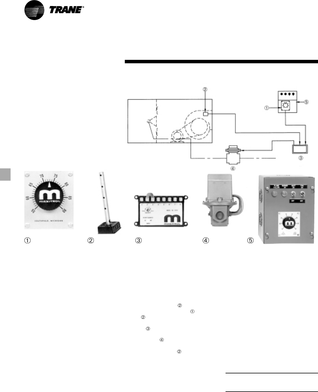
Controls
Component Description
1
Remote Temperature Selector
Not temperature sensitive. Mounted on
remote control station.
2
Air Sensor
Installed in blower discharge.
3
Amplifier
Installed in electrical control panel.
Contains wiring terminals, sensitivity
adjustments and one calibrating
potentiometer.
4
Modulator/Regulator Valve
Mounted in gas piping manifold.
Receives electrical signal from amplifier
and adjusts gas pressure to maintain
desired temperature.
5
Remote Control Station
Optional
System 14 — Constant Discharge Air Temperatures
System 14 Applications
Controls discharge air temperature with
instantaneous response and is ideal for
industrial areas and commercial spaces
such as kitchens, hotels, restaurants and
boiler rooms.
Control Operation
Desired temperature at is set at the
remote temperature selector . The air
sensor senses leaving air temperature
and sends an electrical signal to the
amplifier . The amplifier then sends an
electrical signal to the modulator/
regulator valve , which adjusts gas
pressure to the burner, maintaining the
desired temperature at .
Control Sequence with Fan and
Heat Switches
Fan and heat switches are included
when a remote control station is ordered
as an option.
Fan Switch On
Optional damper opens, damper end
switch closes, fan motor starter is
energized, fan runs.
The freeze-stat will stop the fan if the
discharge leaving air temperature is
below 45 F, three minutes after the fan is
turned on.
Fan Switch Off
Optional damper closes, damper end
switch opens, fan motor starter is de-
energized, fan is off.
Heat Switch On
If the fan switch is on, and the air flow
switch closes, power is applied to the
flame failure safeguard relay to begin
predetermined ignition sequence.
Note: The fan switch must be on, or the
burner will not light, even if the heat
switch is on.
Heat Switch Off
Heat is off.
Optional
17MUA-PRC001-EN
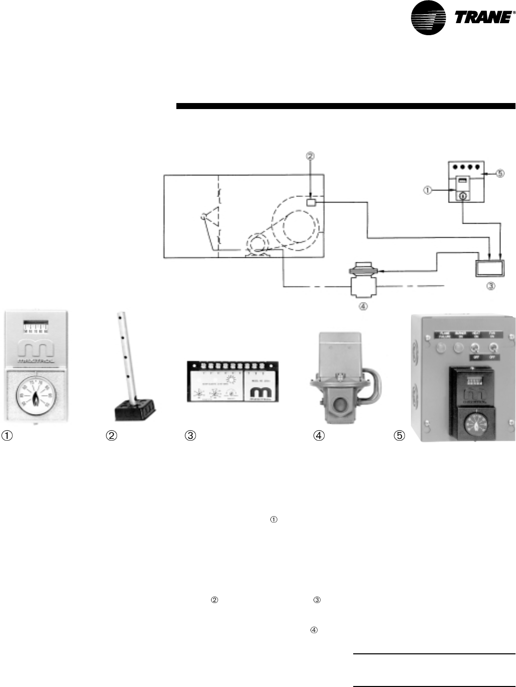
Controls
Component Description
1
Selectrastat™
Mounted on remote control station in
heated area where temperature is
sensed. Temperature range 55 F to 90 F.
2
Air Monitor
Installed in blower discharge. Senses
temperature.
3
Amplifier
Installed in electrical control panel.
Contains adjustments for maximum and
minimum discharge air temperature,
three calibrating potentiometers and a
sensitivity adjustment.
4
Modulator/Regulator Valve
Mounts in gas piping manifold. Receives
electrical signal from amplifier and
adjusts gas pressure to maintain desired
temperature.
5
Remote Control Station
Optional
System 44 Applications
Provides space temperature control
electronically and is ideal for commercial
and industrial buildings.
Temperature Control Operation
Desired temperature at is set at the
Selectrastat on the remote control
station. The Selectrastat controls the
discharge air temperature as long as this
temperature remains within preset
maximum and minimum limits. If the
discharge air temperature approaches
either of the set limits, the discharge air
monitor will signal the amplifier ,
which will adjust the discharge air
temperature to a higher or lower level
via the modulator/regulator valve .
When the space temperature
approaches the assigned setting, the
Selectrastat resumes control.
Control Sequence with Fan and
Heat Switches
Fan and heat switches are included
when the remote control station is
ordered as an option.
Fan Switch On
Optional damper opens, damper end
switch closes, fan motor starter is
energized, fan runs.
The freeze-stat will stop the fan if the
discharge leaving air temperature is
below 45 F, three minutes after the fan is
turned on.
Fan Switch Off
Optional damper closes, damper end
switch opens, fan motor starter is de-
energized, fan is off.
Heat Switch On
If the fan switch is on, and the air flow
switch closes, power is applied to the
flame failure safeguard relay to begin
predetermined ignition sequence.
Note: The fan switch must be on, or the
burner will not light, even if the heat
switch is on.
Heat Switch Off
Heat is off.
Optional
System 44 — Space Temperature Control
MUA-PRC001-EN18
Table EP-2— Motor Electrical Data — Two-Speed Motor
2-Speed/1-Winding 2-Speed/2-Winding
1800/900 RPM 1800/1200 RPM
3-Phase 3-Phase
HP 208 230 460 208 230 460
¾ NANANANANANA
1 3.5/1.5 3.4/1.6 1.8/.75 3.2/1.8 3.4/2.2 1.7/1.1
1 ½ 5.0/2.1 4.8/2.1 2.25/.95 5.0/2.9 4.9/2.8 2.4/1.4
2 6.2/2.6 6.4/2.7 3.0/1.3 6.1/3.5 5.9/3.8 3.4/2.1
3 9.1/3.3 8.3/3.3 4.9/1.9 9.0/4.8 8.4/4.8 4.6/2.6
5 14.7/5.2 13.4/5.1 7.0/2.7 16.9/9.7 15.5/10.2 7.1/4.8
7 ½ 24.0/10.0 24.5/11.0 10.5/4.2 22.0/12.3 19.5/12.3 10.0/6.0
10 29.5/11.3 30.0/12.4 13.0/5.5 30.0/17.0 28.0/17.5 13.5/7.5
15 43.0/15.2 40.0/14.0 19.4/7.2 47.0/22.0 54.0/21.0 19.0/11.0
20 56.0/20.0 54.0/21.0 26.0/10.0 56.0/29.0 51.0/27.0 24.0/12.0
25 NA NA 31.0/10.0 NA NA 30.0/17.0
30 NA NA 36.6/12.4 NA NA 38.0/18.0
40 NA NA 50.0/16.5 NA NA 48.0/24.0
50 NA NA 59.0/21.0 NA NA 59.0/30.0
60 NA NA NA NA NA NA
Notes:
NA = Not Available
FLA based on NEC ratings
Table EP-1 — Motor Electrical Data — Single-Speed Motor
Energy-Effic. ODP TEFC Energy-Effic. TEFC
ODP — 1800 RPM 1800 RPM 1800 RPM 1800 RPM
Single Phase 3-Phase 3-Phase 3-Phase 3-Phase
HP 115 208 230 208 230 460 208 230 460 208 230 460 208 230 460
¾ 11.0 5.4 5.5 2.5 2.6 1.3 NA NA NA 3.2 3.0 1.5 NA NA NA
1 12.6 6.2 6.3 3.5 2.8 1.4 3.1 2.7 1.4 3.6 2.8 1.4 3.1 2.7 1.35
1 ½ 20.0 10.5 10.0 5.0 4.2 2.1 4.5 3.9 2.0 5.0 4.2 2.1 4.5 3.9 1.95
2 21.0 12.6 10.5 6.3 5.6 2.8 6.0 5.2 2.6 6.5 5.6 2.8 6.1 5.3 2.65
3 32.0 16.8 16.0 9.5 8.0 4.0 8.7 7.8 3.9 8.5 8.2 4.1 8.8 7.6 3.8
5 NA 25.0 23.0 15.4 13.2 6.6 13.8 12.0 6.0 15.0 13.4 6.7 14.2 12.4 6.2
7 ½ NA 33.0 31.0 22.0 20.0 10.0 22.5 19.6 9.8 21.5 19.2 9.6 21.4 18.6 9.3
10 NA NA 42.0 26.4 25.2 12.6 28.0 24.4 12.2 28.0 25.2 12.6 29.0 25.0 12.5
15 NA NA NA 42.0 40.6 20.3 42.1 36.6 18.3 NA 38.8 19.4 41.2 36.6 18.3
20 NA NA NA 53.0 50.0 25.0 55.2 48.0 24.0 NA 48.0 24.0 53.8 49.0 24.5
25 NA NA NA 72.0 59.0 29.5 67.3 57.0 28.5 NA 60.0 30.0 63.5 57.0 28.5
30 NA NA NA 78.0 71.0 35.5 81.0 69.0 34.5 NA 76.0 38.0 79.8 69.0 34.5
40 NA NA NA 108.0 95.6 47.8 NA 92.0 46.0 NA 94.0 47.0 NA 92.0 46.0
50 NA NA NA 140.0 120.0 60.0 NA 116.0 58.0 NA 120.0 60.0 NA 116.0 58.0
60 NA NA NA NA 145.0 72.5 NA 144.0 72.0 NA 140.0 70.0 NA 142.0 71.0
Notes:
NA = Not Available
FLA based on NEC ratings
Electric
Power
19MUA-PRC001-EN
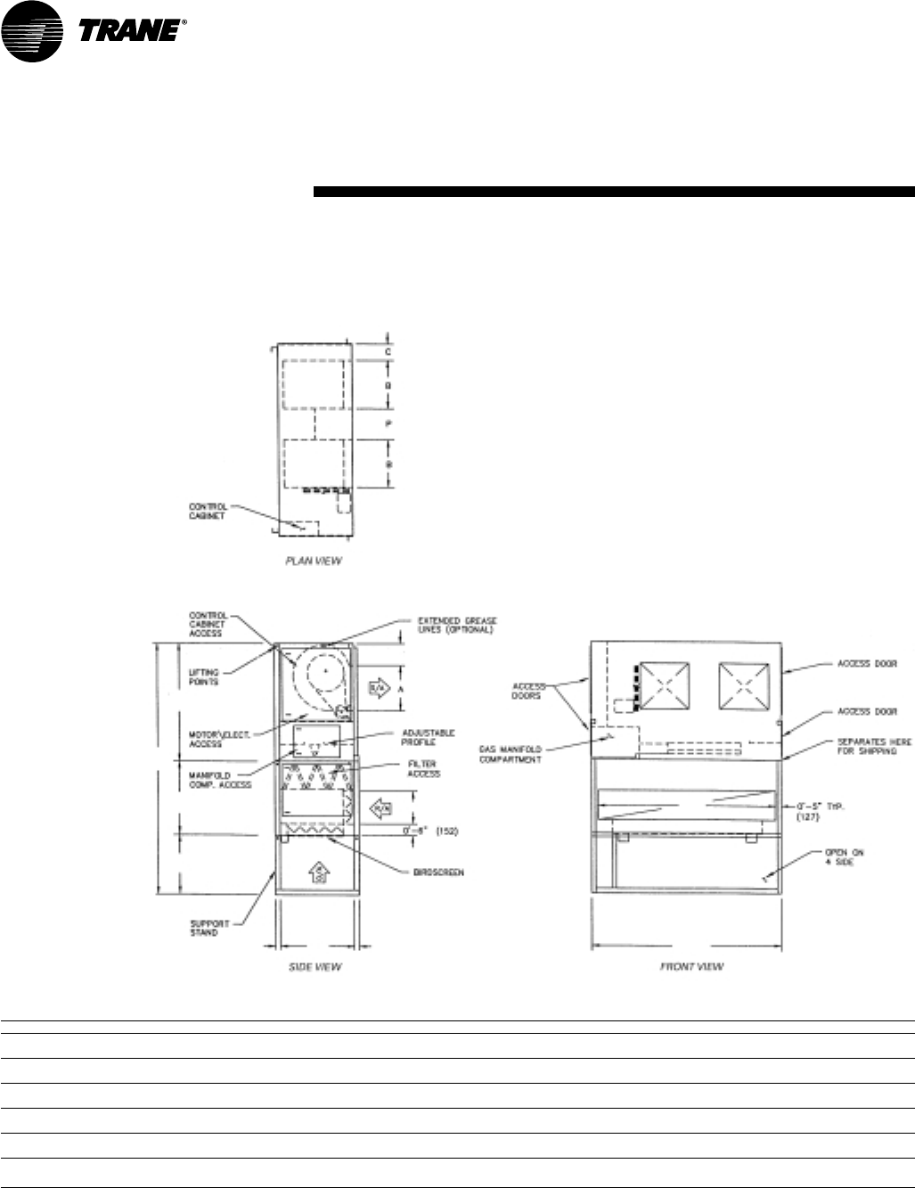
Dimension and
Weights
Inlet Hood Support (By Others)
• The purpose of hood support is to
support the weight of the unit
accessories which are attached to the
inlet of the basic unit.
• The hood support can be made from
two, 2” x 2” x ¼” angle iron.
• One angle iron support should be
located in, or close to, the outer
corners of the hood. The supports can
be bolted to the hood.
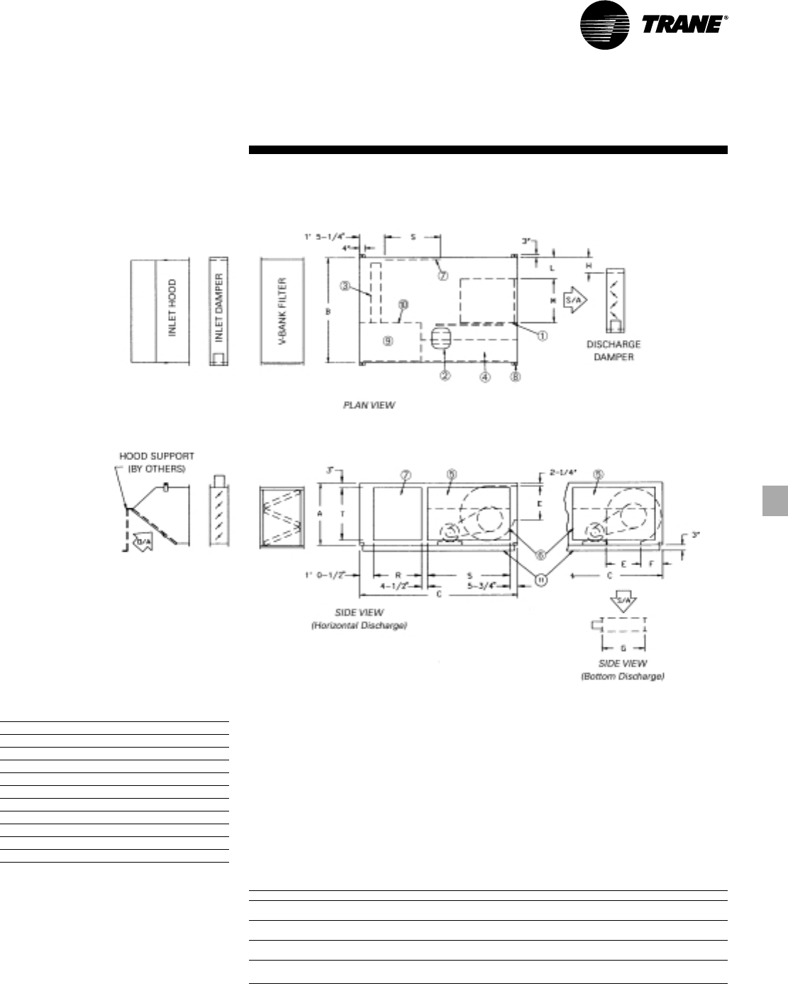
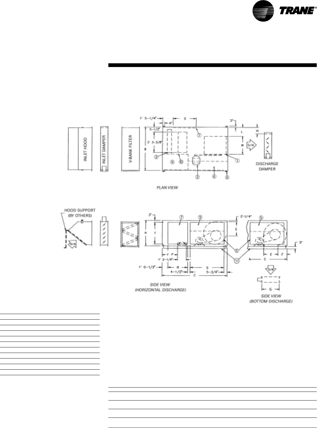
Table DW-1
Model A B C E F G H L M R S T
109 3' 0" 4' 4" 6' 5" 10-3/8" 1' 3-1/8" 1' 2-7/16"11-
11/16" 1' 2-½" 11-15/16" 1' 9" 2' 9" 2' 5"
(914) (1321) (1956) (264) (384) (367) (297) (368) (303) (533) (838) (737)
112 3' 0" 4' 4" 6' 5" 1' 1-9/16"1' 1-9/16"1' 2-7/16"11-
11/16" 1' 0-5/8"1' 3-15/16" 1' 9" 2' 9" 2' 5"
(914) (1321) (1956) (344) (344) (367) (297) (321) (405) (533) (838) (737)
115 3' 0" 4' 4" 6' 5" 1' 4" 1' 0-3/8" 1' 7-7/8"6-
15/16"11-
1/8" 1' 6-15/16" 1' 9" 2' 9" 2' 5"
(914) (1321) (1956) (406) (314) (505) (176) (283) (481) (533) (838) (737)
118 3' 0" 4' 4" 6' 5" 1' 7" 1' 0-3/8" 1' 7-7/8"6-
15/16"7-
7/8" 1' 10-1/16" 1' 9" 2' 9" 2' 5"
(914) (1321) (1956) (483) (314) (505) (176) (200) (560) (533) (838) (737)
Notes:
1. To permit blower shaft replacement, the side opposite the controls should have clearance equal to the unit width.
2. Minimum of 3’ for serviceability clearance.
• The bottom of the angle iron support
should be fitted with a base. The base
can sit on the roof and does not have
to be fixed to the roof. An isolation pad
may be put between the base and the
roof.
Horizontal Arrangement — Single Blower
109 112 115 118
Item Unit Components
1 Centrifugal Supply Fan
2 Fan Motor
3 Heat Source (Line Burner)
4 Control Cabinet
5 Hinged Control Cabinet Access Door
6 Motor and Drive Access Plate
7 Access Door
8 Removable Suspension Lifting Lug
9 Manifold Compartment
10 Observation Port
11 Unit Base

MUA-PRC001-EN20
Dimension and
Weights
Inlet Hood Support (By Others)
• The purpose of hood support is to
support the weight of the unit
accessories which are attached to the
inlet of the basic unit.
• The hood support can be made from
two, 2” x 2” x ¼” angle iron.
• One angle iron support should be
located in, or close to, the outer
corners of the hood. The supports can
be bolted to the hood.
Item Unit Components
1 Centrifugal Supply Fan
2 Fan Motor
3 Heat Source (Line Burner)
4 Control Cabinet
5 Hinged Control Cabinet Access Door
6 Motor and Drive Access Plate
7 Access Door
8 Removable Suspension Lifting Lug
9 Manifold Compartment
10 Observation Port
11 Unit Base
• The bottom of the angle iron support
should be fitted with a base. The base
can sit on the roof and does not have
to be fixed to the roof. An isolation pad
may be put between the base and the
roof.
Horizontal Arrangement — Double Blower
215 218 220 222 225 230
Table DW-2
Model A B C E F G H J L M R S T U X Y
215 3' 0" 7' 10" 6' 5" 1' 4" 1' 0-3/8" 1' 7-7/8"7-
1/8" 1' 10-½" 7-7/8" 1' 6-15/16" 1' 9" 2' 9" 2' 9" 1' 9" 4-½" 5-¾"
(914) (2388) (1956) (406) (314) (505) (181) (572) (200) (481) (533) (838) (838) (533) (114) (146)
218 3' 0" 7' 10" 6' 5" 1' 7" 1' 0-3/8" 1' 7-7/8"7-
1/8" 1' 4" 7-7/8" 1' 10-1/16" 1' 9" 2' 9" 2' 9" 1' 9" 4-1/2" 5-¾"
(914) (2388) (1956) (483) (314) (505) (181) (406) (200) (560) (533) (838) (838) (533) (114) (146)
220 4' 0" 10' 10" 8' 0" 2' 0-7/8" 1' 1-3/16" 2' 4-¼" 11-½" 2' 5-½" 1' 0-3/8" 2' 1-1/16" 2' 7" 3' 2" 3' 3" 2' 7" 0' 8" 7-1/8"
(1219) (3302) (2438) (632) (335) (718) (292) (749) (314) (637) (787) (965) (991) (787) (203) (181)
222 4' 0" 10' 10" 8' 0" 2' 3-3/8" 1' 1-3/16" 2' 4-¼" 11-½" 2' 0-5/8" 1' 0-3/8" 2' 3-9/16” 2' 7" 3' 2" 3' 3" 2' 7" 0' 8" 7-1/8"
(1219) (3302) (2438) (695) (335) (718) (292) (625) (314) (700) (787) (965) (991) (787) (203) (181)
225 5' 0" 12' 10" 8' 0" 2' 7-3/8" 1' 5-9/16" 3' 1-¾" 1' 2-½" 3' 1-5/8" 1' 3-3/8" 2' 7-½" 2' 1-¾" 2' 9" 4' 3" 1' 8" 1' 2" 6-¼"
(1524) (3912) (2438) (797) (446) (959) (368) (956) (391) (800) (654) (838) (1295) (508) (356) (159)
230 5' 0" 12' 10" 8' 0" 3' 0-7/8" 1' 5-9/16" 3' 1-¾" 1' 2-½" 2' 2-5/8" 1' 3-3/8" 3' 1" 2' 1-¾" 2' 9" 4' 3" 1' 8" 1' 2" 6-¼"
(1524) (3912) (2438) (937) (446) (959) (368) (676) (391) (940) (654) (838) (1295) (508) (356) (159)
Notes:
1. To permit blower shaft replacement, the side opposite the controls should have clearance equal to the unit width.
2. Minimum of 5’ for serviceability clearance.
3. Supply duct connection (by others) to be “pants-legged” from unit discharge.
21MUA-PRC001-EN
Dimension and
Weights
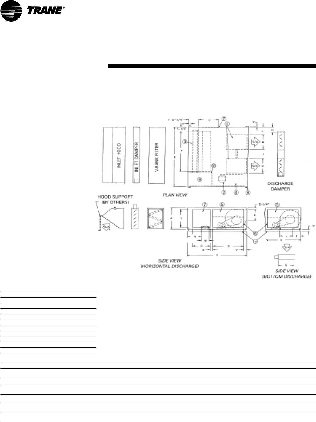
Table DW-3
Model A B C E F G H L M R S T
109 3' 0" 4' 4" 6' 5" 10-3/8" 1' 3-1/8" 1' 2-7/16"11-
11/16" 1' 2-½" 11-15/16" 1' 9" 2' 9" 2' 5"
(914) (1321) (1956) (264) (384) (367) (297) (368) (303) (533) (838) (737)
112 3' 0" 4' 4" 6' 5" 1' 1-9/16"1' 1-9/16"1' 2-7/16"11-
11/16" 1' 0-5/8"1' 3-15/16" 1' 9" 2' 9" 2' 5"
(914) (1321) (1956) (344) (344) (367) (297) (321) (405) (533) (838) (737)
115 3' 0" 4' 4" 6' 5" 1' 4" 1' 0-3/8" 1' 7-7/8"6-
15/16"11-
1/8" 1' 6-15/16" 1' 9" 2' 9" 2' 5"
(914) (1321) (1956) (406) (314) (505) (176) (283) (481) (533) (838) (737)
118 3' 0" 4' 4" 6' 5" 1' 7" 1' 0-3/8" 1' 7-7/8"6-
15/16"7-
7/8" 1' 10-1/16" 1' 9" 2' 9" 2' 5"
(914) (1321) (1956) (483) (314) (505) (176) (200) (560) (533) (838) (737)
Notes:
1. To permit blower shaft replacement, the side opposite the controls should have clearance equal to the unit width.
2. Minimum of 3’ for serviceability clearance.
Inlet Hood Support (By Others)
• The purpose of hood support is to
support the weight of the unit
accessories which are attached to the
inlet of the basic unit.
• The hood support can be made from
two, 2” x 2” x ¼” angle iron.
• One angle iron support should be
located in, or close to, the outer
corners of the hood. The supports can
be bolted to the hood.
Item Unit Components
1 Centrifugal Supply Fan
2 Fan Motor
3 Heat Source (Line Burner)
4 Control Cabinet
5 Hinged Control Cabinet Access Door
6 Motor and Drive Access Plate
7 Access Door
8 Removable Suspension Lifting Lug
9 Manifold Compartment
10 Observation Port
11 Unit Base
• The bottom of the angle iron support
should be fitted with a base. The base
can sit on the roof and does not have
to be fixed to the roof. An isolation pad
may be put between the base and the
roof.
Horizontal Arrangement — Single Blower
Return Air Opening Downstream of Burner
Motorized Return Air Damper — Motorized 75/25 Damper
109 112 115 118
MUA-PRC001-EN22
Dimension and
Weights
Inlet Hood Support (By Others)
• The purpose of hood support is to
support the weight of the unit
accessories which are attached to the
inlet of the basic unit.
• The hood support can be made from
two, 2” x 2” x ¼” angle iron.
• One angle iron support should be
located in, or close to, the outer corners
of the hood. The supports can be bolted
to the hood.
Horizontal Arrangement — Double Blower
Return Air Opening Downstream of Burner
Motorized Return Air Damper — Motorized 75/25 Damper
215 218 220 222 225 230
Table DW-4
Model A B C E F G H J L M N P R S T U W X Y
215 3' 0" 7' 10" 6' 5" 1' 4" 1' 0-3/8" 1' 7-7/8"7-
1/8" 1' 10-½" 7-7/8" 1’6-15/16" 1' 7" 5' 5-¾" 1’9” 2’9” 2’5” 1’9” 1' 2-¼" 4-½" 5-¾"
(914) (2388) (1956) (406) (314) (505) (181) (572) (200) (481) (483) (1670) (533) (838) 737) (533) (362) (114) (146)
218 3' 0" 7' 10" 6' 5" 1' 7" 1' 0-3/8" 1' 7-7/8"7-
1/8" 1' 4" 7-7/8" 1’10-1/16" 1' 7" 5' 5-¾" 1’9” 2’9” 2’5” 1’9” 1' 2-¼" 4-½" 5-¾"
(914) (2388) (1956) (483) (314) (505) (181) (406) (200) (560) (483) (1670) (533) (838) 737) (533) (362) (114) (146)
220 4' 0" 10' 10" 8' 0" 2' 0-7/8" 1' 1-3/16" 2' 4-¼" 11-½" 2' 5-½" 1' 0-3/8" 2’1-1/16" 1' 7" 7' 3-3/8" 2’9” 3’2” 3’3” 2’7” 1' 2-¼" 0' 8" 7-1/8"
(1219) (3302) (2438) (632) (335) (718) (292) (749) (314) (637) (483) (2219) (838) (965) (991) (787) (362) (203) (181)
222 4' 0" 10' 10" 8' 0" 2' 3-3/8" 1' 1-3/16" 2' 4-¼" 11-½" 2' 0-5/8" 1' 0-3/8" 2' 3-9/16" 1' 7" 7' 3-3/8" 2’9” 3’2” 3’3” 2’7” 1' 2-¼" 0' 8" 7-1/8"
(1219) (3302) (2438) (695) (335) (718) (292) (625) (314) (700) (483) (2219) (838) (965) (991) (787) (362) (203) (181)
225 5' 0" 12' 10" 8' 0" 2' 7-3/8" 1' 5-9/16" 3' 1-¾" 1' 2-½" 3' 1-5/8" 1' 3-3/8" 2' 7-½" 11-13/16" 9' 3-3/8" 2’1-¾” 3’2” 4’3” 1’8” 1' 8-¼" 1' 2" 6-¼"
(1524) (3912) (2438) (797) (446) (959) (368) (956) (391) (800) (300) (2829) (654) (965) (1295) (508) (514) (356) (159)
230 5' 0" 12' 10" 8' 0" 3' 0-7/8" 1' 5-9/16" 3' 1-¾" 1' 2-½" 2' 2-5/8" 1' 3-3/8" 3' 1" 11-13/16" 9' 3-3/8" 2’1-¾” 2’9” 4’3” 1’8” 1' 8-¼" 1' 2" 6-¼"
(1524) (3912) (2438) (937) (446) (959) (368) (676) (391) (940) (300) (2829) (654) (838) (1295) (508) (514) (356) (159)
Notes:
1. To permit blower shaft replacement, the side opposite the controls should have clearance equal to the unit width.
2. Minimum of 5’ for serviceability clearance.
3. Supply duct connection (by others) to be “pants-legged”from unit discharge.
Item Unit Components
1 Centrifugal Supply Fan
2 Fan Motor
3 Heat Source (Line Burner)
4 Control Cabinet
5 Hinged Control Cabinet Access Door
6 Motor and Drive Access Plate
7 Access Door
8 Removable Suspension Lifting Lug
9 Manifold Compartment
10 Observation Port
11 Unit Base
• The bottom of the angle iron support
should be fitted with a base. The base
can sit on the roof and does not have
to be fixed to the roof. An isolation pad
may be put between the base and the
roof.

23MUA-PRC001-EN
Dimension and
Weights
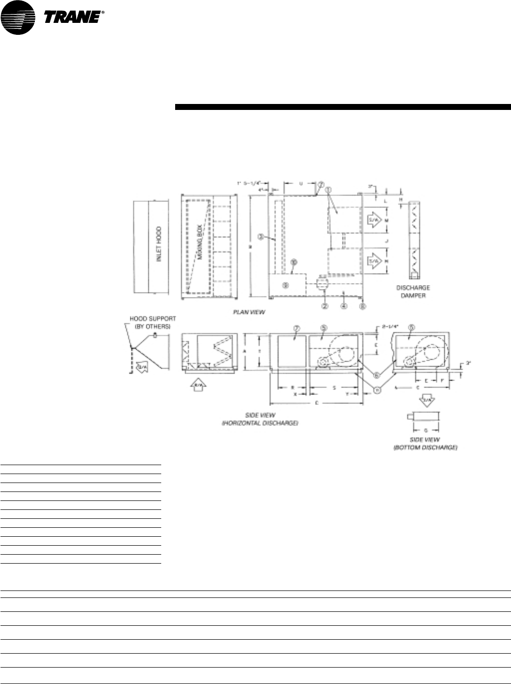
Table DW-5
Model A B C E F G H L M R S T
109 3' 0" 4' 4" 6' 5" 10-3/8" 1' 3-1/8" 1' 2-7/16"11-
11/16" 1' 2-½" 11-15/16" 1' 9" 2' 9" 2' 5"
(914) (1321) (1956) (264) (384) (367) (297) (368) (303) (533) (838) (737)
112 3' 0" 4' 4" 6' 5" 1' 1-9/16"1' 1-9/16"1' 2-7/16"11-
11/16" 1' 0-5/8"1' 3-15/16" 1' 9" 2' 9" 2' 5"
(914) (1321) (1956) (344) (344) (367) (297) (321) (405) (533) (838) (737)
115 3' 0" 4' 4" 6' 5" 1' 4" 1' 0-3/8" 1' 7-7/8"6-
15/16"11-
1/8" 1' 6-15/16" 1' 9" 2' 9" 2' 5"
(914) (1321) (1956) (406) (314) (505) (176) (283) (481) (533) (838) (737)
118 3' 0" 4' 4" 6' 5" 1' 7" 1' 0-3/8" 1' 7-7/8"6-
15/16"7-
7/8" 1' 10-1/16" 1' 9" 2' 9" 2' 5"
(914) (1321) (1956) (483) (314) (505) (176) (200) (560) (533) (838) (737)
Notes:
1. To permit blower shaft replacement, the side opposite the controls should have clearance equal to the unit width.
2. Minimum of 3’ for serviceability clearance.
Inlet Hood Support (By Others)
• The purpose of hood support is to
support the weight of the unit
accessories which are attached to the
inlet of the basic unit.
• The hood support can be made from
two, 2” x 2” x ¼” angle iron.
• One angle iron support should be
located in, or close to, the outer
corners of the hood. The supports can
be bolted to the hood.
• The bottom of the angle iron support
should be fitted with a base. The base
can sit on the roof and does not have
to be fixed to the roof. An isolation
pad may be put between the base
and the roof.
Item Unit Components
1 Centrifugal Supply Fan
2 Fan Motor
3 Heat Source (Line Burner)
4 Control Cabinet
5 Hinged Control Cabinet Access Door
6 Motor and Drive Access Plate
7 Access Door
8 Removable Suspension Lifting Lug
9 Manifold Compartment
10 Observation Port
11 Unit Base
Horizontal Arrangement — Single Blower
With Mixing Box
109 112 115 118
MUA-PRC001-EN24
Dimension and
Weights
Inlet Hood Support (By Others)
• The purpose of hood support is to
support the weight of the unit
accessories which are attached to the
inlet of the basic unit.
• The hood support can be made from
two, 2” x 2” x ¼” angle iron.
• One angle iron support should be
located in, or close to, the outer corners
of the hood. The supports can be bolted
to the hood.
Table DW-6
Model A B C E F G H J L M R S T U X Y
215 3' 0" 7' 10" 6' 5" 1' 4" 1' 0-3/8" 1' 7-7/8"7-
1/8" 1' 10-½" 7-7/8" 1' 6-15/16" 1' 9" 2' 9" 2' 9" 1' 9" 4-½" 5-¾"
(914) (2388) (1956) (406) (314) (505) (181) (572) (200) (481) (533) (838) (838) (533) (114) (146)
218 3' 0" 7' 10" 6' 5" 1' 7" 1' 0-3/8" 1' 7-7/8"7-
1/8" 1' 4" 7-7/8" 1' 10-1/16" 1' 9" 2' 9" 2' 9" 1' 9" 4-½" 5-¾"
(914) (2388) (1956) (483) (314) (505) (181) (406) (200) (560) (533) (838) (838) (533) (114) (146)
220 4' 0" 10' 10" 8' 0" 2' 0-7/8" 1' 1-3/16" 2' 4-¼" 11-½" 2' 5-½" 1' 0-3/8" 2' 1-1/16" 2' 7" 3' 2" 3' 3" 2' 7" 0' 8" 7-1/8"
(1219) (3302) (2438) (632) (335) (718) (292) (749) (314) (637) (787) (965) (991) (787) (203) (181)
222 4' 0" 10' 10" 8' 0" 2' 3-3/8" 1' 1-3/16" 2' 4-¼" 11-½" 2' 0-5/8" 1' 0-3/8" 2' 3-9/16” 2' 7" 3' 2" 3' 3" 2' 7" 0' 8" 7-1/8"
(1219) (3302) (2438) (695) (335) (718) (292) (625) (314) (700) (787) (965) (991) (787) (203) (181)
225 5' 0" 12' 10" 8' 0" 2' 7-3/8" 1' 5-9/16" 3' 1-¾" 1' 2-½" 3' 1-5/8" 1' 3-3/8" 2' 7-½" 2' 1-¾" 2' 9" 4' 3" 1' 8" 1' 2" 6-¼"
(1524) (3912) (2438) (797) (446) (959) (368) (956) (391) (800) (654) (838) (1295) (508) (356) (159)
230 5' 0" 12' 10" 8' 0" 3' 0-7/8" 1' 5-9/16" 3' 1-¾" 1' 2-½" 2' 2-5/8" 1' 3-3/8" 3' 1" 2' 1-¾" 2' 9" 4' 3" 1' 8" 1' 2" 6-¼"
(1524) (3912) (2438) (937) (446) (959) (368) (676) (391) (940) (654) (838) (1295) (508) (356) (159)
Notes:
1. To permit blower shaft replacement, the side opposite the controls should have clearance equal to the unit width.
2. Minimum of 5’ for serviceability clearance.
3. Supply duct connection (by others) to be “pants-legged” from unit discharge.
Item Unit Components
1 Centrifugal Supply Fan
2 Fan Motor
3 Heat Source (Line Burner)
4 Control Cabinet
5 Hinged Control Cabinet Access Door
6 Motor and Drive Access Plate
7 Access Door
8 Removable Suspension Lifting Lug
9 Manifold Compartment
10 Observation Port
11 Unit Base
• The bottom of the angle iron support
should be fitted with a base. The base
can sit on the roof and does not have
to be fixed to the roof. An isolation
pad may be put between the base
and the roof.
Horizontal Arrangement — Double Blower
With Mixing Box
215 218 220 222 225 230
25MUA-PRC001-EN
Dimension and
Weights
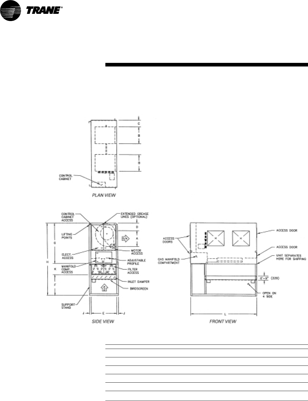
Table DW-7
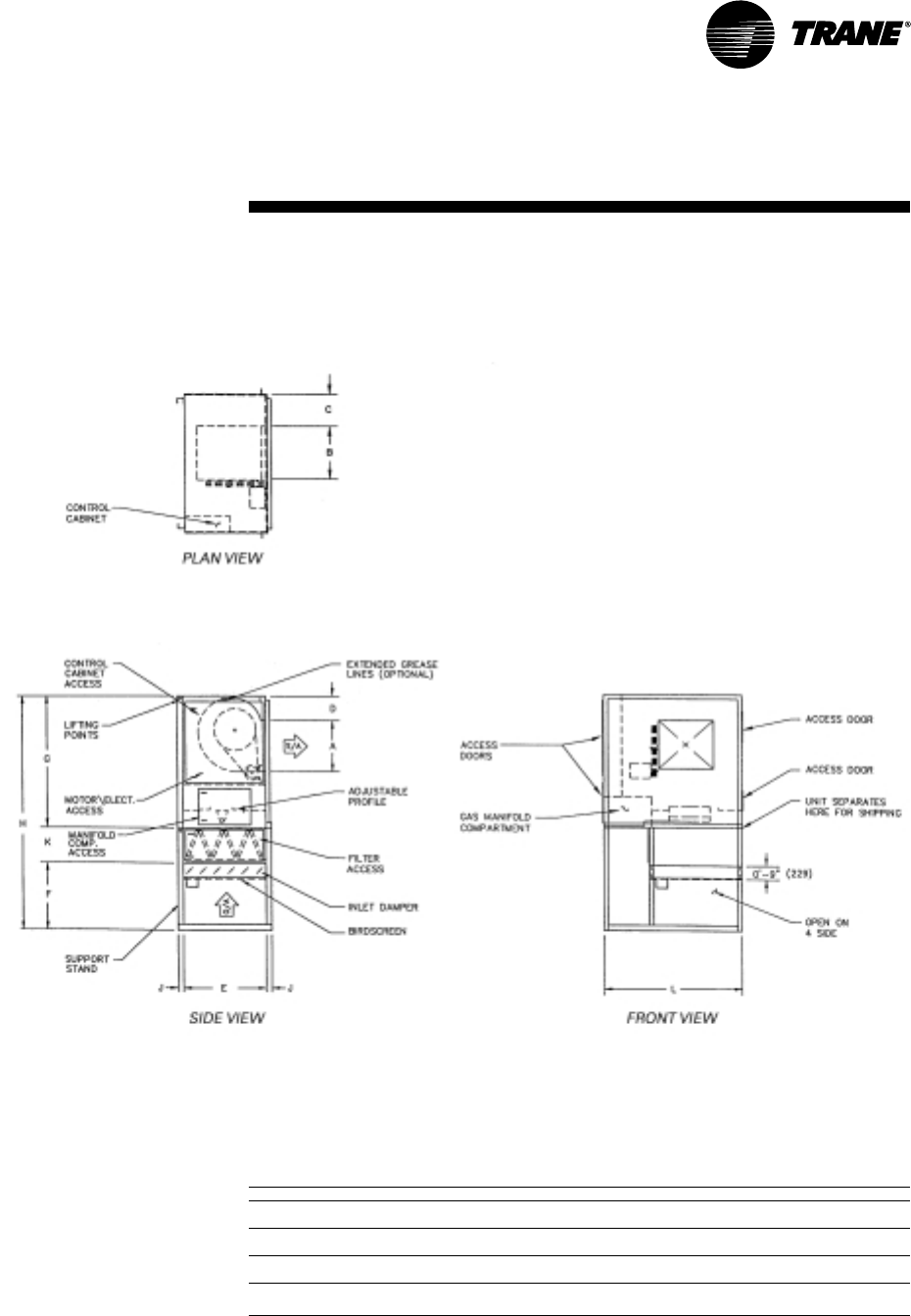
Model A B C D E F G H J K L
109 10-3/8"11-
15/16" 1' 2-½" 1' 3-1/8" 3' 0" 3' 0" 6' 5" 11' 3" 0' 3" 1' 10" 4' 4"
(264) (303) (368) (384) (914) (914) (1956) (3429) (76) (559) (1321)
112 1' 1-9/16" 1' 3-15/16" 1' ½" 1' 1-9/16" 3' 0" 3' 0" 6' 5" 11' 3" 0' 3" 1' 10" 4' 4"
(344) (405) (318) (344) (914) (914) (1956) (3429) (76) (559) (1321)
115 1' 4" 1' 6-15/16"11-
1/8" 1' 3/8" 3' 0" 3' 0" 6' 5" 11' 3" 0' 3" 1' 10" 4' 4"
(406) (481) (283) (314) (914) (914) (1956) (3429) (76) (559) (1321)
118 1' 7" 1' 10-1/16"7-
7/8" 1' 3/8" 3' 0" 3' 0" 6' 5" 11' 3" 0' 3" 1' 10" 4' 4"
(483) (560) (200) (314) (914) (914) (1956) (3429) (76) (559) (1321)
Notes:
1. Factory furnished support stand shipped separately for field mounting by others.
2. V-bank and inlet damper shown are optional components.
3. If V-bank section is ordered, it will ship mounted to the support stand.
4. If inlet damper is ordered, it will ship mounted in the support stand.
5. Refer to page 35 for unit weights.
Vertical Arrangement — Single Blower
100% Outside Air—Arrangement 4
MUA-PRC001-EN26
Dimension and
Weights
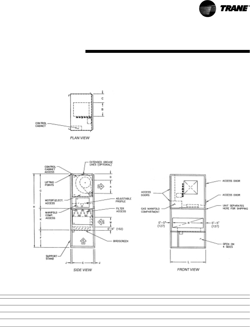
Table DW-8
Model A B C D E F G H J K L P
215 1' 4" 1' 6-15/16"0' 7-7/8" 1' 0-3/8" 3' 0" 3' 0" 6' 5" 11' 3" 0' 3" 1' 10" 7' 10" 1‘ 10-¼"
(406) (481) (200) (314) (914) (914) (1956) (3429) (76) (559) (2388) (565)
218 1' 7" 1' 10-1/16"0' 7-7/8" 1' 0-3/8" 3' 0" 3' 0" 6' 5" 11' 3" 0' 3" 1' 10" 7' 10" 1' 4"
(483) (560) (200) (314) (914) (914) (1956) (3429) (76) (559) (2388) (406)
220 2' 0-7/8" 2' 1-1/16" 1' 0-3/8" 1‘ 1-3/16” 4’ 0" 4' 0" 8' 0" 13' 10" 0' 4" 1' 10" 10' 10" 2' 5-5/8"
(632) (637) (314) (335) (1219) (1219) (2438) (4216) (102) (559) (3302) (752)
222 2' 3-3/8" 2' 3-9/16" 1' 0-3/8" 1‘ 1-3/16” 4’ 0" 4' 0" 8' 0" 13' 10" 0' 4" 1' 10" 10' 10" 2' 5-5/8"
(695) (700) (314) (335) (1219) (1219) (2438) (4216) (102) (559) (3302) (752)
225 2' 7-3/8" 2' 7-½" 1' 3-3/8"1‘ 5-9/16” 5’ 0" 4' 0" 8' 0" 14' 4" 0' 4" 2' 4" 12' 10" 3' 1-5/8"
(797) (800) (391) (446) (1524) (1219) (2438) (4369) (102) (711) (3912) (956)
230 3' 0-7/8" 3' 1" 1' 3-3/8"1‘ 5-9/16” 5’ 0" 4' 0" 8' 0" 14' 4" 0' 4" 2' 4" 12' 10" 2' 2-5/8"
(937) (940) (391) (446) (1524) (1219) (2438) (4369) (102) (711) (3912) (676)
Notes:
1. Supply duct connection (by others) to be “pants-legged” from unit discharge
2. Factory furnished support stand shipped separately for field mounting by others.
3. V-bank and inlet damper shown are optional components.
4. If V-bank section is ordered, it will ship mounted to the support stand.
5. If inlet damper is ordered, it will ship mounted in the support stand.
6. Refer to page 35 for unit weights.
Vertical Arrangement —Double Blower
100% Outside Air—Arrangement 4
27MUA-PRC001-EN
Dimension and
Weights
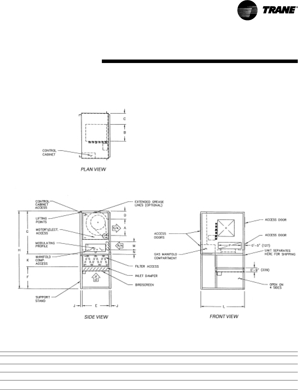
Table DW-9
Model A B C D E F G H J K L M N P
109 10-3/8"11-
15/16" 1' 2-½" 1' 3-1/8" 3' 0" 3' 0" 6' 5" 11' 3" 0' 3" 1' 10" 4' 4" 1' 2-¼" 1' 7" 2' 3-¾"
(264) (303) (368) (384) (914) (914) (1956) (3429) (76) (559) (1321) (362) (483) (705)
112 1' 1-9/16" 1' 3-15/16" 1' ½" 1' 1-9/16" 3' 0" 3' 0" 6' 5" 11' 3" 0' 3" 1' 10" 4' 4" 1' 2-¼" 1' 7" 2' 3-¾"
(344) (405) (318) (344) (914) (914) (1956) (3429) (76) (559) (1321) (362) (483) (705)
115 1' 4" 1' 6-15/16"11-
1/8" 1' 3/8" 3' 0" 3' 0" 6' 5" 11' 3" 0' 3" 1' 10" 4' 4" 1' 2-¼" 1' 7" 2' 3-¾"
(406) (481) (283) (314) (914) (914) (1956) (3429) (76) (559) (1321) (362) (483) (705)
118 1' 7" 1' 10-1/16"7-
7/8" 1' 3/8" 3' 0" 3' 0" 6' 5" 11' 3" 0' 3" 1' 10" 4' 4" 1' 2-¼" 1' 7" 2' 3-¾"
(483) (560) (200) (314) (914) (914) (1956) (3429) (76) (559) (1321) (362) (483) (705)
Notes:
1. Factory furnished support stand shipped separately for field mounting by others.
2. V-bank and inlet damper shown are optional components.
3. If V-bank section is ordered, it will ship mounted to the support stand.
4. If inlet damper is ordered, it will ship mounted in the support stand.
5. Refer to page 35 for unit weights.
Vertical Arrangement — Single Blower
Return Air Downstream of Burner—Arrangement 4
MUA-PRC001-EN28
Dimension and
Weights
Table DW-10
Model A B C D E F G H J K L M N P R
215 1' 4" 1' 6-15/16"7-
7/8" 1' 0-3/8" 3' 0" 3' 0" 6' 5" 11' 3" 0' 3" 1' 10" 7' 10" 1' 2-¼" 1' 7" 5' 5-¾" 1' 10-¼"
(406) (481) (200) (314) (914) (914) (1956) (3429) (76) (559) (2388) (362) (483) (1670) (565)
218 1' 7" 1' 10-1/16"7-
7/8" 1' 3/8" 3' 0" 3' 0" 6' 5" 11' 3" 0' 3" 1' 10" 7' 10" 1' 2-¼" 1' 7" 5' 5-¾" 1' 4"
(483) (560) (200) (314) (914) (914) (1956) (3429) (76) (559) (2388) (362) (483) (1670) (406)
220 2' 0-7/8" 2' 1-1/16" 1' 0-3/8" 1' 1-3/16" 4' 0" 4' 0" 8' 0" 13' 10" 0' 4" 1' 10" 10' 10" 1' 2-¼" 1' 7" 7' 3-3/8" 2' 5-5/8"
(632) (637) (314) (335) (1219) (1219) (2438) (4216) (102) (559) (3302) (362) (483) (2219) (752)
222 2' 3-3/8" 2' 3-9/16" 1' 0-3/8" 1' 1-3/16" 4' 0" 4' 0" 8' 0" 13' 10" 0' 4" 1' 10" 10' 10" 1' 2-¼" 1' 7" 7' 3-3/8" 2' 5-5/8"
(695) (700) (314) (335) (1219) (1219) (2438) (4216) (102) (559) (3302) (362) (483) (2219) (752)
225 2' 7-3/8" 2' 7-½" 1' 3-3/8" 1' 5-9/16" 5' 0" 4' 0" 8' 0" 14' 4" 0' 4" 2' 4" 12' 10" 1' 8-¼" 1' 0-5/16" 9' 3-3/8" 3' 1-5/8"
(797) (800) (391) (446) (1524) (1219) (2438) (4369) (102) (711) (3912) (514) (313) (2829) (956)
230 3' 0-7/8" 3' 1" 1' 3-3/8" 1' 5-9/16" 5' 0" 4' 0" 8' 0" 14' 4" 0' 4" 2' 4" 12' 10" 1' 8-¼" 1' 0-5/16" 9' 3-3/8" 2' 2-5/8"
(937) (940) (391) (446) (1524) (1219) (2438) (4369) (102) (711) (3912) (514) (313) (2829) (676)
Notes:
1. Supply duct connection (by others) to be “pants-legged” from unit discharge.
2. Factory furnished support stand shipped separately for field mounting by others.
3. V-bank and inlet damper shown are optional components.
4. If V-bank section is ordered, it will ship mounted to the support stand.
5. If inlet damper is ordered, it will ship mounted in the support stand.
6. Refer to page 35 for unit weights.
Vertical Arrangement — Double Blower
Return Air Downstream of Burner—Arrangement 4
29MUA-PRC001-EN
Dimension and
Weights
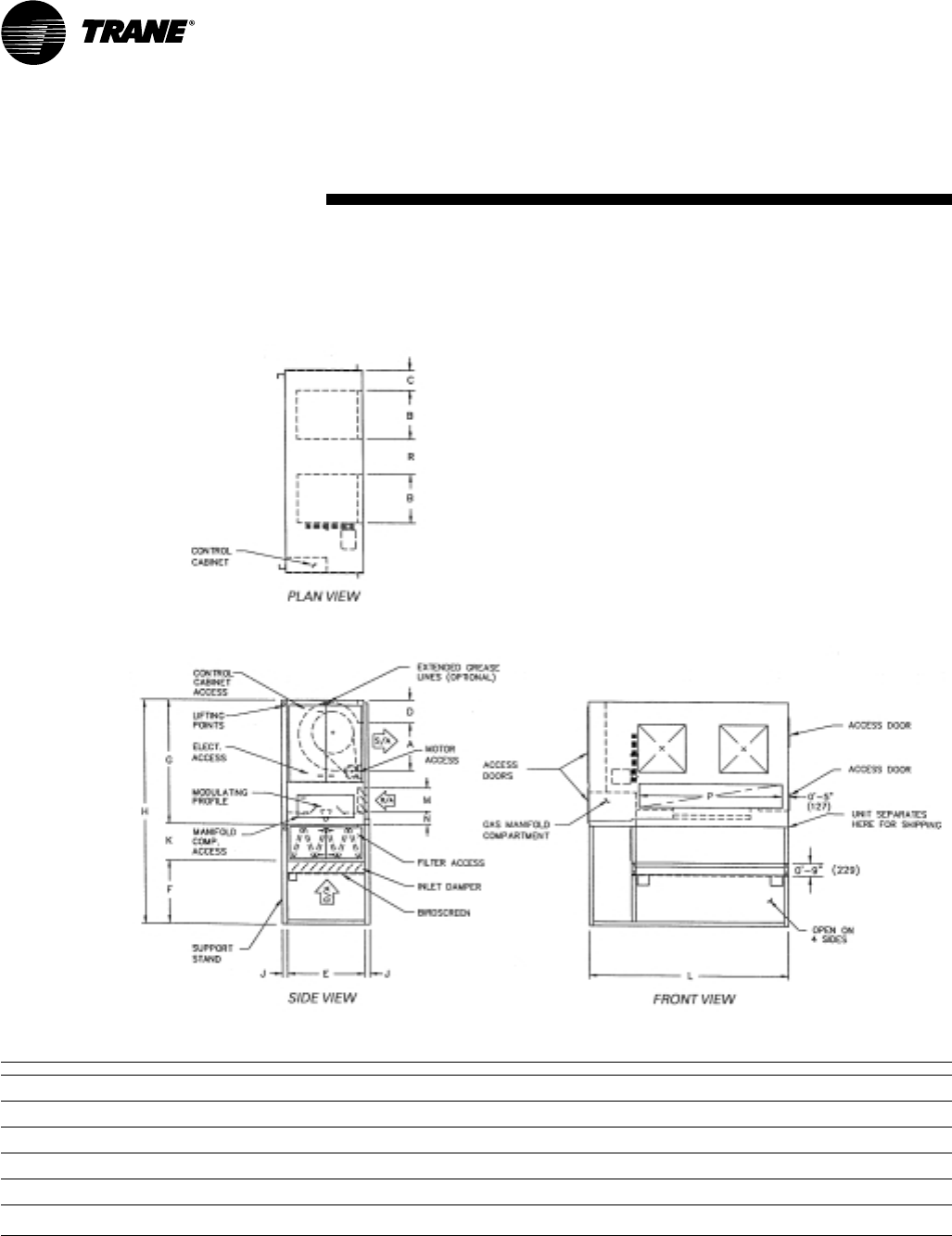
Table DW-11
Model A B C D E F G H J K L M N
109 10-3/8"11-
15/16" 1' 2-½" 1' 3-1/8" 3' 0" 3' 0" 6' 5" 13' 11" 0' 3" 4' 6" 4' 4" 1' 8-¼" 3' 6"
(264) (303) (368) (384) (914) (914) (1956) (4242) (76) (1372) (1321) (514) (1067)
112 1' 1-9/16" 1' 3-15/16" 1' ½" 1' 1-9/16" 3' 0" 3' 0" 6' 5" 13' 11" 0' 3" 4' 6" 4' 4" 1' 8-¼" 3' 6"
(344) (405) (318) (344) (914) (914) (1956) (4242) (76) (1372) (1321) (514) (1067)
115 1' 4" 1' 6-15/16"11-
1/8" 1' 3/8" 3' 0" 3' 0" 6' 5" 13' 11" 0' 3" 4' 6" 4' 4" 1' 8-¼" 3' 6"
(406) (481) (283) (314) (914) (914) (1956) (4242) (76) (1372) (1321) (514) (1067)
118 1' 7" 1' 10-1/16"7-
7/8" 1' 3/8" 3' 0" 3' 0" 6' 5" 13' 11" 0' 3" 4' 6" 4' 4" 1' 8-¼" 3' 6"
(483) (560) (200) (314) (914) (914) (1956) (4242) (76) (1372) (1321) (514) (1067)
Notes:
1. Factory furnished support stand shipped separately for field mounting by others.
2. V-bank and inlet damper shown are optional components.
3. If V-bank section is ordered, it will ship mounted to the support stand.
4. If inlet damper is ordered, it will ship mounted in the support stand.
5. Refer to page 35 for unit weights.
Vertical Arrangement
Single Blower with Mixing Box—Arrangement 4
MUA-PRC001-EN30
Dimension and
Weights
Table DW-12
Model A B C D E F G H J K L M N P
215 1' 4" 1' 6-15/16"7-
7/8" 1' 3/8" 3' 0" 3' 0" 6' 5" 13' 11" 0' 3" 4' 6" 7' 10" 1' 8-¼" 7' 0" 1' 10-¼"
(406) (481) (200) (314) (914) (914) (1956) (4242) (76) (1372) (2388) (514) (2134) (565)
218 1' 7" 1' 10-1/16"7-
7/8" 1' 3/8" 3' 0" 3' 0" 6' 5" 13' 11" 0' 3" 4' 6" 7' 10" 1' 8-¼" 7' 0" 1' 4"
(483) (560) (200) (314) (914) (914) (1956) (4242) (76) (1372) (2388) (514) (2134) (406)
220 2' 0-7/8" 2' 1-1/16" 1' 0-3/8" 1' 1-3/16" 4' 0" 4' 0" 8' 0" 17' 0" 0' 4" 5' 0" 10' 10" 1' 8-¼" 10' 0" 2' 5-½"
(632) (637) (314) (335) (1219) (1219) (2438) (5182) (102) (1524) (3302) (514) (3048) (749)
222 2' 3-3/8" 2' 3-9/16" 1' 0-3/8" 1' 1-3/16" 4' 0" 4' 0" 8' 0" 17' 0" 0' 4" 5' 0" 10' 10" 1' 8-¼" 10' 0" 2' 0-5/8"
(695) (700) (314) (335) (1219) (1219) (2438) (5182) (102) (1524) (3302) (514) (3048) (625)
225 2' 7-3/8" 2' 7-½" 1' 3-3/8" 1' 5-9/16" 5' 0" 4' 0" 8' 0" 17' 5" 0' 4" 5' 5" 12' 10" 2' 2-¼" 12' 0" 3' 1-5/8"
(797) (800) (391) (446) (1524) (1219) (2438) (5309) (102) (1651) (3912) (667) (3658) (957)
230 3' 0-7/8" 3' 1" 1' 3-3/8" 1' 5-9/16" 5' 0" 4' 0" 8' 0" 17' 5" 0' 4" 5' 5" 12' 10" 2' 2-¼" 12' 0" 2' 2-5/8"
(937) (940) (391) (446) (1524) (1219) (2438) (5309) (102) (1651) (3912) (667) (3658) (676)
Notes:
1. Supply duct connection (by others) to be “pants-legged” from unit discharge
2. Factory furnished support stand shipped separately for field mounting by others.
3. V-bank and inlet damper shown are optional components.
4. If V-bank section is ordered, it will ship mounted to the support stand.
5. If inlet damper is ordered, it will ship mounted in the support stand.
6. Refer to page 35 for unit weights.
Vertical Arrangement
Double Blower With Mixing Box—Arrangement 4
31MUA-PRC001-EN
Dimension and
Weights
Table DW-13
Model R/A/I.D.
109-118 3' 6" x 1' 8-¼"
(1067 x 514)
215-218 7' x 1' 8-¼"
(2134 x 514)
220-222 10' x 1' 8-¼"
(3048 x 514)
225-230 12' x 2' 2-½"
(3658 x 673)
Table DW-14
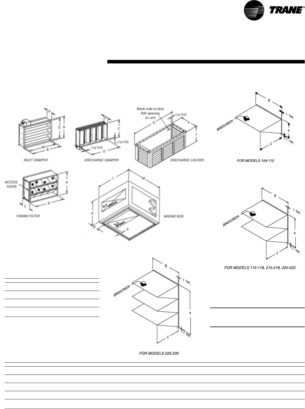
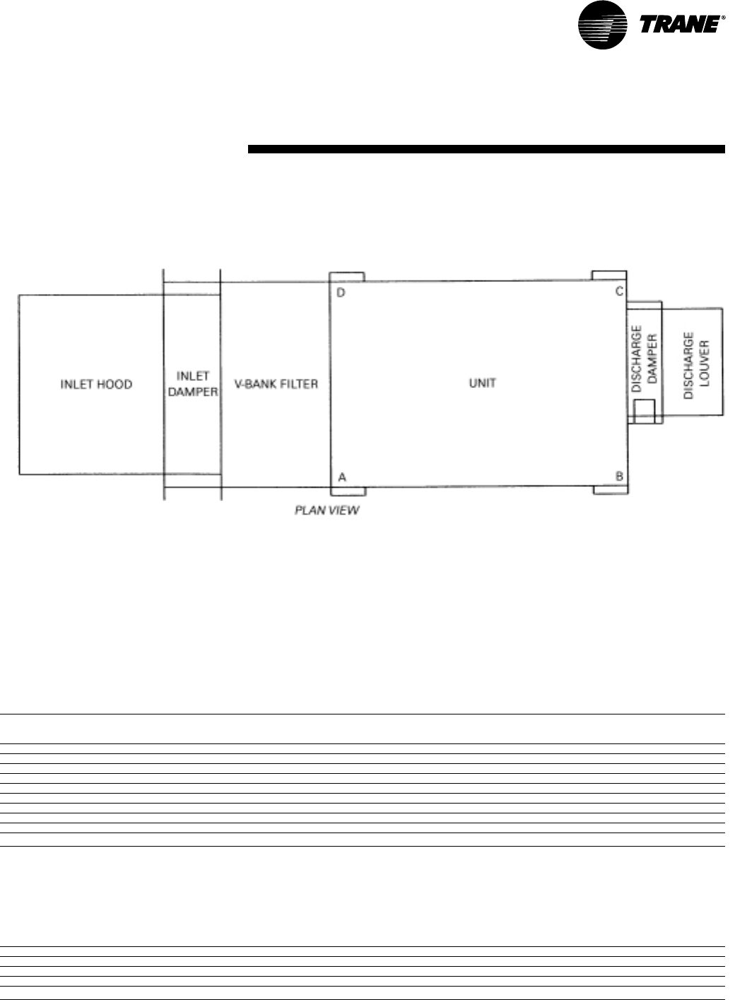
Model A B C D E F G H J K L M Filters [Qty] Size
109-112 3' 0" 3' 11-¼" 1' 5-7/16" 1' 8-13/16" 1' 10" 5' 1-¾" 2' 8-¼" 3' 7-1/8" 1' 9" 1' 11" 4' 4" 4' 6" [9] 15x20x2"
(914) (1200) (443) (529) (559) (1568) (819) (1095) (533) (584) (1321) (1372)([9] 381x508x51)
115-118 3' 0" 3' 11-¼" 1' 10-7/8" 2' 2-15/16" 1' 10" 5' 1-¾" 2' 8-¼" 3' 7-1/8" 2' 0" 2' 2" 4' 4" 4' 6" [9] 15x20x2"
(914) (1200) (581) (684) (559) (1568) (819) (1095) (610) (660) (1321) (1372)([9] 381x508x51)
215-218 3' 0" 7' 7-½" 1' 10-7/8" 5' 4-7/8" 1' 10" 5' 1-¾" 2' 8-¼" 7' 3-3/8" 2' 0" 2' 2" 7' 10" 4' 6" [18] 15x20x2"
(914) (2324) (581) (1648) (559) (1568) (819) (2219) (610) (660) (2388) (1372)([18] 381x508x51)
220-222 4' 0" 8' 5-5/8" 2' 7-¼" 7' 0-½" 1' 10" 5' 5-¾" 3' 8-¼" 8' 1-½" 3' 9" 2' 7" 10' 10" 5' 0" [25] 20x20x2"
(1219) (2581) (794) (2146) (559) (1670) (1124) (2477) (1143) (787) (3302) (1524)([25] 508x508x51)
225-230 5' 0" 10' 1-3/8" 3' 4-¾" 8' 9-3/8" 2' 4" 7' 2-1/8" 4' 8-¼" 9' 9-¼" 3' 9" 3' 4-¾" 12' 10" 5' 5" [36] 20x25x2"
(1524) (3083) (1035) (2677) (711) (2188) (1429) (2978) (1143) (1035) (3912) (1651)([36] 508x635x51)
Note:
*Permanent filters are constructed of aluminum mesh.
NOTE: ALL DIMENSIONS IN INCHES
SUBJECT TO MANUFACTURING
TOLERANCES.
Accessories
MUA-PRC001-EN32
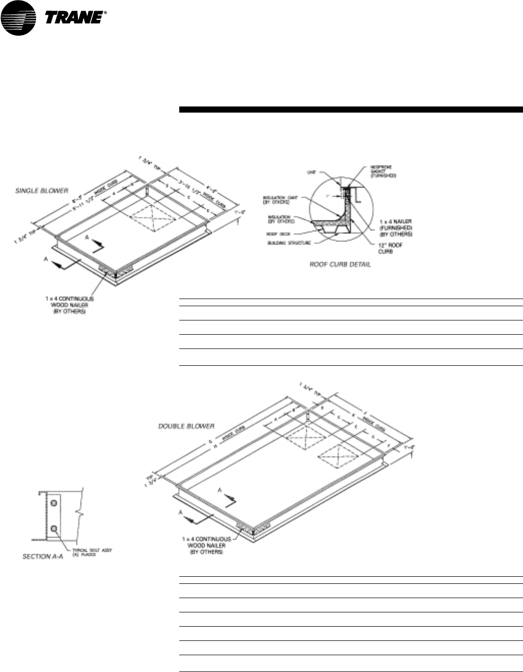
Dimension and
Weights
Table DW-15
Model A B C D E
109 10-3/8" 1' 0-3/8"11-
15/16" 11-¾" 1' 10-13/16"
(264) (314) (303) (298) (579)
112 1' 1-9/16"10-
13/16" 1' 3-15/16"9-
7/8" 1' 8-7/8"
(344) (275) (405) (251) (530)
115 1' 4" 9-5/8" 1' 6-15/16"8-
3/8" 1' 7-3/8"
(406) (244) (481) (213) (492)
118 1' 7" 9-5/8" 1' 10-1/16"5-
1/8" 1' 7-3/8"
(483) (244) (560) (130) (492)
Table DW-16
Model A B C D E F G H J K
215 1' 4" 9-5/8" 1' 6-15/16"5-
1/8" 1' 10-½" 1' 11-3/8" 6' 3" 5' 11-½" 7' 8" 7' 4-½"
(406) (244) (481) (130) (572) (594) (1905) (1816) (2337) (2248)
218 1' 7" 9-5/8" 1' 10-1/16"5-
1/8" 1' 4" 1' 11-3/8" 6' 3" 5' 11-½" 7' 8" 7' 4-½"
(483) (244) (560) (130) (406) (594) (1905) (1816) (2337) (2248)
220 2' 0-7/8"10-
7/16" 2' 1-1/16"9-
5/8" 2' 5-½" 2' 11-½" 7' 10" 7' 6-½" 10' 8" 10' 4-½"
(632) (265) (637) (244) (749) (902) (2388) (2299) (3251) (3162)
222 2' 3-3/8"10-
7/16" 2' 3-9/16"9-
5/8" 2' 0-5/8" 2' 11-½" 7' 10" 7' 6-½" 10' 8" 10' 4-½"
(695) (265) (700) (244) (625) (902) (2388) (2299) (3251) (3162)
225 2' 7-3/8" 1' 2-13/16" 2' 7-½" 1' 0-5/8" 3' 1-5/8" 2' 11-½" 7' 10" 7' 6-½" 12' 8" 12' 4-½"
(797) (376) (800) (321) (956) (902) (2388) (2299) (3861) (3772)
230 3' 0-7/8" 1' 2-13/16" 3' 1" 1' 0-5/8" 2' 2-5/8" 2' 11-½" 7' 10" 7' 6-½" 12' 8" 12' 4-½"
(937) (376) (940) (321) (676) (902) (2388) (2299) (3861) (3772)
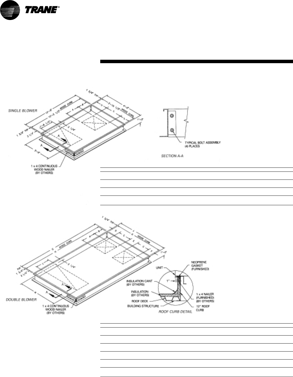
Notes:
1. Curb to be shipped loose and assembled in the field.
2. Curb must be square and level.
3. Curb requires intermediate structural support and is not to be corner post mounted.
4. Gaskets to be shipped with unit.
5. Bolting accessories shipped with curb.
6. Curb drawings shown are for units which have controls on the “standard” side.
7. Available on horizontal units only.
Roof Curbs
33MUA-PRC001-EN
Dimension and
Weights
Table DW-17
Model A B C D E
109 10-3/8" 1' 0-3/8"11-
15/16" 11-¾" 1' 10-13/16"
(264) (314) (303) (298) (579)
112 1' 1-9/16"10-
13/16" 1' 3-15/16"9-
7/8" 1' 8-7/8"
(344) (275) (405) (251) (530)
115 1' 4" 9-5/8" 1' 6-15/16"8-
3/8" 1' 7-3/8"
(406) (244) (481) (213) (492)
118 1' 7" 9-5/8" 1' 10-1/16"5-
1/8" 1' 7-3/8"
(483) (244) (560) (130) (492)
Table DW-18
Model A B C D E F G H J K L M W
215 1' 4" 9-5/8" 1' 6-15/16"5-
1/8" 1' 10-½" 1' 11-3/8" 6' 3" 5' 11-½" 7' 8" 7' 4-½" 5' 5-¾" 1' 4-¼" 1' 2-¼"
(406) (244) (481) (130) (572) (594) (1905) (1816) (2337) (2248) (1670) (413) (362)
218 1' 7" 9-5/8" 1' 10-1/16"5-
1/8" 1' 4" 1' 11-3/8" 6' 3" 5' 11-½" 7' 8" 7' 4-½" 5' 5-¾" 1' 4-¼" 1' 2-¼"
(483) (244) (560) (130) (406) (594) (1905) (1816) (2337) (2248) (1670) (413) (362)
220 2' 0-7/8"10-
7/16" 2' 1-1/16"9-
5/8" 2' 5-½" 2' 11-½" 7' 10" 7' 6-½" 10' 8" 10' 4-½" 7' 3-3/8" 1' 4-¼" 1' 2-¼"
(632) (265) (637) (244) (749) (902) (2388) (2299) (3251) (3162) (2219) (413) (362)
222 2' 3-3/8"10-
7/16" 2' 3-9/16"9-
5/8" 2' 0-5/8" 2' 11-½" 7' 10" 7' 6-½" 10' 8" 10' 4-½" 7' 3-3/8" 1' 4-¼" 1' 2-¼"
(695) (265) (700) (244) (625) (902) (2388) (2299) (3251) (3162) (2219) (413) (362)
225 2' 7-3/8" 1' 2-13/16" 2' 7-½" 1' 0-5/8" 3' 1-5/8" 2' 11-½" 7' 10" 7' 6-½" 12' 8" 12' 4-½" 9' 3-3/8"9-
1/16" 1' 8-¼"
(797) (376) (800) (321) (956) (902) (2388) (2299) (3861) (3772) (2829) (230) (514)
230 3' 0-7/8" 1' 2-13/16" 3' 1" 1' 0-5/8" 2' 2-5/8" 2' 11-½" 7' 10" 7' 6-½" 12' 8" 12' 4-½" 9' 3-3/8"9-
1/16" 1' 8-¼"
(937) (376) (940) (321) (676) (902) (2388) (2299) (3861) (3772) (2829) (230) (514)
Notes:
1. Curb to be shipped loose and assembled in the field.
2. Curb must be square and level.
3. Curb requires intermediate structural support and is not to be corner post mounted.
4. Gaskets to be shipped with unit.
5. Bolting accessories shipped with curb.
6. Curb drawings shown are for units which have controls on the “standard” side.
7. Available on horizontal units only.
Roof Curbs for Units with Return
Air Opening Downstream of Burner
MUA-PRC001-EN34
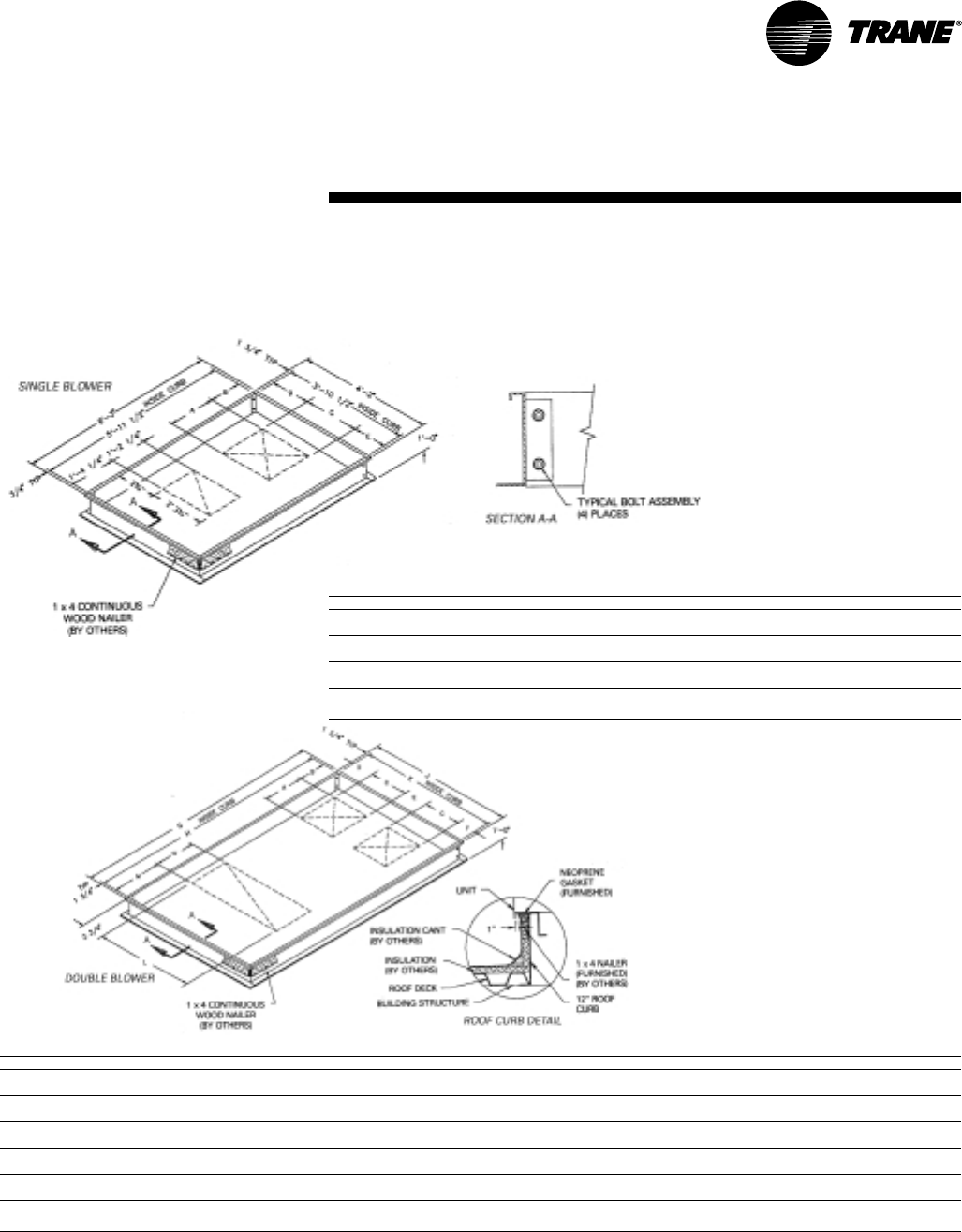
Dimension and
Weights
Table DW-19
Model A B C D E
109 10-3/8" 1' 0-3/8"11-
15/16" 11-¾" 1' 10-13/16"
(264) (314) (303) (298) (579)
112 1' 1-9/16"10-
13/16" 1' 3-15/16"9-
7/8" 1' 8-7/8"
(344) (275) (405) (251) (530)
115 1' 4" 9-5/8" 1' 6-15/16"8-
3/8" 1' 7-3/8"
(406) (244) (481) (213) (492)
118 1' 7" 9-5/8" 1' 10-1/16"5-
1/8" 1' 7-3/8"
(483) (244) (560) (130) (492)
Table DW-20
Model A B C D E F G H J K L M
215 1' 4" 9-5/8" 1' 6-15/16"5-
1/8" 1' 10-½"1' 11-3/8" 10' 9" 10' 5-½" 7' 8" 7' 4-½" 1' 8-¼" 7' 0"
(406) (244) (481) (130) (572) (594) (3277) (3188) (2337) (2248) (514) (2134)
218 1' 7" 9-5/8" 1' 10-1/16"5-
1/8" 1' 4" 1' 11-3/8" 10' 9" 10' 5-½" 7' 8" 7' 4-½" 1' 8-¼" 7' 0"
(483) (244) (560) (130) (406) (594) (3277) (3188) (2337) (2248) (514) (2134)
220 2' 0-7/8"10-
7/16" 2' 1-1/16"9-
5/8" 2' 5-½" 2' 11-½" 12' 10" 12' 6-½" 10' 8" 10' 4-½" 1' 8-¼" 10' 0"
(632) (265) (637) (244) (749) (902) (3912) (3823) (3251) (3162) (514) (3048)
222 2' 3-3/8"10-
7/16" 2' 3-9/16"9-
5/8" 2' 0-5/8" 2' 11-½" 12' 10"12' 6-½" 10' 8" 10' 4-½"1' 8-¼" 10' 0"
(695) (265) (700) (244) (625) (902) (3912) (3823) (3251) (3162) (514) (3048)
225 2' 7-3/8"1' 2-13/16"2' 7-½" 1' 0-5/8" 3' 1-5/8" 2' 11-½" 13' 4" 13'-½" 12' 8" 12' 4-½"2' 2-½" 12' 0"
(797) (376) (800) (321) (956) (902) (4064) (3950) (3861) (3772) (673) (3658)
230 3' 0-7/8"1' 2-13/16" 3' 1" 1' 0-5/8" 2' 2-5/8" 2' 11-½" 13' 4" 13'-½" 12' 8" 12' 4-½"2' 2-½" 12' 0"
(937) (376) (940) (321) (676) (902) (4064) (3950) (3861) (3772) (673) (3658)
Notes:
1. Curb to be shipped loose and assembled in the field.
2. Curb must be square and level.
3. Curb requires intermediate structural support and is not to be corner post mounted.
4. Gaskets to be shipped with unit.
5. Bolting accessories shipped with curb.
6. Curb drawings shown are for units which have controls on the “standard” side.
7. Available on horizontal units only.
Roof Curbs for Units with Mixing Box
35MUA-PRC001-EN
Dimension and
Weights
Table W-1 — Outdoor Unit Weights in Pounds (Approximate)*
Basic Basic
Unit Horizontal Vertical Inlet Inlet V-Bank Mixing Discharge Discharge
Size Unit Unit Hood Damper Filter Box Damper Louver A B C D
109 760 1010 140 60 125 320 45 70 215 215 185 145
112 760 1010 140 60 125 320 45 70 215 215 185 145
115 760 1010 140 60 125 320 45 70 215 215 185 145
118 820 1060 140 60 125 320 45 70 225 225 200 160
215 1180 1650 210 160 200 586 80 150 342 342 274 222
218 1300 1770 210 160 200 586 80 150 378 378 311 233
220 2280 3270 275 210 250 730 145 215 625 625 555 475
222 2370 3360 275 210 250 730 145 215 675 675 545 475
225 2990 4250 365 320 330 1006 190 230 824 824 732 610
230 3130 4390 365 320 330 1006 190 230 863 863 731 673
Note:
*Contact factory for shipping weight on models exceeding 50,000 CFM.
Table W-2 — Roof Curb Weights in Pounds
Unit Size
Description 109 112 115 118 215 218 220 222 225 230
Roof Curb for Basic Frame—No Return Air 150 150 150 150 200 200 270 270 300 300
Roof Curb for Basic Frame—With Return Air Downstream of Burner 150 150 150 150 200 200 270 270 300 300
Roof Curb for Basic Frame—With Mixing Box Option 215 215 215 215 270 270 340 340 375 375
Approximate Weights

MUA-PRC001-EN36
Mechanical
Specifications
General
The BASIC unit is factory-assembled,
wired and test-fired. DEPENDING ON
THE OPTIONS, UNIT MAY SHIP IN
SECTIONS DUE TO PHYSICAL SIZE
OF EQUIPMENT. Although designed
primarily for outdoor mounting, it can be
mounted indoors. Units are mounted on
steel rails with lifting lugs, which make
them suitable for curb or slab mounting.
Units are available for operation on
either natural or LP (propane) gas.
Casing
Basic unit casings are fabricated
of die-formed galvanized steel.
Unit sizes 109-220 shall be 18-gauge.
Unit sizes 225-230 shall be 18-gauge,
except exterior walls which are
16-gauge.
Access doors are hinge-mounted with
industrial-type hardware for easy access
to service compartments.
All casings shall be airtight and
weatherproof. Complete access shall be
provided to all components through
gasketed access doors or panels. This
includes the motor, blower, burner,
electrical components, and manifold
sections.
Fans
Supply fans shall be double width,
double inlet centrifugal type with FC fan
wheels. Fans are tested in accordance
with AMCA 210. The fan or fans shall be
mounted on a heavy-duty polished steel
shaft designed for a maximum operating
speed not to exceed 75 percent of its first
critical speed. Bearings are to be heavy-
duty, industrial prelubricated type.
Bearing life is 100,000 hours.
Blowers are driven by a V-belt package
sized with a capacity of 25 percent
greater than the motor horsepower.
Multiple belt applications will be
matched sets. Drives are adjustable
pitched diameter type up through 7½ hp,
fixed on motors over 7½ hp.
Burner Section
The burner section shall contain a
Maxon NP burner constructed of rust-
resistant cast iron bodies (which serve as
the gas manifold) drilled to discharge the
fuel between diverging #321 stainless
steel mixing plates. The entire burner
assembly is mounted directly in the air
stream being heated. The fresh air
stream passes through the mixing plates
and mixes with the fuel as combustion
air; thus, all available heat from the
gaseous fuel is released directly into the
air stream. Air velocities across the
burner assemblies are established by the
use of profile plates.
The manifold is located outside of the
airstream and shielded from
atmospheric conditions by means of a
protective compartment with hinged
access. An observation port shall be
located to provide view of the pilot and
main flame.
Units shall be supplied with a wide-
range burner with a modulating
turndown ratio of 25 to 1. Adjustable
profile plates shall be provided and sized
to maintain the required velocity across
the line burner. The operation of the
burner shall be programmed through
the flame safeguard with timed prepurge
and flame sensing.
Control Enclosure
Units shall be provided with a control
compartment. All controls mounted
within this compartment are to be wired
to a numbered terminal strip.
All wiring is to be color coded and in
accordance with NEC. A circuit diagram
of the approved electrical drawing shall
be provided with the unit. All electrical
components shall bear the UL label.
Controls
Unit controls shall consist of a spark
ignition system with a flame rod sensing
the flame, a high temperature limit
switch set at 185 F, a flame safeguard
with alarm contacts, ignition
transformer, air proving differential
switch, timed freeze protection, and a
series 14 or 44 modulating control
system.
The unit shall also contain a main fan
starter and overloads, control circuit
fuses, and vents for outdoor units.
Gas Train Approvals
The standard gas train consists of a main
manual gas shutoff valve, a motorized
electric main gas valve,
the Maxitrol modulating gas valve,
a manual pilot gas shutoff valve, a
manual pilot gas pressure regulator, a
pilot gas valve, an orificed needle valve,
and an auxiliary gas valve.
The Factory Mutual (FM) gas train
consists of a manual main gas shutoff
valve, a motorized electric main gas
valve, the Maxitrol modulating gas valve,
a manual pilot gas shutoff valve, a
manual pilot gas pressure regulator, a
pilot gas valve, an orificed needle valve,
a high/low gas pressure switch, a
manual auxiliary gas shutoff valve, and
an auxiliary gas valve. (Optional)
The Industrial Risk Insurers (IRI) gas train
consists of a manual main gas shutoff
valve, a motorized electric main gas
valve, the Maxitrol modulating gas valve,
a manual pilot gas shutoff valve, a
manual pilot gas pressure regulator, a
pilot gas valve, an orificed needle valve,
a high/low gas pressure switch, a
manual auxiliary gas shutoff valve, a
normally open vent valve, and an
auxiliary gas valve. (Optional)
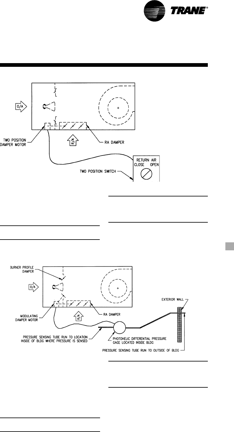
37MUA-PRC001-EN
Options
Motorized Return Air Damper
Purpose
To provide a way for recirculating return
air.
Operation
A two position switch controls the return
air damper.
When the two position switch is in the
“RA” position, the RA damper opens.
Fifty percent of supply air is RA,
50 percent of supply air is OA.
RA damper can be set to allow from
0 percent to 50 percent return air by field
adjustment of the linkage rods. The gas
valve opening is restricted when the RA
damper is open.
Code requires that outside ventilation air
be provided to the space in the amount
of 4 cfm per 1 MBh of burner rated
input.
All units are provided with a means that
will allow the customer to interlock OA
fans when the amount of OA provided
by the unit is not sufficient to meet the
4 cfm per 1 MBh requirement.
When the two position switch is in the
“OA” position, the RA damper is closed,
and 100 percent of supply air
is OA.
Note: This option cannot be used with a
two speed fan motor.
Motorized 75/25 Damper
Purpose
To provide a way for recirculating return
air and letting building pressure control
the amount of air which is recirculated.
Operation
If building pressure is less than desired,
the RA damper modulates to a more
closed position and the interlocked
burner profile damper modulates to a
more open position. More OA is brought
into building.
If building pressure is greater than
desired, the RA damper modulates to a
more open position and the interlocked
burner profile damper modulates to a
more closed position. Less OA is brought
into building.
At no time will the unit provide less than
25 percent OA to the building.
In general terms, the minimum OA is
25 percent; however, there are
cases where it can be as high as
40-50 percent, depending upon unit size,
burner size, gas train type and
gas pressure.
Code requires that outside ventilation air
be provided to the space in the amount
of 4 cfm per 1 MBh of burner rated input.
All units are provided with a means that
will allow the customer to interlock OA
fans when the amount of OA provided
by the unit is not sufficient to meet the 4
cfm per 1 MBh requirement.
Note: This option cannot be used with a
two speed fan motor.
Note: This option can be used with
either the Motorized Inlet Damper
option or the Motorized Outlet Damper
option.
Option Includes:
• Return air damper
• Burner profile damper
• Linkage
• Modulating damper motor(s)
• Photohelic differential pressure gauge
Note: This option can be used with
either the Motorized Inlet Damper
option or the Motorized Outlet Damper
option.
Option Includes:
• Return air damper
• Two position damper motor
• Damper switch
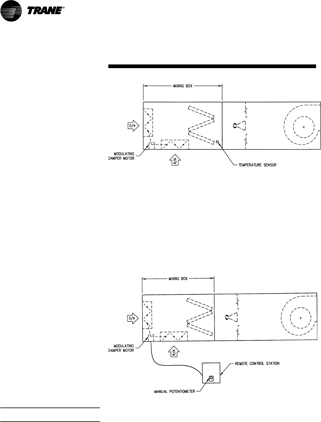
MUA-PRC001-EN38
Options
Mixing Box —
Temperature Control
Purpose
To provide a way for recirculating return
air and letting mixed air temperature
determine the amount of OA/RA.
Operation
A temperature sensor located after the V-
bank filter modulates the OA and RA
dampers to maintain a set temperature.
If temperature at sensor is cooler than
setting, OA damper modulates to a more
closed position, and RA damper
modulates to a more open position.
If temperature at sensor is warmer than
setting, OA damper modulates to a more
open position, and RA damper
modulates to a more closed position.
Mixing Box —
Manual Control
Purpose
To provide a way for recirculating return
air and using manual control to
determine the amount of OA/RA.
Operation
A manual potentiometer located at the
remote control station determines the
OA/RA setting. The minimum OA damper
position is factory set with a
potentiometer. The minimum OA
damper opening is set at 4 cfm per
1 MBh of burner rated input, or 25%
supply air, whichever is larger.
Option Includes:
• Mixing box with V-bank filter and
permanent filters
• Dampers
• Modulating damper motor(s)
• Manual potentiometer
Note: Remote control station not
included.
The minimum OA damper position is
factory set with a potentiometer. The
minimum OA damper position is set at 4
cfm per 1 MBh of burner rated input, or
25% supply air, whichever is larger.
The desired temperature at the
temperature sensor is set at the control
cabinet at the unit.
Option Includes:
• Mixing box with V-bank filter and
permanent filters
• Dampers
• Modulating damper motor(s)
• Temperature sensor
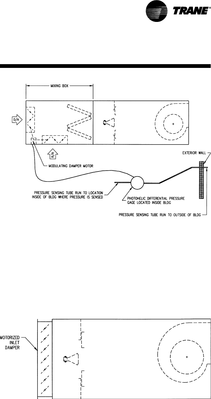
39MUA-PRC001-EN
Options
Mixing Box —
Building Pressure Control
Purpose
To provide a way for recirculating return
air and letting building pressure control
the amount of air which is recirculated.
Operation
If building pressure is less than desired,
the RA damper modulates to a more
closed position and the OA damper
modulates to a more open position.
More OA is brought into building.
If building pressure is greater than
desired, the RA damper modulates to a
more open position and the OA damper
modulates to a more closed position.
Less OA is brought into building.
The minimum OA damper position is
factory set with a potentiometer. The
minimum OA damper position is set at 4
cfm per 1 MBh of burner rated input, or
25% supply air, whichever is larger.
The desired pressure differential is set at
the photohelic.
Motorized Inlet Damper
Purpose
To provide a shut-off damper.
Operation:
When the fan switch is on, the inlet
damper begins to open. As the inlet
damper approaches the full open
position, a built-in end switch located
inside the damper motor closes. The
closed end switch starts the fan motor.
When the fan switch is turned to the
“off” position, or if there is a power
failure, the inlet damper closes.
Option Includes:
• Damper
• Two position damper motors with built-
in end switch and spring return
• Linkage
Option Includes:
• Mixing box with V-bank filter and
permanent filters
• Dampers
• Modulating damper motor(s)
• Photohelic differential pressure gauge
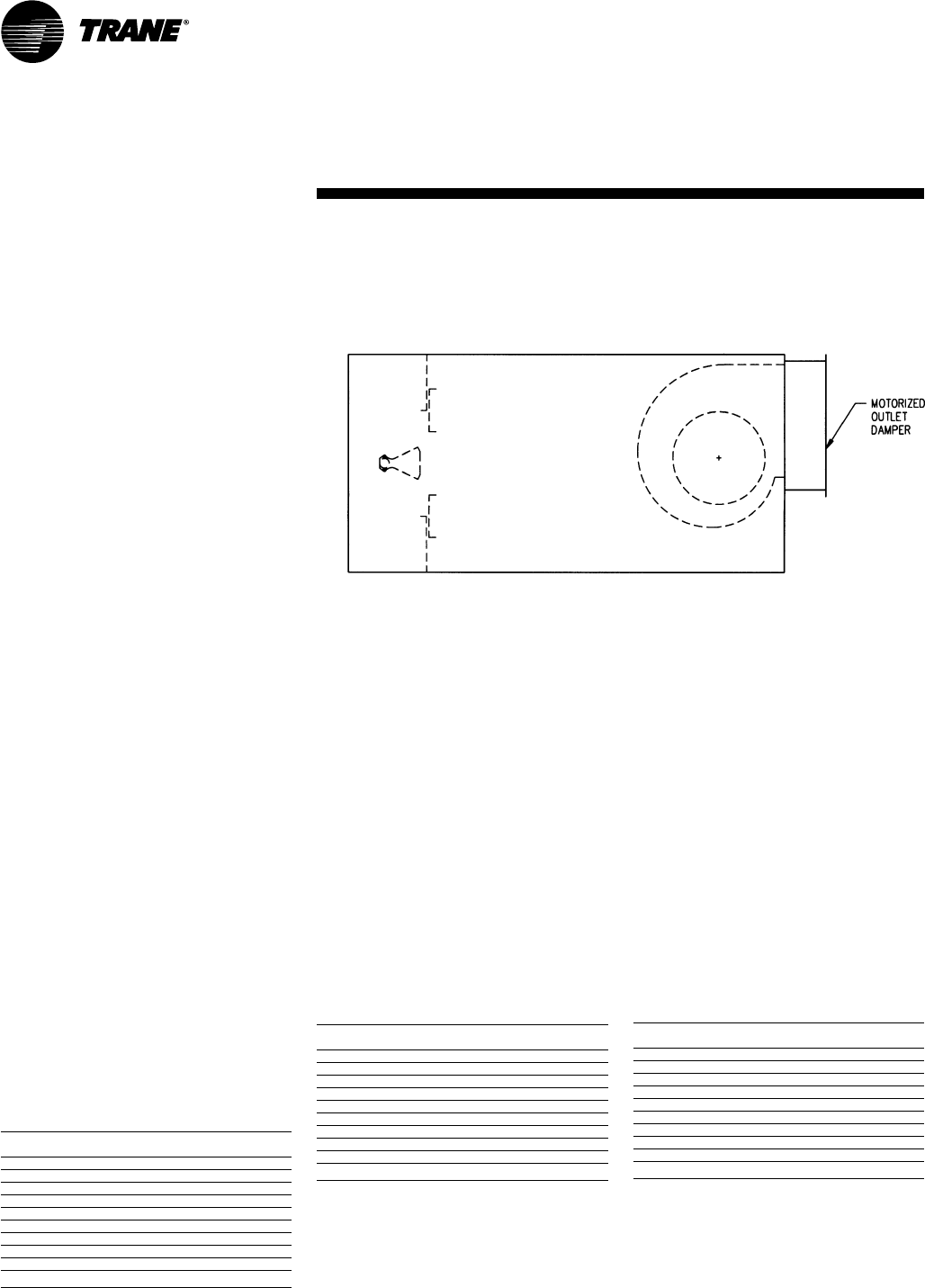
MUA-PRC001-EN40
Options
ETL Labeling Requirements
A DFOA unit with no mixing box,
motorized RA damper, or motorized
75/25 damper can bear the ETL label if:
1
The unit SCFM is less than the
Maximum SCFM given below.
2
The unit input is less than the Maximum
BTUH rating given below.
3
The unit temperature rise is less than the
Maximum Temperature Rise given
below.
4
The fuel is natural gas.
5
The motor is a single speed motor.
6
Unit components are standard (there are
exceptions to this).
ETL Labeling Requirements
A DFOA unit with a mixing box,
motorized RA damper, or motorized
75/25 damper can bear the ETL label if:
1
The unit SCFM is less than the
Maximum SCFM given below.
2
The unit input is less than the Maximum
BTUH rating given below.
3
The unit temperature rise is less than the
Maximum Temperature Rise given
below.
4
The fuel is natural gas.
5
The motor is a single speed motor.
6
Unit components are standard (there are
exceptions to this).
Model Max. Max. Max. Temp.
No. SCFM BTUH Rise
DFOA 109 3,000 291,262 100 F
DFOA 112 4,250 412,621 100 F
DFOA 115 6,000 582,524 100 F
DFOA 118 8,500 680,000 100 F
DFOA 215 12,000 1,349,831 100 F
DFOA 218 18,000 1,800,000 100 F
DFOA 220 26,000 2,924,634 100 F
DFOA 222 31,000 3,100,000 100 F
DFOA 225 46,000 5,174,353 100 F
DFOA 230 64,000 6,400,000 100 F
Model Max. Max. Max. Temp.
No. SCFM BTUH Rise
DFOA 109 3,000 424,565 120 F
DFOA 112 4,250 601,290 120 F
DFOA 115 6,000 848,880 120 F
DFOA 118 8,500 1,202,580 120 F
DFOA 215 12,000 1,697,760 120 F
DFOA 218 18,000 2,546,640 120 F
DFOA 220 26,000 3,678,480 120 F
DFOA 222 31,000 4,385,880 120 F
DFOA 225 46,000 6,508,080 120 F
DFOA 230 64,000 9,054,720 120 F
These requirements were current when this catalog was
printed.
Please contact Technical Support for the most current
data available.
CGA Approval Requirements
A DFOA unit with no mixing box,
motorized RA damper, or motorized 75/
25 damper can bear the CGA label if:
1
The unit SCFM is less than the Maximum
SCFM given below.
2
The unit input is less than the Maximum
Input BTUH given below.
3
The static pressure is in the range given
below.
4
Unit discharge temperature is 75 F
maximum.
5
The ambient temperature is minus 40 F
or greater.
6
The unit has a maximum temperature
rise of 90 F for single blower units and
100 F for double blower units.
7
The unit minimum input rating is 1/25 of
the Max. Input BTUH given below.
8
The fuel is natural gas.
9
The motor is a single speed motor.
10
Unit components are standard (there are
exceptions to this).
Model Static Max. Max. Input.
No. (in W.C.) SCFM (BTUH)
DFOA 109 0-4.0 3,000 325,500
DFOA 112 0-4.0 4,250 461,125
DFOA 115 0-4.0 6,000 851,000
DFOA 118 0-4.0 8,500 922,250
DFOA 215 0-4.0 12,000 1,302,000
DFOA 218 0-4.0 17,000 1,844,500
DFOA 220 0-4.0 26,000 2,821,000
DFOA 222 0-4.0 31,000 3,363,500
DFOA 225 0-4.0 46,000 4,991,000
DFOA 230 0-3.5 64,000 6,944,000
Motorized Outlet Damper
Purpose
To provide a shut-off damper.
Operation
When the fan switch is on, the outlet
damper begins to open. As the outlet
damper approaches the full open
position, a built-in end switch located
inside the damper motor closes. The
closed end switch starts the fan motor.
When the fan switch is turned to the
“off” position, or if there is a power
failure, the outlet damper closes.
Option Includes:
• Damper
• Two position damper motor with built-
in end switch and spring return
• Linkage

41MUA-PRC001-EN
Options
Exhaust Interlock
The exhaust interlock is a pair of contacts
on the unit that will close when the unit
is “on.” The customer can wire the
exhaust fan to the contacts so that when
the heating unit is “on,” the exhaust fan
will also be “on.” Note the heating unit
turns on the exhaust fan.
The auxiliary contacts on the fan motor
starter are the contacts which are used
as the exhaust interlock. The auxiliary
contacts are wired to the numbered
terminal strip. The customer can wire the
indicated terminals into the control
circuit of the exhaust fan.
Note: If the customer wants the exhaust
fan to turn the heating unit “on,” he/she
has to provide a pair of contacts that will
close when the exhaust fan is “on.”
Interlocking Relay
The interlocking relay is two pair of
contacts, one normally open and the
other normally closed. The contacts
switch positions when the unit is “on.”
The contacts are wired to the numbered
terminal strip. The customer can wire a
wide range of devices to the interlocking
relay by wiring to the indicated
terminals.
Seven Day Timeclock/
Night Setback Thermostat
The seven day timeclock is used
primarily for either one of the following:
1
Start and stop the unit at preset times
Example: A building is occupied at
8:00 AM. At 4:30 PM, people leave the
building. The timeclock could be set to
turn the unit on at 7:30 AM and off at
5:00 PM.
2
The timeclock can be used with an on-off
night setback thermostat (NSB
thermostat). The timeclock and NSB
thermostat would be wired so that
during the night, the NSB thermostat
would turn the unit on and off.
Example: Same as example above, only
at 5:00 PM the NSB thermostat would
turn the unit on and off. If the
temperature in the space fell below the
setting of the NSB thermostat, the unit
would come “on.” If the temperature
rose above the setting, the unit would go
“off.”
Inlet On-Off Duct Stat
Automatically turns burner off when inlet
air temperature equals setting of control.
Works as a lockout for the burner.
Example: If we want the burner to be
“off” if the entering air temperature is
65 degrees, the inlet on-off duct stat
would be set at 65 degrees.
Without the inlet on-off duct stat, if the
fan switch and heat switch are both “on,”
no matter how warm the incoming air,
the burner will go as low as low fire, but
will not go “off.”
UV Flame Sensor (UV Mini-Peeper)
Flame sensor checks to make sure the
pilot flame has ignited before gas is sent
to the main burner. Operates by sensing
the light of the pilot flame.
If the flame sensor does not sense the
pilot flame, the unit shuts down (fan and
burner go off) and the flame failure light
on the optional remote panel
goes on.
The unit has to be reset by pushing the
reset button on the burner relay.
Differences between UV Flame Sensor
and Flame Rod:
Both are used for the same purpose —
to check if the pilot flame is on. The
flame rod is “standard.” The UV sensor
needs to be ordered as an option.
If condensation forms on the flame rod
while the unit is off, it may give a false
signal and prevent the unit from coming
on. The wet flame rod does not sense
the pilot flame and shuts the unit down.
This nuisance tripping can be avoided
with the UV flame sensor.
Optional Gas Controls
Series 14 — Constant Discharge
Temperature
The constant discharge temperature, gas
modulating control system consists of
the Maxitrol electronic gas modulating
system (55 to 90 F range), which includes
a discharge air sensor located in the
blower discharge, a modulator/regulator
valve mounted in the gas piping
manifold, an amplifier installed in the
electrical control panel, a 115 to 24 volt
transformer, and a remote temperature
selector.
Series 44 — Space Temperature Control
The space temperature control, gas
modulating control system consists of
the Maxitrol electronic gas modulating
system, which includes a Series 44
discharge air sensor (55 to 90 F range)
mounted in the blower discharge, a
modulator regulator valve mounted in
the gas piping manifold, an amplifier
installed in the electric control panel, a
115 to 24 volt transformer, and a
Selectrastat mounted in the area where
the temperature is to be sensed.
MUA-PRC001-EN42
Options
Factory Installed Options
Motors — General
All motors are provided as standard,
with a starter for external overload
protection, a control transformer, and a
fusible disconnect switch.
Open Drip-Proof Motor
60 Hz/1800 Rpm
Single Phase
Optional 115V motors are available in ¾
to 3 hp models. Optional 208V motors
are available in ¾ to 7½ hp models.
Optional 230V motors are available in ¾
to 10 hp models. All motors have rigid
base construction and ball bearings.
Class A insulation is on all motors up to
and including 3 hp models. Class B
insulation is on 5 hp and above models.
Three-Phase
Optional 208, 230, 460V available in 1 to
60 hp models. All models have rigid
base construction and ball bearings.
Class B insulation is on all three-phase
motors.
Energy Efficient ODP
60 Hz/1800 Rpm
Three-Phase Only
Optional 208V motors are available in 1
to 30 hp models. 230 and 460V motors
are available in 1 to 60 hp models. All
motors have rigid base construction and
ball bearings. Class B insulation is on all
motors.
Totally Enclosed Motor
60 Hz/1800 Rpm
Three-Phase Only
Optional 208V motors are available in ¾
to 20 hp models. Optional 230 and 460V
motors are available in ¾ to 60 hp
models. All motors have rigid base
construction and ball bearings.
Energy Efficient TEFC
60 Hz/1800 Rpm
Three-Phase Only
Optional 208V motors are available in 1
to 30 hp models. 230 and 460V motors
are available in 1 to 60 hp models. All
motors have rigid base construction and
ball bearings. Class B insulation is on all
motors.
Two-Speed/One Winding Motors
60 Hz/1800/900 Rpm
Three-Phase Only
Optional 208 and 230V motors available
on 1 to 20 hp models. Optional 460V
motors are available on 1 to 50 hp
models. All motors have rigid base
construction and ball bearings. Class B
insulation is on all motors.
Two-Speed/Two Winding Motors
60 Hz/1800/1200 Rpm
Three-Phase Only
Optional 208 and 230V motors available
on 1 to 20 hp models. Optional 460V
motors are available on 1 to 50 hp
models. All motors have rigid base
construction and ball bearings. Class B
insulation is on all motors.
Additional Options*
Inlet Hood and Birdscreen
Hood constructed of 18-gauge
galvanized steel. Birdscreen is 18-gauge
galvanized steel with one-inch square
openings.
V-Bank Filter Section
Not required when a mixing box is
specified. Constructed of 18-gauge
galvanized steel.
Dampers and Mixing Box
Motorized Return Air Damper
This option provides a way to recirculate
air, with the return air opening
downstream of the burner. This option
includes return air damper, a two-
position damper motor, linkage and
damper switch. It is not available with
two-speed motors.
Motorized 75/25 Damper
This option provides a way for
recirculating return air and allows
building pressure to control the amount
of air that is recirculated. This option
includes a return air damper, burner
profile plate damper, damper linkage,
and modulating pressure controller. It is
not available with two-speed motors.
Mixing Box — Temperature Control
This option provides a way for
recirculating return air and allows mixed
air temperature to determine the amount
of OA/RA. This option includes mixing
box with filter section, dampers, damper
actuator(s), and damper controls.
Mixing Box — Building Pressure Control
This option provides a way for
recirculating return air and allows
building pressure to control the amount
of air which is recirculated. This option
includes a mixing box with filter section,
dampers, damper actuator(s), and
damper controls (including a photohelic
differential pressure gauge).
Mixing Box — Manual Control
This option provides a way for
recirculating return air and using manual
control to determine the amount of OA/
RA. This option includes a mixing box
with filter section, dampers, damper
actuator(s), and a manual
potentiometer.
Inlet/Outlet Dampers
Motorized Inlet Damper
This option provides a shutoff damper.
This option includes an outside air
damper, damper motor with built-in end
switch, and linkage. It is not available
with a mixing box.
Motorized Outlet Damper
This option provides a shutoff damper.
This option includes a discharge damper,
two-position damper motor with a built-
in end switch, and linkage.
*Based on unit design, some options
can ship factory installed or field
installed. Contact the factory for
verification.

43MUA-PRC001-EN
Accessories
Additional Factory Installed
Options
High Gas Pressure Regulator
1-5 Psig
Units 825 MBh and less require an
additional gas pressure regulator if inlet
pressure exceeds 1 psig. Inlet pressure at
the job must be specified.
5-10 Psig
An additional regulator is furnished. Inlet
pressure at the job must be specified.
Insulation
One-inch, 1½ lb. fiberglass insulation pin
spotted to casing.
Insulation on Basic Frame
Insulation on Filter Section
Internal Blower/Motor Isolation
This option includes a steel frame for
blower(s) and a fan motor with spring
type vibration isolators. It is not available
on vertical units.
Extended Grease Lines
This option allows lubrication of fan
bearings from the control side of the unit.
Controls Opposite from Standard
Inlet On-Off Duct Stat
This automatically turns the burner off
when inlet air temperature equals
desired discharge air temperature. It
works as a lockout for the burner.
Temperature range of 25 to 225 SPDT.
115V Duplex Receptacle
This option includes a transformer and
disconnect switch for the receptacle.
Components are mounted in the gas
piping manifold.
Circuit Analyzer
Provides indicator lights for maintenance
troubleshooting. If the unit is not
functioning properly, the service person
will want to know which circuits are open
and which are closed. The circuit analyzer
will tell the service person, at a glance,
the status (open or closed) of the
different circuits. If an indicating light is
lit, the circuit is in its correct operating
mode. It mounts on the control panel of
the unit. The number of lights and
functions depends on the control options
of the unit.
UV Flame Sensor
The flame sensor checks to make sure
the pilot flame has ignited before gas is
sent to the main burner. It operates by
sensing the light of the pilot flame.
Clogged Filter Switch
This option includes a pressure sensing
switch which senses the pressure drop
across the filters. When the pressure
drop reaches the setpoint, the switch
trips and lights the clogged filter light.
It is not required when City of Chicago
controls are ordered.
Exhaust Fan Interlock
This option includes a pilot duty rated
normally open contact on the main
supply fan motor starter that will close
simultaneously with the starter (10 amp
contacts).
Interlocking Relay
This option is energized by an auxiliary
contact on the supply fan motor starter
that can be used for additional
equipment that may need to run when
the supply fan is running (12 amp
contacts).
City of Chicago Controls
This option includes an access door
interlock switch, an alarm horn with
silence switch, low temperature limit,
and a clogged filter switch.
Field Installed Accessories
Vibration Feet
Rubber-in-shear vibration isolators
cannot be ordered with a roof curb —
they ship unmounted.
Vibration Feet — Basic Frame
Vibration Feet — Filter Section
Vibration Feet — Mixing Box
Seven-Day Time Clock
This option includes a Paragon seven-
day general purpose time control with a
four-pole switch.
100 DBL Alarm Horn and Silencing
Switch
The alarm horn and silencing switch are
field-wired so that if the pilot flame does
not ignite, the alarm sounds. To silence
the alarm, the push button silencing
switch is pushed.
Remote Control Station
Option includes fan and heat switches,
burner on light, alarm light, and Maxitrol
Selector or Selectrastat.
On-Off Night Setback Thermostat
This option will shut unit off when space
temperature is above setpoint. This is a
115V thermostat with a temperature
range of 50 to 80 F. Option is normally
used together with the seven-day
timeclock option.
High Gas Pressure Regulator —
Over 10 Psig
Specify inlet pressure at the jobsite. This
is required for selection of the regulator.
Roof Curbs
Roof curbs are fabricated of 12-gauge
galvanized steel. Curb gasket is provided.
The 12-inch high roof curbs ship
disassembled.
Roof Curb For Basic Frame —
No return air
Roof Curb For Basic Frame —
With return air downstream of the
burner
Roof Curb For Basic Frame —
With mixing box option

Literature Order Number
File Number
Supersedes
Stocking Location
The Trane Company
An American Standard Company
www.trane.com
For more information contact your local
district office, or e-mail us at
comfort@trane.com
Since The Trane Company has a policy of continuous product and product data improvement, it reserves the
right to change design and specifications without notice.
MUA-PRC001-EN
PL-UN-MUA-DFOA-PRC001-9-00
MUA-D-2 12/97
Inland - LaCrosse
