Troybilt 23aaba6x711 User Manual 1eee66b3 7183 4d21 8c25 B85c7d842705
User Manual: troybilt 23aaba6x711 Troy-Bilt Snow Blower 23AABA6X711 User Guide |
Open the PDF directly: View PDF ![]() .
.
Page Count: 40
TROY-BILT LLC, P.O. BOX 361131 CLEVELAND, OHIO 44136-0019
Printed In USA
OperatOr’s Manual
Safe Operation Practices • Set-Up • Operation • Maintenance • Service • Troubleshooting • Warranty
WARNING
READ AND FOLLOW ALL SAFETY RULES AND INSTRUCTIONS IN THIS MANUAL
BEFORE ATTEMPTING TO OPERATE THIS MACHINE.
FAILURE TO COMPLY WITH THESE INSTRUCTIONS MAY RESULT IN PERSONAL INJURY.
FLEX™ Snow Thrower Attachment — 23AABA6X711
Form No. 769-10250
(January 15, 2015)

Customer Support
Please do NOT return the machine to the retailer or dealer without first contacting the Customer Support Department.
If you have difficulty assembling this product or have any questions regarding the controls, operation, or maintenance of
this machine, you can seek help from the experts. Choose from the options below:
◊ Visit us on the web at www.troybilt.com
See How-to Maintenance and Parts Installation Videos at www.troybilt.com/tutorials
◊ Call a Customer Support Representative at (800) 828-5500 or (330) 558-7220
◊ Write to Troy-Bilt LLC • P.O. Box 361131 • Cleveland, OH • 44136-0019
Thank you for purchasing the Troy-Bilt FLEX™ Snow Thrower
Attachment. It was carefully engineered to provide excellent
performance when properly operated and maintained.
Please read this entire manual prior to operating the equipment.
It instructs you how to safely and easily set up, operate and
maintain your machine. Please be sure that you, and any other
persons who will operate the machine, carefully follow the
recommended safety practices at all times. Failure to do so could
result in personal injury or property damage.
All information in this manual is relative to the most recent
product information available at the time of printing. Review this
manual frequently to familiarize yourself with the machine, its
features and operation.
Please be aware that this Operator’s Manual may cover a range
of product specifications for various models. Characteristics and
features discussed and/or illustrated in this manual may not be
applicable to all models. We reserve the right to change product
specifications, designs and equipment without notice and
without incurring obligation.
If you have any problems or questions concerning the machine,
phone an authorized Troy-Bilt service dealer or contact us
directly. Troy-Bilt’s Customer Support telephone numbers,
website address and mailing address can be found on this page.
We want to ensure your complete satisfaction at all times.
Throughout this manual, all references to right and left side of the
machine are observed from the operating position
Thank You
Record Product Information
Before setting up and operating your new equipment, please
locate the model plate on the equipment and record the
information in the provided area to the right. You can locate
the model plate by looking at the rear mounting plate of the
snow thrower attachment WITHOUT the base unit attached. This
information will be necessary, should you seek technical support
via our web site, Customer Support Department, or with a local
authorized service dealer.
Model NuMber
Serial NuMber
To The Owner 1
2
Safe Operation Practices ........................................ 3
Assembly & Set-Up .................................................. 7
Controls ...................................................................10
Operation ................................................................ 11
Maintenence & Adjustments .................................13
Service .....................................................................15
Troubleshooting .....................................................17
Replacement Parts .................................................18
Warranty ................................................................ 22
Spanish ................................................................... 23
Table of Contents
Important Safe Operation Practices 2
3
Training
1. Read, understand, and follow all instructions on the
machine and in the manual(s) before attempting to
assemble and operate. Keep this manual in a safe place for
future and regular reference and for ordering replacement
parts.
2. Be familiar with all controls and their proper operation.
Know how to stop the machine and disengage them
quickly.
3. Never allow children under 14 years of age to operate this
machine. Children 14 and over should read and understand
the instructions and safe operation practices in this manual
and on the machine and be trained and supervised by an
adult.
4. Never allow adults to operate this machine without proper
instruction.
5. Thrown objects can cause serious personal injury. Plan
your snow-throwing pattern to avoid discharge of material
toward roads, bystanders and the like.
6. Keep bystanders, pets and children at least 75 feet from the
machine while it is in operation. Stop machine if anyone
enters the area.
7. Exercise caution to avoid slipping or falling, especially
when operating in reverse.
Preparation
Thoroughly inspect the area where the equipment is to be used.
Remove all doormats, newspapers, sleds, boards, wires and other
foreign objects, which could be tripped over or thrown by the
auger/impeller.
1. Always wear safety glasses or eye shields during operation
and while performing an adjustment or repair to protect
your eyes. Thrown objects which ricochet can cause serious
injury to the eyes.
2. Do not operate without wearing adequate winter outer
garments. Do not wear jewelry, long scarves or other loose
clothing, which could become entangled in moving parts.
Wear footwear which will improve footing on slippery
surfaces.
3. Use a grounded three-wire extension cord and receptacle
for all machines with electric start engines.
4. Adjust auger housing height to clear gravel or crushed rock
surfaces.
5. Disengage all control levers before starting the engine.
6. Never attempt to make any adjustments while engine is
running, except where specifically recommended in the
operator’s manual.
7. Let engine and machine adjust to outdoor temperature
before starting to clear snow.
WARNING! This symbol points out important safety instructions which, if not followed,
could endanger the personal safety and/or property of yourself and others. Read and follow
all instructions in this manual before attempting to operate this machine. Failure to comply
with these instructions may result in personal injury.
When you see this symbol. HEED ITS WARNING!
DANGER: This machine was built to be operated according to the safe operation practices in
this manual. As with any type of power equipment, carelessness or error on the part of the
operator can result in serious injury. This machine is capable of amputating fingers, hands,
toes and feet and throwing foreign objects. Failure to observe the following safety
instructions could result in serious injury or death.
CALIFORNIA PROPOSITION 65
WARNING! Engine Exhaust, some of its constituents, and certain vehicle components
contain or emit chemicals known to State of California to cause cancer and birth defects
or other reproductive harm.

4Section 2 — important Safe operation practiceS
Safe Handling of Gasoline
To avoid personal injury or property damage use extreme care
in handling gasoline. Gasoline is extremely flammable and the
vapors are explosive. Serious personal injury can occur when
gasoline is spilled on yourself or your clothes which can ignite.
Wash your skin and change clothes immediately.
a. Use only an approved gasoline container.
b. Extinguish all cigarettes, cigars, pipes and other
sources of ignition.
c. Never fuel machine indoors.
d. Never remove gas cap or add fuel while the engine is
hot or running.
e. Allow engine to cool at least two minutes before
refueling.
f. Never over fill fuel tank. Fill tank to no more than ½
inch below bottom of filler neck to provide space for
fuel expansion.
g. Replace gasoline cap and tighten securely.
h. If gasoline is spilled, wipe it off the engine and
equipment. Move machine to another area. Wait 5
minutes before starting the engine.
i. Never store the machine or fuel container inside
where there is an open flame, spark or pilot light
(e.g. furnace, water heater, space heater, clothes
dryer etc.).
j. Allow machine to cool at least 5 minutes before
storing.
k. Never fill containers inside a vehicle or on a truck
or trailer bed with a plastic liner. Always place
containers on the ground away from your vehicle
before filling.
l. If possible, remove gas-powered equipment from
the truck or trailer and refuel it on the ground. If this
is not possible, then refuel such equipment on a
trailer with a portable container, rather than from a
gasoline dispenser nozzle.
m. Keep the nozzle in contact with the rim of the fuel
tank or container opening at all times until fueling is
complete. Do not use a nozzle lock-open device.
Operation
1. Do not put hands or feet near rotating parts, in the auger/
impeller housing or chute assembly. Contact with the
rotating parts can amputate hands and feet.
2. The auger/impeller control lever is a safety device. Never
bypass its operation. Doing so makes the machine unsafe
and may cause personal injury.
3. The control levers must operate easily in both directions
and automatically return to the disengaged position when
released.
4. Never operate with a missing or damaged chute assembly.
Keep all safety devices in place and working.
5. Never run an engine indoors or in a poorly ventilated area.
Engine exhaust contains carbon monoxide, an odorless
and deadly gas.
6. Do not operate machine while under the influence of
alcohol or drugs.
7. Muffler and engine become hot and can cause a burn. Do
not touch. Keep children away.
8. Exercise extreme caution when operating on or crossing
gravel surfaces. Stay alert for hidden hazards or traffic.
9. Exercise caution when changing direction and while
operating on slopes. Do not operate on steep slopes.
10. Plan your snow-throwing pattern to avoid discharge
towards windows, walls, cars etc. Thus, avoiding possible
property damage or personal injury caused by a ricochet.
11. Never direct discharge at children, bystanders and pets or
allow anyone in front of the machine.
12. Do not overload machine capacity by attempting to clear
snow at too fast of a rate.
13. Never operate this machine without good visibility or light.
Always be sure of your footing and keep a firm hold on the
handles. Walk, never run.
14. Disengage power to the auger/impeller when transporting
or not in use.
15. Never operate machine at high transport speeds on
slippery surfaces. Look down and behind and use care
when backing up.
16. If the machine should start to vibrate abnormally, stop
the engine, disconnect the spark plug wire and ground it
against the engine. Inspect thoroughly for damage. Repair
any damage before starting and operating.
17. Disengage all control levers and stop engine before you
leave the operating position (behind the handles). Wait
until the auger/impeller comes to a complete stop before
unclogging the chute assembly, making any adjustments,
or inspections.
18. Never put your hand in the discharge or collector openings.
Always use the clean-out tool provided to unclog the
discharge opening. Do not unclog chute assembly while
engine is running. Shut off engine and remain behind
handles until all moving parts have stopped before
unclogging.
19. Use only attachments and accessories approved by the
manufacturer (e.g. wheel weights, tire chains, cabs etc.).
20. When starting engine, pull cord slowly until resistance
is felt, then pull rapidly. Rapid retraction of starter cord
(kickback) will pull hand and arm toward engine faster than
you can let go. Broken bones, fractures, bruises or sprains
could result.
21. If situations occur which are not covered in this manual, use
care and good judgment. Contact Customer Support for
assistance and the name of your nearest servicing dealer.

5Section 2 — important Safe operation practiceS
Clearing a Clogged Discharge Chute
Hand contact with the rotating impeller inside the discharge
chute is the most common cause of injury associated with snow
throwers. Never use your hand to clean out the discharge chute.
To clear the chute:
1. SHUT THE ENGINE OFF!
2. Wait 10 seconds to be sure the impeller blades have
stopped rotating.
3. Always use a clean-out tool, not your hands.
Maintenance & Storage
1. Never tamper with safety devices. Check their proper
operation regularly. Refer to the maintenance and
adjustment sections of this manual.
2. Before cleaning, repairing, or inspecting machine
disengage all control levers and stop the engine. Wait until
the auger/impeller come to a complete stop. Disconnect
the spark plug wire and ground against the engine to
prevent unintended starting.
3. Check bolts and screws for proper tightness at frequent
intervals to keep the machine in safe working condition.
Also, visually inspect machine for any damage.
4. Do not change the engine governor setting or over-speed
the engine. The governor controls the maximum safe
operating speed of the engine.
5. Snow thrower shave plates and skid shoes are subject to
wear and damage. For your safety protection, frequently
check all components and replace with original equipment
manufacturer’s (OEM) parts only. “Use of parts which do
not meet the original equipment specifications may lead to
improper performance and compromise safety!”
6. Check control levers periodically to verify they engage
and disengage properly and adjust, if necessary. Refer
to the adjustment section in this operator’s manual for
instructions.
7. Maintain or replace safety and instruction labels, as
necessary.
8. Observe proper disposal laws and regulations for gas, oil,
etc. to protect the environment.
9. Prior to storing, run machine a few minutes to clear snow
from machine and prevent freeze up of auger/impeller.
10. Never store the machine or fuel container inside where
there is an open flame, spark or pilot light such as a water
heater, furnace, clothes dryer etc.
11. Always refer to the operator’s manual for proper
instructions on off-season storage.
12. Check fuel line, tank, cap, and fittings frequently for cracks
or leaks. Replace if necessary.
13. Do not crank engine with spark plug removed.
14. According to the Consumer Products Safety Commission
(CPSC) and the U.S. Environmental Protection Agency (EPA),
this product has an Average Useful Life of seven (7) years,
or 60 hours of operation. At the end of the Average Useful
Life have the machine inspected annually by an authorized
service dealer to ensure that all mechanical and safety
systems are working properly and not worn excessively.
Failure to do so can result in accidents, injuries or death.
Do not modify engine
To avoid serious injury or death, do not modify engine in any
way. Tampering with the governor setting can lead to a runaway
engine and cause it to operate at unsafe speeds. Never tamper
with factory setting of engine governor.
Notice Regarding Emissions
Engines which are certified to comply with California and federal
EPA emission regulations for SORE (Small Off Road Equipment)
are certified to operate on regular unleaded gasoline, and
may include the following emission control systems: Engine
Modification (EM), Oxidizing Catalyst (OC), Secondary Air
Injection (SAI) and Three Way Catalyst (TWC) if so equipped.
Spark Arrestor
WARNING! This machine is equipped with an
internal combustion engine and should not be used
on or near any unimproved forest-covered, brush
covered or grass-covered land unless the engine’s
exhaust system is equipped with a spark arrestor
meeting applicable local or state laws (if any).
If a spark arrestor is used, it should be maintained in effective
working order by the operator. In the State of California the
above is required by law (Section 4442 of the California Public
Resources Code). Other states may have similar laws. Federal laws
apply on federal lands.
A spark arrestor for the muffler is available through your
nearest engine authorized service dealer or contact the service
department, P.O. Box 361131 Cleveland, Ohio 44136-0019.
6Section 2 — important Safe operation practiceS
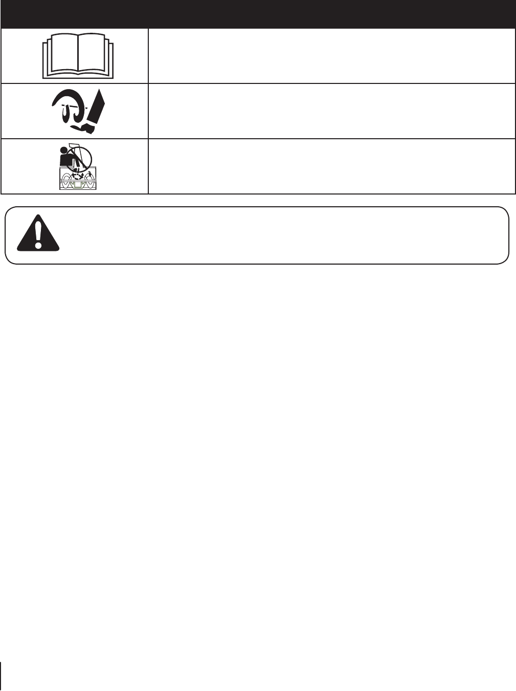
Safety Symbols
This page depicts and describes safety symbols that may appear on this product. Read, understand, and follow all instructions on the
machine before attempting to assemble and operate.
Symbol Description
READ THE OPERATOR’S MANUAL(S)
Read, understand, and follow all instructions in the manual(s) before attempting to
assemble and operate
WARNING— ROTATING AUGER
Avoid injury from rotating auger. Keep hands, feet, and clothing away.
WARNING— ROTATING BLADES
Keep hands out of inlet and discharge openings while machine is running. There are rotating
blades inside
WARNING! Your Responsibility—Restrict the use of this power machine to persons who read, understand and
follow the warnings and instructions in this manual and on the machine.
SAVE THESE INSTRUCTIONS!
Assembly & Set-Up 3
7
Assembly
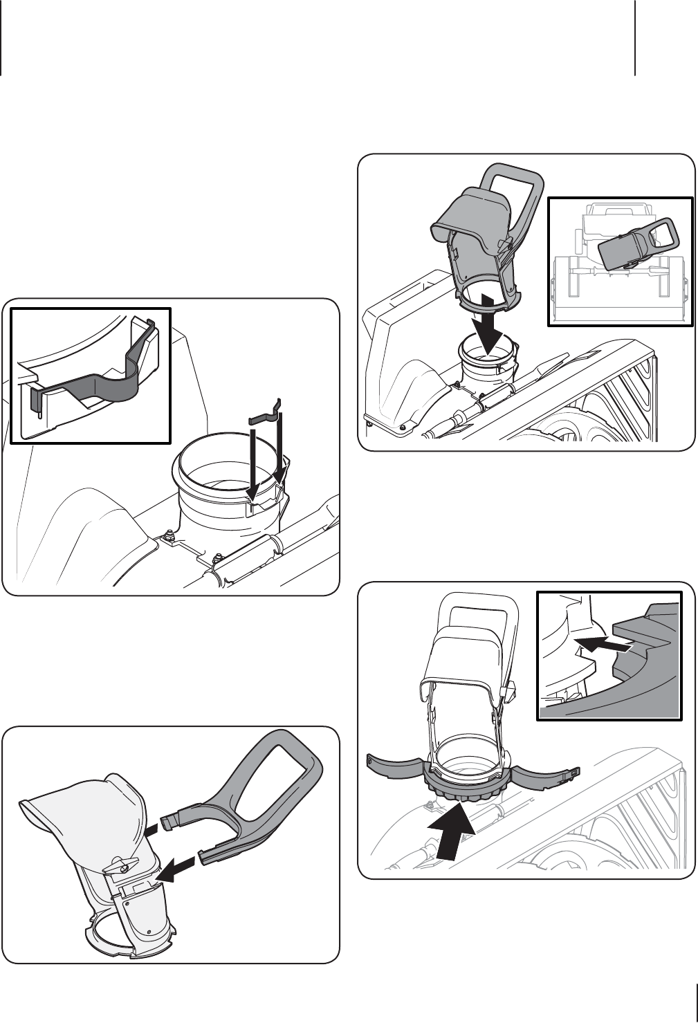
Installing the Discharge Chute
A discharge chute, wire spring, and chute band, have been
included with this attachment. Please assemble them now
by installing the discharge chute onto the snow thrower by
following these steps:
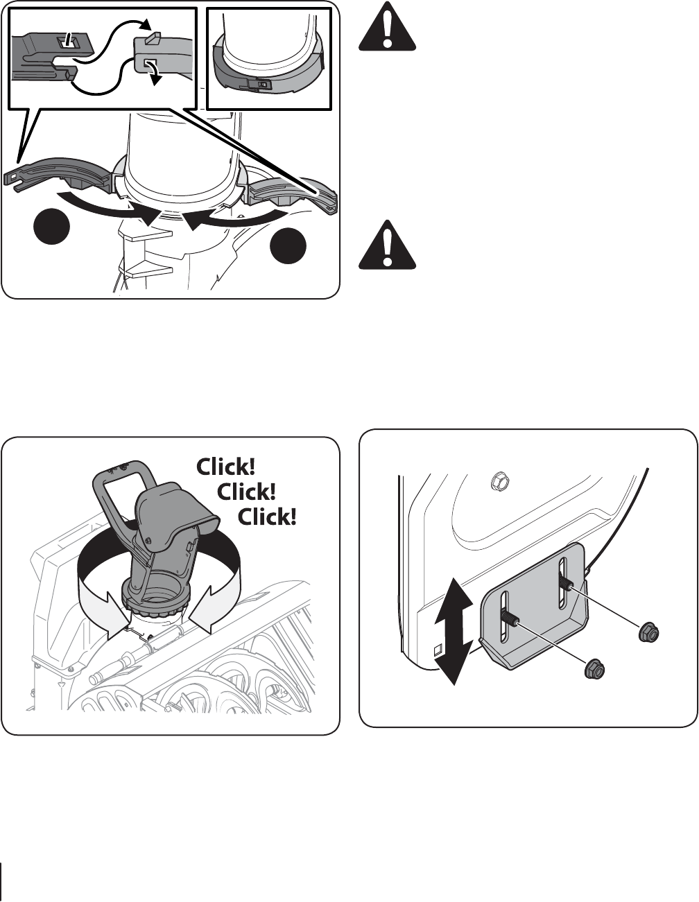
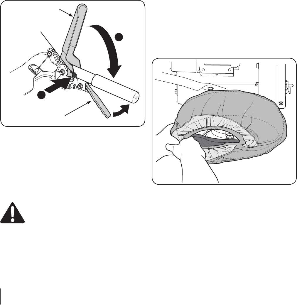
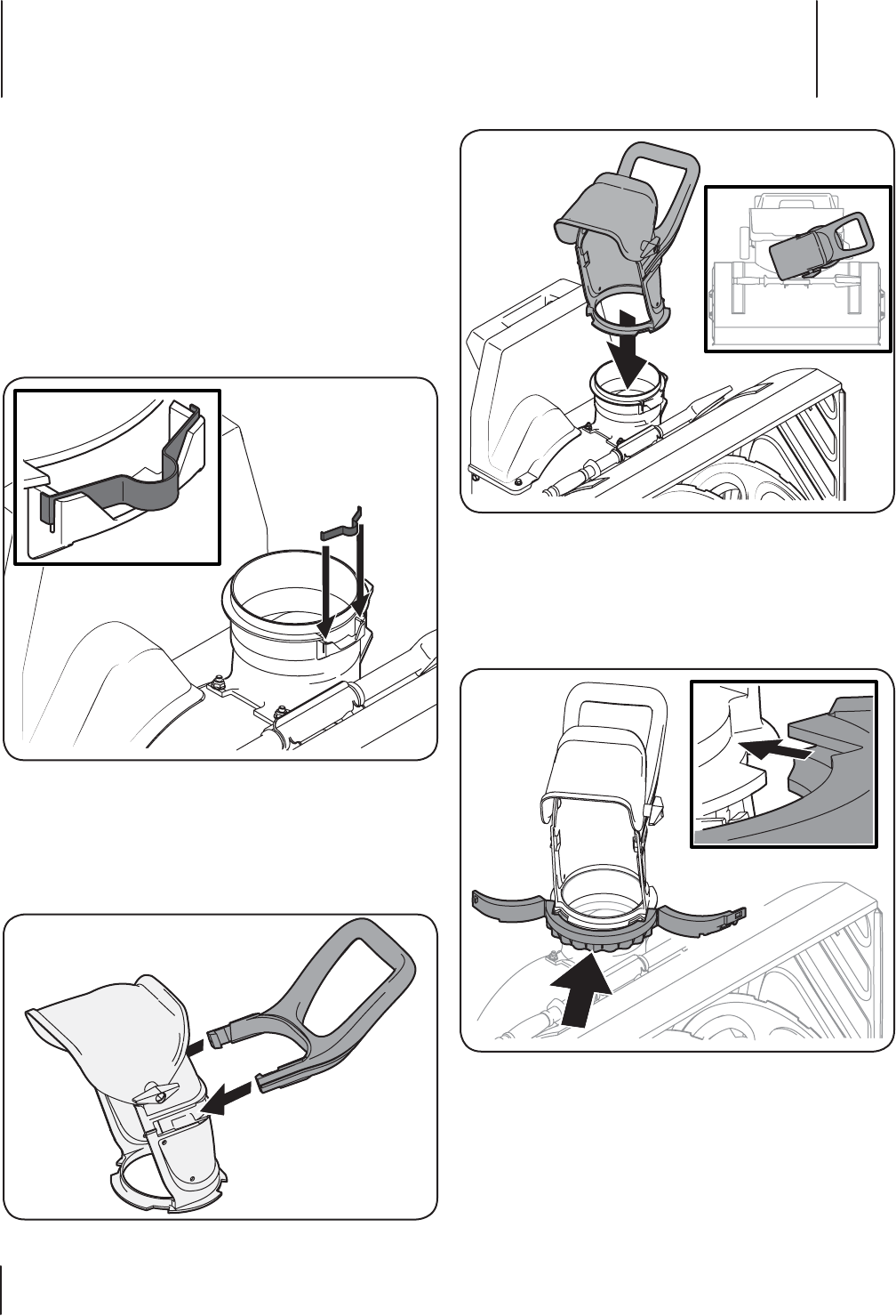
1. Install the wire spring into the discharge opening
of the snow thrower by inserting both ends into the
slots provided. See Figure 3-1 for proper location and
orientation of the spring. The inset of Figure 3-1 shows the
spring properly installed with the ends fitted into the slots
provided.
Figure 3-1
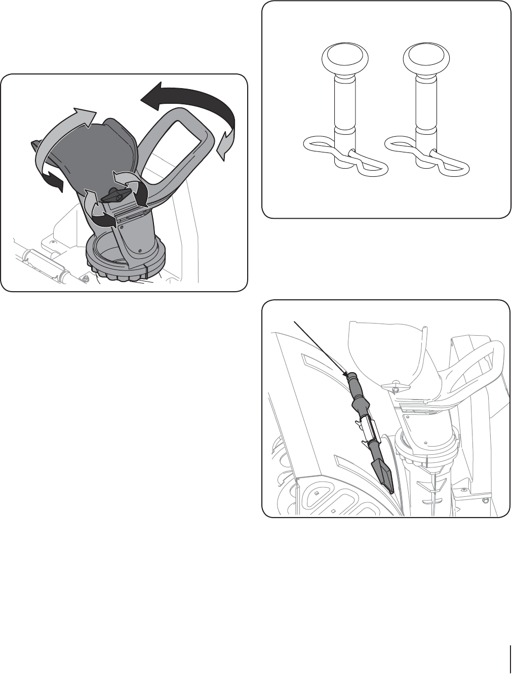
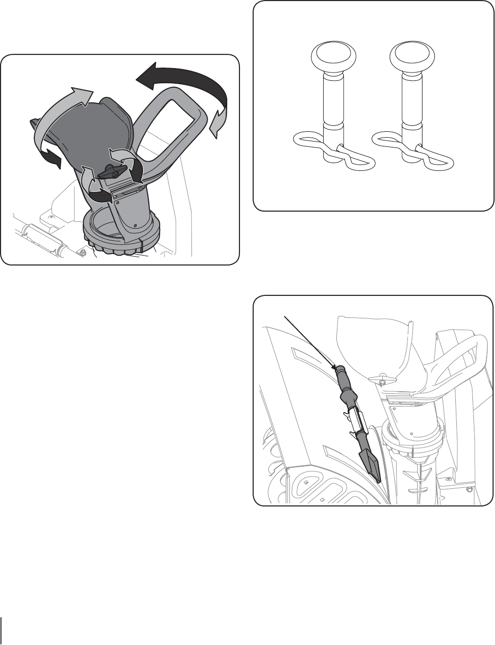
2. Install the discharge chute, packed loose in the carton,
onto the snow thrower attachment, as shown in Figure 3-3.
Note: Position the discharge chute at an angle to the right
for ease of installation.
3. Clip the discharge chute handle onto the discharge chute,
as shown in Figure 3-2.
Figure 3-2
Note: Place a dab of white lithium grease (included with
this attachment) onto the chute ring, chute spring, and
chute adapter ring prior to assembly.
Figure 3-3
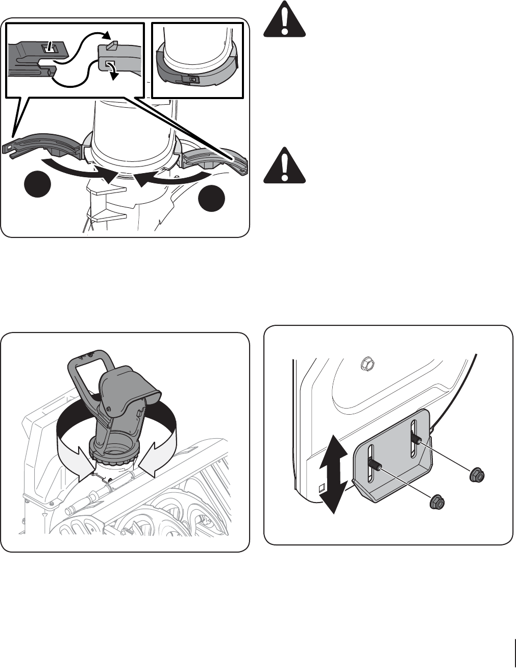
4. Install the chute band as shown in Figure 3-4. With the
discharge chute positioned to the right as shown, install
the chute band by lining up the notches in the front with
the band, and making certain to fit the discharge chute
inside the channel of the chute band, as detailed in the
inset of Figure 3-4.
Figure 3-4
8Section 3 — ASSembly & Set-Up
5. Secure the chute band to itself by first aligning the two
snap-fit features and pushing the two ends (1 & 2) together
as shown. Be sure both tabs on the two ends engage each
other, as shown in the top left inset of Figure 3-5. When
properly assembled, the chute band will appear as in the
top right inset of Figure 3-5.
1
2
Figure 3-5
IMPORTANT: If you need to remove the chute for any reason,
a screw driver must be used to release the locking tabs shown
above in the left inset of Figure 3-5.
Note: If the installation has been completed properly, a
click! click! click! sound will be heard when rotating the
chute to the left and right. See Figure 3-6.
Figure 3-6
Set-up
Adjust Skid Shoes
The snow thrower skid shoes are adjusted upward at the factory
for shipping purposes. Adjust them downward, if desired, prior to
operating the snow thrower attachment.
CAUTION : It is not recommended that you
operate this snow thrower attachment on gravel as
it can easily pick up and throw loose gravel, causing
personal injury or damage to the snow thrower and
surrounding property.
• For close snow removal on a smooth surface, raise skid
shoes higher on the auger housing.
• Use a middle or lower position when the area to be cleared
is uneven, such as a gravel driveway
NOTE: If you choose to operate the snow thrower on
a gravel surface, keep the skid shoes in position for
maximum clearance between the ground and the shave
plate.
CAUTION: Operating a snow thrower equipped
with steel skid shoes may result in damage to
natural stone paver surfaces (e.g. sandstone,
bluestone, limestone). Refer to the Replacement
Parts or Attachments & Accessories sections for
information on available polymer skid shoes.
To adjust the skid shoes:
1. Loosen the four hex nuts (two on each side) and carriage
bolts. Move skid shoes to desired position. See Figure 3-7.
2. Make certain the entire bottom surface of skid shoe is
against the ground to avoid uneven wear on the skid shoes.
3. Retighten nuts and bolts securely.
Figure 3-7
9Section 3 — ASSembly & Set-Up
Discharge Chute
The position of the upper discharge chute can be adjusted to
control the distance that the discharged snow will be thrown,
and the direction at which it will be discharged. Follow these
steps to adjust the discharge chute:
1. Loosen the wing knob on the upper chute, adjust the chute
to desired operating position.
2. Tighten the wing knob on the upper chute making sure
the carriage bolt on the inside of the discharge chute is
correctly positioned. Refer to Figure 3-8.
Figure 3-8
3. To adjust the direction that the snow will be thrown, use
the handle on the upper discharge chute to control the
direction of the discharged snow. Refer back to Figure 3-8.
Shear Pins
A pair of replacement auger shear pins and bow tie cotter pins
are included with this snow thrower attachment. See Figure 3-9.
Store them in a safe place until needed.
Figure 3-9
Chute Clean-Out Tool
The chute clean-out tool is fastened to the top of the auger
housing with a mounting clip and a cable tie at the factory. Cut
the cable tie before operating the snow thrower. See Figure 3-10.
Chute Clean-out Tool
Figure 3-10
Engine
Refer to the FLEX™ Base Unit Operator’s Manual for details
regarding all engine-related controls and features.
Drive Control Lever
This lever propels the entire machine forward.
Attachment Control Lever
Squeeze the auger control against the upper handle to engage
the augers; release to disengage the augers.
Auger
When engaged, the auger’s rotation draw snow into the auger
housing and throws it out the discharge chute.
Chute Assembly
Snow drawn into the auger housing is discharged out of the
chute assembly
Chute Handle
The direction of snow throwing corresponds to the direction
of the chute opening. Use the chute handle to turn the chute
assembly in the direction you wish to throw the snow.
Chute Knob
The distance snow is thrown can be adjusted by either raising
or lowering the upper chute. Loosen the chute knob on the side
of the upper chute to adjust. Pivot the upper chute to desired
position, and retighten the chute knob.
Shave Plate
The shave plate maintains contact with pavement as the snow
thrower is propelled, allowing snow close to pavement’s surface
to be discharged.
Skid Shoes
Position the skid shoes based on surface conditions. Adjust
upward for hard-packed snow. Adjust downward when
operating on gravel or crushed rock surfaces. See the Assembly &
Setup section for details on adjusting the skid shoes.
Chute Clean-Out Tool
The chute clean-out tool is conveniently fastened to the rear of
the auger housing with a mounting clip. It is used to dislodge
and scoop any snow and ice which has formed in and near the
chute assembly.
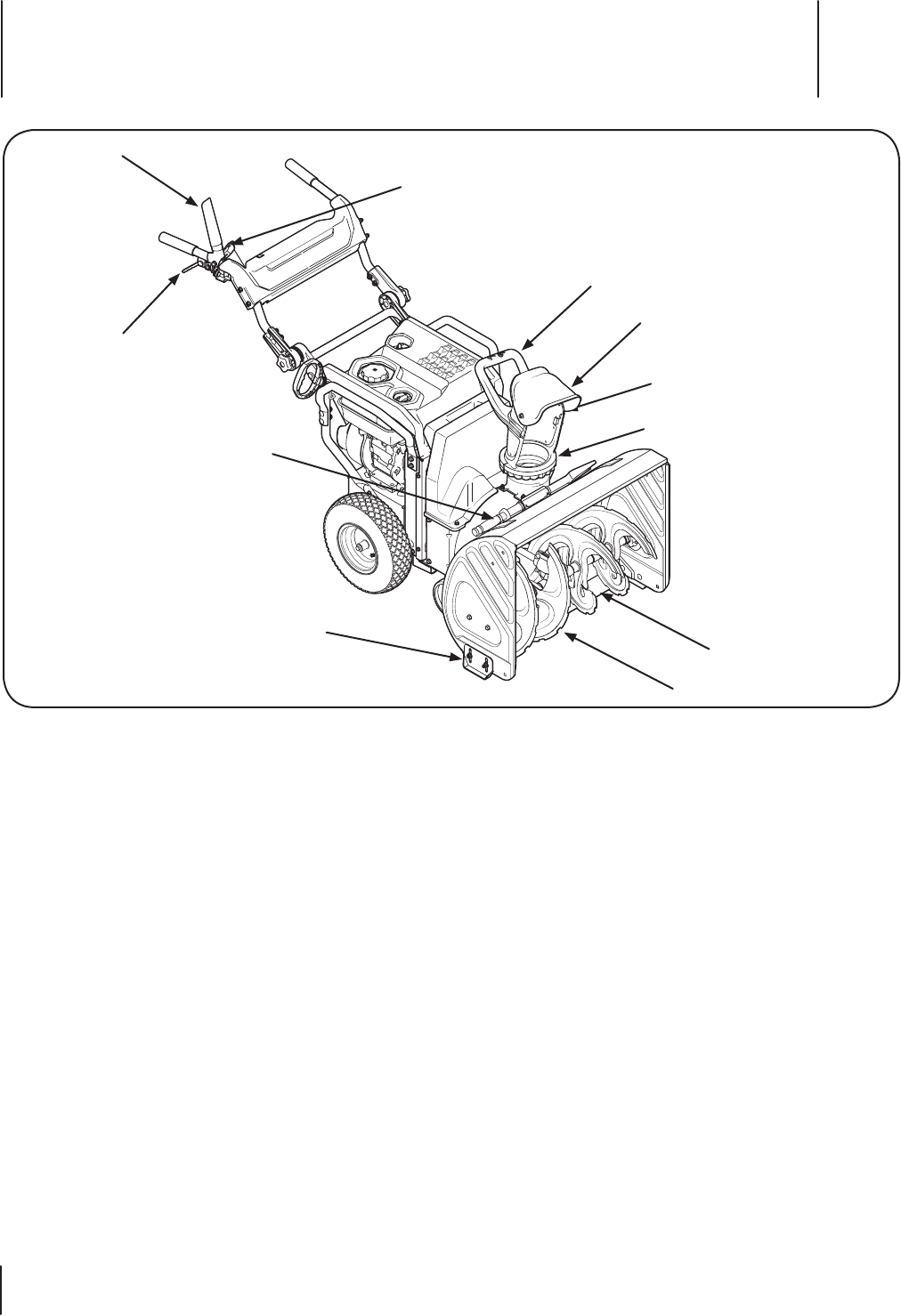
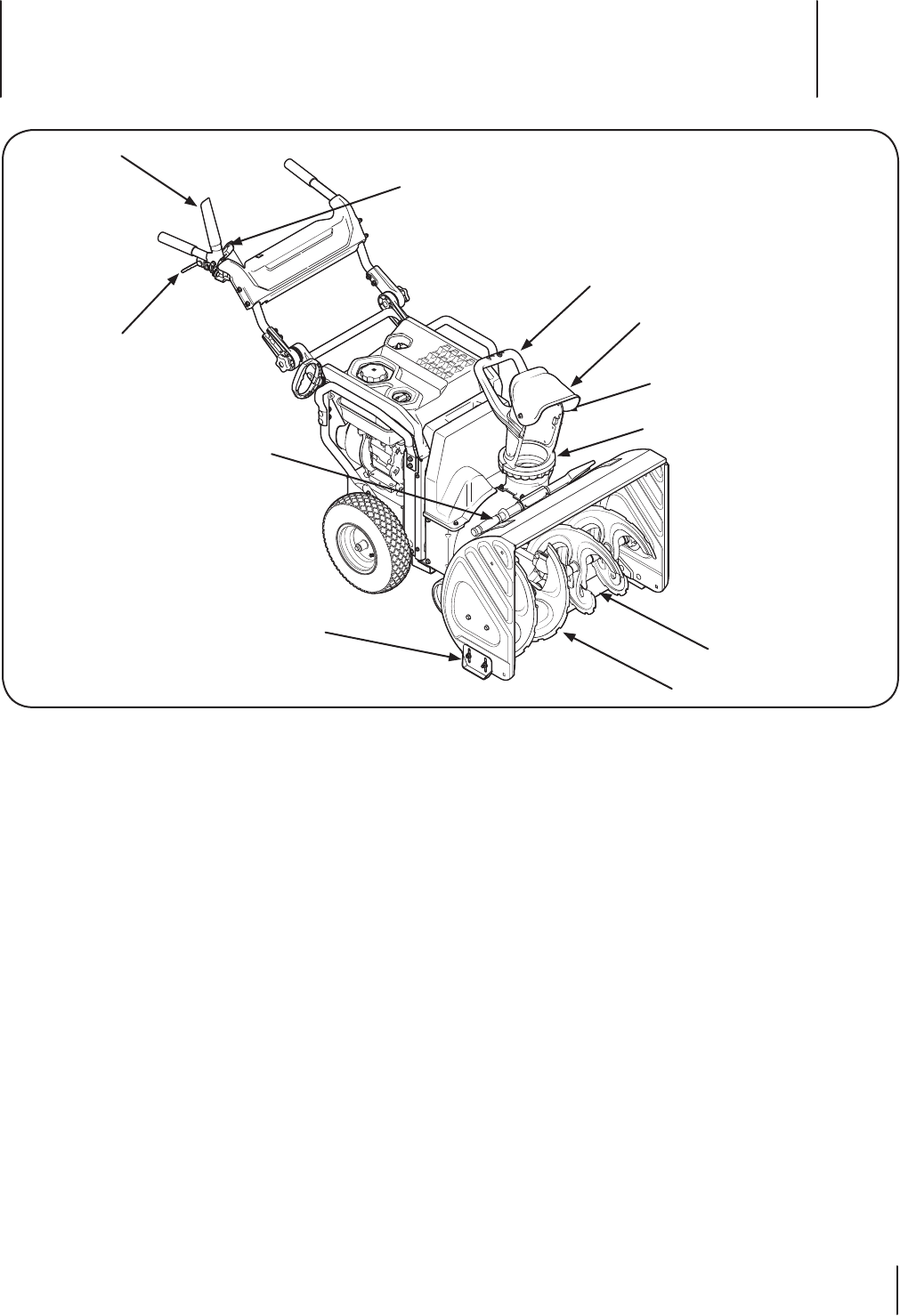
Chute Handle
Shave Plate
Auger
Upper Chute
Chute Knob
Skid Shoe
Chute Clean-out Tool
Drive Control Lever
Attachment Control Lever
Attachment Control Lever Lock
Chute Assembly
Figura 4-1
Controls and Features 4
10
Starting The Engine
Refer to the FLEX™ Power Base’s operator’s manual for engine
starting and operating instructions.
Couple Snow Thrower Attachment with Power
Base
1. With the kickstand UP on the FLEX™ Power Base, as shown
in Figure 5-1, roll it over to the snow thrower attachment.
Figure 5-1
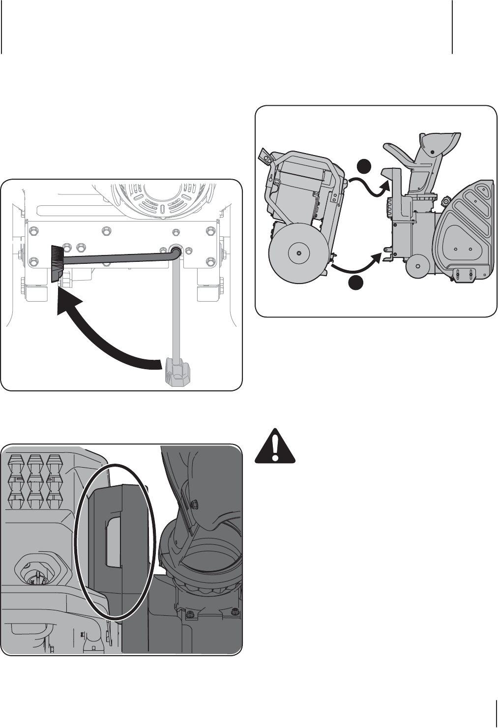
2. Tip the FLEX™ Power Base forward, engaging the top
mounting tab with the mounting handle on the snow
thrower attachment, see Figure 5-2.
Figure 5-2
3. Once the top mount is engaged (1), and with both hands
on the handle grips, tip the unit backwards somewhat
swiftly to engage the bottom mounts (2). See Figure 5-3.
1
2
Figure 5-3
Note: The operator will be able to hear the lower mounts
engage and lock when coupled properly.
To Uncouple the Snow Thrower Attachment from Power Base:
Fully stop the power unit engine before attempting to perform
any maintenance steps or uncoupling of the attachment. Never
attempt to uncouple the power base from the snow thrower
attachment WITH the engine running.
WARNING! Always turn off the FLEX™ Power Base
engine and remove the key prior to attempting to
replace the shear pins or uncoupling of the power
base from the attachment.
1. Put the kickstand down.
2. Tip the FLEX™ Power Base forward to disengage the
bottom mounts, then the top mount.
3. Move the FLEX™ Power Base away from the snow thrower
attachment.
Note: With the kickstand deployed in the downward
(unlocking) position, the FLEX™ Power Base will rest
comfortably in a parked position.
Operation 5
11
To Engage Drive
1. To engage the drive, squeeze the Drive Control Lever
completely up against the upper handle to engage the
wheels. To stop the forward motion, release the drive
control.
Note: This Drive Control Lever is a variable speed drive
control. Pulling the drive lever all the way in will give
the operator full speed, however full speed should not
be achieved for some operations, such as during snow
throwing.
To Engage Augers
1. To engage the augers, push in on the Attachment Control
Lever Safety Lock button (1 in Figure 5-4).
2. Squeeze the Attachment Control Lever completely against
the upper handle (2). To stop the augers, release handle.
1
2
Drive Control Lever
Attachment Control Lever
Attachment Control Lever
Safety Lock
Figure 5-4
Shear Pins
The augers are secured to the spiral shaft with four shear pins
and cotter pins. If the auger should strike a foreign object or ice
jam, the snow thrower is designed so that the pins may shear.
See the Service Section later in this manual for instructions on
replacing the shear pins.
Chute Clean-Out Tool
WARNING! Never use your hands to clear a
clogged chute assembly. Shut off engine and remain
behind handles until all moving parts have stopped
before unclogging.
The chute clean-out tool is conveniently fastened to the rear of
the auger housing with a mounting clip. Should snow and ice
become lodged in the chute assembly during operation, proceed
as follows to safely clean the chute assembly and chute opening:
1. Release both the Attachment Control Lever and the Drive
Control Lever.
2. Shut off engine as instructed in the engine manual.
3. Remove the clean-out tool from the clip which secures it to
the rear of the auger housing.
4. Use the shovel-shaped end of the clean-out tool to
dislodge and scoop any snow and ice which has formed in
and near the chute assembly.
5. Refasten the clean-out tool to the mounting clip on the
rear of the auger housing, start the snow thrower’s engine
as instructed in the engine manual.
While standing in the operator’s position (behind the snow
thrower), engage the Attachment Control Lever for a few seconds
to clear any remaining snow and ice from the chute assembly.
Installing the Snow Sock for Additional Traction
Two snow socks have been included with this snow thrower
attachment to provide additional traction when moving snow.
Follow these steps to install the snow socks:
1. Fit a snow sock over the top of the wheel on the FLEX™
Power Base, as shown in Figure 5-5, then work the rest of it
around the bottom of the wheel.
2. Repeat on the other side.
Note: Snow socks are designed for use during snow
removal only, and are not meant to be used with any other
FLEX attachments.
Figure 5-5
12 Section 5 — operation
Maintenance & Adjustments 6
13
Adjusting the Auger Drive Cable
After periods of extended use, and during the break-in period, it
may be necessary to adjust the auger drive cable. Follow these
simple steps to adjust the auger drive cable:
1. Uncouple the power base and the snow thrower
attachment from each other.
WARNING! Always turn off the FLEX™ Power Base
engine and remove the key prior to attempting to
uncouple of the power base from the attachment.
2. Remove the plastic belt cover on the snow thrower
attachment by removing the two self-tapping screws that
secure it. Refer back to Figure 6-1.
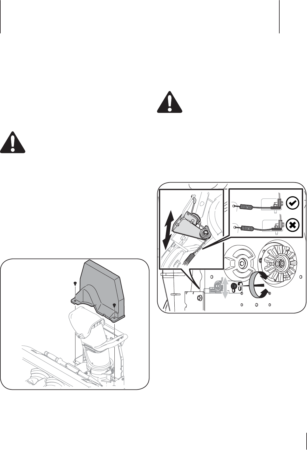
3. Looking at the rear mounting plate of the snow thrower
attachment, loosen (but do not remove) the left side hex
screw shown in Figure 6-2.
Note: The other screw (to the right of the hex screw
(previously loosened) is a shoulder bolt that does not need
to be loosened.
Figure 6-2
4. On the front side of the mounting plate, move the cable
tension guide up or down to remove any slack in the auger
drive cable. See the left inset of Figure 6-2.
Note: Be sure that the adjustment does not apply
any pressure on the cable and the actuator arm. This
adjustment is simply to remove the excess slack in the
auger cable as shown in the right handed inset of Figure
6-2.
5. Tighten the left hand side hex screw to complete this
adjustment.
Maintenance
General Recommendations
• Always observe safety rules when performing any type of
maintenance.
• The warranty on this snow thrower does not cover items
that have been subjected to operator abuse or negligence.
To receive full value from the warranty, operator must
maintain the snow thrower as instructed in this manual.
• Periodically check all fasteners and hardware to make sure
these are tight.
WARNING! Before servicing, repairing, lubricating,
or inspecting, disengage all controls and stop
engine. Wait until all moving parts have come to a
complete stop. Disconnect spark plug wire and
ground it against the engine to prevent unintended
starting. Always wear safety glasses during
operation or while performing any adjustments or
repairs.
Engine
IMPORTANT: Refer to the FLEX™ Power Base operator’s manual
for complete engine servicing instructions.
Check V-Belts
Follow instructions below to check condition of drive belts every
50 hours of operation.
1. Remove the plastic belt cover on the snow thrower
attachment by removing the two self-tapping screws that
secure it. See Figure 6-1.
Figure 6-1
2. Visually inspect for frayed, cracked, or excessively worn
out belt. Replace, if necessary, following instructions in the
Service section of this manual.
14 Section 6— Maintenance & adjuStMentS
Shave Plate and Skid Shoes
The shave plate and skid shoes on the bottom of the snow
thrower are subject to wear. These should be checked
periodically and replaced when necessary.
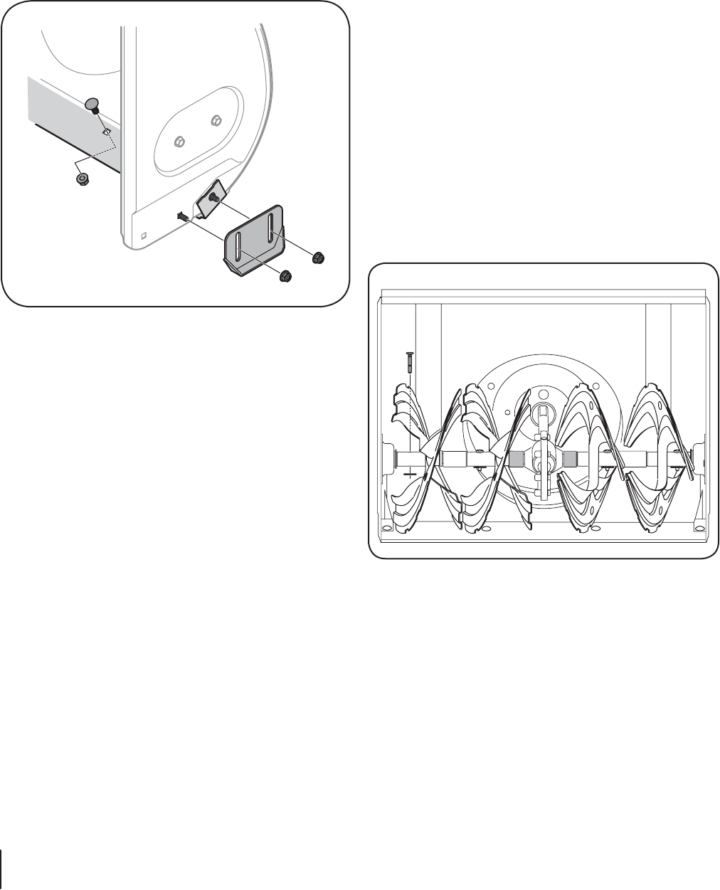
To replace skid shoes:
1. Remove the carriage bolts and nuts securing each skid shoe
to the auger housing, See Figure 6-3.
NOTE: Augers not shown for clarity.
Figure 6-3
2. Reassemble new skid shoes with hardware just removed.
Make sure the skid shoes are adjusted to be level.
3. Note: Refer to the Assembly & Set-Up section for
information regarding adjusting the skid shoes.
To remove shave plate:
1. Remove both skid shoes and hardware including carriage
bolts and nuts which attach shave plate to the snow
thrower housing. For location of shave plate, see Figure 6-3.
2. Reassemble new shave plate, making sure heads of the
carriage bolts are to the inside of the housing.
3. Reinstall skid shoes. Tighten securely.
Off-Season Storage
If the snow thrower attachment will not be used for 30 days
or longer, or if it is the end of the snow season when the last
possibility of snow is gone, the equipment needs to be stored
properly. Follow storage instructions below to ensure top
performance from the snow thrower for many more years.
1. Store the equipment in a clean, dry area.
2. If storing the snow thrower in an unventilated area,
rustproof the machine using a light oil or silicone to coat
the snow thrower.
3. Clean the exterior of the snow thrower.
Preparing The Engine
IMPORTANT: Refer to the FLEX™ Power Base operator’s manual
for complete engine servicing instructions.
Lubrication
Auger Shaft
At least once a season, remove the shear pins from the auger
shaft. Spray lubricant inside the shaft and around the spacers and
the flange bearings found at either end of the shaft.
See Figure 6-4.
Figure 6-4
Wheels
At least once a season, remove both wheels. Clean and coat the
axles with a multipurpose automotive grease before reinstalling
wheels.
Service 7
15
Augers
The augers are secured to the spiral shaft with four shear pins and
cotter pins. If you hit a foreign object or ice jam, the snow thrower
is designed so that the pins may shear.
If the augers do not turn, check if the pins have sheared. Replace,
if needed, with proper shear pins. Refer to Parts List for correct
part number.
CAUTION: NEVER replace the auger shear pins
with standard pins or fasteners. Any damage to the
auger gearbox or other components, as a result of
doing so, will NOT be covered by your snow
thrower’s warranty.
Replacing Shear Pins
CAUTION: NEVER replace the auger shear pins
with anything other than OEM Parts No. 738-04124A
replacement shear pins and 714-04040 bow-tie
cotter pins. Any damage to the auger gearbox or
other components as a result of failing to do so will
NOT be covered by your snow thrower attachment’s
warranty.
WARNING! Always turn off the snow thrower’s
engine, as instructed in the engine owner’s manual
and remove the key prior to replacing shear pins.
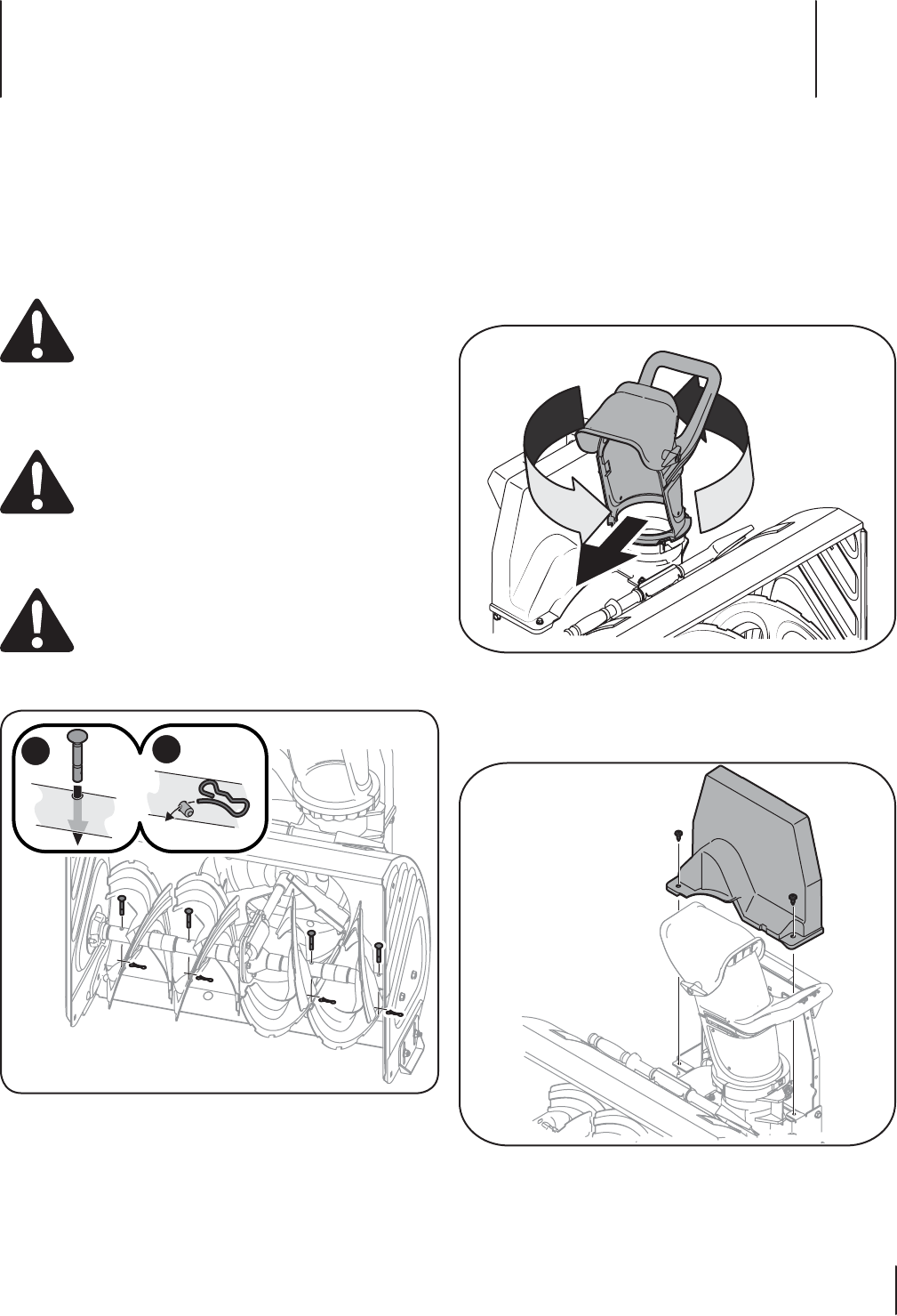
1. Replace the shear pins as shown in Figure 7-1.
12
Figure 7-1
Note: Two replacement shear pins and bow-tie cotter pins
were included with this attachment.
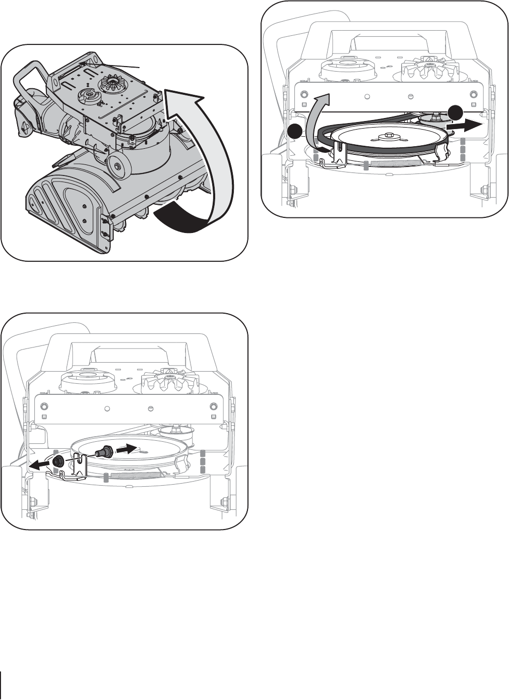
Replacing the Auger Belt
2. Uncouple the FLEX™ Snow Thrower attachment from the
FLEX™ Base Unit by deploying the kickstand and tipping
the base unit forward. Carefully move the base unit
backwards and away from the snow thrower attachment.
3. Park the FLEX™ Base Unit in a safe and stable location.
4. Rotate the discharge chute to the right as shown in Figure
7-2.
Figure 7-2
3. Remove the two self-tapping screws shown in Figure 7-3,
and lift the belt cover up and away from this device. Set it
and the screws aside and save.
Figure 7-3
16 Section 7— Service
4. Carefully tip the FLEX™ Snow Thrower Attachment forward
onto the front of the auger housing as shown. Use the
mounting handle called out in Figure 7-4 to tip this unit
forward. NEVER use the chute handle to either tip this unit
forward, for lifting or any other reason other than rotating
the discharge chute left or right.
Mounting Handle
Figure 7-4
5. Remove the belt keeping should bolt and lock nut and
retain for later reinstallation. See Figure 7-5.
Figure 7-5
6. Pull the idler pulley outward (1 in Figure 7-6) to relieve the
tension on the auger belt.
7. Roll the belt off of the large auger pulley, as shown in 2 of
Figure 7-6, then off of the upper pulley.
Note: When reinstalling the new belt, be sure that it routes
INSIDE of the idler pulley as shown in 1 of Figure 7-6.
2
1
Figure 7-6
8. Reinstall the shoulder bolt belt keeper, then tip the unit
upright using the Mounting Handle, as detailed in , then
reinstall the belt cover with the two tap screws that were
removed.

Troubleshooting 8
17
Problem Cause Remedy
Excessive vibration or noise
when the Attachment
Control Lever is applied.
1. One or more of the clutch bumpers is missing
or worn.
2. Loose parts or damaged auger.
1. Replace the three clutch bumpers with
replacement kit part no. 753-08457.
2. Stop engine immediately and disconnect
spark plug wire. Check for possible damage.
Tighten all bolts and nuts. Repair as needed.
If the problem persists, take unit to an
authorized service dealer.
Augers continue to rotate 1. Cable out of adjustment. 1. Adjust the auger control cable as shown in
the Maintenance Section under “Adjusting
the Auger Drive Cable”.
Unit fails to discharge snow 1. Chute assembly clogged.
2. Shear pin(s) sheared.
3. Foreign object lodged in auger.
4. Auger control cable out of adjustment.
5. Auger belt loose or damaged.
1. Stop engine and disconnect spark plug wire.
Clean chute and inside of auger housing with
clean-out tool or stick.
2. Replace shear pin(s).
3. Stop engine immediately and disconnect the
spark plug wire. Remove object from auger.
4. Adjust auger control cable.
5. Replace auger belt.
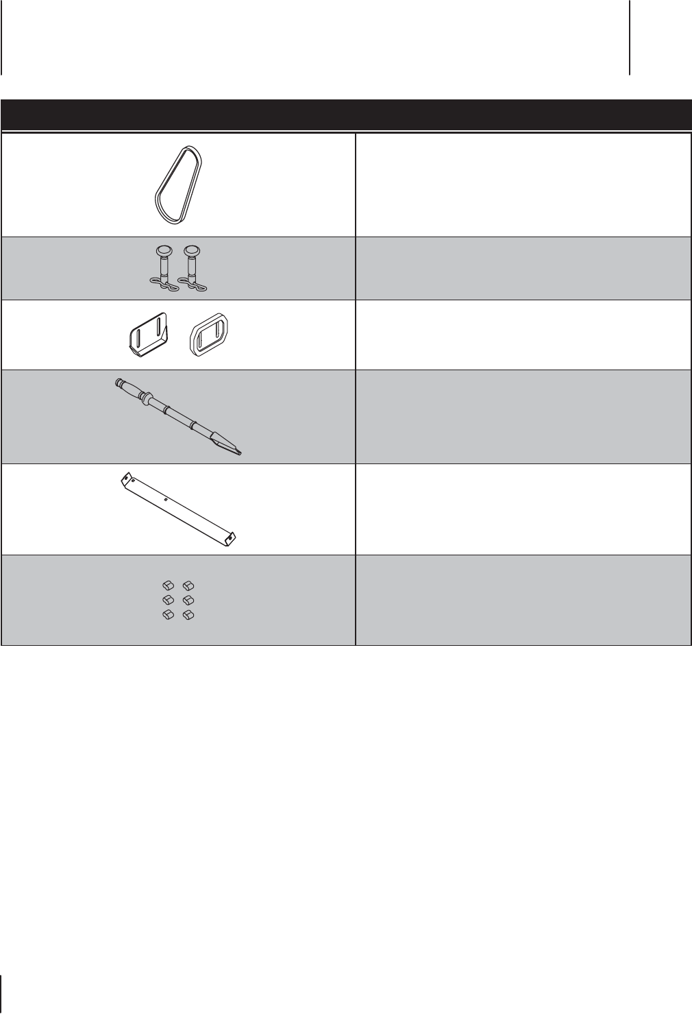
Component Part Number and Description
954-05071 Auger Drive Belt
738-04124A Shear Pin, 1.50
714-04040 Bow-tie Cotter Pin
784-5580 Skid Shoe, Standard (steel)
931-2643 Chute Clean-out Tool
790-00121 Shave Plate
753-08457 Clutch Bumper Kit (6)
Phone (800) 828-5500 to order replacement parts or a complete Parts Manual (have your full model number and serial number ready).
Parts Manual downloads are also available free of charge at www.troybilt.com.
Replacement Parts 9
18

Notes 10
19

20 Section 10 — noteS

21Section 10 — noteS

LIMITED WARRANTY FOR FLEX ATTACHMENT PRODUCT
079221 REV. A
5. Any expendable, consumable, or routine maintenance item which
needs replacement or service as part of normal maintenance, unless
such items have defects that cause failure or premature wear within
the first thirty (30) days. Where applicable, normal wear items include
but are not limited to, blades, tires, belts, filters, fuses, and other
consumable items
6. Any Attachment that has been altered or modified in a manner not
consistent with the original design of the product or in a manner not
otherwise approved by Troy-Bilt LLC.
7. Paint repairs or replacements for defective paint (including materials
and application) are covered for a period of three (3) months.
8. Wheel rims are covered for a period of three (3) months for
manufacturing defects.
9. The FLEX Power Base is covered by a separate limited warranty which
is contained in the operator’s manual for the FLEX Power Base.
This warranty does not cover and Troy-Bilt LLC disclaims any
responsibility for:
1. Loss of time or loss of use of the Attachment.
2. Transportation costs and other expenses incurred in connection with
the transport of the Attachment to and from the authorized Troy-Bilt
service provider.
3. Any loss or damage to other equipment or personal items.
4. Damage caused by performance or use of the Attachment in
connection with any product other than the FLEX Power Base.
Limitations:
1. THERE ARE NO IMPLIED WARRANTIES, INCLUDING, BUT NOT LIMITED
TO, ANY IMPLIED WARRANTY OF MERCHANTABILITY OR FITNESS FOR A
PARTICULAR PURPOSE. NO WARRANTY APPLIES AFTER THE APPLICABLE
WARRANTY PERIOD AS SET FORTH ABOVE AS TO THE PARTS AS
IDENTIFIED. NO OTHER EXPRESS WARRANTY OR GUARANTY, WHETHER
WRITTEN OR ORAL, EXCEPT AS MENTIONED ABOVE, GIVEN BY ANY
PERSON OR ENTITY, INCLUDING A DEALER OR RETAILER, WITH RESPECT
TO ANY PRODUCT SHALL BIND TROY-BILT LLC. DURING THE WARRANTY
PERIOD, THE EXCLUSIVE REMEDY IS REPAIR OR REPLACEMENT OF THE
DEFECTIVE PART, AS SET FORTH ABOVE. (SOME STATES DO NOT ALLOW
LIMITATIONS ON HOW LONG AN IMPLIED WARRANTY LASTS, SO THE
ABOVE LIMITATION MAY NOT APPLY TO YOU.)
2. THE PROVISIONS AS SET FORTH HEREIN PROVIDE THE SOLE AND
EXCLUSIVE REMEDY ARISING FROM THE SALE. TROY-BILT SHALL NOT
BE LIABLE FOR INCIDENTAL OR CONSEQUENTIAL LOSS OR DAMAGES
INCLUDING, WITHOUT LIMITATION, FOR TRANSPORTATION OR FOR
RELATED EXPENSES, OR FOR RENTAL EXPENSES TO TEMPORARILY
REPLACE A WARRANTED PRODUCT. (SOME STATES DO NOT ALLOW
THE EXCLUSION OR LIMITATION OF INCIDENTAL OR CONSEQUENTIAL
DAMAGES, SO THE ABOVE EXCLUSION OR LIMITATION MAY NOT APPLY
TO YOU.)
3. In no event shall recovery of any kind be greater than the amount of the
purchase price of the product sold. Alteration of the safety features of the
product shall void this limited warranty. You assume the risk and liability
for loss, damage, or injury to you and your property and/or to others
and their property arising out of the use or misuse or inability to use the
product.
How State Law Relates to this Warranty:
This limited warranty gives you specific legal rights, and you may also have
other rights which vary from state to state.
Troy-Bilt LLC, P.O. BOX 361131 CLEVELAND, OHIO 44136-0019; Phone: 1-800-828-5500, 1-330-558-7220
MTD Canada Limited - KITCHENER, ON N2G 4J1; Phone 1-800-668-1238
The limited warranty set forth herein is given by Troy-Bilt LLC to the Initial
Purchaser (as defined herein) with respect to a new Troy-Bilt-branded FLEX
attachment product consisting of one of the following four (4) attachments
to the FLEX Power Base (referred to hereafter as the “Attachment”): (i) wide
area mower, (ii) snow-thrower, (iii) pressure washer or (iv) leaf blower. This
limited warranty does not cover Emission Control Systems and is not a
Federal Emission Control Warranty Statement as defined by U.S. federal
law. Please refer to the Federal Emission Control Warranty Statement in
the operator’s manual for the FLEX Power Base product (“Power Base”) for
warranties covering Emission Control Systems.
Scope of the Limited Warranty
Troy-Bilt LLC offers the following limited warranty to the Initial Purchaser for
residential or otherwise non-commercial use of the Attachment on the FLEX
Power Base: except for the Exclusions (defined herein), during the Warranty
Period (defined herein), the Attachment will be free from manufacturing
defects (including workmanship and materials). The “Initial Purchaser” is the
first person to purchase a new Attachment from an authorized Troy-Bilt dealer,
distributor and/or retailer of such attachment products. This limited warranty
is non-transferrable. Except as otherwise set forth herein, the limited warranty
period for this new Attachment purchased by the Initial Purchaser is two (2)
years from the date of purchase as shown on the original sales receipt for the
Attachment (“Warranty Period”).
Defects in Workmanship or Materials
Except for the Exclusions, the Attachment is warranted to be free from
manufacturing defects in either workmanship or materials for the Warranty
Period. During the Warranty Period, Troy-Bilt LLC will, at its option, either
repair or replace any original part that is covered by this limited warranty and
is determined to be defective in workmanship or material.
To qualify for this limited warranty the FLEX™ Base Unit:
1. Must have been purchased from an authorized Troy-Bilt retailer.
2. Must have been purchased within the United States by the Initial
Purchaser.
3. Must have been used for residential or otherwise non-commercial
purposes.
4. Must have been used in a manner consistent with the normal and
proper intended use for the Attachment. This Attachment is not
intended for rental or commercial use.
Who can perform repairs under this warranty?
In order to qualify for the limited warranty as set forth herein, the repairs made
under this warranty must be performed by an authorized Troy-Bilt service
provider.
How to get service under this limited warranty:
To locate a Troy-Bilt warranty service provider, contact your authorized
Troy-Bilt dealer, distributor and/or retailer or contact Troy-Bilt LLC at P.O. Box
361131, Cleveland, Ohio 44136-0019 or call 1-877-282-8684 or log on to our
Website at www.troybilt.com. This limited product warranty is provided
by Troy-Bilt LLC and is the only product warranty provided by Troy-Bilt LLC
for this Attachment. A COPY OF YOUR SALES RECEIPT IS REQUIRED FOR
WARRANTY SERVICE.
What this limited warranty does not cover.
This limited warranty does not cover the following (the “Exclusions”):
1. Attachment purchased outside of the United States.
2. Damage due to lack of maintenance and/or improper maintenance as
described in the operator’s manual.
3. Normal wear and tear resulting from use of the Attachment.
4. Use of the Attachment that is not consistent with the intended use
thereof as described in the operating instructions, including, but not
limited to, abuse, misuse and/or neglect of the Attachment or any use
inconsistent with and/or non-compliant with instructions contained in
the Operator’s Manual.

Asistencia al Cliente
Por favor, NO devuelva la máquina al minorista o distribuidor sin ponerse en contacto primero
con el Departamento de Asistencia al Cliente.
Si tiene dificultad para armar este producto o tiene dudas respecto a los controles, el funcionamiento o el mantenimiento de esta máquina,
puede solicitar la ayuda de expertos. Seleccione una de las opciones siguientes:
◊ Visite nuestro sitio web en www.troybilt.com
Vea videos instructivos sobre el mantenimiento y la instalación de piezas en www.troybilt.com/tutorials
◊ Llame a un representante de Asistencia al Cliente al (800) 828-5500 ó (330) 558-7220
◊ Escriba a Troy-Bilt LLC • P.O. Box 361131 • Cleveland, OH • 44136-0019
Gracias por comprar el Accesorio quitanieve FLEX™ Troy-Bilt.
El mismo ha sido cuidadosamente diseñado para brindar excelente
rendimiento si se lo opera y mantiene correctamente.
Por favor lea todo este manual antes de hacer funcionar el equipo.
El manual le indica cómo configurar, operar y mantener la
máquina de manera fácil y segura. Por favor asegúrese de que
usted, y cualquier otra persona que haga funcionar la máquina,
sigue atentamente y en todo momento las medidas de seguridad
recomendadas. En caso de no hacerlo podrían producirse lesiones
personales o daños materiales.
Toda la información contenida en este manual hace referencia a la
más reciente información de producto disponible en el momento
de la impresión. Revise el manual frecuentemente para
familiarizarse con la máquina, sus características y funcionamiento.
Por favor tenga en cuenta que este Manual del Operador puede
cubrir una gama de especificaciones para productos de varios
modelos. Es posible que las características y funciones incluidas
y/o ilustradas en este manual no se apliquen a todos los modelos.
Nos reservamos el derecho de modificar las especificaciones de
los productos, diseños y equipos sin previo aviso y sin generar
responsabilidad por obligaciones de ningún tipo.
Si tiene algún problema o duda respecto a la máquina, llame a
un distribuidor de servicio Troy-Bilt autorizado o comuníquese
directamente con nosotros. En esta página encontrará los números
de teléfono, dirección del sitio web y dirección postal de Atención
al cliente de Troy-Bilt. Queremos garantizar su entera satisfacción en
todo momento.
En este manual, todas las referencias al lado derecho e izquierdo de la
máquina se observan desde la posición del operador
Gracias
Registro de información de producto
Antes de configurar y hacer funcionar su equipo nuevo, por favor
localice la placa de modelo en el equipo y registre la información en
el espacio de la derecha. Podrá localizar la placa de modelo si la busca
en la placa de montaje posterior del accesorio quitanieve SIN que
esté colocada la unidad base. Si tiene que solicitar soporte técnico
a través de nuestro sitio web, el Departamento de Asistencia al
Cliente, o de un distribuidor de servicio autorizado local, necesitará
esta información
NúMero de Modelo
NúMero de Serie
Al propietario 1
23
Medidas de seguridad .............................................. 24
Montaje y Conguración .......................................... 28
Controles .................................................................... 31
Funcionamiento ........................................................ 32
Mantenimiento y ajustes .......................................... 34
Servicio ....................................................................... 36
Solución De Problemas ............................................38
Piezas de repuesto .................................................... 39
Garantía ..................................................................... 40
Índice

Importantes medidas de seguridad 2
24
Capacitación
1. Lea, entienda y cumpla todas las instrucciones incluidas en
la máquina y en el(los) manual(es) antes de intentar realizar
el montaje de la unidad y utilizarla. Guarde este manual en
un lugar seguro para consultas futuras y periódicas, así como
para solicitar repuestos.
2. Familiarícese con todos los controles y con el uso adecuado
de los mismos. Sepa cómo detener la máquina y desactivar los
controles rápidamente.
3. No permita nunca que los niños menores de 14 años utilicen
esta máquina. Los niños de 14 años en adelante deben
leer y entender las instrucciones y las normas de seguridad
contenidas en este manual y en la máquina y deben ser
entrenados y supervisados por un adulto.
4. Nunca permita que los adultos operen esta máquina sin recibir
antes la instrucción apropiada.
5. Los objetos arrojados por la máquina pueden causar lesiones
graves. Planifique el patrón en el que va a ir arrojando nieve
para evitar que la descarga de material se realice hacia los
caminos, los observadores, etc.
6. Mantenga a los observadores, mascotas y niños por lo menos
a 75 pies de la máquina siempre que esté funcionando.
Detenga la máquina si alguien se acerca.
7. Sea precavido para evitar patinarse o caerse especialmente
cuando opera la máquina en marcha atrás.
Preparativos
Inspeccione minuciosamente el área donde utilizará el equipo.
Saque todos los felpudos, periódicos, trineos, tablas, cables y otros
objetos extraños con los que podría tropezar o que podrían ser
arrojados por la barrena/impulsor.
1. Para protegerse los ojos utilice siempre anteojos o antiparras
de seguridad mientras opera la máquina o mientras la ajusta
o repara. Los objetos arrojados que rebotan pueden causar
lesiones graves en los ojos.
2. No opere la máquina sin la vestimenta adecuada para estar al
aire libre en invierno. No utilice alhajas, bufandas largas u otras
prendas sueltas que podrían enredarse en las partes móviles.
Utilice un calzado especial para superficies resbaladizas.
3. Use un prolongador y un tomacorriente de tres cables con
conexión a tierra para todas las máquinas con motores de
encendido eléctrico.
4. Ajuste la altura de la caja de la barrena para limpiar la grava
o las superficies con piedras trituradas.
5. Desengrane todas las palancas de control antes de arrancar
el motor.
6. Nunca intente hacer ajustes mientras el motor está en marcha,
excepto cuando así lo recomiende específicamente el manual
del operador.
7. Deje que el motor y la máquina se adapten a la temperatura
exterior antes de comenzar a sacar la nieve.
¡ADVERTENCIA! La presencia de este símbolo indica que se trata de instrucciones de seguridad
importantes que se deben respetar para evitar poner en peligro su seguridad personal y/o material
y la de otras personas. Lea y cumpla todas las instrucciones de este manual antes de intentar operar
esta máquina. Si no respeta estas instrucciones puede provocar lesiones personales.
Cuando vea este símbolo. ¡TENGA EN CUENTA LA ADVERTENCIA!
PELIGRO: Esta máquina está diseñada para ser utilizada respetando las normas de seguridad
contenidas en este manual. Al igual que con cualquier tipo de equipo motorizado, un descuido
o error por parte del operador puede producir lesiones graves. Esta máquina es capaz de amputar
dedos, manos y pies y de arrojar objetos extraños con gran fuerza. De no respetar las instrucciones
de seguridad siguientes se pueden ocasionar lesiones graves o la muerte.
PROPOSICIÓN 65 DE CALIFORNIA
¡ADVERTENCIA! El escape del motor, algunos de los elementos del mismo y algunos
componentes del vehículo contienen o liberan sustancias químicas que según el Estado de
California pueden producir cáncer, defectos de nacimiento u otros problemas reproductivos.

25Sección 2 — importanteS medidaS de Seguridad
Manejo seguro de la gasolina
Para evitar lesiones personales o daños materiales tenga mucho
cuidado al manipular la gasolina. La gasolina es sumamente
inflamable y sus vapores pueden causar explosiones. Si se derrama
gasolina encima o sobre la ropa se puede lesionar gravemente ya que
se puede encender. Lávese la piel y cámbiese de ropa de inmediato.
a. Utilice sólo los recipientes para gasolina autorizados.
b. Apague todos los cigarrillos, cigarros, pipas y otras
fuentes de combustión.
c. Nunca cargue combustible en la máquina en un
espacio cerrado.
d. Nunca saque la tapa del combustible ni agregue
combustible mientras el motor está caliente o en marcha.
e. Deje que el motor se enfríe por lo menos dos minutos
antes de volver a cargar combustible.
f. Nunca llene en exceso el depósito de combustible.
Llene el tanque a no más de ½ pulgada por debajo de
la base del cuello de llenado dejando espacio para la
dilatación del combustible.
g. Vuelva a colocar el tapón de combustible y ajústelo bien.
h. Limpie el combustible que se haya derramado sobre
el motor y el equipo. Traslade la máquina a otra zona.
Espere 5 minutos antes de encender el motor.
i. Nunca almacene la máquina o el recipiente de
combustible en un espacio cerrado donde haya fuego,
chispas o luz piloto (por ejemplo, hornos, calentadores
de agua, calefactores, secadores de ropa, etc.).
j. Deje que la máquina se enfríe por lo menos 5 minutos
antes de guardarla.
k. Nunca llene los recipientes dentro de un vehículo
o un camión o un remolque con recubrimiento plástico.
Coloque siempre los recipientes en el piso y lejos del
vehículo antes de llenarlo.
l. Si es posible, retire el equipo a gasolina del camión
o remolque y llénelo en el suelo. Si esto no es posible,
llene el equipo en un remolque con un recipiente
portátil, en vez de hacerlo desde una boquilla
dispensadora de gasolina.
m. En todo momento mantenga la boquilla en contacto con
el borde del depósito de combustible o con la abertura
del recipiente, hasta terminar la carga. No utilice un
dispositivo de apertura/cierre de la boquilla,
Funcionamiento
1. No ponga las manos o los pies cerca de las piezas giratorias,
en la caja de la barrena / impulsor o en el montaje del canal
de descarga. El contacto con las piezas giratorias puede
amputar manos y pies.
2. La palanca de control de la barrena / impulsor es un dispositivo
de seguridad. Nunca evite su funcionamiento. De hacerlo la
operación de la máquina es riesgosa y puede ocasionar lesiones.
3. Las palancas de control deben funcionar bien en ambas
direcciones y regresar automáticamente a la posición de
desengrane cuando se las suelta.
4. Nunca opere la máquina si falta un montaje del canal o si
el mismo está dañado. Mantenga todos los dispositivos de
seguridad en su lugar y en funcionamiento.
5. Nunca encienda el motor en espacios cerrados o en una zona
con poca ventilación. El escape del motor contiene monóxido
de carbono, un gas inodoro y letal.
6. No utilice la máquina bajo la influencia de alcohol o drogas.
7. El silenciador y el motor se calientan y pueden causar
quemaduras. No los toque. Mantenga a los niños alejados.
8. Tenga mucho cuidado si cruza o usa la máquina en superficies
con grava. Manténgase atento al tráfico y los riesgos ocultos.
9. Tenga cuidado cuando cambie de dirección o cuando
opere la máquina en pendientes. No la utilice en pendientes
pronunciadas.
10. Planifique el patrón en el que va a ir arrojando nieve para evitar
que la descarga de material se produzca hacia las ventanas,
las paredes, los automóviles, etc. y evitar así posibles daños
materiales o lesiones producidas por los rebotes.
11. Nunca dirija la descarga hacia los niños, los observadores o las
mascotas ni deje que nadie se pare delante de la máquina.
12. No sobrecargue la capacidad de la máquina tratando de sacar
la nieve muy rápidamente.
13. Nunca opere esta máquina si no cuenta con buena visibilidad o
luz. Siempre esté seguro de dónde apoya los pies y mantenga
con firmeza las manos en las manijas. Camine, nunca corra.
14. Corte la corriente a la barrena/impulsor cuando transporte
la máquina o cuando la misma no está en uso.
15. Nunca opere la máquina a alta velocidad de desplazamiento
sobre superficies resbaladizas. Mire hacia abajo y hacia atrás
y tenga cuidado cuando vaya marcha atrás.
16. Si la máquina comenzara a vibrar de manera anormal, detenga
el motor, desconecte el cable de la bujía y póngala de manera
que haga masa contra el motor. Revise cuidadosamente para
detectar daños. Repare cualquier daño antes de encender el
motor y operar la máquina.
17. Desengrane todas las palancas de control y detenga el motor
antes de dejar la posición de operación (detrás de las manijas).
Espere a que la barrena/impulsor se detenga por completo
antes de destapar el montaje del canal o realizar ajustes e
inspecciones.
18. Nunca ponga las manos en las aberturas de descarga o de
recolección. Utilice siempre la herramienta de limpieza que se
adjunta para destapar la abertura de descarga. No destape el
montaje del canal mientras el motor está en funcionamiento.
Antes de destaparlo, apague el motor y permanezca detrás de
las barras de control hasta que todas las partes móviles
se hayan detenido.
19. Use sólo uniones y accesorios aprobados por el fabricante
(por ejemplo, pesas para las ruedas, cadenas para los
neumáticos, cabinas, etc.).
20. Para encender el motor, tire lentamente del cordel hasta sentir
resistencia, luego tire rápidamente. El repliegue rápido de la
cuerda de arranque (retroceso o rebote) le jalará la mano y el
brazo hacia el motor más rápido de lo que usted puede soltar.
Puede llegar a causar huesos rotos, fracturas, hematomas
y esguinces.
21. Si se presentan situaciones que no están previstas en este
manual, tenga cuidado y use el sentido común. Póngase
en contacto con Asistencia al Cliente para solicitar ayuda
y el nombre del distribuidor de servicio más cercano.

26 Sección 2 — importanteS medidaS de Seguridad
Despeje de un canal de descarga obstruido
El contacto de las manos con el impulsor rotatorio que está dentro
del canal de descarga es la causa más común de lesiones asociadas
con las máquinas quitanieve. Nunca use las manos para limpiar el
canal de descarga.
Para despejar el canal:
1. ¡APAGUE EL MOTOR!
2. Espere 10 segundos para estar seguro de que las cuchillas
del motor han dejado de rotar.
3. Utilice siempre una herramienta de limpieza, no use las manos.
Mantenimiento y almacenamiento
1. Nunca altere los dispositivos de seguridad. Controle
periódicamente que funcionen correctamente. Remítase
a las secciones de mantenimiento y ajuste de este manual.
2. Antes de realizar la limpieza, reparar o revisar la máquina,
desengrane todas las palancas de control y detenga el motor.
Espere a que la barrena/impulsor se detenga por completo.
Desconecte el cable de la bujía y póngalo haciendo masa
contra el motor para evitar que se encienda accidentalmente.
3. Controle a intervalos frecuentes que los pernos y tornillos estén
bien apretados para mantener la máquina en condiciones de
uso seguro. Además, haga inspecciones visuales de la máquina
para verificar si sufrió algún daño.
4. No cambie la configuración del regulador del motor ni acelere
demasiado el mismo. El regulador del motor controla la
velocidad máxima de funcionamiento seguro del motor.
5. Las placas de raspado y las zapatas antideslizantes que se
usan con la máquina quitanieve se desgastan y se dañan. Para
proteger su seguridad, verifique frecuentemente todos los
componentes y reemplácelos sólo con partes de los fabricantes
de equipo original (OEM). “El uso de repuestos que no cumplen
con las especificaciones del equipo original puede resultar en
rendimiento inadecuado y puede comprometer la seguridad.”
6. Revise las palancas de control periódicamente para verificar
que engranen y desengranen adecuadamente y ajústelos si es
necesario. Consulte la sección de ajustes de este manual del
operador para obtener instrucciones.
7. Mantenga o reemplace las etiquetas de seguridad y de
instrucciones según sea necesario.
8. Observe las leyes y reglamentos sobre la correcta disposición
del gas, el petróleo, etc., para proteger el medio ambiente.
9. Antes de almacenar la máquina enciéndala unos minutos para
sacar la nieve que haya quedado en la misma y para evitar así
que se congele la barrena/impulsor.
10. Nunca almacene la máquina o el recipiente de combustible
en un espacio cerrado donde haya fuego, chispas o luz piloto
como por ejemplo, calentadores de agua, hornos, secadores
de ropa, etc.
11. Consulte siempre el manual del operador para obtener
instrucciones adecuadas para el almacenamiento fuera
de temporada.
12. Verifique frecuentemente la línea de combustible, el depósito,
el tapón, y los accesorios buscando rajaduras o pérdidas.
Reemplace cuando sea necesario.
13. No dé arranque al motor si no está la bujía de encendido.
14. Según la Comisión de Seguridad de Productos para el
Consumidor de los Estados Unidos (CPSC) y la Agencia de
Protección Ambiental de los Estados Unidos (EPA), este
producto tiene una vida útil media de siete (7) años ó 60
horas de funcionamiento. Al finalizar la vida útil media haga
inspeccionar anualmente esta unidad por un distribuidor de
servicio autorizado para cerciorarse de que todos los sistemas
mecánicos y de seguridad funcionan correctamente y no
tienen excesivo desgaste. Si no lo hace, puede ocasionar
accidentes, lesiones o la muerte.
No modifique el motor
Para evitar lesiones graves o la muerte, no modifique el motor de
ninguna manera. Si altera la configuración del regulador, el motor
se puede desbocar y funcionar a velocidades que no son seguras.
Nunca cambie la configuración de fábrica del regulador del motor.
Aviso referido a emisiones
Los motores que están certificados y cumplen con las normas sobre
emisiones federales EPA y de California para SORE (Equipos pequeños
todo terreno) están certificados para funcionar con gasolina sin
plomo común y pueden incluir los siguientes sistemas de control
de emisiones: Modificación de motor (EM), catalizador oxidante (OC),
inyección de aire secundaria (SAI) y catalizador de tres vías (TWC)
si están instalados.
Amortiguador de chispas
¡ADVERTENCIA! Esta máquina está equipada con
un motor de combustión interna y no debe ser utilizada
en o cerca de un terreno agreste cubierto por bosque,
malezas o hierba excepto que el sistema de escape del
motor esté equipado con un amortiguador de chispas
que cumpla con las leyes locales o estatales
correspondientes (en caso de existir).
Si se utiliza un amortiguador de chispas el operador lo debe
mantener en condiciones de uso adecuadas. En el Estado de
California las medidas anteriormente mencionadas son exigidas
por ley (Artículo 4442 del Código de Recursos Públicos de California).
Es posible que existan leyes similares en otros estados. Las leyes
federales se aplican en los territorios federales.
Puede conseguir el amortiguador de chispas para el silenciador a
través de su distribuidor de mantenimiento de motores autorizado
más cercano o poniéndose en contacto con el departamento de
servicios, P.O. Box 361131 Cleveland, Ohio 44136-0019.

27Sección 2 — importanteS medidaS de Seguridad
Símbolos de seguridad
En esta página se presentan y describen los símbolos de seguridad que en este producto puede tener. Lea, entienda y siga todas las
instrucciones incluidas en la máquina antes de intentar armarla y hacerla funcionar.
Símbolo Descripción
LEA LOS MANUALES DEL OPERADOR
Lea, entienda y siga todas las instrucciones incluidas en los manuales antes de intentar armarla
y hacerla funcionar.
ADVERTENCIA— BARRENA GIRATORIA
Evite lesiones por la barrena giratoria. Mantenga alejados las manos, los pies y la vestimenta.
ADVERTENCIA – CUCHILLAS GIRATORIAS
Mientras la máquina está en funcionamiento, mantenga las manos lejos de las aberturas de entrada
y de descarga. En el interior hay cuchillas giratorias
¡ADVERTENCIA! Su responsabilidad—Limite el uso de esta máquina motorizada a las personas que lean,
comprendan y respeten las advertencias e instrucciones que figuran en este manual y en la máquina.
¡GUARDE ESTAS INSTRUCCIONES!
Montaje y Configuración 3
28
Montaje
Instalación del canal de descarga
Con el presente accesorio se incluyó un canal de descarga, un
resorte de alambre y una banda para canal. Ensámblelos ahora,
para lo que debe instalar el canal de descarga en el accesorio
quitanieve siguiendo estos pasos:
1. Instale el resorte de alambre en la abertura de descarga
del accesorio quitanieve para lo cual debe insertar ambos
extremos en las ranuras provistas. Consulte la Figura 3-1
para conocer la ubicación y la orientación adecuadas del
resorte. En el recuadro de la Figura 3-1 se muestra el resorte
correctamente instalado con los extremos colocados en las
ranuras provistas.
Figura 3-1
2. Coloque el canal de descarga, que se embala suelto en la caja,
en el accesorio quitanieve, como se indica en la Figura 3-3.
Nota: Ubique el canal de descarga inclinado hacia la derecha
para facilitar la instalación.
3. Sujete la manija del canal de descarga al canal de descarga,
como se indica en la Figura 3-2.
Figura 3-2
Figura 3-3
4. Coloque la banda para el canal como se indica en la Figura
3-4. Con el canal de descarga ubicado hacia la derecha como
se indica, coloque la banda del canal alineando las ranuras
del frente con la banda, y asegurándose de calzar el canal de
descarga dentro del canal de la banda para el canal, como se
indica en el recuadro de la Figura 3-4.
Figura 3-4
29Sección 3 — Montaje y configuración
5. Sujete la banda para el canal al canal alineando primero
las dos uniones de ajuste a presión y oprimiendo los dos
extremos (1 y 2) para unirlos como se indica. Asegúrese de
que las dos lengüetas de los extremos queden enganchadas,
como se indica en el recuadro superior izquierdo de la Figura
3-5. Si se ensambla correctamente, la banda para el canal debe
quedar como se muestra en el recuadro superior derecho de
la Figura 3-5.
1
2
Figura 3-5
IMPORTANTE: Si debe extraer el canal por cualquier motivo, se
debe usar un destornillador para soltar las lengüetas de traba que se
mostraron anteriormente en el recuadro izquierdo de la Figura 3-5.
Nota: Si la instalación se realizó correctamente, se oirá un
sonido como ¡clic! ¡clic! ¡clic! al girar el canal hacia la izquierda
y la derecha. Consulte la Figura 3-6.
Figura 3-6
Configuración
Ajuste de las zapatas antideslizantes
Las zapatas antideslizantes de la máquina quitanieve se ajustan
hacia arriba en fábrica para el envío. Si lo desea, puede ajustarlas
hacia abajo antes de hacer funcionar el accesorio quitanieve.
PRECAUCIÓN: Se recomienda no operar este
accesorio quitanieve sobre grava ya que la unidad
puede recoger y lanzar grava suelta fácilmente,
causando lesiones personales o daños a la máquina
y los objetos que la rodean.
• Si desea quitar nieve en una superficie lisa, eleve más las
zapatas antideslizantes en la caja de la barrena.
• Use las posiciones media o baja cuando la superficie que
desea limpiar es despareja, tal como un camino de grava.
NOTA: Si tiene que usar la máquina quitanieve sobre grava,
mantenga las zapatas antideslizantes en la posición que
permita lograr una separación máxima entre el piso y la
placa de raspado.
PRECAUCIÓN: Si se utiliza una máquina quitanieves
que está equipada con zapatas antideslizantes de acero
se pueden provocar daños a las superficies que tengan
pavimento natural (por ejemplo arenisca, piedra azul,
piedra caliza). Consulte las secciones de Piezas de
Reemplazo o Accesorios y Complementos para obtener
más información sobre las zapatas antideslizantes de
polímero disponibles.
Para ajustar las zapatas antideslizantes:
1. Afloje las cuatro tuercas hexagonales (dos en cada lado)
y los pernos del carro. Mueva las zapatas antideslizantes
a la posición deseada. Consulte la Figura 3-7.
2. Compruebe que toda la superficie inferior de las zapatas
antideslizantes esté contra el suelo para evitar el desgaste
desparejo de las mismas.
3. Vuelva a ajustar bien las tuercas y los pernos.
Figura 3-7
¡Clic!
¡Clic!
¡Clic!
30 Sección 3 — Montaje y configuración
Canal de descarga
La posición del canal de descarga superior se puede ajustar de
manera de controlar la distancia a la que se arrojará la nieve
descargada y la dirección en que será descargada. Siga estos pasos
para ajustar el canal de descarga:
1. Afloje la perilla de aletas del canal superior, ajuste el canal
hasta la posición de funcionamiento deseada.
2. Apriete la perilla de aletas del canal superior asegurándose
de que el perno del carro del interior del canal de descarga
esté ubicado correctamente. Consulte la Figura 3-8.
Figura 3-8
3. Para ajustar la dirección en la que se arrojará la nieve, use
la manija del canal de descarga superior para controlar la
dirección de la descarga. Vuelva a consultar la Figura 3-8.
Pasadores de cuchilla
El accesorio quitanieve trae un par de pasadores de cuchilla de la
barrena y pasadores de chaveta con unión curva de reemplazo.
Consulte la Figura 3-9. Almacénelos en un lugar seguro hasta que
sean necesarios.
Figura 3-9
Herramienta de limpieza del canal
La herramienta de limpieza del canal viene sujeta de fábrica
a la parte superior de la caja de la barrena con un pasador de
ensamblado y un precinto. Corte el precinto antes de operar
la máquina quitanieve. Consulte la Figura 3-10.
Herramienta de
limpieza del canal
Figure 3-10
Motor
Consulte el manual del operador de la unidad de base FLEX™ para
obtener información sobre todos los controles y las características
relacionados con el motor.
Palanca de control de transmisión
Esta palanca impulsa toda la máquina hacia adelante.
Palanca de control del accesorio
Apriete el control de la barrena contra la barra de control superior
para engranar las barrenas, y suéltelo para desengranarlas.
Barrena
Cuando está engranada, la rotación de la barrena dirige la nieve al
interior de la caja de la barrena y la arroja hacia afuera por el canal
de descarga.
Conjunto del canal
La nieve que se empuja al interior de la caja de la barrena
se descarga hacia afuera por el conjunto del canal.
Manija del canal
La dirección en que se arroja la nieve corresponde a la dirección de
apertura del canal. Use la manija del canal para girar el conjunto del
canal en la dirección en la que desee arrojar la nieve.
Perilla del canal
Es posible ajustar la distancia a la cual se arroja la nieve elevando
o bajando el canal superior. Afloje la perilla del canal del lado del
canal superior para ajustarlo. Gire el canal superior hasta la posición
deseada y vuelva a ajustar la perilla del canal.
Placa de raspado
La placa de raspado hace contacto con el pavimento a medida que
se impulsa el accesorio quitanieve, permitiendo que se descargue
la nieve que está cerca de la superficie del pavimento.
Zapatas antideslizantes
Ubique las zapatas antideslizantes en función de las condiciones
de la superficie. Ajuste hacia arriba si la nieve está muy compactada.
Ajústelas hacia abajo si usa la máquina en grava o superficies con
piedras trituradas. Consulte la sección Montaje y Configuración para
obtener información sobre el ajuste de las zapatas antideslizantes.
Herramienta de limpieza del canal
La herramienta de limpieza del canal está sujeta convenientemente
a la parte posterior de la caja de la barrena con un pasador de
ensamblado. Se utiliza para aflojar y recoger la nieve y el hielo que
se formen dentro y cerca del montaje del canal.
Manija del canal
Placa de raspado
Barrena
Canal superior
Perilla del canal
Zapata
antideslizante
Herramienta
de limpieza del canal
Palanca de control
de la transmisión
Palanca de control del accesorio
Bloqueo de la palanca de control del accesorio
Conjunto del canal
Figura 4-1
Controles y Características 4
31
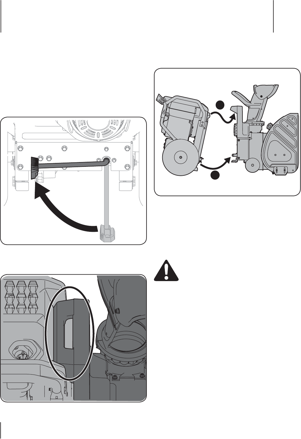
Encendido del motor
Consulte el manual del operador de la base de potencia FLEX™
para obtener las instrucciones para el arranque y el funcionamiento
del motor.
Acople el accesorio quitanieve a la base
de potencia
1. Con el soporte en la posición UP (arriba) en la base de potencia
FLEX™, como se indica en la Figura 5-1, hágalo girar hacia el
accesorio quitanieve.
Figura 5-1
2. Incline la base de potencia FLEX™ hacia adelante, enganchando
la lengüeta de montaje superior con la manija de montaje del
accesorio quitanieve, consulte la Figura 5-2.
Figura 5-2
3. Una vez que se engancha el montaje superior (1), y con ambas
manos en las empuñaduras de las manijas, incline suavemente
la unidad hacia atrás para enganchar los montajes inferiores
(2). Consulte la Figura 5-3.
1
2
Figura 5-3
Nota: El operador podrá oír cuando se enganchan y traban los
montajes inferiores si se realiza el acoplamiento correctamente.
Para desacoplar el accesorio quitanieve de la base de potencia:
Pare completamente el motor de la unidad de potencia antes de
intentar realizar los pasos de mantenimiento o de desacoplar el
accesorio. No intente nunca desacoplar la base de potencia del
accesorio quitanieve CON el motor en marcha.
¡ADVERTENCIA! Apague siempre el motor de
la base de potencia FLEX™ y saque la llave antes de
intentar reemplazar los pasadores de cuchilla o de
desacoplar la base de potencia del accesorio.
1. Ponga el soporte abajo.
2. Incline la base de potencia FLEX™ hacia adelante para
desenganchar los montajes inferiores, luego el montaje superior.
3. Mueva la base de potencia FLEX™ para alejarla del accesorio
quitanieve.
Nota: Con el soporte en la posición en que queda hacia abajo
(para destrabar), la base de potencia FLEX™ quedará apoyada
de manera conveniente en posición de detención.
Funcionamiento 5
32
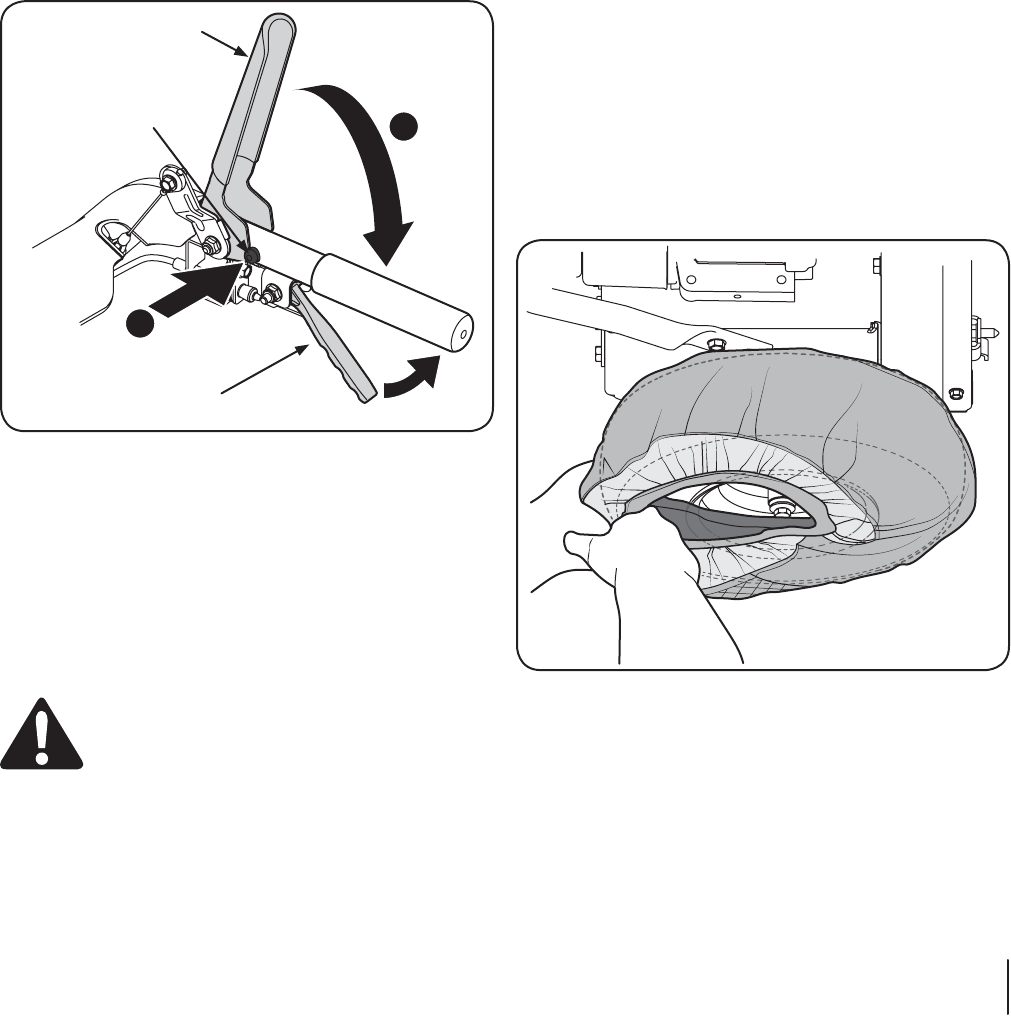
Procedimiento para engranar la transmisión
1. Para activar la transmisión, apriete la palanca de control
de la transmisión completamente contra la manija de control
superior para engranar las ruedas. Para detener la marcha
hacia adelante, suelte el control de la transmisión.
Nota: La palanca de control de la transmisión es un control
de transmisión de velocidad variable. Si se tira de la palanca
de la transmisión completamente hacia adentro, el operador
obtendrá la máxima velocidad, sin embargo, no se alcanzará
dicha velocidad para algunas operaciones, como por ejemplo,
mientras se quita la nieve.
Procedimiento para engranar las barrenas
1. Para engranar las barrenas, oprima el botón de bloqueo
de seguridad de la palanca de control del accesorio
(1 en la Figura 5-4).
2. Oprima completamente la palanca de control del accesorio
contra la manija superior (2). Para detener las barrenas,
suelte la barra.
1
2
Palanca de control de la transmisión
Palanca de control
del accesorio
Bloqueo de seguridad
de la palanca de control
del accesorio
Figura 5-4
Pasadores de cuchilla
Las barrenas están ajustadas al eje espiral con cuatro pasadores
de cuchilla y pasadores de chaveta. La máquina quitanieve ha sido
diseñada para que los pasadores se quiebren si la barrena golpeara
un objeto extraño o un trozo de hielo. Consulte la sección sobre
reparaciones y mantenimiento del presente manual a fin de obtener
las instrucciones para el reemplazo de los pasadores de cuchilla.
Herramienta de limpieza del canal
¡ADVERTENCIA! Nunca use las manos para despejar
un conjunto del canal tapado. Antes de destaparlo,
apague el motor y permanezca detrás de las manijas
de control hasta que todas las partes móviles
hayan detenido.
La herramienta de limpieza del canal está sujeta convenientemente
a la parte posterior de la caja de la barrena con un pasador de
ensamblado. Si se acumulan nieve y hielo en el canal de descarga
durante la operación, proceda como se indica a continuación para
limpiar de manera segura el conjunto del canal y la abertura del canal:
1. Suelte tanto la palanca de control del accesorio como
la palanca de control de la transmisión.
2. Apague el motor como se indica en el manual del motor.
3. Saque la herramienta de limpieza del pasador que la ajusta
a la parte posterior de la caja de la barrena.
4. Use el extremo con forma de pala de la herramienta de
limpieza para desplazar y recoger la nieve y el hielo que
se formen cerca del conjunto del canal.
5. Vuelva a ajustar la herramienta de limpieza al pasador de
montaje que está en la parte posterior de la caja de la barrena
y ponga en marcha el motor del accesorio quitanieve como
se indica en el manual del motor.
Parado en la posición del operador (detrás del accesorio quitanieve),
engrane la palanca de control del accesorio durante unos segundos
para eliminar la nieve o el hielo que hayan quedado en el conjunto
del canal.
Instalación de la funda para nieve para obtener
tracción adicional
Se incluyen dos fundas para nieve con el accesorio quitanieve para
brindar tracción adicional al mover la nieve. Siga estos pasos para
colocar las fundas para nieve:
1. Coloque una funda para nieve en la parte superior de la rueda
de la base de potencia FLEX™, como se indica en la Figura 5-5,
luego pase el resto de la funda por la parte inferior de la rueda.
2. Repita lo mismo en el otro lado.
Nota: Las fundas para nieve están diseñadas para usarse
únicamente durante la remoción de nieve y no están
diseñadas para usarse con ningún otro accesorio FLEX.
Figura 5-5
33Sección 5 — Funcionamiento
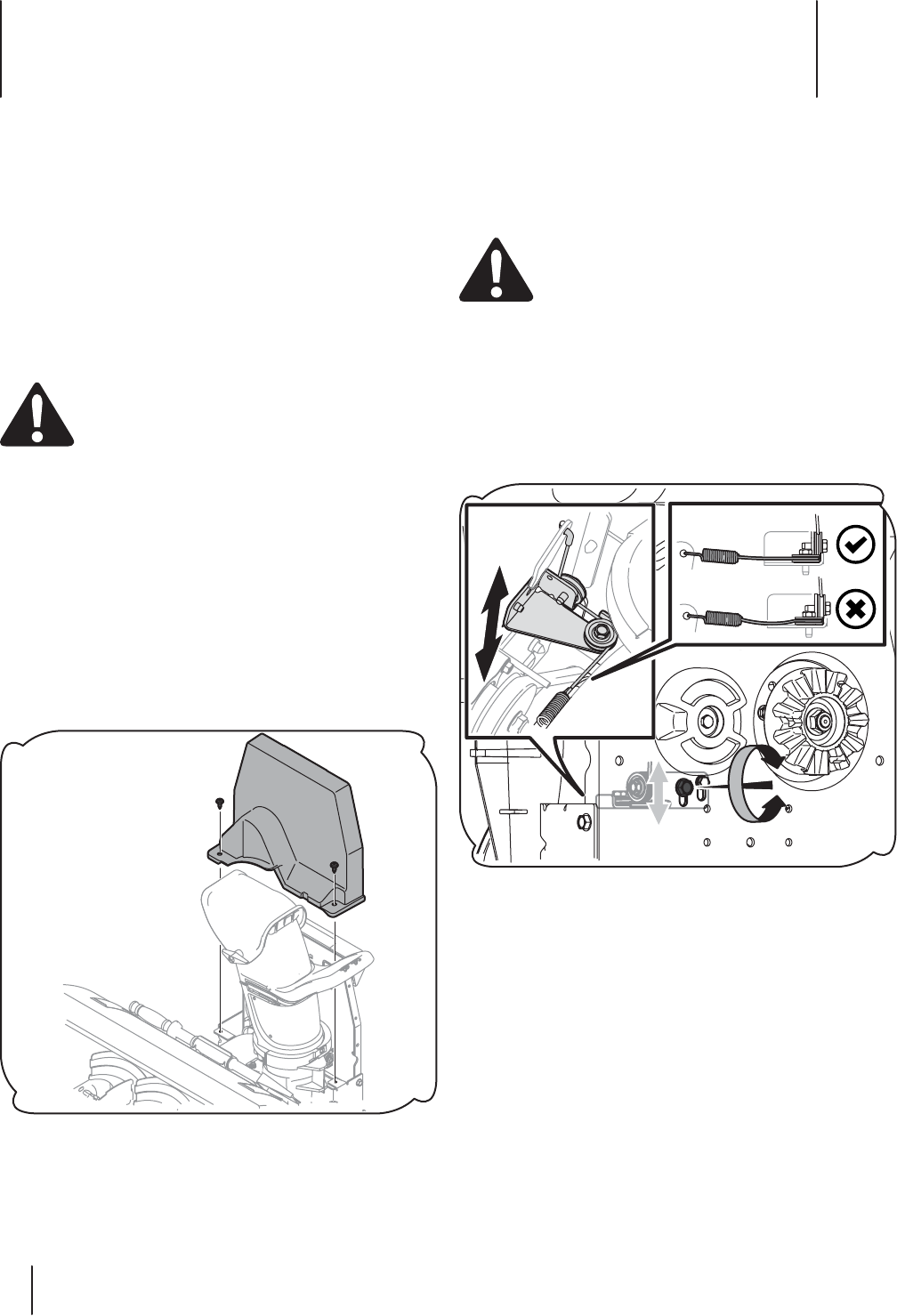
Mantenimiento y Ajustes 6
34
Ajuste del cable de transmisión de la barrena
Después de períodos de uso prolongado y durante el período de
descanso, puede ser necesario ajustar el cable de transmisión de
la barrena. Siga estos simples pasos para ajustar dicho cable:
1. Desacople el accesorio quitanieve de la base de potencia.
¡ADVERTENCIA! Apague siempre el motor de la
base de potencia FLEX™ y saque la llave antes de
intentar desacoplar la base de potencia del accesorio.
2. Retire la cubierta plástica de la correa del accesorio quita nieve,
para lo que debe sacar los tres tornillos autorroscantes que la
sujetan. Vuelva a consultar la Figura 6-1.
3. Observando la placa de montaje posterior del accesorio
quitanieve, afloje (pero no extraiga) el tornillo hexagonal
izquierdo que se muestra en la Figura 6-2.
Nota: El otro tornillo (que está ubicado a la derecha del tornillo
hexagonal [que se aflojó previamente] es un perno con reborde
que no es necesario aflojar.
Figura 6-2
4. En el frente de la placa de montaje, mueva la guía tensora del
cable hacia arriba o abajo para eliminar la holgura del cable
de transmisión de la barrena. Consulte el recuadro izquierdo
de la Figura 6-2.
Nota: Asegúrese de que el ajuste no aplica ningún tipo de
presión sobre el cable y el brazo del actuador. Este ajuste se
realiza simplemente para eliminar el exceso de holgura del
cable de la barrena como se indica en el recuadro izquierdo
de la Figura 6-2.
5. Ajuste el tornillo izquierdo para terminar este ajuste.
Mantenimiento
Recomendaciones generales
• Respete siempre las reglas de seguridad cuando realice
cualquier tipo de mantenimiento.
• La garantía de esta máquina quitanieve no cubre elementos
que han estado sujetos al mal uso o negligencia del operador.
Para recibir el reembolso total de la garantía, el operador
deberá dar mantenimiento a la máquina quitanieve como
se indica en este manual.
• Revise periódicamente todos los sujetadores y los elementos
de ferretería para comprobar que estén bien ajustados.
¡ADVERTENCIA! Antes de realizar tareas de servicio,
reparación, lubricación o inspección, desengrane todos
los controles y detenga el motor. Espere a que se deten-
gan completamente todas las piezas móviles. Desco-
necte el cable de la bujía y póngalo haciendo masa con-
tra el motor para evitar que se encienda accidentalmen-
te. Utilice siempre anteojos de seguridad durante el
funcionamiento o mientras ajusta o repara este equipo.
Motor
IMPORTANTE: Consulte el manual del operador de la base de
potencia FLEX™ para obtener las instrucciones completas para el
mantenimiento del motor.
Verifique las correas en V
Siga las instrucciones que se suministran a continuación para verificar el
estado de las correas de transmisión cada 50 horas de funcionamiento.
1. Retire la cubierta plástica de la correa del accesorio quita nieve,
para lo que debe sacar los tres tornillos autorroscantes que la
sujetan. Consulte la Figura 6-1.
Figura 6-1
2. Verifique visualmente la existencia de correas raídas, agrietadas
o excesivamente gastadas. Si es necesario, cámbielas de acuerdo
con las instrucciones de la sección Servicio de este manual.
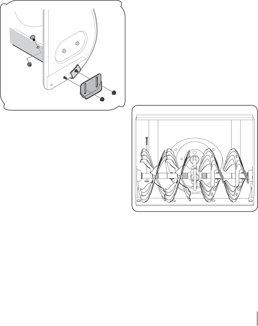
35Sección 6 — ManteniMiento y ajuSteS
Placa de raspado y zapatas antideslizantes
La placa de raspado y las zapatas antideslizantes ubicadas en la base
de la máquina quitanieve están sujetas a desgaste. Debe controlarlas
periódicamente y reemplazarlas cuando sea necesario.
Para reemplazar las zapatas antideslizantes:
1. Retire los pernos del carro y tuercas que sujetan cada zapata
antideslizante a la caja de la barrena. Vea la Figura 6-3.
NOTE: Augers not shown for clarity.
Figura 6-3
2. Vuelva a ensamblar nuevas zapatas antideslizantes con los
elementos de ferretería que acaba de retirar. Compruebe que las
zapatas antideslizantes están ajustadas para que queden parejas.
3. Nota: Consulte la sección Montaje y Configuración para obtener
información sobre el ajuste de las zapatas antideslizantes.
Para retirar la placa de raspado:
1. Retire ambas zapatas antideslizantes y los elementos de
ferretería, incluyendo los pernos del carro y las tuercas que unen
la placa de raspado a la caja de la máquina quitanieve. Para ver
la ubicación de la placa de raspado, consulte la figura 6-3.
2. Vuelva a ensamblar la placa de raspado nueva, asegurándose
de que las cabezas de los pernos del carro se encuentren del
lado interior de la caja.
3. Vuelva a instalar las zapatas antideslizantes. Ajuste bien.
Almacenamiento fuera de temporada
Si no se va a utilizar el accesorio quitanieve durante 30 días o más, o si
es el final de la temporada de nieve y ya no existe posibilidad de que
nieve, es necesario almacenar el equipo de manera adecuada. Siga las
instrucciones de almacenamiento que se indican a continuación para
garantizar el rendimiento máximo de la máquina quitanieve durante
muchos años más.
1. Almacene el equipo en un área despejada y seca.
2. Si almacena la máquina en un lugar mal ventilado, debe
realizarle un tratamiento antioxidante usando un aceite ligero
o silicona para cubrir la máquina quitanieve.
3. Limpie el exterior del accesorio quitanieve.
Preparación del motor
IMPORTANTE: Consulte el manual del operador de la base de
potencia FLEX™ para obtener las instrucciones completas para el
mantenimiento del motor.
Lubricación
Eje de la barrena
Al menos una vez por temporada, quite los pasadores de cuchilla del
eje de la barrena. Rocíe lubricante en el interior del eje y alrededor de
los separadores y los cojinetes bridados que se encuentran en ambos
extremos del eje.
Vea la Figura 6-4.
Figura 6-4
Ruedas
Retire ambas ruedas al menos una vez cada temporada.
Limpie y recubra los ejes con una grasa para automotores
multiuso antes de volver a colocar las ruedas.
NOTA: Las barrenas no se muestran, para mayor claridad.
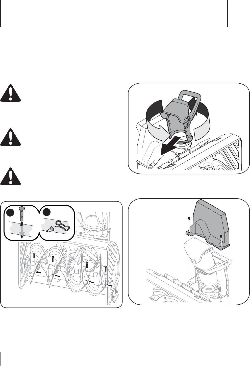
Servicio 7
36
Barrenas
Las barrenas están ajustadas al eje espiral con cuatro pasadores de
cuchilla y pasadores de chaveta. La máquina quitanieve está diseñada
de manera que los pasadores se quiebran si golpea un objeto extraño
o una barra de hielo.
Si las barrenas no giran, verifique si los pasadores se quebraron.
Si es necesario, reemplácelos por pasadores de cuchilla adecuados.
Consulte el número de pieza correcto en la lista de piezas.
PRECAUCIÓN: No reemplace NUNCA los pasadores
de cuchilla por pasadores o sujetadores estándar.
Cualquier daño que sufra el engranaje de la barrena o
cualquier otro componente por el uso de pasadores
estándar NO estará cubierto por la garantía del
accesorio quitanieve.
Reemplazo de los pasadores de cuchilla
PRECAUCIÓN:
NUNCA cambie los pasadores de cu-
chilla de las barrenas por otra cosa que los pasadores de
cuchilla de repuesto del fabricante del equipo original,
Nº de pieza 738-04124A y los pasadores de chaveta con
unión curva 714-04040. Cualquier daño que sufra la caja
de engranajes de la barrena o cualquier otro componen-
te por no respetar la indicación precedente, NO estará
cubierto por la garantía del accesorio quitanieve.
¡ADVERTENCIA! Siempre debe apagar el motor del
accesorio quitanieve, como se indica en el manual del
propietario del motor y retirar la llave antes de cambiar
los pasadores de cuchilla.
1. Reemplace los pasadores de cuchilla como se indica la Figura 7-1.
12
Figura 7-1
Nota: Con este accesorio se incluyeron dos pasadores de
cuchilla de repuesto y pasadores de chaveta con unión curva.
Cambio de la correa de la barrena
2. Desacople el accesorio quitanieve FLEX™ de la unidad base
FLEX™ usando el soporte e inclinando la unidad base hacia
adelante. Mueva con cuidado la unidad base hacia atrás
alejándola del accesorio quitanieve.
3. Estacione la unidad base FLEX™ en un lugar seguro y estable.
4. Gire el canal de descarga hacia la derecha como se muestra
en la Figura 7-2.
Figura 7-2
3. Extraiga los dos tornillos autorroscantes que se muestran en
la Figura 7-3 y levante la cubierta de la correa alejándola del
dispositivo. Deje la cubierta y los tornillos apartados y guárdelos.
Figura 7-3

37Sección 7 — Servicio
4. Incline con cuidado el accesorio quitanieve FLEX™ hacia
adelante sobre el frente de la caja de la barrena como se indica.
Use la manija de montaje que se indicó en la Figura 7-4 para
inclinar esta unidad hacia adelante. NUNCA use la manija del
canal para inclinar esta unidad hacia adelante, para levantarla
ni para ninguna otra función que no sea girar el canal de
descarga a la izquierda o la derecha.
Mounting Handle
Figura 7-4
5. Extraiga el perno de reborde y la tuerca de seguridad
del guardacorrea y guárdelos para volver a colocarlos
posteriormente. Consulte la Figura 7-5.
Figura 7-5
6. Tire de la polea loca hacia afuera (1 en la Figura 7-6) para aflojar
la tensión de la correa de la barrena.
7. Haga rodar la correa para que salga de la polea de barrena
grande, como se indica en 2 de la Figura 7-6, luego sáquela
de la polea superior.
Nota: Al reinstalar la nueva correa, asegúrese de que pase
por el INTERIOR de la polea loca, como se indica en 1 de la
Figura 7-6.
2
1
Figura 7-6
8. Vuelva a instalar el perno con reborde guardacorrea, luego
incline la unidad hacia arriba usando la Manija de montaje,
como se detalla en , luego vuelva a colocar la cubierta de la
correa con los dos tornillos roscados que se habían extraído.
Manija de
montaje

Solución De Problemas 8
38
Problema Causa Remedio
La vibración excesiva o
ruido cuando se aplica el
Anexo palanca de control.
1. Uno o más de los topes de embrague falta o
desgastado.
2. Las partes flojas o la barrena está dañada.
1. Vuelva a colocar los tres topes de embrague
con el reemplazo kit ref. 753 a 08.457.
2. Detenga el motor de inmediato y desconecte
el cable de la bujía. Compruebe por los
posibles daños. Apriete todos los tornillos
y tuercas. Repare según sea necesario. Si
el problema persiste, lleve la unidad a un
distribuidor de servicio autorizado.
Sinfines continúan girando 1. Cable de ajuste. 1. Ajuste el cable del control de la barrena
como se muestra en la sección de
Mantenimiento en “Ajuste del cable de la
unidad de la barrena”.
La unidad no descarga la
nieve
1. Montaje del canal obstruido.
2. Pin (s) Shear esquilada.
3. Objeto extraño en la barrena.
4. Cable de control de la barrena necesita un
ajuste.
5. Auger correa floja o dañada.
1. Detenga el motor y desconecte el cable de la
bujía. Limpie el canal y en el interior de la caja
de la barrena con la herramienta de limpieza
o una varilla de salida.
2. Reemplace pasador de seguridad (s).
3. Detenga el motor de inmediato y desconecte
el cable de la bujía. Retire el objeto de la
barrena.
4. Ajuste el cable de control de la barrena.
5. Cambie la correa de la barrena.
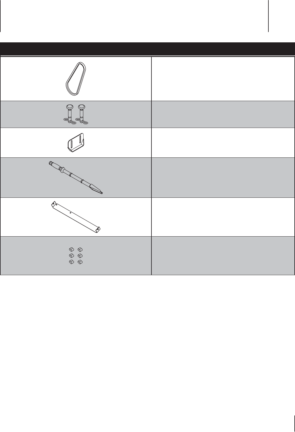
Componente Número de pieza y Descripción
954-05071 Auger correa de transmisión
738-04124A Shear Pin, 1.50
714-04040 Pajarita Chaveta
784-5580 Zapato Skid, Standard (acero)
931-2643 Herramienta de limpieza del canal de
salida
790-00121 Placa Shave
753-08457 Pegatina Kit de embrague (6)
Teléfono (800) 828-5500 para solicitar piezas de reemplazo o un Manual de Repuestos completo (tenga el número de modelo y
número de serie). Piezas descargas manuales también están disponibles de forma gratuita en www.troybilt.com.
Piezas de reemplazo 9
39

GARANTÍA LIMITADA PARA EL ACCESORIO FLEX
079221 REV. A
5. Los artículos desechables, consumibles o de mantenimiento de
rutina que requieren reparaciones o mantenimiento como parte
del mantenimiento normal, a menos que tales artículos presenten
defectos que ocasionen fallas o un desgaste prematuro dentro de los
primeros treinta (30) días. De corresponder, los artículos de desgaste
normal incluyen, a título de ejemplo, las cuchillas, los neumáticos, las
correas, los filtros, los fusibles y otros artículos consumibles
6. Cualquier Accesorio que haya sido alterado o modificado de una manera
que no sea coherente con el diseño original del producto o de una manera
no aprobada de alguna otra manera por Troy-Bilt LLC.
7. Las reparaciones en concepto de pintura o los reemplazos por defectos en
la pintura (que incluyen los materiales y la aplicación) están cubiertos por
un período de tres (3) meses.
8. Las llantas de ruedas están cubiertas por un período de tres (3) meses por
defectos de fabricación.
9. La la base de potencia FLEX está cubierta por una garantía limitada
separada que se incluye en el manual del operador de la base de potencia
FLEX.
La presente garantía no cubre y Troy-Bilt LLC rechaza todo tipo de
responsabilidad en concepto de:
1. Pérdida de tiempo o pérdida de uso del Accesorio.
2. Costos de transporte y otros gastos incurridos en relación con el
transporte del Accesorio desde y hacia el proveedor de reparaciones
y mantenimiento Troy-Bilt autorizado.
3. Cualquier pérdida o daño a otros equipos o efectos personales.
4. Daños ocasionados por el rendimiento o el uso del Accesorio con
cualquier producto que no sea la Base de potencia Flex.
Limitaciones:
1. NO EXISTEN GARANTÍAS IMPLÍCITAS, ENTRE LAS QUE SE INCLUYEN,
A TÍTULO DE EJEMPLO, LAS GARANTÍAS IMPLÍCITAS DE COMERCIABILIDAD
O ADECUACIÓN PARA UN PROPÓSITO EN PARTICULAR. NO SE
APLICA NINGUNA GARANTÍA AL CABO DEL PERÍODO DE GARANTÍA
CORRESPONDIENTE SEGÚN LO ESTABLECIDO PRECEDENTEMENTE EN
RELACIÓN CON LAS PIEZAS DE ACUERDO CON SU IDENTIFICACIÓN.
NINGUNA OTRA GARANTÍA EXPRESA, YA SEA ORAL O ESCRITA, EXCEPTO
LA MENCIONADA ANTERIORMENTE, EXTENDIDA POR PERSONAS FÍSICAS O
JURÍDICAS, INCLUIDOS LOS DISTRIBUIDORES O MINORISTAS CON RESPECTO
A LOS PRODUCTOS, OBLIGARÁ A TROY-BILT LLC. DURANTE EL PLAZO DE
LA GARANTÍA, EL ÚNICO RECURSO ES LA REPARACIÓN O EL REEMPLAZO
DE LA PIEZA DEFECTUOSA, COMO SE INDICÓ ANTERIORMENTE. (ALGUNOS
ESTADOS NO PERMITEN LAS LIMITACIONES DE LA DURACIÓN DE LAS
GARANTÍAS IMPLÍCITAS, POR LO QUE LA LIMITACIÓN ANTES MENCIONADA
PUEDE NO SER DE APLICACIÓN EN SU CASO).
2. LAS DISPOSICIONES ESTABLECIDAS EN EL PRESENTE DOCUMENTO
PREVÉN EL ÚNCIO Y EXCLUSIVO RECURSO QUE SURGE DE LA VENTA.
TROY-BILT NO SE HARÁ RESPONSABLE DE LAS PÉRDIDAS O LOS DAÑOS
INDIRECTOS O EMERGENTES, INCLUIDOS SIN LIMITACIÓN, LOS GASTOS
DE TRANSPORTE O LOS GASTOS RELACIONADOS, NI DE LOS GASTOS
DE ARRENDAMIENTO PARA REEMPLAZAR TRANSITORIAMENTE UN
PRODUCTO CUBIERTO POR LA GARANTÍA. (ALGUNOS ESTADOS NO
PERMITEN LA EXCLUSIÓN O LIMITACIÓN DE LOS DAÑOS Y PERJUICIOS
INCIDENTALES O DIRECTOS, POR LO QUE LAS EXCLUSIONES O
LIMITACIONES MENCIONADAS ANTERIORMENTE PUEDEN NO SER DE
APLICACIÓN EN SU CASO).
3. En ningún caso se obtendrá una compensación mayor al monto del precio
de compra del producto adquirido. La alteración de las características de
seguridad del producto anulará esta garantía limitada. Usted asume el
riesgo y la responsabilidad por las pérdidas, daños o lesiones que sufran
Usted y sus bienes y/u otras personas y sus bienes como consecuencia del
uso, del uso incorrecto o de la imposibilidad de uso de este producto.
Relación de la ley estadual con esta garantía:
Esta garantía limitada le otorga derechos legales específicos, pero usted podría
gozar de otros derechos que varían en razón de su lugar de residencia.
Troy-Bilt LLC, P.O. BOX 361131 CLEVELAND, OHIO 44136-0019; Teléfono: 1-800-828-5500, 1-330-558-7220
MTD Canada Limited - KITCHENER, ON N2G 4J1; Teléfono 1-800-668-1238
La garantía limitada que se estable en el presente documento es otorgada
por Troy-Bilt LLC al comprador inicial (como se define en este documento)
en relación con el nuevo accesorio FLEX Troy-Bilt que está integrado por uno
de los siguientes cuatro (4) accesorios de la base de potencia FLEX (identificado
en adelante como el "Accesorio"): (i) cortadora de césped con capacidad para
superficies amplias, (ii) máquina quitanieve, (iii) lavadora a presión
o (iv) soplador de hojas. La presente garantía limitada no cubre los Sistemas
de control de emisiones y no constituye una Declaración de garantía del control
de las emisiones federal según lo definido por las leyes federales de los Estados
Unidos. Consulte la Declaración de garantía del control de las emisiones federal
que se incluye en el manual del operador de la base de potencia FLEX
("Base de potencia") para conocer las garantías que cubren los Sistemas
de control de emisiones.
Alcance de la Garantía limitada
Troy-Bilt LLC ofrece la siguiente garantía limitada al Comprador Inicial para uso
residencial u otro tipo de uso no comercial del accesorio de la base de potencia
FLEX: excepto por las Exclusiones (que se definen en el presente documento),
durante el Período de la Garantía (como se define en este documento), el
Accesorio estará libre de defectos de fabricación (que incluyen la mano de obra y
los materiales). El “Comprador inicial” es la primera persona en adquirir un nuevo
Accesorio a un representante, distribuidor y/o minorista Troy-Bilt autorizado
del mencionado accesorio. La garantía limitada es intransferible. Excepto que
se disponga lo contrario en el presente documento, el período de la garantía
limitada para este nuevo Accesorio adquirido por el Comprador inicial es de dos
(2) años a partir de la fecha de la compra, como se indica en el comprobante de
ventas original correspondiente al Accesorio (“Período de la Garantía”).
Defectos en la mano de obra o en los materiales
Excepto por las Exclusiones, se garantiza que el Accesorio estará libre de defectos
de fabricación en la mano de obra o los materiales durante el Período de la Garantía.
Durante el Período de la Garantía, Troy-Bilt LLC reparará o reemplazará, a su juicio,
cualquier pieza original que esté cubierta por la presente garantía limitada y que se
determine que presenta algún defecto en la mano de obra o los materiales.
A fin de reunir los requisitos para la presente garantía limitada, la Unidad
Base FLEX™:
1. Debe haberse adquirido a un minorista Troy-Bilt autorizado.
2. Debe haberla adquirido el Comprador inicial dentro del territorio de
los Estados Unidos.
3. Debe haberse usado únicamente para fines residenciales u otro tipo
de uso no comercial.
4. Debe haberse usado de una manera coherente con el uso normal y
adecuado para el que fue diseñado el Accesorio. El Accesorio no está
diseñado para arrendamiento ni para uso comercial.
¿Quién puede realizar reparaciones en virtud de la presente garantía?
A fin de reunir los requisitos para la garantía limitada según lo establecido en
el presente documento, las reparaciones realizadas en virtud de esta garantía
debe llevarlas a cabo un proveedor de reparaciones y mantenimiento Troy-Bilt
autorizado.
Procedimiento para obtener reparaciones o mantenimiento en virtud
de la presente garantía limitada:
A fin de ubicar a un proveedor de reparaciones y mantenimiento de la garantía
Troy-Bilt, comuníquese con el representante, distribuidor y/o minorista Troy-Bilt
autorizado o comuníquese con Troy-Bilt LLC por correo escribiendo a P.O.
Box 361131, Cleveland, Ohio 44136-0019 o telefónicamente llamando al
1-877-282-8684 o inicie sesión en nuestro sitio Web en www.troybilt.com.
La presente garantía limitada sobre un producto es otorgada por Troy-Bilt LLC
y es la única garantía de producto que otorga Troy-Bilt LLC para este Accesorio.
SE REQUIERE UNA COPIA DEL COMPROBANTE DE VENTAS PARA LAS TAREAS
DE REPARACIÓN Y MANTENIMIENTO CUBIERTAS POR LA GARANTÍA
Lo que no cubre la presente garantía limitada.
La presente garantía limitada no cubre lo siguiente (las “Exclusiones”):
1. Los Accesorios adquiridos fuera del territorio de los Estados Unidos.
2. Los daños producidos por la falta de mantenimiento y/o un
mantenimiento inadecuado, según se describe en el manual del operador.
3. El desgaste normal producto del uso del Accesorio.
4. El uso del Accesorio que no sea coherente con el uso para el que fue
diseñado según se describe en las instrucciones de funcionamiento, que
incluye, a título de ejemplo, el uso abusivo, inadecuado y/o negligente del
Accesorio o cualquier uso que no sea coherente con las instrucciones que
se incluyen en el Manual del Operador y/o no cumpla con ellas.
