u blox Malmo 0926 Wireless Communication System Module User Manual Host
u-blox Malmo AB Wireless Communication System Module Users Manual Host
Contents
- 1. Users Manual Host
- 2. Users Manual HOST
Users Manual Host

connectBlue
Copyright © 2010 connectBlue AB Page 1 of 21
PRODUCT GUIDE - WLAN EPA
This is a draft version of the document
Document Revision
Release: 26 aug, 2010 08:15
Document version: 107
Copyright © 2010 connectBlue AB. The contents of this document can be changed by connectBlue AB without prior notice and do not
constitute any binding undertakings from connectBlue AB. connectBlue AB is not responsible under any circumstances for direct, indirect,
unexpected damage or consequent damage that is caused by this document. All rights reserved. All brand and product names are
trademarks or service marks of their respective owners.

connectBlue
Copyright © 2010 connectBlue AB Page 2 of 21
1 Abstract
This document is a product guide defining the main use cases for the connectBlue WLAN Ethernet Port Adapter (later called WEPA) and
how to configure the specific use cases. I also contains general information about the product.
2 Table of Content
1 Abstract
2 Table of Content
3 Related Documents
4 Installation
4.1 Connectors
4.2 Antenna alignment and range optimizations
4.3 Status indicators
5 General Concepts
5.1 Configuration Methods
5.2 Using the SMART configuration mode
5.3 Using the WEB configuration
5.4 Reset to factory defaults
5.5 Wireless LAN Modes
5.6 WEPA Modes
5.7 WLAN Security
6 Supported Use Cases
6.1 Two WEPAs Connected as an Ethernet Bridge - Alternative 1
6.2 Two WEPAs Connected as an Ethernet Bridge - Alternative 2
6.3 Two WEPAs Connected as an Ethernet Bridge - Alternative 3
6.4 Two WEPAs Connected in External Wireless Mode - Alternative 1
6.5 Two WEPAs Connected in External Wireless Mode - Alternative 2
6.6 A PC wirelessly connected to a WEPA - Alternative 1
6.7 A PC wirelessly connected to a WEPA - Alternative 2
6.8 Several Ethernet devices connected in External Wireless Mode - Alternative 1
6.9 Several Ethernet devices connected in External Wireless Mode - Alternative 2
6.10 One or more WEPAs connected to a Wired Infrastructure through WLAN
6.11 External WLAN client connected to a WEPA
7 Currently Unsupported Use Cases
7.1 External device connected to WEPA connected to a Ethernet infrastructure
8 Legal and Regulatory
8.1 IC and FCC compliance
8.2 Declaration of Conformity
8.3 Licenses
3 Related Documents
Quick Setup Guide - WLAN EPA. A quick setup guide to be able to quickly setup the WEPA for the simplest use cases
out-off-the-box.
AT Command Specification - WLAN EPA. Detailed specification/reference for all of the supported AT commands.
connectBlue
Copyright © 2010 connectBlue AB Page 3 of 21
1.
2.
3.
4.
5.
1.
2.
3.
4.
4 Installation
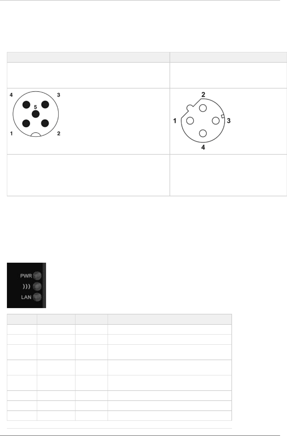
4.1 Connectors
Power connector Ethernet connector
The power connector has both a supply power input and a digital input with
separate ground. Both the power supply input and digital input support a
voltage of 9-30V. The connector is an A-coded male M12.
The Ethernet interface supports 10/100 Mbps with both
MDI/MDI-X auto crossover and polarity correction. The
connector is a D-coded female M12.
Vin + (9-30V)
Digital Input Ground
Vin Ground
Digital Input + (9-30V)
N/C (May be used for shield ground)
Transmit +
Receive +
Transmit -
Receive -
4.2 Antenna alignment and range optimizations
For range critical applications, the positioning of the WEPAs are very important. For best range, the EPAs should be placed in line of
sight and facing each other. For long distances or if the WEPAs are placed in bad radio environments, the range could be increased by
slightly rotating the WEPAs. The best theoretical range is achived when the WEPAs are tilted 345 degrees internally, i.e one is rotated
345 degrees and the other is 0 degrees or both are rotated 352.5 degrees.
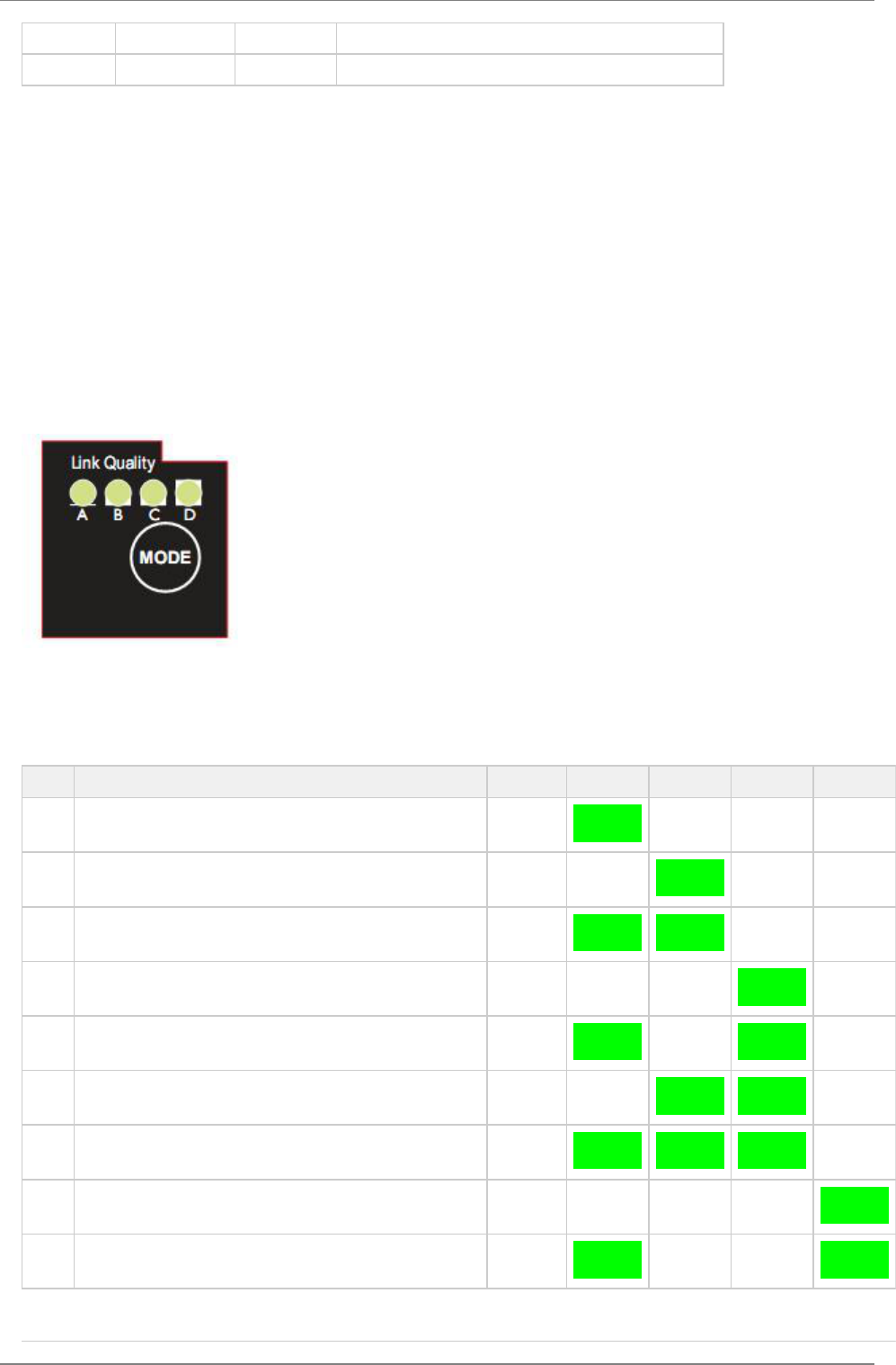
4.3 Status indicators
Description Color Status Meaning
PWR Green On Supply voltage is present and application is running
PWR Green Off Supply voltage is not present, or no application is running
))) Blue/Purple/Red Blue A WLAN connection has been established
))) Blue/Purple/Red Flashing Blue WLAN data activity
))) Blue/Purple/Red Purple Attempt to establish a connection to another WLAN device
))) Blue/Purple/Red Red Error
))) Blue/Purple/Red Off No WLAN activity
LAN Yellow On Ethernet link is present
connectBlue
Copyright © 2010 connectBlue AB Page 4 of 21
1.
2.
3.
4.
LAN Yellow Flashing Ethernet data activity
LAN Yellow Off No Ethernet connection
5 General Concepts
5.1 Configuration Methods
The WEPA supports four main conceps for setting and configuring the WEPA:
SMART mode. Use the buttons and LEDs on the WEPA to setup the most common use cases automatically.
Web interface. A online WEB interface with the most common manual settings for the WEPA.
AT commands. Connect to the WEPA over Ethernet using TCP or direct on Layer 2 and use a terminal like Hyperterminal to
issue AT commands. This method is mainly for more advanced settings and use cases and will not be used in this document. All
you can do in the Web interface and much more is supported using the AT commands.
The SNMP protocol. This will not be used and described in this document.
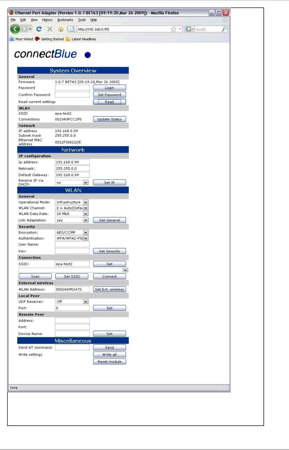
5.2 Using the SMART configuration mode
If the mode button is pressed within the 5 seconds from power up, the WEPA will enter the SMART configuration mode. The LEDs above
the button (marked A, B, C and D) will show which mode is selected. When the preferred mode is selected it must be confirmed by
holding the SMART button for two seconds. This will cause the LEDs to start flashing during the operation of the selected mode.
There are currently 12 different modes:
Mode Description LEDs A B C D
1 Enable DHCP server A
2 Reset to factory defaults. This will reset the configuration to
factory defaults
B
3 Reset IP settings to factory defaults. This will only reset the IP
settings to factory defaults
A + B
4 Wait for Automatic configuration, Ad-Hoc mode C
5 Initiate Automatic configuration, Ad-Hoc mode A + C
6 Wait for Automatic configuration with Profinet optimizations,
Ad-Hoc mode
B + C
7 Initiate Automatic configuration with Profinet optimizations,
Ad-Hoc mode
A + B + C
8 Wait for Automatic configuration, Managed mode D
9 Initiate Automatic configuration, Managed mode A + D

connectBlue
Copyright © 2010 connectBlue AB Page 5 of 21
10 Initiate Automatic configuration, Managed mode, wired B + D
11 Configure external wireless A + B + D
12 Initiate Automatic configuration, Ad-Hoc mode, multipoint C + D
13 Reserved for future use A + C + D
14 Reservedfor future use B + C + D
15 Reservedfor future use A + B + C
+ D
The "Enable DHCP server" can be used to easily access the WEPA if the PC is using DHCP without having to change the PC IP settings.
This mode should only be used when the PC is directly connected to the WEPA and not if the WEPA is connected to a network where
there already exists a DHCP server. Enable this mode, then connect the Ethernet cable to the computer. The DHCP server will be
enabled until a reboot of the WEPA and in version 1.2.1 the LEDs will not blink during the operation of this mode!
Later we will describe how to use the other different modes for a specific use case.
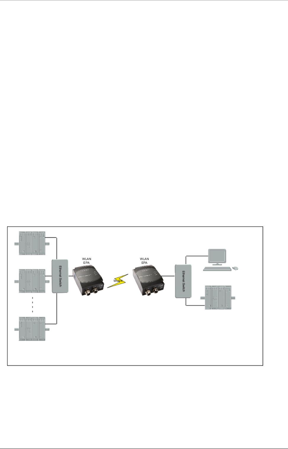
5.3 Using the WEB configuration
By default the WEPA has static IP settings which are; IP address: 192.168.0.99, subnet mask: 255.255.0.0 and default gateway:
192.168.0.99. To access the WEPA by the Web based configuration interface the computer must be set up in the same network, e.g. IP
address: 192.168.0.1 and subnet mask: 255.255.0.0.
Open a web browser and enter in the address bar. Here you'll find the most common configuration parametershttp://192.168.0.99
needed to setup a connection. If the device is in factory default, you will not need to login before configuring the unit.
Below is an example of the WEB interface shown.
connectBlue
Copyright © 2010 connectBlue AB Page 6 of 21

connectBlue
Copyright © 2010 connectBlue AB Page 7 of 21
1.
2.
3.
1.
2.
1.
2.
5.4 Reset to factory defaults
It is possible to reset to factory settings in 3 different ways.
Enter and confirm SMART mode 2.
Issue AT&F.
Holding the mode button while the WEPA is starting. Note! Make sure that the Ethernet cable is disconnected or that any
firmware update program is stopped.
5.5 Wireless LAN Modes
A Wireless LAN network can be set up in two main connection modes:
AD-Hoc Mode. This is typically used when two WLAN devices is connected to each without going through a WLAN Access
Point. In Ad-Hoc Mode is only 802.11b transmission speeds used. This means a maximum of 11 Mbit/s. The only encryption
method that can be used is WEP encryption.
Managed (or Infrastucture Mode). This is typically used when a group of devices is connected through a common WLAN
Access Point. In this mode, all available transmission speeds can be used up to a maximun of 54 Mbit/s. This also allows for
user selection of which encryption and authentication methods to use.
This means that use cases that supports Managed mode has normally a higher througput.
5.6 WEPA Modes
There are two main "WEPA modes" supported by the WEPA and they will be referred to in all the use cases described later in this
document.
Ethernet Bridge Mode. This mode is supported between two WEPAs only. In this mode the Ethernet packages is encapsulated
into UDP packages and transferred transparently between the two WEPAs. Devices on both sides off the wireless link is
completely unaware of the wireless connection.
External Wireless Mode. In this mode the WEPA is acting as a wireless extension of the wired Ethernet device it is connected
to. The WEPA is configured to take over (clone!)the MAC address of the connected device. This means that EthernetONE
device can only be connected to each WEPA, not a Ethernet network with several devices connected through a Ethernet switch
or hub.
Ethernet Bridged Mode will introduce an extra overhead (because of the encapsulation) and will have a significant lower throughput than
External Wireless Mode.
5.7 WLAN Security
The WEPA supports different authentication and encryption methods. The following authentication methods are supported:
Open connection
Shared secret
WPA and WPA2 Pre-shared key
LEAP
PEAP
The Following encryption methods are supported:
No encryption
WEP64
WEP128
TKIP
AES/CCMP
The following table shows valid combinations of authentication and encryption methods (x means valid configuration):
Open connection Shared secret WPA/WPA2 PSK LEAP PEAP
No encryption x
WEP 64 x x x
WEP 128 x x x
TKIP x (WPA) x x
AES/CCMP x (WPA2) x x
There are a few important considerations that need to be addressed as well. If you choose WPA/WPA2 PSK and TKIP, this is considered
connectBlue
Copyright © 2010 connectBlue AB Page 8 of 21
1.
2.
3.
4.
a WPA connection. If you choose WPA/WPA2 PSK and AES/CCMP, a WPA2 connection is assumed. It is not possible to have WPA with
AES/CCMP encryption.
If you wish to use LEAP or PEAP as the authentication algorithm, make sure that your access point supports it. Not all access points
support LEAP/PEAP. Neither LEAP, PEAP nor WPA/WPA2 PSK will work in ad-hoc mode.
Note: Some access points have support for a combination of WPA and WPA2 as well as AES/CCMP and TKIP. These options are not
supported by the WEPA!
5.7.1 Key management
For WEP64 and WEP128 shared keys can be entered into all four possible slots made available by the AT*AGFPWI Write
Encryption/Authentication Key (with Index) command. However, for LEAP, PEAP and WPA/WPA2 PSK the password or PSK must be
entered into key slot with index 1 (one). This key must also be the one currently set active by the AT*AGAFP Active
Encryption/Authentication Key command.
If you are using LEAP or PEAP, the username for the Radius server should be entered with the command AT*AGUN Username and the
domain with command AT*AGDN. For PEAP, the certificate must also be considered. When receiving the certificate from the Radius
server, the SHA-1 fingerprint is calculated and stored in the WEPA for future comparisons. If the certificate changes, or you want to use a
different Radius server, the new fingerprint must be entered or the old must be cleared with the command AT*AGCFP.
If you are using WPA/WPA2 PSK you can enter either the pre-shared key (i.e. the hexadecimal string) or the password (plain-text),
commonly referred to as “WPA-PSK” and “WPA-PWD”. If you choose to enter a password (not a hexadecimal string) the WEPA will take
a few seconds longer during the next connection after this change, in order to deduce the real key from the password. While the WEPA is
calculating the real key it will be unresponsive.
By default, the key is entered as ASCII string. To enter a hexadecimal key, the bytes needs to be escaped with a '\' character, e.g. to
enter the string "12345" as hexadecimal, "\31\32\33\34\35" should be entered.
6 Supported Use Cases
6.1 Two WEPAs Connected as an Ethernet Bridge - Alternative 1
6.1.1 Overview
This use case is using two WEPAs connected in Ethernet Bridge Mode. This use case support several Ethernet devices on each side of
the WEPA. The Ethernet data is bridged through an UDP tunnel and can be used both in Ad-Hoc mode only.
6.1.2 How to setup this use case?
This use case can be set up by using the SMART button:
Power on the first device and enter SMART configuration mode 4
Power on the second device and enter SMART configuration mode 5
Wait for the devices to connect and restart.
Now, the first device will have IP address 192.168.0.99 and the second 192.168.0.100 and the devices will operate in AdHoc
mode.
connectBlue
Copyright © 2010 connectBlue AB Page 9 of 21
1.
2.
3.
4.
5.
6.
7.
8.
9.
10.
11.
12.
13.
14.
15.
1.
2.
3.
4.
In case of the predefined IP addresses are already in use on your network it might be necessary to configure the setup manually:
Power on the first WEPA and enter the WEB configuration, see "Using the WEB configuration".
Enter desired IP Address ( ), Netmask and Default Gateway, press "Set IP". The IP address must be selectedIP_ADDR1 NOTE:
to avoid IP conflicts.
Choose Operational mode "Ad-Hoc" and select a channel you want to use based on your regional domain settings, press "Set
General".
Select encryption; "None", "WEP64" or "WEP128" are currently possible to use in Ad-Hoc.
Select Authentication; "Open" and "Shared" is currently possible to use in Ad-Hoc.
Enter a key to use for the security. User Name can be left blank, press "Set Security".
Enter SSID for your network and press "Set".
Under local peer, UDP receiver SHALL be set to on and a port must be selected, if you don't have any specific requirements,
enter 7 and press "Set".
Under Remote peer, enter the address and port you intend to use on the second WEPA ( ). Make sure they are in theIP_ADDR2
same subnet. Device name can be left blank. Press "Set" and reboot the WEPA
Power on the second WEPA and enter the WEB configuration.
Enter desired IP address ( ). This SHALL be the same as entered under Remote peer above. Enter Netmask andIP_ADDR2
Default Gateway. Press Set IP.
Choose Operational mode "Ad-Hoc" and select the same channel as chosen above. Press "Set General".
Repeat 4, 5, 6 and 7 above. These values SHALL be identical as entered in the previous WEPA.
Under local peer, UDP receiver SHALL be set to on and the port must be the same as was entered under 9 above, press "Set"
Under Remote peer, enter the IP address of the first WEPA ( and the port selected under 8 above. Press "Set" andIP_ADDR1)
reboot the WEPA.
Now, all Ethernet packets will be tunneled between the two Ethernet segments.
6.2 Two WEPAs Connected as an Ethernet Bridge - Alternative 2
6.2.1 Overview
This use case is using two WEPAs connected in Ethernet Bridge Mode. This use case support several Ethernet devices on each side of
the WEPA. The Ethernet data is bridged through an UDP tunnel and can be used both in Managed (Infrastructure) mode.
6.2.2 How to setup this use case?
This use case can be set up by using the SMART button:
To use the Automatic configuration in Managed mode, the SSID and security parameters (Encryption, Authentication, User Name and
Key) must be configured manually (using the Web interface or AT commands), unless you want to use the default values. For more
information on the Web interface see section " ".Using the WEB configuration
Power on the first device and enter SMART configuration mode 8
Power on the second device and enter SMART configuration mode 9
Wait for the devices to connect and restart.
Now, the first device will have IP address 192.168.0.99 and the second 192.168.0.100 and the devices will operate in Managed
mode.
connectBlue
Copyright © 2010 connectBlue AB Page 10 of 21
1.
2.
3.
4.
6.3 Two WEPAs Connected as an Ethernet Bridge - Alternative 3
6.3.1 Overview
This use case is using two WEPAs connected in Ethernet Bridge Mode. In this case is one of the WEPAs connected to a wired network
and does NOT use the wireless connection. This case is only possible to use in Managed (Infrastructure) mode.
6.3.2 How to setup this use case?
This use case can be set up by the SMART button:
To use the Automatic configuration in Managed mode, the SSID and security parameters (Encryption, Authentication, User Name and
Key) must be configured manually (using the Web interface or AT commands), unless you want to use the default values. For more
information on the Web interface see section " ".Using the WEB configuration
Power on the first device and enter SMART configuration mode 8
Power on the second device (the one on the wired network) and enter SMART configuration mode 10
Wait for the devices to connect and restart.
Now, the first device will have IP address 192.168.0.99 and the second 192.168.0.100 and the devices will operate in Managed
mode.
6.4 Two WEPAs Connected in External Wireless Mode - Alternative 1
6.4.1 Overview
This use case is using two WEPAs connected in External Wireless Mode. This use case supports one Ethernet device only connected to
each of the WEPAs. This use case will have higher performance than using the Ethernet Bridging case (no encapsulation of the Ethernet
packages are required).
connectBlue
Copyright © 2010 connectBlue AB Page 11 of 21
1.
2.
3.
4.
1.
2.
6.4.2 How to setup this use case?
This use case can be set up by using the SMART button and will support Ad-Hoc mode only:
Power on the first device and enter SMART configuration mode 4
Power on the second device and enter SMART configuration mode 5
Wait for the devices to connect and restart.
Use SMART mode 11 on each on the devices to learn the MAC address of the connected device (External Wireless Mode).
NOTE! For this mode to operate it is required that the device spontaneously is sending Ethernet data on the Ethernet link.
If this not is possible, use the Web interface, see section " to set up the MAC address manually.Using the WEB configuration,
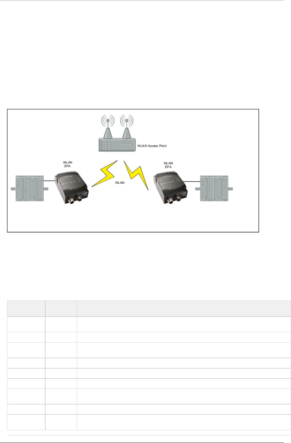
6.5 Two WEPAs Connected in External Wireless Mode - Alternative 2
6.5.1 Overview
This use case is using two WEPAs connected in External Wireless Mode. This use case supports one Ethernet device only connected to
each of the WEPAs. The WEPA is connected to a WLAN Access Point that allow us to use Managed (Infrastructure) Mode with higher
performance as a result.
6.5.2 How to setup this use case?
Both WEPAs must operate in External Wireless Mode in this use case.
Connect a PC to the WEPA. See section for more information on how to connect to a WEPA.Using the WEB configuration
Define the WLAN connection parameters. The following parameters are required:
Parameter Required
Value
Comment
Operational
Mode
Managed
WLAN Channel Select the one used by the the Access Point.
WLAN Data
Rate
This is the maximum used data rate.
Link Adaption Yes or No
Encryption Choose the one required by the Access Point.
Autenthication Choose the one required by the Access Point.
User Name and
Key
Choose the one required by the Access Point.
SSID Choose the SSID of the Access Point.
WLAN Address Enter the MAC address of the device the WEPA is connected to or use SMART to assign the MAC
address (see next bullet).
connectBlue
Copyright © 2010 connectBlue AB Page 12 of 21
1.
1.
2.
1.
UDP Receiver Off
As an alternative to enter the MAC address manually, SMART mode 11 may be used.
NOTE! For this mode to operate it is required that the device spontaneously is sending Ethernet data on the Ethernet link.
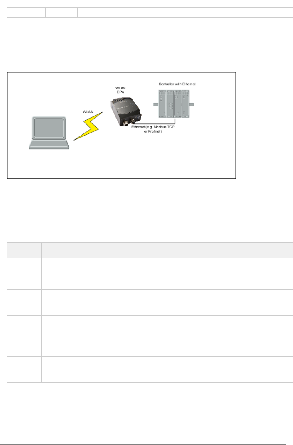
6.6 A PC wirelessly connected to a WEPA - Alternative 1
6.6.1 Overview
In this use case Ethernet device is connected to the WEPA. The PC is used to access the Ethernet device using anyONE
Ethernet-based protocol e.g. a built-in Web interface or using a Ethernet-based communication protocol e.g. Modbus/TCP.
6.6.2 How to setup this use case?
The WEPA must operate in External Wireless Mode in this use case.
Connect a PC to the WEPA. See section " " for more information on how to connect to the WEPA.Using the WEB configuration
Define the WLAN connection parameters. The following parameters are required:
Parameter Required
Value
Comment
Operational
Mode
Ad-Hoc This is the only supported mode in this use case.
WLAN
Channel
Choose one of your own choice.
WLAN Data
Rate
This is the maximum used. As this always is using Ad-Hoc mode is up to 11 MBit/s supported. If higher
rate is chosen it will default to a maximum of 11 MBit/s.
Link Adaption No Link adaption is not supported in Ad-Hoc mode. If Yes is chosen the setting will have no effect.
Encryption WEP WEP is the only supported encryption in Ad-Hoc mod.
Autenthication Open
Key Choose a WEP key of your own choice.
SSID Choose a SSID of your own choice. This is the ID shown to the PC when searching for the WEP.
WLAN
Address
Enter the MAC address of the device the WEPA is connected to or use SMART to assign the MAC
address (see next bullet).
UDP Receiver Off
As an alternative to enter the MAC address manually, SMART mode 11 may be used.
NOTE! For this mode to operate it is required that the device spontaneously is sending Ethernet data on the Ethernet link.
How to setup the PC is dependent on the Wireless LAN solution supported for the PC. Use the WLAN GUI to search for an Ad-Hoc
network with the same SSID as the one set for the WEPA. Select WEP as encryption and select the same WEP key that you entered
during the WEPA configuration.
connectBlue
Copyright © 2010 connectBlue AB Page 13 of 21
1.
2.
1.
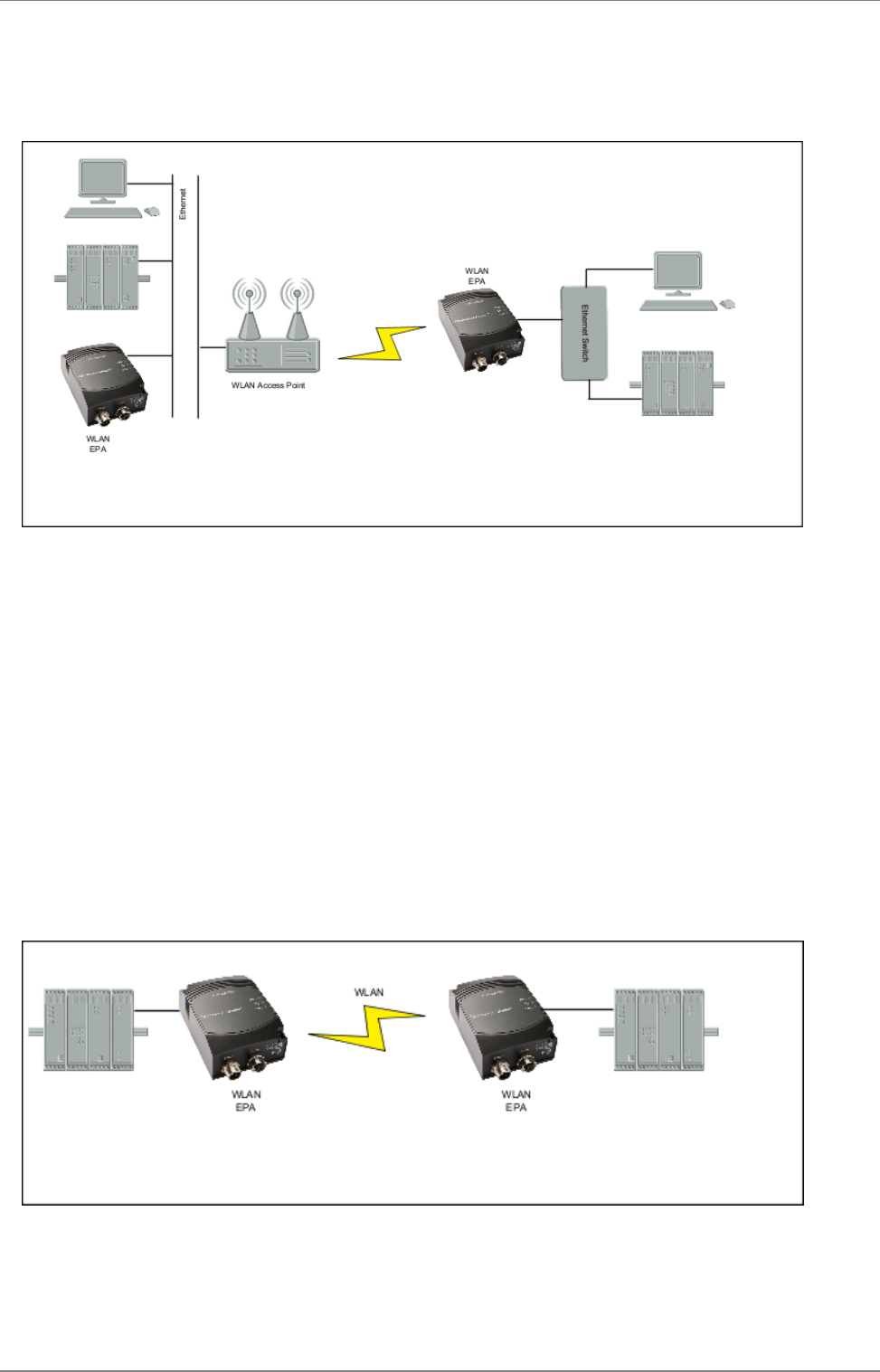
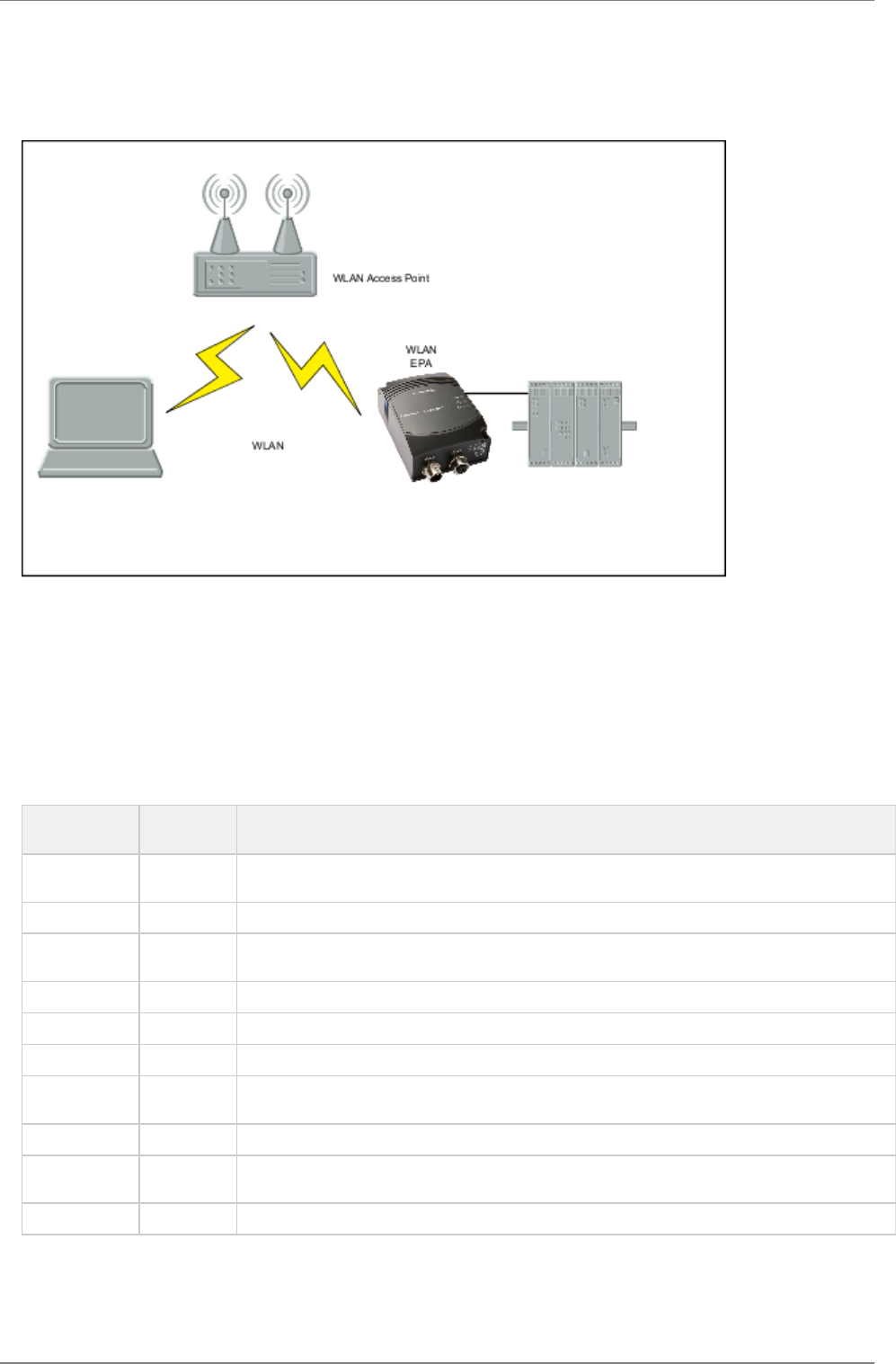
6.7 A PC wirelessly connected to a WEPA - Alternative 2
6.7.1 Overview
In this use case one Ethernet device is connected to the WEPA. The PC is used to access the Ethernet device using any Ethernet-based
protocol e.g. a built-in Web interface or using a Ethernet-based communication protocol e.g. Modbus/TCP. In this case is the WEPA and
the PC connected to each other via a WLAN Access Point that allow us to use Managed (Infrastructure) Mode with higher performance
as a result.
6.7.2 How to setup this use case?
The WEPA must operate in External Wireless Mode in this use case.
Connect a PC to the WEPA. See section for more information on how to connect to a WEPA.Using the WEB configuration
Define the WLAN connection parameters. The following parameters are required:
Parameter Required
Value
Comment
Operational
Mode
Managed
WLAN Channel Select the one used by the the Access Point.
WLAN Data
Rate
This is the maximum used data rate.
Link Adaption Yes or No
Encryption Choose the one required by the Access Point.
Autenthication Choose the one required by the Access Point.
User Name and
Key
Choose the one required by the Access Point.
SSID Choose the SSID of the Access Point.
WLAN Address Enter the MAC address of the device the WEPA is connected to or use SMART to assign the MAC
address (see next bullet).
UDP Receiver Off
As an alternative to enter the MAC address manually, SMART mode 11 may be used.
NOTE! For this mode to operate it is required that the device spontaneously is sending Ethernet data on the Ethernet link.
How to setup the PC is dependent on the Wireless LAN solution supported for the PC. Use the WLAN GUI to search for Managed
(Infrastructure) network with the same SSID as the access point. Select the sane security parameters as defined for the access point.
connectBlue
Copyright © 2010 connectBlue AB Page 14 of 21
1.
2.
1.
6.8 Several Ethernet devices connected in External Wireless Mode - Alternative 1
6.8.1 Overview
Three or more WEPAs connected in a Ad-Hoc network. This use case requires External Wireless Mode.
6.8.2 How to setup this use case?
All WEPAs must operate in External Wireless Mode in this use case.
Connect a PC to each of WEPAs. See section for more information on how to connect to a WEPA.Using the WEB configuration
Define the WLAN connection parameters. The following parameters are required:
Parameter Required
Value
Comment
Operational
Mode
Ad-Hoc This is the only supported mode in this use case.
WLAN
Channel
Choose one of your own choice. Select the same on all WEPA.
WLAN Data
Rate
This is the maximum used. As this always is using Ad-Hoc mode is up to 11 MBit/s supported. It is
recommended to have the same settings on all WEPAs. If higher rate is chosen it will default to a
maximum of 11 MBit/.
Link Adaption No Link adaption is not supported in Ad-Hoc mode. If yes is chosen this setting will have no effect.
Encryption WEP WEP is the only supported encryption in Ad-Hoc mod.
Autenthication Open
Key Choose a WEP key of your own choice.
SSID Choose a SSID of your own choice. Use the same SSID on all WEPAs.
WLAN
Address
Enter the MAC address of the device the WEPA is connected to or use SMART to assign the MAC
address (see next bullet).
UDP Receiver Off
As an alternative to enter the MAC address manually, SMART mode 11 may be used.
NOTE! For this mode to operate it is required that the device spontaneously is sending Ethernet data on the Ethernet link.
connectBlue
Copyright © 2010 connectBlue AB Page 15 of 21
1.
2.
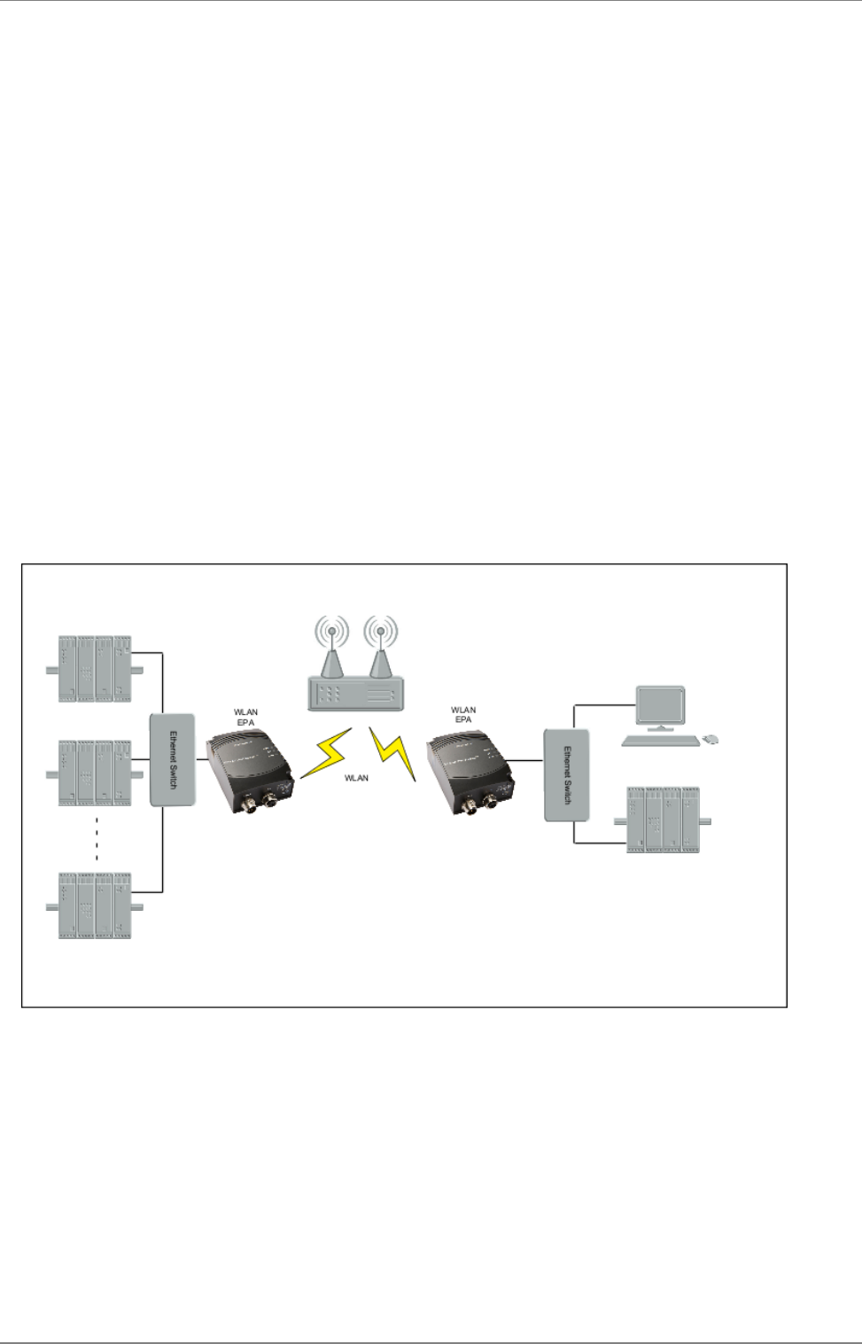
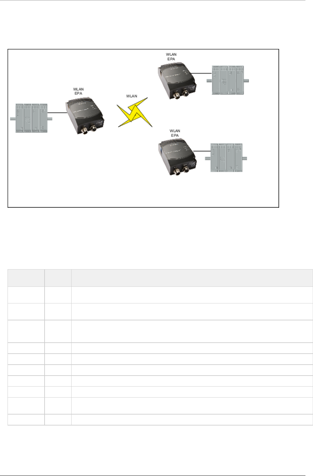
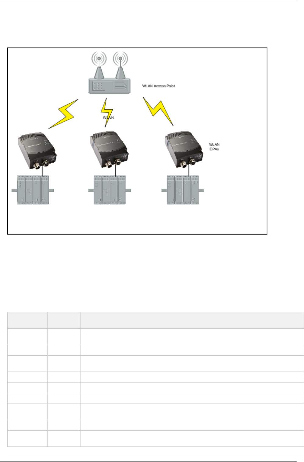
6.9 Several Ethernet devices connected in External Wireless Mode - Alternative 2
6.9.1 Overview
Three or more WEPAs connected through a WLAN Access Point. This use case requires External Wireless Mode. In this case are the
WEPAs connected to each other via a WLAN Access Point that allow us to use Managed (Infrastructure) Mode with higher performance
as a result.
6.9.2 How to setup this use case?
Both WEPAs must operate in External Wireless Mode in this use case.
Connect a PC to each of the WEPAs. See section for more information on how to connect to aUsing the WEB configuration
WEPA.
Define the WLAN connection parameters. The following parameters are required:
Parameter Required
Value
Comment
Operational
Mode
Managed
WLAN Channel Select the one used by the the Access Point.
WLAN Data
Rate
This is the maximum used data rate.
Link Adaption Yes or No
Encryption Choose the one required by the Access Point.
Autenthication Choose the one required by the Access Point.
User Name and
Key
Choose the one required by the Access Point.
SSID Choose the SSID of the Access Point.
WLAN Address Enter the MAC address of the device the WEPA is connected to or use SMART to assign the MAC
address (see next bullet).
connectBlue
Copyright © 2010 connectBlue AB Page 16 of 21
1.
1.
2.
1.
UDP Receiver Off
As an alternative to enter the MAC address manually, SMART mode 11 may be used.
NOTE! For this mode to operate it is required that the device spontaneously is sending Ethernet data on the Ethernet link.
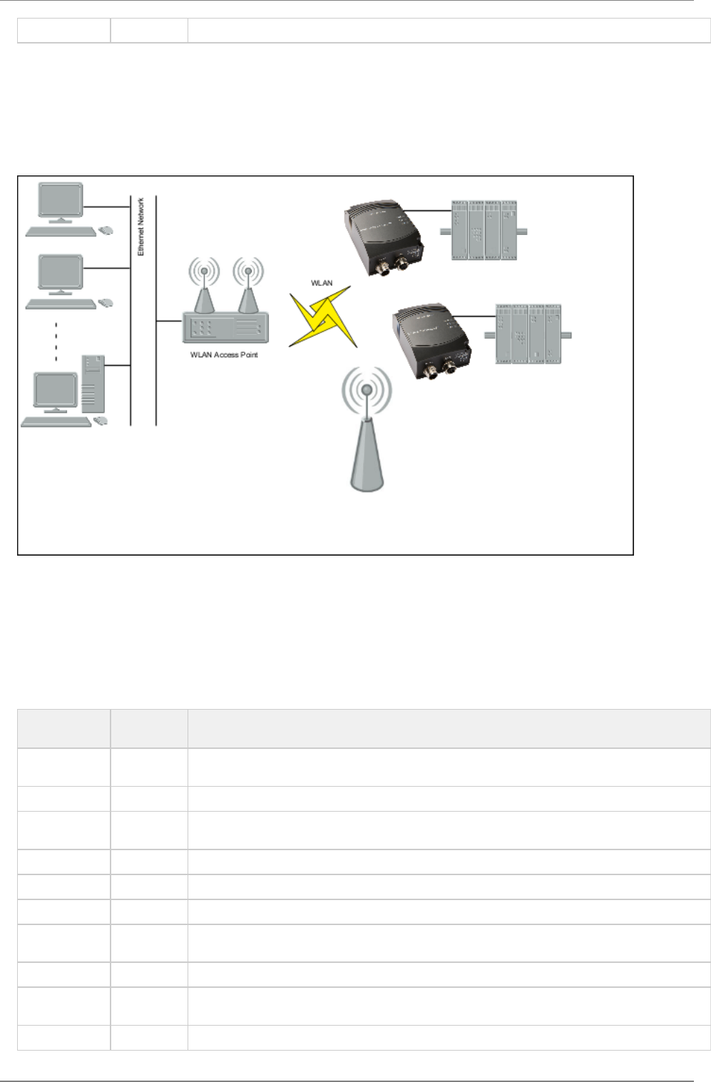
6.10 One or more WEPAs connected to a Wired Infrastructure through WLAN
6.10.1 Overview
In this use case the WEPAs are used to connect to a wired Ethernet infrastructure using a standard WLAN access point. Other WLAN
devices can of course be connected to the same access point assuming the share the same networking parameters as the WEPAs.
6.10.2 How to setup this use case?
All WEPAs must operate in External Wireless Mode in this use case.
Connect a PC to the WEPA. See section for more information on how to connect to a WEPA.Using the WEB configuration
Define the WLAN connection parameters. The following parameters are required:
Parameter Required
Value
Comment
Operational
Mode
Managed
WLAN Channel Select the one used by the the Access Point.
WLAN Data
Rate
This is the maximum used data rate.
Link Adaption Yes or No
Encryption Choose the one required by the Access Point.
Autenthication Choose the one required by the Access Point.
User Name and
Key
Choose the one required by the Access Point.
SSID Choose the SSID of the Access Point.
WLAN Address Enter the MAC address of the device the WEPA is connected to or use SMART to assign the MAC
address (see next bullet).
UDP Receiver Off
connectBlue
Copyright © 2010 connectBlue AB Page 17 of 21
1.
1.
2.
1.
As an alternative to enter the MAC address manually, SMART mode 11 may be used.
NOTE! For this mode to operate it is required that the device spontaneously is sending Ethernet data on the Ethernet link.
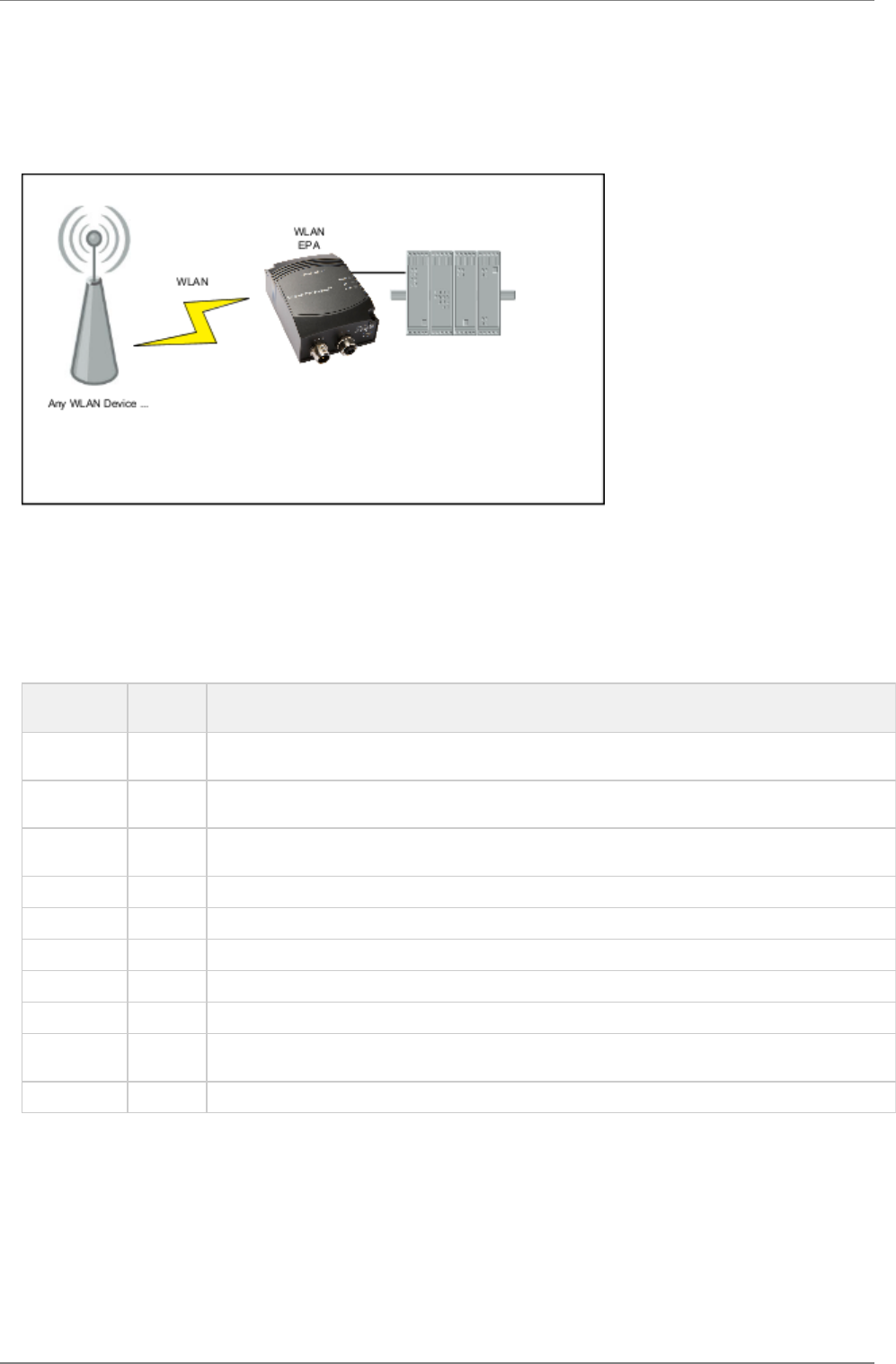
6.11 External WLAN client connected to a WEPA
6.11.1 Overview
In this use case some other WLAN client is connected to a WEPA that is connected to an Ethernet device.
6.11.2 How to setup this use case?
The WEPAs must operate in External Wireless Mode in this use case.
Connect a PC to the WEPA. See section " " for more information on how to connect to the WEPA.Using the WEB configuration
Define the WLAN connection parameters. The following parameters are required:
Parameter Required
Value
Comment
Operational
Mode
Ad-Hoc This is the only supported mode in this use case.
WLAN
Channel
Choose the same channel as the external device.
WLAN Data
Rate
This is the maximum rate used. As this always is using Ad-Hoc mode up to 11 MBit/s supported. If higher
rate is chosen it will default to a maximum of 11 MBit/s.
Link Adaption No Link adaption is not supported in Ad-Hoc mode. If yes is chosen this setting will have no effec.
Encryption WEP WEP is the only supported encryption in Ad-Hoc mode.
Autenthication Open
Key Choose the same WEP key as the external device.
SSID Choose the same SSID as the external device.
WLAN
Address
Enter the MAC address of the device the WEPA is connected to or use SMART to assign the MAC
address (see next bullet).
UDP Receiver Off
As an alternative to enter the MAC address manually, SMART mode 11 may be used.
NOTE! For this mode to operate it is required that the device spontaneously is sending Ethernet data on the Ethernet link.
The external device must be configured to support Ad-Hoc mode and with same WEP key and SSID as the WEPA.
7 Currently Unsupported Use Cases
This section shows important but currently unsupported use cases,
connectBlue
Copyright © 2010 connectBlue AB Page 18 of 21
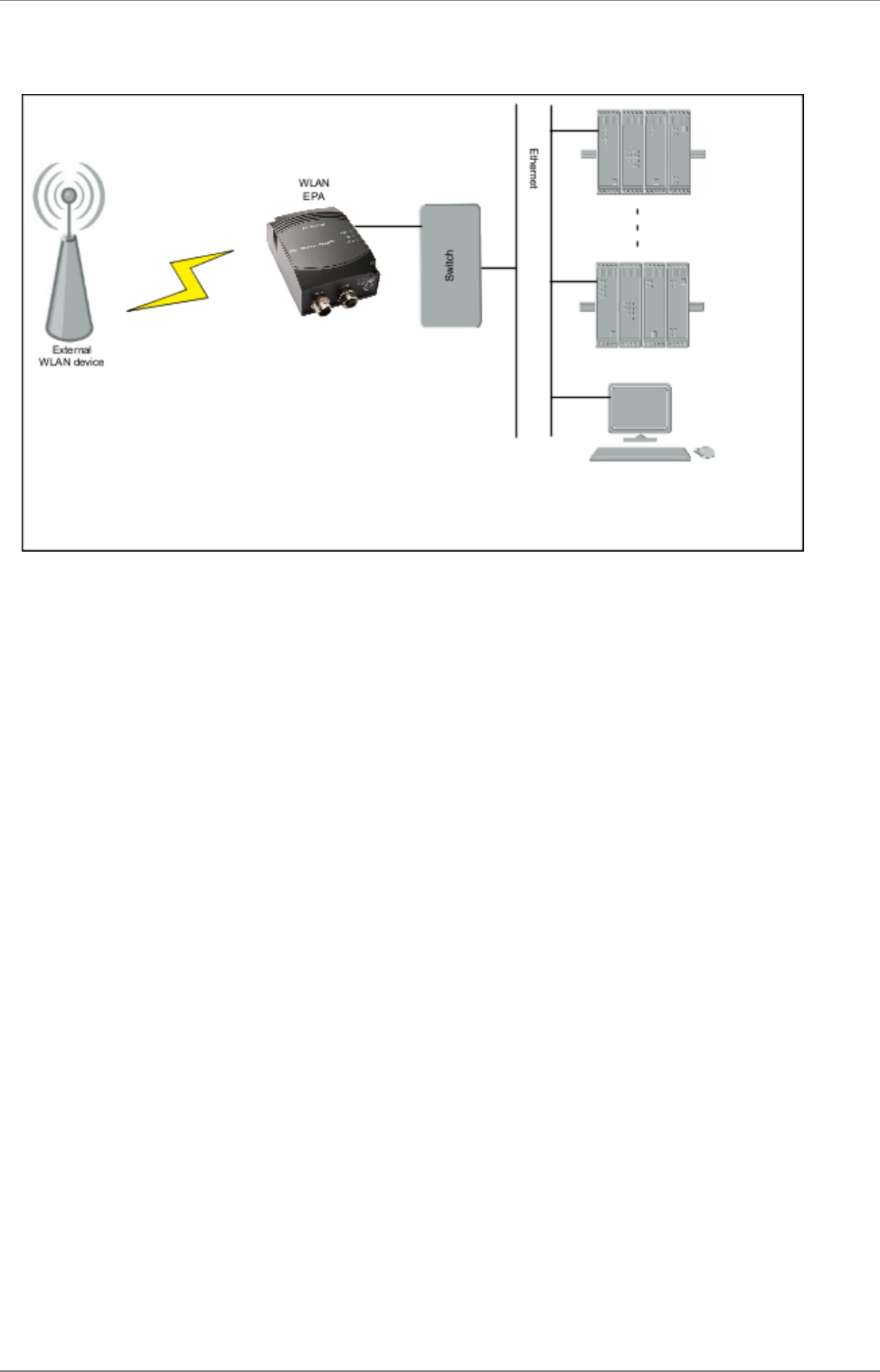
7.1 External device connected to WEPA connected to a Ethernet infrastructure

connectBlue
Copyright © 2010 connectBlue AB Page 19 of 21
1.
2.
8 Legal and Regulatory
8.1 IC and FCC compliance
IC Compliance
Operation is subject to the following two conditions:
this device may not cause harmful interference,
this device must accept any interference received, including interference that may cause undesired operation.
The installer of this radio equipment must ensure that the antenna is located or pointed such that it does not emit RF field in excess of
Health Canada limits for the general population; consult Safety Code 6, obtainable from Health Canada's website
.http://www.hc-sc.gc.ca/rpb
8.1.1 FCC statement
This device complies with Part 15 of the FCC Rules. Operation is subject to the following two conditions: (1) this device may not cause
harmful interference, and (2) this device must accept any interference received, including interference that may cause undesired
operation.
This equipment has been tested and found to comply with the limits for a Class B digital device, pursuant to Part 15 of
the FCC Rules. These limits are designed to provide reasonable protection against harmful interference in a residential
installation. This equipment generates, uses and can radiate radio frequency energy and, if not installed and used in
accordance with the instructions, may cause harmful interference to radio communications. However, there is no
guarantee that interference will not occur in a particular installation. If this equipment does cause harmful interference to
radio or television reception, which can be determined by turning the equipment off and on, the user is encouraged to
try to correct the interference by one or more of the following measures:
Reorient or relocate the receiving antenna
Increase the separation between the equipment and receiver
Connect the equipment into an outlet on a circuit different from that to which the receiver is connected
Consult the dealer or an experienced radio/TV technician for help.
8.1.1.1 Caution
Any changes or modifications NOT explicitly APPROVED by connectBlue AB could cause the module to cease to
comply with FCC rules part 15, and thus void the user's authority to operate the equipment.
Within the 5180 to 5240 MHz band (5 GHz radio channels 34 to 48) the product are restricted to indoor operations.
§15.407 statement; in case of absence of information to transmit or operational failure the product will automatically
discontinue transmission.
8.1.1.2 Ad-hoc frequencies
When operating under the definition of a client in 47 CFR §15.202 is preconfigured to use the most restrictive regulatory domain. For this
reason the available operating frequency range is limited to channel 1 - 11 (2412 - 2462 MHz) for IEEE802.11b/g. For IEEE802.11a the
available operating frequency range is limited to channels 36 - 48 (5180 - 5240 MHz).
8.1.1.3 RF-exposure statement
This modular transmitter MUST have a separation distance of at least 20 cm between the antenna and the body of the user or nearby
persons.
Any notification to the end user of installation or removal instructions about the integrated radio module is NOT allowed.

connectBlue
Copyright © 2010 connectBlue AB Page 20 of 21
8.2 Declaration of Conformity
We, , of connectBlue AB Norra Vallgatan 64 3V, SE-211 22 Malmö, Sweden
declare under our sole responsibility that our product:
cB-RWEPAgi-02
meets the essential requirements according to article of the following EC-Directive(s):
1999/5/EG Directive 1999/5/EC of the European Parliament and the council of March 1999 relating to radio and telecommunication
terminal equipment, including the mutual recognition of their conformity.
and the following harmonized standards has been applied:
ETSI EN 300 328 V1.7.1 (2006-10)
(2005)EN 61000-6-2
(2002) for the health requirements. EN 50371
15/04/2010 Malmö, Sweden
CTO of connectBlue AB
8.3 Licenses
This product contains software under the following licenses:
/*
* Copyright (c) 2001-2004 Swedish Institute of Computer Science.
* All rights reserved.
*
* Redistribution and use in source and binary forms, with or without modification,
* are permitted provided that the following conditions are met:
*
* 1. Redistributions of source code must retain the above copyright notice,
* this list of conditions and the following disclaimer.
* 2. Redistributions in binary form must reproduce the above copyright notice,
* this list of conditions and the following disclaimer in the documentation
* and/or other materials provided with the distribution.
* 3. The name of the author may not be used to endorse or promote products
* derived from this software without specific prior written permission.
*
* THIS SOFTWARE IS PROVIDED BY THE AUTHOR ``AS IS'' AND ANY EXPRESS OR IMPLIED
* WARRANTIES, INCLUDING, BUT NOT LIMITED TO, THE IMPLIED WARRANTIES OF
* MERCHANTABILITY AND FITNESS FOR A PARTICULAR PURPOSE ARE DISCLAIMED. IN NO EVENT
* SHALL THE AUTHOR BE LIABLE FOR ANY DIRECT, INDIRECT, INCIDENTAL, SPECIAL,
* EXEMPLARY, OR CONSEQUENTIAL DAMAGES (INCLUDING, BUT NOT LIMITED TO, PROCUREMENT
* OF SUBSTITUTE GOODS OR SERVICES; LOSS OF USE, DATA, OR PROFITS; OR BUSINESS
* INTERRUPTION) HOWEVER CAUSED AND ON ANY THEORY OF LIABILITY, WHETHER IN
* CONTRACT, STRICT LIABILITY, OR TORT (INCLUDING NEGLIGENCE OR OTHERWISE) ARISING
* IN ANY WAY OUT OF THE USE OF THIS SOFTWARE, EVEN IF ADVISED OF THE POSSIBILITY
* OF SUCH DAMAGE.
*
* This file is part of the lwIP TCP/IP stack.
*
* Author: Adam Dunkels <adam@sics.se>
*
*/

connectBlue
Copyright © 2010 connectBlue AB Page 21 of 21
Copyright (c) 2006-2008, Christophe Devine.
All rights reserved.
Redistribution and use in source and binary forms, with or without
modification, are permitted provided that the following conditions
are met:
* Redistributions of source code must retain the above copyright
notice, this list of conditions and the following disclaimer.
* Redistributions in binary form must reproduce the above copyright
notice, this list of conditions and the following disclaimer in the
documentation and/or other materials provided with the distribution.
* Neither the name of XySSL nor the names of its contributors may be
used to endorse or promote products derived from this software
without specific prior written permission.
THIS SOFTWARE IS PROVIDED BY THE COPYRIGHT HOLDERS AND CONTRIBUTORS
"AS IS" AND ANY EXPRESS OR IMPLIED WARRANTIES, INCLUDING, BUT NOT
LIMITED TO, THE IMPLIED WARRANTIES OF MERCHANTABILITY AND FITNESS
FOR A PARTICULAR PURPOSE ARE DISCLAIMED. IN NO EVENT SHALL THE COPYRIGHT
OWNER OR CONTRIBUTORS BE LIABLE FOR ANY DIRECT, INDIRECT, INCIDENTAL,
SPECIAL, EXEMPLARY, OR CONSEQUENTIAL DAMAGES (INCLUDING, BUT NOT LIMITED
TO, PROCUREMENT OF SUBSTITUTE GOODS OR SERVICES; LOSS OF USE, DATA, OR
PROFITS; OR BUSINESS INTERRUPTION) HOWEVER CAUSED AND ON ANY THEORY OF
LIABILITY, WHETHER IN CONTRACT, STRICT LIABILITY, OR TORT (INCLUDING
NEGLIGENCE OR OTHERWISE) ARISING IN ANY WAY OUT OF THE USE OF THIS
SOFTWARE, EVEN IF ADVISED OF THE POSSIBILITY OF SUCH DAMAGE.