u blox Malmo 1953 WLAN & Bluetooth Module User Manual
u-blox Malmo AB WLAN & Bluetooth Module
user manual

-
-Page of 1 21
Document Information
Title
Subtitle
Document type
Document number
Revision and date
Document status
u-blox reserves all rights to this document and the information contained herein. Products, names, logos and designs described
herein may in whole or in part be subject to intellectual property rights. Reproduction, use, modification or disclosure to third
parties of this document or any part thereof without the express permission of u-blox is strictly prohibited.
The information contained herein is provided “as is” and u-blox assumes no liability for the use of the information. No
warranty, either express or implied, is given, including but not limited, with respect to the accuracy, correctness, reliability and
fitness for a particular purpose of the information. This document may be revised by u-blox at any time. For most recent
documents, visit . Copyright © 2014, u-blox AG.www.u-blox.com
u-blox® is a registered trademark of u-blox Holding AG in the EU and other countries. ARM® is the registered trademark of
ARM Limited in the EU and other countries.

-
-Page of 2 21
Contents
1 Introduction . . . . . . . . . . . . . . . . . . . . . . . . . . . . . . . . . . . . . . . . . . . . . . . . . . . . . 4
1.1 Document Overview . . . . . . . . . . . . . . . . . . . . . . . . . . . . . . . . . . . . . . . . . . . . . . . . . . . . . . . . . . 4
1.2 Key Features . . . . . . . . . . . . . . . . . . . . . . . . . . . . . . . . . . . . . . . . . . . . . . . . . . . . . . . . . . . . . . . . . 4
1.3 Product Variants . . . . . . . . . . . . . . . . . . . . . . . . . . . . . . . . . . . . . . . . . . . . . . . . . . . . . . . . . . . . . 5
2 Electrical Interface and Connectors . . . . . . . . . . . . . . . . . . . . . . . . . . . . . . . . . . . 6
2.1 Primary Side Connector . . . . . . . . . . . . . . . . . . . . . . . . . . . . . . . . . . . . . . . . . . . . . . . . . . . . . . . . 6
2.2 Secondary Side Connector . . . . . . . . . . . . . . . . . . . . . . . . . . . . . . . . . . . . . . . . . . . . . . . . . . . . . . 7
2.3 J4-20 RF-port solder land . . . . . . . . . . . . . . . . . . . . . . . . . . . . . . . . . . . . . . . . . . . . . . . . . . . . . . . 7
2.4 Electrical Characteristics . . . . . . . . . . . . . . . . . . . . . . . . . . . . . . . . . . . . . . . . . . . . . . . . . . . . . . . 7
2.4.1 Power Supply . . . . . . . . . . . . . . . . . . . . . . . . . . . . . . . . . . . . . . . . . . . . . . . . . . . . . . . . . . . . . . 7
2.4.2 I/O DC Characteristics . . . . . . . . . . . . . . . . . . . . . . . . . . . . . . . . . . . . . . . . . . . . . . . . . . . . . . . . 8
2.4.3 LPO Requirements . . . . . . . . . . . . . . . . . . . . . . . . . . . . . . . . . . . . . . . . . . . . . . . . . . . . . . . . . . 8
2.5 Host Interface . . . . . . . . . . . . . . . . . . . . . . . . . . . . . . . . . . . . . . . . . . . . . . . . . . . . . . . . . . . . . . . . 8
2.5.1 Wireless LAN and SDIO . . . . . . . . . . . . . . . . . . . . . . . . . . . . . . . . . . . . . . . . . . . . . . . . . . . . . . . 8
2.5.2 Bluetooth UART . . . . . . . . . . . . . . . . . . . . . . . . . . . . . . . . . . . . . . . . . . . . . . . . . . . . . . . . . . . . 8
2.6 Environmental Characteristics . . . . . . . . . . . . . . . . . . . . . . . . . . . . . . . . . . . . . . . . . . . . . . . . . . . 9
2.7 Mechanical Characteristics . . . . . . . . . . . . . . . . . . . . . . . . . . . . . . . . . . . . . . . . . . . . . . . . . . . . . 9
3 Antenna Information . . . . . . . . . . . . . . . . . . . . . . . . . . . . . . . . . . . . . . . . . . . . . . 9
3.1 Caution . . . . . . . . . . . . . . . . . . . . . . . . . . . . . . . . . . . . . . . . . . . . . . . . . . . . . . . . . . . . . . . . . . . . . 9
3.2 External Antennas . . . . . . . . . . . . . . . . . . . . . . . . . . . . . . . . . . . . . . . . . . . . . . . . . . . . . . . . . . . 10
3.2.1 Antennas . . . . . . . . . . . . . . . . . . . . . . . . . . . . . . . . . . . . . . . . . . . . . . . . . . . . . . . . . . . . . . . . . 10
4 Mounting Information . . . . . . . . . . . . . . . . . . . . . . . . . . . . . . . . . . . . . . . . . . . . 11
4.1 Module Dimensions . . . . . . . . . . . . . . . . . . . . . . . . . . . . . . . . . . . . . . . . . . . . . . . . . . . . . . . . . . 11
4.2 PCB Solder Lands . . . . . . . . . . . . . . . . . . . . . . . . . . . . . . . . . . . . . . . . . . . . . . . . . . . . . . . . . . . . 12
4.2.1 Host Board . . . . . . . . . . . . . . . . . . . . . . . . . . . . . . . . . . . . . . . . . . . . . . . . . . . . . . . . . . . . . . . . 12
4.2.2 Mounting Process . . . . . . . . . . . . . . . . . . . . . . . . . . . . . . . . . . . . . . . . . . . . . . . . . . . . . . . . . . 13
5 Regulatory Information . . . . . . . . . . . . . . . . . . . . . . . . . . . . . . . . . . . . . . . . . . . 13
5.1 CE compliance . . . . . . . . . . . . . . . . . . . . . . . . . . . . . . . . . . . . . . . . . . . . . . . . . . . . . . . . . . . . . . 13
5.1.1 Equipment classes . . . . . . . . . . . . . . . . . . . . . . . . . . . . . . . . . . . . . . . . . . . . . . . . . . . . . . . . . . 13
5.1.2 Declaration of Conformity . . . . . . . . . . . . . . . . . . . . . . . . . . . . . . . . . . . . . . . . . . . . . . . . . . . 14
5.2 IC and FCC compliance . . . . . . . . . . . . . . . . . . . . . . . . . . . . . . . . . . . . . . . . . . . . . . . . . . . . . . . 15
5.2.1 IC compliance . . . . . . . . . . . . . . . . . . . . . . . . . . . . . . . . . . . . . . . . . . . . . . . . . . . . . . . . . . . . . 15
5.2.2 Conformité aux normes d’IC . . . . . . . . . . . . . . . . . . . . . . . . . . . . . . . . . . . . . . . . . . . . . . . . . 15
5.2.3 FCC statement . . . . . . . . . . . . . . . . . . . . . . . . . . . . . . . . . . . . . . . . . . . . . . . . . . . . . . . . . . . . . 16
5.3 Compliance with RoHS Directive . . . . . . . . . . . . . . . . . . . . . . . . . . . . . . . . . . . . . . . . . . . . . . . 19

-
-Page of 3 21
6 Guidelines for Efficient and Safe Use . . . . . . . . . . . . . . . . . . . . . . . . . . . . . . . . 19
6.1 General . . . . . . . . . . . . . . . . . . . . . . . . . . . . . . . . . . . . . . . . . . . . . . . . . . . . . . . . . . . . . . . . . . . . 19
6.2 Product Care . . . . . . . . . . . . . . . . . . . . . . . . . . . . . . . . . . . . . . . . . . . . . . . . . . . . . . . . . . . . . . . . 19
6.3 Radio Frequency Exposure . . . . . . . . . . . . . . . . . . . . . . . . . . . . . . . . . . . . . . . . . . . . . . . . . . . . 19
6.4 Electronic Equipment . . . . . . . . . . . . . . . . . . . . . . . . . . . . . . . . . . . . . . . . . . . . . . . . . . . . . . . . 20
6.5 Potentially Explosive Atmospheres . . . . . . . . . . . . . . . . . . . . . . . . . . . . . . . . . . . . . . . . . . . . . . 20
6.6 Safety Compliance . . . . . . . . . . . . . . . . . . . . . . . . . . . . . . . . . . . . . . . . . . . . . . . . . . . . . . . . . . . 20
-
-Page of 4 21
1 Introduction
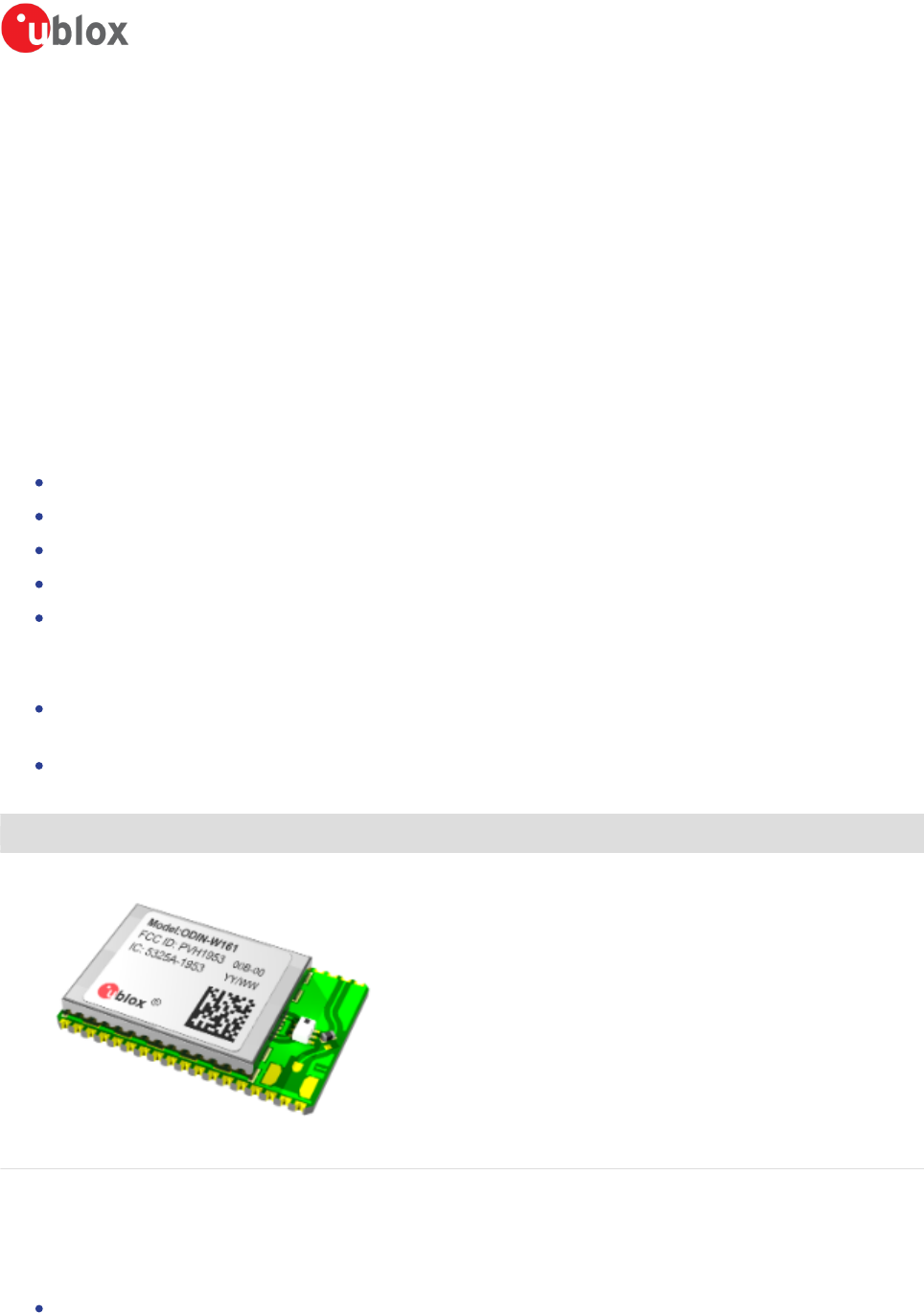
The ODIN-W161 is a Multi Radio Module providing both IEEE 802.11a,b,g,n Wireless LAN and
Bluetooth 4.0, including Classic Bluetooth and Bluetooth low energy. It has been developed for
integration in industrial devices. The module provides features such as low power, robustness,
reliability and compatibility. By using the module the work needed to implement IEEE 802.11 and/or
Bluetooth in a device is minimized as it provides, together with the driver package, all software,
hardware, type approval, EMC certification etc. It is developed for reliable, high demanding industrial
devices and applications and delivers high performance.
The Wireless LAN section of the module can be operated on 5 frequency bands and conforms to IEEE
802.11a,b,g and 802.11n single stream.
ISM Band (2412 – 2462 MHz), 11 channels with a separation of 5MHz
UNII band-1 (5180 – 5240 MHz), 4 channels with a separation of 20MHz
UNII band-2 (5260 – 5320 MHz), 4 channels with a separation of 20MHz
UNII band-2e (5500 – 5700 MHz), 8 channels with a separation of 20MHz
UNII band-3 (5745 – 5825 MHz), 5 channels with a separation of 20MHz
The Bluetooth section of ODIN-W160 operates in the unlicensed ISM band between 2402 – 2480 MHz
and has two operating modes with somewhat different behaviour.
Bluetooth Classic (BT+EDR)
In this operating mode it uses 79 RF channels with 1 MHz spacing
Bluetooth Low Energy (BLE)
In this operating mode it uses 39 RF channels with 2 MHz spacing
ODIN-W161
1.1 Document Overview
This User Manual is applicable to the following Wireless LAN module:
ODIN-W161
1.2 Key Features

-
-Page of 5 21
1.2 Key Features
Multiradio module:
Dual-band Wireless LAN operation (IEEE 802.11-2007a,b,g and single stream IEEE 802.11
n)
Bluetooth 4.0
Ready-to-use:
No production tests required
RF tuned from factory
Contains own MAC address
Host interfaces:
Wireless LAN: SDIO
Bluetooth: UART
RF parameters and MAC address: I C
2
Small footprint
22.3 x 14.8 x 2.9 mm
WEP, AES hardware accelerators
WPA and WPA2 support - both personal and enterprise modes
Quality of Service: 802.11e and WMM
Ad-hoc and infrastructure mode
Radio type approved for Europe
Unlicensed Modular Transmitter Approval for US (FCC) and Canada (IC)
Compliant with EMC standards
Medical approval
Industrial temperature range -40 to +85 °C
Support for low power modes
RF-port via solder land
1.3 Product Variants
Product name Regulatory ID
FCC ID
IC ID
Description
ODIN-W161 Model: ODIN-W161
PVH1953
5325A-1953
Multi Radio Module with solder land RF-port
-
-Page of 6 21
2 Electrical Interface and Connectors
Host interface and control signals are accessible via PCB solder lands at the edge of the PCB.
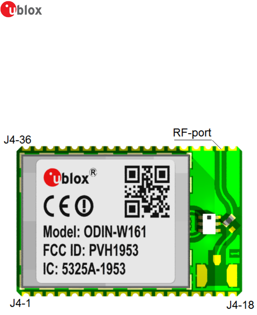
2.1 Primary Side Connector
Top view of module, J4 is the 2 x 18 pin solder lands.
-
-Page of 7 21
2.2 Secondary Side Connector
2.3 J4-20 RF-port solder land
The RF-port of the module is accessed via solder land J4-20, it is for both transmit and receive. The
port impedance to match is 50 ohm.
J4 pin nr Pin name Signal level Type Description
20 Ant-1 RF I/O U.FL. external antenna port (50 ohm)
2.4 Electrical Characteristics
2.4.1 Power Supply
Read the safety notes in section Guidelines for Efficient and Safe Use before using the
modules.
Supply Voltage Requirements
Symbol Parameter Min Typ. Max Unit
VDD Supply voltage 3.0 3.3 3.6 V
VIO IO Supply voltage 1.75 1.8 1.9 V
-
-Page of 8 21
2.4.2 I/O DC Characteristics
Symbol Parameter Min Typ Max Unit
VIL LOW level input voltage 0 0.35 x VIO V
VIH HIGH level input voltage 0.65 x VIO VIO V
VOL LOW level output voltage 0.0 0.45 V
VOH HIGH level output voltage V - 0.45
IO VIO V
IIO Sink and source current 8.0 mA
CIO Input capacitance 8 pF
2.4.3 LPO Requirements
Symbol Parameter Min Typ Max Unit
LPO-32kHz Frequency 32763 32768 32773 Hz
2.5 Host Interface
The module has two primary host interfaces, SDIO for the Wireless LAN section and UART for the
Bluetooth section.
2.5.1 Wireless LAN and SDIO
The interface between the host and the module is a standard SDIO interface (See SDIO spec Version
2.0) with Out Of Band interrupt, supporting maximum clock rate of 25MHz. The SDIO interface also
supports the following features:
Both 1 and 4 bit data bus
Functions number 0 and 2
Multi-Block data transfer
The WLAN block uses function 2. Function 0 is used for the common I/O area.
2.5.2 Bluetooth UART
The module incorporates one UART dedicated to the Bluetooth Host Controller Interface (HCI)
transport layer. The HCI interface is used to transport commands, events, ACL and synchronous data
between the device and its host using HCI data packets.
The following HCI transport layers are supported (detected automatically when communication
starts):
HCI four-wire (H4)
HCI three-wire (H5)
-
-Page of 9 21
The HCI interface has a 256 byte receive buffer and supports most baud rates, including all normal PC
rates, up to a maximum of 4 Mbps. After power-up, the baud rate is set for 115.2kbps. The maximum
baud rate deviation supported is -2.5%, +1.5%.
The baud rate can be changed with a vendor specific command. The module responds with a
Command Complete Event (still at 115.2kbps), after which the baud rate change takes place. The only
parameter needed is the desired baud rate.
HCI hardware includes the following features:
Receiver detection of break, idle, framing, FIFO overflow, and parity error conditions
Transmitter underflow detection
CTR/RTS hardware flow control (H4)
XON/XOFF soft flow control (H5)
Parameter Values
Baud rates Min: 37.5 kbps
Max: 4000 kbps
Default baud rate 115.2 kbps
Data bits 8
Stop bits 1
Parity none
Flow control None, XON/XOFF, CTS/RTS
2.6 Environmental Characteristics
Parameter Min Typ Max Unit
Storage temperature -40 +95 degC
Operating temperature -40 +85 degC
2.7 Mechanical Characteristics
Parameter Value type Value Unit
Weight Typ 1.5 g
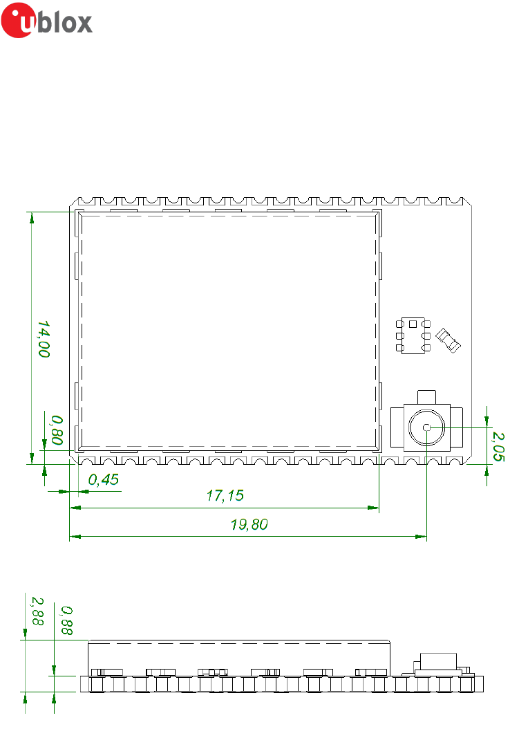
Outline dimension Typ 22.3 x 14.8 x 2.9 (+/- 0.1 mm) mm
3 Antenna Information
This chapter gives an overview of the different external antennas that can be fitted to the module.
3.1 Caution

-
-Page of 10 21
This radio transmitter IC: 5325A-1953 has been approved by Industry Canada to operate with
the antenna types listed below with the maximum permissible gain and required antenna
impedance for each antenna type indicated. Antenna types not included in this list, having a
gain greater than the maximum gain indicated for that type, are strictly prohibited for use
with this device.
Cet émetteur radio IC: 5325A-1953 a été approuvé par Industry Canada pour fonctionner
avec les types d’antenne énumérés ci-dessous avec le gain maximum autorisé et l’impédance
nécessaire pour chaque type d’antenne indiqué. Les types d’antenne ne figurant pas dans
cette liste et ayant un gain supérieur au gain maximum indiqué pour ce type-là sont
strictement interdits d’utilisation avec cet appareil.
3.2 External Antennas
External antennas are connected to the module via the solder land RF-port (J4 pin-20). The section
below shows the antenna reference design as
one type example of how to connect the antenna to the solder land RF-port via a 50-ohm stripline
and an impedance matching network.
3.2.1 Antennas
Part Number -
Name ODIN-W161 Antenna Reference design UBX15010679
Manufacture Fractus SMD antenna, FR05-S1-NO-1-003
Polarization Linear
Gain / Imp. +3.0 dBi / 50ohm @ 2.4 GHz
+3.0 dBi / 50ohm @ 5 GHz
Size 27 x 36 mm
Comment The reference design must be in strict accordance with
ODIN-W161 Antenna reference design UBX15010679
Approval FCC, IC, R&TTE
-
-Page of 11 21
4 Mounting Information
4.1 Module Dimensions
-
-Page of 12 21
1.
Tolerances:
Outline dimensions +/- 0.2mm
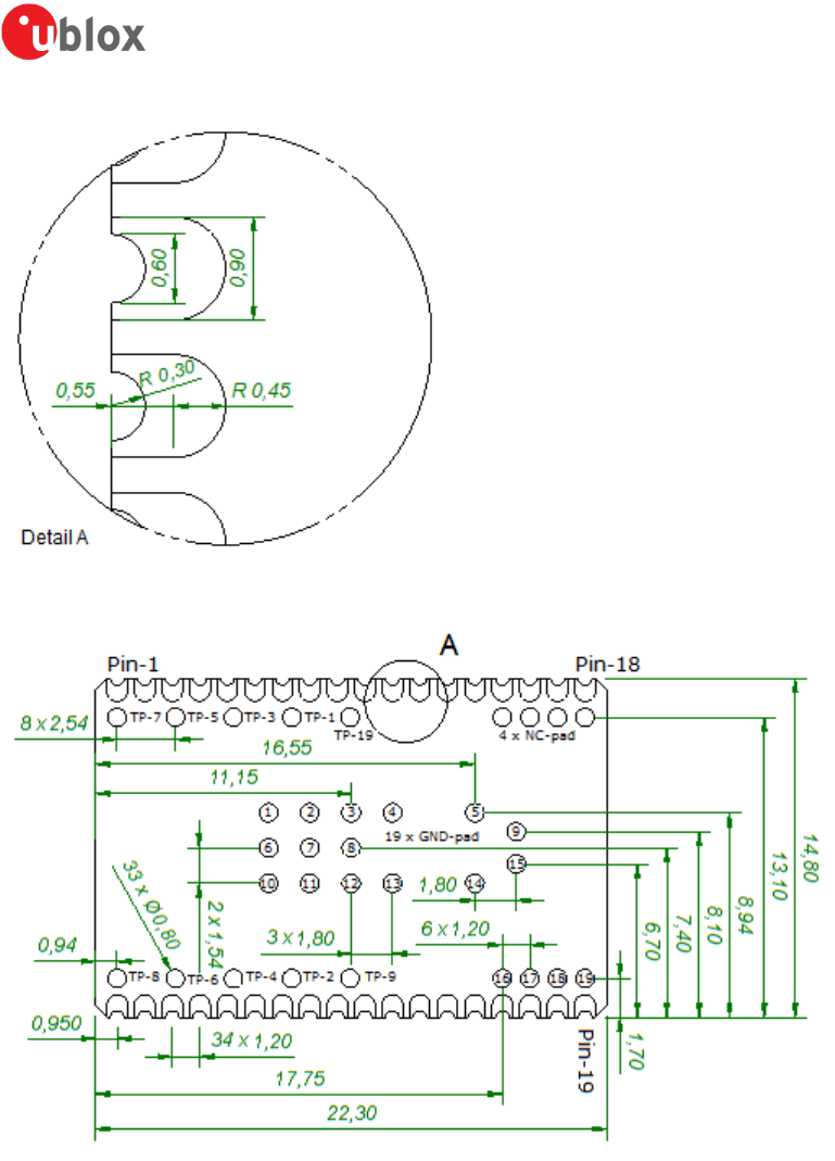
4.2 PCB Solder Lands
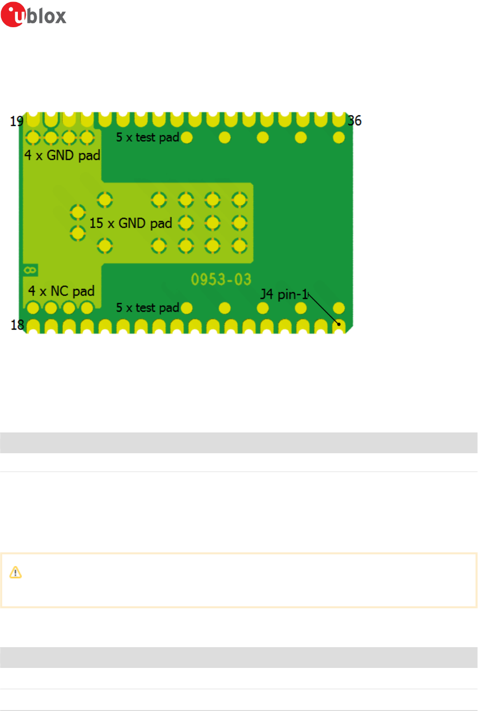
4.2.1 Host Board
The host PCB footprint should not contain any traces or vias under the module except the pads
connecting to the solder lands of connector J4- and the 19 supplementary GND-pads.
TP- and NC-pads are not mandatory but can be used to get a better balance of the solder process.

-
-Page of 13 21
4.2.2 Mounting Process
Although u-blox devices will withstand two re-flow soldering processes (T < 250°C) we strongly
max
recommend the modules not being subjected to more than one soldering process after being shipped
from u-blox thus the modules are populated on the host product in the final solder processing step.
The PCB in our modules is UL recognized ZPMV2 min. 130 °C flame class V-0 with ENIG coated
solder lands.
The modules are produced in a lead-free process with a lead-free soldering paste.
It is recommended that the customers make their own electrical, climate, stress and vibration
tests on the final assembled product to secure that the manufacturing process hasn't damaged
or affected the module in any way.
The modules are delivered in ESD bags (for small quantities) or tape-on-reel
Modules delivered on tape-on-reel are packaged in sealed drypack" bags, MSL-3
Modules delivered in ESD bag are not in a sealed drypack
The device recommended maximum re-flow temperature is 245°C for 10 sec.
The device absolute maximum re-flow temperature is 250°C for 3 sec.
5 Regulatory Information
5.1 CE compliance
5.1.1 Equipment classes
Depending on which frequency bands this multi-radio module can operate in it is defined as either
class-1 or class-2 radio equipment.
The End-product that utilise the module inherits the equipment class of the module.
Class-1 radio equipment can be placed on the market and put into service without restrictions.
(article 1 of Commission Decision 2000/299/EC of April 6 2000)
Class-2 radio equipment is equipment for which Member States apply restrictions as indicated in
Article 1(2) of the Decision, which also assigns the “Alert Sign” as “Equipment Class Identifier”
for this class.
This multi-radio module is defined as class-1 radio equipment when it is restricted to operate in the
following frequency bands:
Bluetooth ISM band 2400 – 2483.5 MHzclassic,
Bluetooth , ISM band 2400 – 2483.5 MHzLow Energy
WLAN, ISM band 2400 – 2483.5 MHz
WLAN, U-NII band-2e 5470 – 5725 MHz
If the end product allows the multi radio module to be operated in the band 5150 – 5350 MHz (WLAN
channel: 36 – 64) it is defined as class-2 radio equipment and must be marked accordingly.
Class-2 radio equipment must have the "alert" sign affixed on the equipment, packaging and printed
in the user instruction manual.
-
-Page of 14 21
Guidance on how the End product that utilise this module is marked in accordance with the
R&TTE directive is found in the following links:
http://ec.europa.eu/enterprise/sectors/rtte/documents/index_en.htm#h2-5
http://ec.europa.eu/enterprise/sectors/rtte/documents/guidance/index_en.htm
A direct link to the quick guide to the marking requirements can be found here:
http://ec.europa.eu/enterprise/sectors/rtte/files/guidance/guidance_en.pdf
The ODIN-W161 uses harmonised frequency bands thus it is comprised by subclass H01 of class 2
equipment, for which notification in accordance with article 6(4) of the R&TTE directive is not
necessary.
A definition of subclasses of Class 2 equipment can be found in the following link:
http://ec.europa.eu/enterprise/sectors/rtte/files/rtte-subclass2_en.pdf
The table below shows the restrictions when operating the module in WLAN mode within the
European countries
band Channel number Channel frequency Indoor Use allowed Outdoor Use allowed Radio Equipment Class
ISM 1 - 11 2412 - 2462 MHz Yes Yes 1
U-NII 1 36 - 48 5180 - 5240 MHz Yes No 2
U-NII 2 52 - 64 5260 - 5320 MHz Yes No 2
U-NII 2e 100 - 140 5500 - 5700 MHz Yes Yes 1
U-NII 3 149 - 165 5745 - 5825 MHz No No -
5.1.2 Declaration of Conformity
We, u-blox Malmö AB, of
Östra Varvsgatan 4, 5tr
SE-211 75 Malmö, Sweden
declare under our sole responsibility that our product:
ODIN-W161
to which this declaration relates, conforms to the following product specifications:
R&TTE Directive 1999/5/EC
Effective use of frequency spectrum:
EN 300 328 V1.8.1 (2012-06)
EN 301 893 V1.7.1 (2012-06)

-
-Page of 15 21
1.
2.
1.
2.
EMC:
EN 301 489-1 V1.9.2 (2011-09)
EN 301 489-17 V2.2.1 (2012-09)
EN 61000-6-2 (2005)
Health and safety:
EN 60950-1:2006 + A11:2009
IEC 60950-1:2005
EN 62311:2008 (WLAN)
EN 62479:2010 (BT + BLE)
Medical Electrical Equipment
IEC 60601-1-2 : 2007
5.2 IC and FCC compliance
5.2.1 IC compliance
This device complies with Industry Canada licence-exempt RSS standard(s).
Operation is subject to the following two conditions:
this device may not cause interference, and
this device must accept any interference, including interference that may cause undesired
operation of the device.
Under Industry Canada regulations, this radio transmitter may only operate using an antenna of a
type and maximum (or lesser) gain approved for the transmitter by Industry Canada. To reduce
potential radio interference to other users, the antenna type and its gain should be so chosen that the
equivalent isotropically radiated power (e.i.r.p.) is not more than that necessary for successful
communication.
The device for operation in the band 5150-5250 MHz is only for indoor use to reduce the potential for
harmful interference to co-channel mobile satellite systems; the maximum antenna gain permitted for
devices in the bands 5250-5350 MHz and 5470-5725 MHz shall comply with the e.i.r.p. limit; and the
maximum antenna gain permitted for devices in the band 5725-5825 MHz shall comply with the e.i.r.
p. limits specified for point-to-point and non point-to-point operation as appropriate.
Operation in the 5600-5650 MHz band is not allowed in Canada. High-power radars are allocated as
primary users (i.e. priority users) of the bands 5250-5350 MHz and 5650-5850 MHz and that these
radars could cause interference and/or damage to LE-LAN devices.
This equipment complies with IC RSS-102 radiation exposure limits set forth for an uncontrolled
environment. This equipment should be installed and operated with minimum distance 20 cm
between the radiator & your body.
5.2.2 Conformité aux normes d’IC
Cet appareil est conforme à la(aux) norme(s) RSS sans licence d’Industry Canada.
Son utilisation est soumise aux deux conditions suivantes :
Cet appareil ne doit pas causer d’interférences et
il doit accepter toutes interférences reçues, y compris celles susceptibles d’avoir des effets
indésirables sur son fonctionnement.

-
-Page of 16 21
1.
2.
Conformément aux réglementations d’Industry Canada, cet émetteur radio ne peut fonctionner qu’à l’
aide d’une antenne dont le type et le gain maximal (ou minimal) ont été approuvés pour cet émetteur
par Industry Canada. Pour réduire le risque d’interférences avec d’autres utilisateurs, il faut choisir le
type d’antenne et son gain de telle sorte que la puissance isotrope rayonnée équivalente (p.i.r.e) ne
soit pas supérieure à celle requise pour obtenir une communication satisfaisante.
Le dispositif de fonctionnement dans la bande 5150-5250 MHz est réservé à une utilisation en
intérieur pour réduire le risque d'interférences nuisibles à la co-canal systèmes mobiles par satellite, le
gain d'antenne maximal autorisé pour les appareils dans les bandes 5250-5350 MHz et 5470-5725 MHz
doit se conformer à la pire limite, et le gain d'antenne maximal autorisé pour les appareils dans la
bande 5725-5825 MHz doivent être conformes avec le pire limites spécifiées à point-à-ponctuelles et
non point-à-point de fonctionnement selon qu'il convient.
Opération dans la bande 5600-5650 MHz n'est pas autorisée au Canada. Haute puissance radars sont
désignés comme utilisateurs principaux (c.-àutilisateurs prioritaires) des bandes 5250-5350 MHz et
5650-5850 MHz et que ces radars pourraient causer des interférences et / ou des dommages à
dispositifs LAN-EL.
Cet équipement respecte les limites d’exposition aux rayonnements IC RSS-102 définies pour un
environnement non contrôlé. Il doit être installé et utilisé en maintenant une distance minimum de 20
cm entre le radiateur et votre corps.
5.2.3 FCC statement
This device complies with Part 15 of the FCC Rules. Operation is subject to the following two
conditions:
this device may not cause harmful interference, and
this device must accept any interference received, including interference that may cause
undesired operation.
This equipment has been tested and found to comply with the limits for a Class B digital device, pursuant to Part 15 of the
FCC Rules. These limits are designed to provide reasonable protection against harmful interference in a residential
installation. This equipment generates, uses and can radiate radio frequency energy and, if not installed and used in
accordance with the instructions, may cause harmful interference to radio communications. However, there is no guarantee
that interference will not occur in a particular installation. If this equipment does cause harmful interference to radio or
television reception, which can be determined by turning the equipment off and on, the user is encouraged to try to correct
the interference by one or more of the following measures:
Reorient or relocate the receiving antenna
Increase the separation between the equipment and receiver
Connect the equipment into an outlet on a circuit different from that to which the receiver is
connected
Consult the dealer or an experienced radio/TV technician for help.
End product labelling requirements
For an end product using the product ODIN-W161 there MUST be a label containing, at least, the
following information:
This device contains
FCC ID: PVH1953
IC: 5325A-1953

-
-Page of 17 21
1.
2.
1.
2.
1.
2.
The label must be affixed on an exterior surface of the end product such that it will be visible upon
inspection in compliance with the modular approval guidelines developed by the FCC.
FCC end product labelling
In accordance with 47 CFR § 15.19 the end product shall bear the following statement in a
conspicuous location on the device:
"This device complies with Part 15 of the FCC Rules. Operation is subject to the following two
conditions:
this device may not cause harmful interference, and
this device must accept any interference received, including interference that may cause
undesired operation."
When the device is so small or for such use that it is not practicable to place the statement
above on it, the information shall be placed in a prominent location in the instruction manual or
pamphlet supplied to the user or, alternatively, shall be placed on the container in which the device is
marketed. However, the FCC ID label must be displayed on the device.
In case, where the final product will be installed in locations where the end-consumer
is not able to see the FCC ID and/or this statement, the FCC ID and the statement shall also be included
in the end-product manual.
IC end product labelling
User manuals for licence-exempt LPDs shall contain the following or equivalent statements in a
conspicuous position:
Operation is subject to the following two conditions:
this device may not cause interference, and
this device must accept any interference, including interference that may cause undesired
operation of the device.
Étiquetage du produit final conforme à IC
Les manuels d’utilisation d’appareils de faible puissance, sans licence, feront figurer à un endroit bien
visible les mentions suivantes ou équivalentes:
Son utilisation est soumise aux deux conditions suivantes:
Cet appareil ne doit pas causer d’interférences et
il doit accepter toutes interférences reçues, y compris celles susceptibles d’avoir des effets
indésirables sur son fonctionnement.
Antenna
Our module ODIN-W161 is for OEM integrations only.
The module must in the end-product be installed in such manner that only the authorized antennas
can be used.
Caution

-
-Page of 18 21
Caution
Any changes or modifications NOT explicitly APPROVED by u-blox Malmö AB could cause the
module to cease to comply with FCC rules part 15, and thus void the user's authority to
operate the equipment.
Within the frequency band 5150 to 5250 MHz the module type ODIN-W161 is restricted to
indoor operations to reduce any potential for harmful interference to co-channel MSS
operation.
§15.407 statement; in case of absence of information to transmit or operational failure the
module types ODIN-W161 will automatically discontinue transmission.
Ad-hoc frequencies
When operating at the frequencies of U-NII band-2 (5260 -5320 MHz), U-NII band-2e (5500 – 5700
MHz) and U-NII band-3 (5745 – 5825 MHz)
the module is configured to function under the definition of a client in 47 CFR §15.202.
As a DFS client without radar detection using passive scan ODIN-W161 is not able to select channel or
initiate a network.
Active scan and ability to initiate network (Ad-hoc) is only supported for operation on channels 1 - 11
(2412 - 2462 MHz) and channels 36 - 48 (5180 - 5240 MHz).
RF-exposure statement
This equipment complies with FCC radiation exposure limits set forth for an uncontrolled
environment. This equipment should be installed and operated with minimum distance 20 cm
between the radiator & your body.
This equipment complies with IC RSS-102 radiation exposure limits set forth for an uncontrolled
environment. This equipment should be installed and operated with minimum distance 20 cm
between the radiator & your body.
Cet équipement est conforme aux limites d'exposition de rayonnement d'IC RSS-102 déterminées pour
un environnement non contrôlé. Cet équipement devrait être installé et actionné avec la distance
minimum 20 cm entre le radiateur et votre corps.
Any notification to the end user of installation or removal instructions about the integrated radio
module is NOT allowed

-
-Page of 19 21
5.3 Compliance with RoHS Directive
The ODIN-W161 are produced according to the RoHS (Restriction of the use of certain Hazardous
Substances in electrical and electronic equipment) directive and complies with the directive.
6 Guidelines for Efficient and Safe Use
6.1 General
Read this information before using your ODIN-W161 module.
For any exceptions, due to national requirements or limitations, when using your WLAN module,
please contact u-blox Malmö AB.
6.2 Product Care
Do not expose your product to liquid or moisture.
Do not expose you product to extreme hot or cold temperature.
Do not expose your product to lit candles, cigarettes, cigars, open flames, etc.
Do not drop, throw or try to bend your product since rough treatment could damage your
product.
Do not attempt to disassemble your product. Doing so will void warranty. The product does not
contain consumer serviceable or replaceable components. Service should only be performed by
connectBlue AB.
Do not paint your product as the paint could prevent normal use.
If your product is not to be used for a longer period, store it in a dry place free from damp, dust
and not subjected to extreme temperatures.
The clearance and creepage distances required by the end product must be withheld when the
module is installed.
The cooling of the end product shall not negatively be influenced by the installation of the
module when the module is installed.
6.3 Radio Frequency Exposure
The ODIN-W161 WLAN module contains a small radio transmitter and receiver.
During communication with other WLAN products the ODIN-W161 module transmits and receives
radio frequency (RF) electromagnetic fields (microwaves) in the frequency range 2412 - 2462 MHz,
5180 - 5240 MHz, 5260 - 5320 MHz, and 5500 - 5700 MHz.

-
-Page of 20 21
The output power of the radio transmitter is very low.
When using the module, you will be exposed to some of the transmitted RF energy. This exposure is
well below the prescribed limits in all national and international RF safety standards and regulations.
6.4 Electronic Equipment
Most modern electronic equipment, for example, in hospitals and cars, is shielded from RF energy.
However, certain electronic equipment is not. Therefore:
This equipment emits RF energy. Please insure that all medical devices used in proximity to
this device meet appropriate susceptibility specifications for this type of RF energy.
6.5 Potentially Explosive Atmospheres
Turn off your electronic device before entering an area with potentially explosive atmosphere. It is
rare, but your electronic device could generate sparks. Sparks in such areas could cause an explosion
or fire resulting in bodily injury or even death.
Areas with a potentially explosive atmosphere are often, but not always, clearly marked. They include
fueling areas, such as petrol station, below deck on boats, fuel or chemical transfer or storage
facilities, and areas where the air contains chemicals or particles, such as grain, dust, or metal
powders.
6.6 Safety Compliance
In order to fulfil the safety standard EN 60950-1:2006 the WLAN module ODIN-W161 must be supplied
by a Class-2 Limited Power Source.

-
-Page of 21 21
Contact
For complete contact information visit us at www.u-blox.com
u-box Offices
North, Central and South America
u-blox America, Inc.
Phone: +1 703 483 3180
E-mail: info_us@u-blox.com
Regional Office West Coast:
Phone: +1 408 573 3640
E-mail: info_us@u-blox.com
Technical Support:
Phone: +1 703 483 3185
E-mail: support_us@u-blox.com
Headquarters Europe, Middle East, Africa
u-blox AG
Phone: +41 44 722 74 44
E-mail: info@u-blox.com
Support: support@u-blox.com
Asia, Australia, Pacific
u-blox Singapore Pte. Ltd.
Phone: +65 6734 3811
E-mail: info_ap@u-blox.com
Support: support_ap@u-blox.com
Regional Office Australia:
Phone: +61 2 8448 2016
E-mail: info_anz@u-blox.com
Support: support_ap@u-blox.com
Regional Office China (Beijing):
Phone: +86 10 68 133 545
E-mail: info_cn@u-blox.com
Support: support_cn@u-blox.com
Regional Office China (Shenzhen):
Phone: +86 755 8627 1083
E-mail: info_cn@u-blox.com
Support: support_cn@u-blox.com
Regional Office India:
Phone: +91 959 1302 450
E-mail: info_in@u-blox.com
Support: support_in@u-blox.com
Regional Office Japan:
Phone: +81 3 5775 3850
E-mail: info_jp@u-blox.com
Support: support_jp@u-blox.com
Regional Office Korea:
Phone: +82 2 542 0861
E-mail: info_kr@u-blox.com
Support: support_kr@u-blox.com
Regional Office Taiwan:
Phone: +886 2 2657 1090
E-mail: info_tw@u-blox.com
Support: support_tw@u-blox.com