u blox EMMYW161 WLAN/Bluetooth/NFC host-based multiradio module EMMY-W1 User Manual Data Sheet
u-blox AG WLAN/Bluetooth/NFC host-based multiradio module EMMY-W1 Data Sheet
UserManual.wiki
>
u blox
>
EMMYW161 User Manual
>
Data Sheet
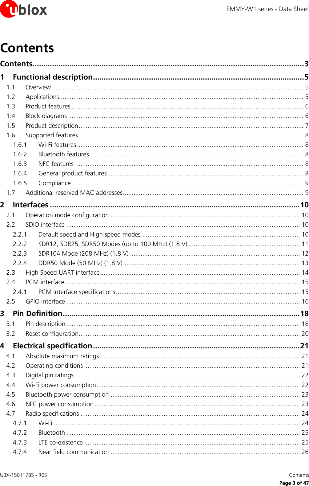
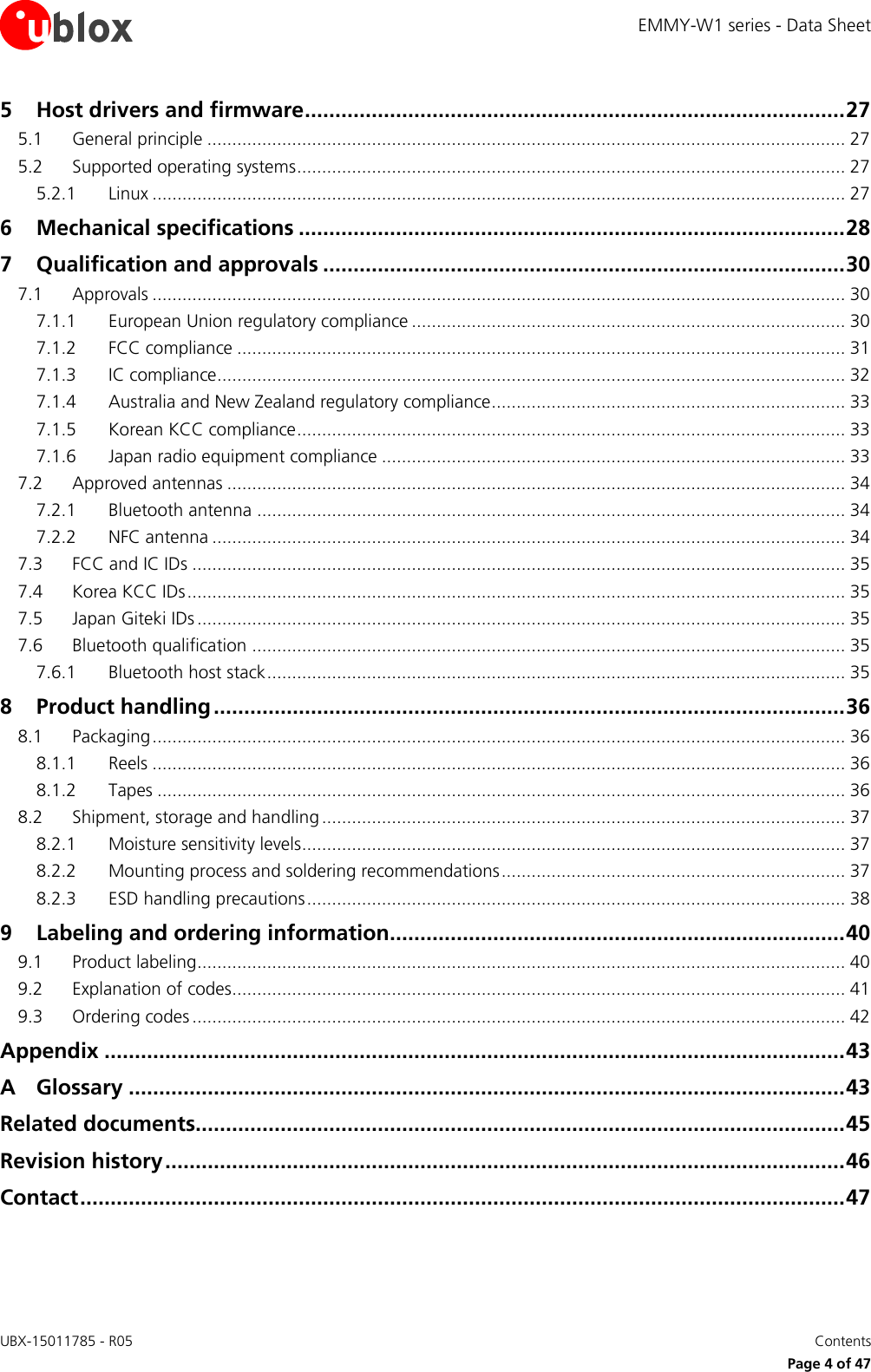
Contents
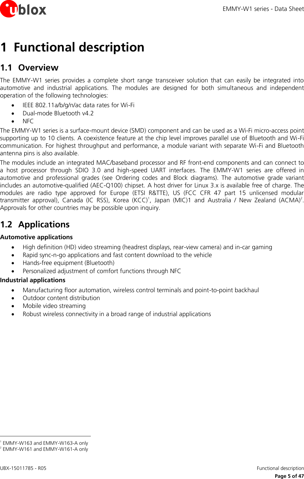
1.
EMMY-W1_User_Manual
2.
Data Sheet
3.
EMMY-W1_AntennaReferenceDesign
Data Sheet
Navigation menu
Upload a User Manual
Namespaces
Wiki Guide
HTML
PDF
Info
Views
User Manual
Discussion / Help
Navigation
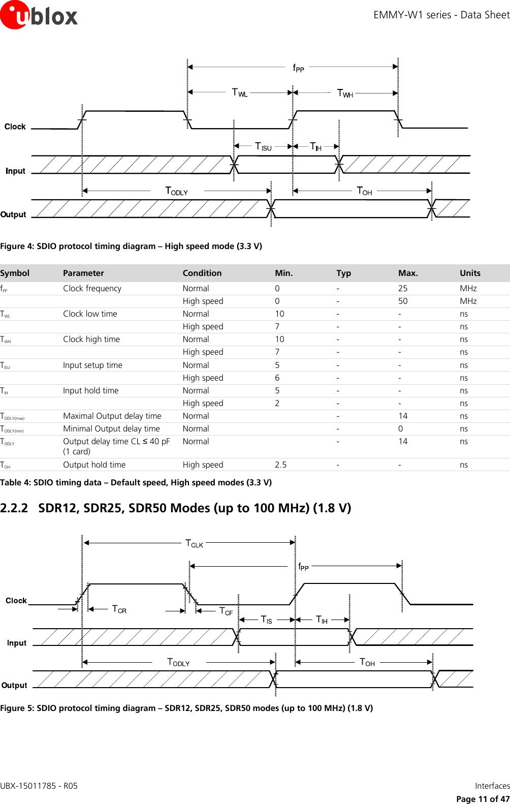
![EMMY-W1 series - Data Sheet UBX-15011785 - R05 Interfaces Page 13 of 47 2.2.4 DDR50 Mode (50 MHz) (1.8 V) Figure 7: SDIO CMD timing diagram – DDR50 mode (50 MHz) Figure 8: SDIO DAT[3:0] timing diagram – DDR50 mode (50 MHz)](https://usermanual.wiki/u-blox/EMMYW161.Data-Sheet/User-Guide-3279239-Page-13.png)
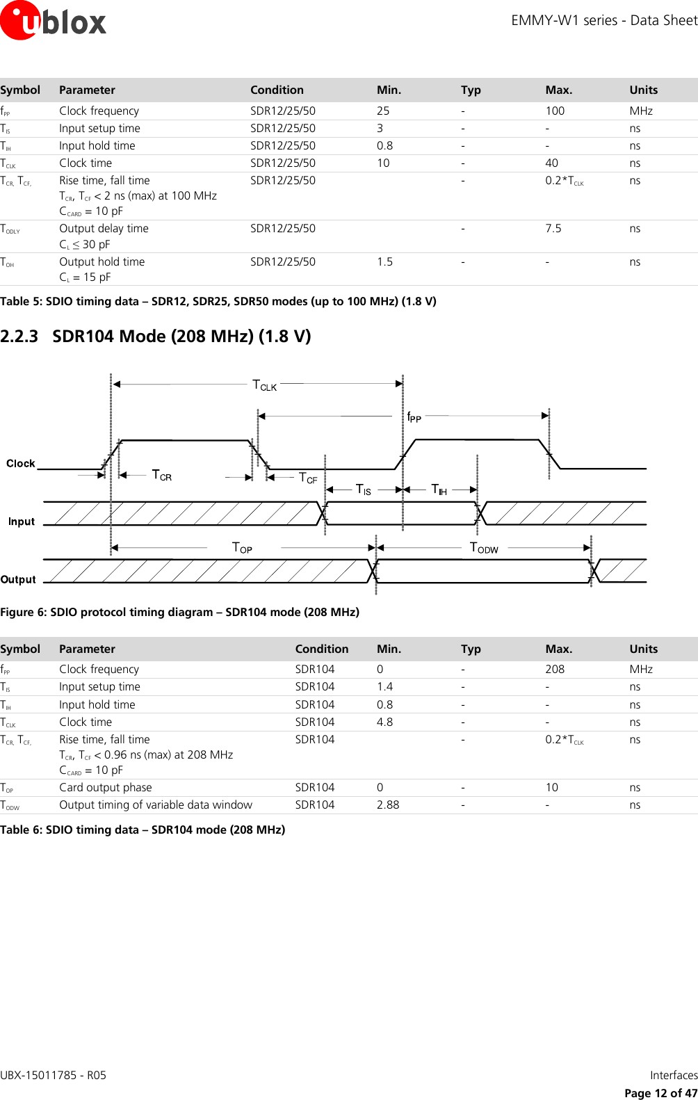
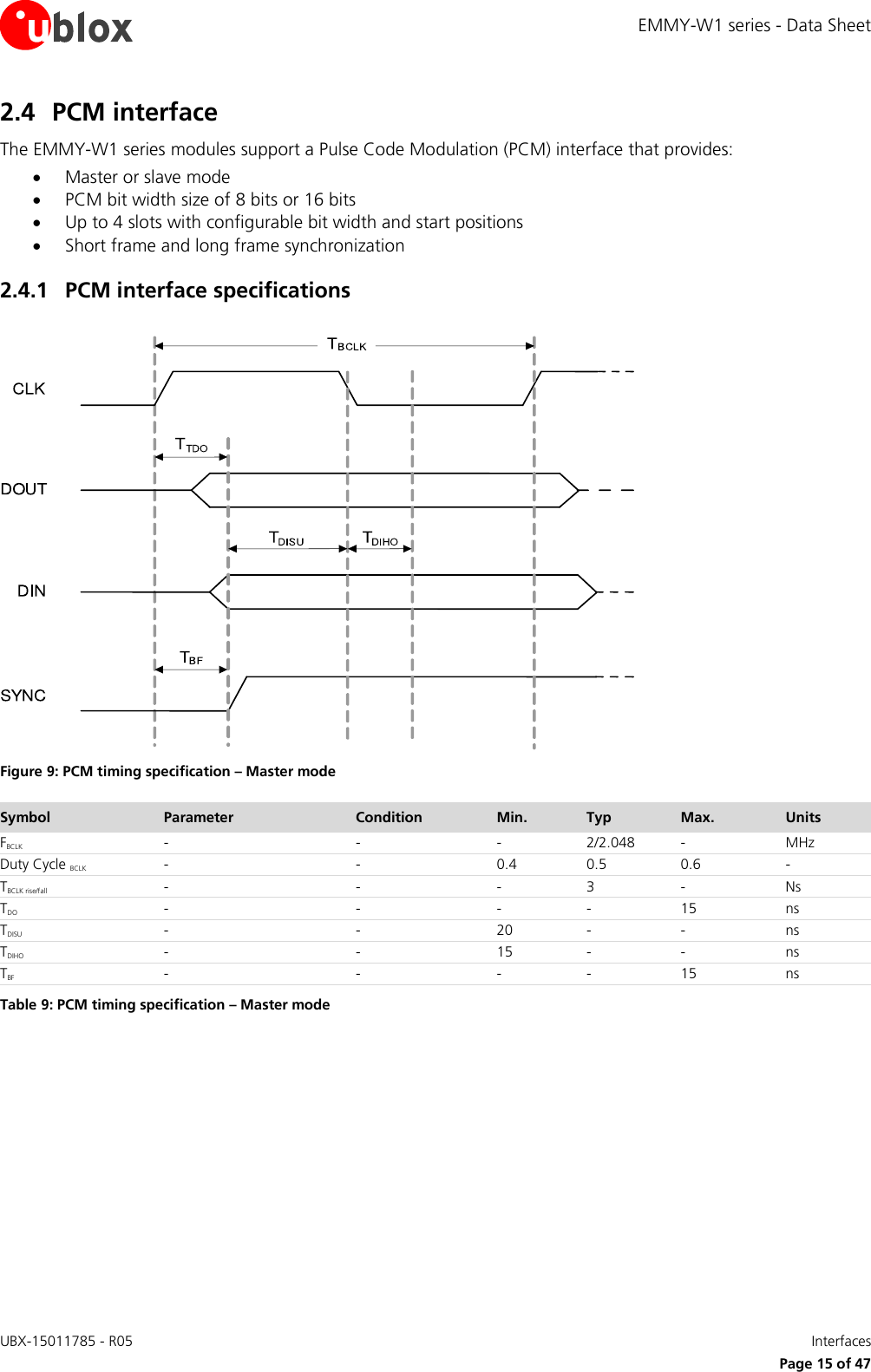
![EMMY-W1 series - Data Sheet UBX-15011785 - R05 Interfaces Page 14 of 47 Symbol Parameter Condition Min. Typ Max. Units Clock TCLK Clock time 50 MHz (max) between rising edges DDR50 20 ns TCR, TCF, Rise time, fall time TCR, TCF < 4.00 ns (max) at 50 MHz CCARD = 10 pF DDR50 0.2*TCLK ns Clock Duty DDR50 45 55 % CMD Input (referenced to clock rising edge) TIS Input setup time CCARD ≤ 10 pF (1 card) DDR50 6 ns TIH Input hold time CCARD ≤ 10 pF (1 card) DDR50 0.8 ns CMD Output (referenced to clock rising edge) TODLY Output delay time during data transfer mode CL ≤ 30 pF (1 card) DDR50 13.7 ns TOHLD Output hold time CL ≥ 15 pF (1 card) DDR50 1.5 ns DAT[3:0] Input (referenced to clock rising and falling edges) TIS2x Input setup time CCARD ≤ 10 pF (1 card) DDR50 3 ns TIH2x Input hold time CCARD ≤ 10 pF (1 card) DDR50 0.8 ns DAT[3:0] Output (referenced to clock rising and falling edges) TODLY2x (max) Output delay time during data transfer mode CL ≤ 25 pF (1 card) DDR50 7.0 ns TODLY2x (min) Output hold time CL ≥ 15 pF (1 card) DDR50 1.5 ns Table 7: SDIO timing data – DDR50 mode (50 MHz) 2.3 High Speed UART interface The EMMY-W1 series modules support a high speed Universal Asynchronous Receiver/Transmitter (UART) interface in compliance with the industry standard 16550 specification. The main features of the UART interface are: FIFO mode permanently selected for transmit and receive operations 2 pins for transmit and receive operations 2 flow control pins Interrupt triggers for low-power, high throughput operation High throughput (4 Mbps) The UART interface operation includes: Uploading the firmware to the module Supporting data input/output operation for peripheral devices connected through a standard UART interface Baud Rate 1200 38400 460800 1500000 3000000 2400 57600 500000 1843200 3250000 4800 76800 921600 2000000 3692300 9600 115200 1000000 2100000 4000000 19200 230400 1382400 2764800 Table 8: Supported UART Baud rates](https://usermanual.wiki/u-blox/EMMYW161.Data-Sheet/User-Guide-3279239-Page-14.png)
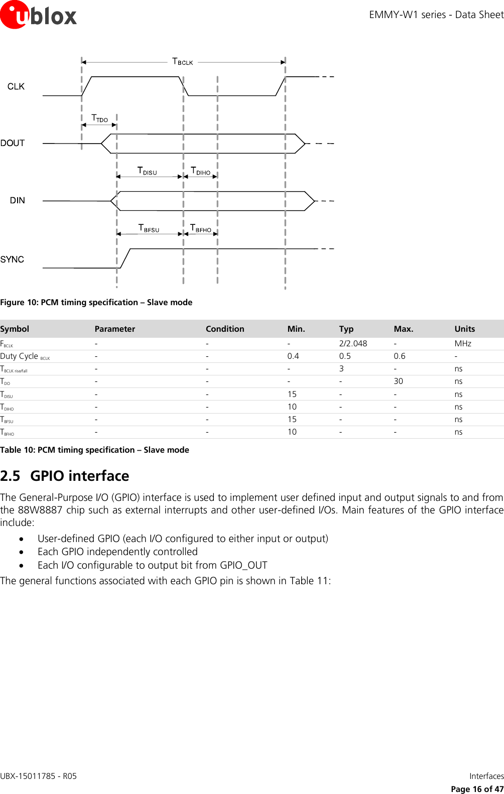
![EMMY-W1 series - Data Sheet UBX-15011785 - R05 Interfaces Page 17 of 47 GPIO Function GPIO Pin 0 1 2 3 4 5 6 7 8 9 10 11 14 15 16 17 General Input X X X X X X X X X X X X X X X X Output X X X X X X X X X X X X X X X X LEDs7 LED output8 - - X X - - - - - - - - - - - - Interrupts Input X X X X X X X X X X X X X X X X Table 11: GPIO Functions – GPIO [17:14], [11:0] GPIO_12 and GPIO_13 are not available. 7 The possibility to use as an LED output depends on the firmware and driver version. 8 GPIO [2] is used for Wi-Fi activity while GPIO [3] is used for Bluetooth activity.](https://usermanual.wiki/u-blox/EMMYW161.Data-Sheet/User-Guide-3279239-Page-17.png)
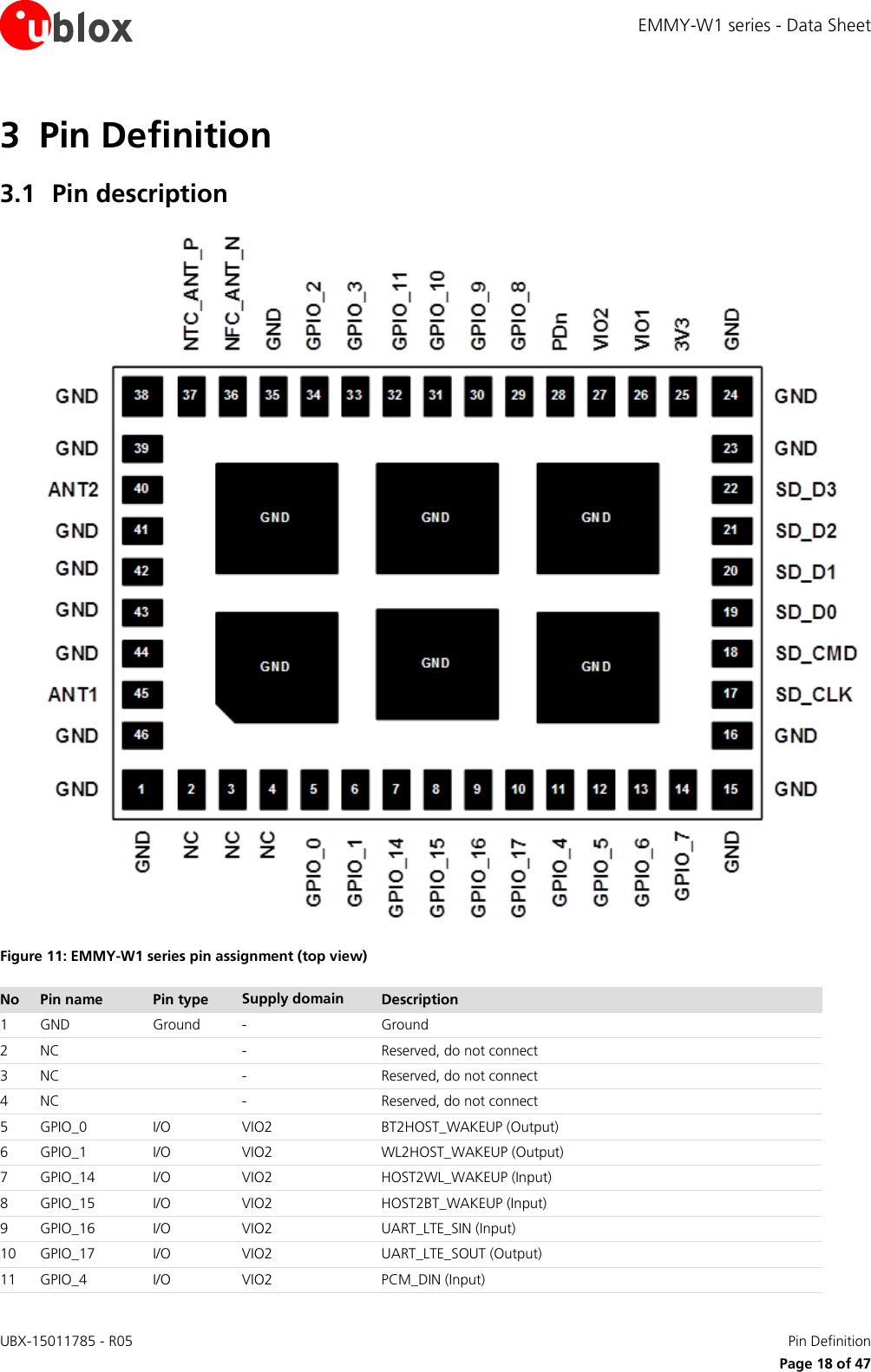
![EMMY-W1 series - Data Sheet UBX-15011785 - R05 Pin Definition Page 19 of 47 No Pin name Pin type Supply domain Description 12 GPIO_5 I/O VIO2 PCM_DOUT (Output) 13 GPIO_6 I/O VIO2 PCM_CLK (Input if slave, Output if master) 14 GPIO_7 I/O VIO2 PCM_SYNC (Input if slave, Output if master) 15 GND Ground - Ground 16 GND Ground - Ground 17 SD_CLK I VIO1 SDIO Clock input 18 SD_CMD I/O VIO1 SDIO Command line 19 SD_D0 I/O VIO1 SDIO Data line bit [0] 20 SD_D1 I/O VIO1 SDIO Data line bit [1] 21 SD_D2 I/O VIO1 SDIO Data line bit [2] 22 SD_D3 I/O VIO1 SDIO Data line bit [3] 23 GND Ground - Ground 24 GND Ground - Ground 25 3V3 Power 3.3V 3.3V Power supply (2.97 V - 3.63 V) 26 VIO1 Power VIO1 VIO1 Power supply (1.62V - 1.98 V, 2.97 V - 3.63 V) 27 VIO2 Power VIO2 VIO2 Power supply (1.62V - 1.98 V, 2.97 V - 3.63 V) 28 PDn Input - Full power down(active low)9 29 GPIO_8 I/O VIO2 UART_SOUT (Output) 30 GPIO_9 I/O VIO2 UART_SIN (Input) 31 GPIO_10 I/O VIO2 UART_CTSn (Input) 32 GPIO_11 I/O VIO2 UART_RTSn (Output) 33 GPIO_3 I/O 3.3V LED_OUT_BT (Output) - BT indicator, Configuration pin10, PCM_MCLK (output if master, input if slave) 34 GPIO_2 I/O 3.3V LED_OUT_WLAN (Output) - WLAN indicator, Configuration pin10 35 GND Ground - Ground 36 NFC_ANT_N I/O, RF 3.3V NFC Coil Antenna, negative I/O pin 37 NFC_ANT_P I/O, RF 3.3V NFC Coil Antenna, positive I/O pin 38 GND Ground - Ground 39 GND Ground - Ground 40 ANT2 I/O, RF - Bluetooth antenna only in case of EMMY-W163 module. Not connected in case of EMMY-W161 or EMMY-W165 module11 41 GND Ground - Ground 42 GND Ground - Ground 43 GND Ground - Ground 44 GND Ground - Ground 45 ANT1 I/O, RF - Wi-Fi + Bluetooth antenna in case of single-antenna module. Wi-Fi antenna only in case of dual-antenna module11 46 GND Ground - Ground - Exposed pin Ground - Six Ground/Thermal exposed pins, connect to the ground Table 12: EMMY-W1 series pin description 9 High input impedance pin for minimizing shutdown current consumption. The pin shall be driven by the host controller or/and connected via 51 kΩ (or less) pull-up resistor to the 3.3 V supply rail. 10 Possible to use as an LED output depending on the firmware and driver version. In this case, the module pin acts as an open drain output and the whole LED circuitry must be supplied from 3.3 V power line. A LED current limiting resistor should be used; maximum sink current to the ground is 10 mA. These pins can also be used for host interface configuration. See Operation mode configuration section. 11 Pin protected from the static electricity by internal DC feed to the ground.](https://usermanual.wiki/u-blox/EMMYW161.Data-Sheet/User-Guide-3279239-Page-19.png)
![EMMY-W1 series - Data Sheet UBX-15011785 - R05 Electrical specification Page 21 of 47 4 Electrical specification Stressing the device above one or more of the ratings listed in the Absolute Maximum Rating section may cause permanent damage. These are stress ratings only. Operating the module at these or at any conditions other than those specified in the Operating conditions section (section 4.2) of the specification should be avoided. Exposure to Absolute Maximum Rating conditions for extended periods may affect device reliability. Operating condition ranges define those limits within which the functionality of the device is guaranteed. Where application information is given, it is advisory only and does not form part of the specification. 4.1 Absolute maximum ratings Symbol Description Min. Typ Max. Units 3V3 Power supply voltage 3.3 V - 3.3 4.0 V VIO1 I/O supply voltage 1.8 V 1.8 2.2 V I/O supply voltage 3.3 V 3.3 4.0 V VIO2 I/O supply voltage 1.8 V - 1.8 2.2 V I/O supply voltage 3.3 V 3.3 4.0 V TSTORAGE Storage temperature -40 +85 ºC Table 13: Absolute maximum ratings The product is not protected against overvoltage or reversed voltages. If necessary, voltage spikes exceeding the power supply voltage specification given in table above must be limited to values within the specified boundaries by using appropriate protection devices. 4.2 Operating conditions Symbol Parameter Min. Typ Max. Units 3V3 Power supply voltage 3.3 V 2.97 3.3 3.63 V VIO1 I/O supply voltage 1.8V/3.3 V 1.62 1.8 1.98 V 2.97 3.3 3.63 V VIO2 I/O supply voltage 1.8V/3.3 V 1.62 1.8 1.98 V 2.97 3.3 3.63 V VDD_NFC NFC antenna input voltage (pins NFC_ANT_P/N) - - 3.6 V IANT_NFC NFC antenna peak input current (pins NFC_ANT_P/N)) - - 400 mA TA Ambient operating temperature -40 - +85 ºC Ripple Noise Peak-to-peak voltage ripple on 3V3, VIO1 or VIO2 supply line. The values have been determined in a frequency range from 10 KHz to > 2 MHz [3]. 20 - mV Table 14: Operating conditions Parameter Min. Typ Max. Units Storage temperature -40 +85 ºC Operation temperature -40 +85 ºC Table 15: Temperature range](https://usermanual.wiki/u-blox/EMMYW161.Data-Sheet/User-Guide-3279239-Page-21.png)
![EMMY-W1 series - Data Sheet UBX-15011785 - R05 Electrical specification Page 26 of 47 BAW decrease influence to LTE as well The BAW-Filter is included only in the EMMY-W161 module variant. 4.7.4 Near field communication 4.7.4.1 Card emulator specifications Parameter Condition Minimum Type Maximum Units AC characteristics VsensPICC Input carrier detection level, full-power mode, peak sinus differential voltage on NFC_ANT_P/N pin - 300 - mVpeak MODPICC Input ASK modulation index15 8 - 100 % DRPICC Input data rate (coding depending on standard: Manchester, Modified, Miller, or NRZ 106 - 848 Kbps Table 29: NFC card emulator For typical recommended operating conditions unless otherwise specified. 4.7.4.2 Reader/Writer specifications Parameter Condition Minimum Type Maximum Units DC characteristics VCMTX_PA Power amplifier output common mode level - VDDTX/2 - V AC characteristics FTXCARR Output carrier frequency 13.553 13.56 13.567 MHz ROUT_ANT Power amplifier output impedance - 50 - Ω MODPCD Output ASK modulation index15 8 - 100 % Table 30: NFC Reader/Writer specifications For typical recommended operating conditions unless otherwise specified 15 As defined in ISO/IEC 14443-2, for example, [a-b]/[a+b] where a and b are the peak and minimum signal amplitude respectively.](https://usermanual.wiki/u-blox/EMMYW161.Data-Sheet/User-Guide-3279239-Page-26.png)
![EMMY-W1 series - Data Sheet UBX-15011785 - R05 Host drivers and firmware Page 27 of 47 5 Host drivers and firmware 5.1 General principle The EMMY-W1 series module does not contain any persistent software. A firmware binary will be downloaded by the host operating system driver on system start-up. 5.2 Supported operating systems 5.2.1 Linux Linux device drivers are available from u-blox. Once you sign the Limited Use License Agreement (LULA) with u-blox, a driver package will be available. This package includes: • Dedicated Kernel driver, to bind the Wi-Fi, Bluetooth and NFC block to the kernel. The sources of those drivers will be provided. • A dedicated firmware image, which will be uploaded during initialization. • Various configuration tools • Laboratory and manufacturing tools For a detailed description of the driver packages, refer to EMMY-W1 series System Integration Manual [3].](https://usermanual.wiki/u-blox/EMMYW161.Data-Sheet/User-Guide-3279239-Page-27.png)
![EMMY-W1 series - Data Sheet UBX-15011785 - R05 Mechanical specifications Page 28 of 47 6 Mechanical specifications Figure 12: EMMY-W1 series dimensions (bottom view) Parameter Description Typical Tolerance A Module Length [mm] 19.8 (779.5 mil) +0.35/-0.1 (+13.8/-3.9 mil) B Module Width [mm] 13.8 (543.3 mil) +0.1/-0.1 (+3.9/-3.9 mil) C Module Thickness [mm] 2.5 (98.4 mil) +0.2/-0.2 (+7.9/-7.9 mil) ccc Seating Plane Coplanarity [mm] 0.15 (5.9 mil) D PCB Edge to Pin Edge [mm] 0.3 (11.8 mil) +0.20/-0.20 (+7.9/-7.9 mil) E Pin Width [mm] 0.8 (31.5 mil) +0.05/-0.05 (+2.0/-2.0 mil) F Pin Length [mm] 1.2 (47.2 mil) +0.05/-0.05 (+2.0/-2.0 mil) G Pin to Pin Pitch [mm] 1.25 (49.2 mil) +0.02/-0.02 (+0.8/-0.8 mil) H Horizontal Corner Pin to Pin Pitch [mm] 1.5 (59.1 mil) +0.02/-0.02 (+0.8/-0.8 mil) I Lateral Corner Pin to Pin Pitch [mm] 1.65 (65.0 mil) +0.02/-0.02 (+0.8/-0.8 mil) J Horizontal Thermal Pads Pitch [mm] 4.9 (192.9 mil) +0.02/-0.02 (+0.8/-0.8 mil)](https://usermanual.wiki/u-blox/EMMYW161.Data-Sheet/User-Guide-3279239-Page-28.png)
![EMMY-W1 series - Data Sheet UBX-15011785 - R05 Mechanical specifications Page 29 of 47 Parameter Description Typical Tolerance K Thermal Pad Height [mm] 3.35 (131 9 mil) +0.1/-0.1 (+3.9/-3.9 mil) L Thermal Pad Length [mm] 3.7 (145.7 mil) +0.1/-0.1 (+3.9/-3.9 mil) M Thermal Pad Pin 1 Mark Chamfer [mm] 0.6 x 45° (23.6 mil x 45°) +0.1/-0.1 (+3.9/-3.9 mil) N Horizontal Pin to Thermal Pad Pitch [mm] 3.725 (146.7 mil) +0.05/-0.05 (+2.0/-2.0 mil) O Lateral Pin to Thermal Pad Distance [mm] 4.1 (161.4 mil) +0.05/-0.05 (+2.0/-2.0 mil) P Lateral Thermal Pads Pitch [mm] 4.55 (179.1 mil) +0.02/-0.02 (+0.8/-0.8 mil)](https://usermanual.wiki/u-blox/EMMYW161.Data-Sheet/User-Guide-3279239-Page-29.png)
![EMMY-W1 series - Data Sheet UBX-15011785 - R05 Qualification and approvals Page 30 of 47 7 Qualification and approvals Table 31 provides an overview of the available radio type approvals for each EMMY-W1 product variant. Country/Region EMMY-W161 EMMY-W161-A EMMY-W163 EMMY-W163-A EMMY-W165 EMMY-W165-A EU (ETSI) Yes Yes Yes Yes Yes Yes USA (FCC) Yes Yes Yes Yes Yes Yes Canada (IC) Yes Yes Yes Yes Yes Yes Australia (ACMA) Yes Yes No No No No Korea (KCC) No No Yes Yes No No Japan (Giteki) No No Yes Yes No No Table 31: Overview of certifications for EMMY-W1 module series 7.1 Approvals16 Products marked with this lead-free symbol on the product label comply with the "Directive 2002/95/EC of the European Parliament and the Council on the Restriction of Use of certain Hazardous Substances in Electrical and Electronic Equipment" (RoHS). EMMY-W1 series Wi-Fi modules are RoHS compliant. 7.1.1 European Union regulatory compliance Information about regulatory compliance of the European Union for EMMY-W1 modules is available in the EMMY-W1 Declaration of Conformity [4]. 7.1.1.1 Equipment classes A multi-radio module is classified as class-1 or class-2 radio equipment depending on the frequency band in which it can operate. This equipment class is inherited by the end-product that integrates the module, thus it must be marked accordingly. Class-1 radio equipment can be placed on the market and put into service without restrictions. (Article 1 of Commission Decision 2000/299/EC of April 6 2000) This multi-radio module is defined as class-1 radio equipment when it is restricted to operate in the following frequency bands: Bluetooth , ISM band 2400 – 2483.5 MHz WLAN, ISM band 2400 – 2483.5 MHz WLAN, U-NII band-2e 5470 – 5725 MHz, exludes 5600-5650 GHz17 Class-2 radio equipment includes restrictions applied by Member States as indicated in Article 1(2) of the Commission Decision. This class uses the “Alert Sign” as an equipment class identifier. Figure 13: Alert sign to identify equipment Class-2 16 See Table 31 for information on what certifications are completed for each of the EMMY-W1 module versions. 17 Channels 118, 120, 122, 124, 126 and 128 have to be excluded for the EMMY-W1 series modules. The firmware was not approved to operate in frequencies between 5.600 – 5.650 GHz due to lack of CCA time of 10 min. This might change in future firmware releases.](https://usermanual.wiki/u-blox/EMMYW161.Data-Sheet/User-Guide-3279239-Page-30.png)
![EMMY-W1 series - Data Sheet UBX-15011785 - R05 Qualification and approvals Page 31 of 47 If an end product allows the multiradio module to operate in the 5150-5350 MHz band (WLAN channel: 36-64), it is defined as class-2 radio equipment and must be marked accordingly. Class-2 radio equipment must have the "alert" sign affixed on the equipment, packaging and printed in the user manual. The EMMY-W1 multiradio module uses harmonized frequency bands thus it is comprised by subclass H01 of class 2 equipment, for which notification in accordance with article 6(4) of the R&TTE directive is not necessary. A definition of subclasses of Class 2 equipment can be found in [15]. The table below shows the restrictions when operating WLAN at different bands within the European countries: Band Channel number Channel frequency [MHz] Indoor use allowed Outdoor use allowed Radio Equipment Class Max. EIRP ISM 1 – 11 2412 – 2462 Yes Yes 1 100 mW / 20 dBm U-NII 1 36 – 48 5180 – 5240 Yes No 2 200 mW / 23 dBm U-NII 2 52 – 64 5260 – 5320 Yes No 2 200 mW / 23 dBm U-NII 2e 100 – 14017 5500 – 5700 Yes Yes 1 1 W / 30 dBm U-NII 3 149 - 165 5750 - 5825 Yes Yes 1 25 mW / 14 dBm Table 32: Operating restrictions and radio equipment classification of EMMY-W1 series Guidance on how the end product is marked in accordance with the R&TTE directive can be found in the Radio and Telecommunication Terminal Equipment (R&TTE) Directive [15]. IMPORTANT: The ”CE” marking must be affixed on a visible location on the OEM product in which this module is installed and has to be labeled in accordance to R&TTE Directive 1999/5/EC. 7.1.2 FCC compliance The EMMY-W1 series module complies with Part 15 of the FCC Rules. Operation is subject to the following two conditions: 1. This device may not cause harmful interference, and 2. This device must accept any interference received, including interference that may cause undesired operation. Non-authorized modification could void authority to use this equipment. The internal / external antenna(s) used for this module must provide a separation distance of at least 20 cm from all persons and must not be co-located or operating in conjunction with any other antenna or transmitter. In accordance with 47 CFR § 15.19, the end product into which this module is integrated shall bear the following statement in a conspicuous location on the device: This device complies with Part 15 of the FCC Rules. Operation is subject to the following two conditions: 1. This device may not cause harmful interference, and 2. This device must accept any interference received, including interference that may cause undesired operation. When the end-product is so small or for such use that it is not practical to place the above statement on it, the information shall be placed in a prominent location in the instruction manual or pamphlet supplied to the user or on the container in which the device is marketed. However, the FCC ID label must be displayed on the device. If the end-product will be installed in locations where the end-user is not able to see the FCC ID and/or this statement, the FCC ID and the statement shall also be included in the end-product manual. The outside of final products containing the EMMY-W1 module must display in a user accessible area a label referring to the enclosed module. This exterior label can use wording such as the following: “Contains Transmitter Module FCC ID: (XYZ)(UPN)” or “Contains FCC ID: (XYZ)(UPN)”, where (XYZ) represents the](https://usermanual.wiki/u-blox/EMMYW161.Data-Sheet/User-Guide-3279239-Page-31.png)
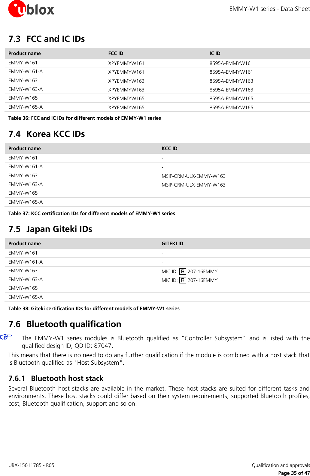
![EMMY-W1 series - Data Sheet UBX-15011785 - R05 Qualification and approvals Page 33 of 47 L’étiquette d’homologation d’Industrie Canada d’un module donné doit être posée sur l’appareil hôte à un endroit bien en vue en tout temps. En l’absence d’étiquette, l’appareil hôte doit porter une étiquette sur laquelle figure le numéro d’homologation du module d’Industrie Canada, précédé des mots « Contient un module d’émission », ou du mot « Contient », ou d’une formulation similaire allant dans le même sens et qui va comme suit : « Contient le module d’émission IC: (CN)-(UPN) », où (CN) représente le numéro de compagnie, attribué par Industrie Canada et (UPN) représente le numéro de produit unique attribué par le requérant. The internal / external antenna(s) used for this module must provide a separation distance of at least 20 cm from all persons and must not be co-located or operating in conjunction with any other antenna or transmitter. See Table 33 for list of approved antennas. The approval type for all the EMMY-W1 series variants is a modular approval. Due to Industry Canada Modular Approval Requirements (Source: RSP-100 Issue 10), any application which includes the module must be approved by the module manufacturer (u-blox). The application manufacturer must provide design data for the review procedure. 7.1.4 Australia and New Zealand regulatory compliance The EMMY-W1 series modules are compliant with the standards made by the Australian Communications and Media Authority (ACMA). For detailed information about the obligations for end products market in Australia or New Zealand, refer to the EMMY-W1 series System Integration Manual [3]. 7.1.5 Korean KCC compliance MSIP-CRM-ULX-EMMY-W163 The EMMY-W1 series modules are certified by the Korea Communications Commission (KCC). 7.1.6 Japan radio equipment compliance The EMMY-W1 series module complies with the Japanese Technical Regulation Conformity Certification of Specified Radio Equipment (ordinance of MPT N°. 37, 1981), Article 2, Paragraph 1: Item 19 "2.4 GHz band wide band low power data communication system" Item 19-3 “Low power data communications system in the 5.2/5.3 GHz band” Item 19-3-2 “Low power data communications system in the 5.6 GHz band” The EMMY-W1 series module is restricted on the Japanese market to be used indoors only if the product is operating in the 5.2/5.3 GHz band. 207-16EMMY 5GHz band (W52,W53): For indoor use only - この製品は屋内においてのみ使用可能です Figure 14 Giteki mark for the EMMY-W1 series modules.](https://usermanual.wiki/u-blox/EMMYW161.Data-Sheet/User-Guide-3279239-Page-33.png)
![EMMY-W1 series - Data Sheet UBX-15011785 - R05 Qualification and approvals Page 34 of 47 7.2 Approved antennas For Bluetooth and Wi-Fi operation in the 2.4 GHz band and Wi-Fi operation in the 5 GHz band, the module has been tested and approved for use with the antennas listed in Table 33. Manufacturer Part Number Antenna type Peak gain [dBi] 2.4 GHz band 5 GHz band Antenova A10194 SMD chip antenna 10x10x0.9 [mm] [5] 1.8 4.1 Linx ANT-DB1-RAF-RPS Dual-band dipole antenna [6] 2.5 4.6 Taoglas GW.40.2153 Dual-band dipole antenna [7] 3.74 2.5 Taoglas GW.59.3153 Dual-band dipole antenna [8] 2.37 2.93 Walsin RFDPA870900SBLB8G1 Dual-band dipole antenna [9] 2 3 Delock 88395 Dual-band dipole antenna [11] 1.5 2.1 Table 33: List of approved dual-band antennas The module can be integrated with other antennas which the OEM installer must authorize with respective regulatory agencies and after approval of the module manufacturer. Important: To be compliant to FCC §15.407(a) the EIRP is not allowed to exceed 125 mW (21 dBm) at any elevation angle above 30 degrees as measured from the horizon when operate as an outdoor access point in U-NII-1 band, 5.150-5.250 GHz. If in doubt if the antenna installation fulfills this requirement at maximum output power, restrict the maximum output power setting for operation in the 5.150-5.250 GHz band to 16 dBm. For a description on how to configure output power settings refer to the EMMY-W1 series System Integration Manual [3]. 7.2.1 Bluetooth antenna The following antennas are designated for Bluetooth transmission on EMMY-W163: Manufacturer Part Number Antenna type Peak gain [dBi] 2.4 GHz band Johanson Technology 2450AT45A100 SMD chip antenna 10x10x0.9 [mm] [12] 2.2 Taoglas GW.26.0151 Single-band monopole antenna [13] 1.8 Linx ANT-2.4-CW-RCT-RP Single-band dipole antenna [10] 2.2 Linx ANT-2.4-CW-RH Single-band monopole antenna [14] -0.9 Table 34: List of approved single-band antennas 7.2.2 NFC antenna The following antennas are designated to be used for Near Field Communication (NFC) on EMMY-W161, EMMY-W163, and EMMY-W165: Manufacturer Part Number Antenna type u-blox EMMY_NFC_ANT External PCB antenna with connector Table 35: List of approved NFC antenna](https://usermanual.wiki/u-blox/EMMYW161.Data-Sheet/User-Guide-3279239-Page-34.png)
![EMMY-W1 series - Data Sheet UBX-15011785 - R05 Product handling Page 36 of 47 8 Product handling 8.1 Packaging The EMMY-W1 series modules are delivered as hermetically sealed tape and reels, to enable efficient production, production lot set-up and tear-down. For more information about packaging, see the u-blox Package Information Guide [1]. 8.1.1 Reels The EMMY-W1 series modules are deliverable in quantities of 500 pieces on a reel. The EMMY-W1 series modules are shipped on reel Type A as described in the u-blox Package Information Guide [1]. 8.1.2 Tapes Figure 14 shows the position and orientation of the EMMY-W1 modules as they are delivered on tape. The dimensions of the tapes are specified in Figure 16. Figure 15: Orientation for EMMY-W1 modules on tape Feed direction Sprocket Hole Pin 1](https://usermanual.wiki/u-blox/EMMYW161.Data-Sheet/User-Guide-3279239-Page-36.png)
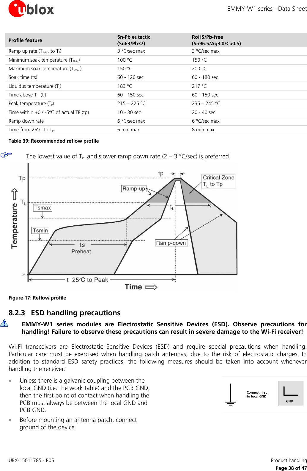
![EMMY-W1 series - Data Sheet UBX-15011785 - R05 Product handling Page 37 of 47 Figure 16: EMMY-W1 Tape dimensions 8.2 Shipment, storage and handling For more information regarding shipment, storage and handling see the u-blox Package Information Guide [1]. 8.2.1 Moisture sensitivity levels The EMMY-W1 series modules are rated at moisture sensitivity level 3. See moisture sensitive warning label on each shipping bag for detailed information. After opening the dry pack, modules must be mounted within 168 hours in factory conditions of maximum 30°C/60%RH or must be stored at less than 10%RH. Modules require baking if the humidity indicator card shows more than 10% when read at 23±5°C or if the conditions mentioned above are not met. Please refer to J-STD-033B standard for bake procedure. 8.2.2 Mounting process and soldering recommendations The EMMY-W1 series module is a surface mount module supplied on a 4-layer FR4-type PCB with gold plated connection pins and produced in a lead-free process with a lead-free soldering paste. The wrap page of the PCB is max. 0,75% according to IPC-A-610E. The thickness of solder resist on the host PCB top side and the EMMY-W1 bottom side must be considered for the soldering process. This module is compatible with industrial reflow profile for RoHS/Pb-free solders, Sn96.5/Ag3.0/Cu0.5 solder is a right choice. Use of "No Clean" soldering paste is strongly recommended, cleaning the populated modules is strongly discouraged - residuals under the module cannot be easily removed with any cleaning process. Cleaning with water can lead to capillary effects where water is absorbed into the gap between the host board and module. The combination of soldering flux residuals and encapsulated water could lead to short circuits between neighboring pins. Only a single reflow soldering process is permitted for host boards with the EMMY-W1 series modules. The reflow profile used is dependent on the thermal mass of the entire populated PCB, heat transfer efficiency of the oven and particular type of solder paste used. Since the profile used is process and layout dependent, the optimum profile should be studied case by case. Recommendations below should be taken as a starting point guide. In case of basic information necessity, please refer to J-STD-020C standard. }](https://usermanual.wiki/u-blox/EMMYW161.Data-Sheet/User-Guide-3279239-Page-37.png)
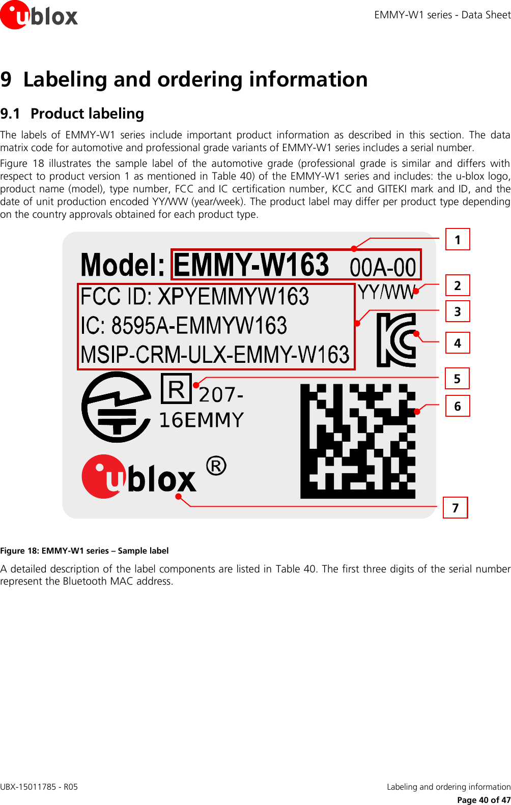
![EMMY-W1 series - Data Sheet UBX-15011785 - R05 Labeling and ordering information Page 41 of 47 Reference Description 1 Text “MODEL:” followed by product type number, excluding the second dash and smaller font used for the product version identifier (For example, “xxB-yy” for professional and “xxA-yy” for automotive grade). 2 Date of production encoded YY/WW (year/week) 3 Certification IDs (e.g. FCC/IC, KCC) with which the module has been listed with 4 KC mark for Korea KCC certification if applicable. 5 GITEKI mark and ID if applicable 6 Data Matrix with unique serial number of 19 alphanumeric symbols. The 3 first symbols represent the unique module type no: 631: EMMY-W161-00A-00 632: EMMY-W163-00A-00 700: EMMY-W163-00B-00 701: EMMY-W161-00B-00 756: EMMY-W165-00A-00 841: EMMY-W165-00B-00 The next 12 symbols represent the unique hexadecimal Bluetooth MAC address (see section 1.7 for more information about MAC addresses) of the module AABBCCDDEEFF, and the last 4 symbols represent the hardware and firmware version encoded HHFF. 7 u-blox logo, the red dot in the logo is also marking pin no 1 Table 40 EMMY-W1 series label description 9.2 Explanation of codes Two different product code formats are used. The Product Name is used in documentation such as this data sheet and identifies all u-blox products, independent of packaging and quality grade. The Ordering Code includes options and quality, while the Type Number includes the hardware and firmware versions. Table 41 below details these three different formats: Format Structure Product Name PPPP-TGVV Ordering Code PPPP-TGVV-TTQ Type Number PPPP-TGVV-TTQ-XX Table 41: Product code formats Table 42 explains the parts of the product code. Code Meaning Example PPPP Form factor EMMY TG Platform T – Dominant technology, For example, W: Wi-Fi, B: Bluetooth G - Generation W1 VV Variant based on the same platform; range [00…99] 61 TT Major Product Version 00 Q Quality grade A: Automotive B: Professional C: Standard A XX Minor product version (not relevant for certification) 00 Table 42: Part identification code](https://usermanual.wiki/u-blox/EMMYW161.Data-Sheet/User-Guide-3279239-Page-41.png)
![EMMY-W1 series - Data Sheet UBX-15011785 - R05 Related documents Page 45 of 47 Related documents [1] u-blox Package Information Guide, document number UBX-14001652 [2] Driver Software Application Note for ELLA-W1 series and EMMY-W1 series, document number UBX-15012542 [3] EMMY-W1 series System Integration Manual, document number UBX-15024929 [4] EMMY-W1 Declaration of Conformity, document number UBX-16007139 [5] Mixtus A10194 Product Specification, Antenova-M2M, http://www.antenova-m2m.com/documents/download/40c67cf2e7a4c7b8cd0f7faed7f6d2ca4fe1886d597d5, October 2015 [6] ANT-DB1-RAF-xxx Data Sheet, Linx, http://www.linxtechnologies.com/resources/data-guides/ant-db1-raf-xxx.pdf, October 2015 [7] Specification. Part No.: GW.40.2153, taoglas, https://fccid.io/pdf.php?id=2415249, December 2015 [8] Specification. Part No.: GW.59.3153, taoglas, http://www.taoglas.com/images/product_images/original_images/GW.59.3153- 2.4GHz-5.8GHz Band Mount Dipole Antenna 080910.pdf, October 2015 [9] 2015 RF Devices and High Frequency Inductors Product catalog, http://www.passivecomponent.com/document/HF_Devices/2013RF_Catalogue.pdf, December 2015 [10] ANT-2.4-CW-RCT-xx Data Sheet, Linx, http://www.linxtechnologies.com/resources/data-guides/ant-2.4-cw-rct-xx.pdf, October 2015 [11] Delock WLAN 802.11 ac/a/b/g/n Antenna RP-SMA 2 dBi Omnidirectional Joint, 2015-11-26 http://www.delock.com/produkt/88395/pdf.html?sprache=en, November 2015 [12] 2.45 GHz High Gain SMD Chip Antenna P/N 2450AT45A100, Johanson Technology, http://www.johansontechnology.com/datasheets/antennas/2450AT45A100.pdf, October 2015 [13] 2.4 GHz Miniature Screw mount Monopole Antenna, taoglas, http://www.taoglas.com/images/product_images/original_images/GW.26.0112 2.4GHz Band Monopole SMA%28M%29RA.pdf, December 2015 [14] ANT-2.4-CW-RH Data Sheet, Linx, http://www.linxtechnologies.com/resources/data-guides/ant-2.4-cw-rh-xxx.pdf, December 2015 [15] Radio and Telecommunication Terminal Equipment (R&TTE) Directive; http://ec.europa.eu/growth/sectors/electrical-engineering/rtte-directive; July 2016 For regular updates to u-blox documentation and to receive product change notifications, register on our homepage (http://www.u-blox.ch/).](https://usermanual.wiki/u-blox/EMMYW161.Data-Sheet/User-Guide-3279239-Page-45.png)