u blox WIBEAR-I The Lesswire industrial universal 802.11 a/b/g WLAN + Bluetooth 2.1 module is targeted for integration into different products of OEM partners enabling them to communicate over WLAN and Bluetooth connection. User Manual WiBear engl v1 0
lesswire AG The Lesswire industrial universal 802.11 a/b/g WLAN + Bluetooth 2.1 module is targeted for integration into different products of OEM partners enabling them to communicate over WLAN and Bluetooth connection. WiBear engl v1 0
u blox >
UserMan
- 1 -
lesswire AG│Im Technologiepark 1│15236 Frankfurt (Oder)│Germany│url: www.lesswire.com
Tel.: 0700 L E S S W I R E (53 77 94 73) │Fax +49 (0) 335 56 56 - 999│e-mail: sales@lesswire.com
April 2010
Subject to technical modifications!
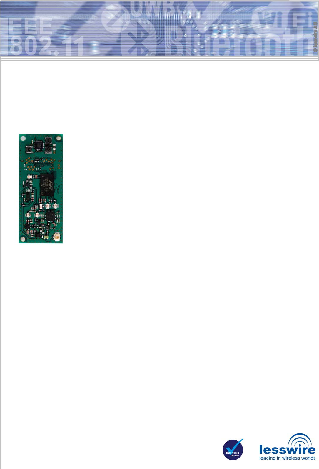
Universal embedded WLAN solution for OEM customers
WiBear - Industrial universal WLAN front end modules
(IEEE 802.11a/b/g)
The lesswire industrial universal WiBear WLAN module is a reliable, automotive grade WLAN front end
module. The module is developed for use in industrial temperature range from -40°C to +85°C.
The WiBear WLAN modules feature two key benefits:
• Two WiBear-versions are available for the communication in the 2.4GHz (WiBear/2.4GHz) and in
both 2.4 + 5 GHz (WiBear/5GHz) frequency bands. The WiBear/5GHz module allows to use addi-
tional 19 channels in the 5 GHz band outside the 2.4 GHz band, which often is crowded by other 2.4
GHz devices.
• Offers the simultaneous use of two different leading wireless standards, the IEEE 802.11a/b,g WLAN
and a full featured Bluetooth IEEE802.15.1 Class 2 transceiver.
The WiBear WLAN module may be integrated in two ways into customer solutions:
• Deploy the processor of the existing design as host controller: The WLAN module is connected to the
customer processor by SDIO or G-SPI interfaces. The WLAN stack will run on processor of the exist-
ing design.
• Add the WiBear WLAN module together with a host controller to an existing design. As an example,
the host controller may be a based on ARM9 core.
The host controller selection can consider additional needed interfaces like Ethernet, USB, CAN, or UART.
The WiBear WLAN module is designed amongst others for industrial solutions in order to connect with already existing WLAN
networks on shop floor. Furthermore, an embedded Linux-based Web Server reference application is available to easily
implement user-interfaces for WLAN module configuration.
The universal WLAN module saves time and reduces costs. OEM customers can concentrate on their core competence while
adopting this easy to use WLAN module that can enable many wireless applications. For larger quantity orders lesswire can also
provide module design-ins. Driver porting to other operating systems can be offered by lesswire.
-
WLAN
• IEEE802.11b Output power: typ. +18 dBm
Sensitivity: @ 1Mbps typ. -98 dBm
Sensitivity: @11Mbps typ. -89dBm
• IEEE802.11g Output power: typ. +15 dBm
Sensitivity: @ 6Mbps typ. -91dBm
Sensitivity: @12Mbps typ. -89dBm
Sensitivity: @54Mbps typ. -74dBm
• IEEE802.11a Output power: typ. +15dBm
Sensitivity: @ 6Mbps typ. - 90dBm
Sensitivity: @12Mbps typ. - 88dBm
Sensitivity: @54Mbps typ. - 73dBm
-
Bluetooth
• IEEE802.15.1 Output power: typ. +8dBm
-
Operating Temperature -40°C to + 85°C
-
Storage Temperature -50°C to + 125°C
-
Host Interface Connector 60 PIN Hirose DF12
• SDIO
• G-SPI
• Audio
• Bluetooth coexistence
• JTAG
• UART
• LED
Driver Support
• Linux 2.6.x
• Windows CE, Windows XP/Vista
Bluetooth support
• Bluetooth 2.1 and Enhanced Data Rate (EDR) operation
• Bluetooth stacks that support UART HCI protocol
- 2 -
lesswire AG│Im Technologiepark 1│15236 Frankfurt (Oder)│Germany│url: www.lesswire.com
Tel.: 0700 L E S S W I R E (53 77 94 73) │Fax +49 (0) 335 56 56 - 999│e-mail: sales@lesswire.com
Functions (continuation) Profile view with connector
Technical data
WLAN standards: IEEE 802.11a, b, g
IEEE 802.11i, e, j, h, s
Data transfer rate: IEEE 802.11b: 11, 5.5, 2, 1 Mbps
IEEE802.11a/g: 54, 48, 36, 24, 18,
12, 9, 6 Mbps
Frequency range: 2.4 – 2.497 GHz (ISM Band)
5.150 – 5.805 GHz (UNII Bands)
ETSI support in 5 GHz band: Transmit Power Control (TPC)
Dynamic Frequency Selection
(DFS)
Protocols: Implements Ethernet NIC
Host interfaces: SDIO (default),G- SPI alternatively
Antenna: U.FL Hirose coaxial connector
Alternatively: Onboard antenna
Mounting technology: 60 pin Hirose DF12 connector pro-
tected by three bolt connections
Management: According to IEEE802.11
LEDs: Optional, operation status.
Set by Firmware
Modulation: OFDM, DSSS/CCK
Operating temperature: -40° to 85° Celsius
(5 GHz: limited temperature range)
Power supply:
Supply current: 3.2 – 5.5V (typ. 3.3)
3.3V/350mA (max),
3.3V/300mA (avg)
Firmware: At system power-on firmware is
downloaded from host. Optionally
the firmware is stored in on-board
SPI EEPROM and updated by
JTAG interface.
Security encryption: WEP 64/128 Bit-Key, WPA (TKIP,
AES), WPA2
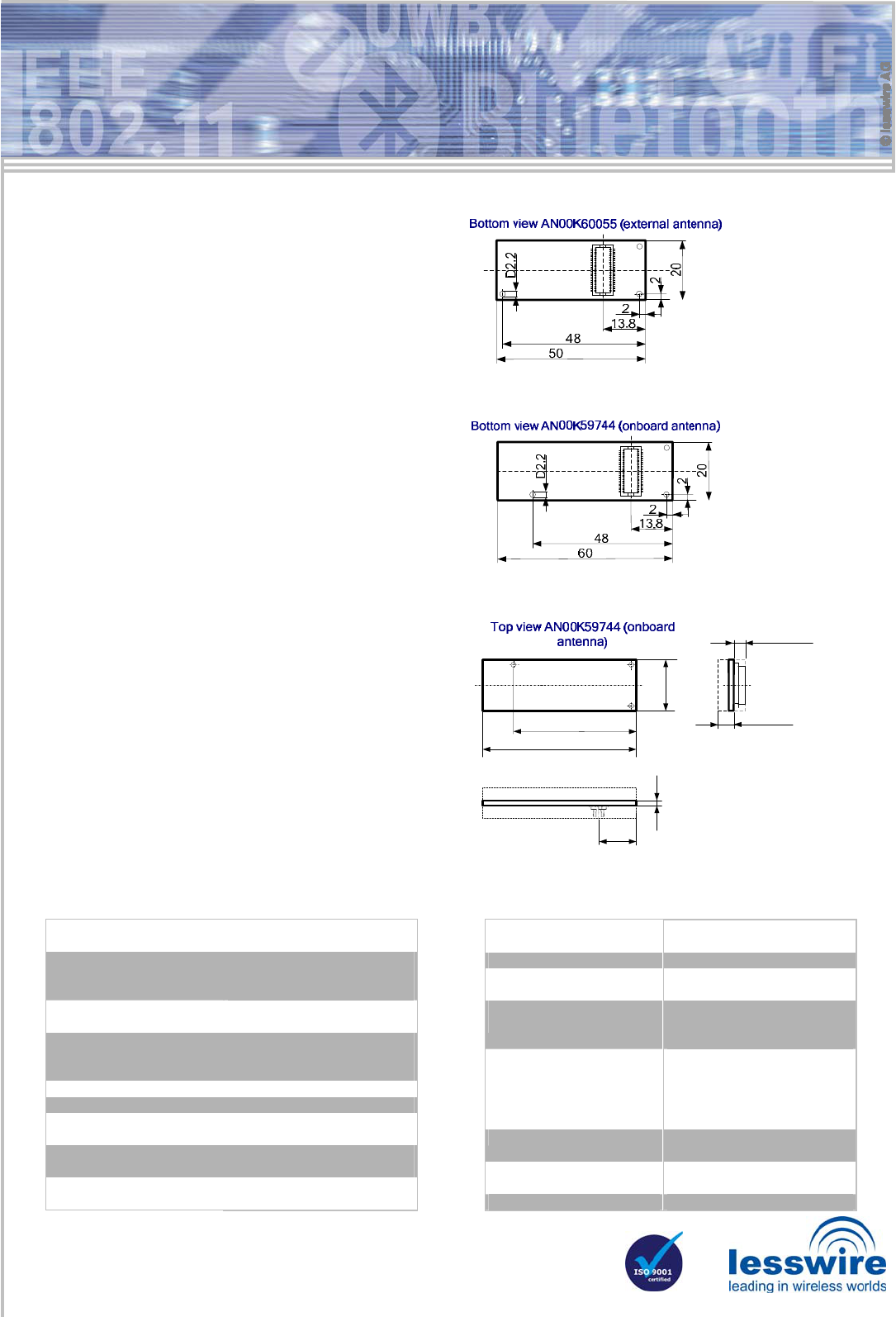
Dimensions (LxB): Onboard antenna: 60mm x 20mm
External antenna: 50mm x 20mm
Scope of delivery: Embedded WLAN module
RF properties achieved by
• integrated additional PA 2.4GHz / 5Ghz
• integrated additional LNA 2.4GHz / 5GHz
WLAN/Bluetooth coexistence feature
• Hardware based coexistence support by 2-wire, 3-wire,
or 4-wire interfaces
Firmware option for Micro Access Point operation
• Support for up to 8 WLAN stations
Antenna
• U.FL Hirose coaxial connector
Operation
• Individual application
User interface
• LEDs can be configured for showing operational status
• Embedded Linux based Web Server reference application
as configuration interface
Configuration/Programming
• Configuration over WLAN or wired interfaces based on the
host controller
• External FW storage on host or separate SPI-Flash
• Fast FW download at power-on
• FW update over JTAG
Digital interfaces to host controller
• 4bit SDIO host controller interface to WLAN module (default)
• G-SPI in slave mode: Synchronous communication with
communication processor,
• Reference design with AT91SAM9262, 10 Mbps Ethernet,
CAN, USB, and Linux 2.6.26 including BSP
and drivers available
60
120
2.8 max
2.8 max
48
13.8
- 3 -
lesswire AG│Im Technologiepark 1│15236 Frankfurt (Oder)│Germany│url: www.lesswire.com
Tel.: 0700 L E S S W I R E (53 77 94 73) │Fax +49 (0) 335 56 56 - 999│e-mail: sales@lesswire.com
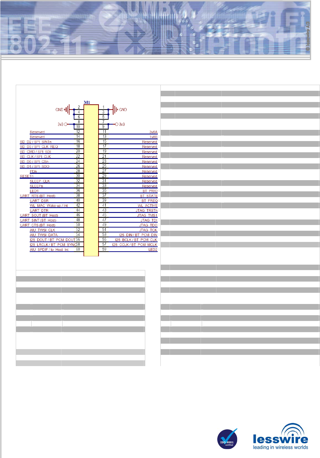
60 PIN Host Interface Connector on Motherboard Side
Power Supply
PIN Signal Description
1-6 GND Ground
7-10 VCC Module power supply 3.3V
11 3V0A Reference voltage output 3.0V
13 1V8B Reference voltage output 1.8V
SDIO- / G-SPI Interface
PIN Signal Description
16 SD_D2 / SPI_SINTn SPI_SINTn / SD_DAT[2]
18 SD_D3 / SPI_CLK_REQ SPI_CLK_REQ / SD_DAT[3]
20 SD_CMD / SPI_SDI SPI_SDI / SD_CMD
22 SD_CLK / SPI_CLK SPI_CLK / SD_CLK
24 SD_D0 / SPI_CSn SPI_SCSn / SD_DAT[0]
26 SD_D1 / SPI_SDO SPI_SDO / SD_DAT[1]
Bluetooth Coexistence
PIN Signal Description
35 BT_PRIORITY BT_PRIORITY
37 BT_STATE BT_STATE
39 BT_FREQ BT_FREQ
41 WL_ACTIVE WL_ACTIVE
Control
PIN Signal Description
28 PDn Power Down
30 RESETn Module reset
32 SLEEP_CLK Input for external sleep clock
34 SLEEPn SLEEPn Output
42 WL_MAC_Wake-up WLAN_MAC_Wake-up_Input / Interrupt_Input
Bluetooth UART (max. up to 4000000 baud)
PIN Signal Description
LED 38 UART_RTS UART_RTS_Output/ CON[15](Boot Config)
PIN Signal Description 46 UART_SOUT UART_SOUT_Output
36 LED1 LED function set by firmware 48 UART_SINT UART_SINT_Input
59 LED2 LED function set by firmware 50 UART_CTS UART_CTS_Input
JTAG
Audio Interface Unit / Inter IC Sound / Two-Wire
PIN Signal Description PIN Signal Description
43 JTAG_TRSTn TRSTn 52 GPIO_9
A
IU_TWSI_CLK /GPIO_9
45 JTAG_TMS1 TMS_SYS 54 GPIO_10
A
IU_TWSI_DATA /GPIO_10
47 JTAG_TDI TDI 60 GPIO_16 AIU_SPDIF / SoC_to_Host_Interrupt if AIU is disabled
49 JTAG_TDO TDO 53 GPIO_11 I2S_DIN / BT_PCM_DIN
51 JTAG_TCK TCK 55 GPIO_13 I2S_BCLK / BT_PCM_CLK
56 GPIO_12 I2S_DOUT / BT_PCM_DOUT
Not Bluetooth related UART Signals 57 GPIO_15 I2S_CCLK / BT_PCM_MCLK
PIN Signal Description 58 GPIO_14 I2S_LRCLK / BT_PCM_SYNC
40 UART_DSR UART_DSR_Input
44 UART_DTR UART_DTR_Output / Wi-Fi Sleep Config
- 4 -
lesswire AG│Im Technologiepark 1│15236 Frankfurt (Oder)│Germany│url: www.lesswire.com
Tel.: 0700 L E S S W I R E (53 77 94 73) │Fax +49 (0) 335 56 56 - 999│e-mail: sales@lesswire.com
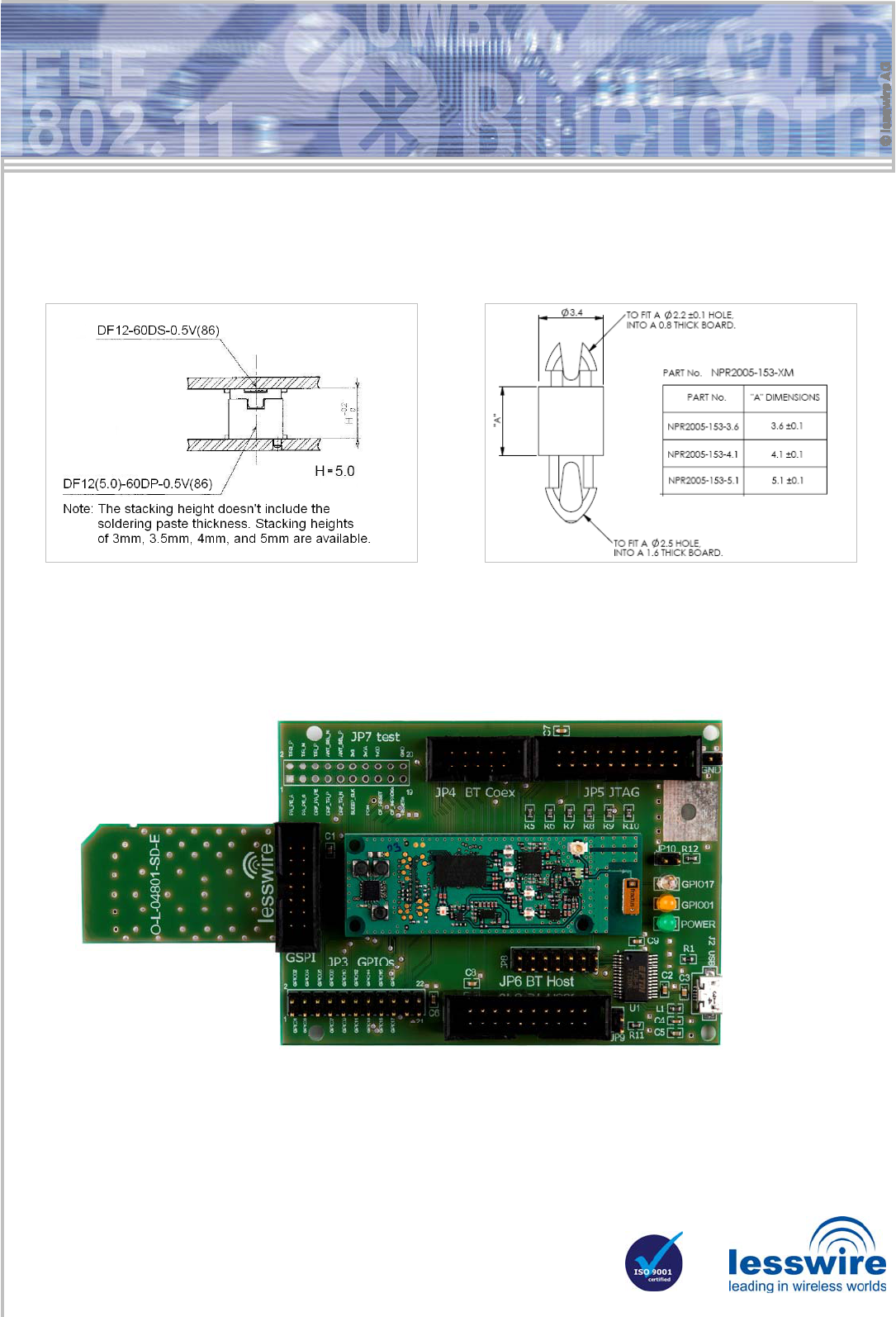
60 PIN Host Interface Connector Recommended spacers for board mounting
SDIO Development Board
The SDIO Development Board may be used to evaluate WiBear WLAN Module or to develop applications on a preferred
target platform. The target platform should be equipped by a standard SD card reader supporting SDIO in 4bit SD data
transfer mode.
SDIO Development
Board equipped with
WiBear WLAN module
AN00K59744-I with
onboard antenna.
Part numbers:
AN00K59744 WiBear-I /2.4GHz
AN00K59744 WiBear-I /5 GHz
AN00K60055 WiBear-E /2.4GHz
AN00K60055 WiBear-E /5GHz
AN00K72295 SDIO Development Board