Yamaha Tdm900r5ps1ae2 5PS 03 Service Manual Suppl User 5e01a1e2 7fd1 4893 99e4 A12bd89ed6fe
User Manual: yamaha tdm900r5ps1ae2 Yamaha Car Seat TDM900(R) 5PS1-AE2 User Guide |
Open the PDF directly: View PDF ![]() .
.
Page Count: 28

FOREWORD
This Supplementary Service Manual has been prepared to introduce new service and data for the
TDM900 (R) 2003. For complete service information procedures it is necessary to use this Supple-
mentary Service Manual together with the following manual.
TDM900 (N) 2001 SERVICE MANUAL: 5PS1-AE1
TDM900 (R) 2003
SUPPLEMENTARY
SERVICE MANUAL
E2002 by Yamaha Motor Co., Ltd.
First Edition, September 2002
All rights reserved.
Any reproduction or unauthorized use
without the written permission of
Yamaha Motor Co., Ltd.
is expressly prohibited.

NOTE:
WARNING
CAUTION:
EAS00002
NOTICE
This manual was produced by the Yamaha Motor Company, Ltd. primarily for use by Yamaha dealers
and their qualified mechanics. It is not possible to include all the knowledge of a mechanic in one manu-
al. Therefore, anyone who uses this book to perform maintenance and repairs on Yamaha vehicles
should have a basic understanding of mechanics and the techniques to repair these types of vehicles.
Repair and maintenance work attempted by anyone without this knowledge is likely to render the ve-
hicle unsafe and unfit for use.
Yamaha Motor Company, Ltd. is continually striving to improve all its models. Modifications and signifi-
cant changes in specifications or procedures will be forwarded to all authorized Yamaha dealers and
will appear in future editions of this manual where applicable.
Designs and specifications are subject to change without notice.
EAS00004
IMPORTANT INFORMATION
Particularly important information is distinguished in this manual by the following.
The Safety Alert Symbol means ATTENTION! BECOME ALERT! YOUR
SAFETY IS INVOLVED!
Failure to follow WARNING instructions could result in severe injury or death to
the motorcycle operator, a bystander or a person checking or repairing the mo-
torcycle.
A CAUTION indicates special precautions that must be taken to avoid damage
to the motorcycle.
NOTE: A NOTE provides key information to make procedures easier or clearer.

12
4
5
7
8
6
3
EAS00007
HOW TO USE THIS MANUAL
This manual is intended as a handy, easy-to-read reference book for the mechanic. Comprehensive
explanations of all installation, removal, disassembly, assembly, repair and check procedures are laid
out with the individual steps in sequential order.
1 The manual is divided into chapters. An abbreviation and symbol in the upper right corner of each
page indicate the current chapter.
Refer to “SYMBOLS”.
2 Each chapter is divided into sections. The current section title is shown at the top of each page,
except in Chapter 3 (“PERIODIC CHECKS AND ADJUSTMENTS”), where the sub-section title(s) ap-
pears.
3 Sub-section titles appear in smaller print than the section title.
4 To help identify parts and clarify procedure steps, there are exploded diagrams at the start of each
removal and disassembly section.
5 Numbers are given in the order of the jobs in the exploded diagram. A circled number indicates a
disassembly step.
6 Symbols indicate parts to be lubricated or replaced.
Refer to “SYMBOLS”.
7 A job instruction chart accompanies the exploded diagram, providing the order of jobs, names of
parts, notes in jobs, etc.
8 Jobs requiring more information (such as special tools and technical data) are described sequen-
tially.
22
1
3
5
7
9
2
4
8
6
24 25
2321
19 2018
16 1715
1413
11 12
10
GEN
INFO SPEC
ENG
FI ELEC
COOL
CHK
ADJ
TRBL
SHTG
CHAS
EAS00008
SYMBOLS
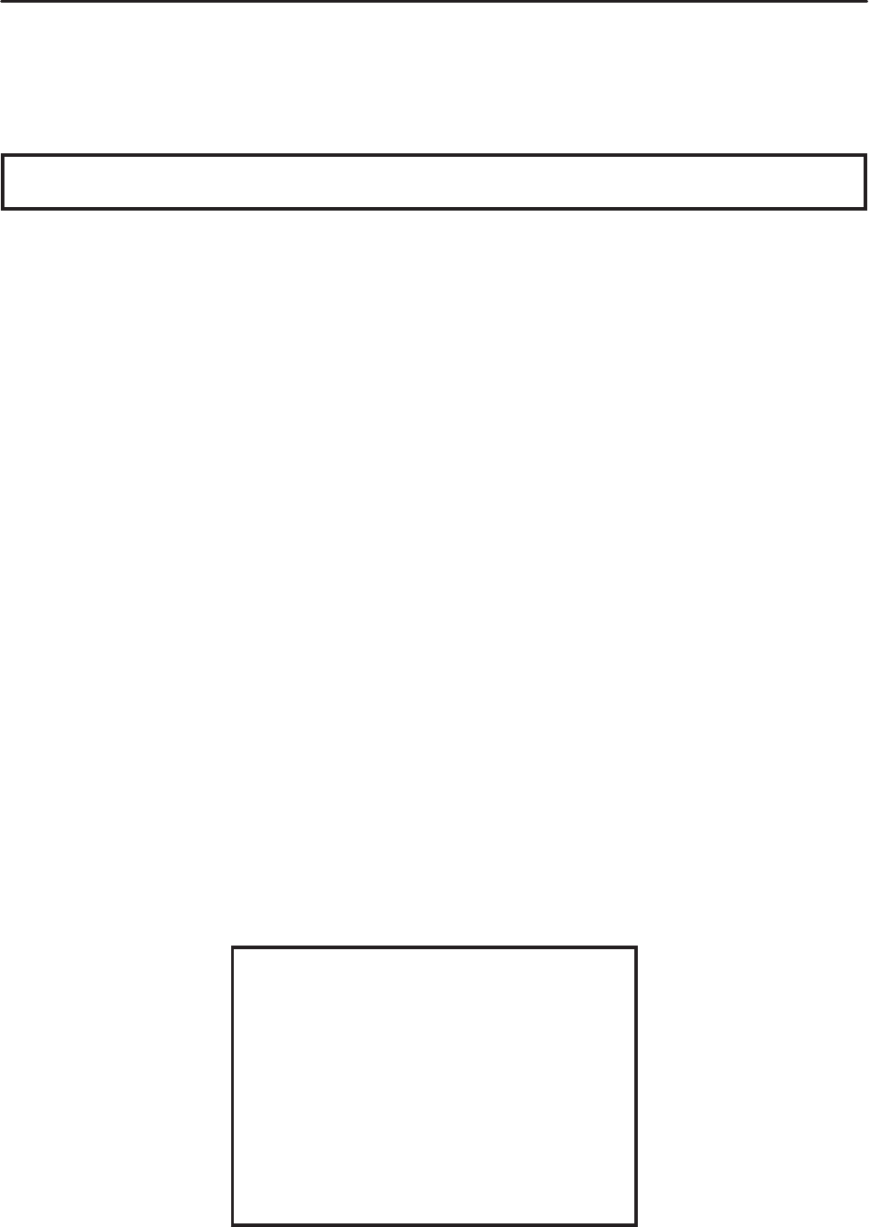
The following symbols are not relevant to every
vehicle.
Symbols 1 to 9 indicate the subject of each
chapter.
1General information
2Specifications
3Periodic checks and adjustments
4Chassis
5Engine
6Cooling system
7Fuel injection system
8Electrical system
9Troubleshooting
Symbols 10 to 17 indicate the following.
10 Serviceable with engine mounted
11 Filling fluid
12 Lubricant
13 Special tool
14 Tightening torque
15 Wear limit, clearance
16 Engine speed
17 Electrical data
Symbols 18 to 23 in the exploded diagrams indi-
cate the types of lubricants and lubrication
points.
18 Engine oil
19 Gear oil
20 Molybdenum-disulfide oil
21 Wheel-bearing grease
22 Lithium-soap- based grease
23 Molybdenum-disulfide grease
Symbols 24 to 25 in the exploded diagrams indi-
cate the following.
24 Apply locking agent (LOCTITE)
25 Replace the part

CONTENTS
SPECIFICATIONS
GENERAL SPECIFICATIONS 1. . . . . . . . . . . . . . . . . . . . . . . . . . . . . . . . . . .
ENGINE SPECIFICATIONS 1. . . . . . . . . . . . . . . . . . . . . . . . . . . . . . . . . . . . .
CHASSIS SPECIFICATIONS 1. . . . . . . . . . . . . . . . . . . . . . . . . . . . . . . . . . . .
ELECTRICAL
CHECKING THE SWITCHES 2. . . . . . . . . . . . . . . . . . . . . . . . . . . . . . . . . . . .
ELECTRIC STARTING SYSTEM 3. . . . . . . . . . . . . . . . . . . . . . . . . . . . . . . . .
CIRCUIT DIAGRAM 3. . . . . . . . . . . . . . . . . . . . . . . . . . . . . . . . . . . . . . . . .
STARTING CIRCUIT CUT-OFF SYSTEM OPERATION 5. . . . . . . . . .
TROUBLESHOOTING 6. . . . . . . . . . . . . . . . . . . . . . . . . . . . . . . . . . . . . . .
LIGHTING SYSTEM 10. . . . . . . . . . . . . . . . . . . . . . . . . . . . . . . . . . . . . . . . . . . .
CIRCUIT DIAGRAM 10. . . . . . . . . . . . . . . . . . . . . . . . . . . . . . . . . . . . . . . . .
TROUBLESHOOTING 12. . . . . . . . . . . . . . . . . . . . . . . . . . . . . . . . . . . . . . .
TROUBLESHOOTING
FAULTY LIGHTING SYSTEM 14. . . . . . . . . . . . . . . . . . . . . . . . . . . . . . . . . . . .
HEADLIGHT DOES NOT COME ON 14. . . . . . . . . . . . . . . . . . . . . . . . . .
HEADLIGHT BULB BURNT OUT 14. . . . . . . . . . . . . . . . . . . . . . . . . . . . .
TDM900 (R) 2003 WIRING DIAGRAM (EUR)
TDM900 (R) 2003 WIRING DIAGRAM (OCE)

–1–
GENERAL SPECIFICATIONS/ENGINE SPECIFICATIONS/
CHASSIS SPECIFICATIONS SPEC
SPECIFICATIONS
GENERAL SPECIFICATIONS
Item Standard Limit
Model code 5PS4 (EUR)
5PS5 (OCE)
SSS
SSS
ENGINE SPECIFICATIONS
Item Standard Limit
Throttle bodies
Model (manufacturer) quantity
Intake vacuum pressure
Throttle cable free play (at the flange
of the throttle grip)
ID mark
Throttle valve size
38EIS (MIKUNI) 2
33 X 36 kPa
3 X 5 mm
5PS1 10
#50
SSS
SSS
SSS
SSS
SSS
CHASSIS SPECIFICATIONS
Item Standard Limit
Front tire
Tire type
Size
Model (manufacturer)
Tire pressure (cold)
0 X 90 kg
90 X 203 kg
High-speed riding
Min. tire tread depth
Tubeless
120/70ZR 18 M/C (59W)
MEZ4 FRONT (METZELER)/
D220FSTJ (DUNLOP)
225 kPa (2.25 kgf/cm2, 2.25 bar)
225 kPa (2.25 kgf/cm2, 2.25 bar)
225 kPa (2.25 kgf/cm2, 2.25 bar)
SSS
SSS
SSS
SSS
SSS
SSS
SSS
1.6 mm
Rear tire
Tire type
Size
Model (manufacturer)
Tire pressure (cold)
0 X 90 kg
90 X 203 kg
High-speed riding
Min. tire tread depth
Tubeless
160/60ZR 17 M/C (69W)
MEZ4 (METZELER)/
D220STJ (DUNLOP)
250 kPa (2.5 kgf/cm2, 2.5 bar)
290 kPa (2.9 kgf/cm2, 2.9 bar)
250 kPa (2.5 kgf/cm2, 2.5 bar)
SSS
SSS
SSS
SSS
SSS
SSS
SSS
1.6 mm
–2–
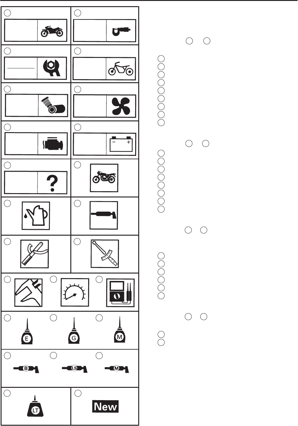
1Main switch
2Horn switch
3Pass switch
4Dimmer switch
5Hazard switch
6Turn signal switch
7Clutch switch
8Engine stop switch
9Start switch
10 Front brake light switch
11 Neutral switch
12 Rear brake light switch
13 Fuses
14 Sidestand switch
CHECKING THE SWITCHES ELEC
EAS00731
ELECTRICAL
CHECKING THE SWITCHES
Check each switch for damage or wear, proper connections, and also for continuity between the termi-
nals. Refer to “CHECKING SWITCH CONTINUITY”.
Damage/wear ! Repair or replace.
Improperly connected ! Properly connect.
Incorrect continuity reading ! Replace the switch.
–3–
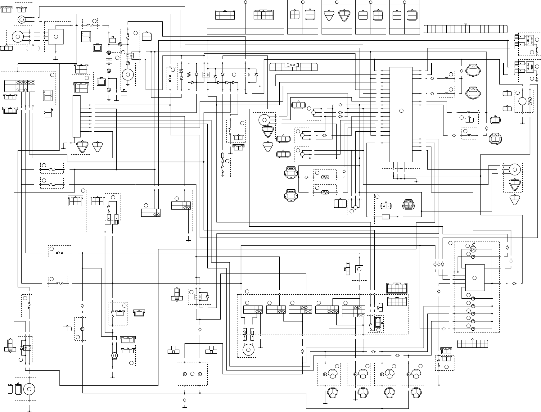
ELECTRIC STARTING SYSTEM ELEC
EAS00755
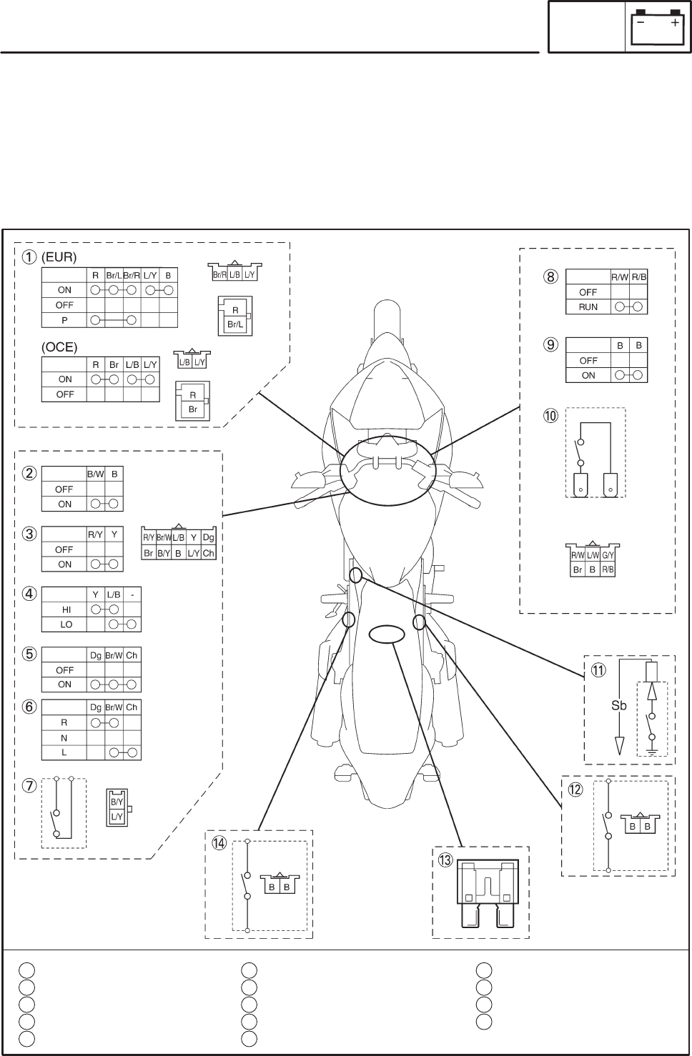
ELECTRIC STARTING SYSTEM
CIRCUIT DIAGRAM

–4–
ELECTRIC STARTING SYSTEM ELEC
4Main fuse
5Battery
7Starter relay
8Starter motor
9Main switch
12 Starting circuit cut-off relay
13 Sidestand switch
14 Neutral switch
49 Clutch switch
59 Engine stop switch
60 Start switch
61 Ignition fuse
–5–
ELECTRIC STARTING SYSTEM ELEC
EAS00756
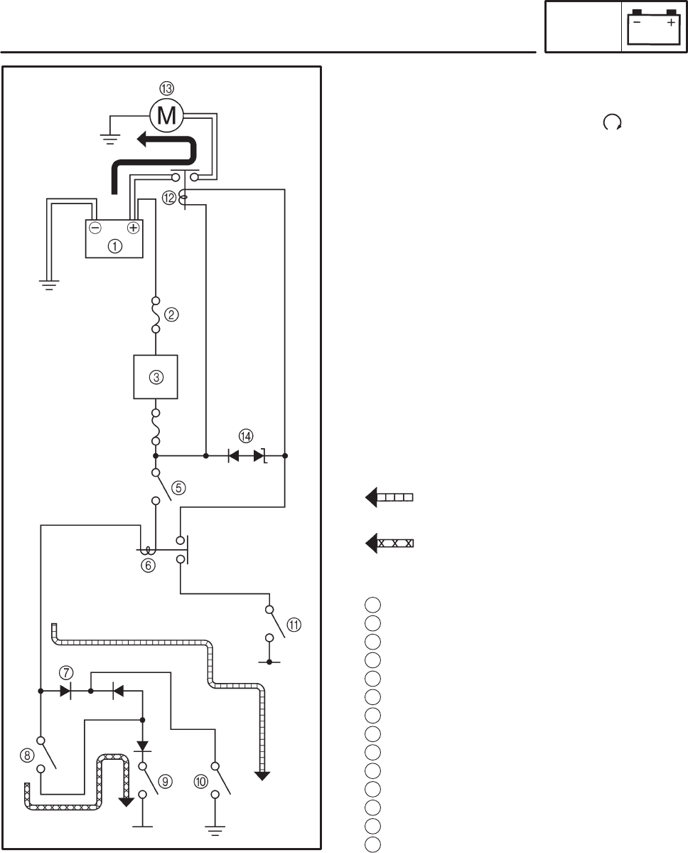
STARTING CIRCUIT CUT-OFF SYSTEM
OPERATION
If the engine stop switch is set to “ ” and the
main switch is set to “ON” (both switches are
closed), the starter motor can only operate if at
least one of the following conditions is met:
SThe transmission is in neutral (the neutral
switch is closed).
SThe clutch lever is pulled to the handlebar
(the clutch switch is closed) and the side-
stand is up (the sidestand switch is closed).
The starting circuit cut-off relay prevents the
starter motor from operating when neither of
these conditions has been met. In this instance,
the starting circuit cut-off relay is open so cur-
rent cannot reach the starter motor. When at
least one of the above conditions has been met
the starting circuit cut-off relay is closed and the
engine can be started by pressing the starter
switch.
WHEN THE TRANSMISSION IS IN
NEUTRAL
WHEN THE SIDESTAND IS UP AND
THE CLUTCH LEVER IS PULLED TO
THE HANDLEBAR
1Battery
2Main fuse
3Main switch
4Ignition fuse
5Engine stop switch
6Starting circuit cut-off relay
7Diode (starting circuit cut-off relay)
8Clutch switch
9Sidestand switch
10 Neutral switch
11 Start switch
12 Starter relay
13 Starter motor
14 Diode (starting circuit cut-off relay)
–6–
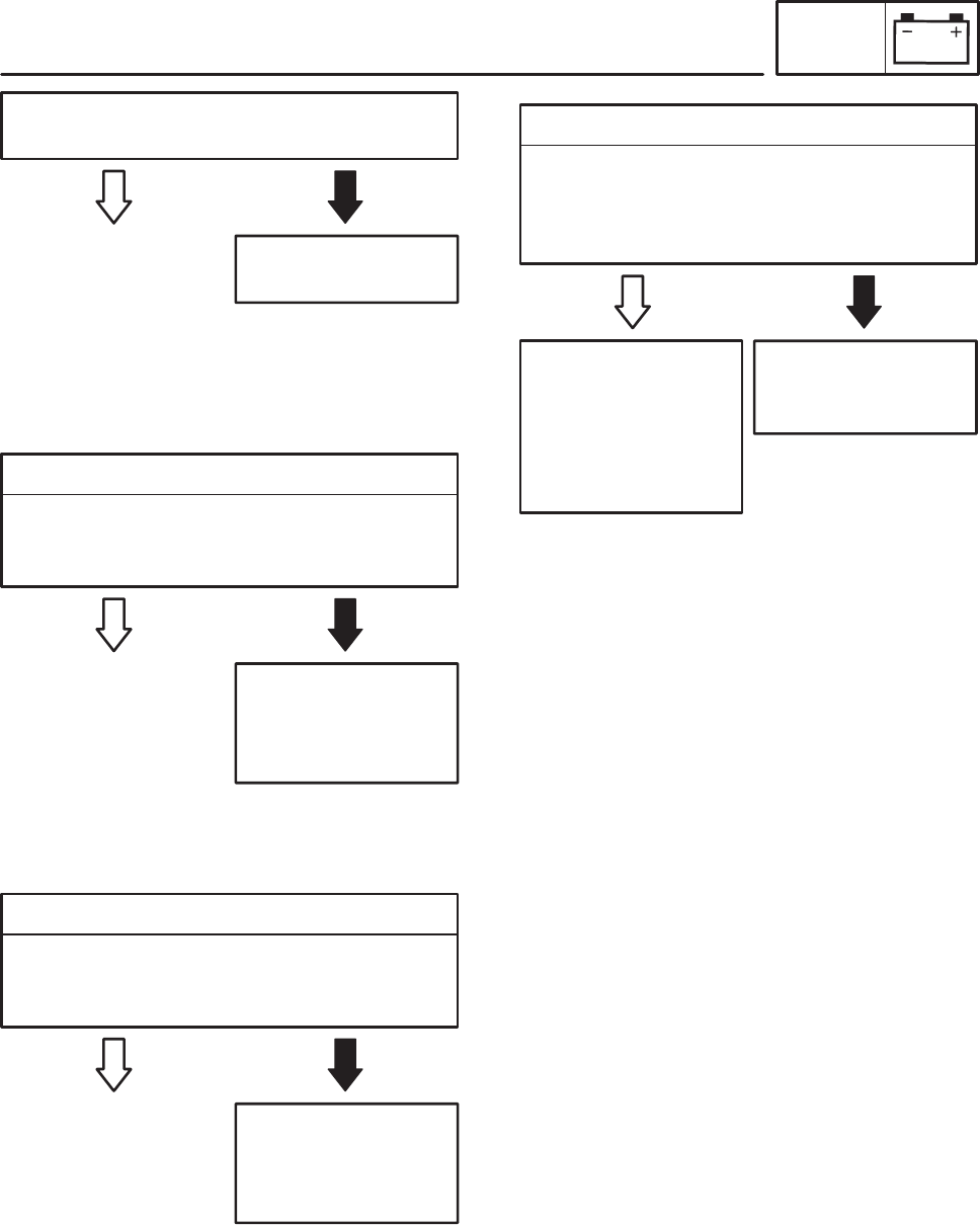
EAS00739
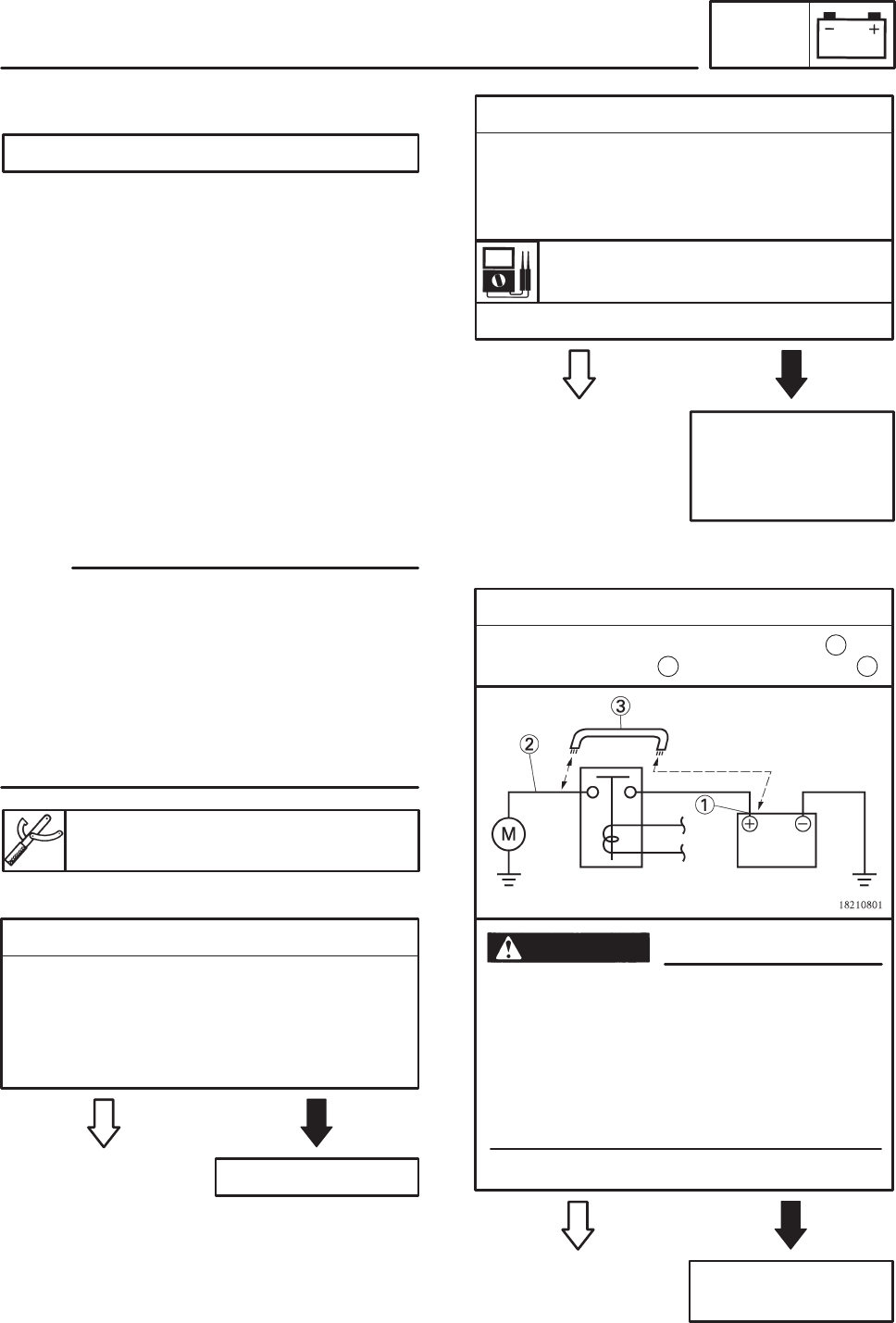
2. Battery
SCheck the condition of the battery.
Refer to “CHECKING AND CHARGING
THE BATTERY” in chapter 3. (Manual No.:
5PS1-AE1)
YES NO
SClean the battery
terminals.
SRecharge or re-
place the battery.
Minimum open-circuit voltage
12.8 V or more at 20_C
SIs the battery OK?
YES NO
3. Starter motor
SConnect the positive battery terminal and
starter motor lead with a jumper lead .
Repair or replace the
starter motor.
SA wire that is used as a jumper lead
must have at least the same capacity or
more as that of the battery lead, other-
wise the jumper lead may burn.
SThis check is likely to produce sparks,
therefore make sure nothing flammable
is in the vicinity.
SDoes the starter motor turn?
WARNING
1
2 3
EAS00758
ELECTRIC STARTING SYSTEM ELEC
The starter motor fails to turn.
NOTE:
YES NO
1. Main and ignition fuses
SCheck the main and ignition fuses for conti-
nuity.
Refer to “CHECKING THE FUSES” in chap-
ter 3. (Manual No.: 5PS1-AE1)
SAre the main and ignition fuses OK?
Replace the fuse(s).
EAS00738
EAS00757
TROUBLESHOOTING
Check:
1. main and ignition fuses
2. battery
3. starter motor
4. starting circuit cut-off relay
5. diode
6. starter relay
7. main switch
8. engine stop switch
9. neutral switch
10. sidestand switch
11. clutch switch
12. start switch
13. wiring connections
(of the entire starting system)
SBefore troubleshooting, remove the following
part(s):
1. seat
2. fuel tank
3. air filter case
4. side cowlings
STroubleshoot with the following special
tool(s).
Pocket tester
90890-03132
–7–
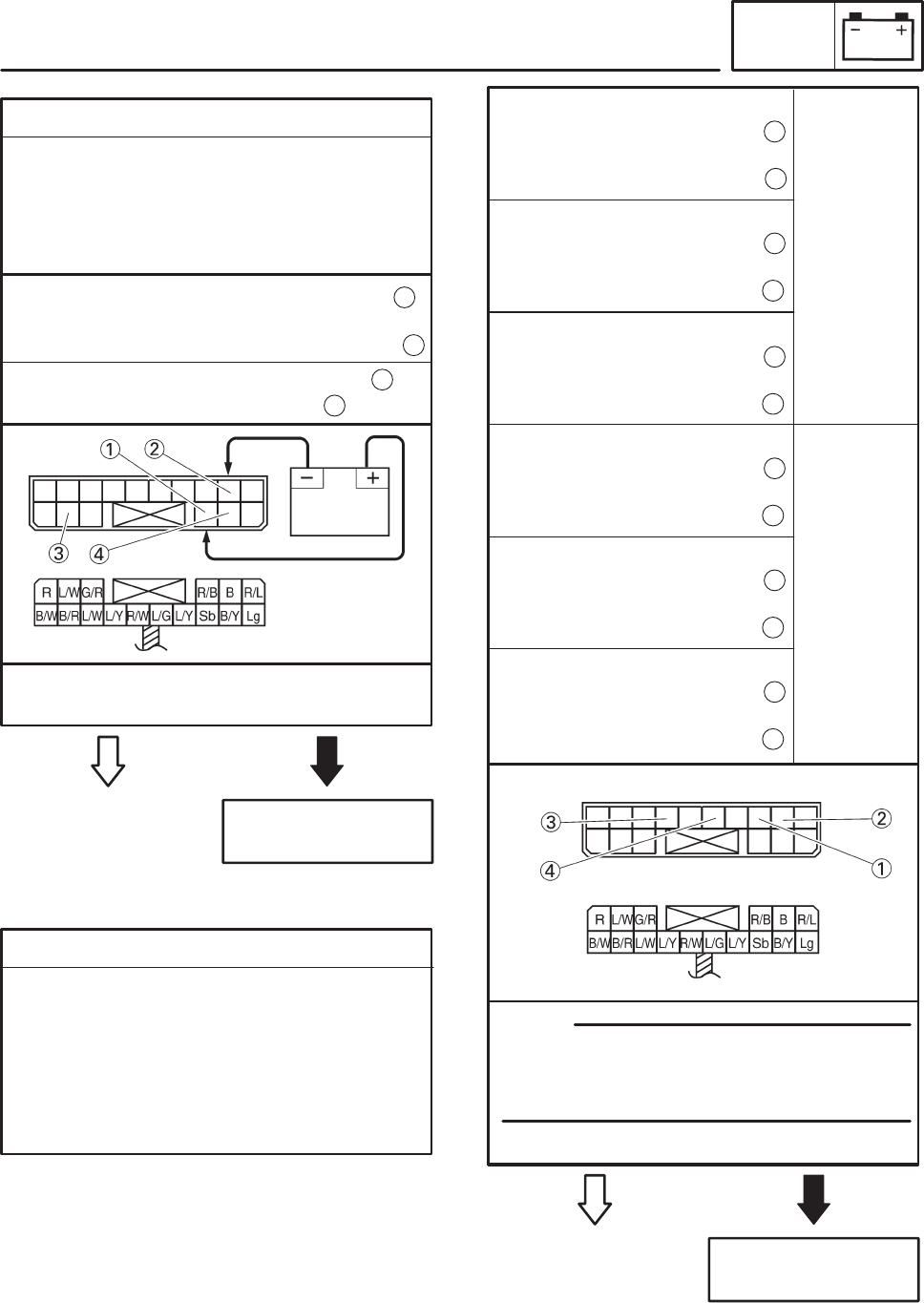
4. Starting circuit cut-off relay
SDisconnect the starting circuit cut-off relay
from the wire harness.
SConnect the pocket tester (Ω 1) and bat-
tery (12 V) to the starting circuit cut-off relay
terminals as shown.
YES NO
Replace the starting
circuit cut-off relay.
SDoes the starting circuit cut-off relay have
continuity between blue/white and black?
EAS00759
Continuity
Tester positive probe !
sky blue
Tester negative probe !
blue/yellow
No conti-
nuity
1
2
1
3
Tester positive probe !
sky blue
Tester negative probe !
black/yellow
Battery positive terminal ! red/black
Battery negative terminal !
black/yellow
1
2
Tester positive prove ! blue/white
Tester negative prove ! black
3
4
5. Starting circuit cut-off relay (diode)
SDisconnect the starting circuit cut-off relay
from the wire harness.
SConnect the pocket tester (Ω 1) to the
starting circuit cut-off relay terminals as
shown.
SMeasure the starting circuit cut-off relay for
continuity as follows.
Tester positive probe !
blue/green
Tester negative probe !
blue/yellow
4
3
Tester positive probe !
black/yellow
Tester negative probe !
sky blue
2
1
Tester positive probe !
blue/yellow
Tester negative probe !
sky blue
3
1
Tester positive probe !
blue/yellow
Tester negative probe !
blue/green
3
4
When you switch the tester’s positive and
negative probes, the readings in the above
chart will be reversed.
SAre the testing readings correct?
YES NO
Replace the starting
circuit cut-off relay.
NOTE:
EAS00760
ELECTRIC STARTING SYSTEM ELEC

–8–
6. Starter relay
SDisconnect the starter relay from the cou-
pler.
SConnect the pocket tester (Ω 1) and bat-
tery (12 V) to the starter relay terminals as
shown.
YES NO
Replace the starter
relay.
SDoes the starter relay have continuity be-
tween red and black?
EAS00761
Battery positive terminal ! red/white
Battery negative terminal !
blue/white
1
2
Tester positive probe ! red
Tester negative probe ! black
3
4
EAS00749
7. Main switch
SCheck the main switch for continuity.
Refer to “CHECKING THE SWITCHES”.
SIs the main switch OK?
YES NO
Replace the main
switch.
EAS00750
8. Engine stop switch
SCheck the engine stop switch for continuity.
Refer to “CHECKING THE SWITCHES”.
SIs the engine stop switch OK?
YES NO
Replace the right
handlebar switch.
EAS00751
9. Neutral switch
SCheck the neutral switch for continuity.
Refer to “CHECKING THE SWITCHES”.
SIs the neutral switch OK?
YES NO
Replace the neutral
switch.
EAS00752
10. Sidestand switch
SCheck the sidestand switch for continuity.
Refer to “CHECKING THE SWITCHES”.
SIs the sidestand switch OK?
YES NO
Replace the side-
stand switch.
11. Clutch switch
SCheck the clutch switch for continuity.
Refer to “CHECKING THE SWITCHES”.
SIs the clutch switch OK?
YES NO
Replace the clutch
switch.
EAS00763
ELECTRIC STARTING SYSTEM ELEC

–9–
ELECTRIC STARTING SYSTEM ELEC
12. Start switch
SCheck the start switch for continuity.
Refer to “CHECKING THE SWITCHES”.
SIs the start switch OK?
YES NO
Replace the right
handlebar switch.
EAS00764
13. Wiring
SCheck the entire starting system’s wiring.
Refer to “CIRCUIT DIAGRAM”.
SIs the starting system’s wiring properly con-
nected and without defects?
YES NO
Properly connect or
repair the starting
system’s wiring.
EAS00766
The starting system
circuit is OK.
–10–
LIGHTING SYSTEM ELEC
EAS00780
LIGHTING SYSTEM
CIRCUIT DIAGRAM
–11–
LIGHTING SYSTEM ELEC
4Main fuse
5Battery
9Main switch
23 ECU
37 High beam indicator light
40 Meter light
45 Pass switch
46 Dimmer switch
55 Headlight
56 Headlight relay
62 Headlight fuse
63 Hazard light fuse
64 Signaling system fuse
67 Tail/brake light
70 Auxiliary light

–12–
YES NO
2. Battery
SCheck the condition of the battery.
Refer to “CHECKING AND CHARGING
THE BATTERY” in chapter 3. (Manual No.:
5PS1-AE1)
SClean the battery
terminals.
SRecharge or re-
place the battery.
EAS00739
Minimum open-circuit voltage
12.8 V or more at 20_C
SIs the battery OK?
YES NO
3. Main switch
SCheck the main switch for continuity.
Refer to “CHECKING THE SWITCHES”.
SIs the main switch OK?
Replace the main
switch.
EAS00749
4. Headlight relay
SDisconnect the headlight relay from the wire
harness.
SConnect the pocket tester (Ω 1) and bat-
tery (12 V) to the headlight relay terminal as
shown.
SCheck the headlight relay for continuity.
Battery positive terminal ! red/yellow
Battery negative terminal !
yellow/black
1
2
Tester positive probe ! red/yellow
Tester negative probe ! blue/black
3
4
LIGHTING SYSTEM ELEC
NOTE:
YES NO
1. Main, signaling system and headlight
fuses
SCheck the main, signaling system and head-
light fuses for continuity.
Refer to “CHECKING THE FUSES” in chap-
ter 3. (Manual No.: 5PS1-AE1)
SAre the main, parking lighting and headlight
fuses OK?
Replace the fuse(s).
EAS00781
TROUBLESHOOTING
Any of the following fail to light: headlight,
high beam indicator light, taillight, auxilia-
ry light or meter light.
Check:
1. main, signaling system and headlight fuses
2. battery
3. main switch
4. headlight relay
5. dimmer switch
6. pass switch
7. wiring connections
(of the entire lighting system)
SBefore troubleshooting, remove the following
part(s):
1. fuel tank
2. front cowling
3. rear cowling
STroubleshoot with the following special
tool(s).
Pocket tester
90890-03132
EAS00738
–13–
LIGHTING SYSTEM ELEC
EAS00784
YES NO
5. Dimmer switch
SCheck the dimmer switch for continuity.
Refer to “CHECKING THE SWITCHES”.
SIs the dimmer switch OK?
The dimmer switch is
faulty. Replace the
left handlebar
switch.
EAS00786
YES NO
6. Pass switch
SCheck the pass switch for continuity.
Refer to “CHECKING THE SWITCHES”.
SIs the pass switch OK?
The pass switch is
faulty. Replace the
left handlebar
switch.
EAS00787
YES NO
7. Wiring
SCheck the entire lighting system’s wiring.
Refer to “CIRCUIT DIAGRAM”.
SIs the lighting system’s wiring properly con-
nected and without defects?
Properly connect or
repair the lighting
system’s wiring.
Check the condition
of each of the lighting
system’s circuits.
Refer to “CHECK-
ING THE LIGHTING
SYSTEM”.
YES NO
SDose the headlight relay have continuity be-
tween red/yellow and green/blue?
Replace the head-
light relay.

–14–
FAULTY LIGHTING SYSTEM TRBL
SHTG
EAS00866
TROUBLESHOOTING
FAULTY LIGHTING SYSTEM
HEADLIGHT DOES NOT COME ON
SWrong headlight bulb
SToo many electrical accessories
SHard charging
SIncorrect connection
SImproperly grounded circuit
SPoor contacts (main or dimmer switch)
SHeadlight relay
SBurnt-out headlight bulb
HEADLIGHT BULB BURNT OUT
SWrong headlight bulb
SFaulty battery
SFaulty rectifier/regulator
SImproperly grounded circuit
SFaulty main switch
SFaulty dimmer switch
SFaulty headlight relay
SHeadlight bulb life expired

62 Headlight fuse
63 Hazard fuse
64 Signaling system fuse
65 Radiator fan motor fuse
66 Rear brake light switch
67 Tail/brake light
68 Radiator fan relay
69 Radiator fan motor
70 Auxiliary light
COLOR CODE
B Black. . . . . . .
Br Brown. . . . . .
Ch Chocolate. . . . .
Dg Dark green. . . . .
G Green. . . . . .
Gy Gray. . . . .
L Blue. . . . . . .
Lg Light green. . . . . .
O Orange. . . . . .
P Pink. . . . . . .
R Red. . . . . . .
Sb Sky blue. . . . . .
W White. . . . . .
Y Yellow. . . . . . .
B/L Black/Blue. . . . .
B/W Black/White. . . .
B/Y Black/Yellow. . . .
Br/B Brown/Black. . . .
Br/G Brown/Green. . .
Br/L Brown/Blue. . . .
Br/R Brown/Red. . . .
Br/W Brown/White. . .
G/B Green/Black. . . .
G/R Green/Red. . . .
G/W Green/White. . . .
G/Y Green/Yellow. . . .
Gy/G Gray/Green. . .
Gy/R Gray/Red. . .
L/B Blue/Black. . . . .
L/G Blue/Green. . . .
L/R Blue/Red. . . .
L/W Blue/White. . . .
L/Y Blue/Yellow. . . . .
P/W Pink/White. . . .
R/B Red/Black. . . .
R/G Red/Green. . . .
R/L Red/Blue. . . .
R/W Red/White. . . .
R/Y Red/Yellow. . . .
W/B White/Black. . . .
W/Y White/Yellow. . . .
Y/B Yellow/Black. . . .
Y/G Yellow/Green. . . .
Y/L Yellow/Blue. . . . .
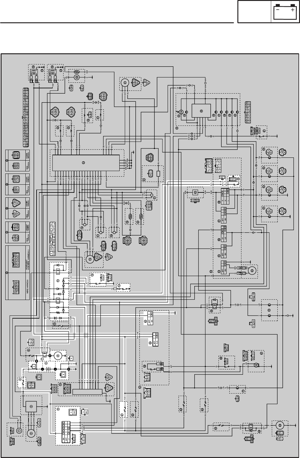
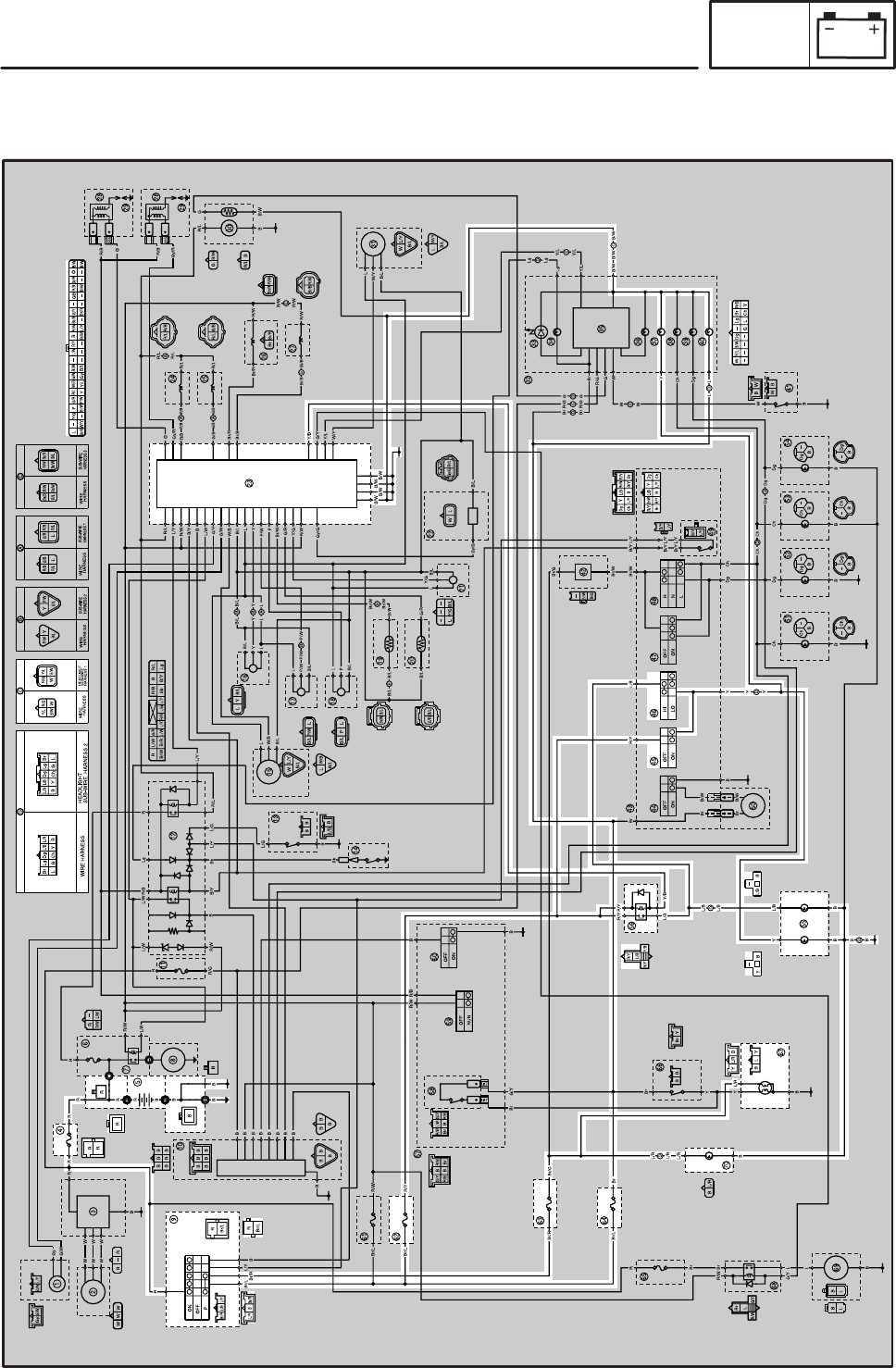
1Crankshaft position sensor
2A.C magneto
3Rectifier/regulator
4Main fuse
5Battery
6Fuel injection system fuse
7Starter relay
8Starter motor
9Main switch
10 Alarm
11 Buck up fuse
12 Starting circuit cut-off relay
13 Sidestand switch
14 Neutral switch
15 Cylinder identification sensor
16 Throttle position sensor
17 Intake air pressure sensor
18 Atmospheric pressure sensor
19 Intake air temperature sensor
20 Coolant temperature sensor
21 Lean angle cut-off relay
22 O2 sensor
23 ECU
24 Injector (#1)
25 Injector (#2)
26 Al system solenoid
27 Intake solenoid
28 Ignition coil
29 Spark plug
30 Fuel pump
31 Speed sensor
32 Meter assembly
33 Oil level warning light
34 Neutral indicator light
35 Multi-function meter
36 Engine trouble warning light
37 Hi beam indicator light
38 Left turn signal indicator light
39 Right turn signal indicator light
40 Meter light
41 Oil level switch
42 Turn signal relay
43 Left handlebar switch
44 Horn switch
45 Pass switch
46 Dimmer switch
47 Hazard switch
48 Turn signal switch
49 Clutch switch
50 Horn
51 Rear turn signal light (left)
52 Rear turn signal light (right)
53 Front turn signal light (left)
54 Front turn signal light (right)
55 Headlight
56 Headlight relay
57 Right handlebar switch
58 Front brake light switch
59 Engine stop switch
60 Start switch
61 Ignition fuse
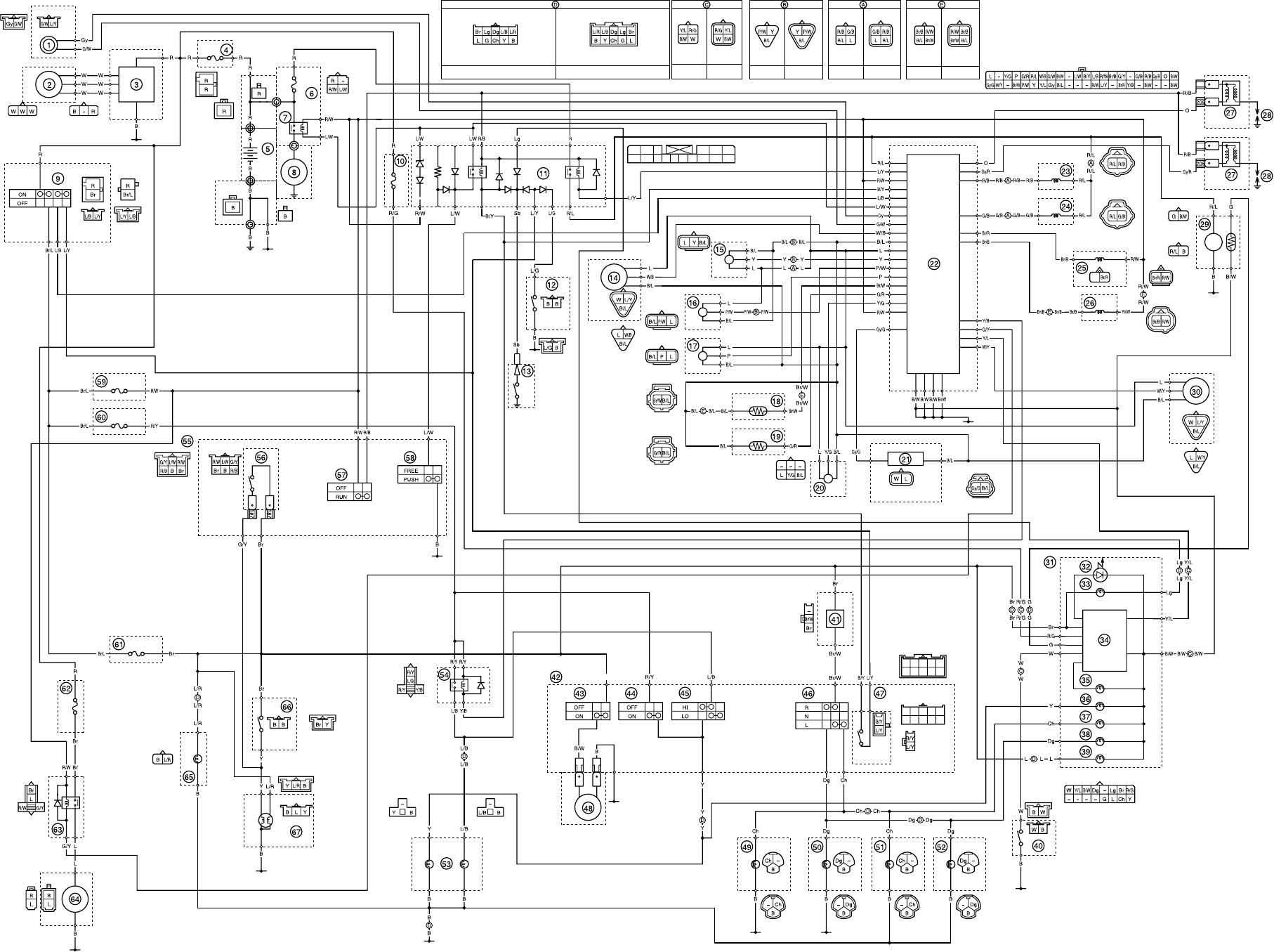
WIRING DIAGRAM (EUR)

62 Radiator fan motor fuse
63 Radiator fan relay
64 Radiator fan motor
65 Auxiliary light
66 Rear brake light switch
67 Tail/brake light
COLOR CODE
B Black. . . . . . .
Br Brown. . . . . .
Ch Chocolate. . . . .
Dg Dark green. . . . .
G Green. . . . . .
Gy Gray. . . . .
L Blue. . . . . . .
Lg Light green. . . . . .
O Orange. . . . . .
P Pink. . . . . . .
R Red. . . . . . .
Sb Sky blue. . . . . .
W White. . . . . .
Y Yellow. . . . . . .
B/L Black/Blue. . . . .
B/W Black/White. . . .
B/Y Black/Yellow. . . .
Br/B Brown/Black. . . .
Br/L Brown/Blue. . . .
Br/R Brown/Red. . . .
Br/W Brown/White. . .
G/B Green/Black. . . .
G/R Green/Red. . . .
G/W Green/White. . . .
G/Y Green/Yellow. . . .
Gy/G Gray/Green. . .
Gy/R Gray/Red. . .
L/B Blue/Black. . . . .
L/G Blue/Green. . . .
L/R Blue/Red. . . .
L/W Blue/White. . . .
L/Y Blue/Yellow. . . . .
P/W Pink/White. . . .
R/B Red/Black. . . .
R/G Red/Green. . . .
R/L Red/Blue. . . .
R/W Red/White. . . .
R/Y Red/Yellow. . . .
W/Y White/Yellow. . . .
Y/B Yellow/Black. . . .
Y/G Yellow/Green. . . .
Y/L Yellow/Blue. . . . .
1Crankshaft position sensor
2A.C magneto
3Rectifier/regulator
4Main fuse
5Battery
6Fuel injection system fuse
7Starter relay
8Starter motor
9Main switch
10 Buck up fuse
11 Starting circuit cut-off relay
12 Sidestand switch
13 Neutral switch
14 Cylinder identification sensor
15 Throttle position sensor
16 Intake air pressure sensor
17 Atmospheric pressure sensor
18 Intake air temperature sensor
19 Coolant temperature sensor
20 Lean angle cut-off switch
21 O2 sensor
22 ECU
23 Injector (#1)
24 Injector (#2)
25 Al system solenoid
26 Intake solenoid
27 Ignition coil
28 Spark plug
29 Fuel pump
30 Speed sensor
31 Meter assembly
32 Oil level warning light
33 Neutral indicator light
34 Multi function meter
35 Engine trouble warning light
36 Hi beam indicator light
37 Left turn signal indicator light
38 Right turn signal indicator light
39 Meter light
40 Oil level switch
41 Turn signal relay
42 Left handlebar switch
43 Horn switch
44 Pass switch
45 Dimmer switch
46 Turn signal switch
47 Clutch switch
48 Horn
49 Rear turn signal light (left)
50 Rear turn signal light (right)
51 Front turn signal light (left)
52 Front turn signal light (right)
53 Headlight
54 Headlight relay
55 Right handlebar switch
56 Front brake light switch
57 Engine stop switch
58 Start switch
59 Ignition fuse
60 Headlight fuse
61 Signaling system fuse
WIRING DIAGRAM (OCE)

RB
DgLgBr
BYChGL
ON
OFF
P
R
L/Y
OFF
ON
OFF
ON
HI
LO
OFF
ON
R
N
L
YLB
YB
BBB
BBB
BB
B
B/Y
L/Y
OFF
RUN
OFF
ON
B
L
Gy
G/W G/W
L/Y
L/WR/W
L/B L/R
Dg Lg Br
BYChGL
L/BL/R Y/L
B/W
R/G
L/BBr/R
B
R/W G/Y
Br/R
L/Y
WWW
W
Gy
G/W
R/W
R/G
L/G L
W/B
B/L
B/L
Y
L
L
L
Gy/G
B/L
B/L
Y/G
P
B/L
L
B/L
B
R/L
L/Y
R/W
B/Y
B
L/W
G/Y
G/W
W/B
B/L Br/B
R/L
R/L
G/Y
Y/L
B/L
W/Y
W/Y
L
Br/R
G/B
R/B
Gy/R
O
L
Y
P/W
B/W B/W
B/W B/W
P
Br/W
G/R
Y/G
R/W
Gy/G
BB/Y
RLgR/BL/W
Sb L/Y
L/Y
L/G R/L
R
L/W
W
W
B
Br/L L/Y
Br/R B
R/W
R/Y
R/W R/B B
Sb
BBr
Br/L
Br/L
R
R
Br
Br
L
B
B
Y
B B
L/B
L/R
L/RY
Br
Y
L
B
R/W
G/Y
R R R
R
R
R
R
B
B
B
B
B
BB
W
W
W
B
L
R
Br/L
Br/L
L/G
B
BB
Br/R
Br
Br/R
R/W
BR/L
B/W
G
205
205
BBB
BBB
BB
B
R L/W R/LR/B B
G/R
B/RB/W
L/W R/WL/Y L/YL/G
Sb B/Y Lg
WL/Y
B/L
W/YL
B/L
B/L
Y/G
L
WL/Y
B/L
Br
L
R/Y Y/B
R/Y
L/B
B/L
G/R
W/B
L
B/L
B/L P L
B/W
B/WB/WR/W
O
Gy/R
R/B
G/B
G/YBr/B
Br/R
R/W
B
B/YL/WB/W
G/W
W/BR/L
G/R
P
Y/G
L
L/Y
B/L
Gy
Y/L
Y
P/W
Br/W
W/Y
Gy/G
W
Y/L P/W P/W R/B
R/L
G/B
B/L B/L
B/W
R/G
WL
R/B
R/L
G/B
L
YY
R
R
B
B
RR
R
BW
BW
WIRE HARNESS HEADLIGHT
SUB-WIRE HARNESS 2
WIRE
HARNESS WIRE
HARNESS WIRE
HARNESS WIRE
HARNESS
HEADLIGHT
SUB-WIRE
HARNESS 1
L Y B/L
YB
--
B
L/R
L/R
G/Y G/Y
R/W R/W L/W
B
R/B R/B
Br Br
BB
L/B
B
R/G
BrLgDg
B/W
Y/L
W
YChLG
B/L
P/W
L
B
R/W
Br/B
B/L
Br/W
R/L
R/B
R/L
G/B
Br Y
BB
187
187
Ch
B
Ch
B
1
2 3
4
6
5
7
8
R/W
L/W
11
12
910
61
62
58
59
60
57
14
13 15
16
17
18
19
23
24
25
21
22
31
27
30
29
29
28
28
26
20
Br/G
Br/R
63
Br
Br/L
64
65
68
70
67
55
56
44
43
50
45 46 47 48
42
49
51
66
69
-
-
-
--
- --- -
Y/B
--
---
-
-
-
L/R
L/R
D
Br/W
E
B
B
Ch
Ch
B/Y
B/Y
L/Y
L/Y
Dg
B
Dg
B
52
-
-
-
Br/W
Br/G
B
Dg
Dg
Dg
B
Dg
B
54 41
40
39
38
37
36
34
35
32 33
-
----
-
-
B
B
W
Dg
Ch
B
Ch
B
53
-
-
B
Ch
B
D
L/B
L/B
D
Y
YB
Y
R/YBr L/B Br/W
Br/W
Br/G
B/Y L/Y
Br
D
W
W
C
G
G
DY/L
Y/L
C
Lg
Lg
D
Br
Br
D
R/G
R/G
C
Dg Dg
D
LLL
Dg
Ch
Y
Br
R/G
G
W
Y/L
Lg
D
B/WB/W B/W
C
Ch Ch
D
P/WP/W P/W
B
B/L B/L
B
B/L B/L
B/L G/R
Br/W
E
Y Y
B
L L
A
G/B G/B
A
R/B R/B
A
Br/B Br/B
E
D C B
SUB-WIRE
HARNESS 2
SUB-WIRE
HARNESS 1
SUB-WIRE
HARNESS 3
A
Br/B
B/L Br/W
R/W Br/B
B/LBr/W
R/W
E
Br/W
R/L
A
R/L
R/W
B
R/L
Gy/R
R/B
R/B
O
G
B/W
R/W
E
R/W
Br/R R/W
B/W
B
B
B
B
B
B
Y/B
R/YR/Y
Y/BL/B
B/Y
L/Y
R/Y L/B
Ch
B/YBr L/Y
Br/W
YDg
B
R/YL/B
Ch B/Y Br
L/Y
Br/W
YDg
B
Br
G/Y
G/Y
TDM900 (R) 2003 WIRING DIAGRAM (EUR)
R L/W R/LR/B L/W
G/R
B/RB/W
L/W R/WL/Y L/YL/G
Sb B/Y Lg
R/Y L/B
Ch
B/YBr L/Y
Br/W
YDg
B
R/YL/B
Ch B/Y Br
L/Y
Br/W
YDg
B
WIRE HARNESS HEADLIGHT
SUB-WIRE HARNESS 2
WIRE
HARNESS WIRE
HARNESS WIRE
HARNESS WIRE
HARNESS
HEADLIGHT
SUB-WIRE
HARNESS 1
SUB-WIRE
HARNESS 2 SUB-WIRE
HARNESS 1
SUB-WIRE
HARNESS 3
Br
Br
TDM900 (R) 2003 WIRING DIAGRAM (OCE)
