Aclara Technologies 9975T Aclara Synergize RF Network DCU XCVR User Manual 101 9975T SRFN
Aclara Technologies LLC Aclara Synergize RF Network DCU XCVR 101 9975T SRFN
Contents
- 1. Users Manual
- 2. Label Instruction
- 3. User Manual
Users Manual

www.Aclara.com
101-9975T-SRFN
User Manual
DRAFT
DRAFT

101-9975T-SRFN User Manual
Proprietary Notice
Information contained in this document is private to Aclara Technologies LLC an Ohio limited
liability company (Aclara). This information may not be published, reproduced, or otherwise
disseminated without the express written authorization of Aclara.
Any software or firmware described in this document is furnished under a license and may be
used or copied only in accordance with the terms of such license.
Disclaimer
The information in this document is subject to change without notice and should not be construed
as a commitment by Aclara. Aclara assumes no responsibility for any errors that may appear in
this document.
No responsibility is assumed for the use or reliability of software on equipment that is not
supplied by Aclara.
TWACS, STAR, and Metrum Cellular are registered trademarks of Aclara Technologies LLC.
Aclara Technologies LLC
Confidential and Proprietary
Copyright 2015. All Rights Reserved.
DRAFT
DRAFT
MTU Installation Guidelines iii
W
ARNINGS
, C
AUTIONS
,
AND
N
OTES
Always consult and adhere to all local and national safety codes, regulations, and
standards.WARNING, CAUTION and Note statements are used throughout this
manual to emphasize important and critical information to help you ensure safety
and prevent product damage. These statements are defined below.
W
ARNING
Indicates a potentially hazardous situation which, if not avoided, could result
in death or serious physical injury.
C
AUTION
Indicates a situation, which, if not avoided, could result in damage to
equipment, damage to software, loss of data or invalid results.
N
OTE
Indicates important supplemental information.
DRAFT

iv MTU Installation Guidelines
FCC/IC Compliance
FCC/IC Compliance
The following statements cover the RF exposure guide and the field calibration
procedure.
FCC/IC RF Exposure Guide
Aclara Technologies LLC low power RF devices and their antennas must be
fixed-mounted on indoor or outdoor permanent structure(s) providing a separation
distance of at least 20 cm from all persons during normal operation. This device is
not designed (and it has no external connection) to operate in conjunction with any
other antennas or transmitters. No other operating instructions for satisfying RF
exposure compliance are needed.
Field Calibration Procedure
Aclara Technologies LLC low power RF devices have passed through extensive
and multitask testing and calibration procedures while in the factory. Therefore, no
additional calibration or adjustment is required in the field. Aclara Technologies
LLC low power RF devices are shipped to the customer in the sealed enclosures.
Thus, no adjustments can be made in the field, without breaking the factory sealed
enclosure.
Antenna
This radio transmitter (4546A-9975T) has been approved by Industry Canada to
operate with the antenna types listed below with the maximum permissible gain
indicated. Antenna types not included in this list, having a gain greater than the
maximum gain indicated for that type, are strictly prohibited for use with this
device.
Manufacturer Manufacturer Part Number dBi
Laird Technologies FG4605 5
MAXRAD MFB4605(NF) 5
DRAFT

Avertissements, mises en garde et remarques
MTU Installation Guidelines v
A
VERTISSEMENTS
,
MISES
EN
GARDE
ET
REMARQUES
Toujours consulter et respecter les codes, règlements et normes de sécurité locaux
et nationaux. Des AVERTISSEMENTS, MISES EN GARDE et remarques sont
utilisés tout au long de ce guide pour souligner l'information importante et critique
qui vous aidera à assurer la sécurité et à prévenir les dommages au produit. Ces
énoncés sont définis ci-dessous.
A
VERTISSEMENT
indique une situation potentiellement dangereuse qui, si elle n'était pas évitée,
pourrait entraîner la mort ou des blessures graves.
M
ISE
E
N
G
ARDE
indique une situation qui, si elle n'était pas évitée, pourrait entraîner des
dommages à l'équipement, des dommages au logiciel, des pertes de données ou
des résultats invalides.
R
EMARQUE
indique des informations supplémentaires importantes.
DRAFT

vi MTU Installation Guidelines
Conformité FCC/IC
Conformité FCC/IC
Les énoncés qui suivent portent sur le guide d'exposition aux RF et la procédure de
calibration sur place.
Guide d'exposition aux RF FCC/IC
Les appareils RF à faible puissance Aclara Technologies LLC ainsi que leurs
antennes doivent être montés de manière fixe sur des structures intérieures ou
extérieures permanentes qui se trouvent à au moins 20 cm des personnes pendant
le fonctionnement normal. Cet appareil n'est pas conçu (et il n'a aucun
branchement externe) pour être utilisé en association avec toute autre antenne ou
tout transmetteur. Aucune autre instruction d'utilisation n'est requise pour assurer
la conformité aux règles d'exposition aux RF.
Procédure de calibration sur place
Les appareils RF à faible puissance Aclara Technologies LLC ont été soumis à des
tests étendus et multi-tâches et à des procédures de calibration complexes en usine.
Par conséquent, ils ne requièrent pas de calibration ni d'ajustement supplémentaire
sur place. Les appareils RF à faible puissance Aclara Technologies LLC sont
expédiés au client dans des boîtiers scellés. Aucun ajustement ne peut donc être
effectué sur place sans briser le boîtier scellé en usine.
Antenne
Cet émetteur radio (4546A-9975T) a été approuvé par Industrie Canada pour
fonctionner avec l'antenne types énumérés ci-dessous avec le maximum de gain
admissible indiqué. Types d'antenne non inclus dans cette liste, ayant un gain
supérieur au gain maximum indiqué pour ce type, sont strictement interdits pour
une utilisation avec cet appareil.
Référence du fabricant Numéro de pièce fabricant dBi
Laird Technologies FG4605 5
MAXRAD MFB4605(NF) 5
DRAFT
101-9975T-SRFN User Manual 1
9975T F
INAL
T
EST
I
NSTRUCTION
Writtenby: DavidGeorge
Title: TestEngineer
Revision History
Purpose
The purpose of this document is to provide instructions for testing of the 9975T
transciever board during Final DCU Test and Integration.
Scope
The scope of this instruction includes the testing of functionality of the transmit
and all 8 receive channels, as well as configuring customer settings.
Related Documents
SRFNI-XCVR Configuration Workflow
477-2015-001-TRS
Revision Description Revisedby Date
AInitialRelease DGeorge 2015‐11‐12
B AddedfirmwarechecksDGeorge 2015‐11‐12
DRAFT
2101-9975T-SRFN User Manual
Test Instruction
Test Instruction
CAUTION:
Make sure antenna cable is plugged into the DCU! This test transmits to an end
point and transmitting without a load can damage the transmitter!
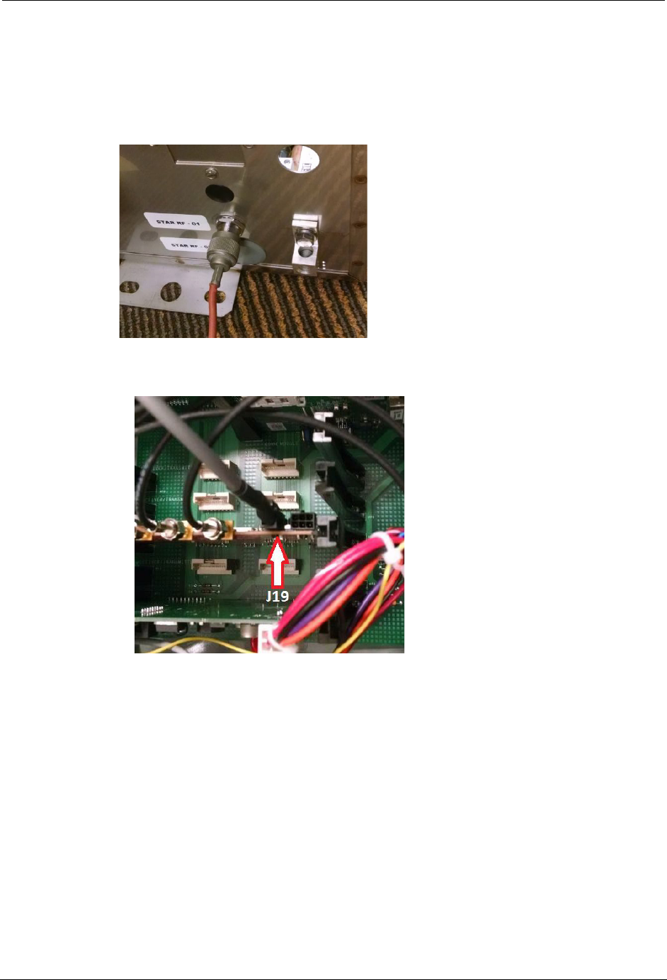
1. Plug the communications cable into the 4-pin connector J19 of 9975T board.
2. Make sure DCU under test has been powered for at least 2 minutes to allow
9975T time to boot up.
3. On DCU Main board verify:
•CPU Board has 02.40.0009 Firmware or higher
•9975T board is recognized with a “w” response and reports a firmware
version of 1.10.0033
•Make a note of the current number of test records
DRAFT
Test Instruction
101-9975T-SRFN User Manual 3
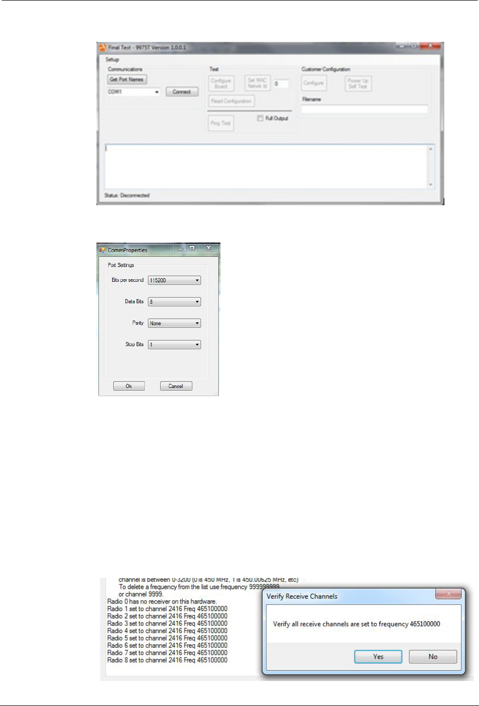
4. Launch the Final Test – 9975T application.
5. Select Setup, and set the correct Comm Properties.
6. Click the Get Port Names button.
7. Select the correct COM Port Name for the cable that is plugged into the 9975T
board.
8. Click the Connect button.
9. Select Read Configuration, and verify communications response from the
9975T.
10. Select Set MAC Network ID and set MAC Network ID to 0.
11. Click the Configure Board button.
12. Verify all receive channels are set to the correct frequency.
DRAFT

4101-9975T-SRFN User Manual
Test Instruction
13. Verify Transmit Channel frequency.
14. If all frequencies are set correctly, select Ping Test.
15. Verify Radios 1 – 8 have received a ping response from the factory end point
with a signal strength no less negative than -30 dBm
DRAFT

Customer Configuration Instruction
101-9975T-SRFN User Manual 5
Customer Configuration Instruction
1. Verify communications with 9975T by clicking Read Configuration, if
necessary
2. Click the Configure button.
3. Select the appropriate customer .xml file.
4. Click the Open button. The program will now configure the 9975T with
customer frequencies and settings.
5. Select Read Configuration, and verify that the frequency settings are correct
per customer work order (move the scroll bar of the output window up to
display Receive and Transmit Frequencies).
DRAFT
6101-9975T-SRFN User Manual
Customer Configuration Instruction
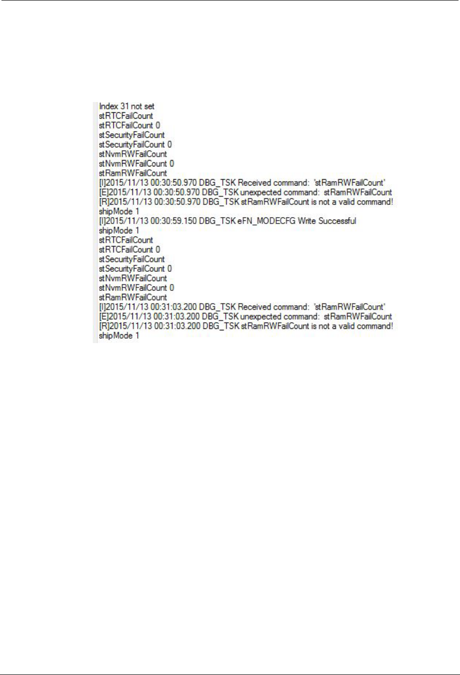
6. Click on Power Up Self Tests.
7. Verify that RTCFailCount, SecurityFailCount and NvmRWFailCount are all
set at 0.
8. Verify that shipMode 1 write was successful. (It may be necessary to click
twice to see shipMode write successful.)
9. Verify number of test records has increased on DCU Main Board
DRAFT