Aclara Technologies 9975T Aclara Synergize RF Network DCU XCVR User Manual COVER SHEET FOR ASSEMBLY PROCEDURES
Aclara Technologies LLC Aclara Synergize RF Network DCU XCVR COVER SHEET FOR ASSEMBLY PROCEDURES
Contents
- 1. Users Manual
- 2. Label Instruction
- 3. User Manual
Label Instruction
Final Assembly of SCG DCU
Document No.: AP-1X700-003-MAD Rev. D Page 1 of 12
Proprietary Document and Information of Aclara
Uncontrolled when printed unless marked ‘Controlled’ or ‘Production Copy’ with a date in red
All SCG DCU
Product Family(s)
501-9975VERLT1R1-SCG
501-9975VERST1R1-SCG
501-9975ATTLT1R1-SCG
501-9975ATTST1R1-SCG
Product P/N(s) this Document Covers
REVISIONS
Rev.
Description of Change(s)
ECO/DCN
A
Initial Release
12-00808
B
Add: 11700-CELL-SOL-SCG, redesigned to use compact enclosure.
Remove: All references to Ascendant and full size enclosure.
Remove: Auxiliary FCC label.
12-02139
C
Add: Reference to Test Procedure 465-11700-02-PTI for security switch hardware.
Add: Requirement for operator to stamp switch bracket after successful test.
Add: Striker plate for security switch.
13-00361
D
Change: Title reference from 1X700 to SCG.
Remove: Reference to 1X700 DCUs.
Add: Reference to new 501-9975VER* and 501-9975ATT* DCUs.
Add: Placement of SimCard remnant into vinyl pouch.
14-00591
Final Assembly of SCG DCU
Document No.: AP-1X700-003-MAD Rev. D Page 2 of 12
Proprietary Document and Information of Aclara
Uncontrolled when printed unless marked ‘Controlled’ or ‘Production Copy’ with a date in red
1.0 Scope:
1.1 This procedure details the final assembly process for all SoCal Gas (SCG) DCUs.
Section 4.1: Final assembly of plastic box (electronics package).
Section 4.2: Installation of the enclosure cover.
Section 4.3: Placement of product labels.
2.0 General Safety and Work Area Guidelines:
2.1 Eye protection shall be worn in the assembly area at all times.
2.2 All personnel shall review and follow the requirements documented on the MSDS of any substance used in
product assembly.
2.3 All personnel performing this procedure must be trained and follow the “ESD Testing and Daily Check
Procedure”.
2.4 All personnel performing this procedure must be adequately qualified and trained in the safe and proper use
of shop tools.
2.5 Beware of possible sharp edges and corners on sheet metal parts.
2.6 The following graphical symbols are used in this document to bring special attention to certain aspects of
the process.
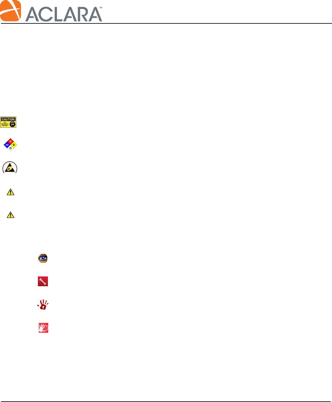
An eye is used to identify notes or inspection items which are important and may be easily
overlooked.
The wrench indicates that a tool is required for assembly. This symbol is applied universally, in this
document, to represent any tool, not just a wrench.
The symbol is adverse to the wrench/tool symbol. This indicates that the assembly must be by hand
and without the aid of a tool.
This symbol is used to point out a surface or area which must be prepared in some way. The text will
provide information on how it should be prepared.
Final Assembly of SCG DCU
Document No.: AP-1X700-003-MAD Rev. D Page 3 of 12
Proprietary Document and Information of Aclara
Uncontrolled when printed unless marked ‘Controlled’ or ‘Production Copy’ with a date in red
2.7 Table 1 provides a list of tools and materials which are required to perform this procedure. Materials
called out here are in addition to those already included on the product bill of material (BOM).
Quantity
Description
As Req’d
Isopropyl Alcohol
1
Screwdriver, flat, 6” long x 5/16” blade or larger
1
Pneumatic Torque Driver
1
Torque Tester, Mountz M-100 or equivalent
1
3/8” Drive Socket Set
Table 1
3.0 Related Documents:
501-9975VERLT1R1-SCG-DWG, Assembly Drawing
501-9975VERST1R1-SCG-DWG, Assembly Drawing
501-9975ATTLT1R1-SCG-DWG, Assembly Drawing
501-9975ATTST1R1-SCG-DWG, Assembly Drawing
465-11700-02-PTI, Door - Switch Test Instruction
Final Assembly of SCG DCU
Document No.: AP-1X700-003-MAD Rev. D Page 4 of 12
Proprietary Document and Information of Aclara
Uncontrolled when printed unless marked ‘Controlled’ or ‘Production Copy’ with a date in red
4.0 Procedure:
4.1 Complete assembly of plastic box.
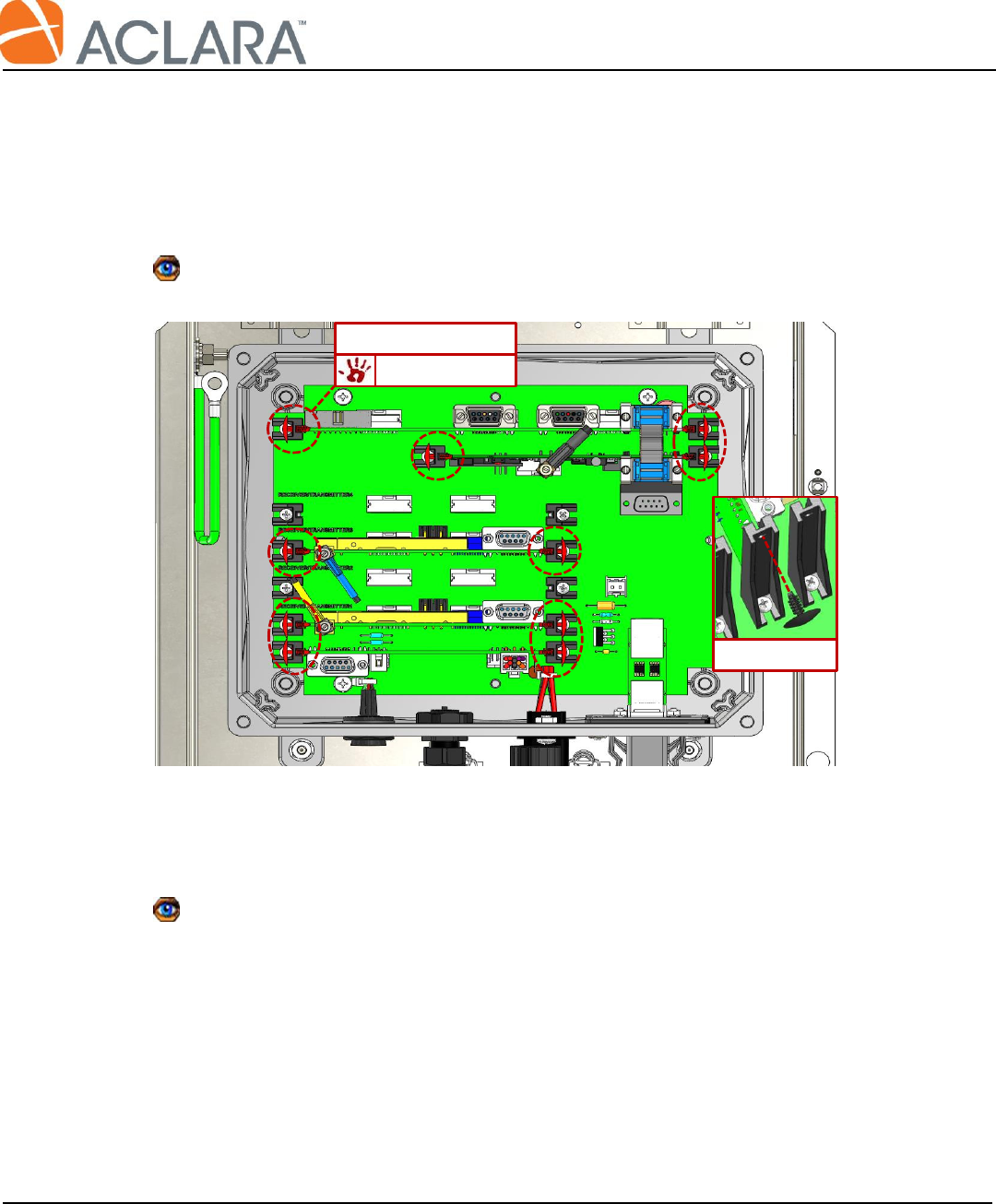
4.1.1 Install (10) barbed printed circuit board (PCB) retainers. These are manually pushed into the
holes provided in each PCB slide rail.
Install ALL (10) retainers in the position shown in Figure 2, even if there is no PCB installed.
4.1.2 Place clear plastic box cover p/n 056-9975 over the top of the plastic box.
Insure the (4) corner screws for the plastic cover are in place, but DO NOT tighten them down at
this time. They will be tightened by QA upon completing final inspection/audit.
Retainer
069-0080 (x10)
Figure 2: Install Barbed PCB Retainers
Detail
Final Assembly of SCG DCU
Document No.: AP-1X700-003-MAD Rev. D Page 5 of 12
Proprietary Document and Information of Aclara
Uncontrolled when printed unless marked ‘Controlled’ or ‘Production Copy’ with a date in red
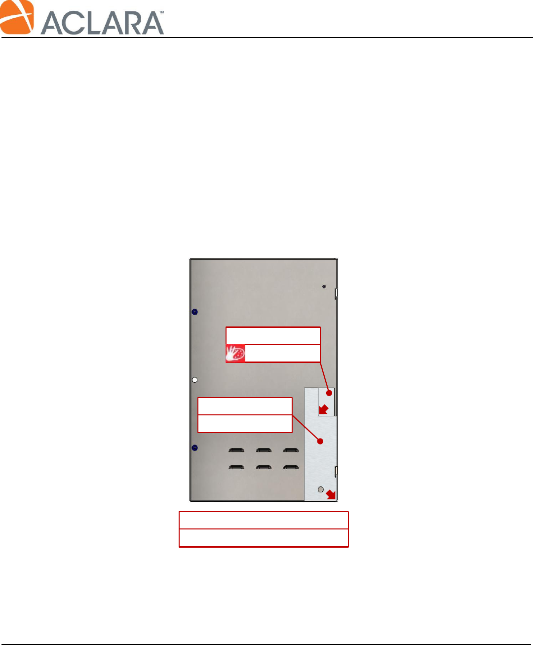
4.2 Assemble and install the DCU cover.
4.2.1 Install the strike plate (056-9975X-2) as shown in Figure 3.
Using a clean cloth and Isopropyl Alcohol, clean the surface where the strike plate is to be
installed.
Orient fixture FIX-1X700-002 as shown, holding the corner of the fixture firmly into the inside
corner of the enclosure cover.
Remove the paper backing of the strike plate and place using the inside corner of the fixture as a
guide.
Remove the fixture press the strike place firmly to insure complete adhesion to the stainless steel
cover.
Figure 3: Install Strike Plate
056-9975X-2
Inside of Enclosure Cover
056-10700-2
Strike Plate
Fixture
FIX-1X700-002
Final Assembly of SCG DCU
Document No.: AP-1X700-003-MAD Rev. D Page 6 of 12
Proprietary Document and Information of Aclara
Uncontrolled when printed unless marked ‘Controlled’ or ‘Production Copy’ with a date in red
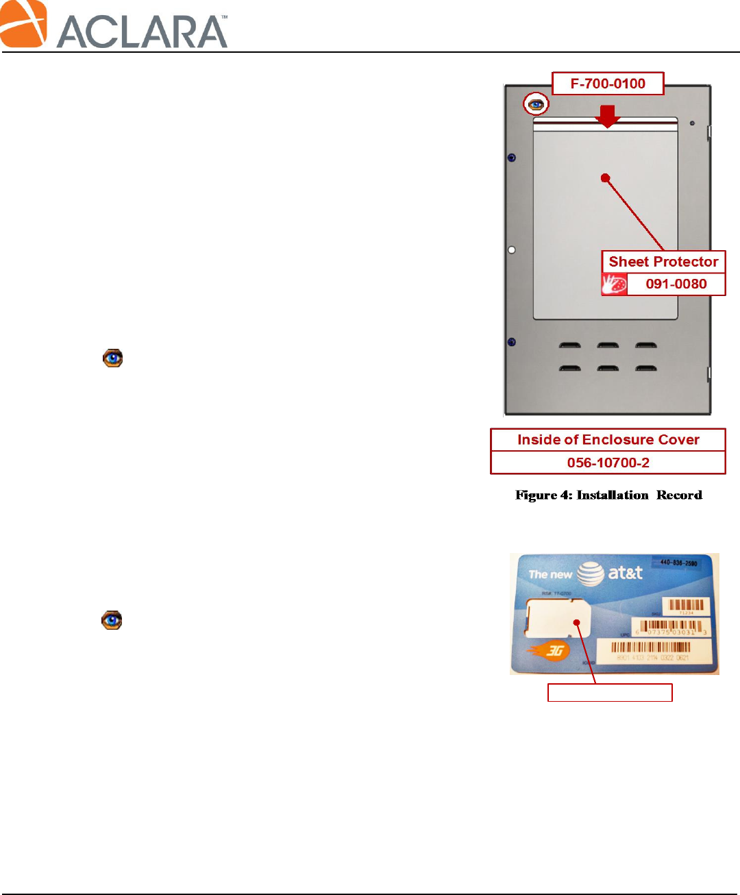
4.2.2 Add the Installation & Maintenance Record form
with vinyl sheet protector to the inside of the
enclosure cover as shown in Figure 4.
Clean the inside surface of the enclosure cover with
Isopropyl Alcohol to remove any oil or
contaminants.
Remove paper backing from the sheet protector.
With the red zipper seal towards the top edge of the
cover, center the sheet protector on the inside of the
cover as shown and smooth down by hand.
4.2.3 Check form F-700-0100 provided with the DCU by
the Test Technician:
DCU ID on form and ALL (3) ID Labels
inside DCU match.
Model on form matches the Item Number on
the work order.
Final test date and technician must be filled
out.
4.2.4 Insert form F-700-0100 into the sheet protector.
4.2.5 Check that the Test Technician provided the remaining
portion of the SimCard similar to the one shown in
Figure 4B. Cards from different service providers,
such as Sprint or Verizon, may look different.
Verify the DCU ID is written on the back of the
card with black permanent marker and matches
up with the appropriate DCU.
4.2.6 Insert the remaining portion of the SimCard into the
sheet protector on top of the maintenance form, so that
it is clearly visible.
4.2.7 Fully seal the the zip lock top of the sheet protector.
Figure 4B: Sample Sim Card
Sim Card Was Here
Final Assembly of SCG DCU
Document No.: AP-1X700-003-MAD Rev. D Page 7 of 12
Proprietary Document and Information of Aclara
Uncontrolled when printed unless marked ‘Controlled’ or ‘Production Copy’ with a date in red
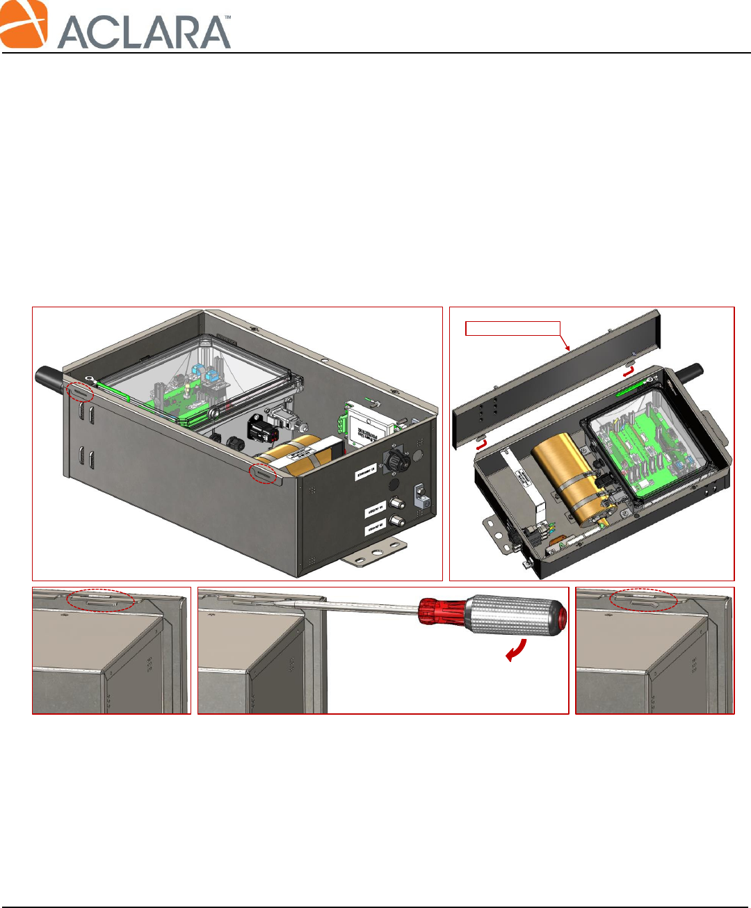
4.2.8 On the top left edge of the enclosure are (2) slots for mounting the cover; see Figure 5-I.
Holding the cover as shown in Figure 5-II, place both tabs, on the covers edge, into the slots of
the enclosure. With the tabs in both slots, the cover should slide about ¼” toward the bottom of
the enclosure.
Close the enclosure cover and observe that the tab and slot mate up as shown in Figure 5-III.
Place the blade of a large screwdriver behind one of the cover tabs as shown in Figure 5-IV and
bend the tab to a 20-30O angle as shown in Figure 5-V.
Bend the second tab in the same manner.
Figure 5: Install Enclosure Cover
Enclosure Cover
I
II
III
IV
V
Final Assembly of SCG DCU
Document No.: AP-1X700-003-MAD Rev. D Page 8 of 12
Proprietary Document and Information of Aclara
Uncontrolled when printed unless marked ‘Controlled’ or ‘Production Copy’ with a date in red
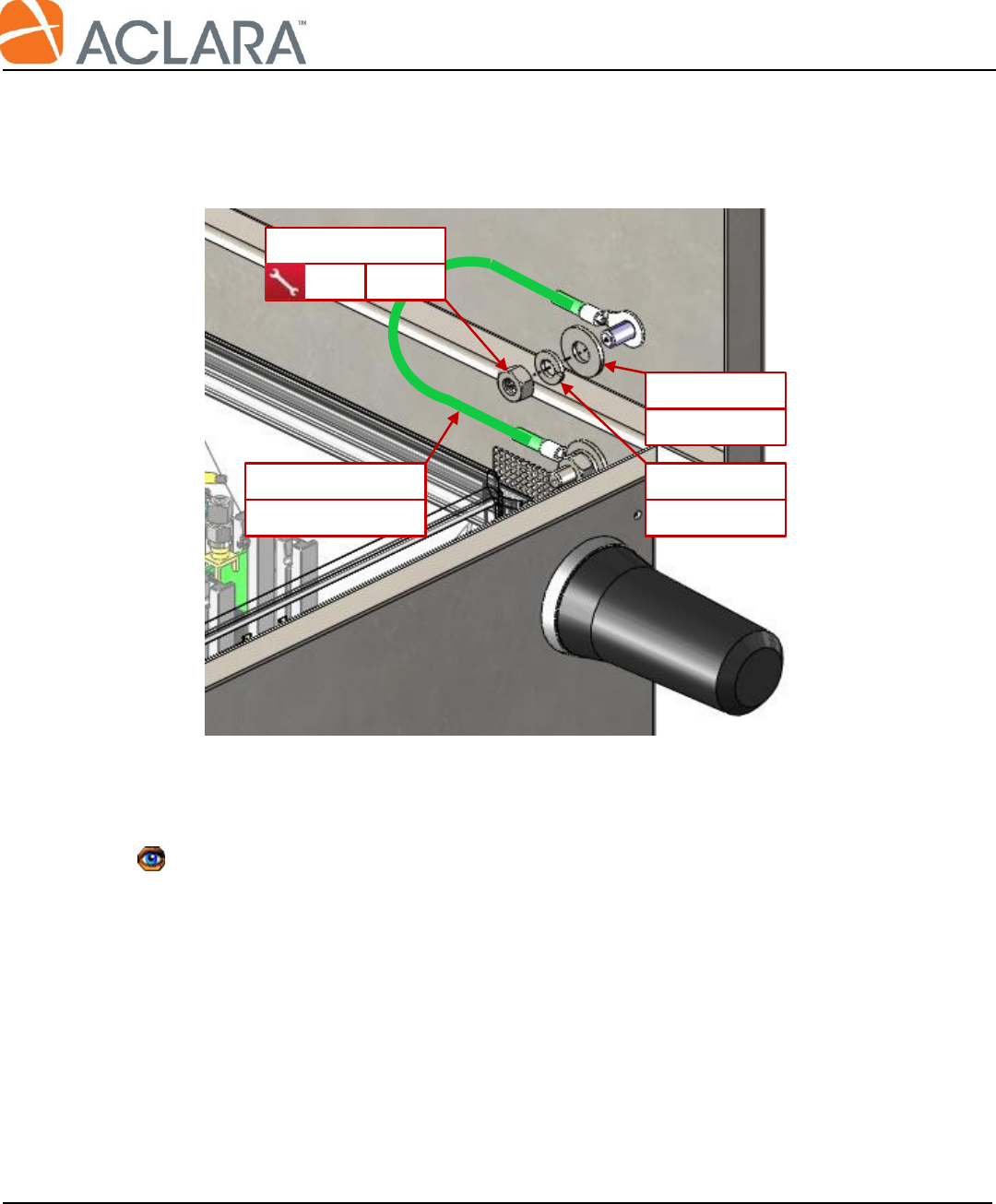
4.2.9 Connect the bonding jumper to the enclosure cover as shown in Figure 6.
4.2.10 Test security switch hardware per procedure 465-11700-02-PTI.
Upon successful completion of test, the operator shall place their stamp on a clearly visible
location of the switch bracket. The mark may be used by QA as a visual queue that the security
switch hardware was verified to function properly after the DCU cover was installed.
069-3202A
Split Washer
069-3201A
Flat Washer
070-10700
Bonding Jumper
Figure 6: Connect Bonding Jumper
069-3215LS
7/16"
35 in-lb
Final Assembly of SCG DCU
Document No.: AP-1X700-003-MAD Rev. D Page 9 of 12
Proprietary Document and Information of Aclara
Uncontrolled when printed unless marked ‘Controlled’ or ‘Production Copy’ with a date in red
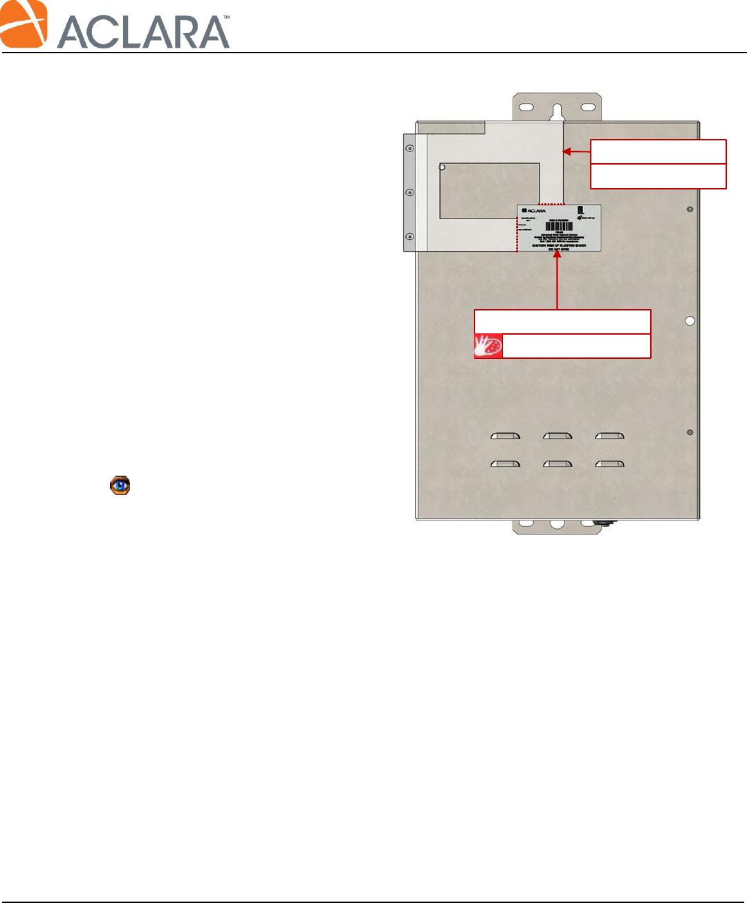
4.3 Placement of product labels.
4.3.1 Refer to Figure 7 for installation of
the DCU FCC/IC ID label.
Clean the surface of the enclosure
with Isopropyl Alcohol.
Place the fixture in the orientation
shown. Align the fixture square with
the top-left corner of the enclosure
cover using the guide rail and the top
edge of the fixture as shown.
Remove the paper from the adhesive
back of the label.
Hold the fixture firmly in place and
use the reference edges of the fixture
to position the DCU FCC/IC ID label.
Verify the label position is square to
the corner of the cover then press
down all edges of the label firmly by
hand.
Figure 7: Install DCU FCC/IC ID Label
091-11700-SCG-1
DCU ID Label
FIX-1X700-001
Fixture
Final Assembly of SCG DCU
Document No.: AP-1X700-003-MAD Rev. D Page 10 of 12
Proprietary Document and Information of Aclara
Uncontrolled when printed unless marked ‘Controlled’ or ‘Production Copy’ with a date in red
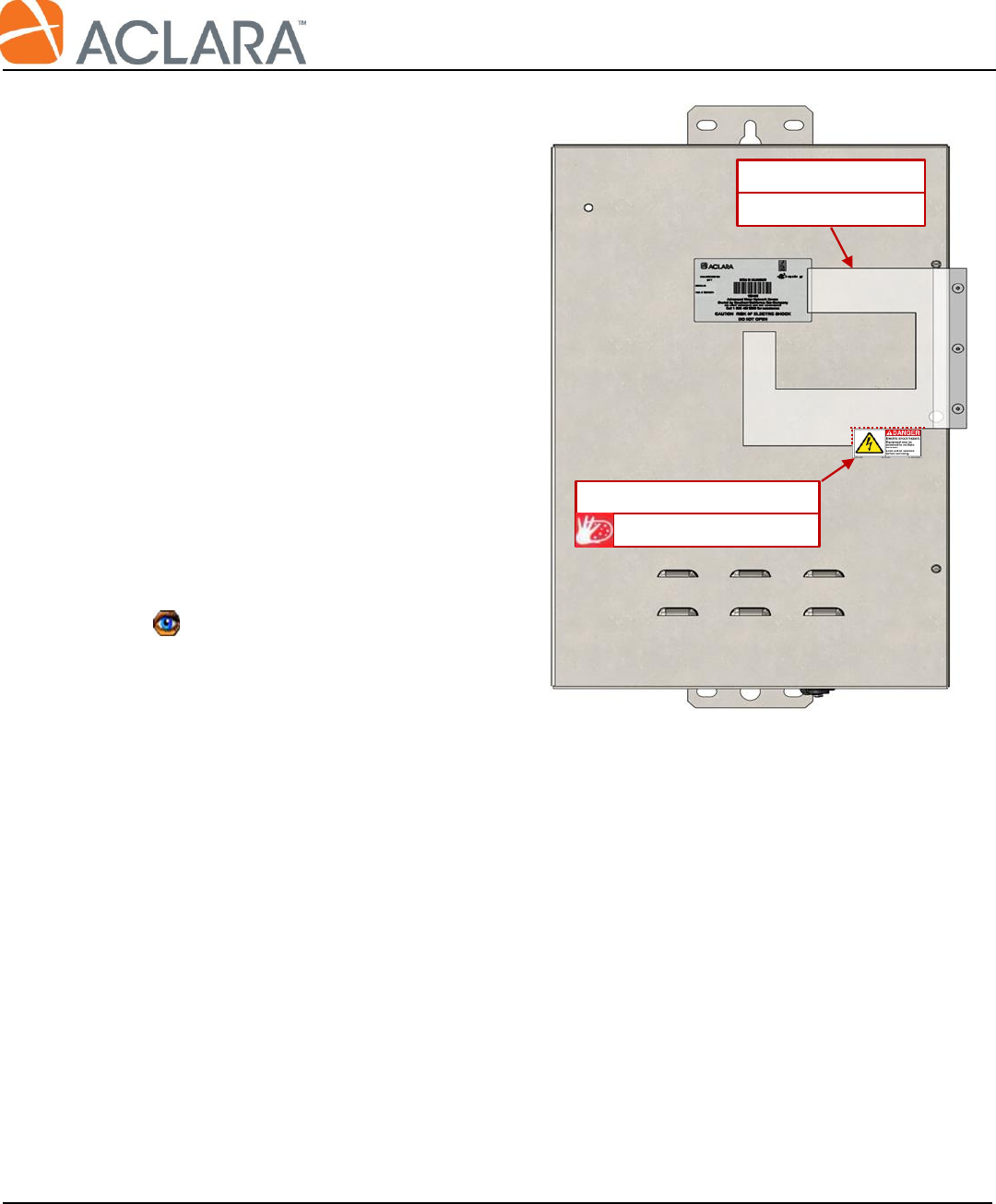
4.3.2 Refer to Figure 8 for installation of
the Hazard label.
Clean the surface of the enclosure with
Isopropyl Alcohol.
Place the fixture in the orientation
shown. Set the fixtures guide rail to
the right edge of the enclosure cover,
then slide the fixture up until it stops
against the upper screw used to hold
the cover closed.
Remove the paper from the adhesive
back of the label.
Hold the fixture firmly in place and
use the reference edges of the fixture
to position the Hazard label.
Insure the top/bottom edges appear
perpendicular to the right edge of the
enclosure and free of wrinkles and
bubbles.
Figure 8: Install Hazard Label
091-11700-1
Hazard Label
FIX-1X700-001
Fixture
Final Assembly of SCG DCU
Document No.: AP-1X700-003-MAD Rev. D Page 11 of 12
Proprietary Document and Information of Aclara
Uncontrolled when printed unless marked ‘Controlled’ or ‘Production Copy’ with a date in red
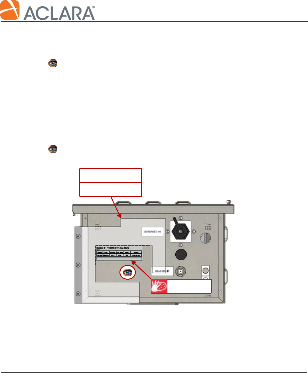
4.3.3 Refer to Figure 9 for installation of the info label.
Clean the surface of the enclosure with Isopropyl Alcohol.
There is a unique info label for every model DCU. The Model# on the label must match the item
number on the work order. Refer to the current work order or assembly print to identify the label
part number.
Place the fixture in the orientation shown. Set the fixtures guide rail to the left edge of the
enclosure, then slide the fixture down until it stops against the enclosure mounting plate.
Remove the paper from the adhesive back of the label.
Holding the fixture firmly in place, use the reference edges of the fixture to position the info
label.
Insure the top/bottom edges appear parallel to the bottom edge of the enclosure.
Figure 9: Install Info Label
Info Label
FIX-1X700-001
Fixture

Final Assembly of SCG DCU
Document No.: AP-1X700-003-MAD Rev. D Page 12 of 12
Proprietary Document and Information of Aclara
Uncontrolled when printed unless marked ‘Controlled’ or ‘Production Copy’ with a date in red
4.4 Intentionally left blank.
End of Document