AeroScout EX5700 WanderGuard BLUE EX5700 Controller User Manual 06288D
AeroScout WanderGuard BLUE EX5700 Controller 06288D
UserManual.wiki
>
AeroScout
>
EX5700 User Manual
>
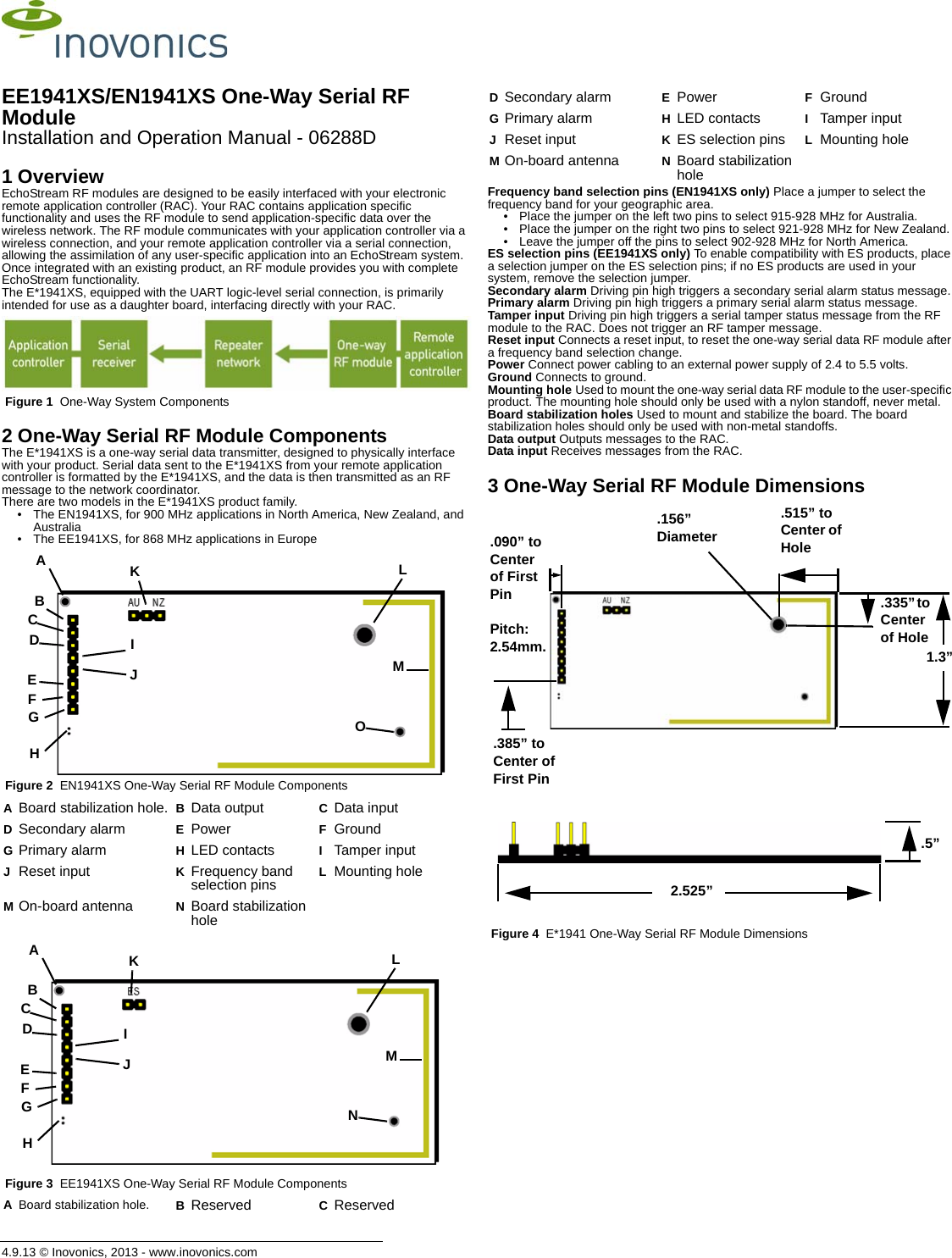
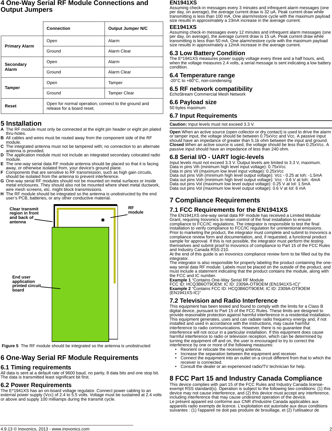
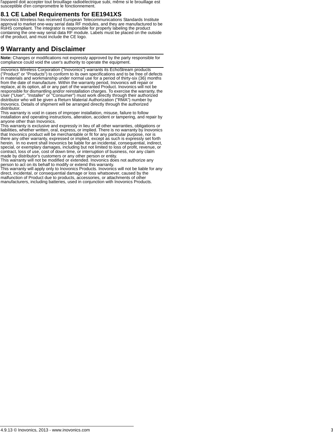
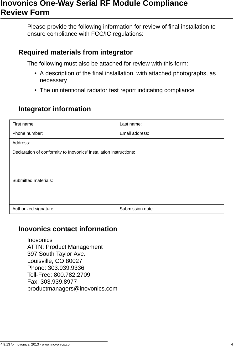
Installation and Operation Manual
Contents
1.
Installation and Operation Manual
2.
User Manual Part 1
3.
User Manual Part 2
Installation and Operation Manual
Navigation menu
Upload a User Manual
Namespaces
Wiki Guide
HTML
PDF
Info
Views
User Manual
Discussion / Help
Navigation