AeroScout EX5700 WanderGuard BLUE EX5700 Controller User Manual MobileView Analytics Patient Flow for Clinics
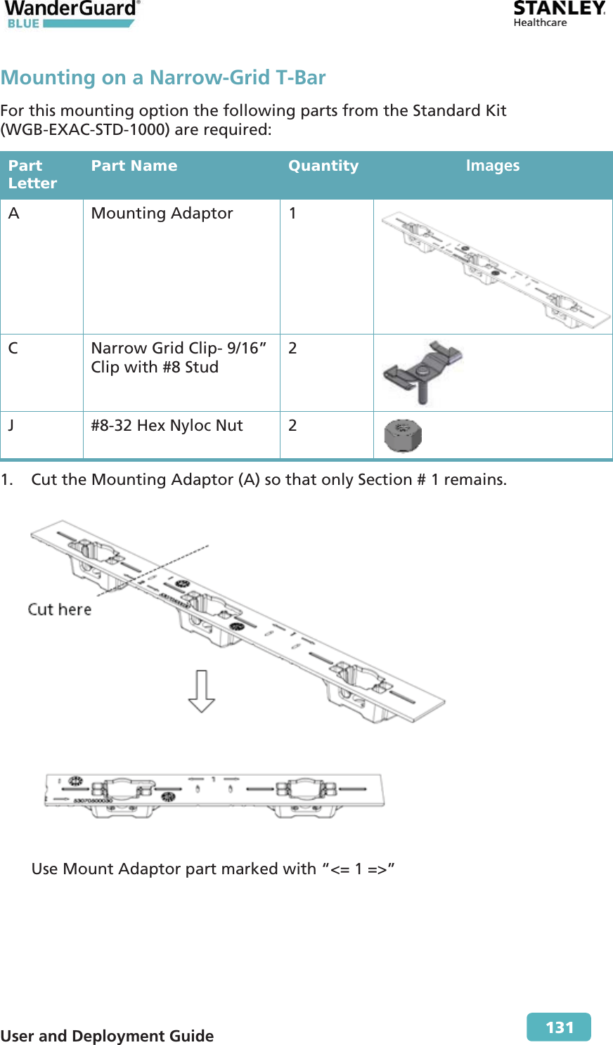
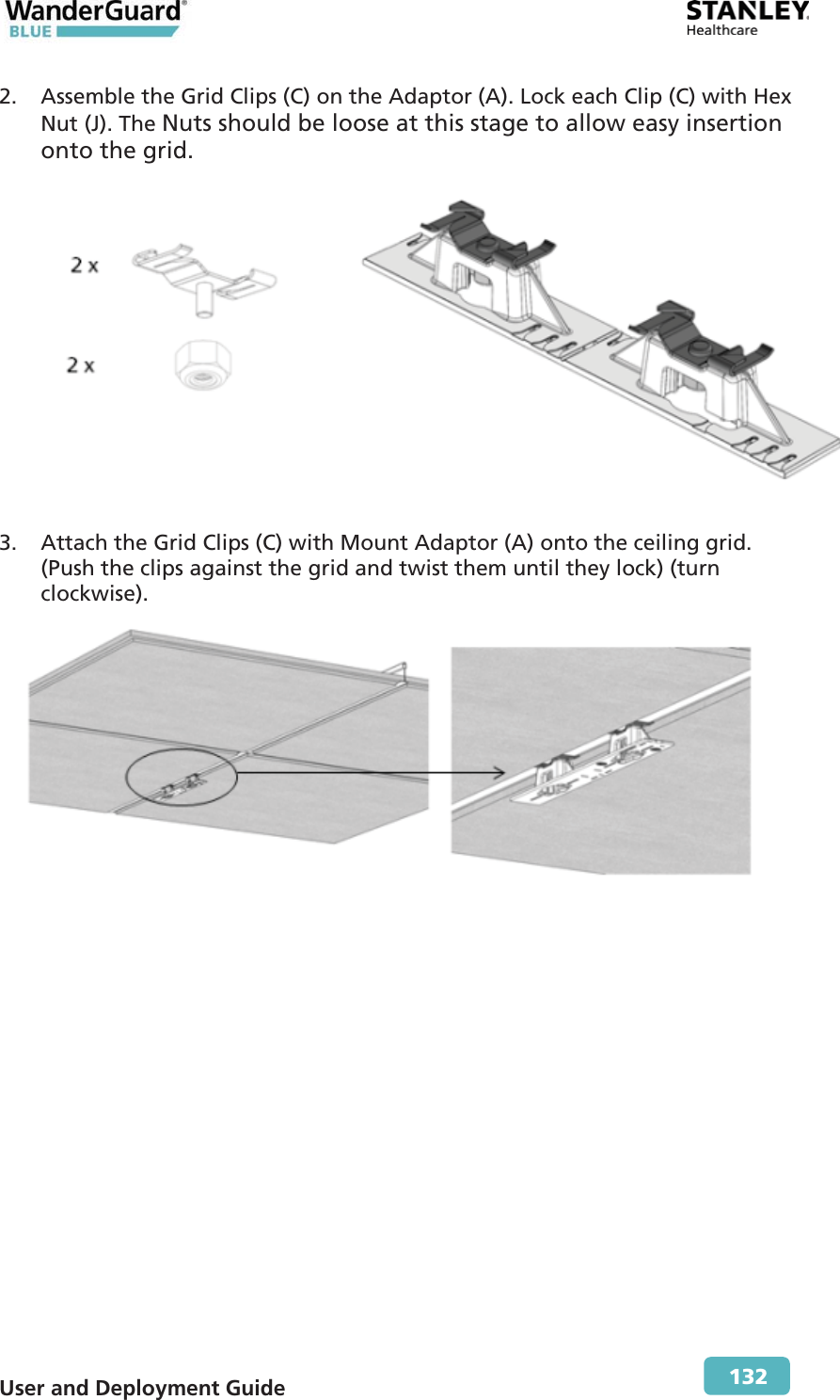
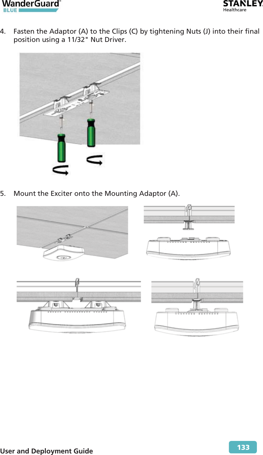
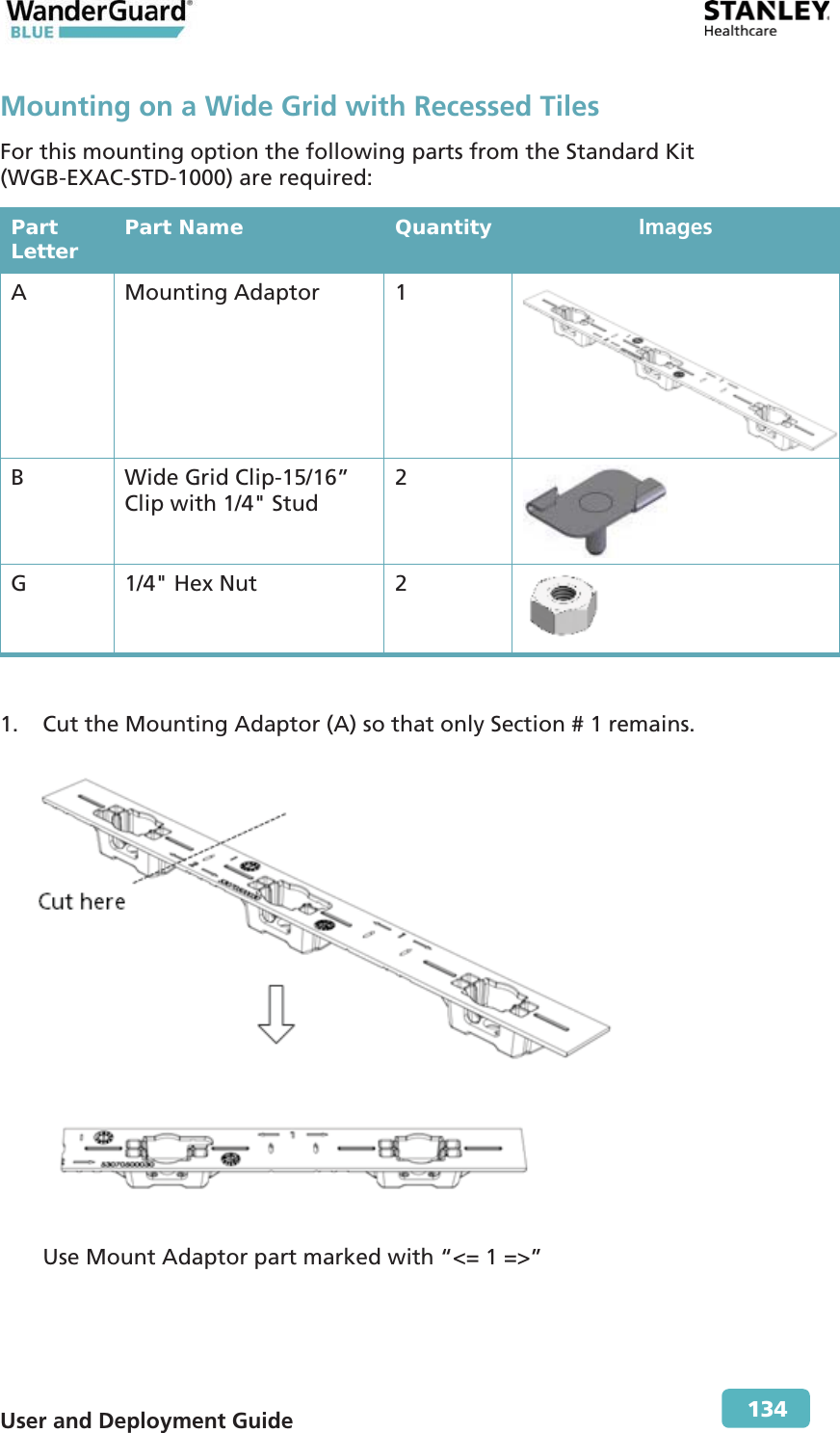
AeroScout WanderGuard BLUE EX5700 Controller MobileView Analytics Patient Flow for Clinics
Contents
- 1. Installation and Operation Manual
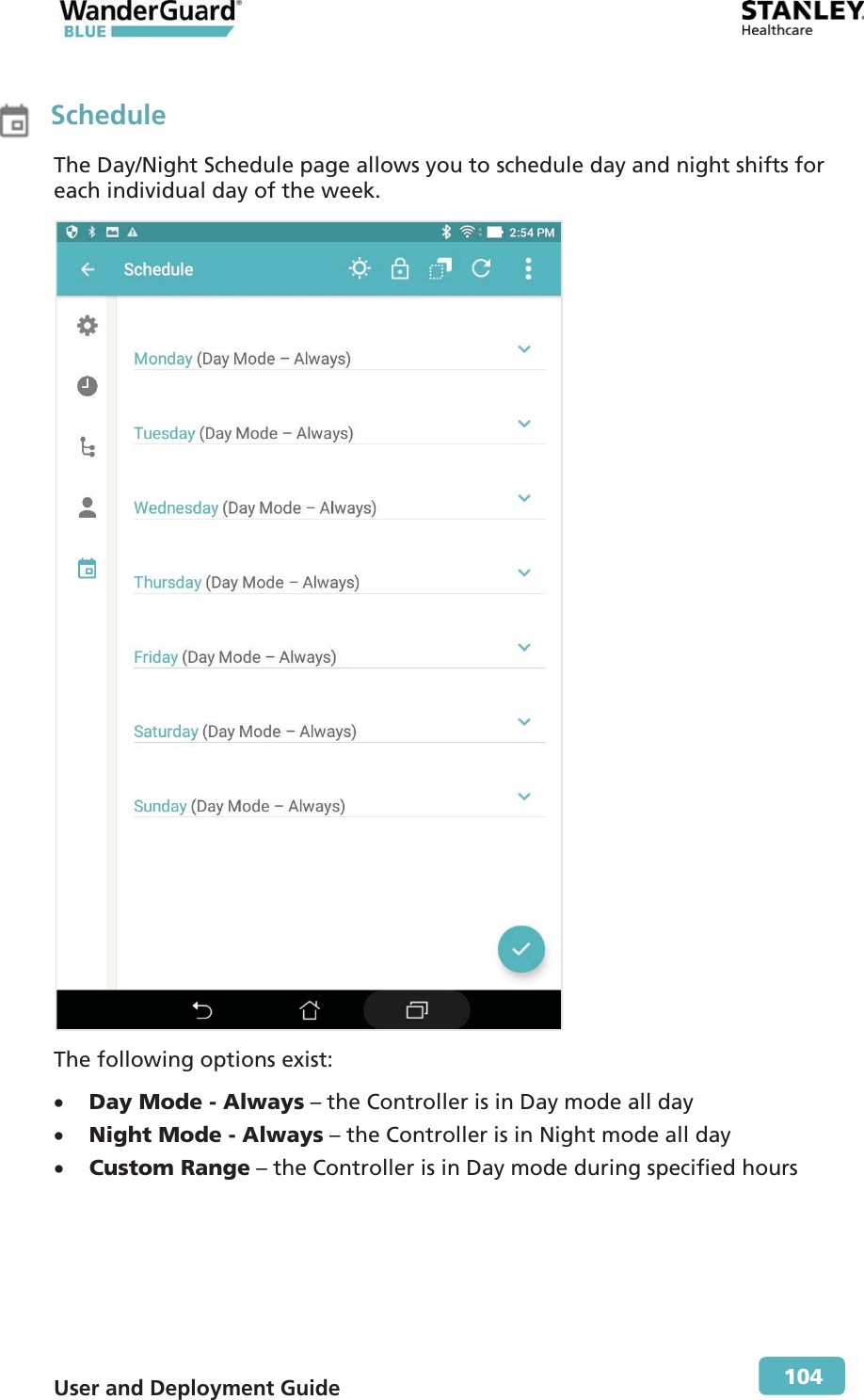
- 2. User Manual Part 1
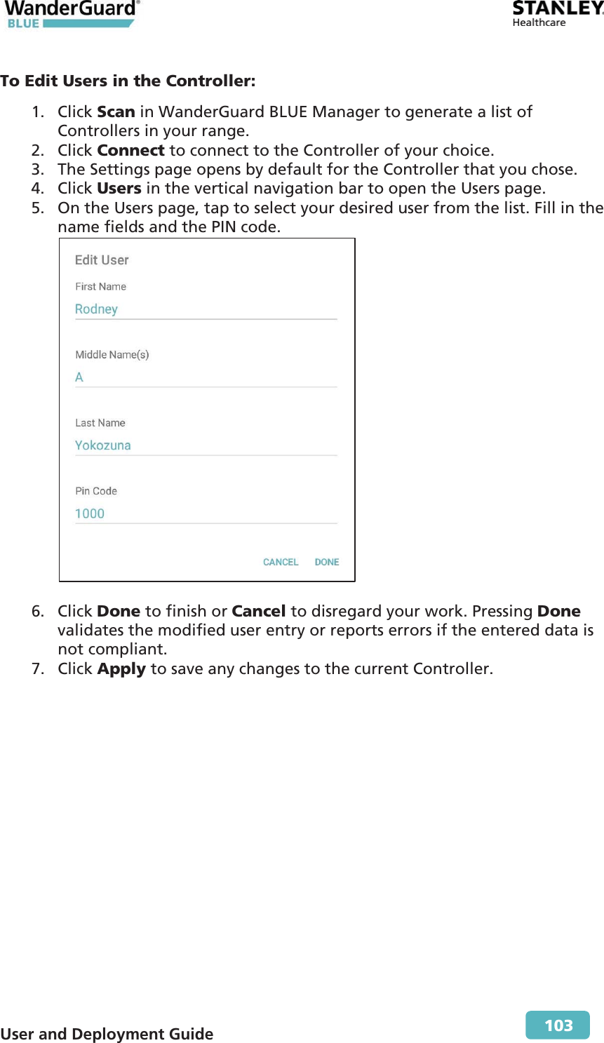
- 3. User Manual Part 2
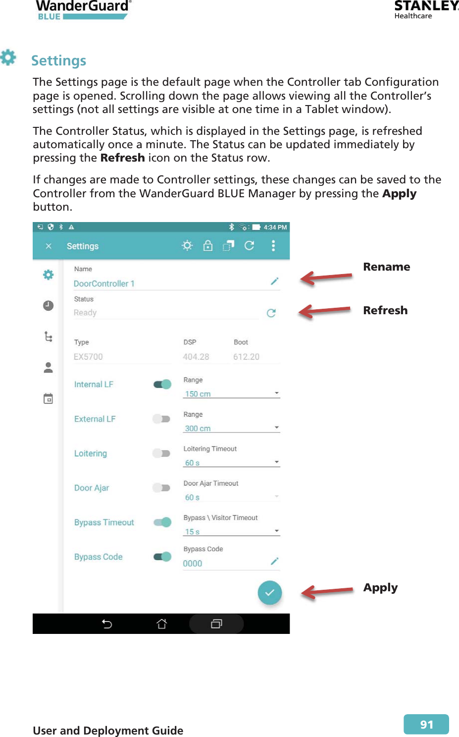
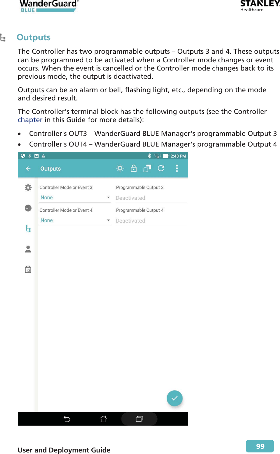
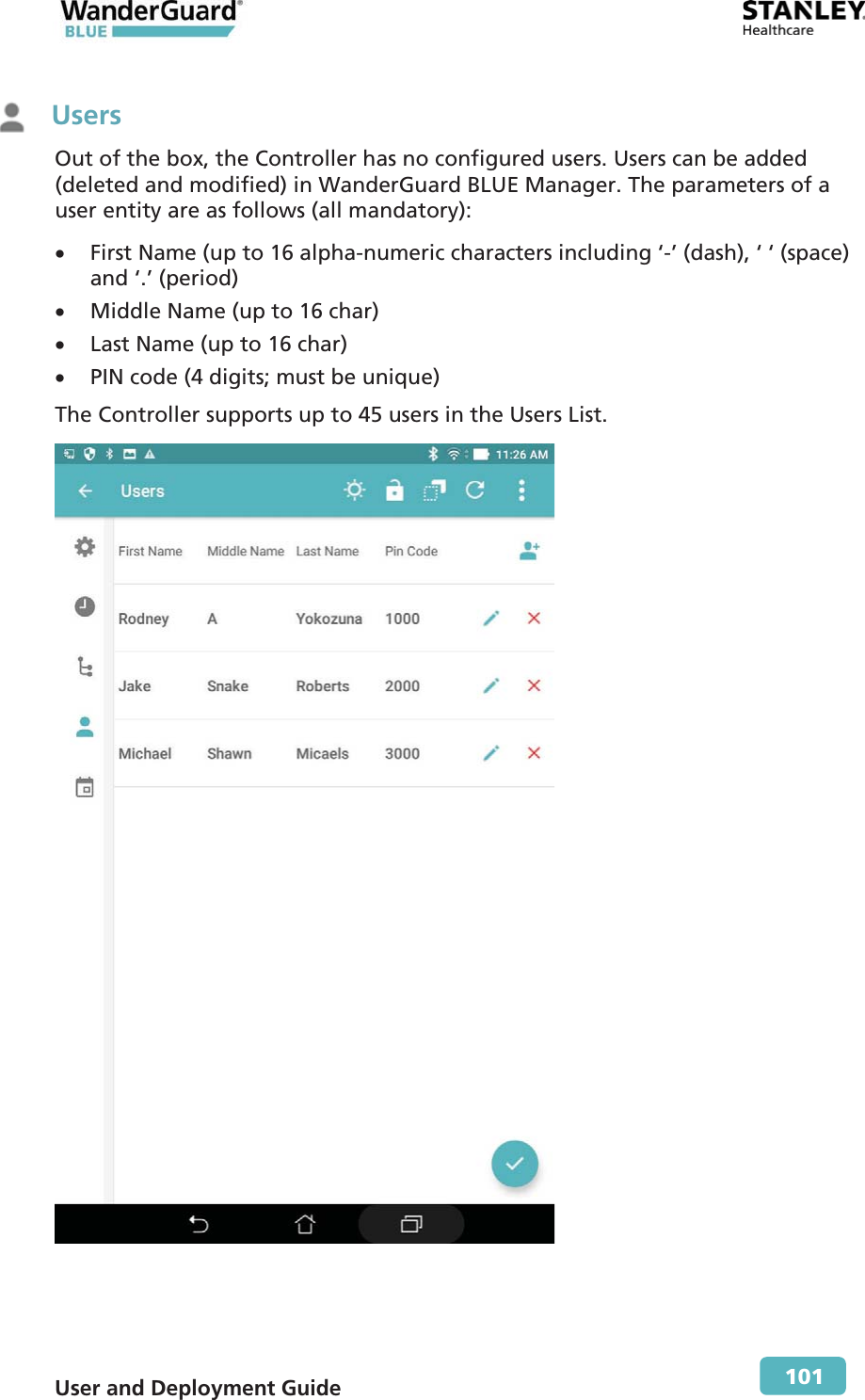
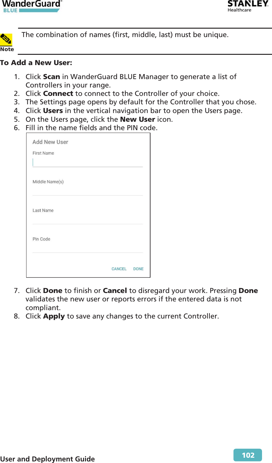
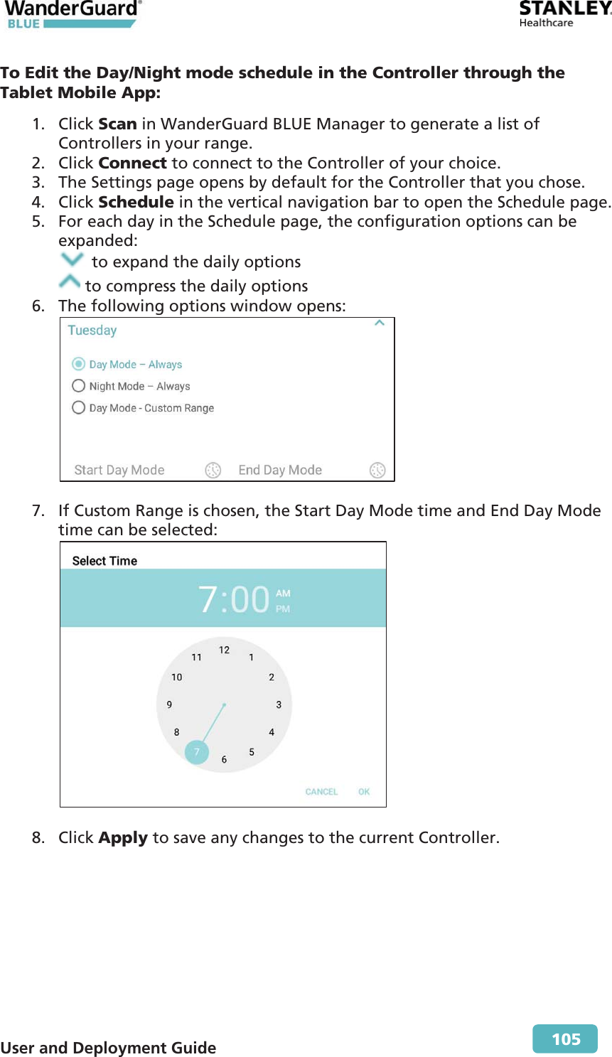
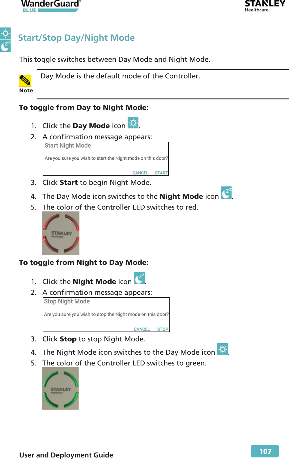
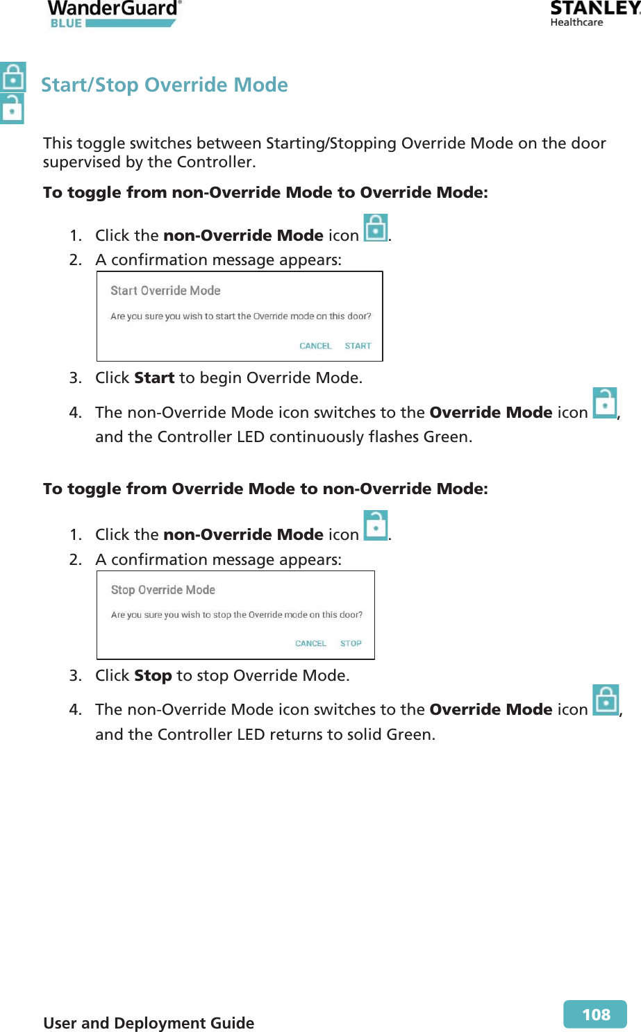
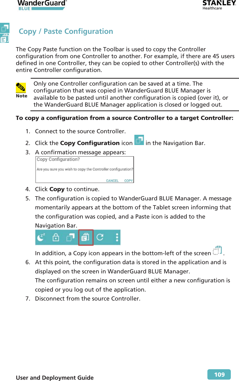
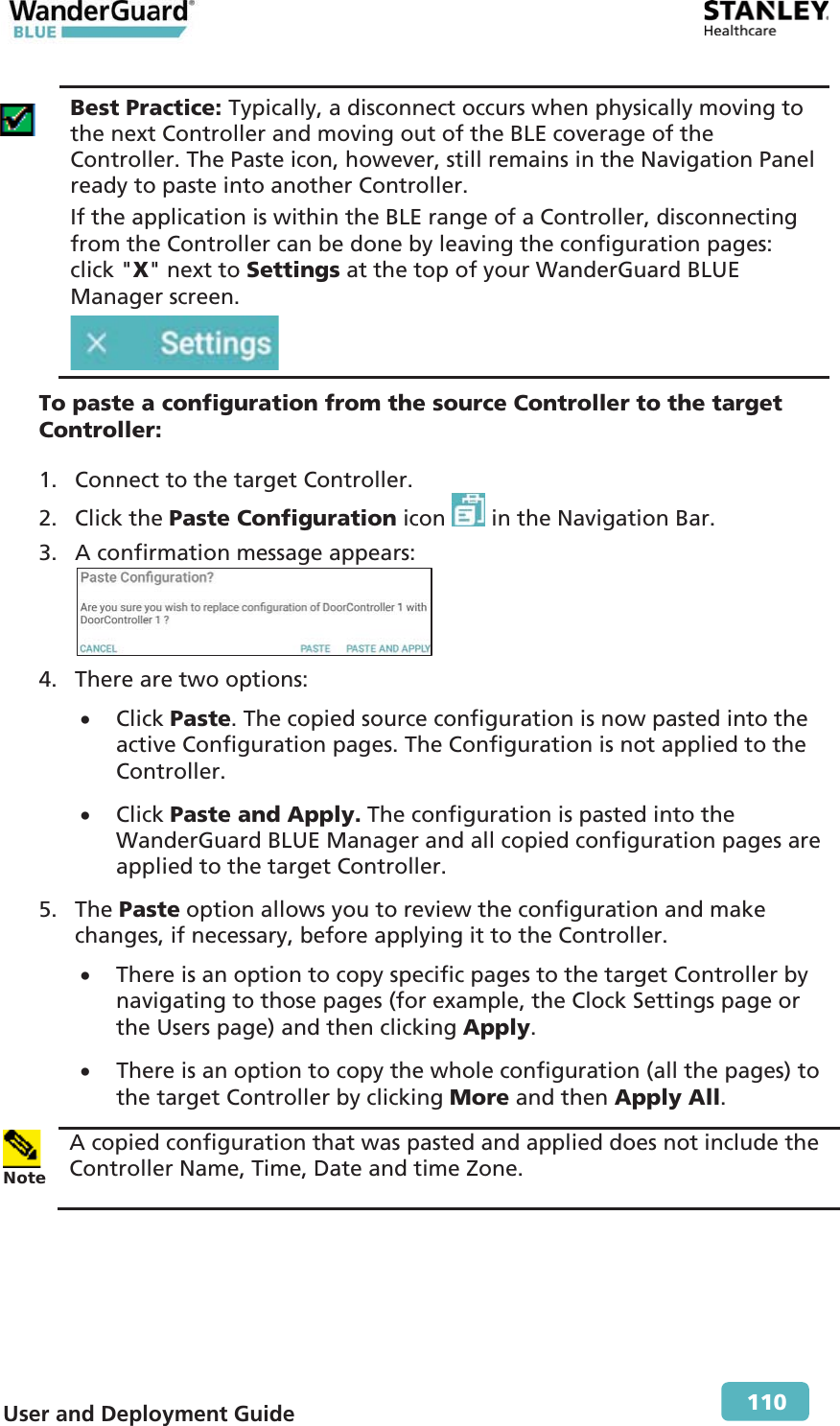
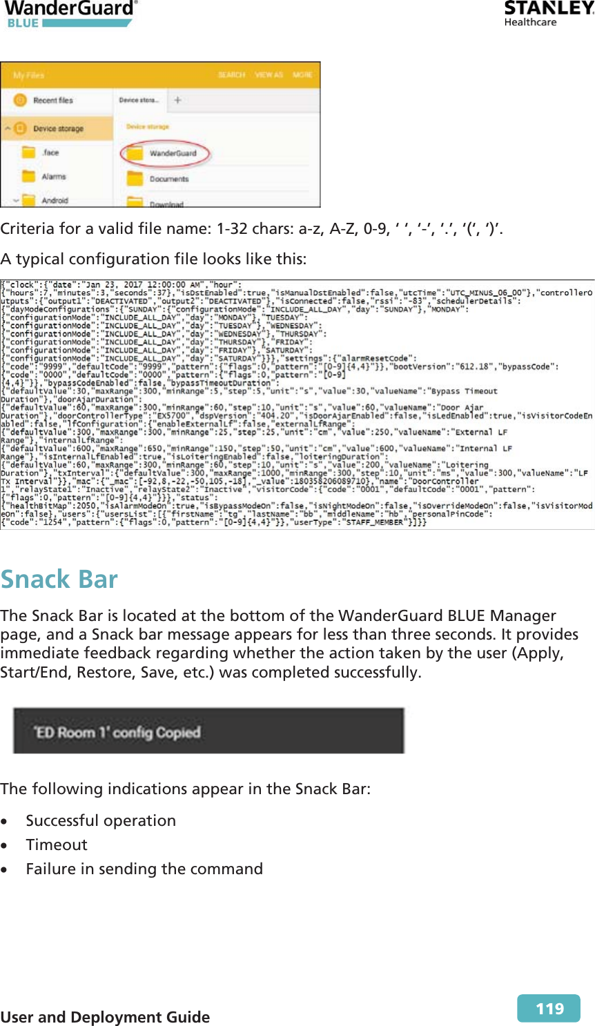
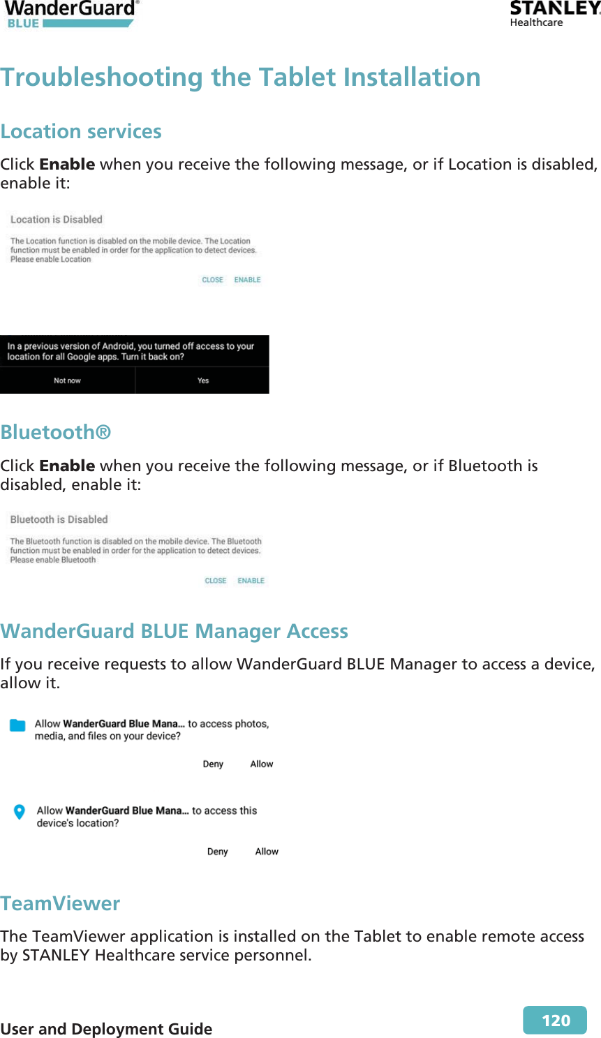
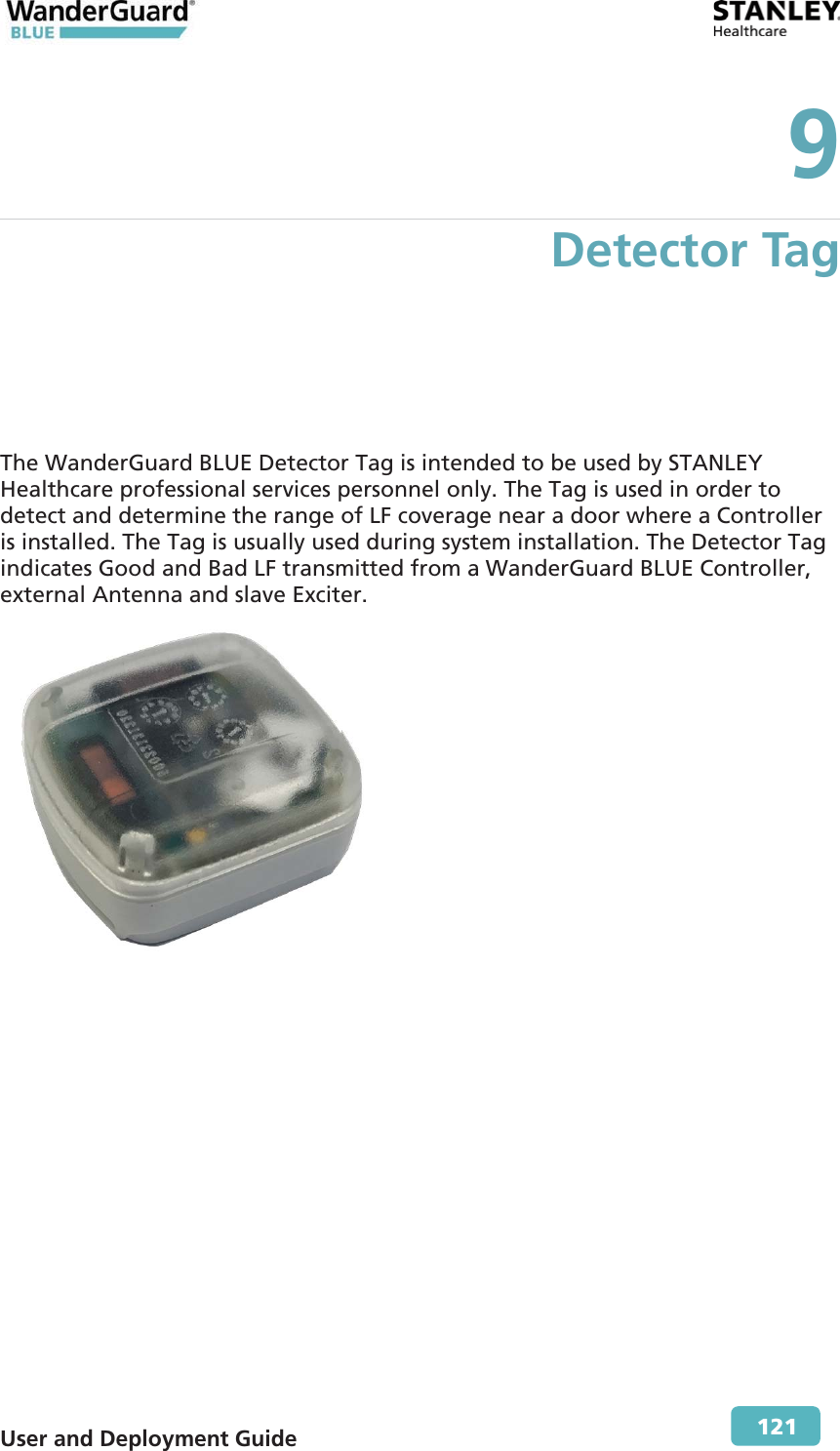
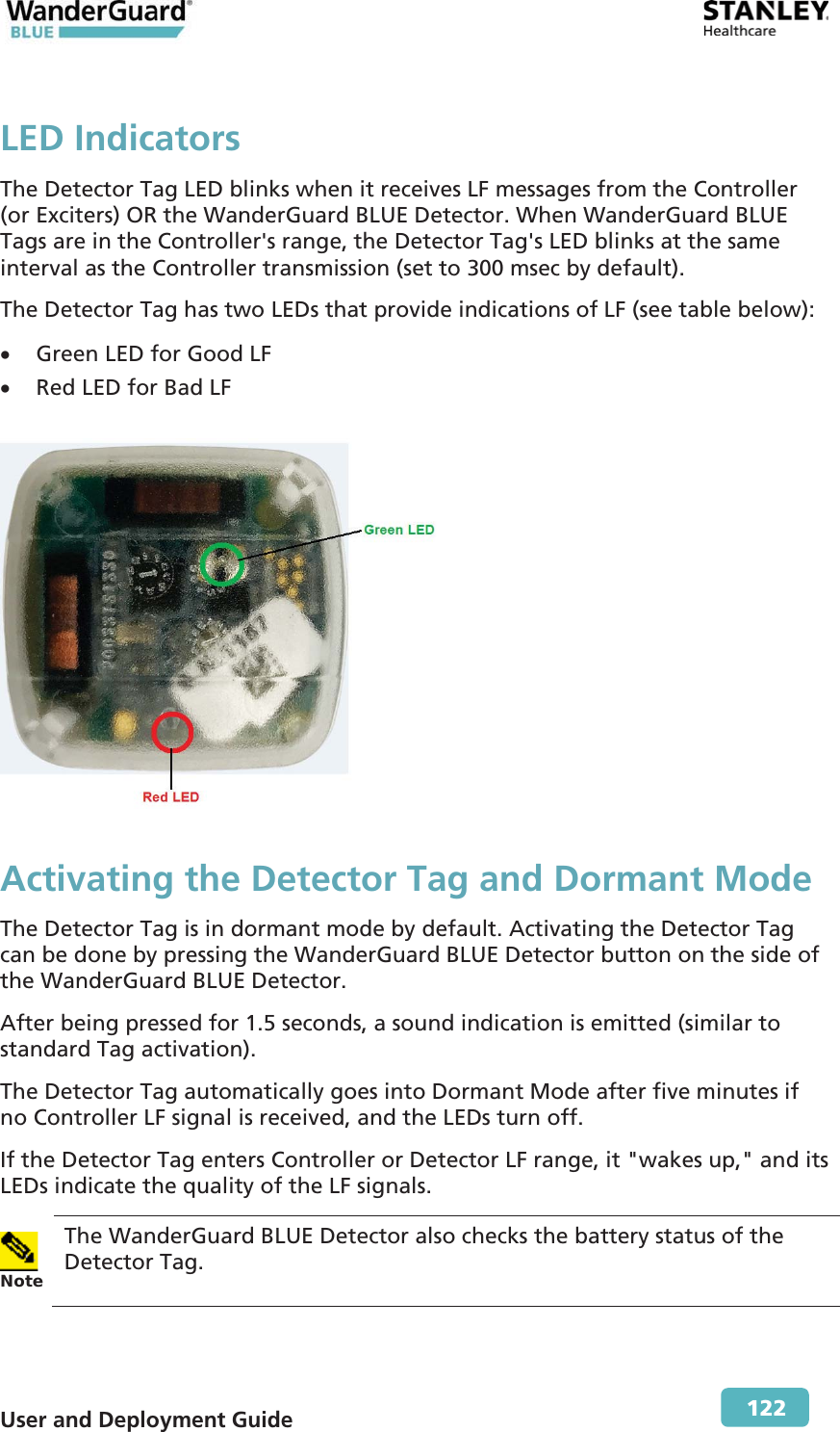
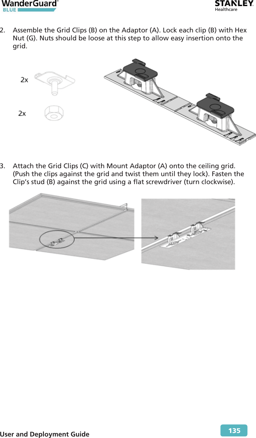
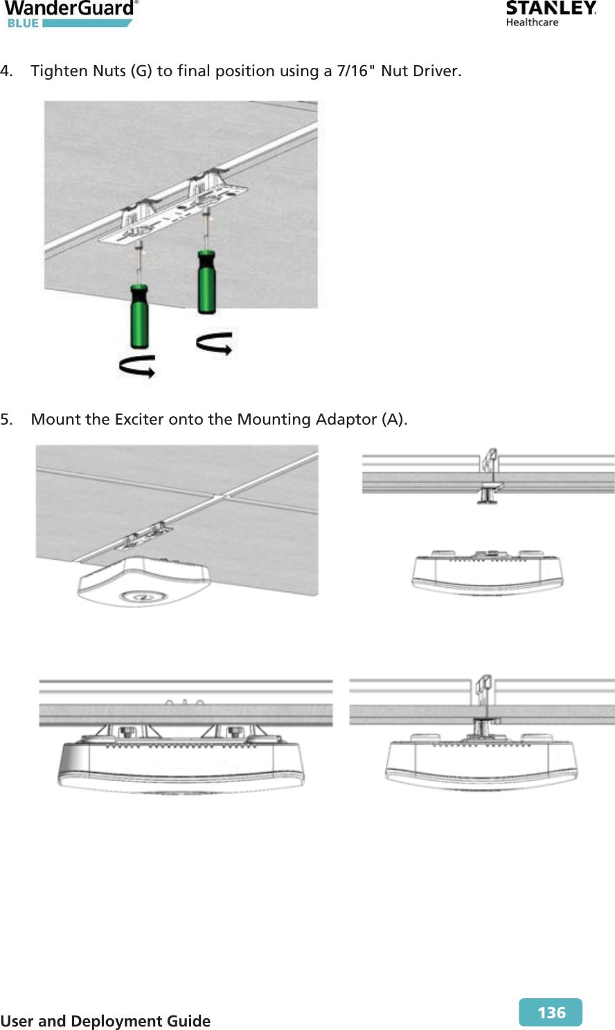
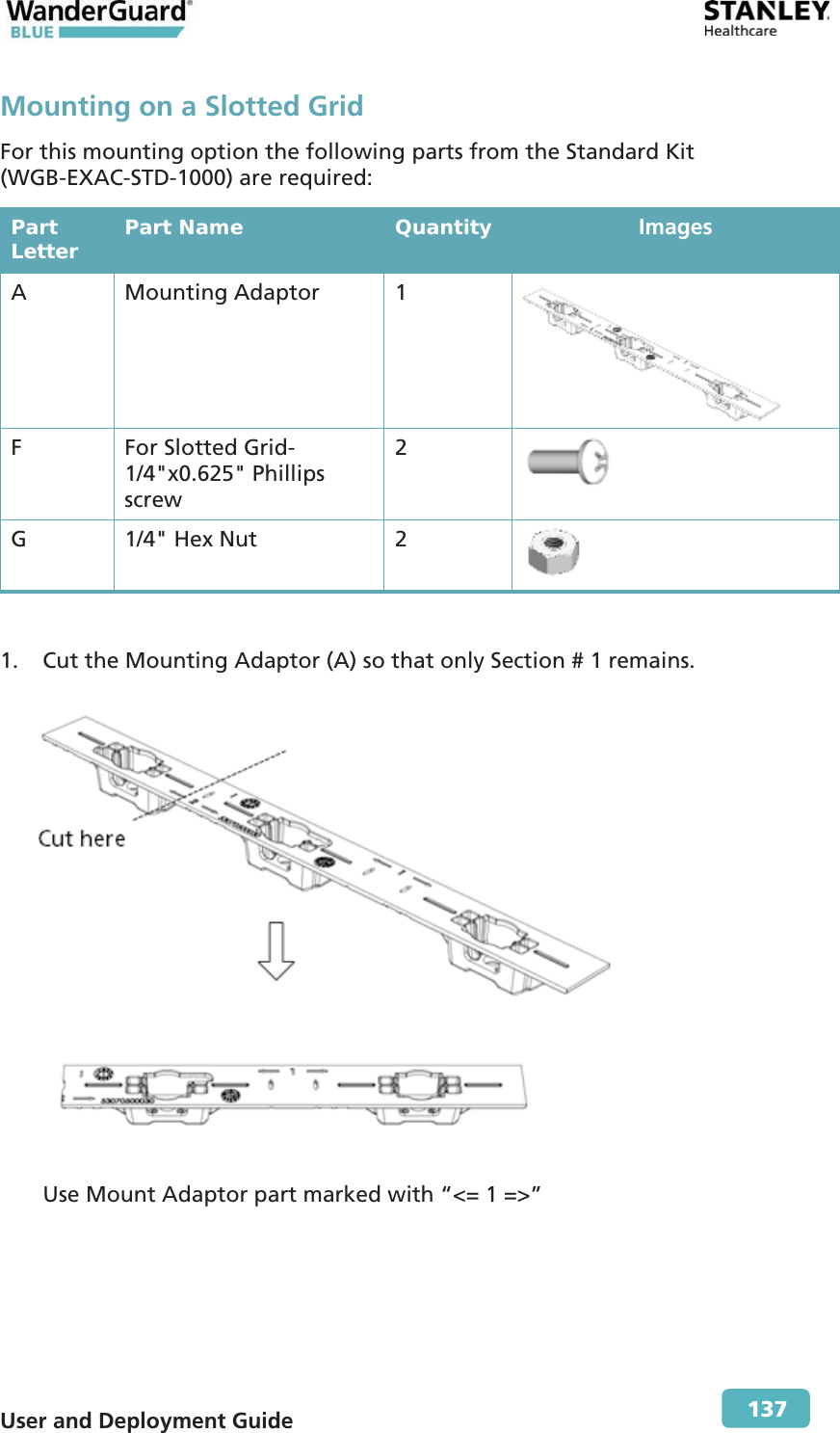
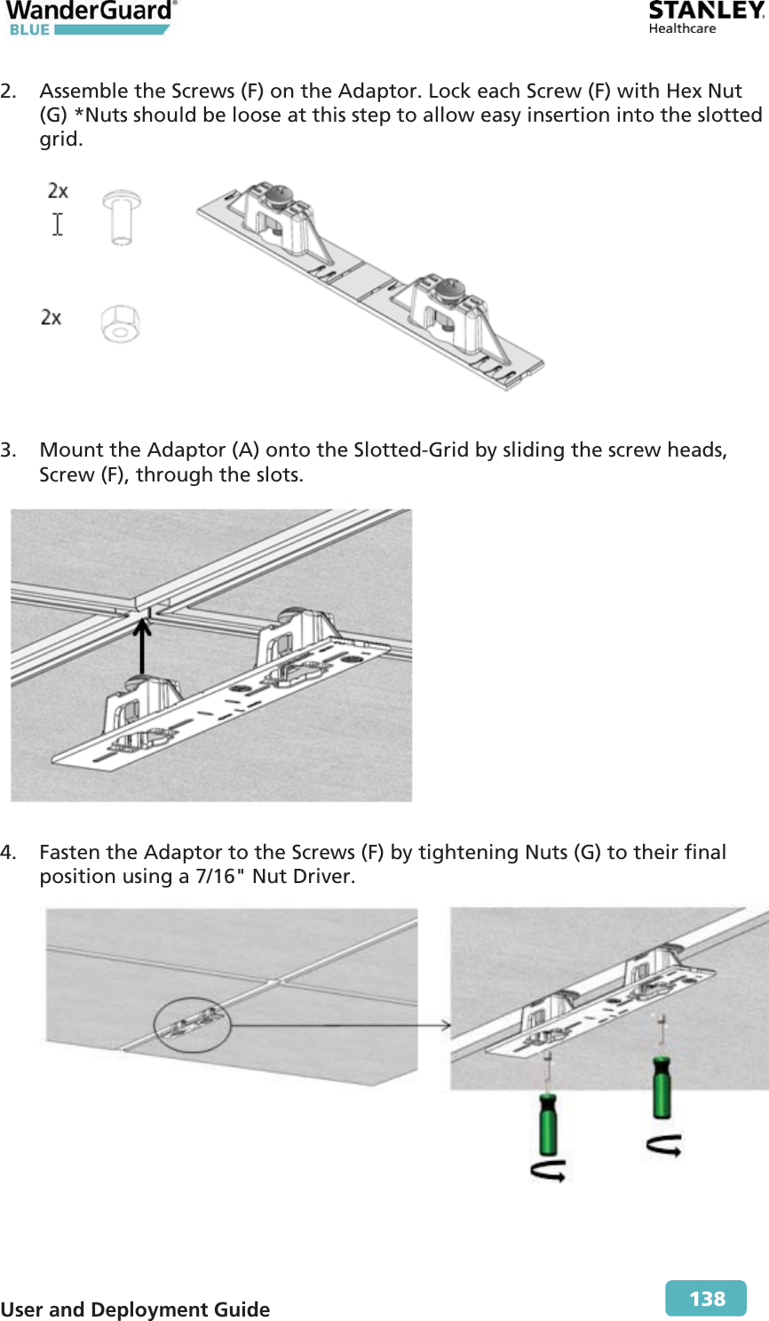
User Manual Part 2