AeroScout EX5700 WanderGuard BLUE EX5700 Controller User Manual MobileView Analytics Patient Flow for Clinics
AeroScout WanderGuard BLUE EX5700 Controller MobileView Analytics Patient Flow for Clinics
Contents
- 1. Installation and Operation Manual
- 2. User Manual Part 1
- 3. User Manual Part 2
User Manual Part 2
User and Deployment Guide
75
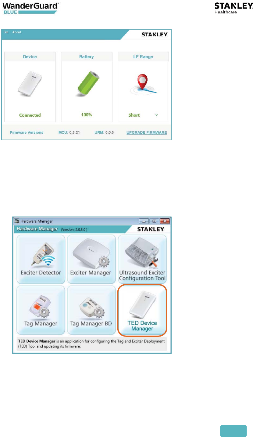
Establishing a Connection to the Detector
A connection needs to be established before the Detector’s battery status can
be viewed or firmware can be upgraded.
1. Make sure the device is connected to the PC. See Connecting the Detector
Using the USB Cable.
2. From the Hardware Manager application, click TED Device Manager.
The TED Device Manager screen opens:
User and Deployment Guide
76
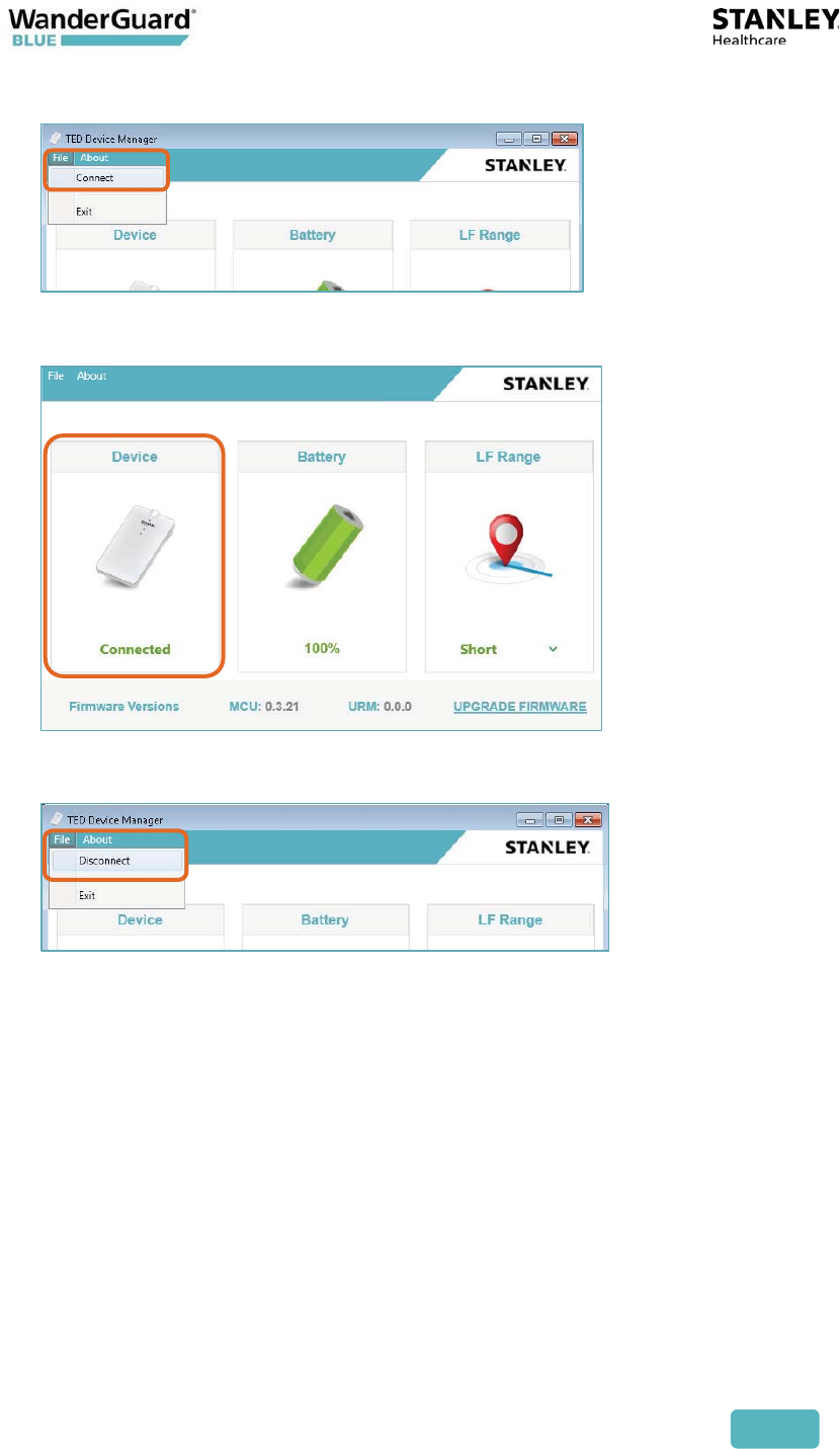
3. From the menu bar, click File and select Connect.
4. Connected is displayed when the device is connected:
5. To disconnect, click File and select Disconnect.
User and Deployment Guide
77
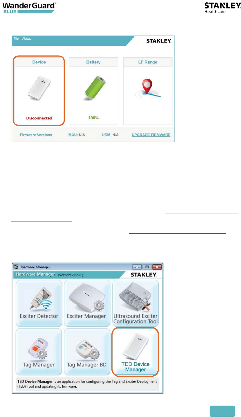
6. If the device is disconnected, Disconnected is displayed.
Viewing and Updating the Detector’s Firmware
The Detector’s current firmware can be viewed and easily updated using the
TED Device Manager.
To view and update firmware using the TED Device Manager:
1. Make sure the Detector is connected to the PC. See Connecting the Detector
Using the USB Cable.
2. Establish a connection to Detector. See Establishing A Connection to the
Detector.
3. From the Hardware Manager application, click TED Device Manager.
User and Deployment Guide
78
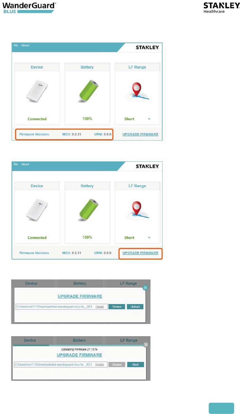
4. The Detector’s current firmware version appears at the bottom of the TED
Device Manager window.
5. To update the Detector’s firmware, click UPGRADE FIRMWARE.
6. Click Browse to navigate to the latest firmware version, and click Upload.
7. The firmware begins to upload to the WanderGuard BLUE detector.

User and Deployment Guide
79
8. When the upload is successfully completed, the system displays a message:
9. Disconnect the Detector from the USB cable and then reconnect it.
10. Open the Hardware Manager, and verify that the Detector’s firmware has
been updated by checking the firmware version.
Cleaning the Detector
Only use alcohol-based wipes to clean the device.

User and Deployment Guide
80
WanderGuard BLUE Detector Specifications
Product Specifications
Model SKU (USA): WGB-DET-1000-NA
SKU (non-USA): WGB-DET-1000-NonNA
Delivered with power charger and micro-USB cable (1
meter)
Performance Able to detect and configure up to 80 Tags
simultaneously
LF & BLE
- LF
- BLE
Short: 0.50 meters (1.65 feet)
Compliant with Bluetooth V4.1 (Bluetooth Smart)
Physical and
Mechanical
Dimensions: 120 mm x 68 mm x 20 mm
(4.72 in x 2.67 in x 0.78 in)
Weight: 120 g (4.23 oz.)
Environmental Operating Temperature: 0°C to 50°C (32°F to 122°F)
Humidity: 0% to 95% RH non-condensing
Ingress Protection Rating: IP-30
Electrical Micro-USB Port
4.2 V Li-Ion rechargeable battery
Radio Wi-Fi 802.11 (2.4 GHz); b/g/n compliant
Bluetooth V4. 1 (2.4 GHz) (Bluetooth Smart)
Low Frequency receiver (LF) 125 kHz
Transmission power: Up to +19 dBm (~81 mW)
Audio Buzzer: Volume level 80 dBA at 0.1 meters
Certifications Radio:
FCC Part 15, ETSI 300-328, 300-330, 301-489, RSS 210
(Canada), IEC 6100 / EN 60601
Safety:
CE EN 60950, cTUVus UL 60950, IEC 60601
Accessories Hardware Manager Application
SKU: HWM-1000
User and Deployment Guide
81
8
WanderGuard BLUE Manager
WanderGuard BLUE Manager is a STANLEY Healthcare mobile application
installed on an Asus ZenPad 8.0 (Z380M) tablet and supplied by STANLEY
Healthcare as an integral component of the WanderGuard BLUE Wander
Management Solution. The main function of the WanderGuard BLUE Manager
is to enable Controller configuration by downloading /uploading configurations
from/to the Controller and displaying the status of Tags and Controller(s).
Note
To modify a Controller configuration, the WanderGuard BLUE Manager
downloads the configuration from the Controller. The configuration
settings can be modified within WanderGuard BLUE Manager and then
uploaded to the Controller.
WanderGuard BLUE Manager:
x Runs on an off-the-shelf Asus Tablet
x Supports scanning for Tags and Controllers
x Displays status of Tags and Controllers
x Enables configuration of Controller’s Settings
x Enables configuration of the user credential information on the Controller
The Tablet supplied by STANLEY Healthcare is an 8-inch Asus ZenPad Z380M
Tablet with 2 GB RAM and 16 GB storage. It comes pre-installed with STANLEY
Healthcare's WanderGuard BLUE Manager, Google Sheets and a remote control
(TeamViewer) application to enable remote technical support by STANLEY
Healthcare.
Best Practice: Using any Tablet or software other than that supplied
by STANLEY Healthcare automatically voids any warranty that you may
have received from STANLEY Healthcare and absolves STANLEY
Healthcare of any damage that may be caused to your systems as a
result of its use.

User and Deployment Guide
82
Getting Started with Your Tablet
STANLEY Healthcare supplies the Tablet with the WanderGuard BLUE Manager
mobile application already installed. The following Tablet settings are already
enabled:
x Location services
x File access
x Bluetooth®
Note
If any of these services are not enabled, enable them before proceeding.
In addition, other dedicated applications are pre-installed by STANLEY
Healthcare to enable viewing CSV or other text files for troubleshooting and
management purposes.
Finally, TeamViewer is also installed to enable sharing the tablet screen and
remote control support from STANLEY Healthcare.
If remote control is supported, you have to perform the following on site:
x To be able to use the TeamViewer, port 5938 outgoing must be available
at your customer site. IT at the customer site must make this setting.
x Connect to the network via Wi-Fi.
For troubleshooting the tablet installation, see the tablet Troubleshooting
section in this User Guide.
If you need any help getting started with your Asus ZenPad Tablet, consult your
ZenPad user guide or download it here.
User and Deployment Guide
83
Launch WanderGuard BLUE Manager and Log in
To run WanderGuard BLUE Manager:
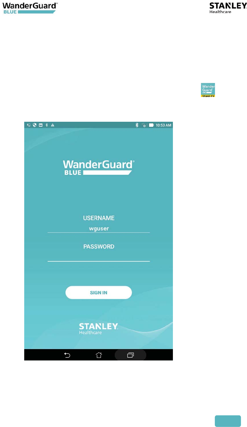
1. Swipe up to unlock the Tablet's screen, and on the Tablet's main screen
locate the WanderGuard BLUE Manager icon.
2. Click WanderGuard BLUE Manager to run the application .
3. The WanderGuard BLUE splash screen briefly appears. Then, the login
window opens:
4. The user name "wguser" needs to be entered.
5. On the screen, click PASSWORD.
6. Using the keyboard that opens, fill in the password: WG2017 (use upper
case letters only).
7. Click Done on the keyboard.
User and Deployment Guide
84
8. Click SIGN IN.
Note
There is no "remember me" option for signing in. You will have to enter
this password each time you log in.
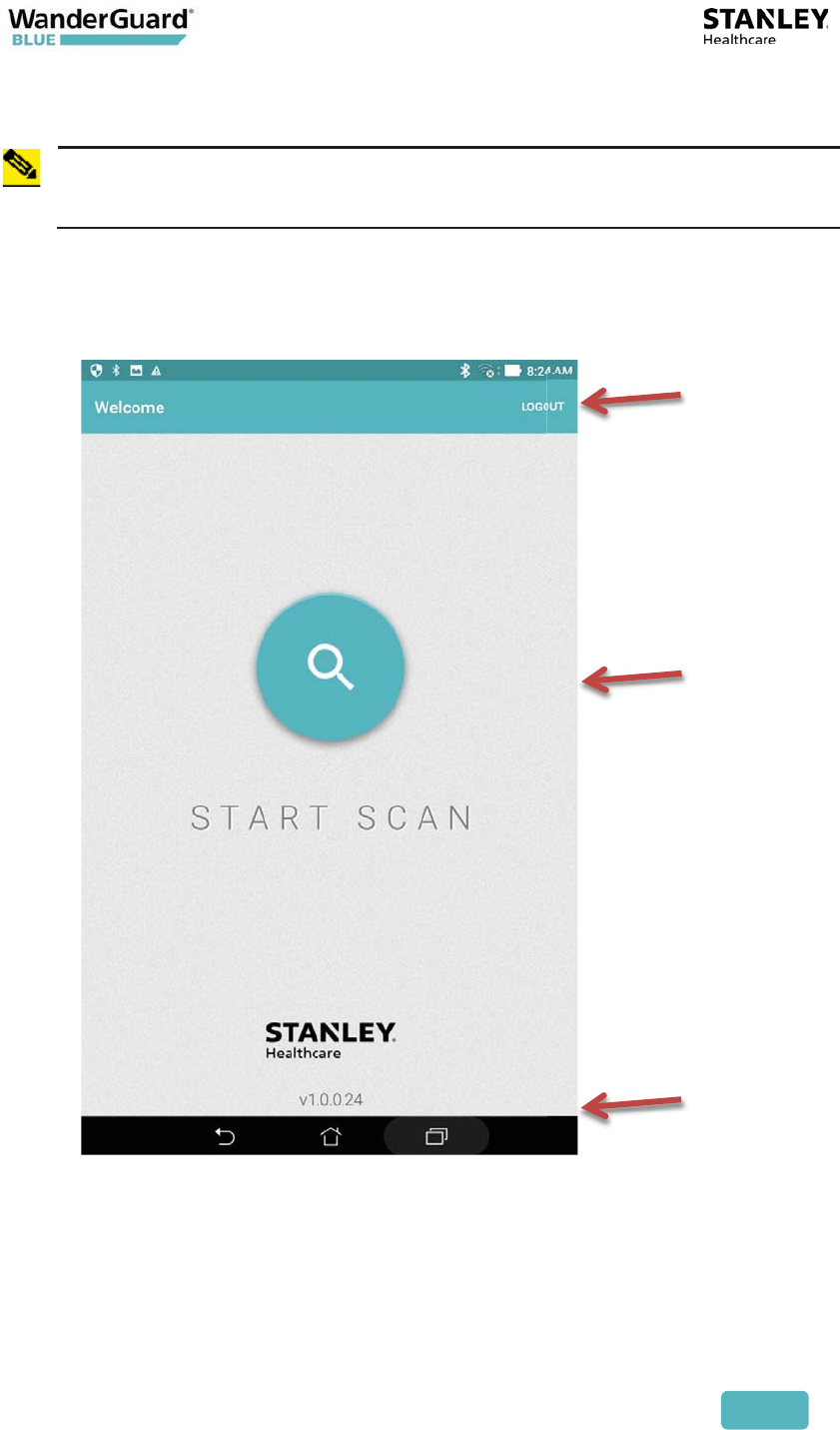
9. The Tablet Mobile App Welcome screen appears. The Welcome screen
has a Logout button on the top-right and a large Start Scan button in
the center. The current WanderGuard BLUE software version number is
displayed on the Welcome screen's bottom-middle.
User and Deployment Guide
85
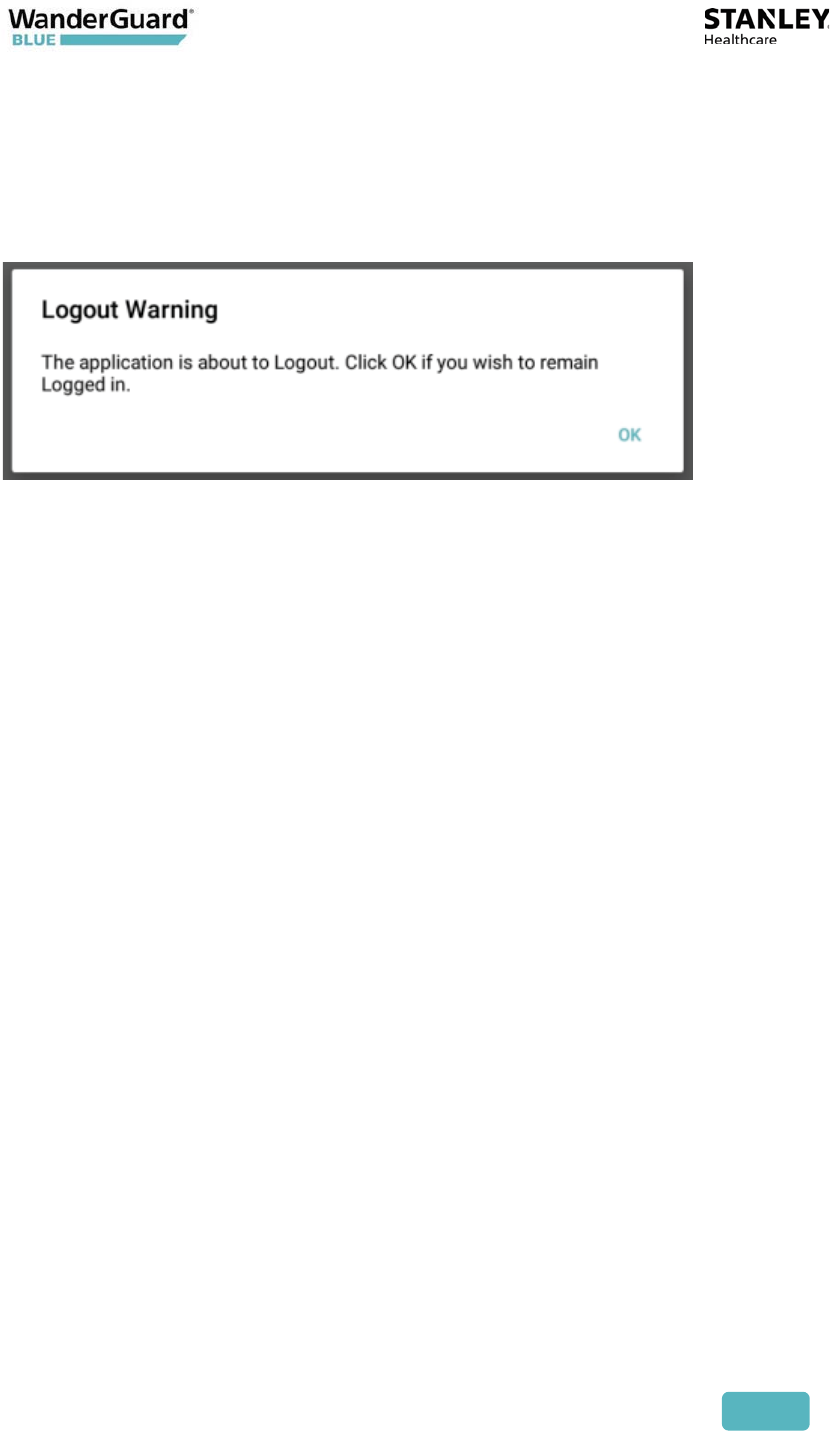
Automatic Logout
The WanderGuard BLUE Manager is programmed to issue a Logout Warning
message after 57 minutes of no activity.
After 57 minutes, the following message appears:
If OK is not pressed, the app automatically logs out and returns you to the Login
screen.
If WanderGuard BLUE Manager is connected to a Controller, it first disconnects
from the Controller.
To enter the WanderGuard BLUE Manager again, log in as required.
If you press OK within three minutes of the Logout Warning message, the
Automatic Log Out time is reset (you have another 57 minutes of no activity
until the Logout Warning message reappears).
Scanning for Controllers and Tags
How It Works
Scanning with the WanderGuard BLUE Manager allows identifying Controllers
and Tags in the vicinity of the Tablet.
For Tags to be identified, a WanderGuard BLUE Detector needs to be
transmitting in the vicinity of the Tags.
The WanderGuard BLUE Detector emits an LF signal. When it is received by the
Tag, the Tag sends a BLE response. The Tag continues to transmit as long as it
continues to receive LF signals from the Detector. The Tag BLE message is also
received by the WanderGuard BLUE Manager when it runs a scan (the
WanderGuard BLUE Manager does not communicate directly with the Detector).
The Controller transmits BLE messages even if there is no Detector in the
vicinity. The Controller uses its BLE transceiver to send BLE messages with
Controller information every three seconds. The Controller's BLE message is read
by the WanderGuard BLUE Manager when it performs a scan.
User and Deployment Guide
86
WanderGuard BLUE Tags and Controllers are identified by WanderGuard BLUE
Manager and displayed in its Scan Results window.
Performing a Scan for Controllers and Tags
To scan for Controllers and Tags:
1. On the Home screen, press the Scan. A scan progress icon appears. The
scan runs for about 20 seconds.
2. You can stop/start a scan by pressing the Start/Stop Scan toggle
button.
3. A Scan Results window opens and detected Tags and Controllers are
displayed.

User and Deployment Guide
87
Note
x WanderGuard BLUE Manager scans for Controllers and Tags in its
vicinity and displays their properties in the Scan Results window.
x Tag activation is done ONLY by the Detector.
Viewing Scan Results
In the Scan Results window, you can view the following scan results:
x Controllers
x Tags
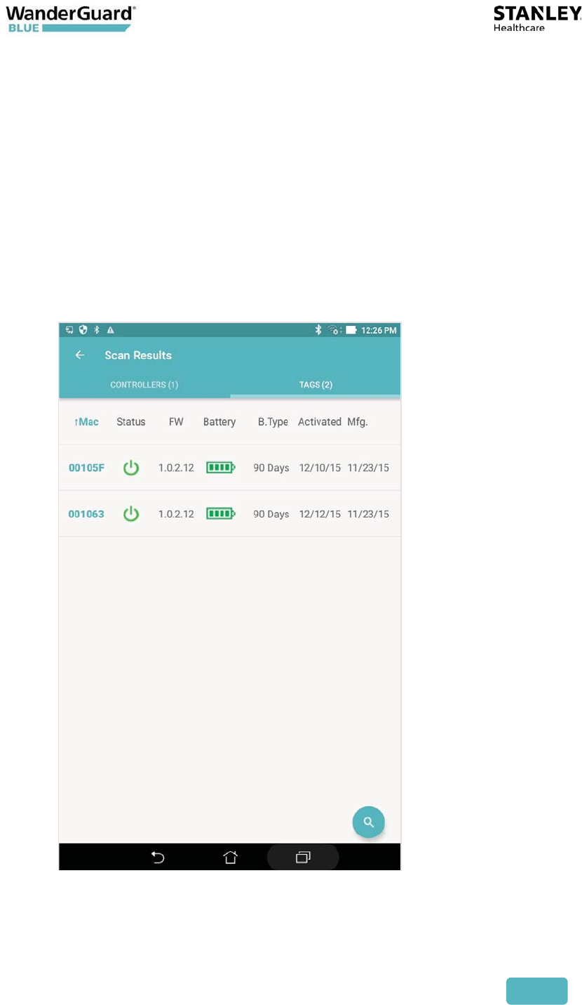
Tag Scan Results
Scan results are displayed in the Scan Results window. Click Tags to open the
Tags tab.
The number of identified Tags is displayed in parenthesis adjacent to the Tags
caption.
Tag details are displayed in a table with the following columns (see following
screen):
x Tag ID – the Tag's ID is the last six digits of its MAC address. The Tag ID is
printed on the side of the Tag.
x Status – Dormant or Active; firmware version
x Firmware version
x Battery - Good or Low
x Battery Type - 90 days or 3 years
x Activation date – date of Tag activation
x Manufacturing date – Tag manufacturing date
Sorting each column (ascending/descending order) can be done by clicking the
column title.
User and Deployment Guide
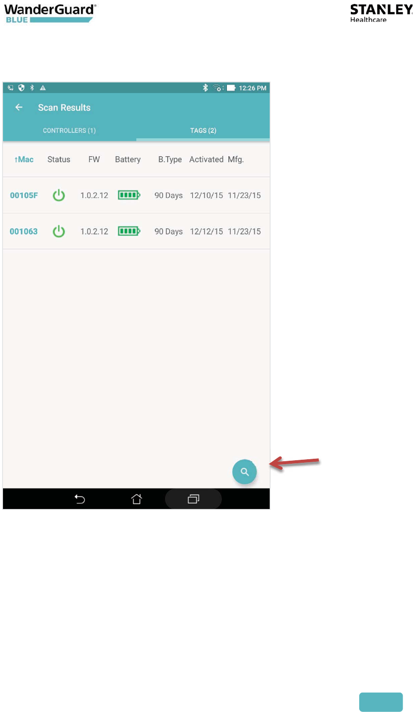
88
A rescan can be done by clicking the Scan button on the bottom right of the
Scan Results screen.
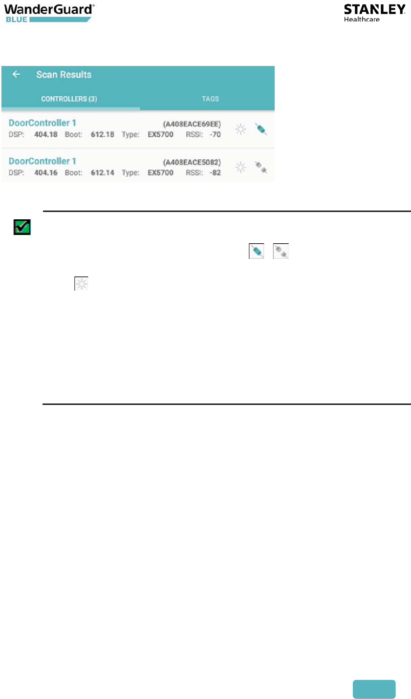
Controller Scan Results
After a scan is run from the Welcome screen, the Scan Results screen opens with
Controllers displayed by default. The number of identified Controllers is
displayed in parentheses adjacent to the Controllers caption. If you are in the
Tags tab, you can view Controller Results by clicking Controllers to open the
Controllers tab.
Controller details are displayed in two-line rows: the first row is the Door
Controller name and MAC address (in parentheses). The second line includes the
DSP firmware version, Boot firmware version, Controller type, and RSSI level of
the received BLE from the Controller.
User and Deployment Guide
89
The list is sorted by RSSI level.
Best Practice: WanderGuard BLUE Manager can connect to only one
Controller at a time.
Click the Connect/Disconnect toggle ( / )to connect/disconnect
from a Controller.
Click to establish a BLE connection AND have the Controller blink
for five seconds.
Controller blinking is useful to confirm that you are connected to the
Controller to which you want to be connected (if there is more than
one Controller in the vicinity).
If you try to connect WanderGuard BLUE Manager to a new Controller
while the application is still connected to another Controller,
WanderGuard BLUE Manager will first disconnect from the current
Controller and only then connect to the new Controller.
In order to view the Controller to review its configuration, tap the Controller
line in WanderGuard BLUE Manager. The Controller Settings page opens after
WanderGuard BLUE Manager has made a successful BLE connection to the
Controller.
Controller Configuration
WanderGuard BLUE Manager allows you to configure the Controller after
connecting to it.
To configure the Controller:
x Obtain the Controller's configuration by performing a scan, and display it in
the WanderGuard BLUE Manager (open the Controller tab)
x Modify the desired parameters in WanderGuard BLUE Manager
x Save (Apply) the modified configuration from the WanderGuard BLUE
Manager to the Controller
User and Deployment Guide
90
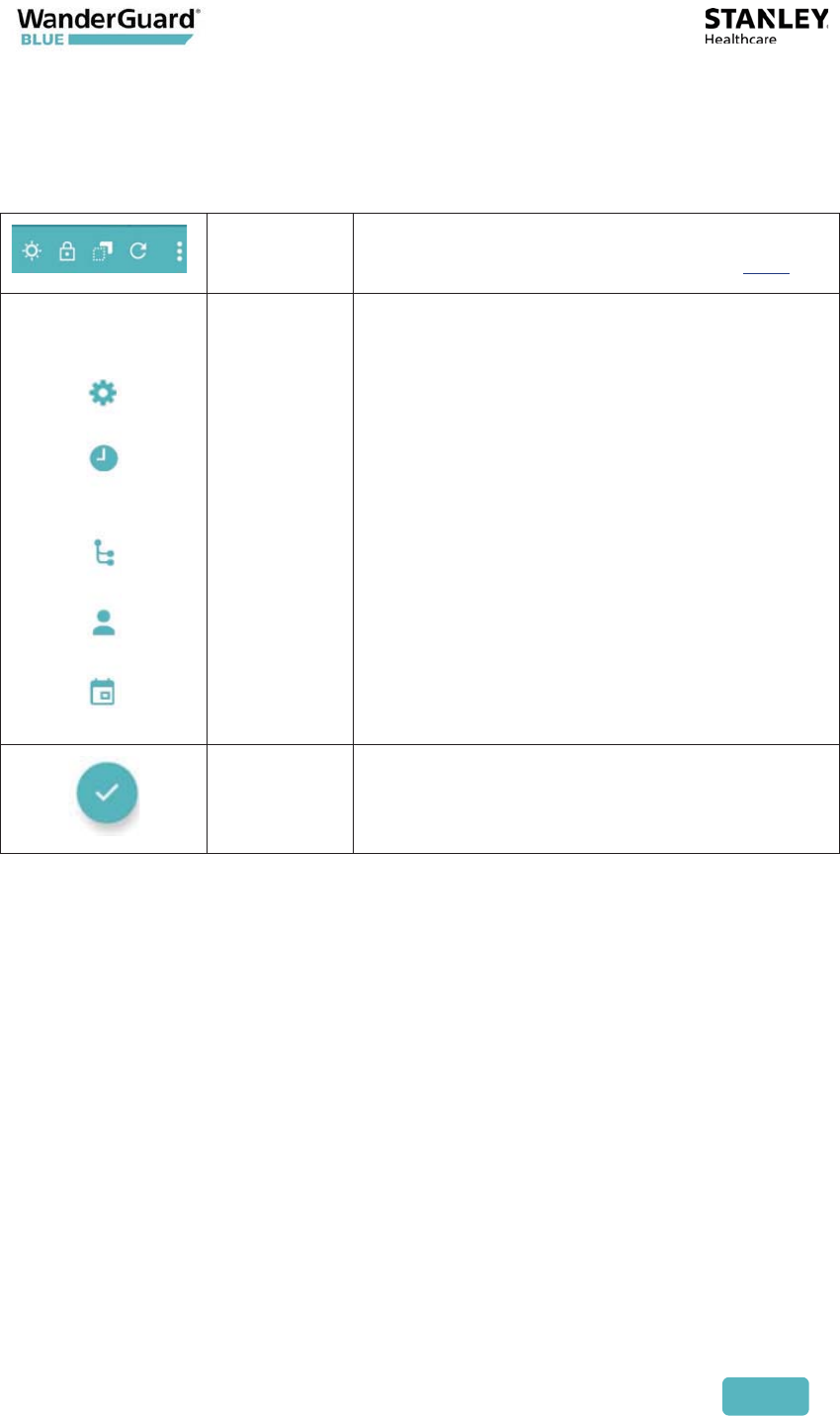
Controller Pages User Interface
The User Interface (UI) has the following fixed elements:
Toolbar Horizontal toolbar across the top of the page
that provides extra functionality (see here)
Navigation
bar
Vertical left-hand bar to select one of the
configuration pages:
x Settings – for setting the Controller
properties
x Clock – for setting the Controller date,
time, world Time Zone and Daylight
Savings Time (DST).
x Outputs – Programmable Output
activation
x Users – list of users who have the access
code to the monitored door(s)
x Schedule – Day/Night mode schedule for
each day
Apply
button
Validates and applies to the Controller the
configuration settings of the page that the
user is at
User and Deployment Guide
91
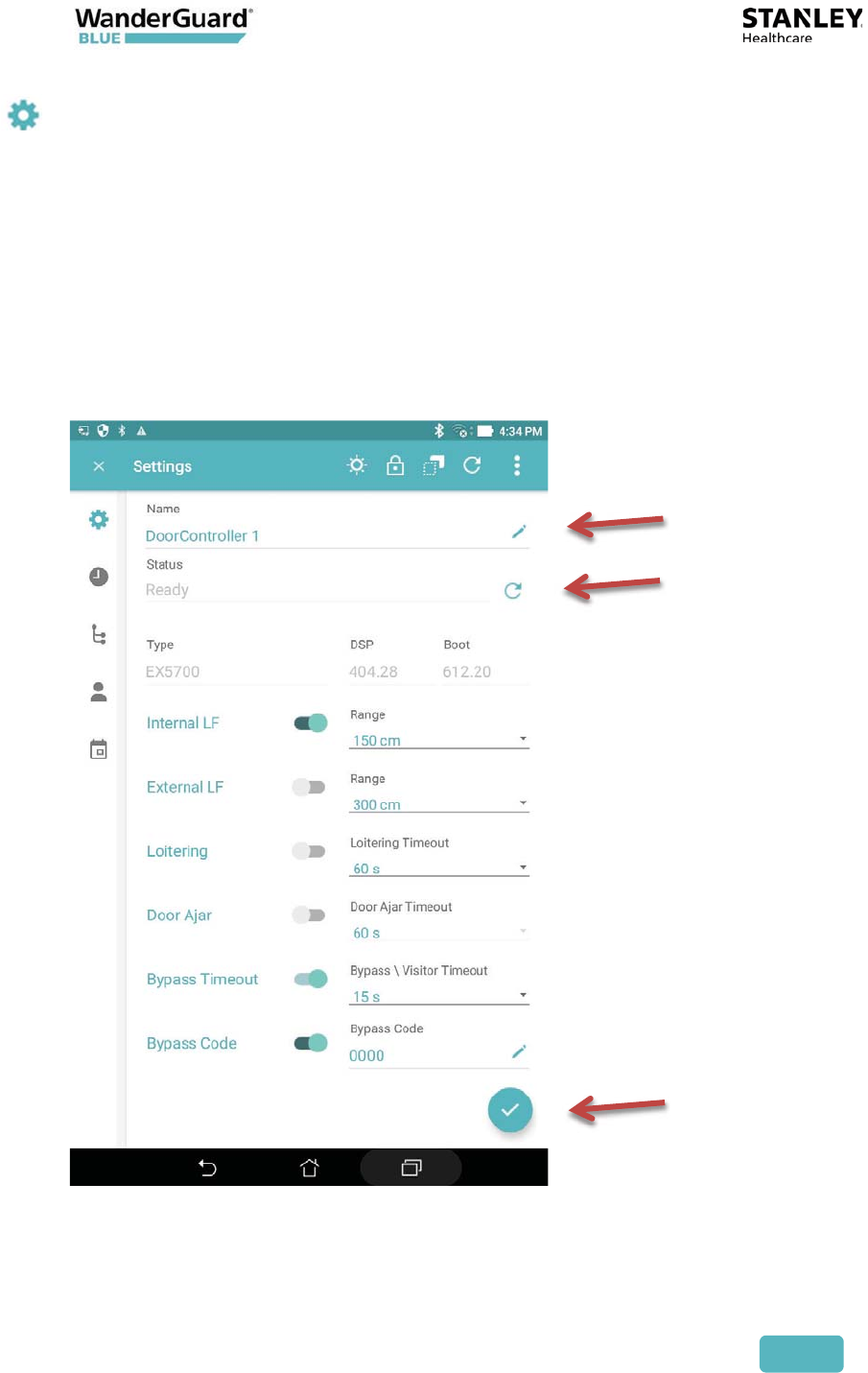
Settings
The Settings page is the default page when the Controller tab Configuration
page is opened. Scrolling down the page allows viewing all the Controller’s
settings (not all settings are visible at one time in a Tablet window).
The Controller Status, which is displayed in the Settings page, is refreshed
automatically once a minute. The Status can be updated immediately by
pressing the Refresh icon on the Status row.
If changes are made to Controller settings, these changes can be saved to the
Controller from the WanderGuard BLUE Manager by pressing the Apply
button.
Rename
Refresh
Apply
User and Deployment Guide
92
Parameter Definition
Controller
Name
Length is limited to 16 characters.
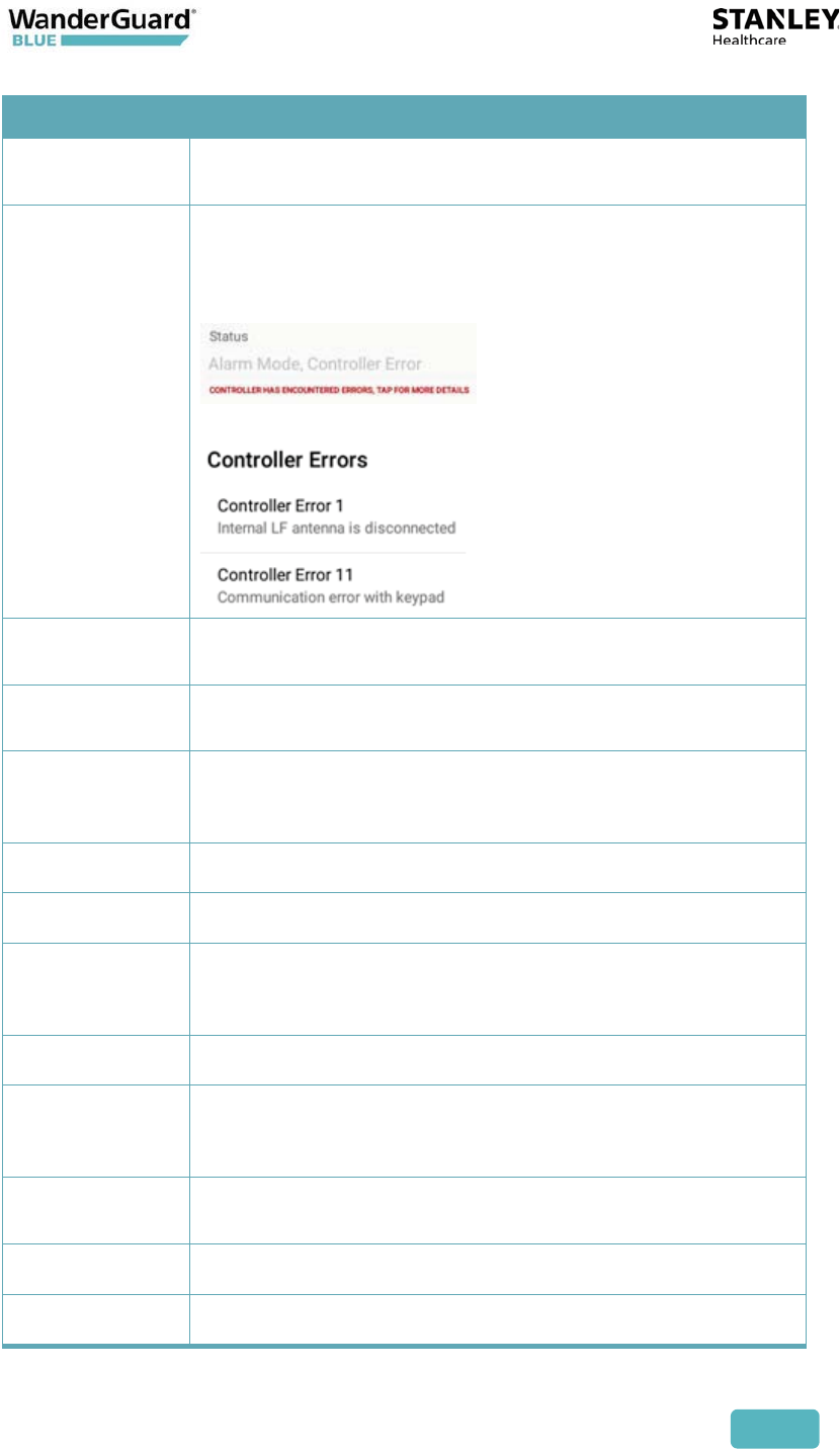
Status Displays Controller status. Typically, the current
Controller mode is displayed (Override, Alarm, Bypass,
Visitor, Night, Ready). Error messages are displayed if
there are errors.
You can tap the message to obtain more detail:
Type / DSP
/Boot
Type of Controller plus DSP and boot firmware version
Internal LF Normally ON. Can be set to up to 650 cm. External LF can
be enabled when internal LF is disabled.
External LF Normally OFF. Can be set to up to 300 cm. Used only
when an accessory Exciter is attached for greater
coverage.
Loitering Timeout can be set.
Door Ajar Timeout can be set.
Bypass
Timeout
Cannot be disabled. Bypass and Visitor timeout range is
5-300 seconds (5 seconds resolution). The timeout range
applies to both Bypass and Visitor. Default is 5 seconds.
Bypass Code Default can be changed by the user.
Visitor Code Default can be changed by the user. The Visitor Code
allows access but the system remains active against
resident wander ("tailgating").
Alarm Reset
Code
Cannot be disabled
Relay 1 Status Normally inactive
Relay 2 Status Normally inactive
User and Deployment Guide
93
List of Possible Errors from the Controller:
x Communication error with Keypad
x FW upgrade failure of UD BLE module
x FW upgrade failure of BD BLE module
x UART failure with UD BLE module
x UART failure with BD BLE module
x Relay2 physical activation failed
x Relay1 physical activation failed
x External LF error detected
x Internal LF error detected
x External LF antenna is disconnected
x Internal LF antenna is disconnected
x BLE monitoring error
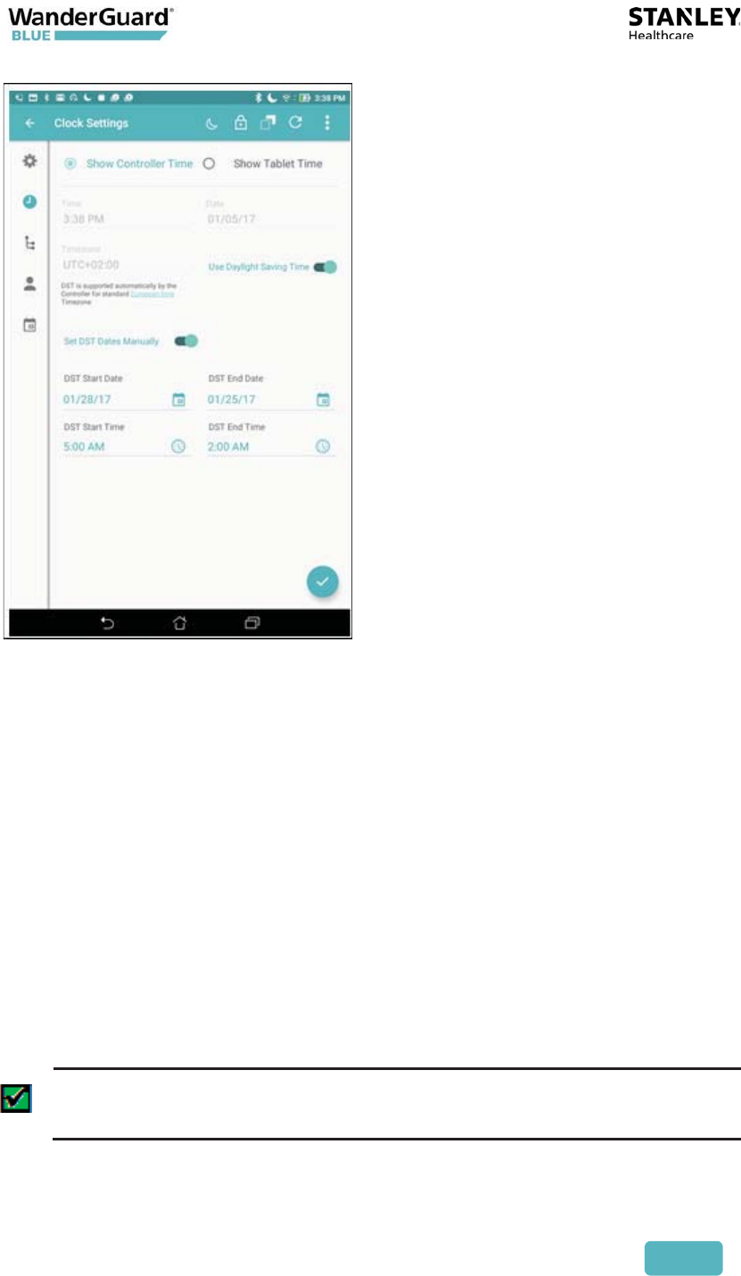
Clock Settings
Use the Clock Settings page to update the time, date, Time Zone and Daylight
Savings Time (DST). Clock settings are used by the Controller to enforce the
Day/Night mode schedule.
The time (shown on the Clock Settings page) is updated once per minute.
Choose the device by selecting Choose Controller Time or Choose Tablet Time.
The default view on the WanderGuard BLUE Manager is Controller Time. Time is
shown by time of day, date and Time Zone.
In the Clock Settings page, you can do the following:
x View Controller Time
x View Tablet Time
x Apply the Tablet Time, Date and Time Zone to the Controller
x View and change Daylight Savings Time settings for the Controller
Best Practice: Initial setup requires setting the time of both the
Controller and Tablet.
In addition to initial setup of the Controller, it is recommended to adjust
the Controller clock once every six months.
User and Deployment Guide
94
To open the Clock settings page:
1. Click Scan in WanderGuard BLUE Manager to generate a list of
Controllers in your range.
1. Click Connect to connect to the Controller of your choice.
2. The Settings page opens by default for the Controller that you chose.
3. Click Clock Settings in the vertical navigation bar to open the Clock
Settings page.
4. Verify that your device of choice is selected (Controller or Tablet).
To change Controller's date and time:
1. Choose the Show Tablet Time radio button.
2. Verify that the Tablet Time, Date, and Time Zone are accurate.
3. Set the Daylight Saving Time parameter.
4. Click Apply to upload Tablet time to the Controller.
5. A message appears that "Clock configuration applied successfully."
6. This date and time are then also displayed in the Indoor Keypad.
Best Practice: All the Clock Settings (Time, Date and Time Zone) in the
Tablet are uploaded to the Controller not just the Tablet time.
User and Deployment Guide
95
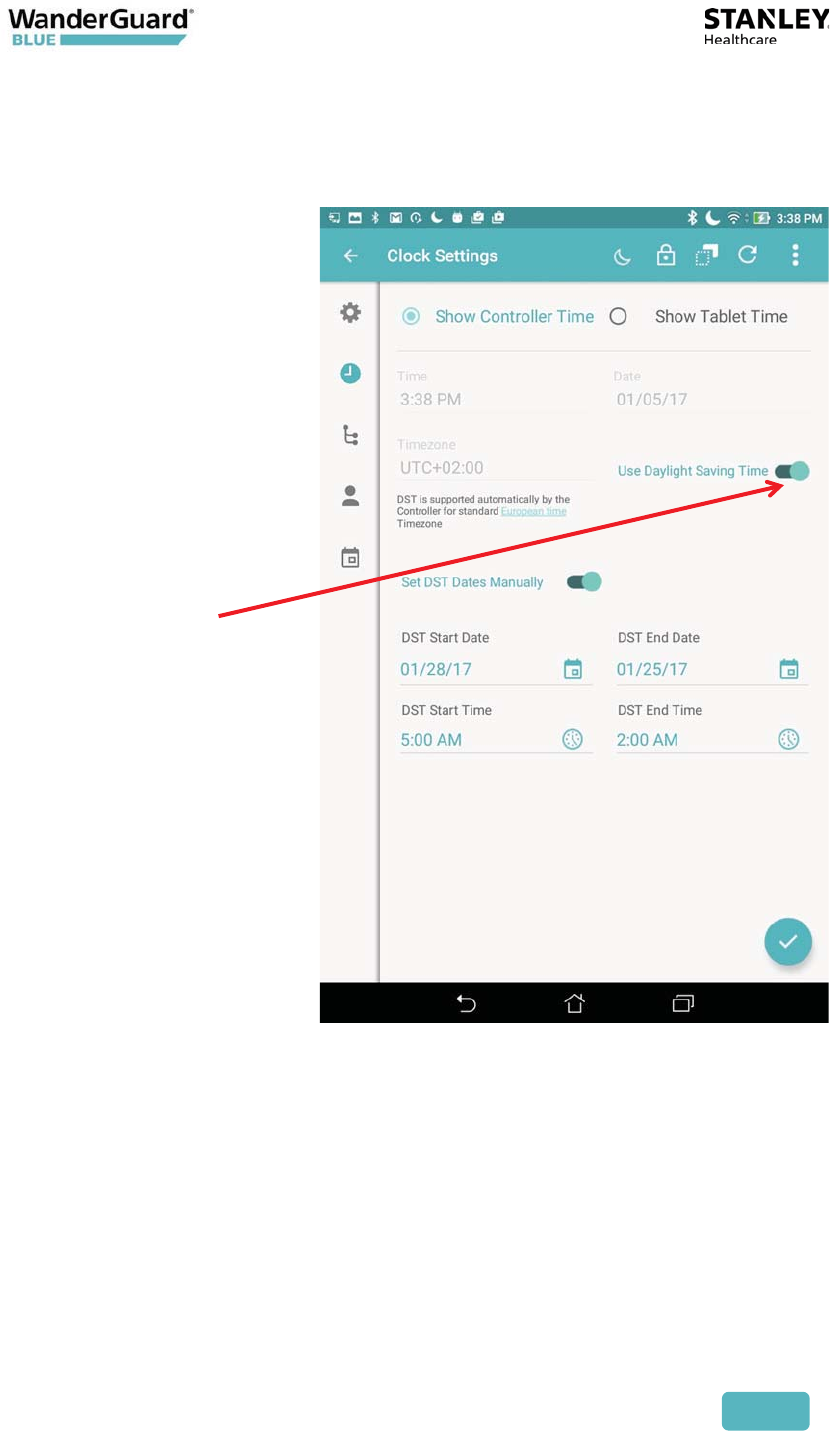
Daylight Savings Time:
Daylight Savings Time (DST) is enabled by default. It can be disabled if the world
Time Zone does not support DST.
There are three different possible configurations of Daylight Saving Time:
"Automatic" DST
For US/Canada/Europe world Time Zones, the Controller moves to Daylight
Saving Time and back automatically.
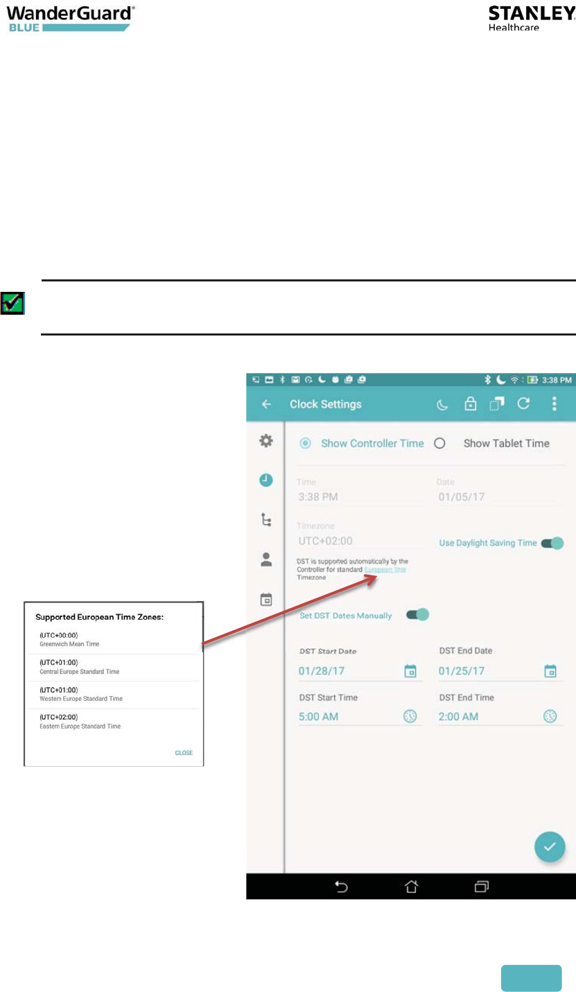
The Time Zones are:
x (UTC+00:00) Greenwich Mean Time
x (UTC+01:00) Central Europe Standard Time
x (UTC+01:00) Western Europe Standard Time
Select DST
User and Deployment Guide
96
x (UTC+02:00) Eastern Europe Standard Time
x (UTC-04:00) Atlantic Time (Canada)
x (UTC-05:00) Eastern Time (US and Canada)
x (UTC-06:00) Central Time (US and Canada)
x (UTC-07:00) Mountain Time (US and Canada)
x (UTC-08:00) Pacific Time (US and Canada)
x (UTC-09:00) Alaska
WanderGuard BLUE Manager indicates that DST is automatically supported
when these Time Zones are used:
Best Practice: To use automatic DST support, your Tablet time has to be
set to a US/Canada/Europe world Time Zone.
User and Deployment Guide
97
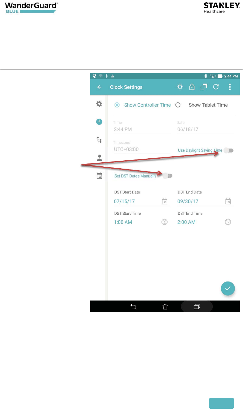
DST Disabled
If the world Time Zone does not support Daylight Saving Time (for example,
Hawaii), disable the "Use Daylight Saving Time" setting. In this case, "Set DST
Dates Manually" is also disabled.
DST functionality
disabled
User and Deployment Guide
98
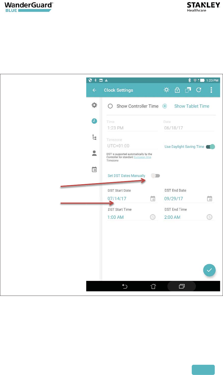
DST Enabled with Manual Setting of DST Times
In this scenario, you manually set the DST start and end dates. Manual settings
override any "automatic" settings.
1. Enable DST ("Use Daylight Saving Time").
2. Enable "Set DST Manually."
3. Set the Start and End date/time of the DST.
Set DST Manually
Set Start/End
Date/Time
User and Deployment Guide
99
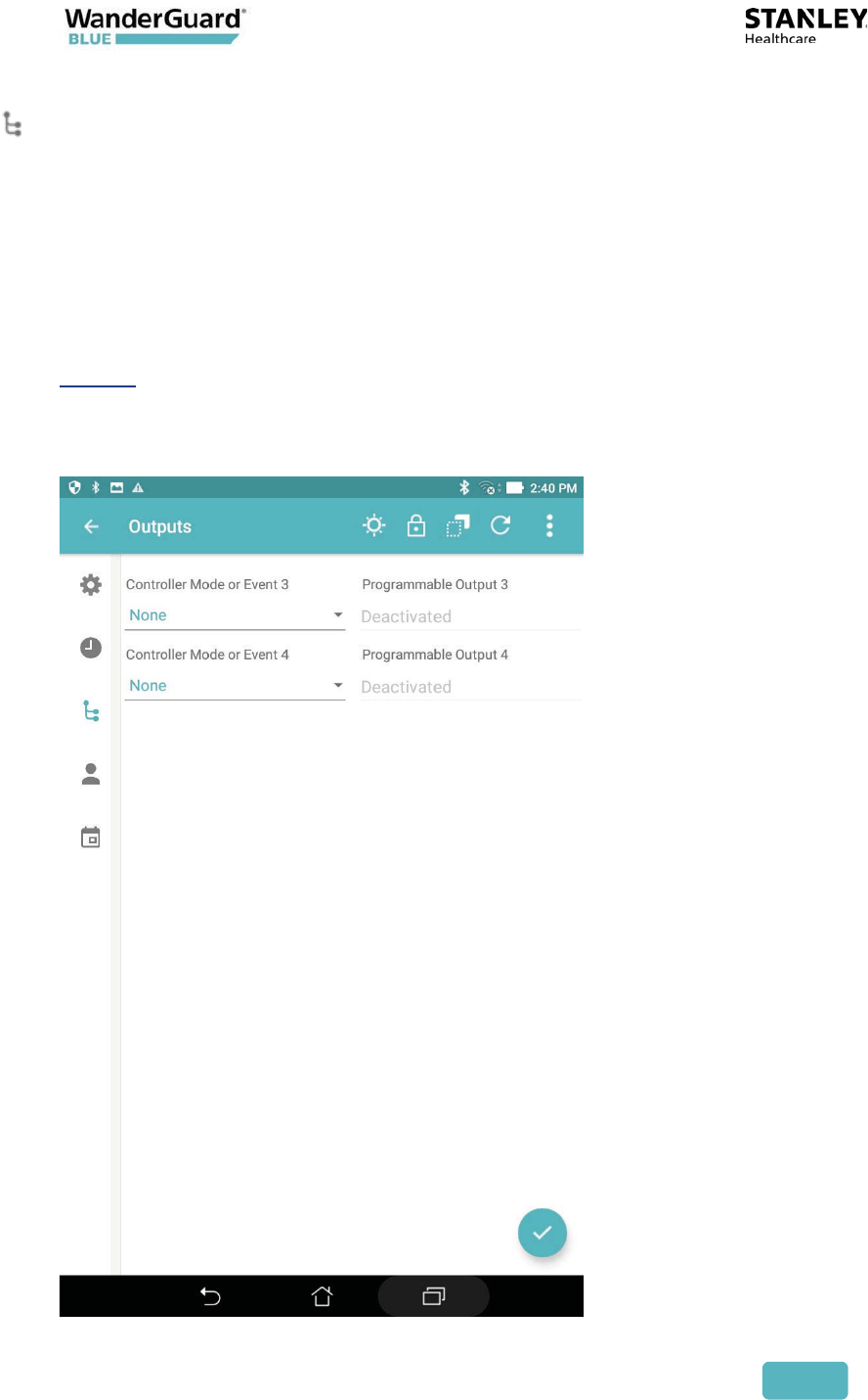
Outputs
The Controller has two programmable outputs – Outputs 3 and 4. These outputs
can be programmed to be activated when a Controller mode changes or event
occurs. When the event is cancelled or the Controller mode changes back to its
previous mode, the output is deactivated.
Outputs can be an alarm or bell, flashing light, etc., depending on the mode
and desired result.
The Controller’s terminal block has the following outputs (see the Controller
chapter in this Guide for more details):
x Controller's OUT3 – WanderGuard BLUE Manager's programmable Output 3
x Controller's OUT4 – WanderGuard BLUE Manager's programmable Output 4

User and Deployment Guide
100
The following output activation options can be set:
x None (disabled)
x Bypass mode
x Alarm mode
x Override mode
x Night mode
x Loitering (if LF and Loitering are enabled)
x Door Ajar (if Door Ajar is enabled)
x Visitor mode (if Visitor mode is enabled)
To activate a Programmable Output option:
1. Click Scan button in WanderGuard BLUE Manager to generate a list of
Controllers in your range.
2. Click Connect to connect to the Controller of your choice.
3. The Settings page opens by default for the Controller that you chose.
4. Click Outputs in the vertical navigation bar to open the Outputs page.
5. On the Outputs page, select your desired mode in the Controller Mode
or Event pull-down menu.
6. In Programmable Output 3, click the Activated/Deactivated toggle.
7. Repeat step 5 and 6 for Controller Mode or Event and Programmable
Output 4, as necessary.
8. Click Apply to save any changes to the current Controller.
User and Deployment Guide
101
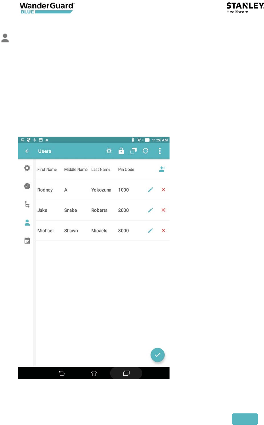
Users
Out of the box, the Controller has no configured users. Users can be added
(deleted and modified) in WanderGuard BLUE Manager. The parameters of a
user entity are as follows (all mandatory):
x First Name (up to 16 alpha-numeric characters including ‘-’ (dash), ‘ ‘ (space)
and ‘.’ (period)
x Middle Name (up to 16 char)
x Last Name (up to 16 char)
x PIN code (4 digits; must be unique)
The Controller supports up to 45 users in the Users List.
User and Deployment Guide
102
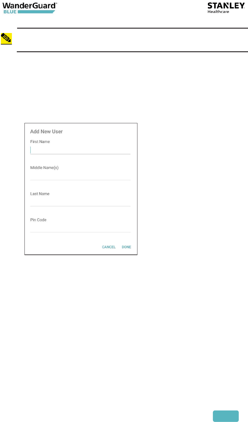
Note
The combination of names (first, middle, last) must be unique.
To Add a New User:
1. Click Scan in WanderGuard BLUE Manager to generate a list of
Controllers in your range.
2. Click Connect to connect to the Controller of your choice.
3. The Settings page opens by default for the Controller that you chose.
4. Click Users in the vertical navigation bar to open the Users page.
5. On the Users page, click the New User icon.
6. Fill in the name fields and the PIN code.
7. Click Done to finish or Cancel to disregard your work. Pressing Done
validates the new user or reports errors if the entered data is not
compliant.
8. Click Apply to save any changes to the current Controller.
User and Deployment Guide
103
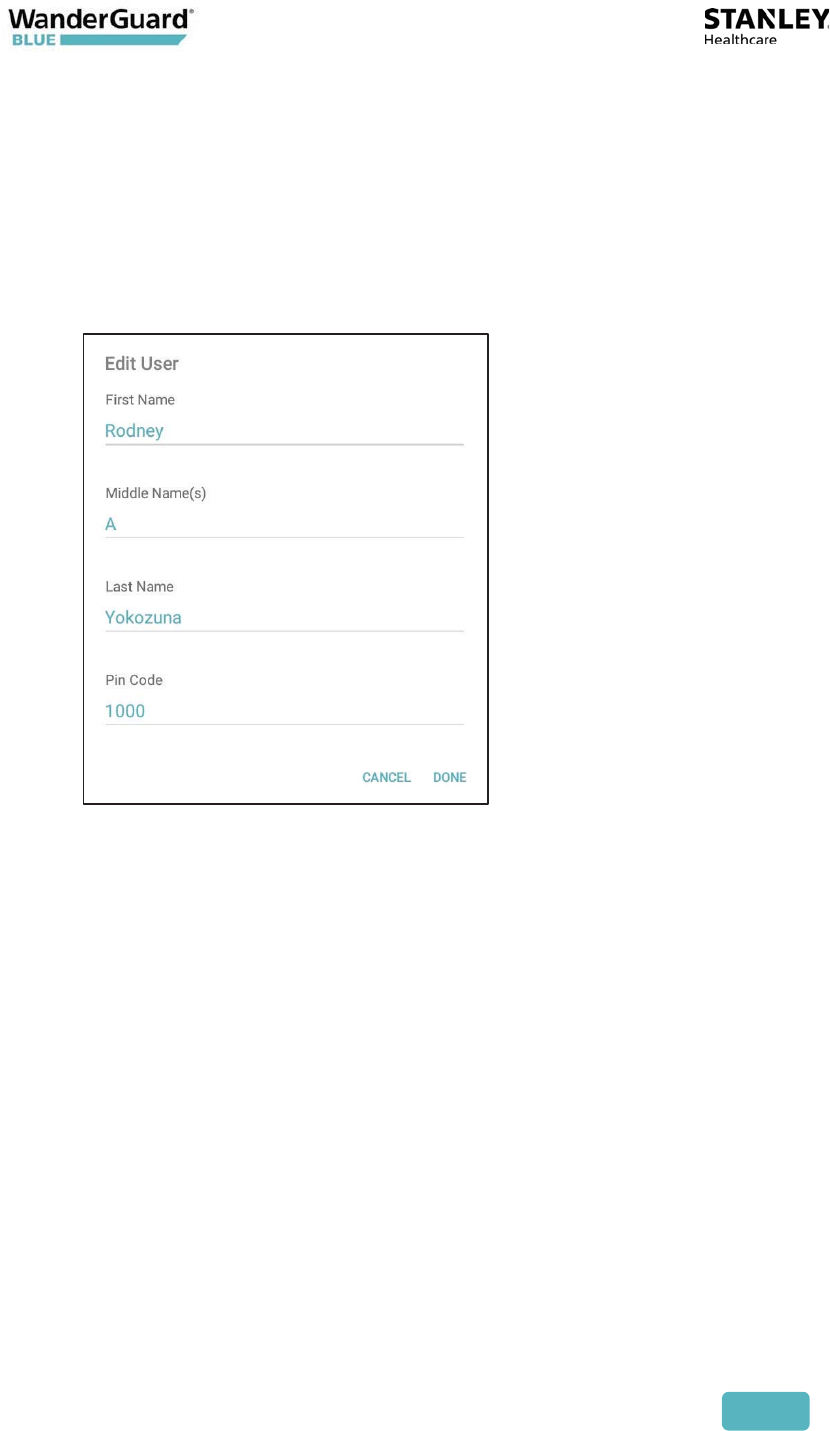
To Edit Users in the Controller:
1. Click Scan in WanderGuard BLUE Manager to generate a list of
Controllers in your range.
2. Click Connect to connect to the Controller of your choice.
3. The Settings page opens by default for the Controller that you chose.
4. Click Users in the vertical navigation bar to open the Users page.
5. On the Users page, tap to select your desired user from the list. Fill in the
name fields and the PIN code.
6. Click Done to finish or Cancel to disregard your work. Pressing Done
validates the modified user entry or reports errors if the entered data is
not compliant.
7. Click Apply to save any changes to the current Controller.
User and Deployment Guide
104
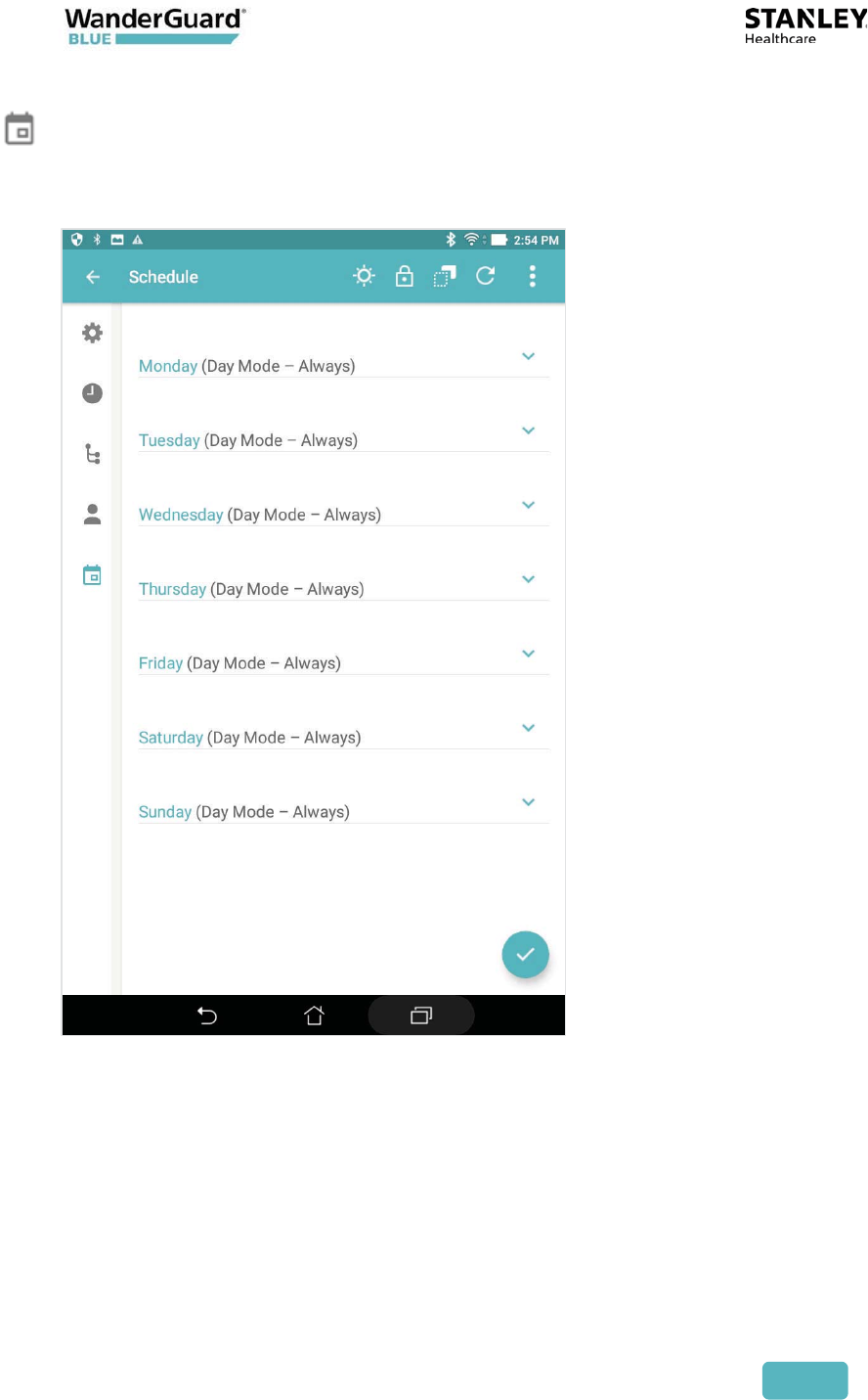
Schedule
The Day/Night Schedule page allows you to schedule day and night shifts for
each individual day of the week.
The following options exist:
x Day Mode - Always – the Controller is in Day mode all day
x Night Mode - Always – the Controller is in Night mode all day
x Custom Range – the Controller is in Day mode during specified hours
User and Deployment Guide
105
To Edit the Day/Night mode schedule in the Controller through the
Tablet Mobile App:
1. Click Scan in WanderGuard BLUE Manager to generate a list of
Controllers in your range.
2. Click Connect to connect to the Controller of your choice.
3. The Settings page opens by default for the Controller that you chose.
4. Click Schedule in the vertical navigation bar to open the Schedule page.
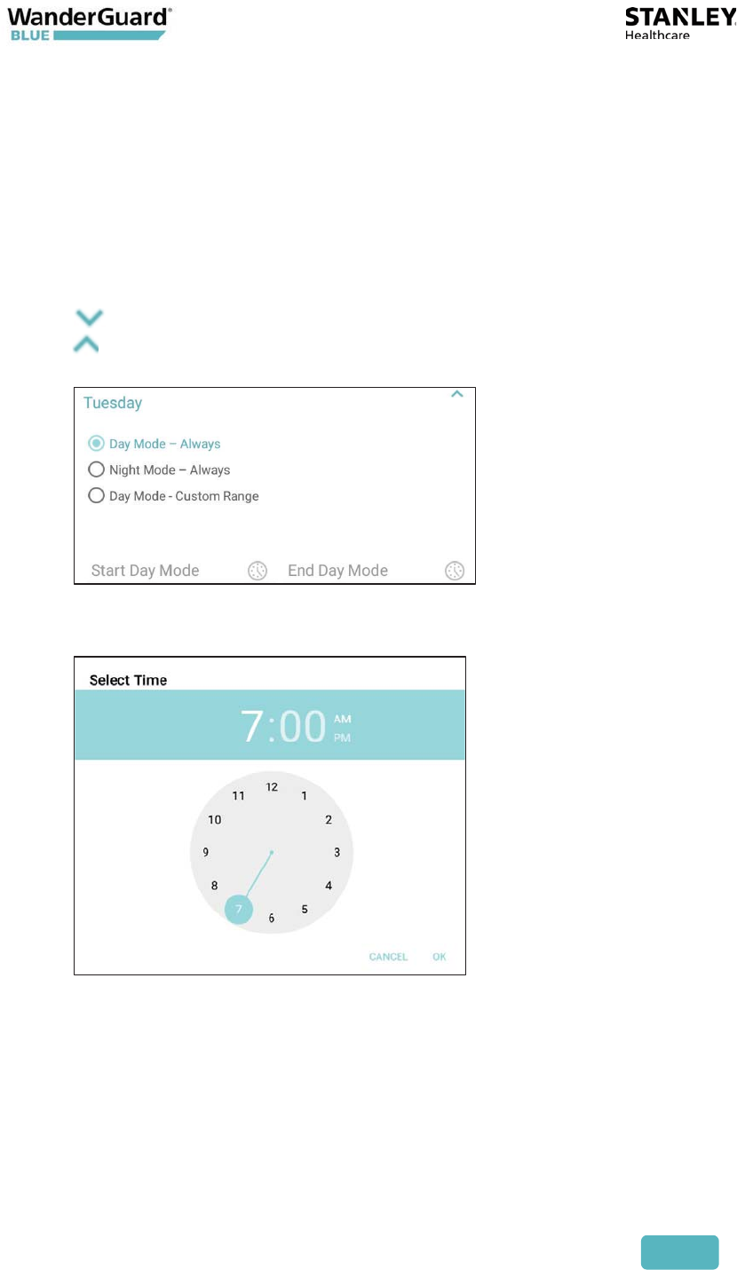
5. For each day in the Schedule page, the configuration options can be
expanded:
to expand the daily options
to compress the daily options
6. The following options window opens:
7. If Custom Range is chosen, the Start Day Mode time and End Day Mode
time can be selected:
8. Click Apply to save any changes to the current Controller.

User and Deployment Guide
106
Toolbar Actions
The following actions are available from the WanderGuard BLUE Manager
toolbar:
x Start/Stop Day/Night Mode
x Start/Stop Override Mode
x Copy/Paste Controller Configuration
x Refresh (Get Controller Properties)
x More – additional options
User and Deployment Guide
107
Start/Stop Day/Night Mode
This toggle switches between Day Mode and Night Mode.
Note
Day Mode is the default mode of the Controller.
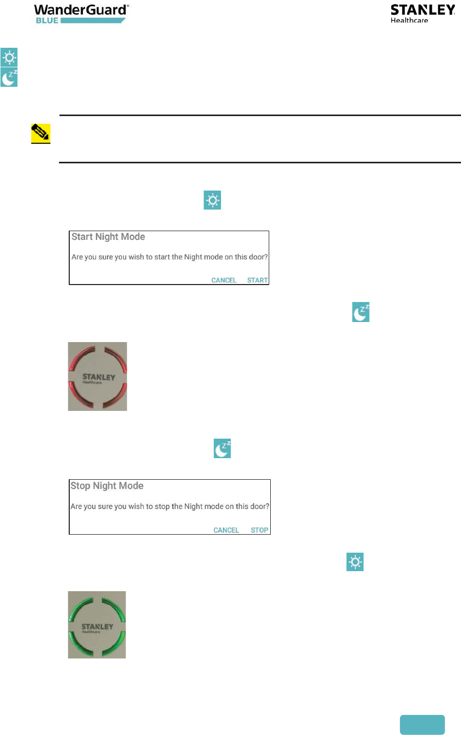
To toggle from Day to Night Mode:
1. Click the Day Mode icon .
2. A confirmation message appears:
3. Click Start to begin Night Mode.
4. The Day Mode icon switches to the Night Mode icon .
5. The color of the Controller LED switches to red.
To toggle from Night to Day Mode:
1. Click the Night Mode icon .
2. A confirmation message appears:
3. Click Stop to stop Night Mode.
4. The Night Mode icon switches to the Day Mode icon .
5. The color of the Controller LED switches to green.
User and Deployment Guide
108
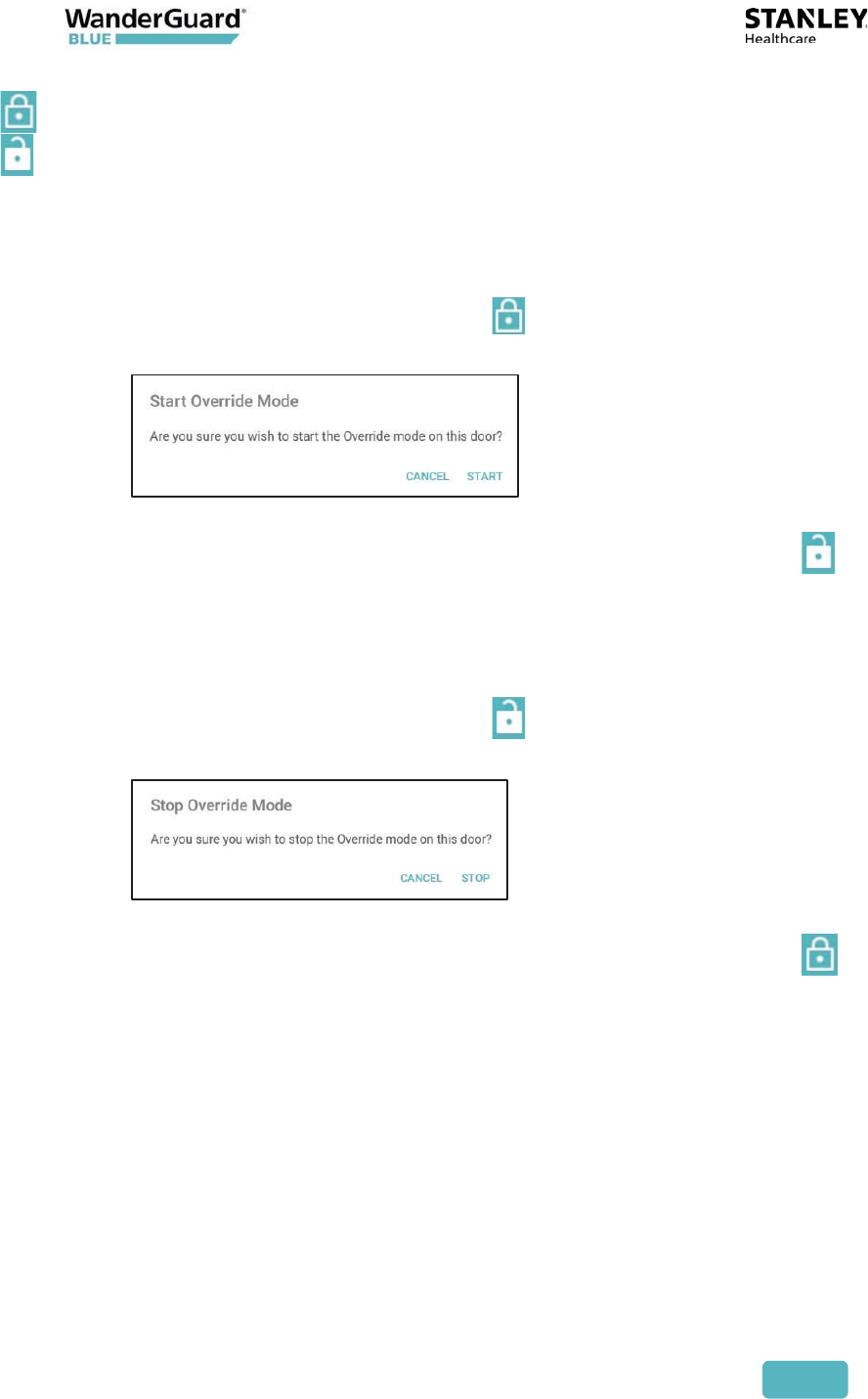
Start/Stop Override Mode
This toggle switches between Starting/Stopping Override Mode on the door
supervised by the Controller.
To toggle from non-Override Mode to Override Mode:
1. Click the non-Override Mode icon .
2. A confirmation message appears:
3. Click Start to begin Override Mode.
4. The non-Override Mode icon switches to the Override Mode icon ,
and the Controller LED continuously flashes Green.
To toggle from Override Mode to non-Override Mode:
1. Click the non-Override Mode icon .
2. A confirmation message appears:
3. Click Stop to stop Override Mode.
4. The non-Override Mode icon switches to the Override Mode icon ,
and the Controller LED returns to solid Green.
User and Deployment Guide
109
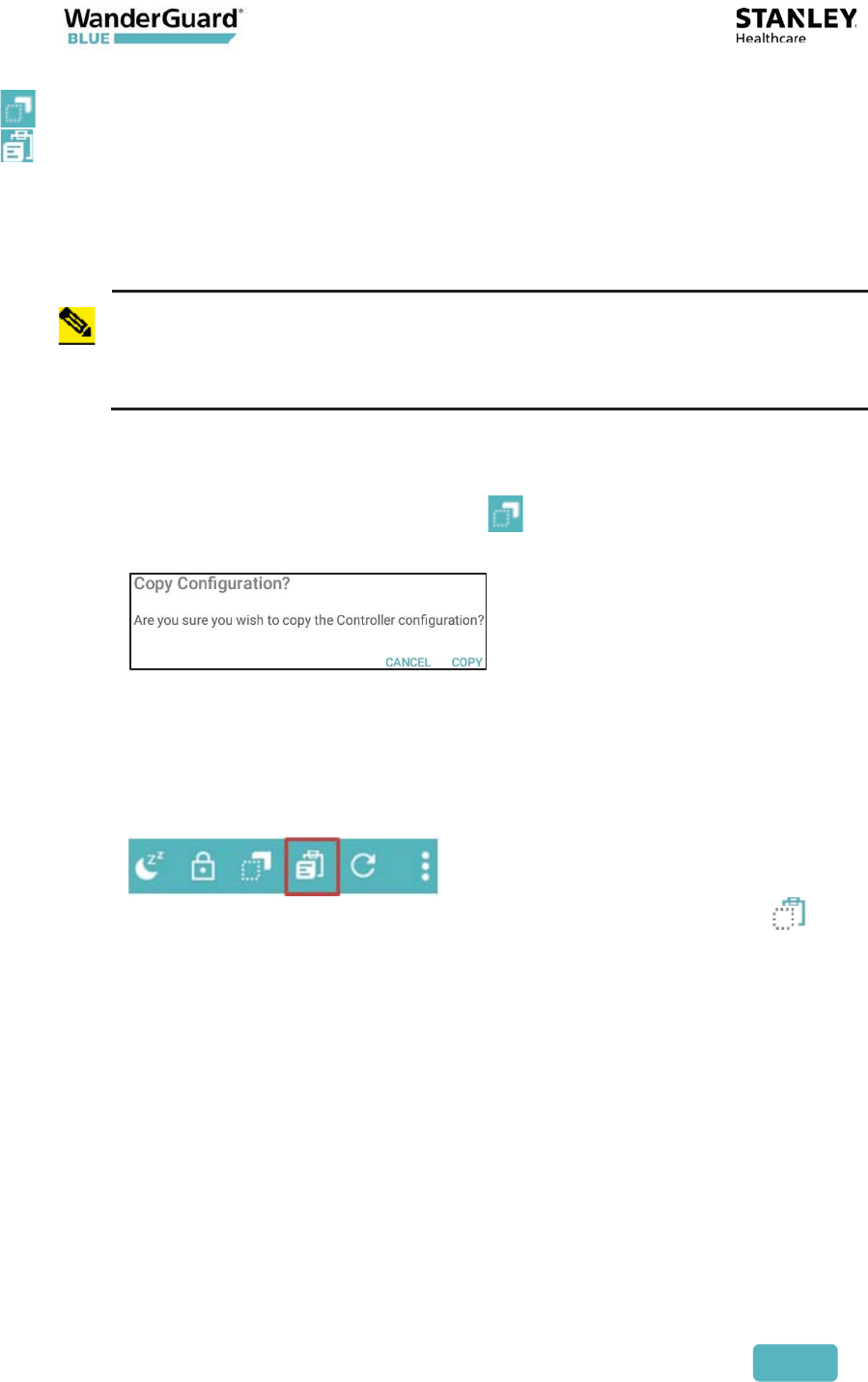
Copy / Paste Configuration
The Copy Paste function on the Toolbar is used to copy the Controller
configuration from one Controller to another. For example, if there are 45 users
defined in one Controller, they can be copied to other Controller(s) with the
entire Controller configuration.
Note
Only one Controller configuration can be saved at a time. The
configuration that was copied in WanderGuard BLUE Manager is
available to be pasted until another configuration is copied (over it), or
the WanderGuard BLUE Manager application is closed or logged out.
To copy a configuration from a source Controller to a target Controller:
1. Connect to the source Controller.
2. Click the Copy Configuration icon in the Navigation Bar.
3. A confirmation message appears:
4. Click Copy to continue.
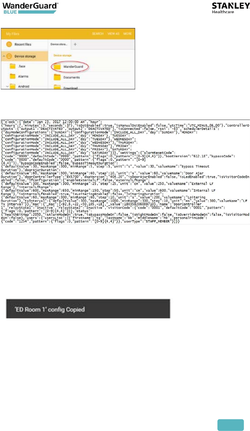
5. The configuration is copied to WanderGuard BLUE Manager. A message
momentarily appears at the bottom of the Tablet screen informing that
the configuration was copied, and a Paste icon is added to the
Navigation Bar.
In addition, a Copy icon appears in the bottom-left of the screen .
6. At this point, the configuration data is stored in the application and is
displayed on the screen in WanderGuard BLUE Manager.
The configuration remains on screen until either a new configuration is
copied or you log out of the application.
7. Disconnect from the source Controller.
User and Deployment Guide
110
Best Practice: Typically, a disconnect occurs when physically moving to
the next Controller and moving out of the BLE coverage of the
Controller. The Paste icon, however, still remains in the Navigation Panel
ready to paste into another Controller.
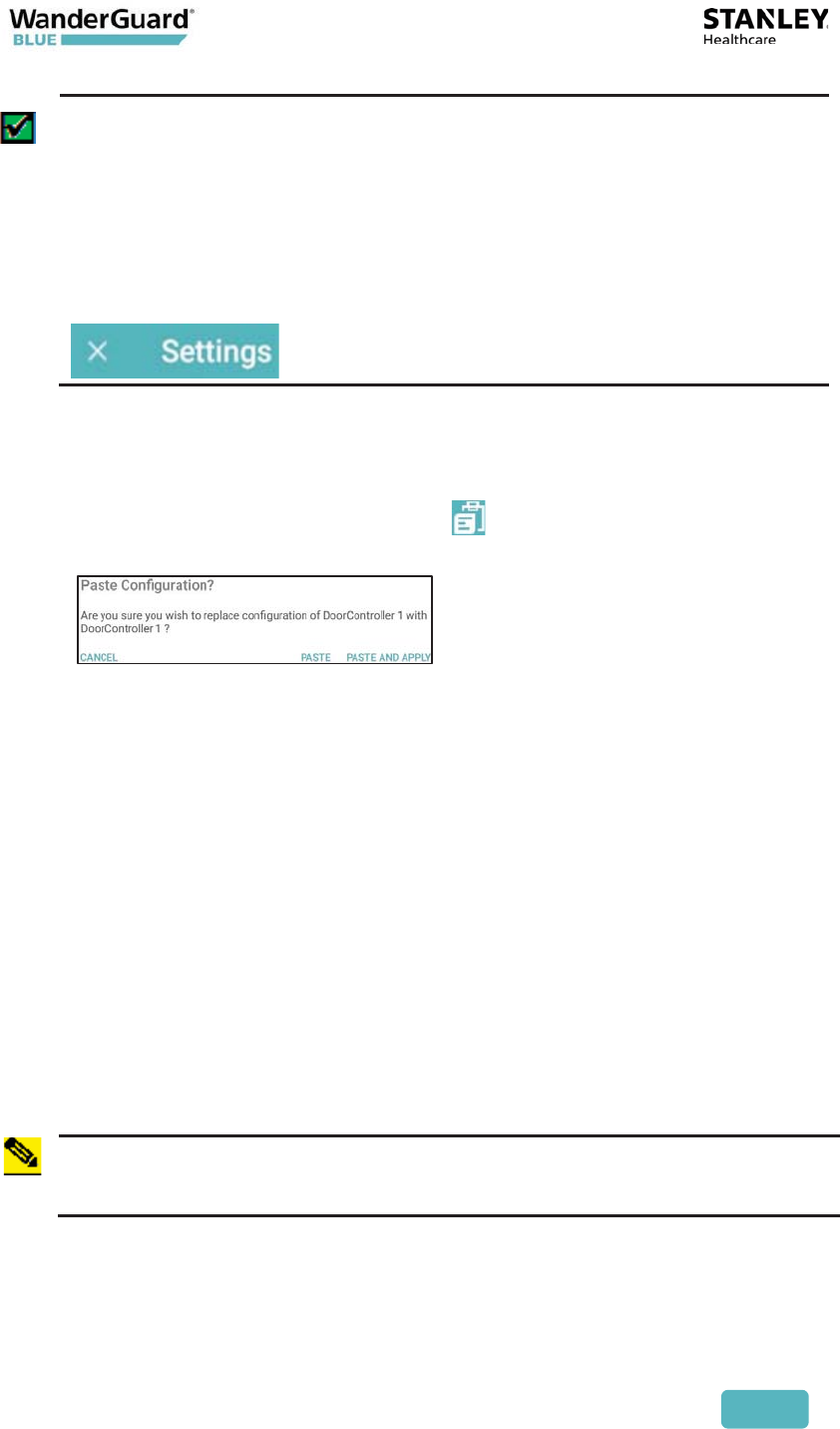
If the application is within the BLE range of a Controller, disconnecting
from the Controller can be done by leaving the configuration pages:
click "X" next to Settings at the top of your WanderGuard BLUE
Manager screen.
To paste a configuration from the source Controller to the target
Controller:
1. Connect to the target Controller.
2. Click the Paste Configuration icon in the Navigation Bar.
3. A confirmation message appears:
4. There are two options:
x Click Paste. The copied source configuration is now pasted into the
active Configuration pages. The Configuration is not applied to the
Controller.
x Click Paste and Apply. The configuration is pasted into the
WanderGuard BLUE Manager and all copied configuration pages are
applied to the target Controller.
5. The Paste option allows you to review the configuration and make
changes, if necessary, before applying it to the Controller.
x There is an option to copy specific pages to the target Controller by
navigating to those pages (for example, the Clock Settings page or
the Users page) and then clicking Apply.
x There is an option to copy the whole configuration (all the pages) to
the target Controller by clicking More and then Apply All.
Note
A copied configuration that was pasted and applied does not include the
Controller Name, Time, Date and time Zone.
User and Deployment Guide
111
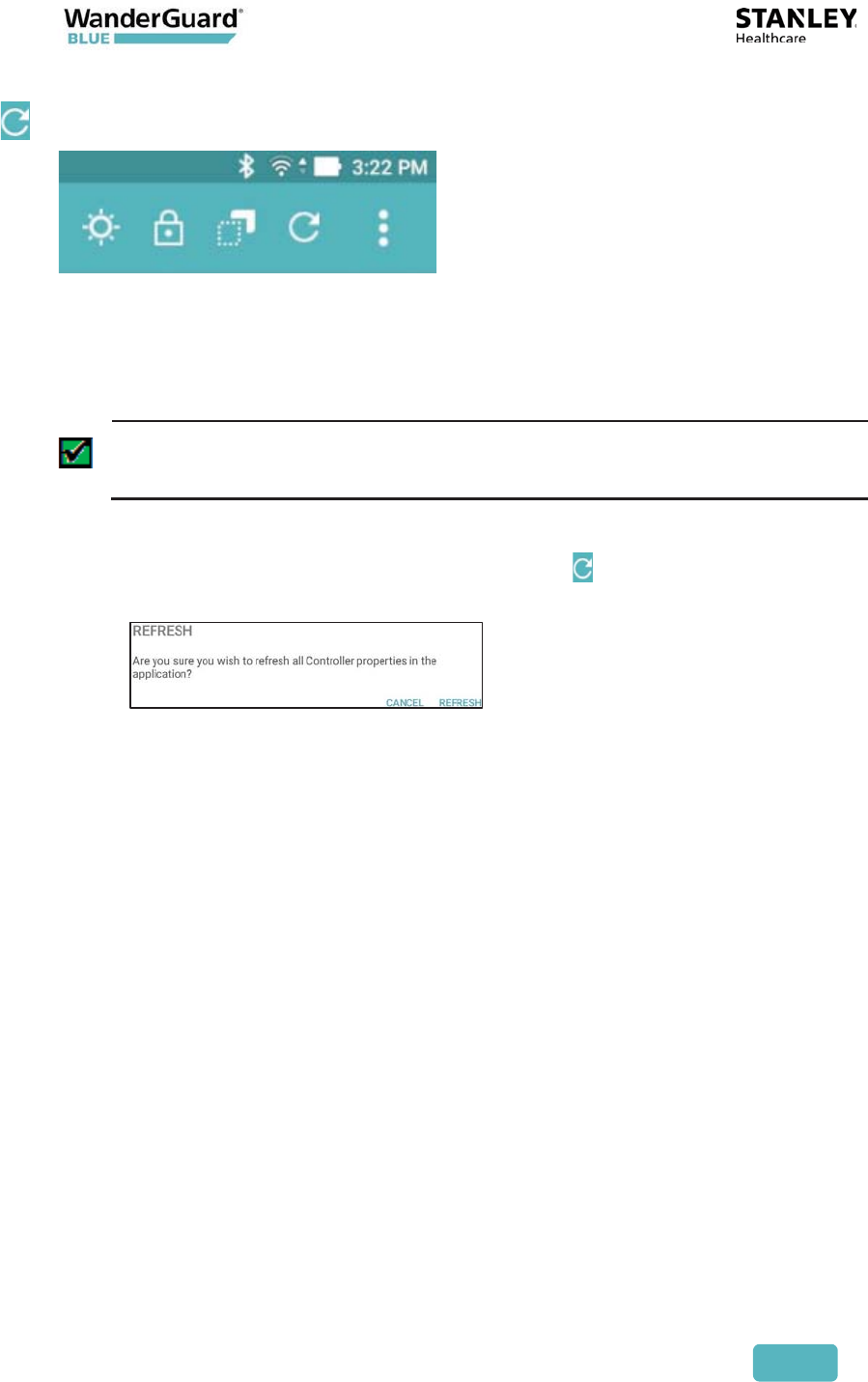
Refresh Configuration
Refresh updates the WanderGuard BLUE Manager configuration pages
(Settings, Clock, Outputs and Schedule) with the Controller configuration.
All changes that were made in the WanderGuard BLUE Manager and not
applied are refreshed.
Best Practice: Refresh is a quick way to verify configuration changes that
you made in WanderGuard BLUE Manager and applied to the Controller.
To refresh a configuration in WanderGuard BLUE Manager:
1. Click the Refresh icon in the Navigation bar .
2. A confirmation message appears:
3. Click Refresh to continue.
4. A "completed successfully" message appears at the bottom of the
WanderGuard BLUE Manager screen, and the pages are refreshed with
current data from the Controller.
User and Deployment Guide
112
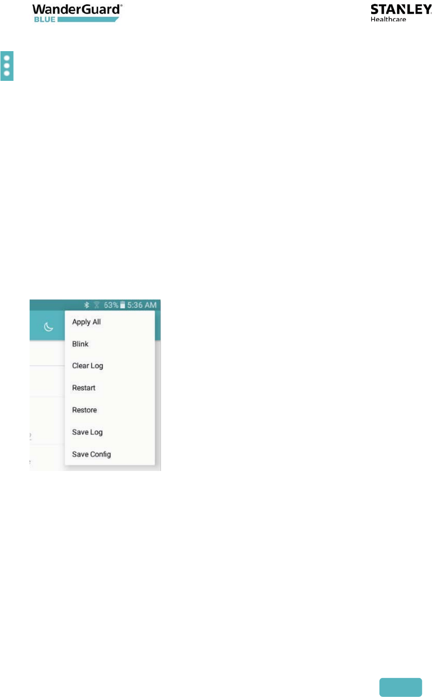
More
The More button contains other useful options for working efficiently with
WanderGuard BLUE Manager.
These include:
x Apply All – applies all configuration parameters to the Controller
x Blink – Makes the Controller "blink"
x Clear Log – Clears the Controller's Log
x Restart – Restarts the Controller
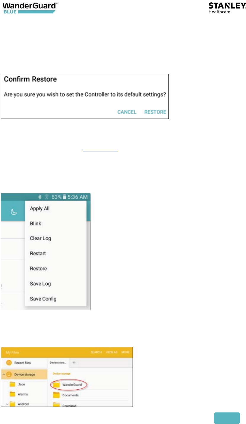
x Restore – Restores the Controller configuration to the default
configuration
x Save Log – Saves the Controller Log to a file
x Save Config – Saves the Controller Configuration to a file
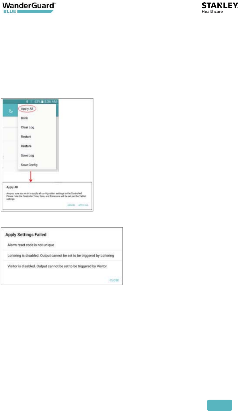
Click More to open a selection window:
User and Deployment Guide
113
Apply All
This option does the following:
x Applies the entire configuration from the WanderGuard BLUE Manager to
the Controller
x Validates the entire configuration prior to applying the configuration
x Controller’s Time (time/date/world Time Zone) is updated with the Tablet’s
time
If a validation error is found, the following error message appears:
User and Deployment Guide
114
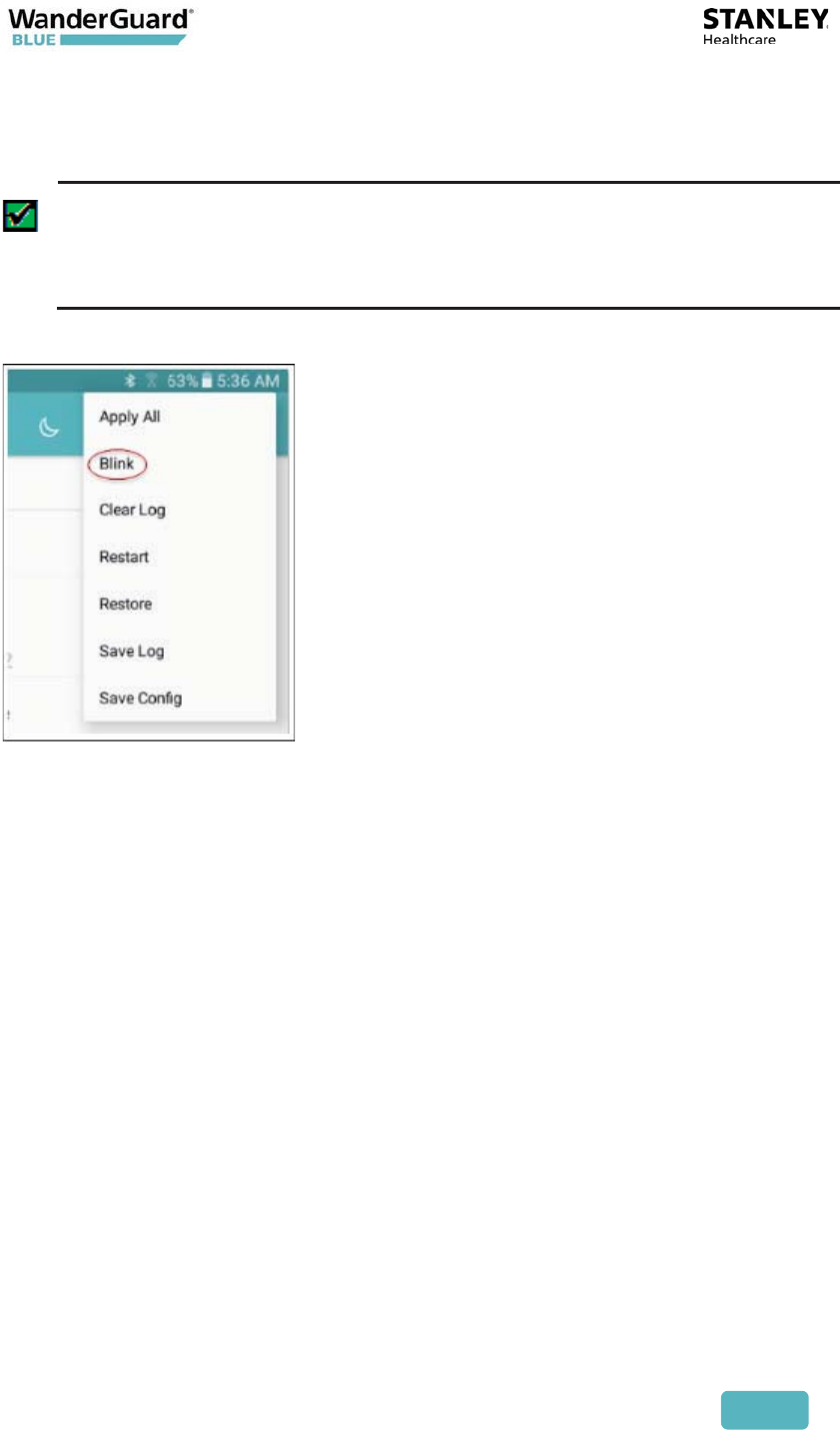
Blink
Sends a command to the Controller to flash for 5 seconds.
Best Practice: This option is useful if you are working with more than
one Controller in a specific area.
For example, if you wanted to verify that you are connected to a specific
Controller you could "blink" it.
User and Deployment Guide
115
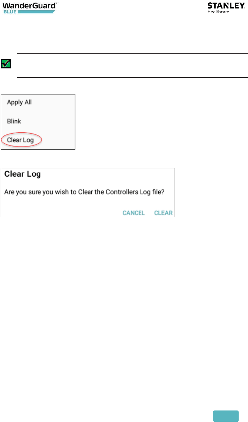
Clear Log and Save Log
Clears all log entries currently in the Controller.
Best Practice: This function is useful during maintenance to eliminate
errors and alerts that are no longer applicable.
When you click Clear Log, a confirmation message appears:
Click Clear to clear the log or Cancel to exit without clearing the log.
User and Deployment Guide
116
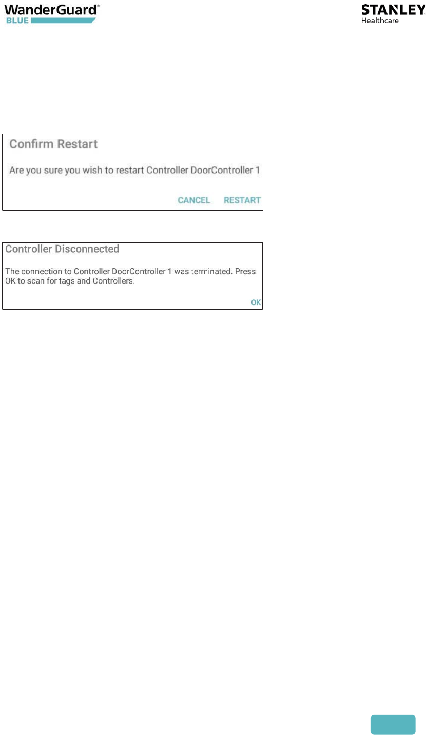
Restart
Clicking Restart power cycles the Controller. The WanderGuard BLUE Manager
application automatically jumps to the Scan page and starts the scan process.
When you select Restart, a confirmation message appears.
Click Restart. The following message appears:
Click OK to continue.
User and Deployment Guide
117
Restore
Restore returns the Controller to its default factory configuration. The default
configuration is permanently stored on the Controller.
Clicking Restore opens a confirmation message.
Click Restore to continue. When the command is successfully received at the
Controller, the Controller is returned to its default settings.
See the Default settings in Appendix C.
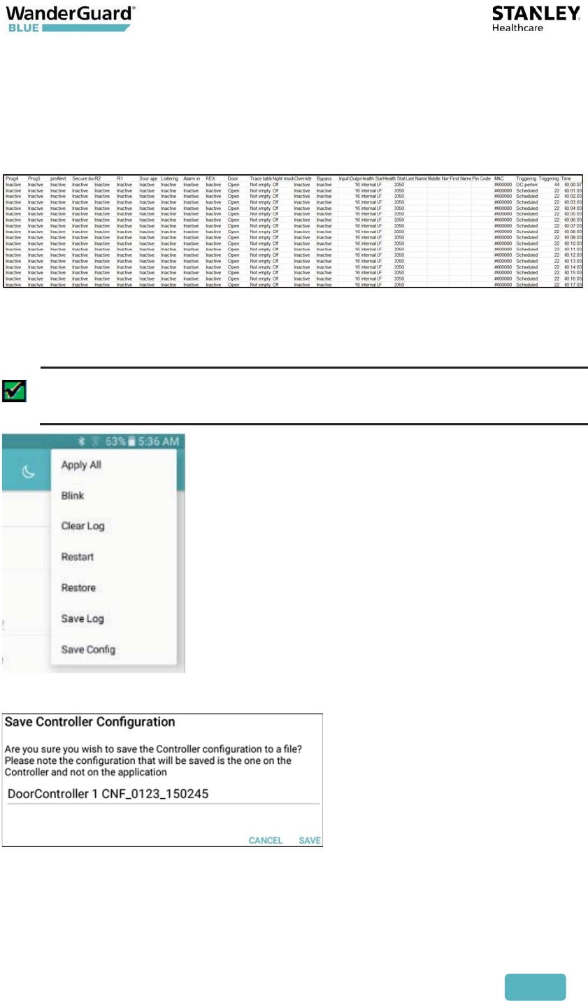
Save Log
Saves the Controller log to a CSV file. The file itself is saved to the Tablet. The
Controller log is limited to 1000 entries.
The saved log file can be viewed in Google Sheets, which is installed on the
Tablet. The file location is:
x My Files\Device storage\WanderGuard
User and Deployment Guide
118
The file name can be changed. The following are the criteria for a valid log file
name:
x 1-32 chars: a-z, A-Z, 0-9, ‘ ‘, ‘-’, ‘.’, ‘(‘, ‘)’.
The following is a typical Door Controller log file:
Save Configuration
Saves the entire Controller configuration to a text file.
Best Practice: This function is useful to STANLEY Healthcare's support
team for offline troubleshooting.
Click Save Config to open a confirmation message:
Click Save to save the configuration. The file is saved in the following location:
x My Files\Device storage\WanderGuard
User and Deployment Guide
119
Criteria for a valid file name: 1-32 chars: a-z, A-Z, 0-9, ‘ ‘, ‘-’, ‘.’, ‘(‘, ‘)’.
A typical configuration file looks like this:
Snack Bar
The Snack Bar is located at the bottom of the WanderGuard BLUE Manager
page, and a Snack bar message appears for less than three seconds. It provides
immediate feedback regarding whether the action taken by the user (Apply,
Start/End, Restore, Save, etc.) was completed successfully.
The following indications appear in the Snack Bar:
x Successful operation
x Timeout
x Failure in sending the command
User and Deployment Guide
120
Troubleshooting the Tablet Installation
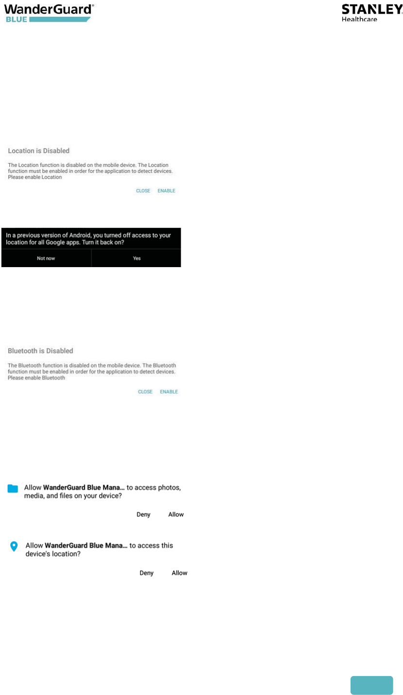
Location services
Click Enable when you receive the following message, or if Location is disabled,
enable it:
Bluetooth®
Click Enable when you receive the following message, or if Bluetooth is
disabled, enable it:
WanderGuard BLUE Manager Access
If you receive requests to allow WanderGuard BLUE Manager to access a device,
allow it.
TeamViewer
The TeamViewer application is installed on the Tablet to enable remote access
by STANLEY Healthcare service personnel.
User and Deployment Guide
121
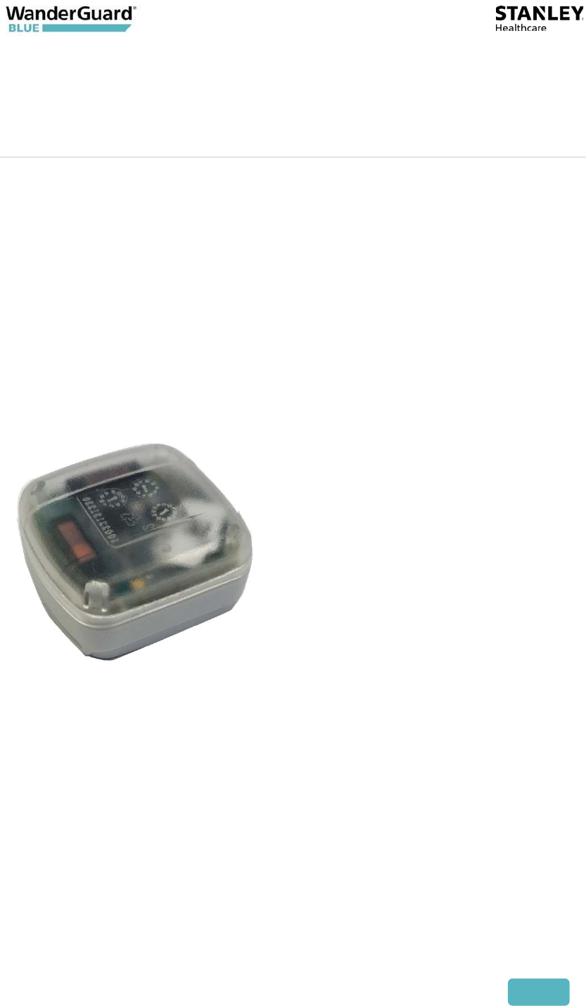
9
Detector Tag
The WanderGuard BLUE Detector Tag is intended to be used by STANLEY
Healthcare professional services personnel only. The Tag is used in order to
detect and determine the range of LF coverage near a door where a Controller
is installed. The Tag is usually used during system installation. The Detector Tag
indicates Good and Bad LF transmitted from a WanderGuard BLUE Controller,
external Antenna and slave Exciter.
User and Deployment Guide
122
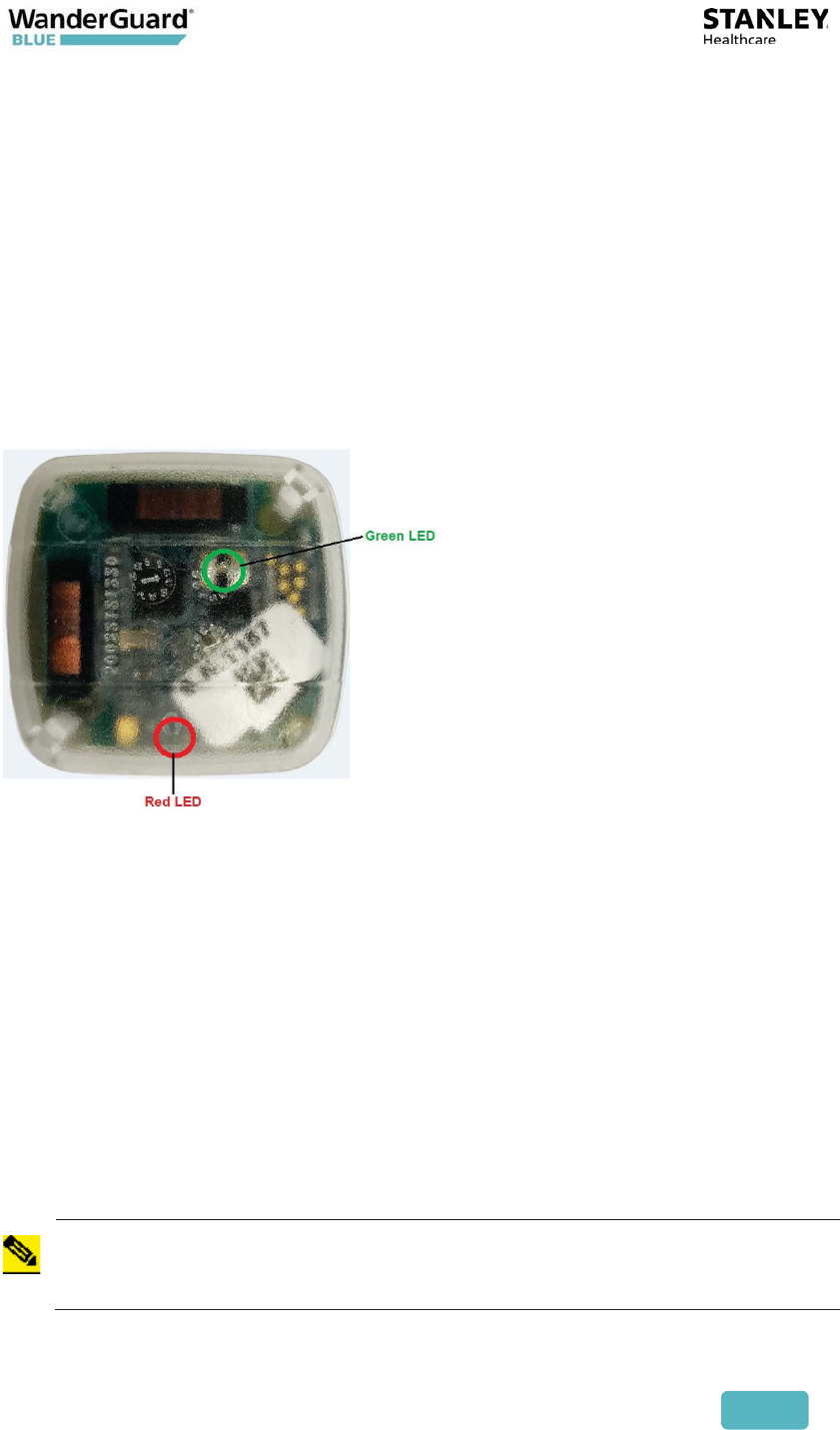
LED Indicators
The Detector Tag LED blinks when it receives LF messages from the Controller
(or Exciters) OR the WanderGuard BLUE Detector. When WanderGuard BLUE
Tags are in the Controller's range, the Detector Tag's LED blinks at the same
interval as the Controller transmission (set to 300 msec by default).
The Detector Tag has two LEDs that provide indications of LF (see table below):
x Green LED for Good LF
x Red LED for Bad LF
Activating the Detector Tag and Dormant Mode
The Detector Tag is in dormant mode by default. Activating the Detector Tag
can be done by pressing the WanderGuard BLUE Detector button on the side of
the WanderGuard BLUE Detector.
After being pressed for 1.5 seconds, a sound indication is emitted (similar to
standard Tag activation).
The Detector Tag automatically goes into Dormant Mode after five minutes if
no Controller LF signal is received, and the LEDs turn off.
If the Detector Tag enters Controller or Detector LF range, it "wakes up," and its
LEDs indicate the quality of the LF signals.
Note
The WanderGuard BLUE Detector also checks the battery status of the
Detector Tag.

User and Deployment Guide
123
Using the Detector Tag to Measure Controller
Coverage
To check LF:
1. Hold the Detector Tag.
2. Move in and out of the Controller LF coverage area, and see that the
Detector Tag(s) LED(s) blink per the LF messages that it receives.
LF Signal Red LED Green LED Comment
Good LF signal from
Controller/External
antenna/Slave Exciter
- Blinks Green
Detector Tag does not
send BLE message upon
receiving the LF messages
Bad LF signal from
Controller/External
antenna/Slave Exciter
Blinks Red - Received LF message with
CRC that is not correct
Good LF from
WanderGuard BLUE
Detector
No indication on LEDs Detector Tag transmits
BLE
LF received NOT coming
from WanderGuard
BLUE Controller or Tags
No indication on LEDs (no
good or bad LF indicated)
Does not transmit BLE

User and Deployment Guide
124
Detector Tag Specifications
Specifications
Part Number SKU: WGB-DETAG-1000
MAC address 3 LSB printed on its side similar to WanderGuard
BLUE Tags
LF Frequency 125 kHz
BLE Frequency 2400-2483.5 MHz
Battery Life Three years

User and Deployment Guide
125
10
Appendix A: Mounting the EX5700
Controller – Ceiling Mounting
Position and mount each EX5700 Controller in the site according to the site
survey recommendations.
Mounting Limitations
In a secured door deployment involving electrical devices transmitting signals at
125 kHz (such as card readers or time stamp clocks), LF interference can exist in
the Controller’s LF field. The LF interference causes Tags to lose the Controller’s
LF signal making the Tag location appear outside of the Controller’s LF field.
This may result in a door releasing when a Tag is in range of the Controller’s LF
field.
To resolve this issue:
x Make sure the Controller is mounted vertically in order to increase the LF
propagation
x Increase the LF range of the Controller
x If possible, place the interfering device (such as the card reader) outside
of the Controller’s LF field.
x If needed, connect LF External Antenna, and place it above the
interfering device
User and Deployment Guide
126
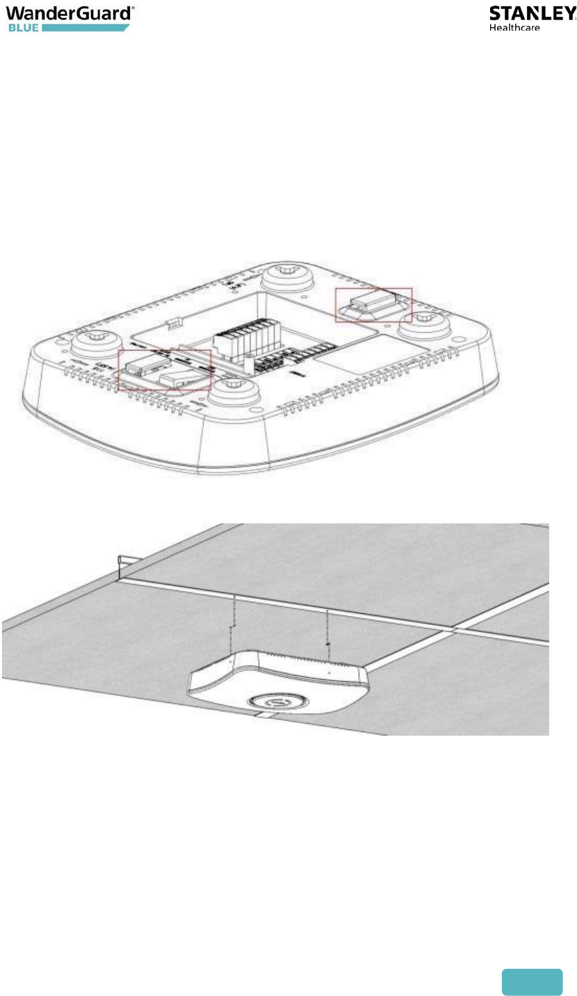
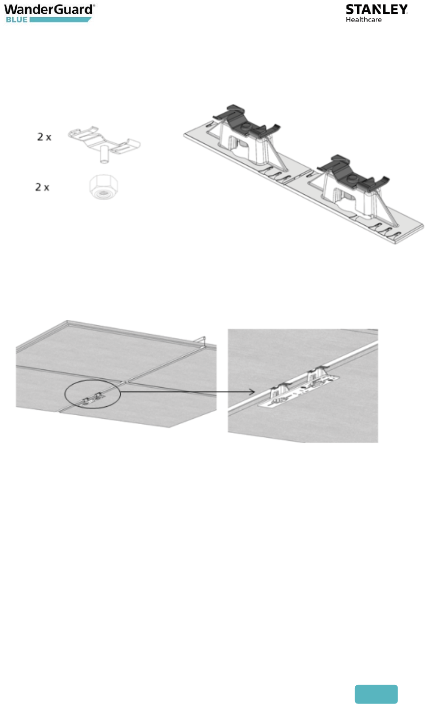
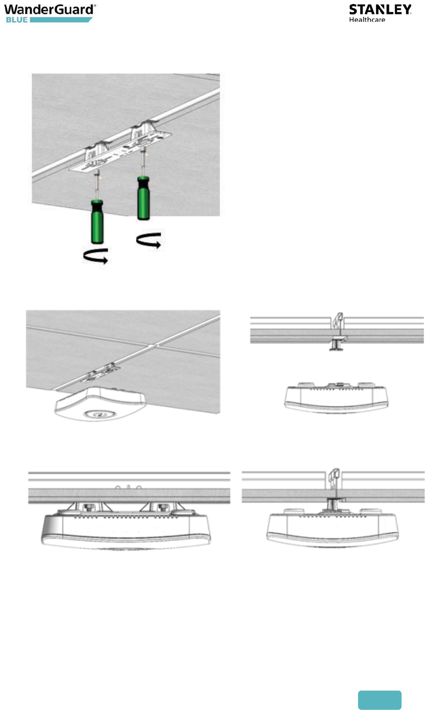
Fixing the Controller to a Floating Ceiling:
Mounting on a Wide Grid with Flush Tiles
For this mounting option no mounting kit is required. Attach the device to the
false ceiling using the ceiling mounts located on the bottom casing of the
device.
1. Align the Mounting clips with the wide grid.
User and Deployment Guide
127
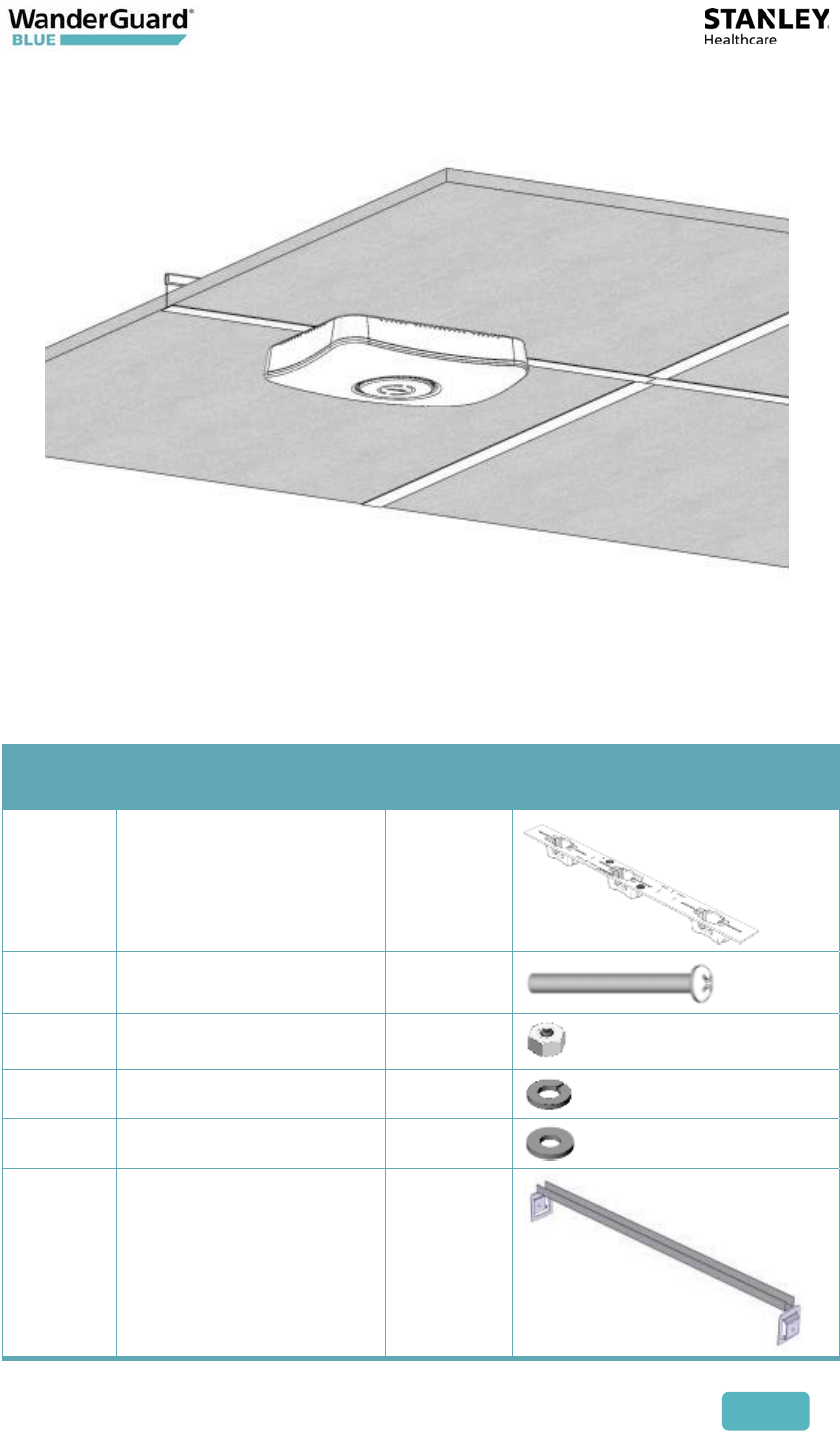
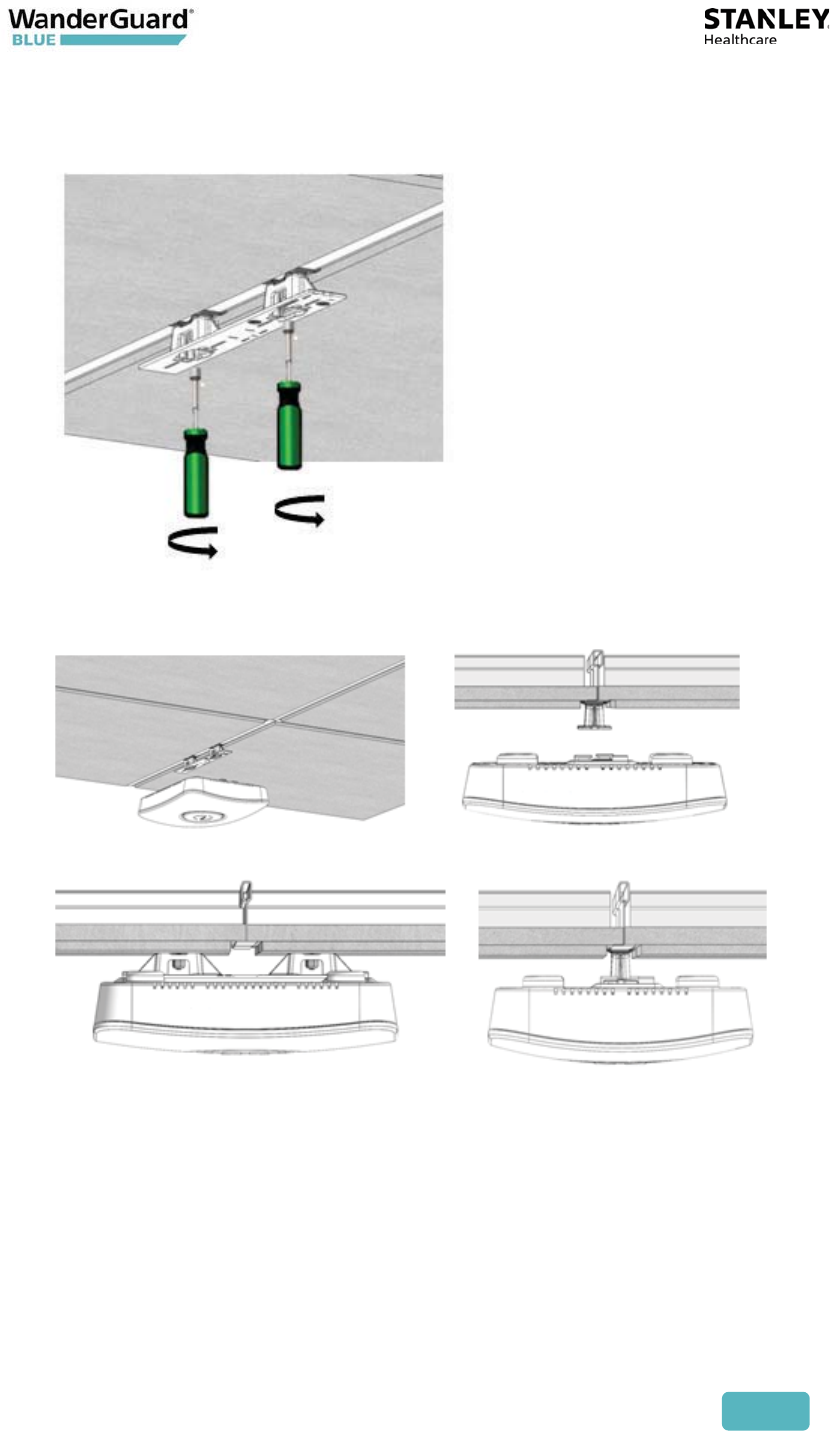
2. Twist and click the Exciter into place.
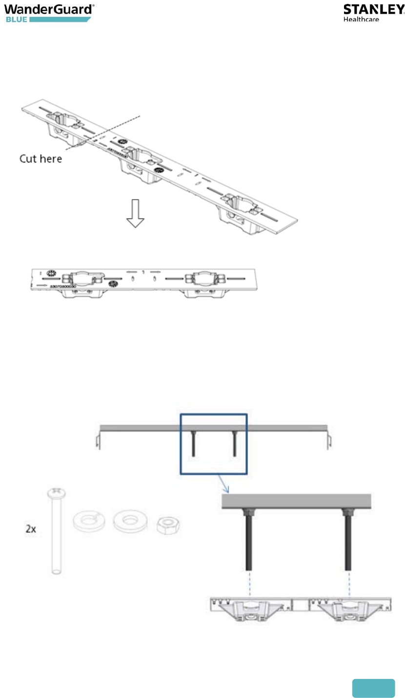
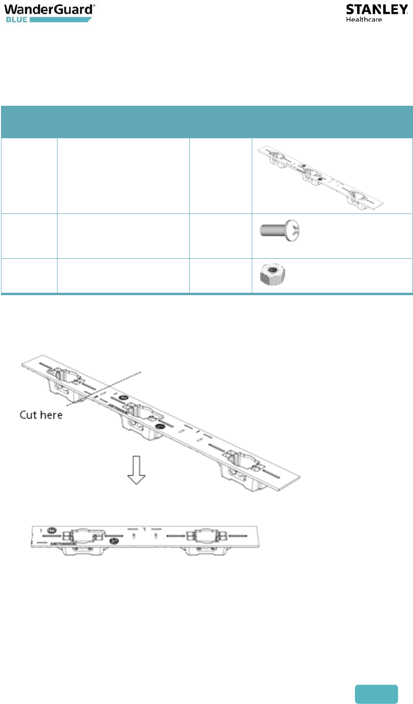
Mounting Off-Grid
For this mounting option the following parts from the Heavy Duty Kit (WGB-
EXAC-HDUTY-1000) are required:
Part
Letter Part Name Quantity Images
A Mounting Adaptor 1
E ¼” x 3” Phillips Screw 2
G ¼” Hex Nut 6
I ¼” Spring washer 2
H ¼” Flat washer 2
D Bracket 512HD 1
User and Deployment Guide
128
1. Cut the Mounting Adaptor (A) so that only Section # 1 remains.
Use Mount Adaptor part marked with “<= 1 =>”
2. Step 2 – Fasten 2 Screws (E) on the 512HD Bracket (D) with 1 Flat Washer (H)
and 1 Spring Washer (I). Set the distance between the Screws using the
Adaptor (A).
User and Deployment Guide
129
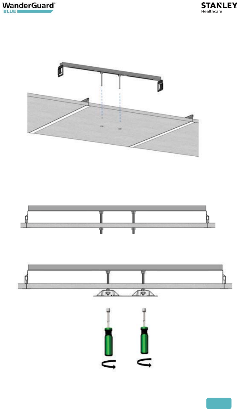
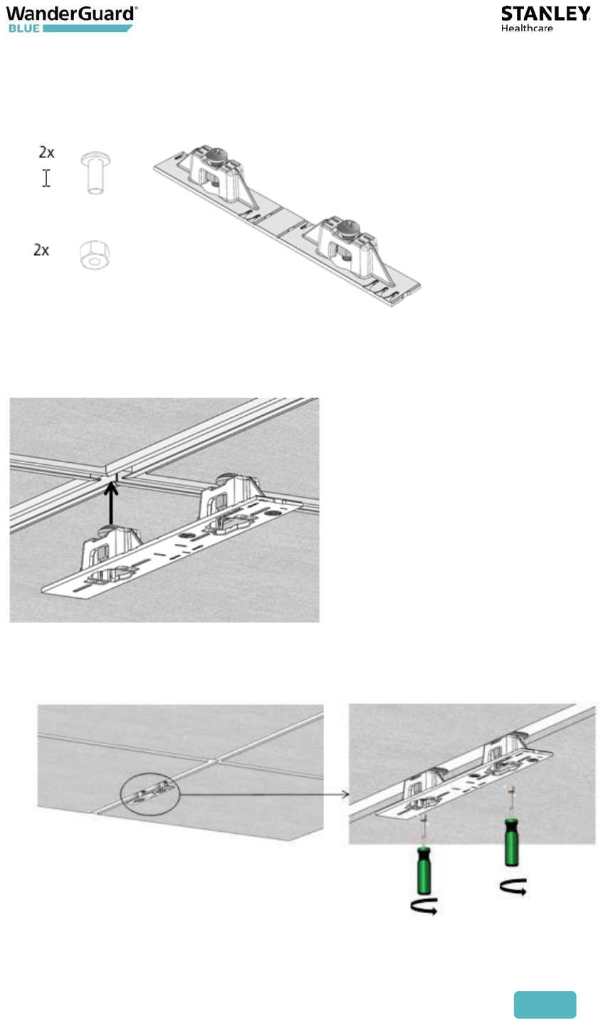
3. Drill 2 holes* in the designated for installation ceiling tile for the Screws (E).
Use the assembled 512HD Bracket (D) to mark the location of the holes.
* Holes should be 5/16” or 8 mm in diameter
4. Mount the Assembled 512HD Bracket (D) on the tile. Fix in place 2 Nuts (G)
on each of the Screws (E) leaving enough screw length (2/5” or 10 mm) to
mount the Adaptor.
5. Mount the Adaptor using 2 Nuts (G) using a 7/16” nut driver.
User and Deployment Guide
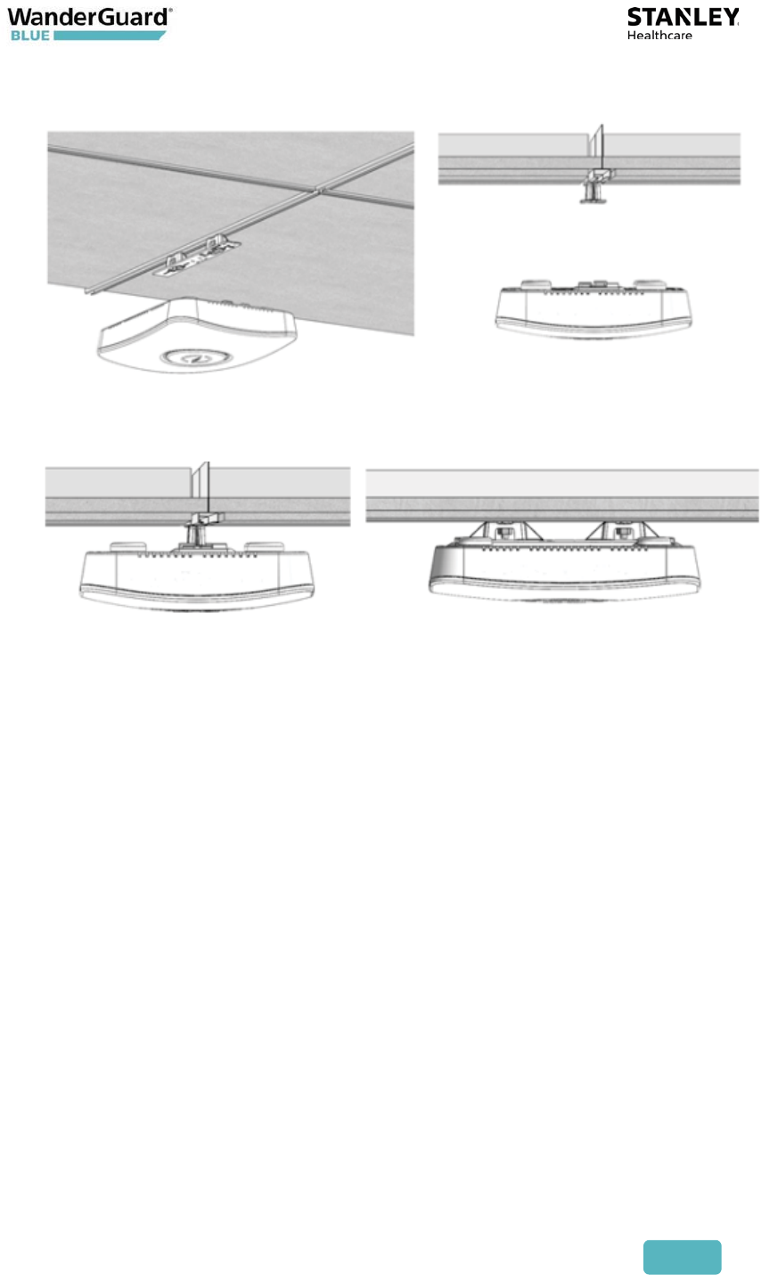
130
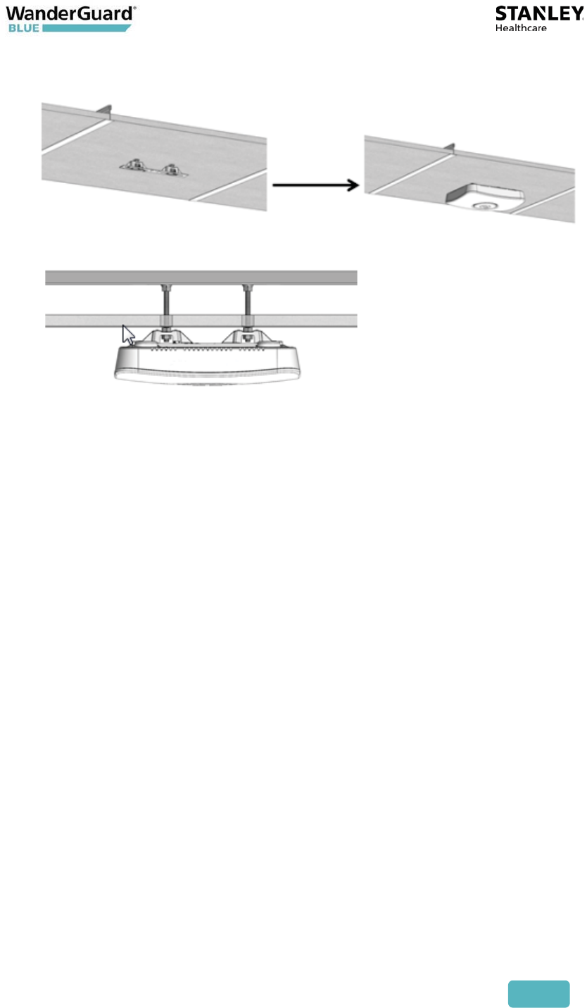
6. Mount the Exciter onto the Adaptor (A) on the ceiling tile.
User and Deployment Guide
131
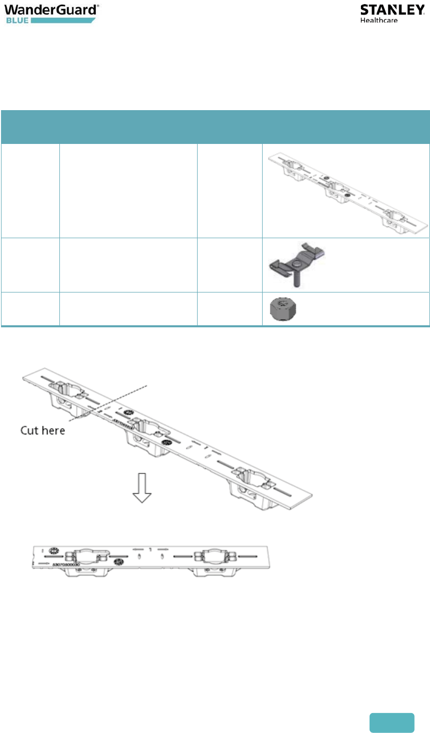
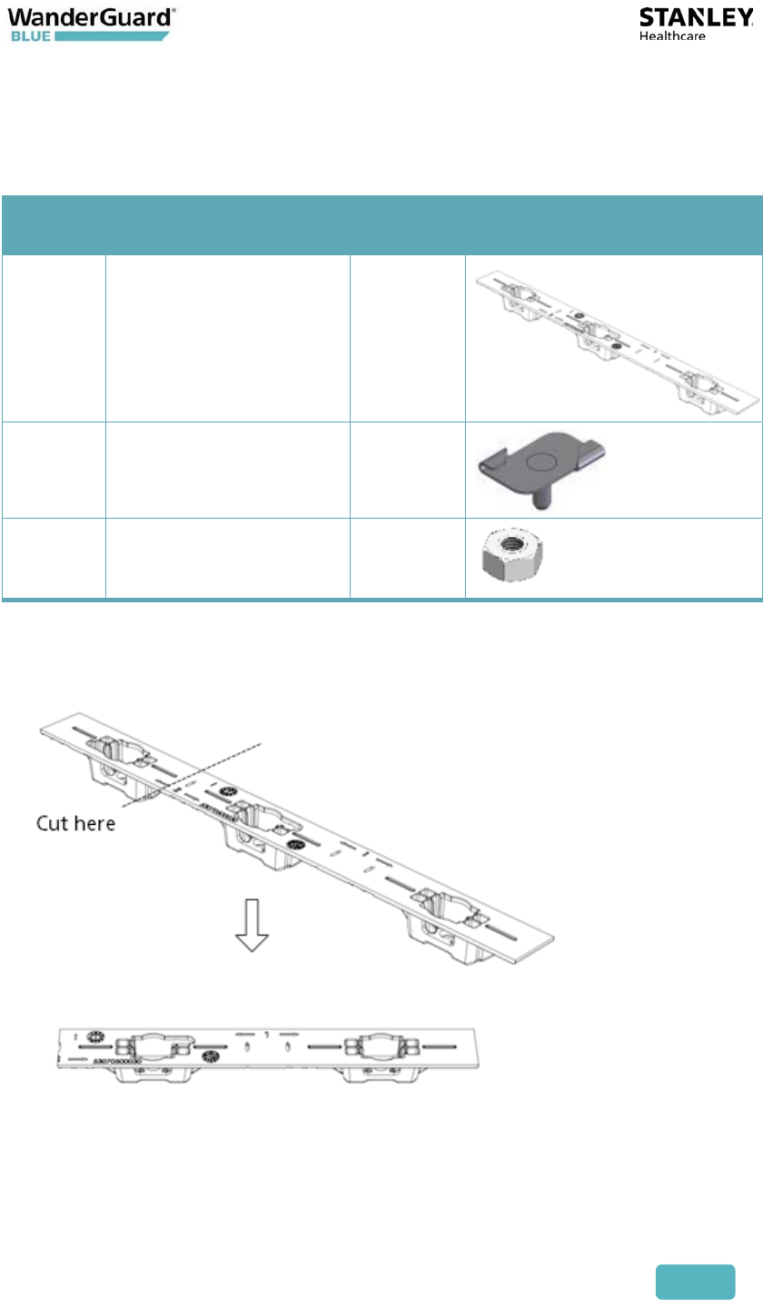
Mounting on a Narrow-Grid T-Bar
For this mounting option the following parts from the Standard Kit
(WGB-EXAC-STD-1000) are required:
Part
Letter Part Name Quantity Images
A Mounting Adaptor 1
C Narrow Grid Clip- 9/16”
Clip with #8 Stud
2
J #8-32 Hex Nyloc Nut 2
1. Cut the Mounting Adaptor (A) so that only Section # 1 remains.
Use Mount Adaptor part marked with “<= 1 =>”
User and Deployment Guide
132
2. Assemble the Grid Clips (C) on the Adaptor (A). Lock each Clip (C) with Hex
Nut (J). The Nuts should be loose at this stage to allow easy insertion
onto the grid.
3. Attach the Grid Clips (C) with Mount Adaptor (A) onto the ceiling grid.
(Push the clips against the grid and twist them until they lock) (turn
clockwise).
User and Deployment Guide
133
4. Fasten the Adaptor (A) to the Clips (C) by tightening Nuts (J) into their final
position using a 11/32" Nut Driver.
5. Mount the Exciter onto the Mounting Adaptor (A).
User and Deployment Guide
134
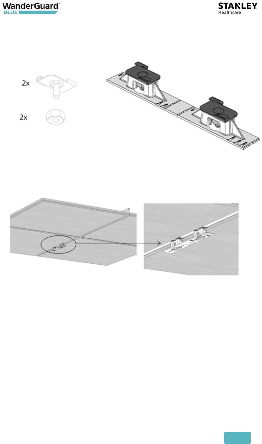
Mounting on a Wide Grid with Recessed Tiles
For this mounting option the following parts from the Standard Kit
(WGB-EXAC-STD-1000) are required:
Part
Letter Part Name Quantity Images
A Mounting Adaptor 1
B Wide Grid Clip-15/16”
Clip with 1/4" Stud
2
G 1/4" Hex Nut 2
1. Cut the Mounting Adaptor (A) so that only Section # 1 remains.
Use Mount Adaptor part marked with “<= 1 =>”
User and Deployment Guide
135
2. Assemble the Grid Clips (B) on the Adaptor (A). Lock each clip (B) with Hex
Nut (G). Nuts should be loose at this step to allow easy insertion onto the
grid.
3. Attach the Grid Clips (C) with Mount Adaptor (A) onto the ceiling grid.
(Push the clips against the grid and twist them until they lock). Fasten the
Clip’s stud (B) against the grid using a flat screwdriver (turn clockwise).
User and Deployment Guide
136
4. Tighten Nuts (G) to final position using a 7/16" Nut Driver.
5. Mount the Exciter onto the Mounting Adaptor (A).
User and Deployment Guide
137
Mounting on a Slotted Grid
For this mounting option the following parts from the Standard Kit
(WGB-EXAC-STD-1000) are required:
Part
Letter Part Name Quantity Images
A Mounting Adaptor 1
F For Slotted Grid-
1/4"x0.625" Phillips
screw
2
G 1/4" Hex Nut 2
1. Cut the Mounting Adaptor (A) so that only Section # 1 remains.
Use Mount Adaptor part marked with “<= 1 =>”
User and Deployment Guide
138
2. Assemble the Screws (F) on the Adaptor. Lock each Screw (F) with Hex Nut
(G) *Nuts should be loose at this step to allow easy insertion into the slotted
grid.
3. Mount the Adaptor (A) onto the Slotted-Grid by sliding the screw heads,
Screw (F), through the slots.
4. Fasten the Adaptor to the Screws (F) by tightening Nuts (G) to their final
position using a 7/16" Nut Driver.
User and Deployment Guide
139
5. Mount the Exciter onto the Mounting Adaptor (A).
User and Deployment Guide
140
11
Appendix B: Mounting the EX5700
Controller – Wall Mounting
This appendix contains wall mounting instructions and options for the EX5700
Controller.
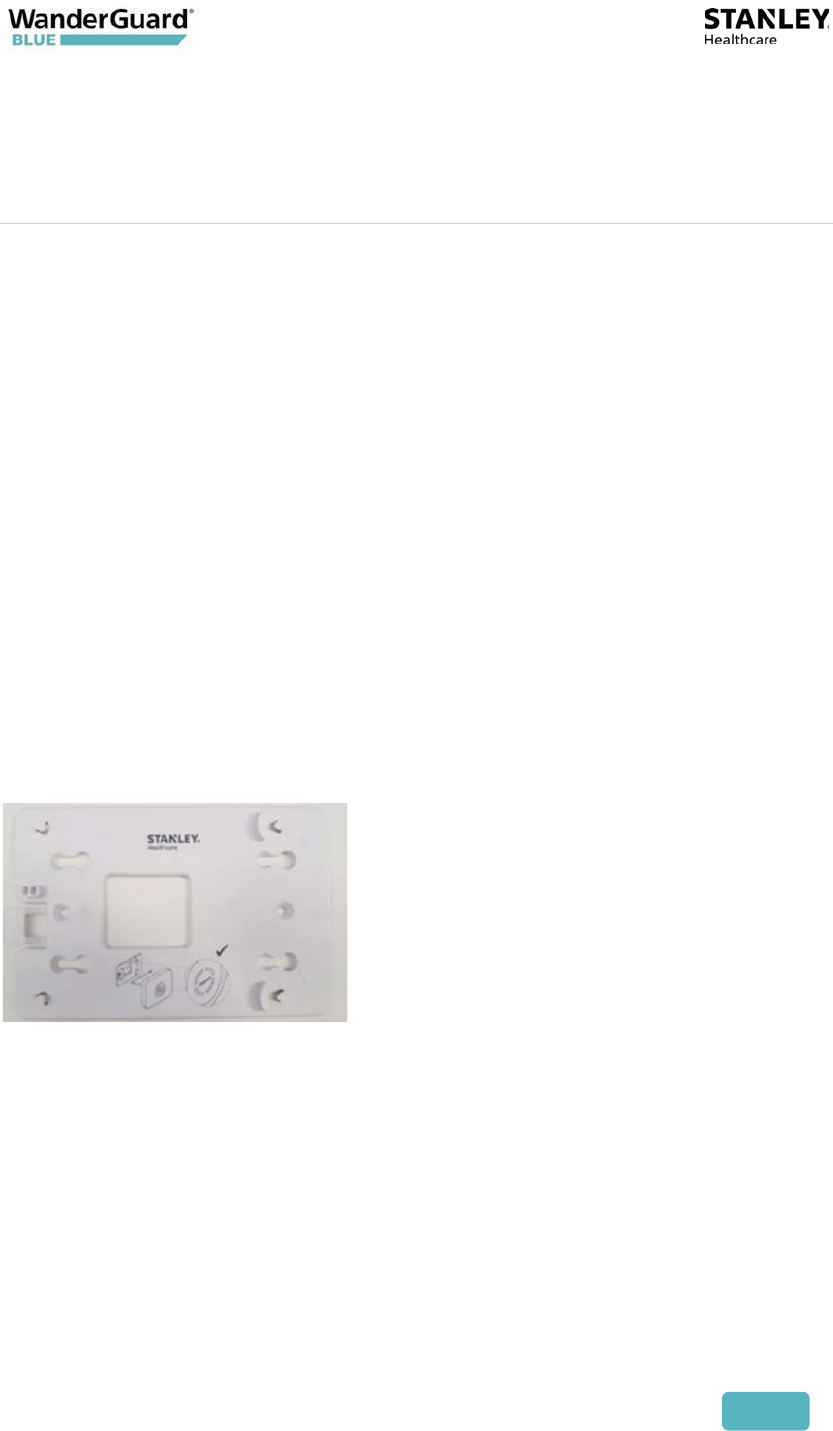
Wall (and Ceiling) Mounting Using the Plastic
Adapter
The EX5700 Controller is shipped with a mounting plate (plastic adapter). The
adapter can be used for Wall Mounting. It can also be used for Ceiling
Mounting when there are hard ceilings at the facility.
1. Hold the adapter on the wall/ceiling in the location you wish to mount
the Controller. Make sure the adapter is level.
2. Mark the four holes for the screws through the template.
3. Remove the adapter.
4. Drill the holes for the screws.
5. Anchor the screws into the wall, leaving 10 mm of each of the screws
exposed. Use appropriate screws and or anchoring plugs.
6. Mount the plastic adapter to the wall.
7. Attach the Controller to the Adapter.
User and Deployment Guide
141
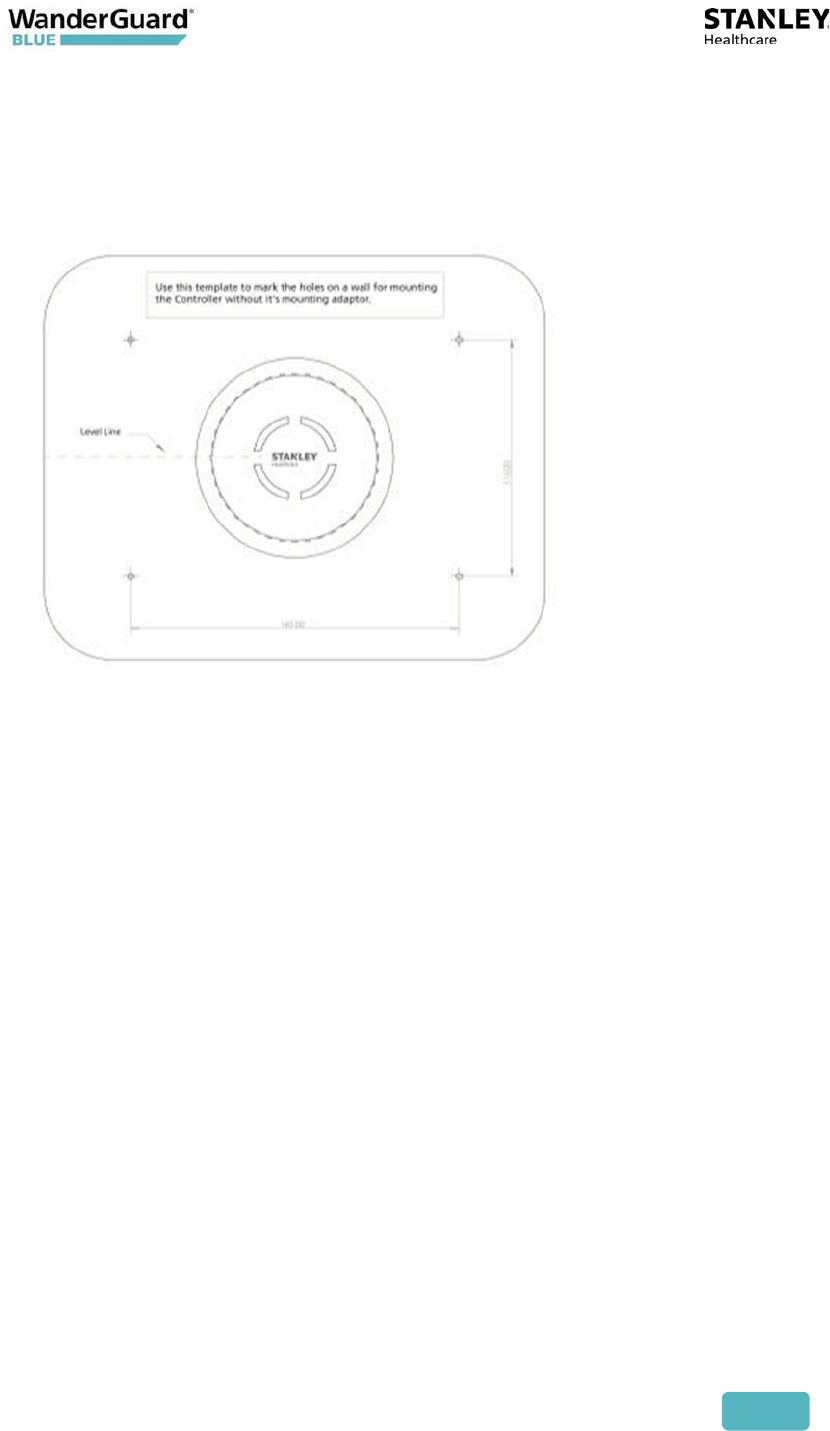
Wall Mounting Using a Template
The EX5700 Controller is shipped with a mounting template that can be used to
measure the holes for mounting the Controller on a wall. The mounting adapter
supplied with the Controller is not required in this option.
1. Hold the template on the wall in the location you wish to mount the
Controller. Make sure the template is level.
2. Mark the four holes for the screws through the template.
3. Remove the template.
4. Drill the holes for the screws.
5. Anchor the screws into the wall, leaving 10 mm of each of the screws
exposed. Use appropriate screws and or anchoring plugs.
6. Mount the Controller with the STANLEY Healthcare logo facing up, onto
the 4 screws. The Controller's back panel has 4 mounting brackets for
this purpose.
User and Deployment Guide
142
Wall Mounting Using the Wall Mount Kit
The EX5700 Controller Wall Mount Bracket (SKU EXAC-143) is used as the
mounting device when the EX5700 Controller is installed on a brick wall or dry
wall. Wall mounting is the recommended solution when ceiling mounting is not
appropriate.
Note
Wall mounting is recommended when the ceiling is too high. High-
ceiling mounting requires that the device emit increased LF power
to cover the required area. Strong LF power is not desirable
because of possible LF interference or leakage to other areas.
User and Deployment Guide
143
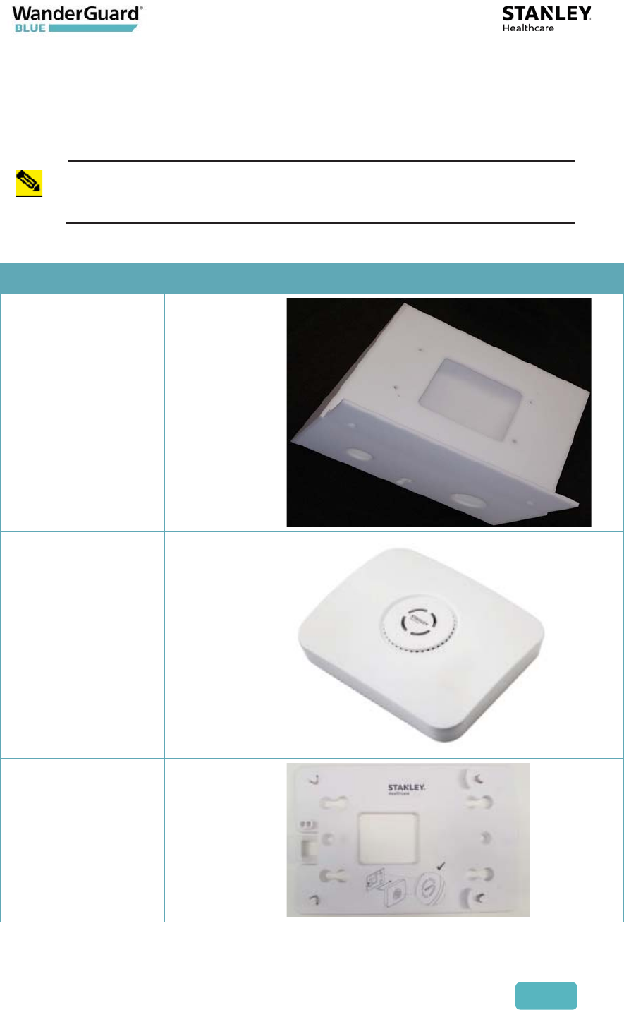
Installation Components
Before beginning, verify that you have all the items in the following table.
Note
These instructions assume that you have a standard toolkit readily
available.
Part Name Quantity Image
Wall-mount
Bracket
1
EX5700 Controller
1
Plastic Adapter
Plate
(Note on-plate
mounting
instructions)
1
User and Deployment Guide
144
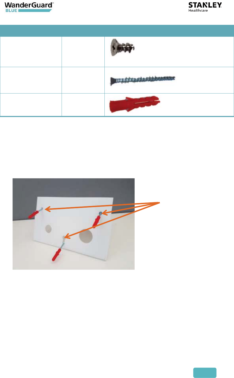
Part Name Quantity Image
PT Screw 4
Flat Head Screw 3
Plastic Anchor 3
Installation Instructions
To perform wall mounting, do the following:
1. Mark the wall, and drill holes for the plastic anchors.
1. Insert three plastic anchors into their respective holes in the wall.
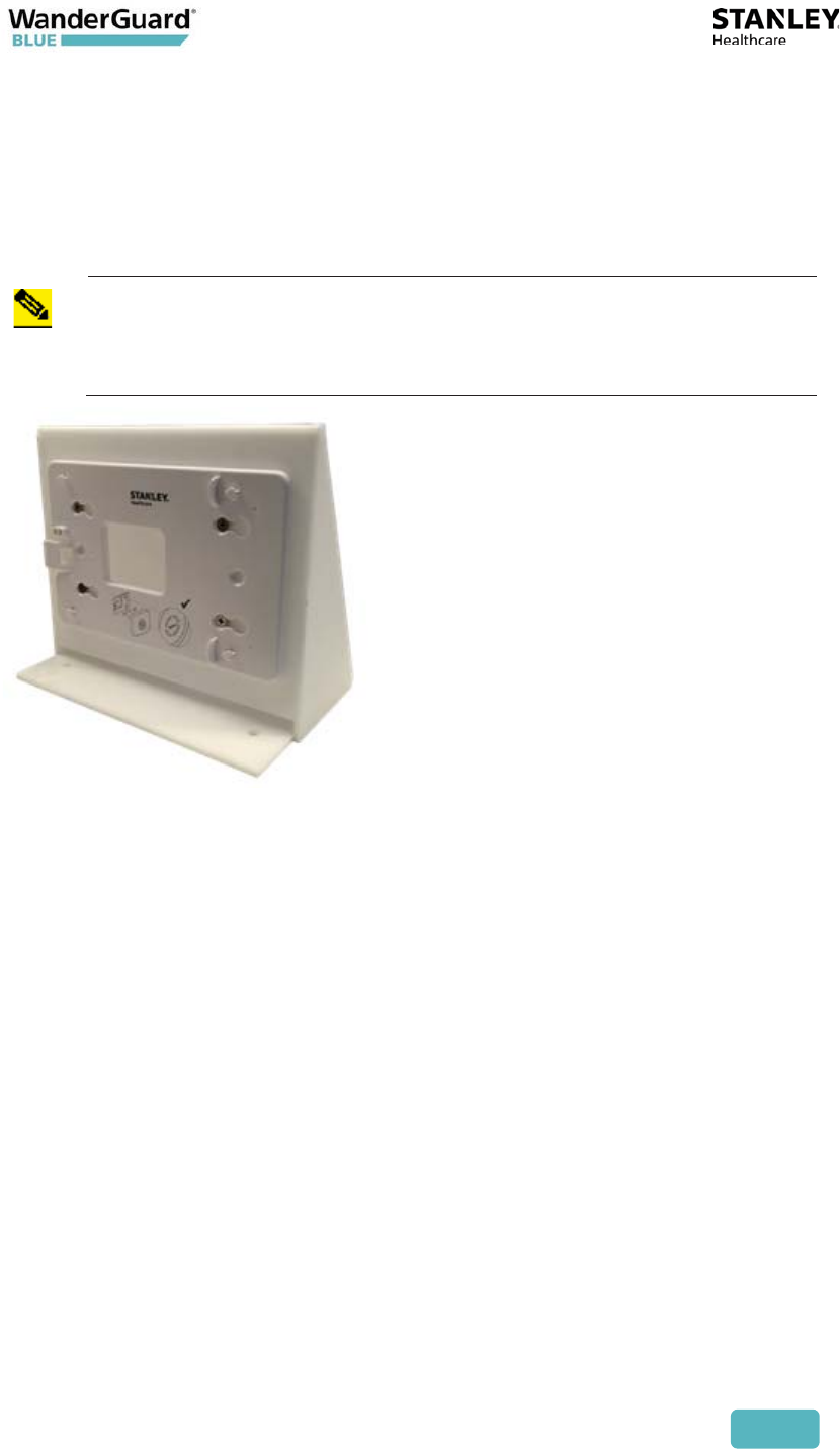
2. Attach the Plastic Adapter Plate into the Wall-mount Bracket.
To do this, align the Plastic Adapter Plate's four holes with the four
respective holes in the bracket, and assemble with the four PT screws. If
using an electric drill, use caution in order not to crack the Perspex.
When assembling, take care that the Plastic Adapter Plate's orientation is in
the upright position (see picture below).
Mounting
holes and
plastic
anchors
User and Deployment Guide
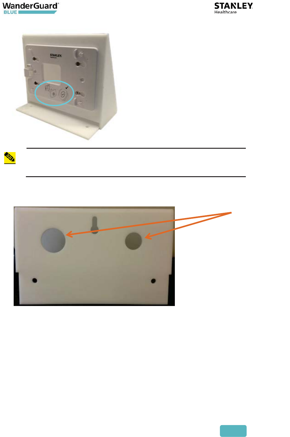
145
Note
There is a Controller attachment diagram on the Plastic Adapter
Plate. This diagram is referred to in step 7, when you attach the
Controller to the Plastic Adapter Plate.
3. Draw the cables though the Wall-mount Bracket cable holes.
Cable
holes
User and Deployment Guide
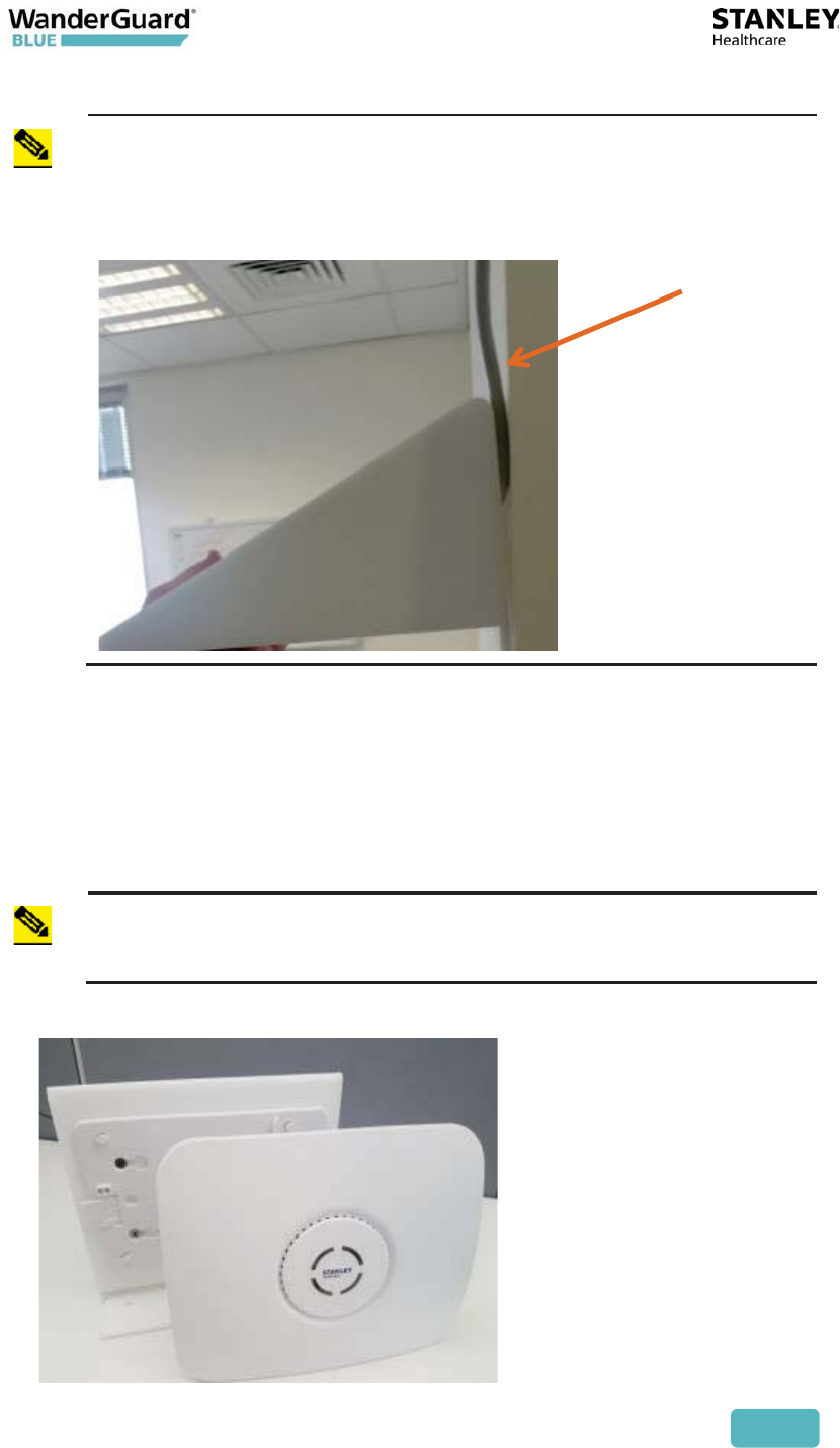
146
Note
It is recommended to run the cables through the wall. If the cable
outlet, however, is not situated near the Bracket mounting point or
it is not possible to run the cables through the wall, you can
optionally affix the cables to the wall externally and then draw
them into the Wall-mount Bracket.
4. To attach the Wall-mount Bracket on the wall (with the cables drawn
through it), assemble the 3 flat-head screws through the Wall-mount
Bracket onto the 3 plastic anchors. Tighten the flat-head screws with a
screw driver to affix the Wall-mount Bracket to the wall.
5. Connect the cables to the Controller.
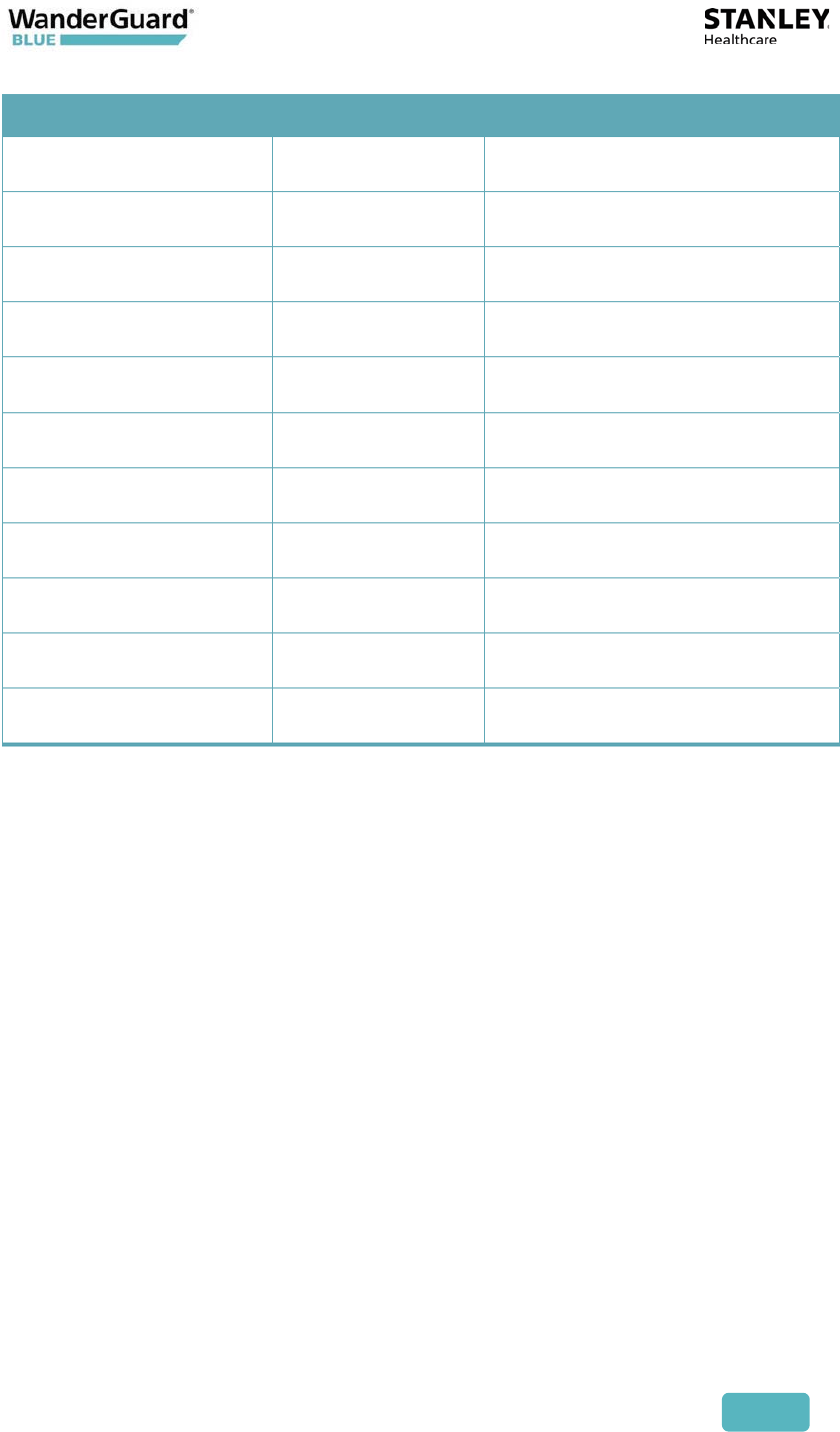
6. Attach the Controller to the Plastic Adapter Plate.
Note
The Plastic Adapter Plate has an attachment diagram printed on it
(see step 2).
External
cables
affixed to
wall

User and Deployment Guide
147
12
Appendix C: Controller Default
Configuration Settings
Parameter Setting Value
Users None
Schedule For all days – "Day Mode-
Always"
Programmable Outputs Inactive
Controller Name DoorController1
Clock
Time 12:00:00AM
Date 01/01/2017
World Time Zone UTC-5 (Eastern US and Canada)
DST Enabled
Internal LF
LF Enabled
Exciter range 600 cm
User and Deployment Guide
148
Parameter Setting Value
External LF
LF Disable
LF range Empty
Bypass timeout 30 sec
Bypass code Disable
Reset code 9999
Visitor code Disabled
Door Ajar Disabled
Loitering Disabled
Relay 1 Normally inactive
Relay 2 Normally inactive

User and Deployment Guide
149
FCC Compliance Statement
This device has been tested and found to comply with the limits for a Class B
digital device, pursuant to Part 15 of the FCC Rules. These limits are designed to
provide reasonable protection against harmful interference in residential
installations. This equipment generates uses and can radiate radio frequency
energy and, if not installed and used in accordance with the instructions, may
cause harmful interference to radio and television reception.
However, there is no guarantee that interference will not occur in a particular
installation. If this device does cause such interference, which can be verified by
turning the device off and on, the user is encouraged to eliminate the
interference by one or more of the following measures:
– Re-orient or re-locate the receiving antenna.
– Increase the distance between the device and the receiver.
– Connect the device to an outlet on a circuit different from the one that
supplies power to the receiver.
– Consult the dealer or an experienced radio/TV technician.
WARNING! Changes or modifications to this unit not expressly approved by the
party responsible for compliance could void the user’s authority to operate the
equipment.
This device complies with FCC Rules Part 15: Operation is subject to two
conditions: (1) This device may not cause harmful interference, and (2) this
device must accept any interference that may be received or that may cause
undesired operation.
This device complies with Industry Canada licence-exempt RSS standard(s).
Operation is subject to two conditions:
(1) This device may not cause harmful interference, and (2) this device must
accept any interference that may be received or that may cause undesired
operation.
Le present appareil est conforme aux CNR d'Industrie Canada applicables aux
appareils radio exempts de licence. L'exploitation est autorisee aux deux
conditions suivantes :(1) l'appareil ne doit pas produire de brouillage, et (2)
l'utilisateur de l'appareil doit accepter tout brouillage radioelectrique subi,
meme si le brouillage est susceptible d'en compromettre le fonctionnement.
A distance of at least 20 cm. between the EX5700 and all persons should be
maintained during the operation of the equipment.
Une distance d'au moins 20 cm. entre EX5700 et toutes les personnes devraient être
maintenues pendant le fonctionnement de l'équipement

User and Deployment Guide
150
About STANLEY Healthcare
STANLEY Healthcare provides over 5,000 acute care hospitals and 12,000 long-term care organizations
with enterprise solutions that create a safe, secure and efficient healthcare experience across life’s
stages. The STANLEY Healthcare solution set enables customers to achieve organizational excellence
and superior care in critical areas: Patient/Resident Safety, Security & Protection, Environmental
Monitoring, Clinical Operations & Workflow and Supply Chain & Asset Management. These solutions
are complemented by STANLEY Healthcare’s By Your Side™ Lifetime Customer Care commitment to
ensure that every customer achieves success and realizes the full value of their investment, through
consulting, training, implementation and integration services. STANLEY Healthcare is proud to be part
of Stanley Black & Decker, Inc. For more information, visit stanleyhealthcare.com. Follow STANLEY
Healthcare on Facebook, Twitter, LinkedIn and YouTube
STANLEY Healthcare
130 Turner Street
Building 3
Waltham, MA 02453
Tel: +1-888-622-6992
North America
E-mail: stanleyhealthcare@sbdinc.com
Asia-Pacific
E-mail: stanleyhealthcare-asiapac@sbdinc.com
Europe
E-mail: shs-uk@sbdinc.com
Latin America
E-mail: stanleyhealthcare-latam@sbdinc.com
Middle East
E-mail: stanleyhealthcare-MEA@sbdinc.com