AeroScout EX5700 WanderGuard BLUE EX5700 Controller User Manual MobileView Analytics Patient Flow for Clinics
AeroScout WanderGuard BLUE EX5700 Controller MobileView Analytics Patient Flow for Clinics
Contents
- 1. Installation and Operation Manual
- 2. User Manual Part 1
- 3. User Manual Part 2
User Manual Part 1

WANDERGUARD BLUE
WANDER MANAGEMENT SOLUTION
USER AND DEPLOYMENT GUIDE
Disclaimer
The information and know-how included in this document are the exclusive property of STANLEY Healthcare and are intended
for the use of the addressee or the user alone. The addressees shall not forward to another their right of using the information,
know-how or document forwarded herewith, in whole or in part in all matters relating or stemming from or involved therein,
whether for consideration or without consideration, and shall not permit any third party to utilize the information, know-how
or the documents forwarded herewith or copies or duplicates thereof, unless at the company’s consent in advance and in
writing. Any distribution, advertisement, copying or duplication in any form whatsoever is absolutely prohibited. The Company
reserves the right to sue the addressee, user and/or any one on their behalves, as well as third parties, in respect to breaching its
rights pertaining to the intellectual rights in particular and its rights of whatever kind or type in the information, know-how or
the documents forwarded by them herewith in general, whether by act or by omission.
This document is confidential and proprietary to STANLEY Healthcare and is not to be distributed to any persons other than
licensed AeroScout Visibility System users or other persons appointed in writing by STANLEY Healthcare.
Copyright Notice
Bluetooth is a registered trademark of Bluetooth SIG, Inc.
© 2017 STANLEY Healthcare. All rights reserved.
Doc: 0980-349-000 Rev A Published: 2017/07/16 KB Article: 10152.

User and Deployment Guide
2
Table of Contents
Introduction ............................................................................. 7
Document Conventions ................................................................................... 8
Reference Documents ...................................................................................... 8
WanderGuard BLUE Documents .................................................................. 8
Accessory Documents .................................................................................. 9
Terminology, Abbreviations and Acronyms ................................................... 9
System Overview and Architecture ...................................... 11
How It Works ................................................................................................. 12
Architecture and Workflow ........................................................................... 12
WanderGuard BLUE Tag ........................................................ 14
WanderGuard BLUE Tag Battery Life ........................................................ 15
WanderGuard BLUE Tag Communication ..................................................... 15
Tag Communication with the Detector ..................................................... 15
Tag Back Label and Certifications ................................................................. 16
Tag Delivery ................................................................................................... 17
WanderGuard BLUE Securaband Starter Kit ................................................. 17
Attaching Tags ............................................................................................... 18
Removing Tags ............................................................................................... 19
Cleaning Tags ................................................................................................. 19
WanderGuard BLUE Tag Specifications ......................................................... 20
WanderGuard BLUE Tag Disposal ................................................................. 20
EX5700 Controller .................................................................. 21
Controller's Hardware Components ............................................................. 22
BLE Transceiver .......................................................................................... 23
Clock ........................................................................................................ 23
Rear Recessed Connection Panel ................................................................... 24
Cable Ports.................................................................................................. 24

User and Deployment Guide
3
Power Supply ............................................................................................ 25
Reset Button ............................................................................................. 25
Wire Terminal Block Description ............................................................... 26
Connecting Programmable Outputs 3 and 4 ............................................ 29
Controller Modes and Relays ........................................................................ 29
Controller LED Status Indicators.................................................................... 33
External LF Antenna (ANT4200) .................................................................... 34
Slave Exciter ................................................................................................... 35
Configuring the Slave Exciter .................................................................... 36
Mounting the EX5700 Controller .................................................................. 39
WanderGuard BLUE Manager ....................................................................... 40
Integration with Arial (Phase 1) .................................................................... 41
EX5700 Controller Firmware Upgrade .......................................................... 42
Setting up the PC ....................................................................................... 42
Configuring the Engine .............................................................................. 43
Adding the Controller ................................................................................ 43
Upgrading the Firmware ........................................................................... 44
EX5700 Controller Specifications................................................................... 46
Indoor Keypad ....................................................................... 48
Overview ........................................................................................................ 49
Wired Connections ......................................................................................... 49
Communication .......................................................................................... 50
Buttons and LED Display ............................................................................... 51
Mute/Unmute Indoor Keypad Sounds ...................................................... 52
Time ............................................................................................................ 53
Help ............................................................................................................ 54
Function Button Options ........................................................................... 55
Function Button A – Access Granted .......................................................... 55
Function Button B – Alarm Reset ................................................................ 56
Function Button C ..................................................................................... 56
Function Button D ..................................................................................... 56
Keypad Display .......................................................................................... 57
Keypad LEDs ................................................................................................... 58
Indoor Keypad Firmware Upgrade ................................................................ 59

User and Deployment Guide
4
Indoor Keypad Specifications ........................................................................ 62
Outdoor Keypad .................................................................... 64
Door Opening Using the Outdoor Keypad ................................................... 65
Outdoor Keypad Specifications ..................................................................... 66
Standalone Outdoor Keypad ......................................................................... 67
WanderGuard BLUE Detector ................................................ 68
Physical Characteristics .................................................................................. 69
Turning a WanderGuard BLUE Detector ON and OFF ............................... 69
LEDs ............................................................................................................ 70
USB Connector ........................................................................................... 70
Communication .............................................................................................. 71
Activating a WanderGuard BLUE Tag with the Detector ............................. 72
Checking the WanderGuard BLUE Tag Battery Level ................................... 73
Tag Scan Using the Detector ......................................................................... 73
WanderGuard BLUE Detector Firmware Upgrade ........................................ 74
Connecting the Detector to a PC ............................................................... 74
Using the TED Device Manager ................................................................. 74
Establishing a Connection to the Detector ............................................... 75
Viewing Detector’s Battery Status .................... Error! Bookmark not defined.
Viewing and Updating the Detector’s Firmware ...................................... 77
Cleaning the Detector .................................................................................... 79
WanderGuard BLUE Detector Specifications ................................................ 80
WanderGuard BLUE Manager ............................................... 81
Getting Started with Your Tablet ................................................................. 82
Launch WanderGuard BLUE Manager and Log in ........................................ 83
Automatic Logout .......................................................................................... 85
Scanning for Controllers and Tags ................................................................ 85
How It Works ............................................................................................. 85
Performing a Scan for Controllers and Tags ............................................. 86
Viewing Scan Results ..................................................................................... 87
Tag Scan Results ......................................................................................... 87
Controller Scan Results .............................................................................. 88
Controller Configuration ............................................................................... 89

User and Deployment Guide
5
Controller Pages User Interface ................................................................. 90
Settings ....................................................................................................... 91
List of Possible Errors from the Controller: .................................................. 93
Clock Settings ............................................................................................. 93
Daylight Savings Time: ............................................................................... 95
Outputs ....................................................................................................... 99
Users ......................................................................................................... 101
Schedule ................................................................................................... 104
Toolbar Actions ............................................................................................ 106
Start/Stop Day/Night Mode .................................................................... 107
Start/Stop Override Mode ....................................................................... 108
Copy / Paste Configuration ..................................................................... 109
Refresh Configuration.............................................................................. 111
More ......................................................................................................... 112
Apply All ................................................................................................. 113
Blink ....................................................................................................... 114
Clear Log and Save Log ........................................................................... 115
Restart .................................................................................................... 116
Restore ................................................................................................... 117
Save Log ................................................................................................. 117
Save Configuration .................................................................................. 118
Snack Bar ...................................................................................................... 119
Troubleshooting the Tablet Installation ..................................................... 120
Location services ...................................................................................... 120
Bluetooth® ............................................................................................... 120
WanderGuard BLUE Manager Access ...................................................... 120
TeamViewer ............................................................................................. 120
Detector Tag ........................................................................ 121
LED Indicators............................................................................................... 122
Activating the Detector Tag and Dormant Mode ....................................... 122
Using the Detector Tag to Measure Controller Coverage .......................... 123
Detector Tag Specifications ......................................................................... 124
Appendix A: Mounting the EX5700 Controller .................. 125

User and Deployment Guide
6
Mounting Limitations .................................................................................. 125
Fixing the Controller to a Floating Ceiling: ................................................. 125
Mounting on a Wide Grid with Flush Tiles ............................................. 126
Mounting Off-Grid ................................................................................... 127
Mounting on a Narrow-Grid T-Bar .......................................................... 131
Mounting on a Wide Grid with Recessed Tiles ....................................... 134
Mounting on a Slotted Grid..................................................................... 137
Mounting the Controller on a Wall ................... Error! Bookmark not defined.
Appendix B: Mounting the EX5700 Controller (Wall-mount
Bracket) ................................................................................ 140
Installation Components ............................................................................. 143
Installation Instructions ............................................................................... 144
Appendix C: Controller Default Configuration Settings .... 147

User and Deployment Guide
7
1
Introduction
The WanderGuard BLUE Wander Management Solution is STANLEY Healthcare’s
new, standalone solution for monitoring and preventing at-risk-resident
wandering.
This Deployment and User Guide describes the processes for successful
deployment of the system and the procedures for its proper operation.
This guide contains the following chapters:
x Introduction
xSystem Overview and Architecture
x WanderGuard BLUE Tag
x EX5700 Controller
x Indoor Keypad
x Outdoor Keypad
xWanderGuard BLUE Detector
x WanderGuard BLUE Manager
x Detector Tag
x Appendix A: Mounting the Controller
x Appendix B: Controller Mounting with Wall-mount Bracket
x Appendix C: Controller Default Configuration Settings

User and Deployment Guide
8
Document Conventions
The following conventions are used in this guide.
Best Practice: A best practice is a recommended activity based on
STANLEY Healthcare's accumulated professional knowledge and
experience with the product.
Note
Notes contain additional information that supplements the material in
the main body of the document.
Reference Documents
The following relevant documents are accessible in STANLEY Healthcare's
Support Community site at the following URL:
www.stanleyhealthcare.com/support.
WanderGuard BLUE Documents
Document Name KB Article No.
Quick Reference Guide 10154
WanderGuard BLUE Wander Management Solution
Release Notes
10155
WanderGuard BLUE Tag Data Sheet 10158
WanderGuard BLUE Manager Data Sheet 10161
WanderGuard BLUE Detector Data Sheet 10164
WanderGuard BLUE EX5700 Controller Data Sheet 10167
WanderGuard BLUE Indoor Keypad Data Sheet 10170

User and Deployment Guide
9
Accessory Documents
Document Name KB Article No.
AeroScout Exciter EX3210 Installation and
Configuration Guide
1269
External LF Antenna Installation Guide 8380
Exciter EX5200 Installation and Configuration Guide 7814
Terminology, Abbreviations and Acronyms
The following terms, abbreviations and acronyms are used in this User Guide
and have the meaning and significance as described in the following table.
These terms and data definitions may have slightly different meanings from
their usage in the healthcare industry in general or by other healthcare
companies and providers in particular.
Term Definition
BD Bidirectional
BLE Bluetooth Low Energy
Door Ajar A situation where a door remains opened for more
than a preconfigured duration
DST Daylight Savings Time
ID Identification
LF Low Frequency
Loitering A situation where a Tag stays in the Door Controller
exciter field for more than a preconfigured duration
MAC Media Access Control
NC Normally Closed (electrical)
NO Normally Open (electrical)
PoE Power over Ethernet
REX Request for Exit

User and Deployment Guide
10
Term Definition
RSSI Received Signal Strength Indicator. RSSI is a common
name for the signal strength in a wireless network
environment. It is a measure of the power level that an
RF client device is receiving from an access point, for
example.
TIF Tag In Field or exit alarm. Applies to a Tag that is located
within the exciter field and is communicating with the
host device (Controller)
TNIF Tag Not In Field. A TNIF message is sent by a Tag to the
Controller when it leaves the exciter field.
UD Unidirectional
UI User Interface
Unsupervised
Tag
A Tag that transmits only within the Controller's range.
The Tag does NOT transmit periodically (NOT every x
seconds)
Wi-Fi Technology for wireless local area networking with
devices based on the IEEE 802.11 standards.

User and Deployment Guide
11
2
System Overview and Architecture
The WanderGuard BLUE Wander Management Solution consists of the
following components:
x WanderGuard BLUE EX5700 Controller – is the WanderGuard BLUE door
control center. The EX5700 is the repository for all system data related to
controlling the door that it supervises.
x WanderGuard BLUE Tag – transmits a signal to the EX5700 Controller
when a monitored resident is in proximity to a controlled door. The EX5700
Controller can lock the door or sound an audible alarm if the door is
opened.
x WanderGuard BLUE Indoor Keypad – located inside the controlled area,
the Indoor Keypad enables staff (or visitors) to exit through the door
(unique codes enable cancelling any existing system alarms).
x Outdoor Keypad – located outside the controlled door, the Outdoor
Keypad enables entry through the door using unique codes.
x WanderGuard BLUE Detector – activates the WanderGuard BLUE Tag,
displays Tag battery indications and assists during WanderGuard BLUE
Manager scanning for Tags.
x WanderGuard BLUE Manager – is the STANLEY Healthcare dedicated
mobile application for configuration and maintenance of the WanderGuard
BLUE Wander Management Solution. The application is installed on an off-
the-shelf Asus Tablet (ZenPad 8 Z380M).
Note
Mag locks for added door protection can be purchased separately.

User and Deployment Guide
12
How It Works
Each at-risk resident wears a WanderGuard BLUE radio frequency Tag that
contains a unique ID. The Tag is usually worn on the resident's wrist but can also
be worn on the ankle. STANLEY Healthcare provides a standard strap with its
basic kit but offers an optional waterproof and hypoallergenic tear-proof strap
to prevent unsupervised removal.
Door Controllers monitor the facility doors. Typically, one Controller monitors
one door and generates a low frequency (LF) field that defines a coverage area.
When a Tag enters this field, the Tag is identified. An alarm is issued and the
door can be automatically locked. A Loiter Alarm can also be issued if the
resident does not move away from the door within a configurable period of
time.
An Indoor Keypad allows staff to open or close the door or cancel an existing
alarm. The Indoor Keypad screen shows alarms (e.g., resident in area) and
system status messages. The Outdoor Keypad has the same functionality as the
Indoor Keypad, but does not have a screen. Alarms can be cleared at either
Keypad.
In addition, the system supports non-staff visits such as visits by relatives.
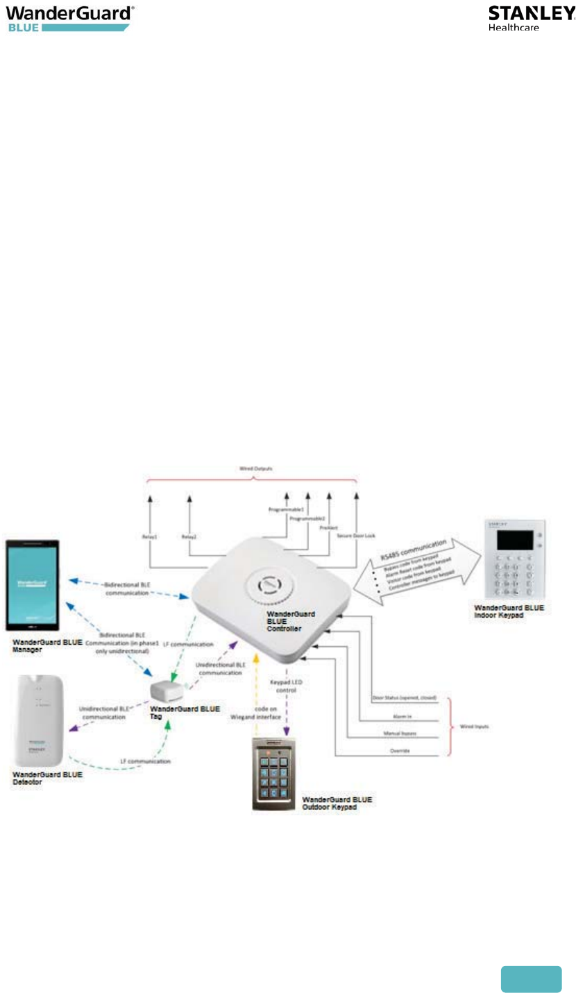
Architecture and Workflow
The basic system concept is that an alarm is issued and the door can be locked
when a resident Tag is within the Controller field. A Controller is typically
installed above a door and constantly transmits a signal in a certain frequency; a
resident Tag listens in that same frequency. When the Tag is "excited" by the
Controller signal (the Tag entered the Controller field), it sends a signal back to
the Controller in a different frequency. When the Controller receives the
message from the Tag, it can lock the door. The Controller can also be setup not
to lock/unlock the door when the Tag is in field. The Tag is non-supervised,
which means it transmits only when in range of the EX5700 Controller.
The WanderGuard BLUE Tag has a small form factor. Tags are available with
either a 90-day or 3-year battery life.
The EX5700 Controller controls the door lock via dedicated relay output. It has
additional relay output that is dedicated for siren control. It can be connected
to a Door Sensor from which it receives input on door status (open/closed). The
EX5700 has the following features:
x Configurable via the WanderGuard BLUE Manager
x Holds users credential information
x Switches between night and day modes per configured schedule
x Supports Indoor and Outdoor Keypads
User and Deployment Guide
13
If it is necessary to extend the EX5700 Controller LF range, for example, to
control two proximate doors by the same Controller, an additional EX5200
Exciter can be chained to the Controller using dedicated ports and a special
cable.
The WanderGuard BLUE Indoor Keypad receives power from the Controller.
Communication between the Controller and Indoor Keypad is by RS485. It has a
display that shows the mode of operation of the system and also reports events.
The Outdoor Keypad also receives its power from the Controller. It
communicates with the Controller via Wiegand output.
The WanderGuard BLUE Manager application is installed on an Asus tablet
(ZenPad 8 Z380M). The application can establish bi-directional BLE
communication with the Controller. The communication is used to configure the
Controller’s settings, day/night mode schedule, users’ credentials, and other
system properties.
The WanderGuard BLUE Detector is used for several activities:
x Tag activation
x Checking Tag battery level
x Supporting scanning for Tags by WanderGuard BLUE Manager

User and Deployment Guide
14
3
WanderGuard BLUE Tag
The WanderGuard BLUE Tag's function is to transmit messages to the Controller.
The Tag is triggered by signals from the Controller when it is in proximity to the
door. When the Tag message is received by the Controller, the Controller can
lock the door, preventing the resident from exiting the protected area. If the
door is open and the Tag is in proximity to the door, the system generates an
alarm.
The WanderGuard BLUE Tag is provided with a standard strap that can be worn
on an individual’s wrist or ankle. An optional cut-resistant WanderGuard BLUE
strap (Securaband™) is also available to provide a robust physical barrier to
unauthorized Tag removal.
Each WanderGuard BLUE Tag is identified by its own unique ID. The ID is can be
located on the side of the Tag.
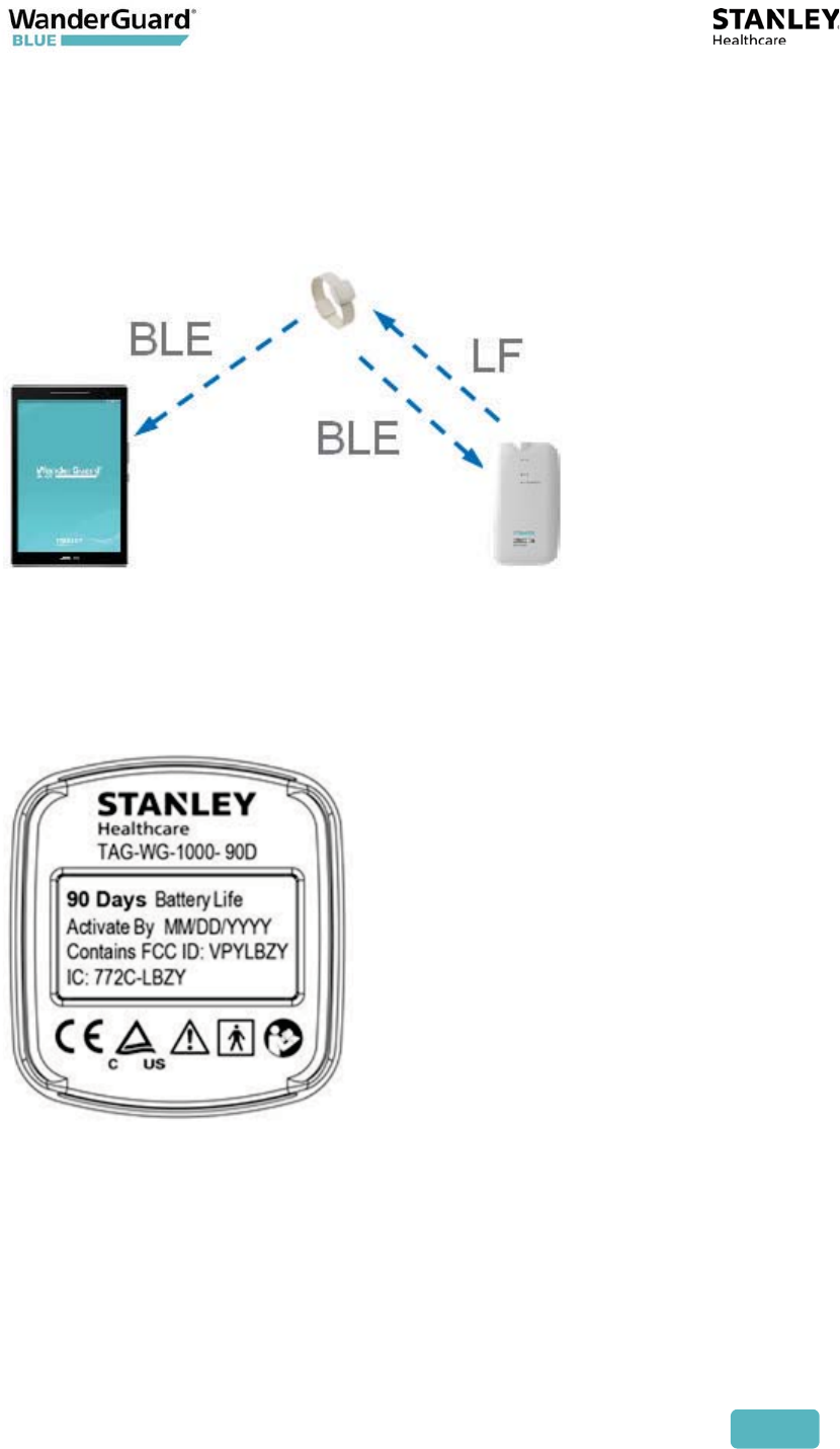
The WanderGuard BLUE Tag has a 125 kHz Low Frequency (LF) receiver. When
the Tag is within the Controller range, it receives LF signals transmitted by the
Controller's transmitter. The Tag then transmits 2.4 GHz BLE messages. The
messages are received by the Controller BLE receiver. Using LF ensures that the
adverse impact on Tag battery life is negligible.

User and Deployment Guide
15
WanderGuard BLUE Tag Battery Life
Two types of WanderGuard BLUE Tags are available:
x Ninety-day battery life
x Three-year battery life
Tag battery life can be tested by the WanderGuard BLUE Detector. It is
recommended to use the WanderGuard BLUE Detector to check the Tag battery
at least once a week.
Ninety-day Tag
The ninety-day Tag begins sending a Low battery message to the Detector two
weeks prior to the 90-day expiration date.
Three-year Tag
The three-year Tag indicates the low battery two months prior to the three-year
term.
Battery lifetime is guaranteed only if the Tag was activated prior to the
‘Activated By’ date listed on the back label.
WanderGuard BLUE Tag Communication
The WanderGuard BLUE Tag is initially activated by the WanderGuard BLUE
Detector (for activation instructions, see here in this User Guide).
Best Practice: It is recommended to perform Tag activation when the
Tag is out-of-range of the Controller and other Tags. It is OK for the Tag
to be in range of the WanderGuard BLUE Manager.
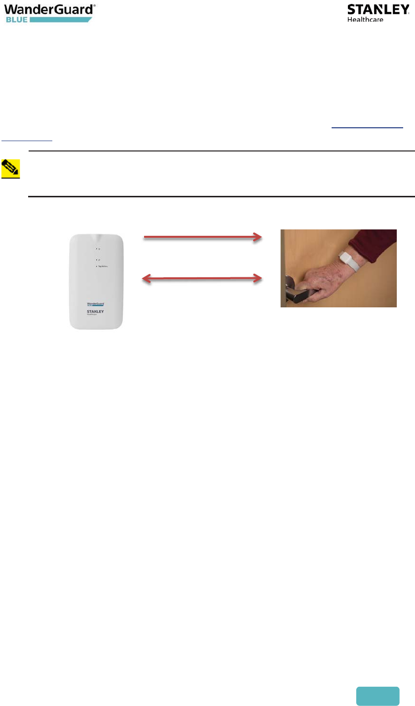
Tag Communication with the Detector
The WanderGuard BLUE Tag sends a BLE message with the following data when
it receives an LF message from the Detector:
x MAC ID
x Status – Dormant/Activated
x Firmware version
x Battery – Good/Low
x Battery Type – 90 days / 3 years
x Activation date
x Manufacturing Date
User and Deployment Guide
16
These Tag messages are received by both the Detector and the WanderGuard
BLUE Manager:
x The Tag information is displayed on the WanderGuard BLUE Manager when
running a "Scan" for Tags and Controllers.
x A Detector LED shows the battery status of the Tag.
Tag Back Label and Certifications
The label includes the Tag SKU, Type, and Activated By date. Tag compliance
and certification are also displayed.
User and Deployment Guide
17
Tag Delivery
The Tag is delivered with one (1) standard strap and the Tag User Guide.
If a heavy duty band is needed, Securaband straps can be used.
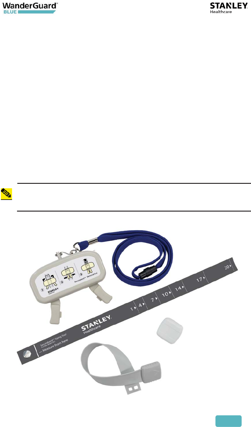
WanderGuard BLUE Securaband Starter Kit
A WanderGuard BLUE Securaband Starter Kit with a ruggedized cut-resistant
strap contains the following:
x WanderGuard BLUE Tag
x Sizing tool
x Removal tool
x WanderGuard BLUE Securaband strap – one (1) of each size
x Pocket Guide
x User Guide
Note
The following attachment, removal, cleaning and storing procedures are
applicable for the ruggedized cut-resistant Securaband strap for
WanderGuard BLUE Tags.
User and Deployment Guide
18
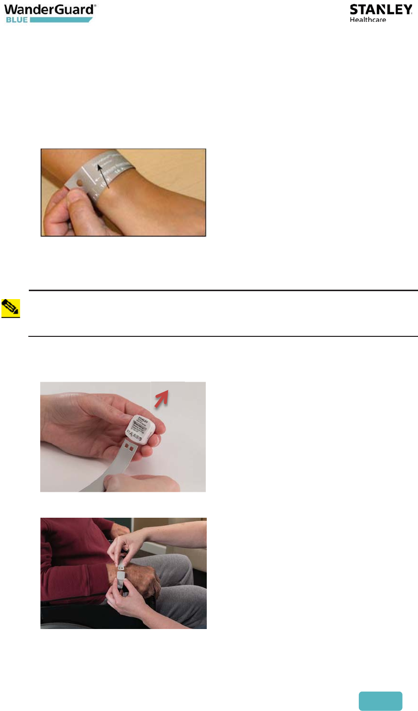
Attaching Tags
To attach the Tag:
1. To determine the strap size, wrap the sizing tool around the resident’s
wrist or ankle, making sure that the logo is facing you. The strap size is
the first number to the right of the measuring bar (in this example, size
10).
2. Select the appropriate WanderGuard BLUE strap from storage (the size is
printed on the box as well as on the inside of the strap).
Note
Measure carefully to ensure that the appropriate strap size is selected.
Once the strap has been attached, it cannot be used again.
3. Slide a WanderGuard BLUE Tag onto the strap, making sure that both
the serial number on the Tag and the size stamp on the strap are facing
you.
4. Position the strap around the resident’s wrist or ankle and insert the
free end of the strap into the clasp until it clicks into place.
5. Discard the sizing tool (it may be recycled but not used again).

User and Deployment Guide
19
Removing Tags
To remove the Tag:
1. Place the removal tool over the clasp, making sure that the chevron on
the clasp and the lanyard ring on the tool are facing in the same direction.
2. Squeeze the tool handles together to unlock the clasp.
3. While holding the tool handles together, pull the strap end out of the clasp.
4. Slide the Tag off the strap, clean and store the Tag, and discard the strap.
Cleaning Tags
Follow these recommendations for cleaning the Tag. WanderGuard BLUE straps
are single-use and cannot be re-attached.
x Use a mild soap and water to remove any apparent debris.
x Disinfect Tags by wiping with an alcohol sanitizer or germicidal cleaner for
60 seconds. Use only cleaners marked as safe for plastics. Tags are
incompatible with disinfectants containing Glycol Ether.
x Dry with a soft, clean cloth.
x Do not use an autoclave to clean Tags or serious damage may result.

User and Deployment Guide
20
WanderGuard BLUE Tag Specifications
Product Specification
Part Number SKU for Ninety-day Tag: WGB-TAG-1000-90D
SKU for Three-year Tag: WGB-TAG-1000-3Y
Model WGB-TAG-1000-90D
WGB-TAG-1000-3Y
LF Frequency 125 kHz
BLE Frequency 2400-2483.5 MHz
Battery Life
Options
Ninety days
Three years
Temperature 32° to 122°F (0 to 50°C)
Humidity 0-95% RH @ 70°F (21°C), non-condensing
Dimensions Approx. 1.08 x 1.16 x 0.6” (2.74 x 2.95 x 1.5 cm)
Weight Approximately 0.26 oz. (7.5 g)
WanderGuard BLUE Tag Disposal
At the end of its life, contact STANLEY Healthcare for instructions regarding Tag
disposal in accordance with Federal and other regulations governing this type of
device.

User and Deployment Guide
21
4
EX5700 Controller
The WanderGuard BLUE EX5700 Door Controller is a main component of
STANLEY Healthcare’s WanderGuard BLUE Wander Management Solution for
monitoring and securing facility doors against resident wandering. The
WanderGuard BLUE Door Controller controls the WanderGuard BLUE system by
receiving messages from Tags, Keypads, and the WanderGuard BLUE Manager
and can lock the door, as necessary. It also stores all system configuration
parameters.
The Controller is typically installed above or in proximity to the monitored door.
The Controller does the following:
x Controls the door lock
x Configured via WanderGuard BLUE Manager
x Holds user credentials data (up to 45 users)
x Switches between night and day mode per configured schedule
x Supports Indoor and Outdoor Keypads

User and Deployment Guide
22
Controller's Hardware Components
x One (1) LF (125 kHz) Transmitter
x One (1) BLE Receiver to receive messages from Tags
x One (1) BLE Transceiver for BLE communication with the WanderGuard BLUE
Manager
x Reset button
x Two (2) 2 A output relays
x Relay 1 – lock/unlock door
x Relay 2 – alarm annunciation
x 12 VDC power for Indoor/Outdoor Keypads
x External LF for additional Exciter/Antenna
x RS485 for Indoor Keypad
x Wiegand Input for Outdoor Keypad
x Real-time clock and battery
x Three (3) Grounds
x Four (4) 100mA output relays
x 1 - Secure Door Lock (Lock)
x 2 - Tag In Field (TIF) (preAlert)
x 3 - Programmable
x 4 - Programmable
x Four (4) inputs
x Door status
x Manual bypass (REX – request for exit)
x Override
x Alarm in
User and Deployment Guide
23
BLE Transceiver
x Sends BLE message every 3 seconds
x Used as a test mechanism for the BLE receiver:
x If the BLE receiver does not receive the message, it means that the
Receiver is not operating properly.
x This feature enables the Controller to monitor the Receiver that
communicates with the Tag. This test functionality prevents a situation
in which a resident could be without Tag protection due to a technical
problem without the staff knowing.
Clock
x Maximum drift of 400 msec a day
x Maximum drift of 1 minute in ~5 months period
x The clock has a battery that is used only when the Controller is not powered
up.
Best Practice: It is recommended to synchronize the Clock using the
WanderGuard BLUE Manager once every 6 months because of the Clock
drift.
User and Deployment Guide
24
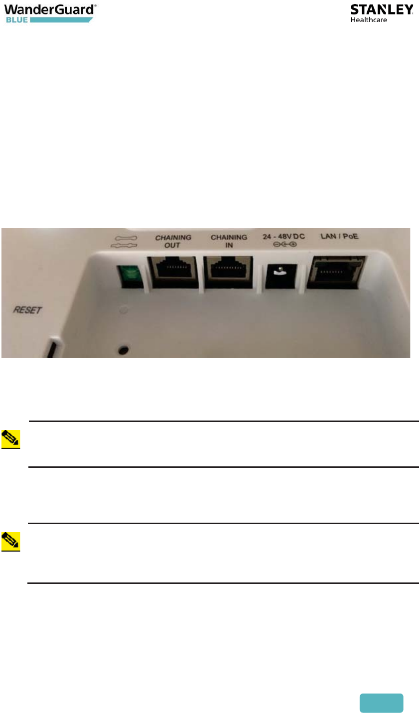
Rear Recessed Connection Panel
The back of the Controller contains a recessed connection panel for all EX5700
Controller connections including power and peripheral equipment (e.g., Indoor
Keypad, Outdoor Keypad, etc.) including:
x Cable Ports
x Reset Hole
x Wire Terminal Block
Cable Ports
LAN / PoE: RJ-45 connector. In a configuration with a physical Ethernet cable
connection to the LAN, the network cable is attached here.
Permanent connection to a wired network is not mandatory.
Note
PoE is currently not supported.
The EX5700 supports 100 Mb full-duplex communications. The Network Switch
must be configured to Auto Negotiation mode when connecting the Controller
to the Network Switch, in order to use the 100 Mb communications.
Note
When an Ethernet device is set to 100Mb/Full Duplex fixed, as in the
EX5700, and the switch port is set to auto-negotiate, then according to
the 802.3 standard, the communication from the switch side will be set to
100Mb/Half duplex.
24-48 VDC: Accepts an input voltage of 24-48 VDC. This is a standard 5 mm
(outer) 2.5 mm (internal) jack connector for direct power supply. The power
adapter is not supplied with the Controller and can be purchased separately.

User and Deployment Guide
25
(#3) CHAINING IN: Not supported.
CHAINING OUT: RJ-45 connector. This connector is used for distributing power
and data to chained Exciters or to connect an External LF Antenna. The output
voltage is 12 VDC (0.5 A maximum).
Termination Switch: Defining the termination settings in a chained Exciters
installation:
In regular chaining, the termination of the first and last Exciter in the chain
must be set to On (o-o) and the other Exciters set to Off (-o-o-).
The EX5700 Controller supports only being the first in a chain. The EX5700
cannot serve as a slave, e.g., the EX5700 cannot be chained to another EX5700.
Hence, the termination must be set to On (o-o).
Power Supply
The EX5700 Controller supports 24 V – 48 V power supply.
Product SKU
Power Supply 24 V US WGB-ADP-047-U
Power Supply 48 V US WGB-ADP-047-U
Power Supply 48 V Europe WGB-ADP-047-E
Power Supply 48 V UK WGB-ADP-047-UK
Altronix AL600ULM (UL294 central power supply) 80602001
Altronix AL175UL (UL294 central power supply) 15560
Altronix AL1024ULACMCB (UL294 central power
supply)
AGECP02-024
Note
It is prohibited to connect cables greater than 98.5 ft (30 m) long.
User and Deployment Guide
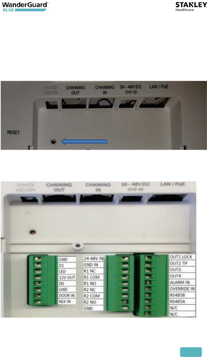
26
Reset Button
x Located in the back of the Controller, the label near the button is labeled
"Reset."
x Long press on the button (longer than 10 seconds) to restart and reset the
Controller with its default configuration.
x Short press on the button (shorter than 10 seconds) to restart the Controller;
the Controller keeps its current configuration.
Wire Terminal Block Description
The EX5700 Wire Terminal Block is accessed from the back of the Controller.

User and Deployment Guide
27
Connector Purpose Comment
OUT1 LOCK Follows Relay 1 Secure door lock. Follows
relay 1 (if relay 1 is
activated, the output is
activated)
OUT2 TIF Tag In Field
Activated when there is
Tag In Field.
OUT3 Programmable Output 3 Activated based on
configuration
OUT4 Programmable Output 4 Activated based on
configuration
ALARM IN Controller moves to Alarm mode Door is in Alarm mode
OVERRIDE IN Controller moves to Override
Mode
Door is in override
RS485B RS485 communication with
Indoor Keypad
RS485A RS485 communication with
Indoor Keypad
N/C Not connected For future use.
N/C Not connected For future use.
24-48 V IN Power IN. Accepts 24-48 V Direct
Current
Used if the 24-48 VDC
connector is not
connected. Connected to
external power supply.
GND IN Ground/Earth Used if the 24-48 VDC
connector is not
connected. Connected to
external power supply.
R1 NC Relay 1 normally closed
connection

User and Deployment Guide
28
Connector Purpose Comment
R1 COM Relay 1 common connection,
always connect Dedicated to Maglock
control. With internal
feedback control.
R1 NO Relay 1 normally open
connection Dedicated to Maglock
control. With internal
feedback control.
R2 NC Relay 2 normally closed
connection
R2 COM Relay 2 common connection,
always connect Dedicated to siren control.
With internal feedback
control.
R2 NO Relay 2 normally open
connection Dedicated to siren control.
With internal feedback
control.
GND Ground/Earth
GND Ground/Earth
D1 Wiegand Data 1 For Wiegand
communication with the
Outdoor Keypad
LED Indication of Wiegand interface For Outdoor Keypad
12 V OUT Power Used for powering Indoor
and Outdoor Keypads
D0 Wiegand Data 0 For Wiegand
communication with the
Outdoor Keypad
GND Ground/Earth
DOOR IN Door status Status on the door
(open/closed)
REX IN Request for exit Controller moves to Bypass
mode

User and Deployment Guide
29
Note
Connect to COM and NO if you want the switched circuit to be
on when the relay is on.
Connect to COM and NC if you want the switched circuit to be on
when the relay is off.
Connecting Programmable Outputs 3 and 4
The Controller has two programmable outputs. The outputs can be
programmed by the WanderGuard BLUE Manager to be activated when the
Controller enters a specific status/mode.
The outputs are automatically deactivated when the Controller is no longer in
that status/mode.
On the Controller's Terminal Block, the programmable outputs are designated
as follows:
x OUT3 on the Terminal Block – refers to programmable Output 3
x OUT4 on the Terminal Block – refers to programmable Output 4
Controller Modes and Relays
DAY MODE
x Relay 1 is activated upon TIF in order to lock the door
x Relay 1 returns to default upon TNIF
x After Bypass/Visitor code, Relay 1 gets deactivated
NIGHT MODE
x Relay 1 remains active during Night Mode
x Relay 2 gets activated when the door is opened. TIF is not necessary.
x Relay 2 returns to default when the Controller receives the reset code
x If Bypass/Visitor code is entered, Relay 2 remains in default for the
duration of the Bypass/Visitor Mode
x If Bypass/Visitor code is entered, Relay 1 is deactivated for the duration
of the Bypass/Visitor Mode

User and Deployment Guide
30
BYPASS MODE
x When the Bypass code is entered in the Keypad, Relay 1 is set to
deactivated state.
x When the Bypass code entered in the Keypad, Relay 2 is set to
deactivated state.
x During the Bypass period, multiple people (with or without Tags) are
allowed to walk through the door without any restriction.
x Bypass resets the alarm mode.
x Bypass is terminated if the door is not opened 5 seconds after the
Bypass code was entered.
x Within the Bypass time out period, Bypass is terminated after door is
closed.
x After Bypass time out:
x In night mode, if the door is opened, the Controller switches to
Alarm mode.
x In day mode, if the door is opened and there is TIF, the Controller
switches to Alarm mode.

User and Deployment Guide
31
VISITOR MODE
x When the Visitor code is entered in the Keypad, relay 1 is set to
deactivated state.
x When the Visitor code is entered in the Keypad, relay 2 is set to
deactivated state.
x Visitor mode uses the Bypass time out period.
x During the Bypass timeout period, multiple people without Tags
are allowed to walk through the door
x If there is TIF during Visitor mode and door is open, relay 2 is
activated.
x Visitor is terminated if the door is not opened 5 seconds after the
visitor code is entered.
x Within the Bypass time out period, Visitor mode is terminated after
the door is closed.
x After Bypass timeout:
x In Night Mode, if the door is opened, the Controller switches to
Alarm Mode
xIn Day Mode, if the door is opened and there is TIF, the Controller
switches to Alarm Mode
x Visitor code does not reset the alarm.
xIf ‘alarm in’ or TIF, the Controller switches to Visitor Mode when the
Visitor code is entered and relay 1 gets deactivated.

User and Deployment Guide
32
ALARM MODE
x When not in Night Mode, Relay 2 gets activated when the door is
opened and there is TIF.
x When in Night Mode, Relay 2 gets activated when the door is opened.
x Relay 2 returns to default when the Controller receives Reset or Bypass
code from the Keypad.
x After Reset:
x In Night Mode, if the door is opened, the Controller switches back
to Alarm Mode.
x In Day Mode, if the door is opened and there is TIF, the Controller
switches to Alarm mode.
ALARM RESET
x Reset code returns Relay 2 to its default setting (pending door status).
x Reset code returns Relay 1 to its default setting (pending door status).
x If there is an alarm condition (e.g., Night Mode with open door, open
door and TIF), the alarm reset does not reset the alarm.
x If there is "Alarm In", the alarm Reset resets it.
OVERRIDE MODE
x Relays 1 and 2 are deactivated.
xLF transmission is disabled.
x Any person with or without Tags can go through the door during the
Override period.
User and Deployment Guide
33
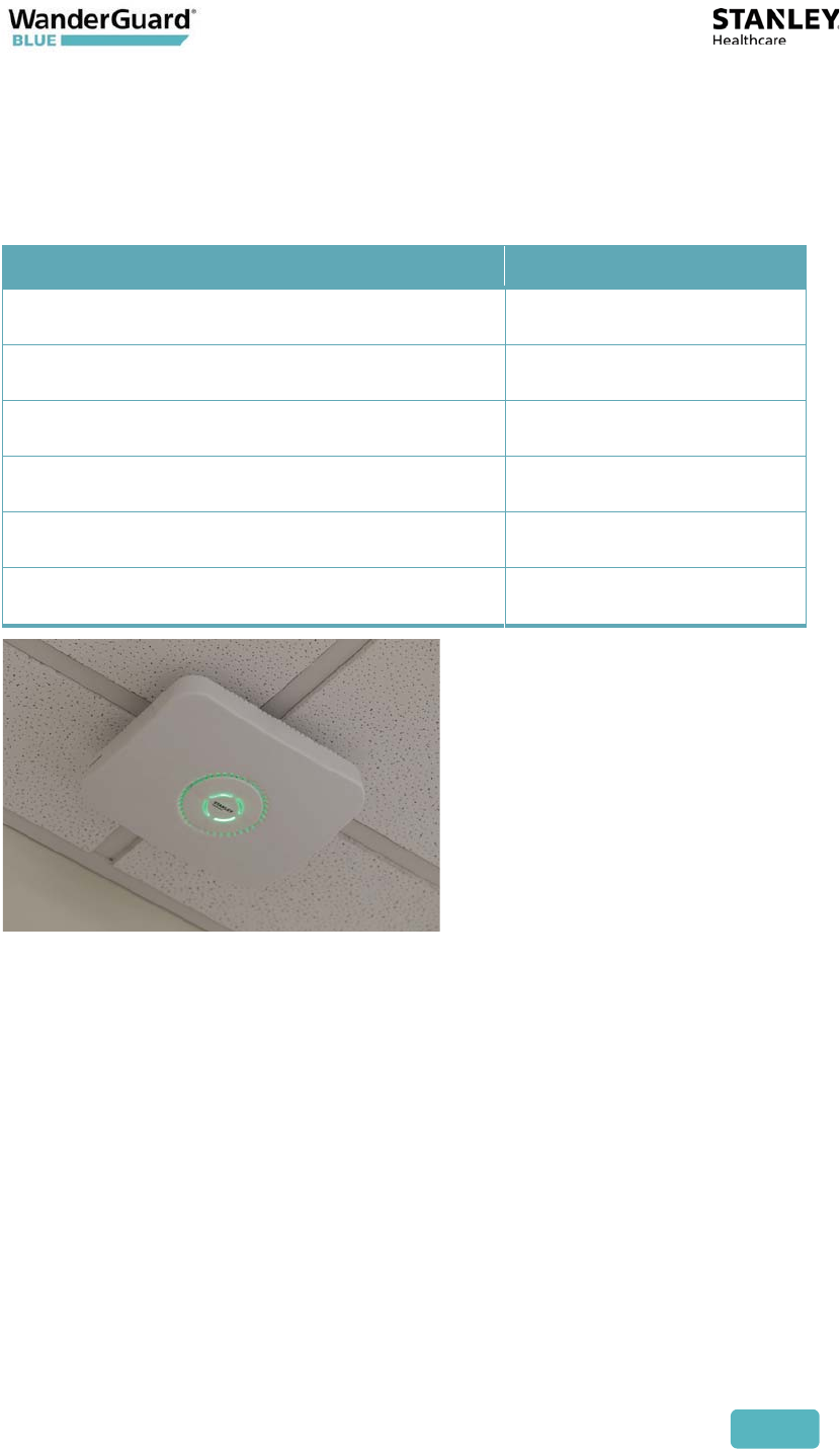
Controller LED Status Indicators
The Controller LEDs show Controller status as follows:
Color Status
Solid Green Ready – Day Mode
Solid Red Ready – Night Mode
Blinking Green Override
Blinking Red Alarm
Solid Amber Error
Blinking Amber (3 sec) Blink command
LEDs are displayed according to the following priorities:
x Error supersedes Alarm.
x Override supersedes Alarm and/or Error.
x Blink supersedes Override, Alarm, and/or Error.
User and Deployment Guide
34
External LF Antenna (ANT4200)
An External LF Antenna connection is supported for the EX5700 Controller to
extend LF range.
The External Antenna Unit (ANT4200) supports one Mode:
x Same ID as the Controller – the External Antenna's function is a range
extender.
If an External LF Antenna (ANT4200) is connected to the Door Controller as a
range extender, the internal LF and External LF Antennae transmit
simultaneously.
The External LF range can be configured via the WanderGuard BLUE Manager
between 0.25 m to 3 m in steps of 0.25 m (default 3 m). External LF can be
configured even when Internal LF is disabled.
For External LF Antenna mounting instructions, see the External LF Antenna
Installation Guide (KB Article 8380).

User and Deployment Guide
35
Slave Exciter
A Slave Exciter can be connected to the EX5700 Controller. The Slave Exciter
allows extension of the LF range in the case of double doors or proximate door
that is controlled by the same EX5700 Controller as follows:
Exciter EX3210
x LF Exciter with 3 meters range
x Connected to the Controller via Cat5 cable
x Up to 3 Exciters can be chained with a single Controller power supply
EX5200 Exciter
x LF Exciter with 6.5 meters range
x Connected to the Controller via Cat5 cable
x Up to 2 Exciters can be chained with a single Controller power supply
User and Deployment Guide
36
Configuring the Slave Exciter
The Slave Exciter cannot be configured by the WanderGuard BLUE Manager. It
needs to be configured by the Local Engine. The configuration includes:
x Setting the LF range of the Exciter.
x Setting the Exciter to the Slave Exciter.
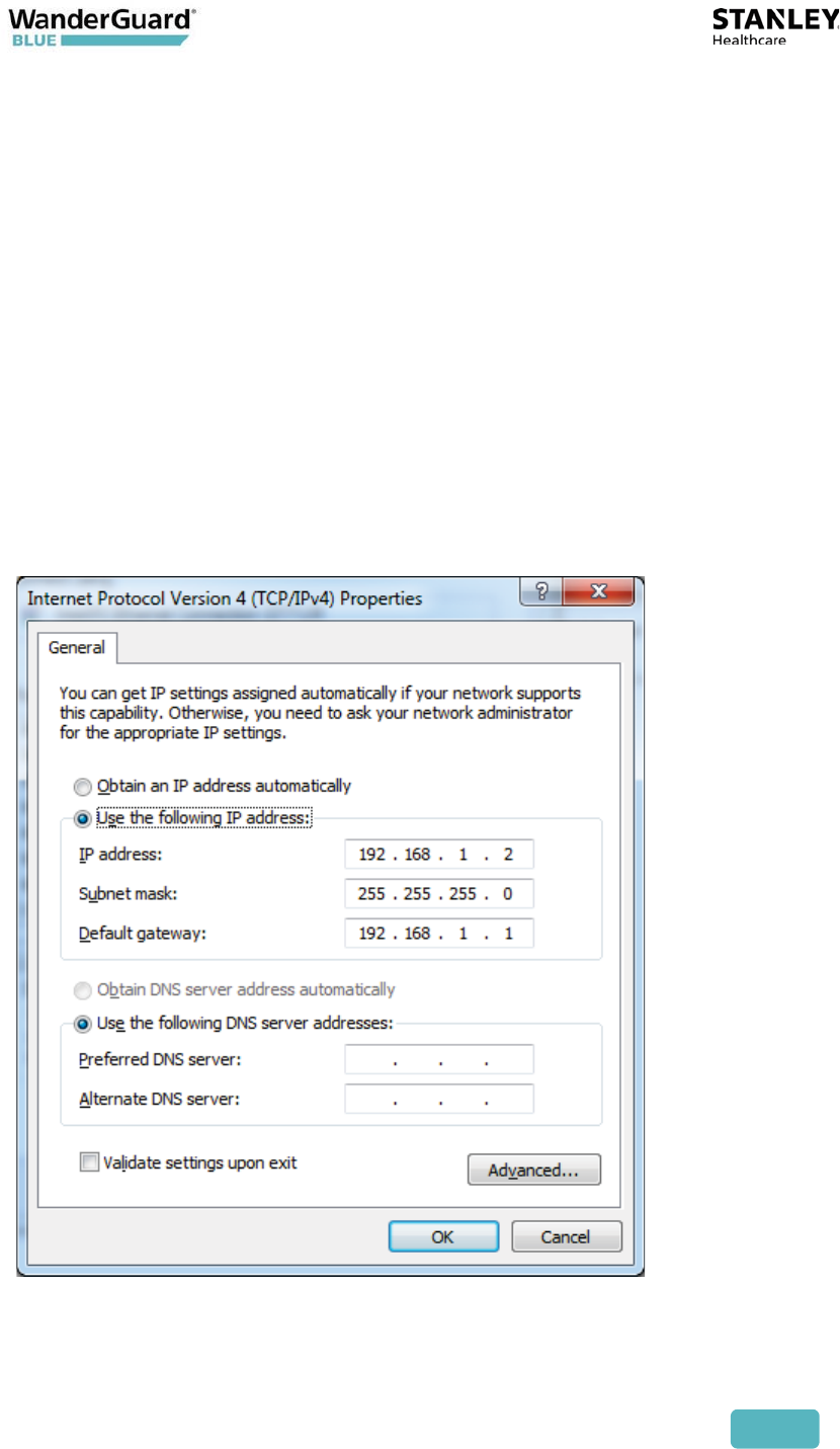
Do the following to configure the Slave Exciter:
1. Set the PC with AeroScout Location Engine:
x Install Engine 5.0 SP4 Manager and Server (Non-Cisco Platform).
x Connect the PC to the ‘LAN’ Connection of the Exciter.
x Set the PC to have static IP of the same subnet as the Exciter.
x The Exciter default IP address is 192.168.1.178.
User and Deployment Guide
37
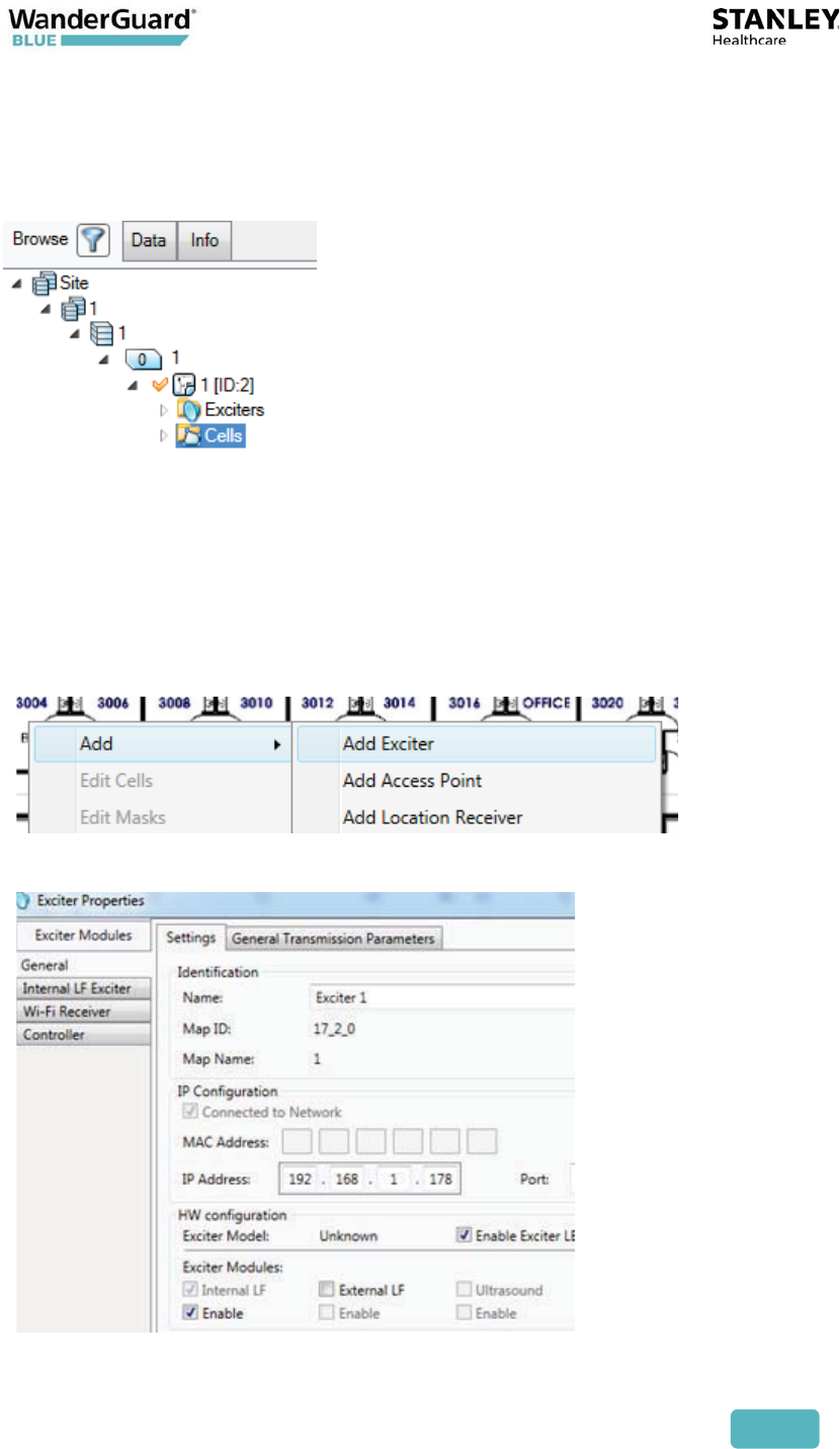
2. Configure the Engine:
x Launch Engine Manager, and connect to the Engine server.
x Configure basic settings (add Campus, Building, Floor and Map).
3. Add the LF Exciter to the Engine:
x Add the Exciter to the Engine configuration.
x Set the Exciter’s IP to 192.168.1.178.
x The Controller should appear online in ~1 minute.
User and Deployment Guide
38
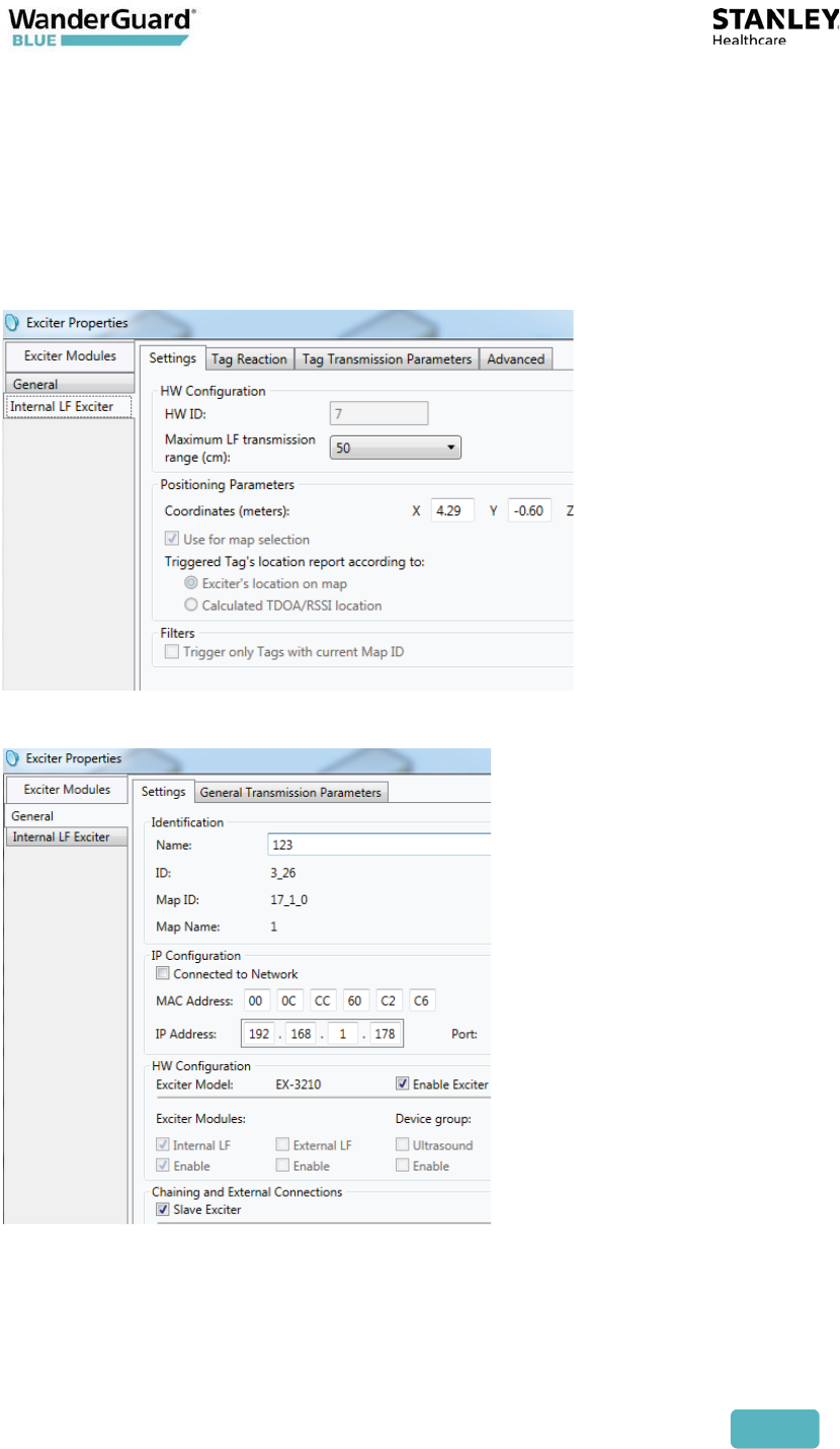
4. Set the Exciter's Properties:
x Open the Exciter Properties.
x Set the LF transmission Range.
x Set the Exciter as slave Exciter.
x Click OK.

User and Deployment Guide
39
Configuration of the Slave Exciter:
1. The EX5700 is defined as the “Master.” Other Exciters are designated
“Slave.”
2. The Master Controller is connected to the first Slave Exciter as follows:
Master Chain OUT to Slave Chain IN.
3. Slave Exciters are then connected as follows: Slave OUT to Slave IN.
4. The Termination Switch of the Master and the last Slave Exciter in the chain
must be set to On (o-o).
On the other Slave Exciters, it must be set to OFF (-o o-).
For more information on Slave Exciter configuration and mounting, see the
EX3210 and EX5200 deployment guides here.
Mounting the EX5700 Controller
For standard mounting with standard mounting and heavy-duty mounting kits,
see Appendix A.
For mounting using the Controller Wall-mount Bracket, see Appendix B.
User and Deployment Guide
40
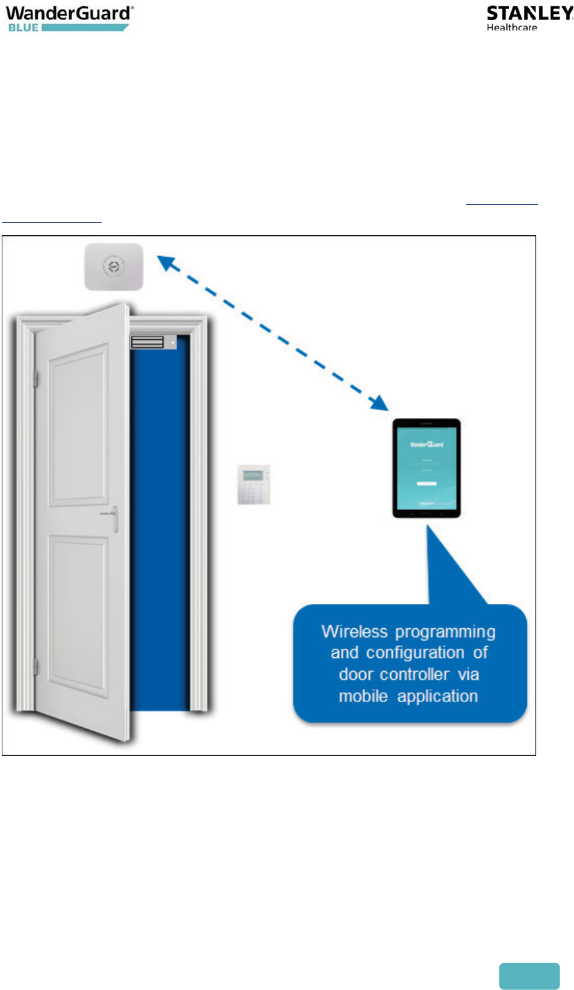
WanderGuard BLUE Manager
Bi-directional BLE communication between the WanderGuard BLUE Manager
and the Door Controller can be established from the mobile application. After
establishing communication, the EX5700 Controller configuration can be set
using the WanderGuard BLUE Manager.
To configure the Controller via WanderGuard BLUE Manager see Controller
Configuration in this User Guide.

User and Deployment Guide
41
Integration with Arial
Integration with Arial is supported in WanderGuard BLUE v1.0 by connecting
Inovonics transmitter(s) to the Controller’s relays or outputs.
Integration via Inovonics 54350:
x Can be connected to dry contact (Relay 1 or Relay 2 – for example to NO and
COM)
x Transmits an Alarm when 12 VDC is sent
x Sends a clear message when the 12 VDC is removed
x 54350 can also be used for output activation:
x Transmits an Alarm when the 100 mA output is activated
x Sends a clear message when the 100 mA output is deactivated
Integration via Inovonics 14390:
x Can be connected to 12 V relay and to 100 mA output (the 12 V can come
from the Controller)
x Transmits an Alarm when the 100 mA output is activated
x Sends a clear message when the 100 mA output is deactivated
User and Deployment Guide
42
EX5700 Controller Firmware Upgrade
Controller firmware upgrade involves the following steps:
x Setting up the PC from which the Controller firmware upgrade is performed
and installing the AeroScout Location Engine (ALE)
x Configuring the AeroScout Location Engine
x Adding the Controller to the Engine configuration
x Performing the upgrade
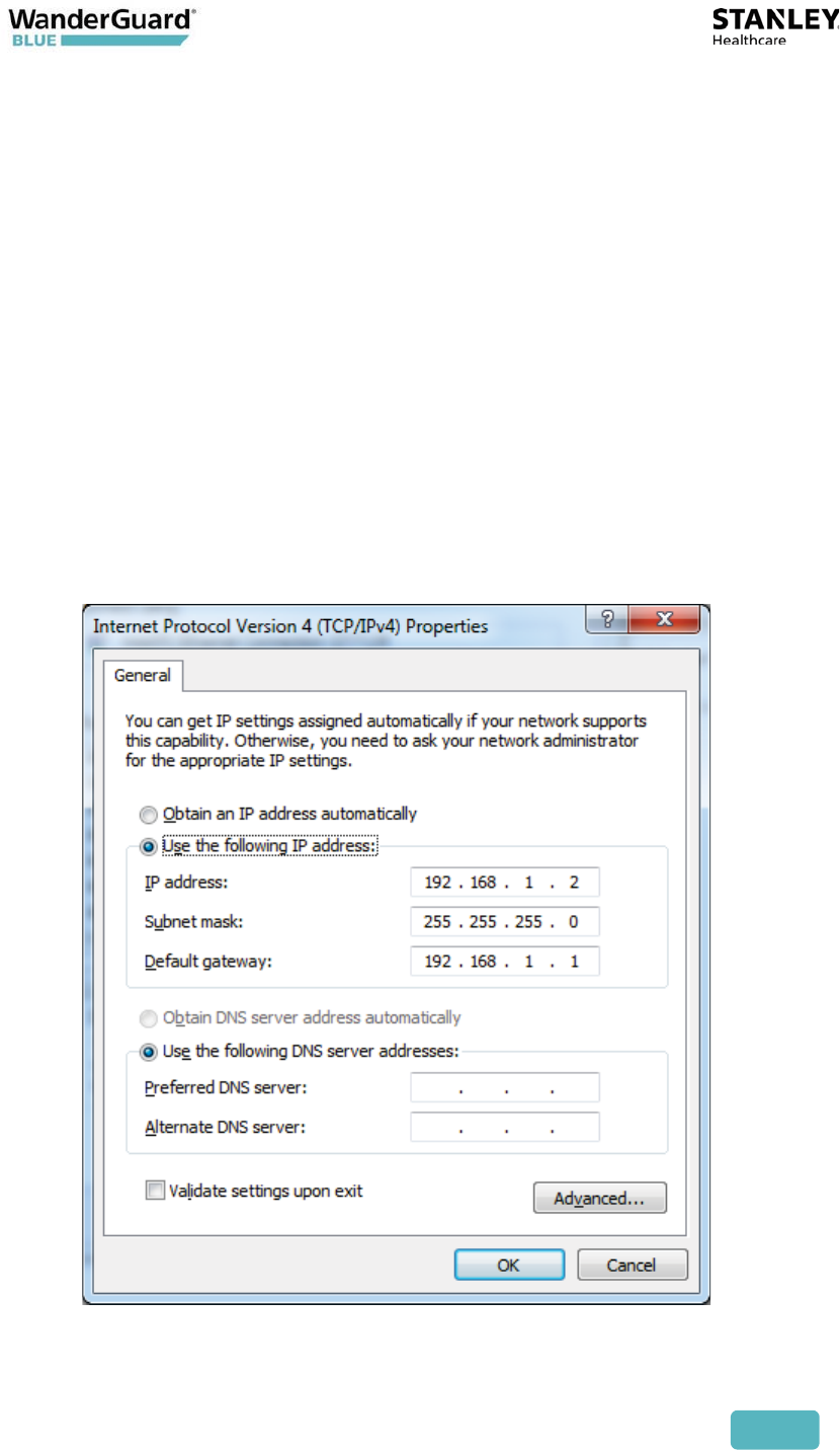
Setting up the PC
1. Install Engine 5.0 SP4 Manager and Server (non-Cisco platform).
2. Connect the PC-to-LAN connector of the Controller.
3. Set the PC to static IP in the same subnet as the Controller. The
Controller default IP address is: 192.168.1.178.
User and Deployment Guide
43
Configuring the Engine
1. Launch Engine Manager, and connect to the Engine Server.
2. Configure the basic settings (add Campus, Building, Floor and Map).
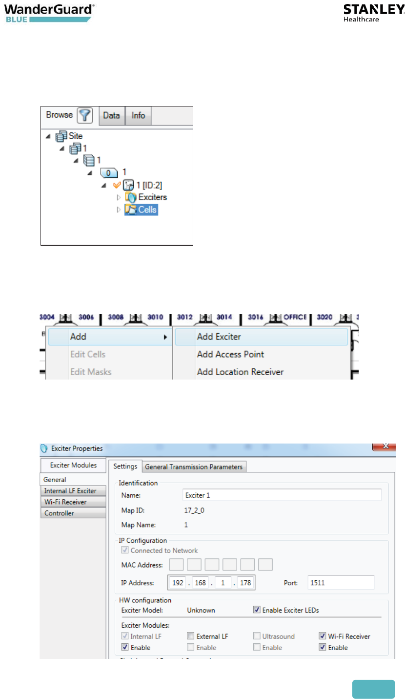
Adding the Controller
1. Add the Exciter to the Engine configuration.
2. Set the Exciter with Wi-Fi Receiver enabled.
3. Set the Controller's IP to 192.168.1.178.
4. The Controller appears online after approximately one minute.
User and Deployment Guide
44
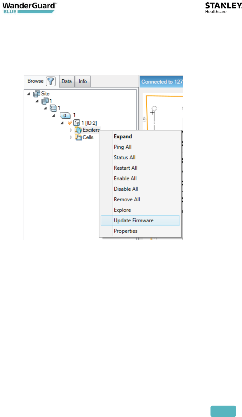
Upgrading the Firmware
1. Open the Upload Firmware dialog from the Exciter by right-clicking the
Exciter folder.
2. Select "EX5700" in the Model drop-down window.
3. Browse to the firmware file of the EX5700.
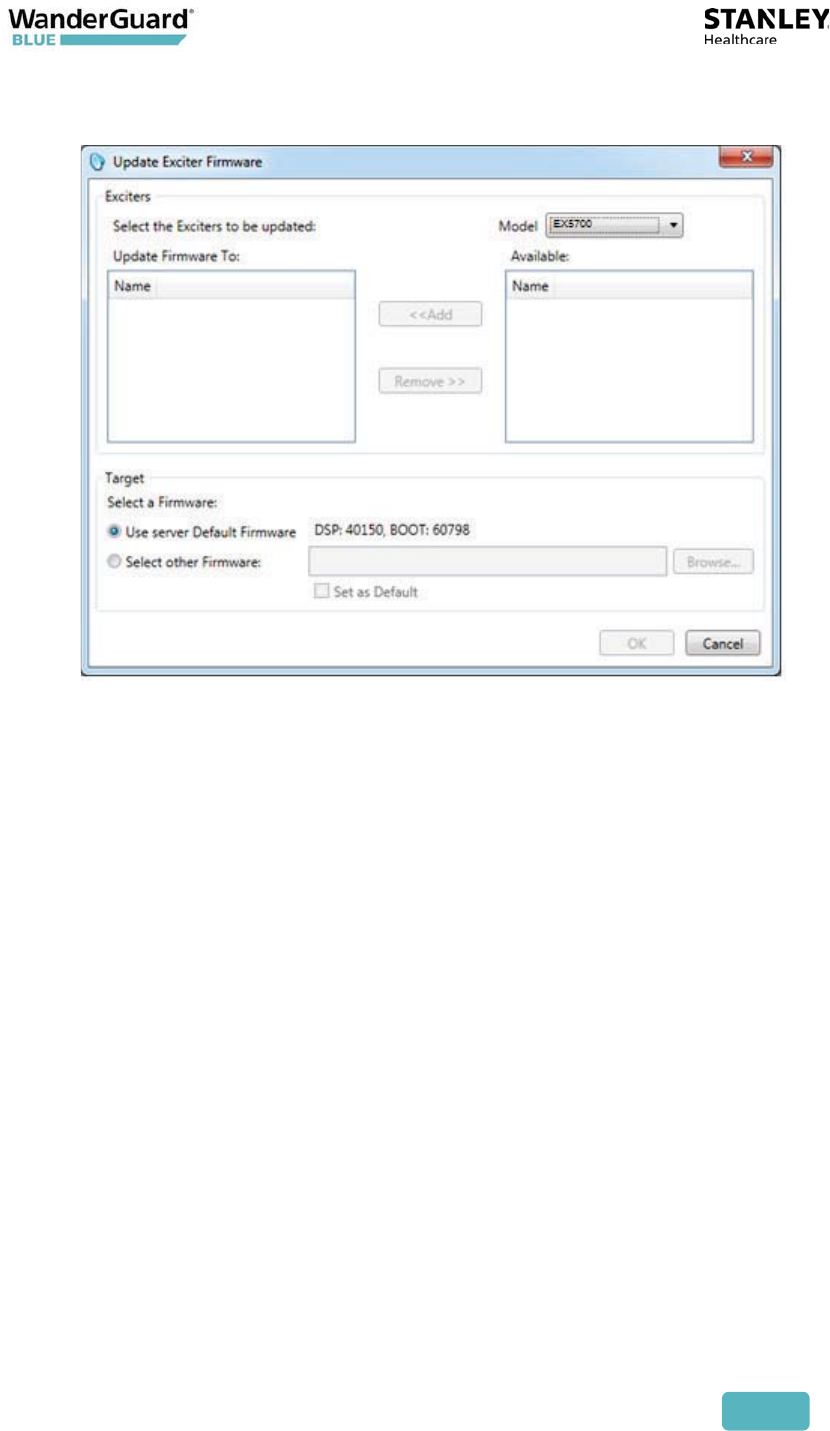
User and Deployment Guide
45
4. Add the Controller to "Update Firmware To."
5. Click OK to begin the upgrade.
6. The upgrade takes approximately four minutes.

User and Deployment Guide
46
EX5700 Controller Specifications
Product Specifications
Part Number SKU: EX-5700-NA, EX-5700-E
Dimensions 245 mm X 200 mm X 60 mm (9.6in x 7.9in x 2.4in)
Weight 865g (31oz)
Housing Polycarbonate and ABS
Range Adjustable from 0.5m (20in) up to 6.5m (21.3ft) in
intervals of 0.5m (20in)
LF channels 125 kHz Field intensity limits: 37.3dBȝA/m at 10m (ETSI)
Propagation limits: 21.8 dBȝV/m at 300m (FCC)
Modulation: ASK
Power Input voltage 24-48 VDC 48 VDC
Maximum power consumption: 8 W Maximum power
consumption of External LF Antenna: 5 W
Environmental Operating temperature: 0 to 50°C (32°F to 122°F)
Humidity: 0 to 95%, non-condensing
Certification FCC Part 15, sub-part C class B, sub-part B EN 300-330
EN 301.489 RSS210 (Canada) EMC IEC60601-1-2
(Europe) Safety: CE, cTUVus (EN60950)
Relays Two: max. switching voltage 220 VDC/250 ACD, max.
switching power 30 W/62.5 VA, max. switching current
1A, NO (Normally Open) or NC (Normally Closed)
Operational Notes:
x The Controller needs to be used as described in this section.
x The Controller should not be maintained and/or serviced while in use
x The Controller should be installed and mounted as explained in this
document
x Power supply should be used per the power requirement of the Controller
x If not installed and mounted, the Controller should be stored in the
designated box it is shipped with.
x Cleaning the Controller should be done only when it is not connected to
power.

User and Deployment Guide
47
Symbols in the Back label:
x Safety 60950
x Safety 60601
x Compliance with the WEEE (Waste Electrical and Electronic Equipment)
Directive
x Approved by FCC
x Approved for sale in Europe
x Double insulated electrical appliance
User and Deployment Guide
48
5
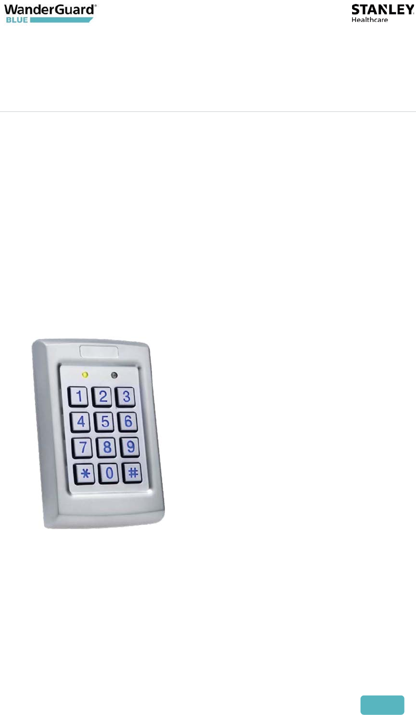
Indoor Keypad
The Indoor Keypad is used to control the door by entering commands on the
keypad. The Indoor Keypad displays Controller Status – Alarm, Bypass, Day
mode, Override, Error, etc. It also displays system events such as Alarm, Door
Ajar, and Loitering. A PIN code can be entered to unlock the door or reset an
alarm.
User and Deployment Guide
49
Overview
The Indoor Keypad does the following:
x Connects to EX5700 via RS485
x Powered (12 V) by the Controller
x Displays the Controller’s status/mode on its screen
x Displays Controller Error(s) on its screen
x Uses LEDs to indicate Controller status
x Can use its built-in buzzer to indicate alarms and events
x Sends the entered key to the Controller for verification
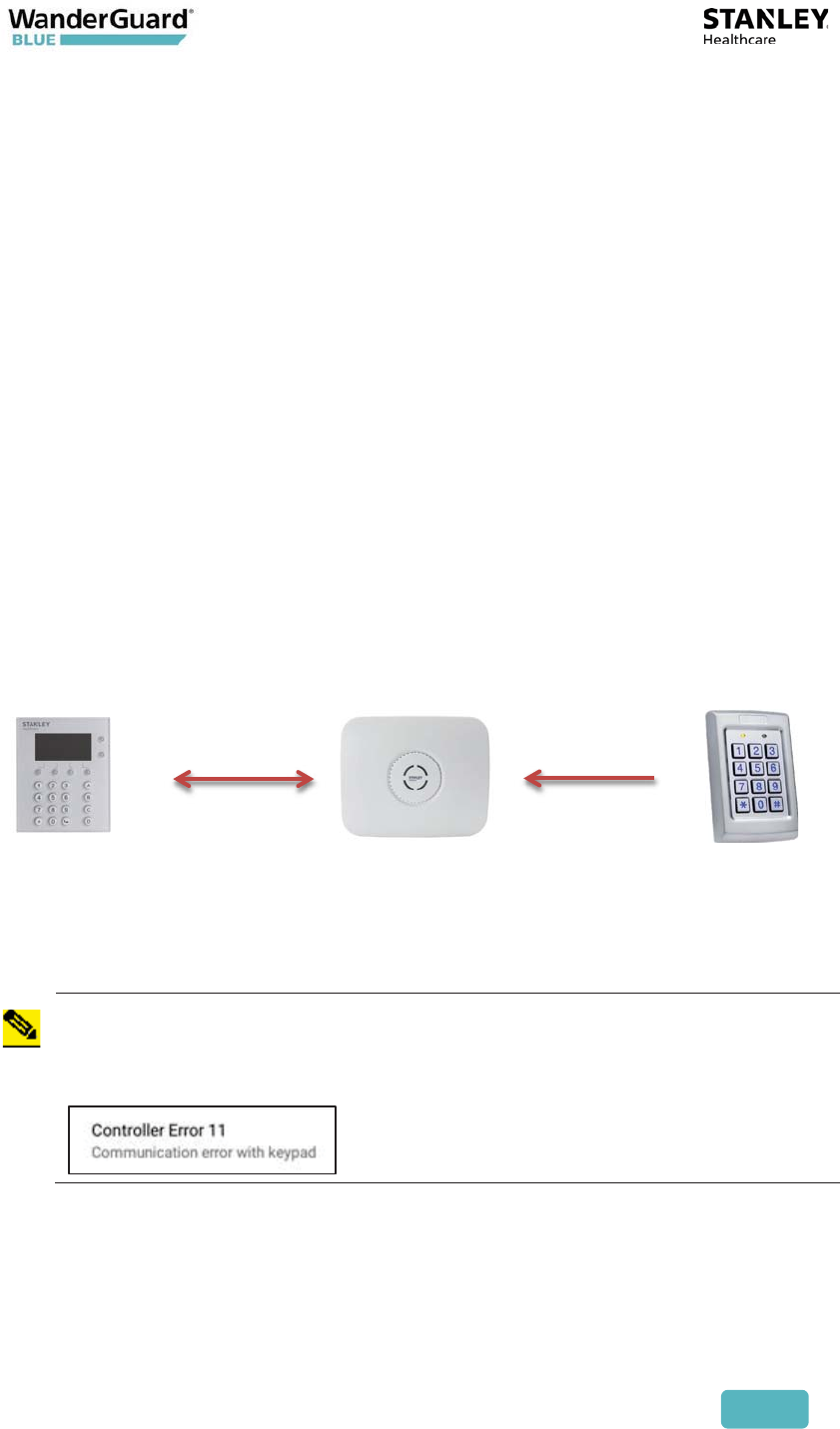
Wired Connections
The Indoor Keypad is physically connected to the Controller via RS485. The
Outdoor Keypad can be simultaneously connected to the Controller via
Wiegand.
Both Keypads are powered by the Controller (12 V).
Indoor
Keypad
RS-485 Controller Wiegand Outdoor
Keypad
Note
If only an Outdoor Keypad is connected to the Controller (an Indoor
Keypad is NOT connected), then an error is issued by the Controller. The
Controller's LED color changes to Amber, and an error message is
displayed in the WanderGuard BLUE Manager mobile application:
User and Deployment Guide
50
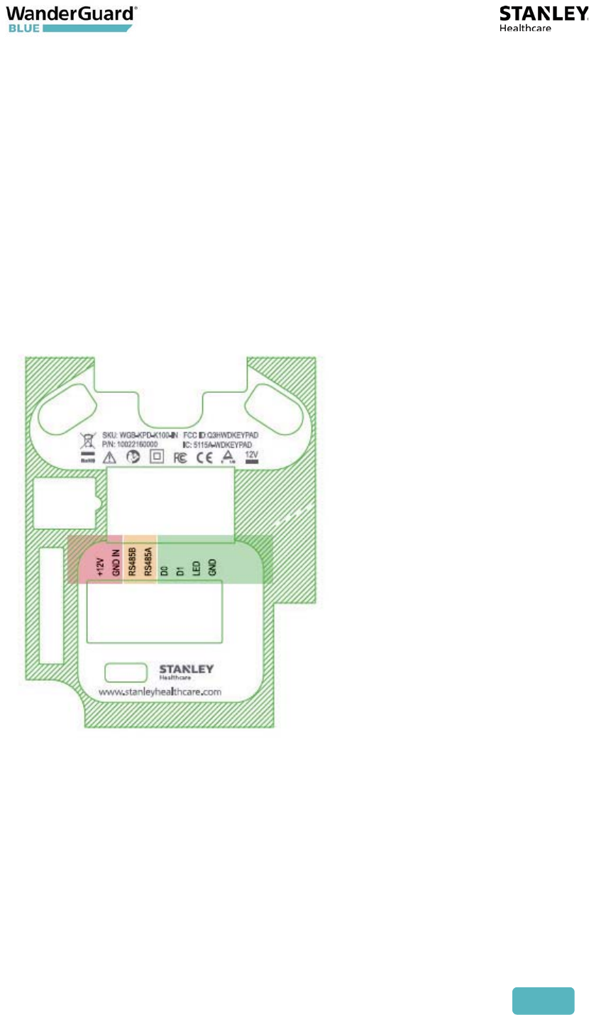
Communication
Power
x 12 V from the Controller to +12 V
x GND from the Controller to GND IN
RS485
x RS485A from the Controller to RS485A
x RS485B from the Controller to RS485B
Wiegand input from a reader (D0, D1, LED, GND) is intended for future use of a
reader that can be connected to the Keypad.
User and Deployment Guide
51
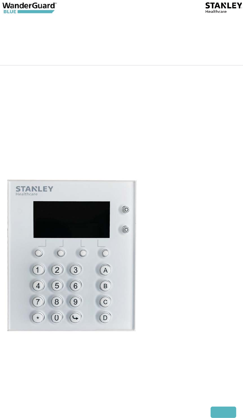
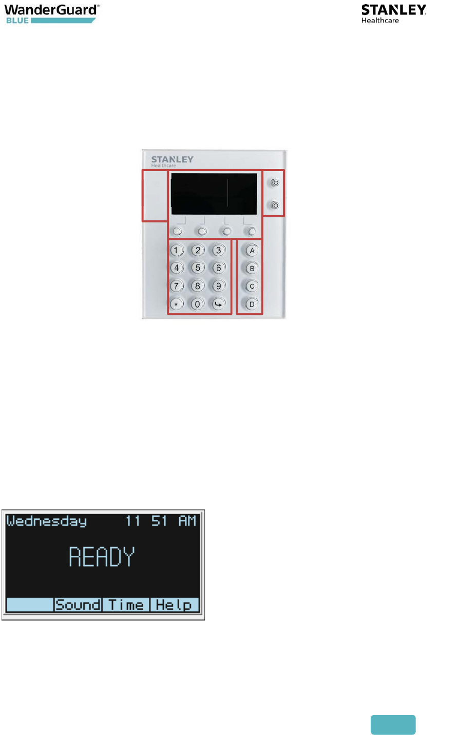
Buttons and LED Display
The buttons below the screen are used to enter a code or activate a menu item
displayed on the Keypad screen (the two buttons to the right of the LED screen
are intended for future use).
x The main Keypad consists of 3X4 keys: the numbers 1 – 9 and a bottom row:
*, 0, #.
x A vertical column on the right side contains the Function Keys: A – D.
x Below the LED screen are buttons that activate the displayed LED screen
menu item.
x To the right of the LED screen are two buttons. These buttons are intended
for future use.
x On the left side of the LED screen is the power LED. The LED is Green when
power is ON and blinks RED when there is an alarm. Another LED below it is
reserved for future use.
The following is the typical main screen of the Indoor Keypad:
Main keypad
Power LED For future use
Screen navigation buttons
Function buttons
User and Deployment Guide
52
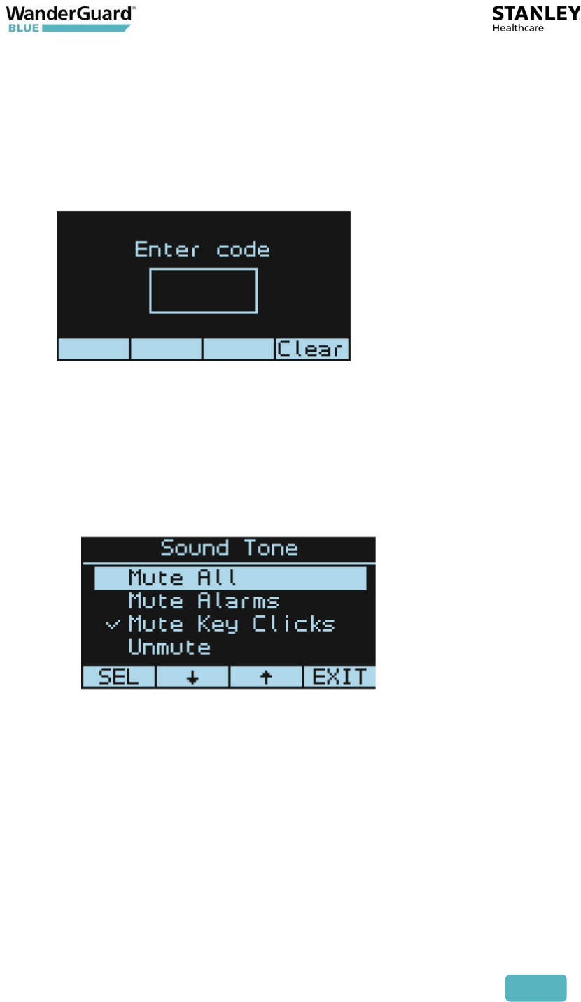
Mute/Unmute Indoor Keypad Sounds
The Indoor Keypad is used to toggle the door buzzer on/off.
To Mute/Unmute Indoor Keypad sounds:
1. Press the Keypad button below Sound on the screen. The following
screen opens.
2. Code (2020*) is required to be entered to modify Sound settings
The following options are displayed:
x Mute All – mute Key clicks and events sound
x Mute Alarms – mute Alarm, Door Ajar, and Loitering events sound.
x Mute Key Clicks – mute Key Click only
x Unmute
3. Click SEL to select your choice. Verify that your choice is "checked."
4. Click EXIT to return to the main screen.
User and Deployment Guide
53
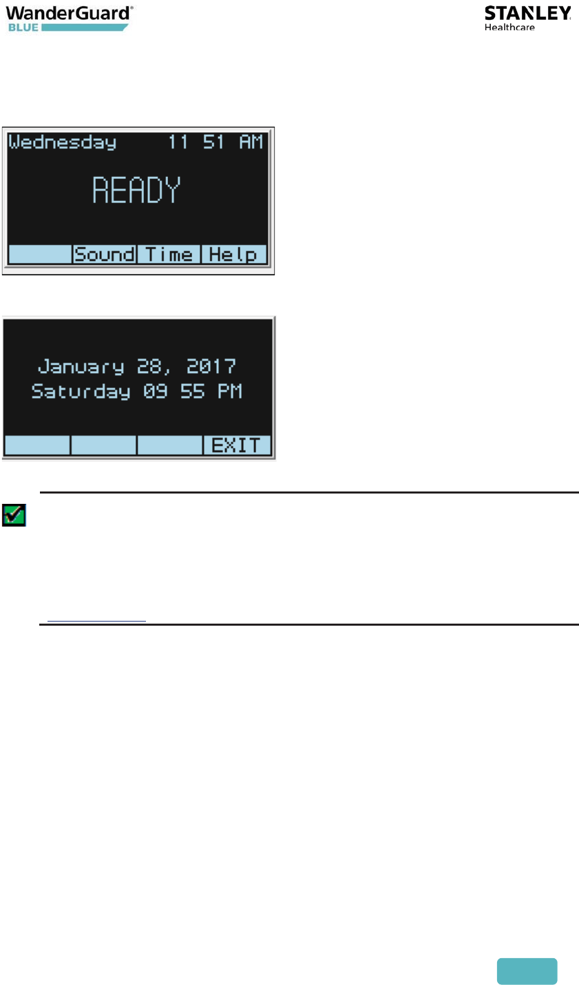
Time
To view the current time, press Time on the main screen.
The following screen opens:
Best Practice: When the system is initially installed at the customer site,
the Indoor Keypad shows a default date of January 3, 2017. When the
Indoor Keypad downloads its time settings from the Controller, it begins
showing the same time settings as the Controller. The Input Keypad date
and time are changed by modifying the appropriate Controller fields
within the WanderGuard BLUE Manager mobile application. See the
Clock Settings page of the WanderGuard BLUE Manager.

User and Deployment Guide
54
Help
The Help screen displays the Keypad Software Version and provides access to
the Function Buttons menu.
To access the Function Buttons menu:
1. Click Help.
2. In the screen that opens, click Function Buttons:
3. Click SEL to select (it's the only option).
4. The Function Buttons selection screens opens. See Function Button
Options.
User and Deployment Guide
55
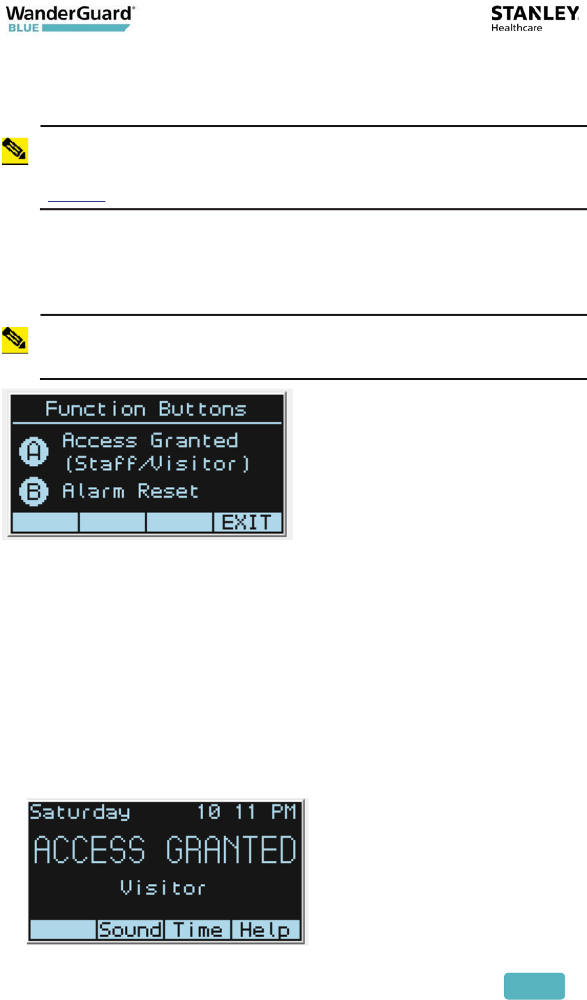
Function Button Options
Note
The Visitor and Bypass codes and the time period that the door is open
can be changed in the WanderGuard BLUE Manager. The Alarm Reset
code can also be changed in the WanderGuard BLUE Manager. See
Settings in the Controller Configuration chapter of this User Guide.
Function buttons activate the designated function (Access Granted, Alarm Reset)
after the preset PIN code is entered by a staff member on the Indoor Keypad.
These functions are accessed by keying in the numerical code and then pressing
the designated Letter button (A or B) on the Keypad.
Note
The C and D buttons are reserved for future use.
Function Button A – Access Granted
This function is used together with the Visitor Code or Bypass Code to open the
door. The following are the default codes:
Bypass code – 0000A
Visitor code – 0001A
Entering one of these codes opens the door, and the Indoor Keypad
simultaneously displays an Access Granted message. The Access Granted
function stays active for the designated time period (the default time period is
five seconds).
x Access Granted (Visitor)
User and Deployment Guide
56
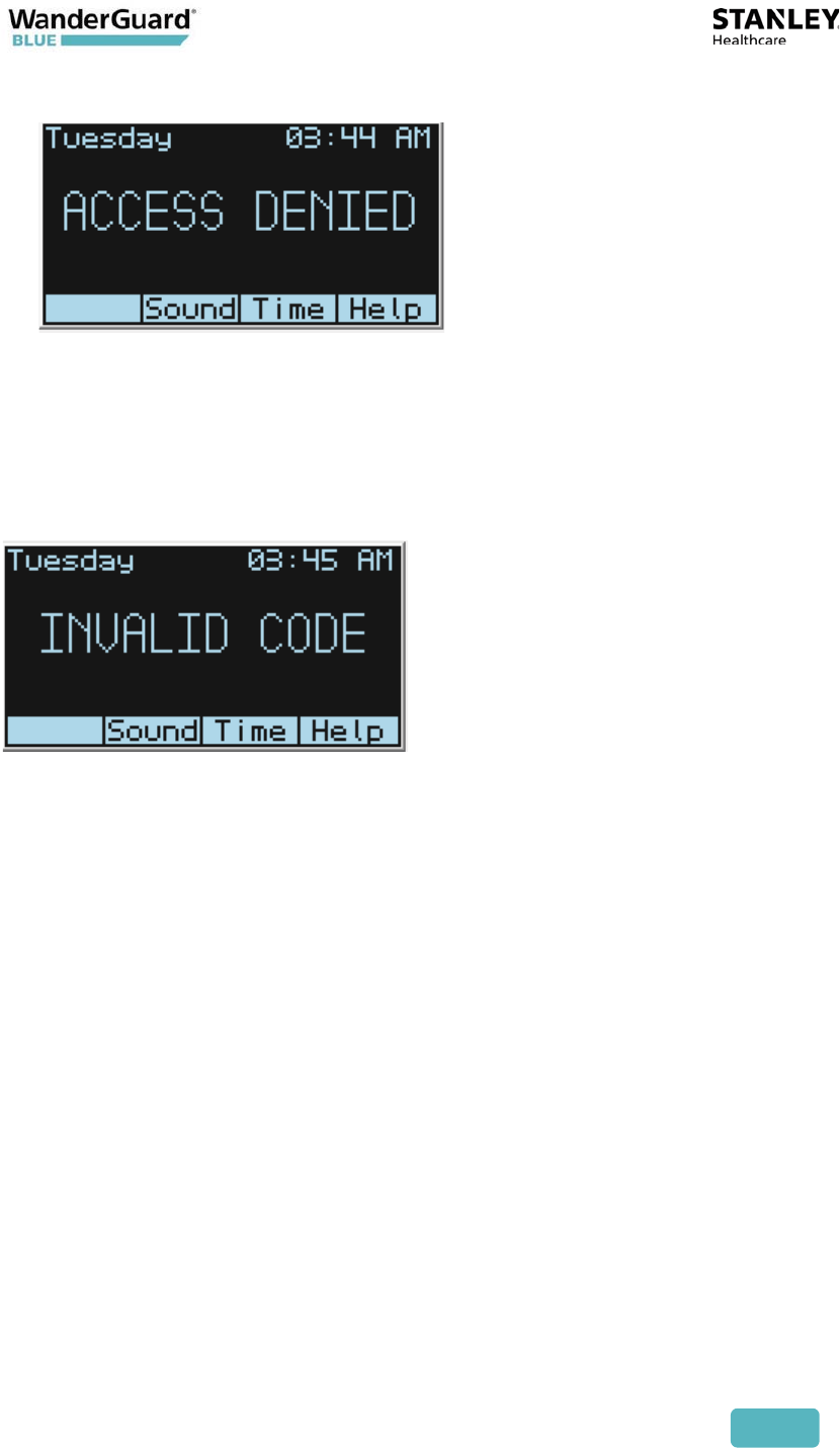
x An "Access Denied" message is issued when the code is invalid
Function Button B – Alarm Reset
This function is used to turn off the alarm (9999 + function Button "B") and
return the Indoor Keypad to its READY state. An alarm is issued, for example, if
the door was opened without proper authority.
If a wrong code is entered, an Invalid Code message is displayed:
Function Button C
For future use.
Function Button D
For future use.
User and Deployment Guide
57
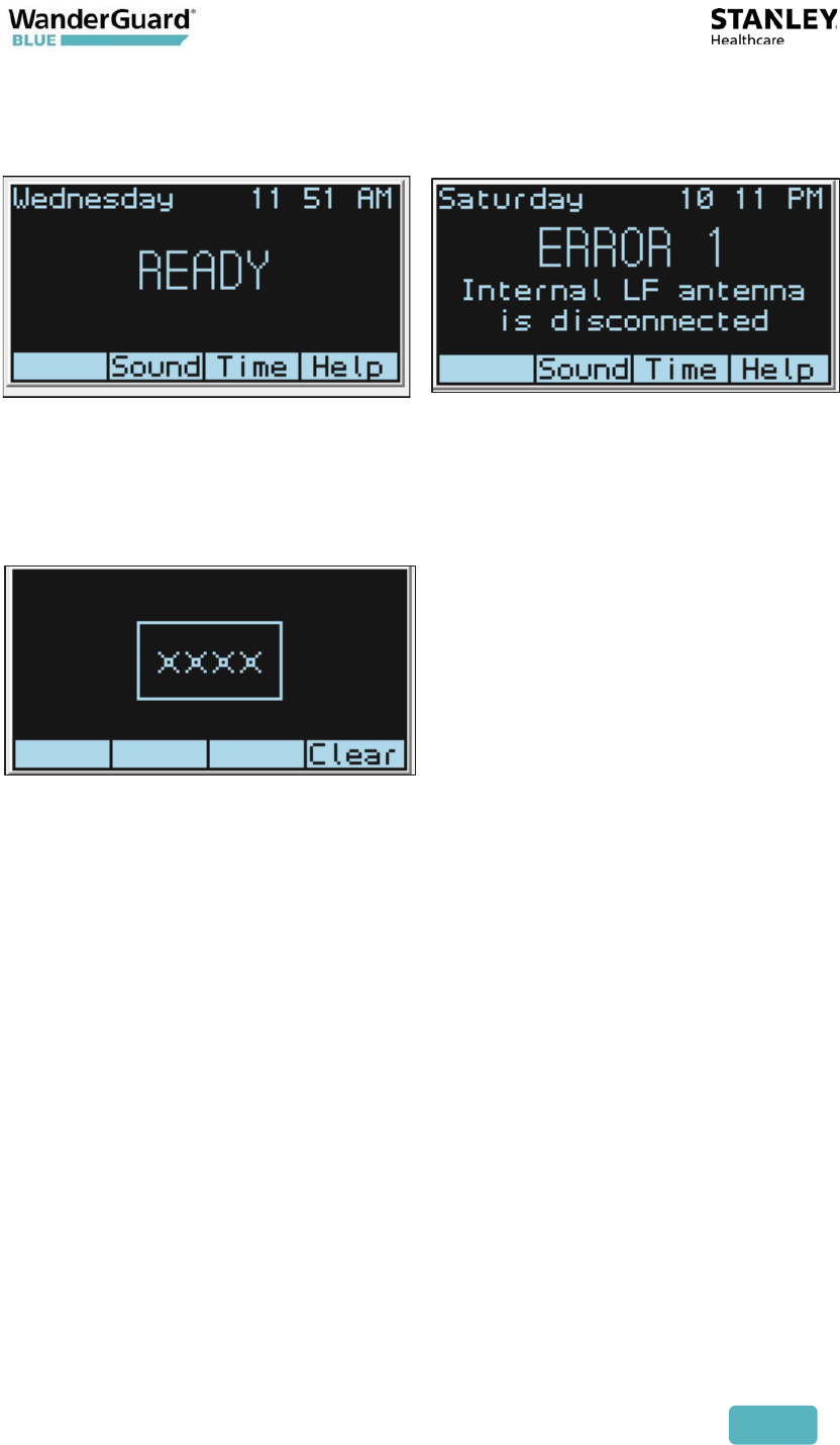
Keypad Display
Time and Day of the Week are displayed on the upper row of the LED display.
The display shows the mode/status of the Controller and indicates any
Controller error such as a communication failure with the Controller.
If you make a mistake during code entry, press Clear to start over.
Indoor Keypad statuses:
x Ready
x Ready – Night Mode
x Door Ajar
x Loitering
x Override
x Access Granted (Visitor)
x Access Granted (Staff)
x Access Denied
x Invalid Code
x Alarm
x Controller Error
x Communication Failure

User and Deployment Guide
58
Keypad LEDs
The Indoor Keypad has two left-side LEDs (looking at the Keypad): a lower LED
and an upper LED.
The lower shows errors and loss of communication. The upper shows Status and
Mode. The following are the color codes:
Display Upper LED (Ready / Alarm)
Ready Solid Green
Ready – Night Move Solid Red
Override Blinking Green
Bypass Solid Green
Visitor Solid Green
Alarm Mode Blinking Red
Loitering Solid Green
Door Ajar Solid Green
Access Denied Solid Green
Invalid Code Solid Green
Error Off
User and Deployment Guide
59
Indoor Keypad Firmware Upgrade
A PC application is used to upgrade the Indoor Keypad firmware.
The following are firmware upgrade preliminary steps:
x Install the application on the PC
x Install the driver for the micro-USB
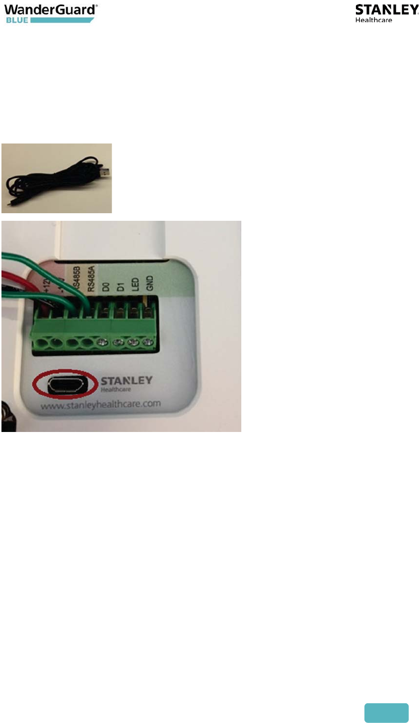
Connect the PC to the Indoor Keypad by the micro-USB connector at the back
panel of the Keypad using the dedicated cable. The cable SKU is:
WGB-UPCAB-KPD-1000.
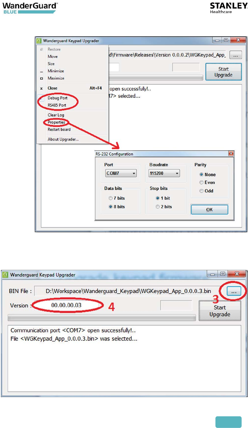
Do the following to upgrade the Indoor Keypad firmware:
1. Open the application and from the main menu, select the following type
of connection: Debug port
2. From the Properties menu, select virtual Com port (the adapter creates
virtual COM-port on the PC). The following communication needs to be
defined:
x Baud-rate 115200
x 8 data bits
x 1 stop bit
User and Deployment Guide
60
x No parity
3. Select the binary file for upgrade.
4. If the file name is defined in correct format, the version number is
automatically detected; if not, you need to define new version number.
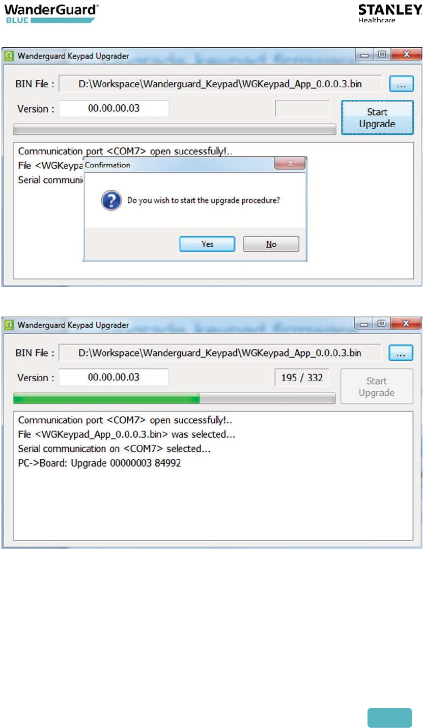
5. Press the Start Upgrade button and Yes to start the upgrade.
User and Deployment Guide
61
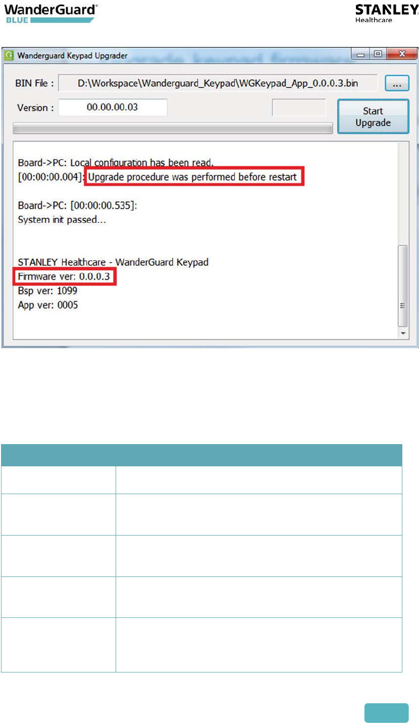
6. A progress bar and counter appear showing the status of the upgrade.
7. After the upgrade is completed, information regarding the upgrade and
new firmware version number is displayed in the log window.
User and Deployment Guide
62
Indoor Keypad Specifications
Specifications
Part Number SKU: WGB-KPD-K100-IN
Operating
Voltage Range
11.5 to 15 VDC from a standard Controller
Input Current Standby: 50 mA at 12 VDC
Maximum: 200 mA at 12 VDC
Communication
with Controller
RS485
Keypad 3x4 keys standard arrangement; 4-digit PIN codes
entry
Backlight blue keys

User and Deployment Guide
63
Specifications
Design Enclosure suitable for indoor use
Audio/Visual Graphical LCD: 128x64 + white backlight
Buzzer for audio indication/alert ~90dB@10cm
Tri-color indication LEDs: red, green, yellow
Pin Code Format Numerical 4-digit length PIN codes
Environment Operating temperature: 0°C to 50°C (32°F to 122°F)
Storage temperature: -20°C to 50°C (-4°F to 122°F)
Operating Humidity: 0 to 95%, non-condensing
Physical Dimensions: L104 mm x W22.5 mm x H125 mm
(L 4.1 in. x W 0.89 in. x L 4.92 in.)
Weight: 206 g (0.54 lbs.)
User and Deployment Guide
64
6
Outdoor Keypad
The Outdoor Keypad is Rosslare Security's AYC-Q54B. It sends Wiegand output
to the Controller after a code is entered. The 4 digit code does not need any
other keys to be entered. Verification of the code is done by the Controller.
These codes include:
x Bypass code
x Visitor code
x Alarm Reset code
The Outdoor Keypad:
x Receives 12 V power from the EX5700 Controller
x Communicates WITH the EX5700 Controller via Wiegand
x UL294-certified

User and Deployment Guide
65
Door Opening Using the Outdoor Keypad
The same numerical codes apply to both the Outdoor Keypad and Indoor
Keypad, except that there are no Function Buttons (A, B) when using the
Outdoor Keypad.
Since there is no A or B key in the Outdoor Keypad, it is sufficient to enter only
the numerical code.
To open the door using the Outdoor Keypad:
1. Enter the appropriate code at the Outdoor Keypad.
2. As you key in the numbers, the LED blinks from red to green.
3. After the fourth digit is entered, the LED changes to green, and the
door is unlocked.
4. After the door is relocked (when the door closes), the LED changes color
from green back to red.

User and Deployment Guide
66
Outdoor Keypad Specifications
ELECTRICAL SPECIFICATIONS
Reader mode: 5 to 16 VDC from a standard Controller
Controller mode: PS-x25T series intelligent power supplies
Standby: 65 mA at 12 VDC
Maximum: 110 mA at 16 VDC
Tamper: Optical back tamper sensor, O.C. active low, 32 mA max. sink
current
Operational Specifications
Keypad: 3x4 keys for local programming and 4- to 8-digit PIN codes entry
Design:
Epoxy potted, fully-sealed in a rugged metal enclosure; blue backlit metal
keys, highly strong construction.
Suitable for extremely harsh environments.
Audio/Visual: Two tri-color LED indicators, built-in buzzer
Environmental Specifications
Operating Environment: All weather, indoor and outdoor use, meets IP65
Operating Temperature: -35°C to 66°C (-31°F to 151°F)
Operating Humidity: 0 to 95% (non-condensing)
Physical Specifications
Dimensions: 120 x 76 x 21 mm (4.72 x 3 x 0.83 in.)
Weight: 480 g (1.05 lbs.)

User and Deployment Guide
67
Standalone Outdoor Keypad
A standalone Outdoor Keypad is not part of the WanderGuard BLUE solution
but can be used with it. Unlike the Outdoor Keypad, this Keypad does not have
Wiegand output.
x International Electronics Inc. (IEI) 0232142- REV 3
x SKU: 15615
x Same output Keypad as used with RoamAlert (for maglocked doors).
x Can be connected to the Controller via the REX input.
x PIN codes can be entered into the Keypad to open the door.
x PIN codes need to be programmed in the Keypad.
x The Standalone Outdoor Keypad is usually connected directly to the door
(the door is unlocked when PIN code is verified by the Keypad).
User and Deployment Guide
68
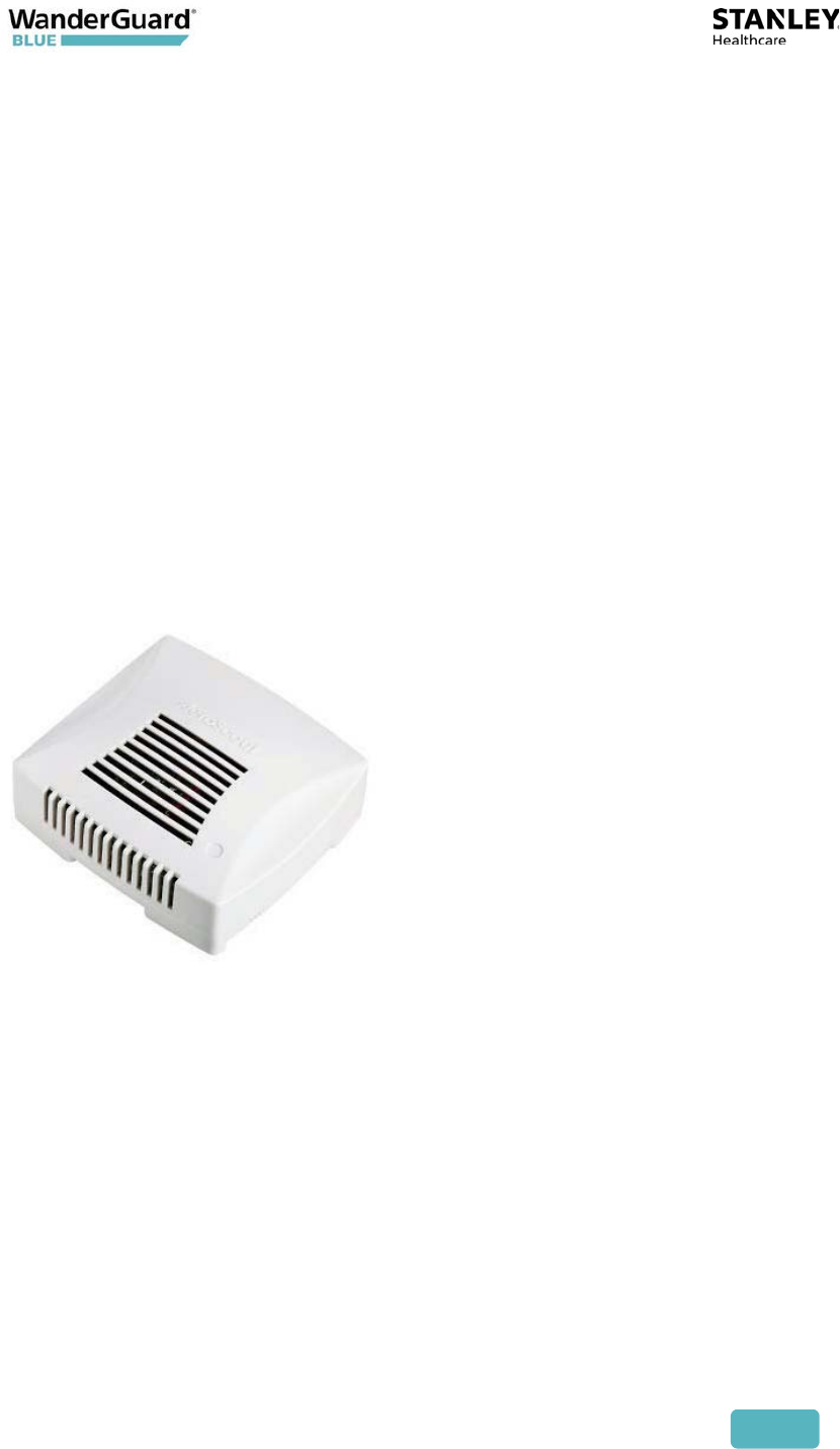
7
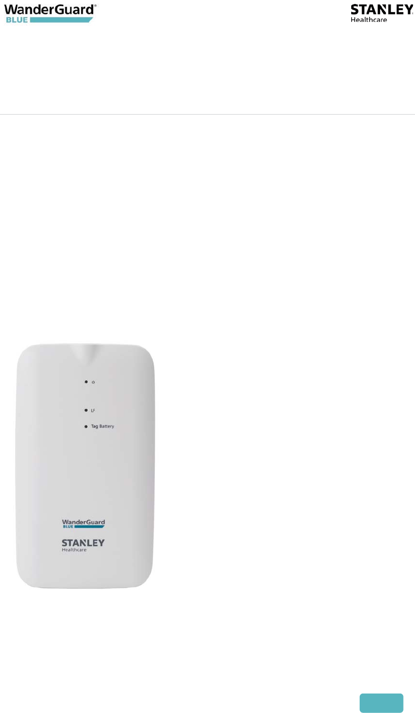
WanderGuard BLUE Detector
The WanderGuard BLUE Detector is a component of STANLEY Healthcare’s
WanderGuard BLUE Wander Management Solution.
This portable hand-held device is used to perform the following activities:
x Tag activation
x Checking Tag battery level
x Support WanderGuard BLUE Manager's scanning for Tags

User and Deployment Guide
69
Physical Characteristics
The WanderGuard BLUE Detector is equipped with the following:
x 3 LEDs
x Side button (ON/OFF)
x Micro-USB connector
x Power charger
x Lanyard
Turning a WanderGuard BLUE Detector ON and OFF
To turn ON a WanderGuard BLUE Detector:
1. Short-click the power button.
2. The Power LED turns ON (Ivory color).
To turn OFF a WanderGuard BLUE Detector:
1. Press the power button for 1 second.
2. The Power LED turns OFF.
The WanderGuard BLUE Detector goes into Sleep Mode 10 minutes after startup
if not in use (to save its battery life). When in Sleep mode, the Detector needs to
be powered up in order to work.

User and Deployment Guide
70
LEDs
Power Indicators
On Ivory
Off Power LED is OFF
Low battery Ivory (blinking)
Charging Red
Fully charged Green
Battery Indicators
Tag with ‘Good’ battery level Green for two seconds
Tag with ‘Low’ battery level Red for two seconds
Receiving BLE messages from
more than one Tag
Ivory for two seconds
LF Indicators
When LF is transmitted Ivory color blinking for 0.25 second
When receiving a BLE message
from an activated Tag
Green for two seconds
When receiving BLE messages
from more than one Tag
Ivory for two seconds
USB Connector
The USB Connector with power adaptor is used to connect the WanderGuard
BLUE Detector to a power outlet. Alternatively, the cable can be connected to a
PC -USB port.
User and Deployment Guide
71
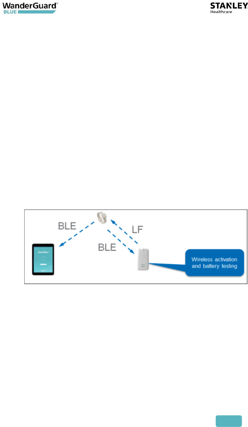
Communication
The Detector communicates only with the Tag. The Detector transmits LF
messages to the Tag every two seconds within a range of 0.3 - 0.5 m. It also
receives BLE messages from the WanderGuard BLUE Tag (see the WanderGuard
BLUE Tag chapter).
Note
The Detector does not transmit/receive when it is charging.
The Detector does not directly connect to WanderGuard BLUE Manager.
LF
BLE
User and Deployment Guide
72
Activating a WanderGuard BLUE Tag with the
Detector
To activate a WanderGuard BLUE Tag with your Detector:
1. Turn on WanderGuard BLUE Detector by short-clicking the power
button.
2. Place a WanderGuard BLUE Tag within the Detector's LF range (less than
0.5 meter).
3. Activate the Tag – press the power button for 1.5 seconds.
x Detector sends activation message via LF.
x Detector beeps to indicate sending activation message.
4. Upon receiving BLE message from the Tag.
x LF LED lights green for two seconds.
x If more than one Tag sends a BLE message, the LF LED lights Ivory for
two seconds.
5. If the WanderGuard BLUE Manager is in range of the Tag(s), the Scan
feature can display the Tags and their properties in the application.
User and Deployment Guide
73
Checking the WanderGuard BLUE Tag Battery
Level
To check WanderGuard BLUE Tag Battery Level:
1. Turn on WanderGuard BLUE Detector by short-clicking the power
button.
2. Place the Tag within the LF range of the Detector (less than 0.5 meter).
The Detector constantly sends LF messages.
3. The Detector displays the Tag Battery level by flashing the Tag Battery
LED for one second after receiving the BLE message from the Tag.
4. When the Detector is in proximity to an activated Tag that has a good
battery, the LF and Battery LED flash Green every 2 seconds.
Note
If multiple Tags send BLE messages, the Battery LED will be Ivory color.
Best Practice: It is recommended to have the Tag battery checked at
least once a week.
Tag Scan Using the Detector
To run a scan for Tags using the Detector:
1. Turn on WanderGuard BLUE Detector by short clicking the power
button.
2. Place the Detector close to the Tag (less than 0.5m).
3. The Detector constantly sends LF messages so Tags in the vicinity will be
transmitting BLE messages.
4. Run Scan in the Mobile Application.
5. View Tag properties in the WanderGuard BLUE Manager's Scan results
page.
User and Deployment Guide
74
WanderGuard BLUE Detector Firmware Upgrade
The TED Device Manager is a component of STANLEY Healthcare's Hardware
Manager application and is used to upgrade WanderGuard BLUE Detector
firmware.
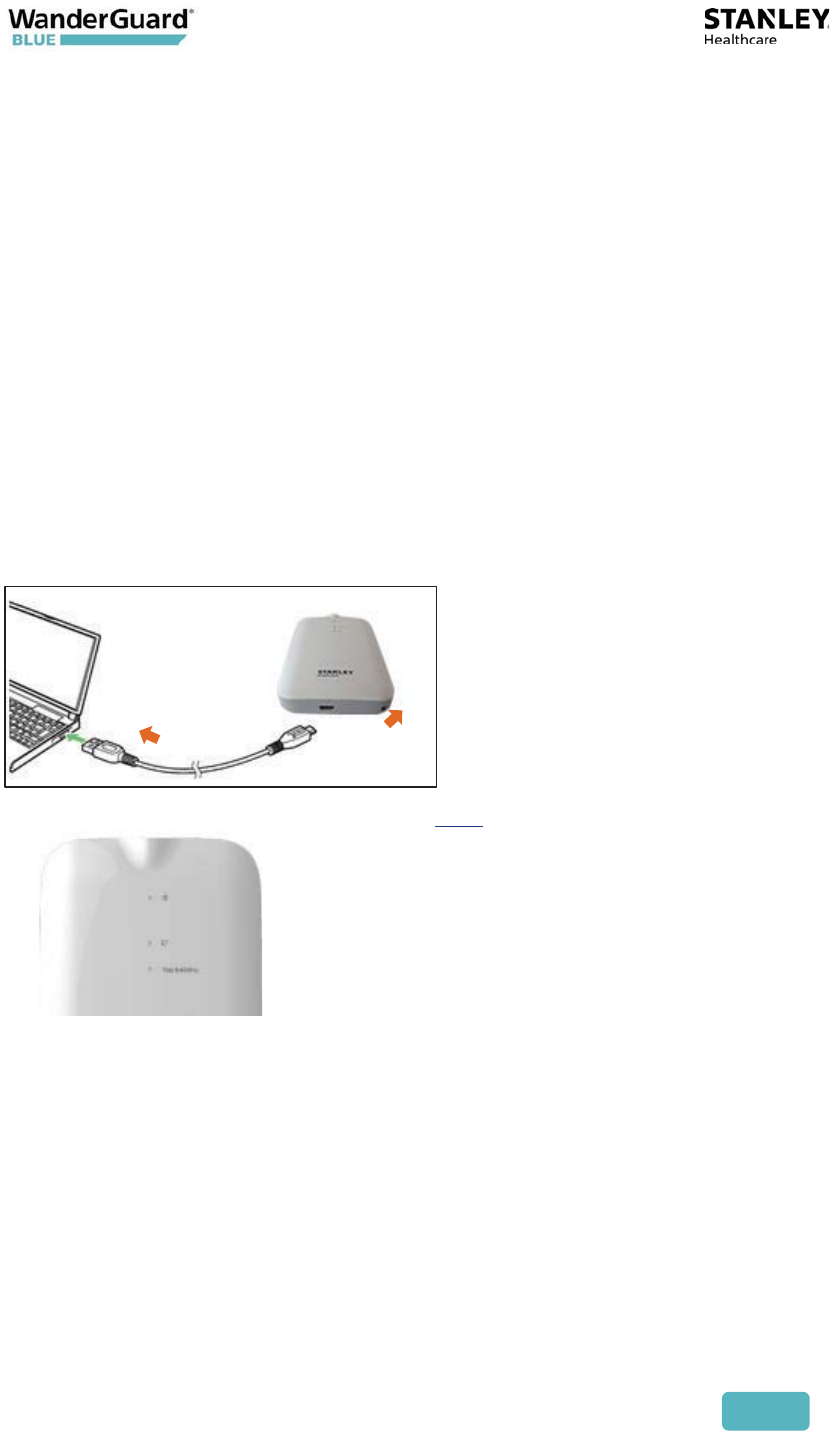
Connecting the Detector to a PC
1. Turn ON the PC or laptop.
2. Turn ON the WanderGuard BLUE Detector by short-clicking the power button.
3. Connect the Detector to your computer using the supplied micro-USB cable
by inserting the USB end of the cable into an available USB port.
4. Insert the micro-USB connector into the port located in the bottom-end of
the Detector.
5. The Detector power LED turns on. See LEDs.
6. Device drivers are automatically installed the first time the Detector is
connected to a PC.
Using the TED Device Manager
The TED Device Manager component of the STANLEY Healthcare's Hardware
Manager application is used to:
x Connect to the Detector to view the Detector’s battery status
x Upgrade the Detector firmware