Andrew Wireless Innovations Group RPT-MR701 REPEATER User Manual M0067A0A
Andrew Wireless Innovations Group REPEATER M0067A0A
UserManual.wiki
>
Andrew Wireless Innovations Group
>
RPT-MR701 User Manual
>
REPEATER MANUAL
Contents
1.
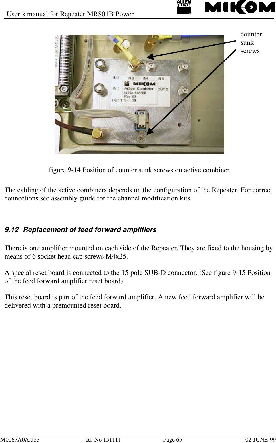
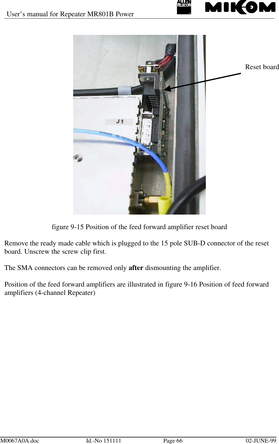
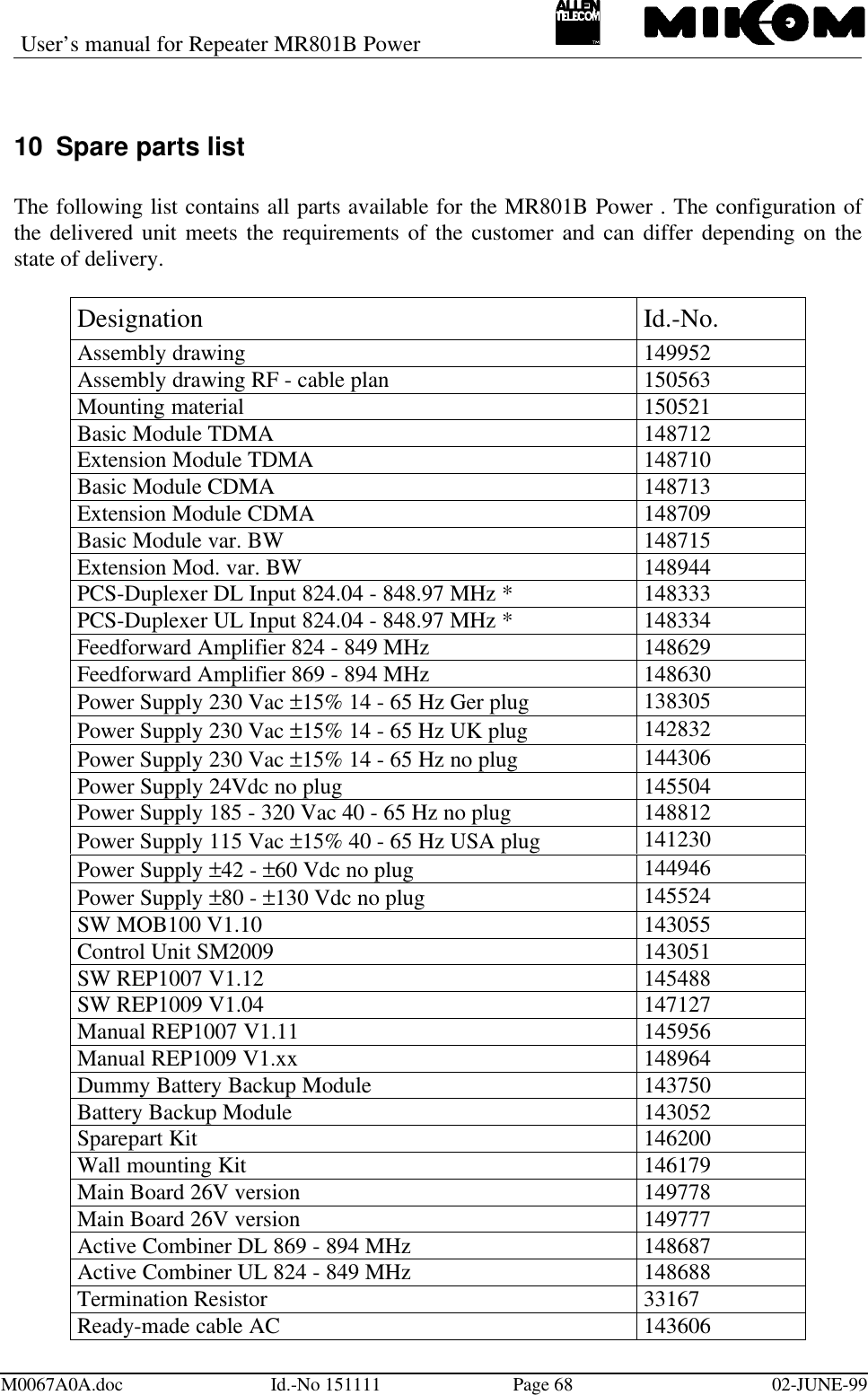
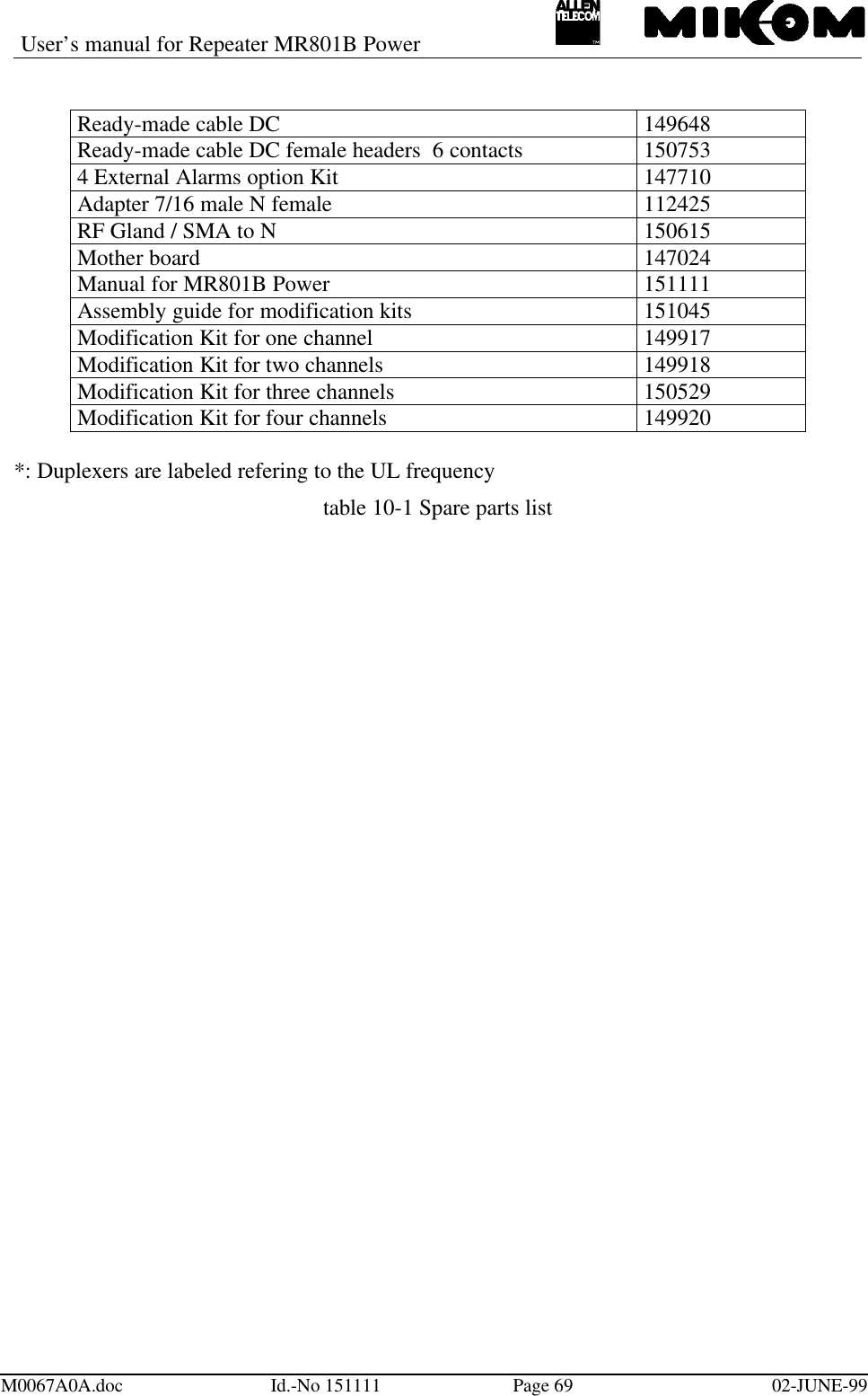
REPEATER MANUAL
2.
Software manual
3.
Functional description and integration instructions manual
4.
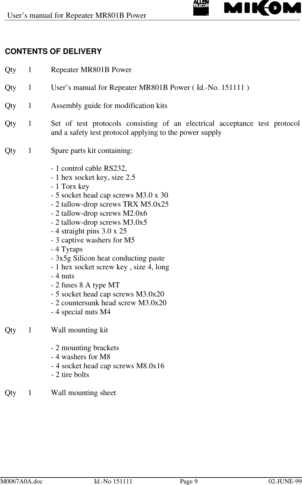
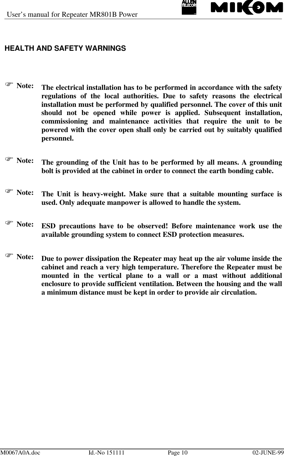
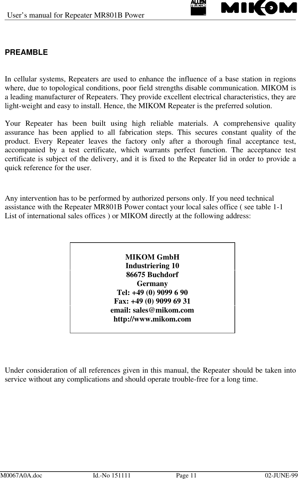
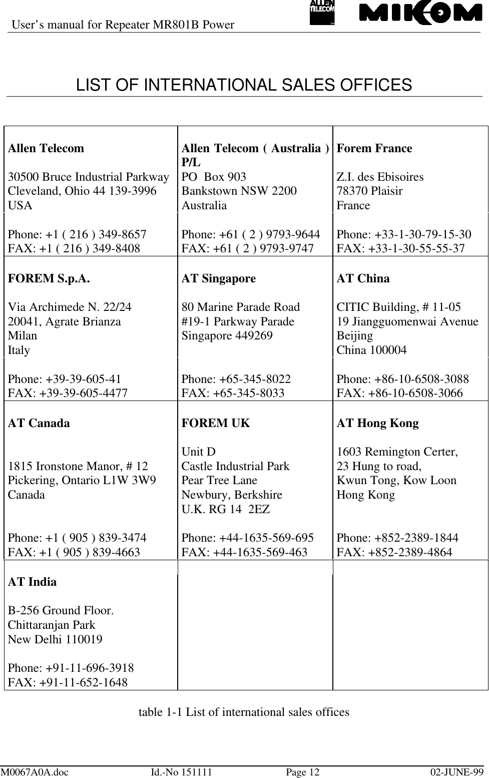
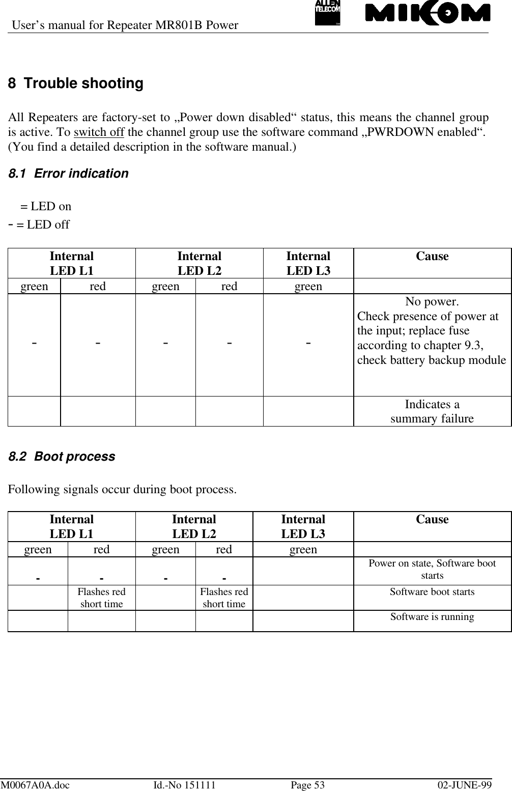
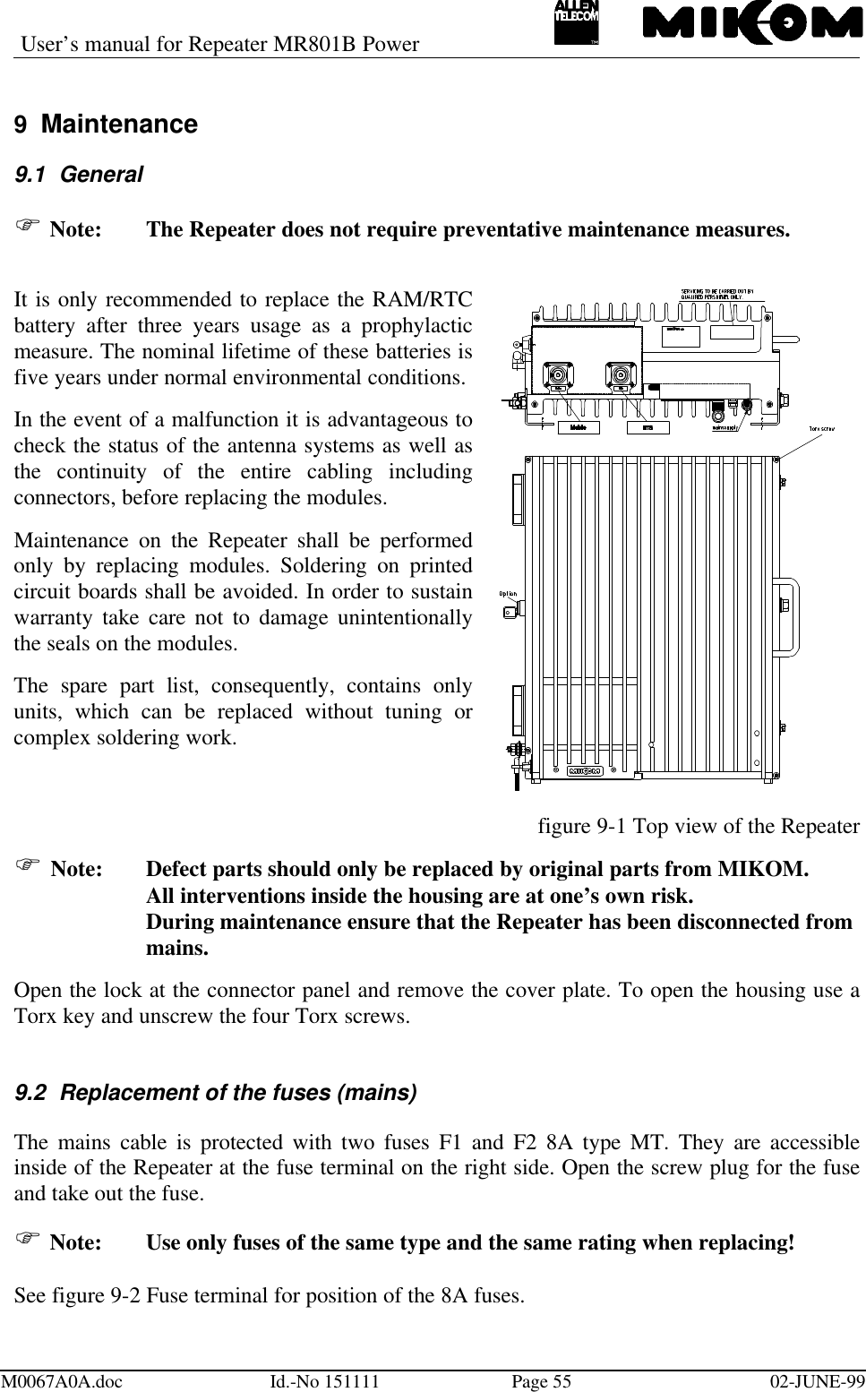
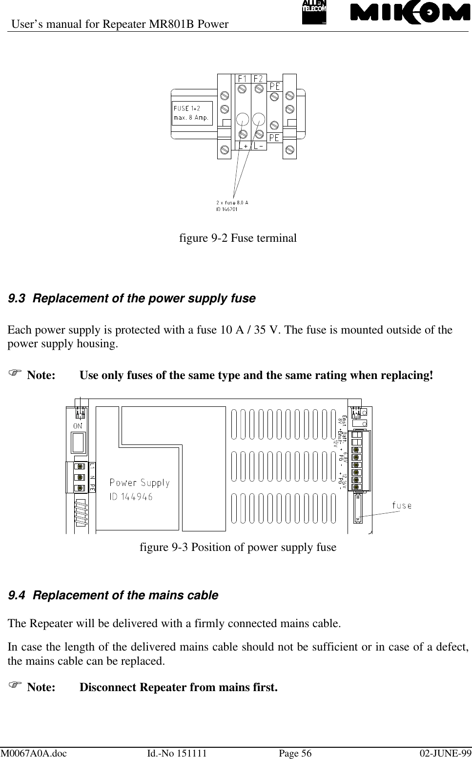
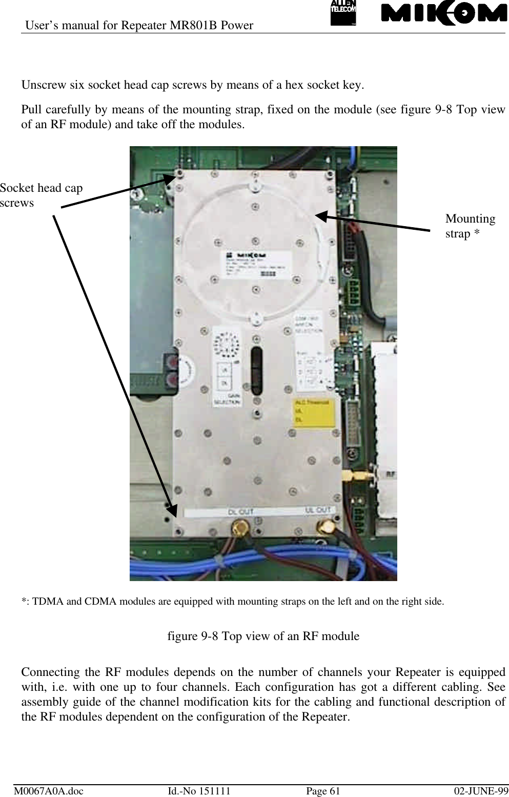
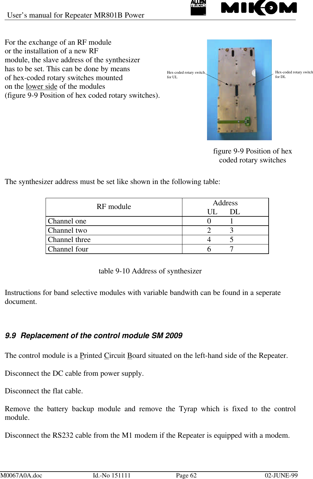
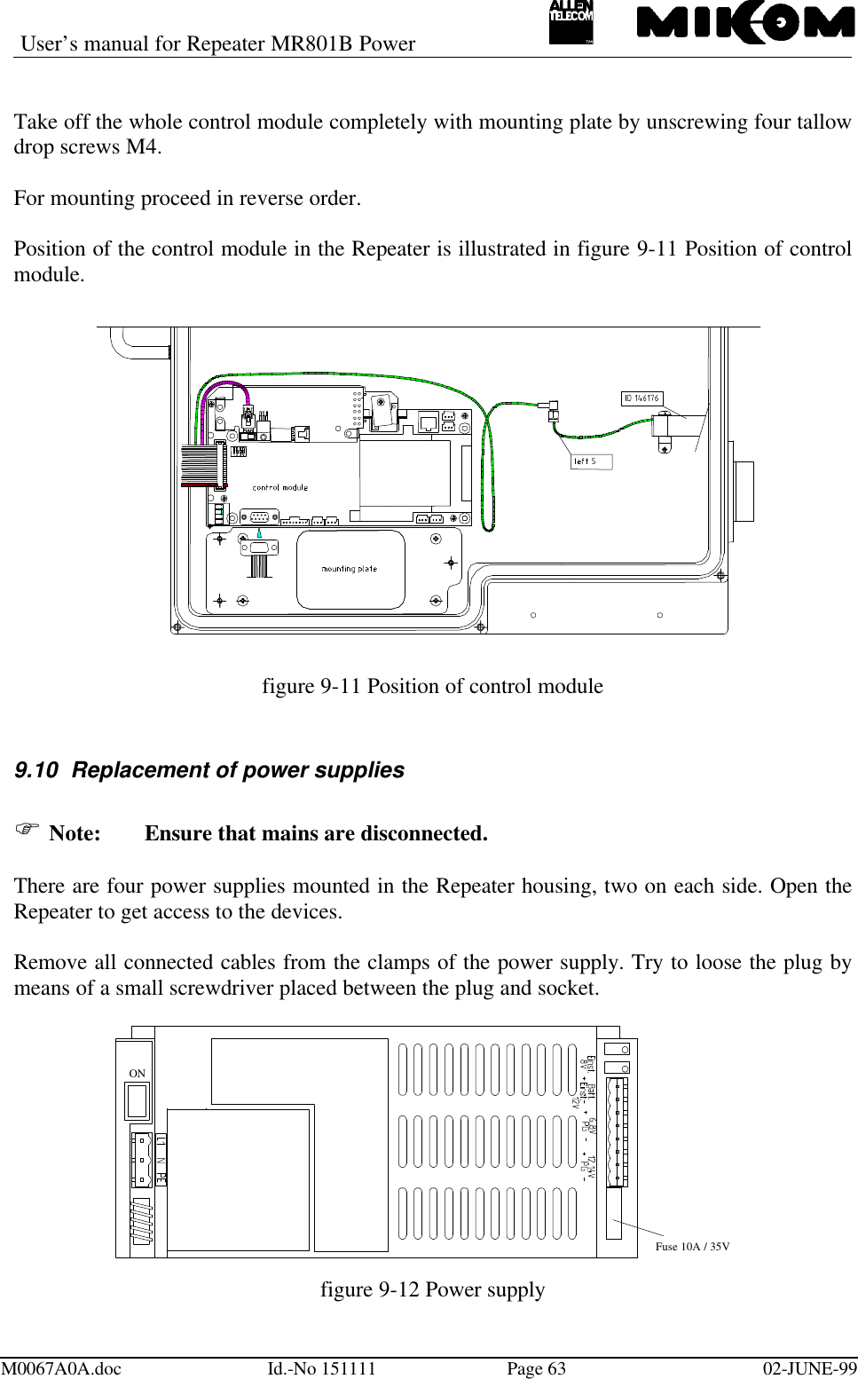
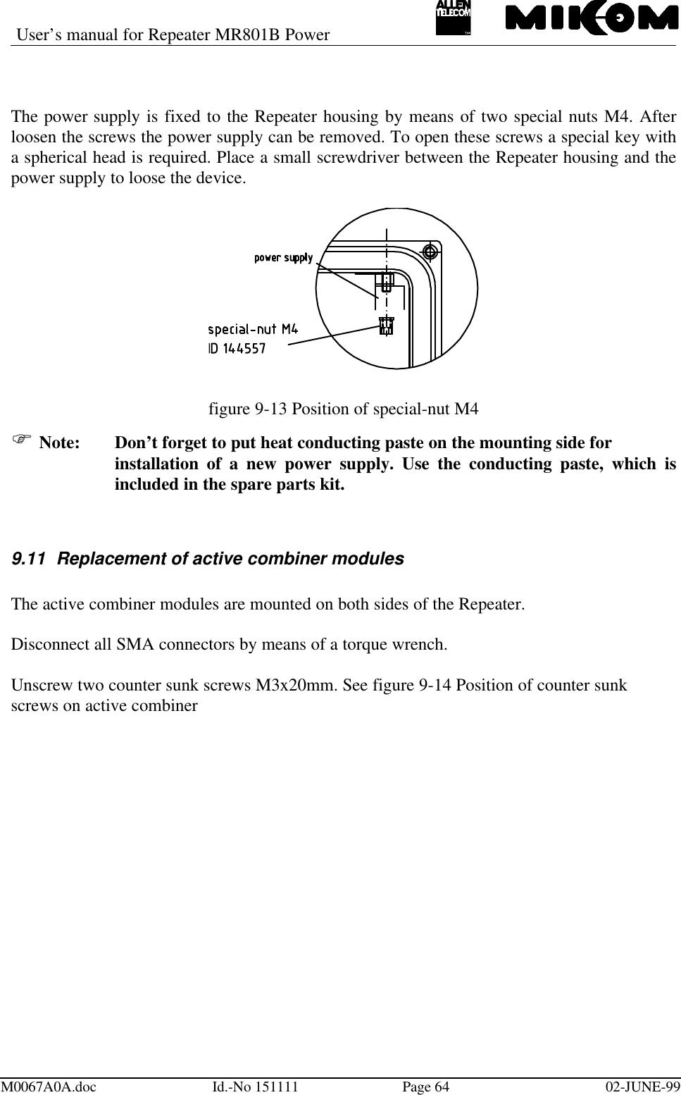
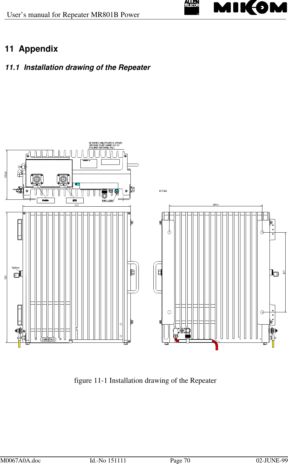
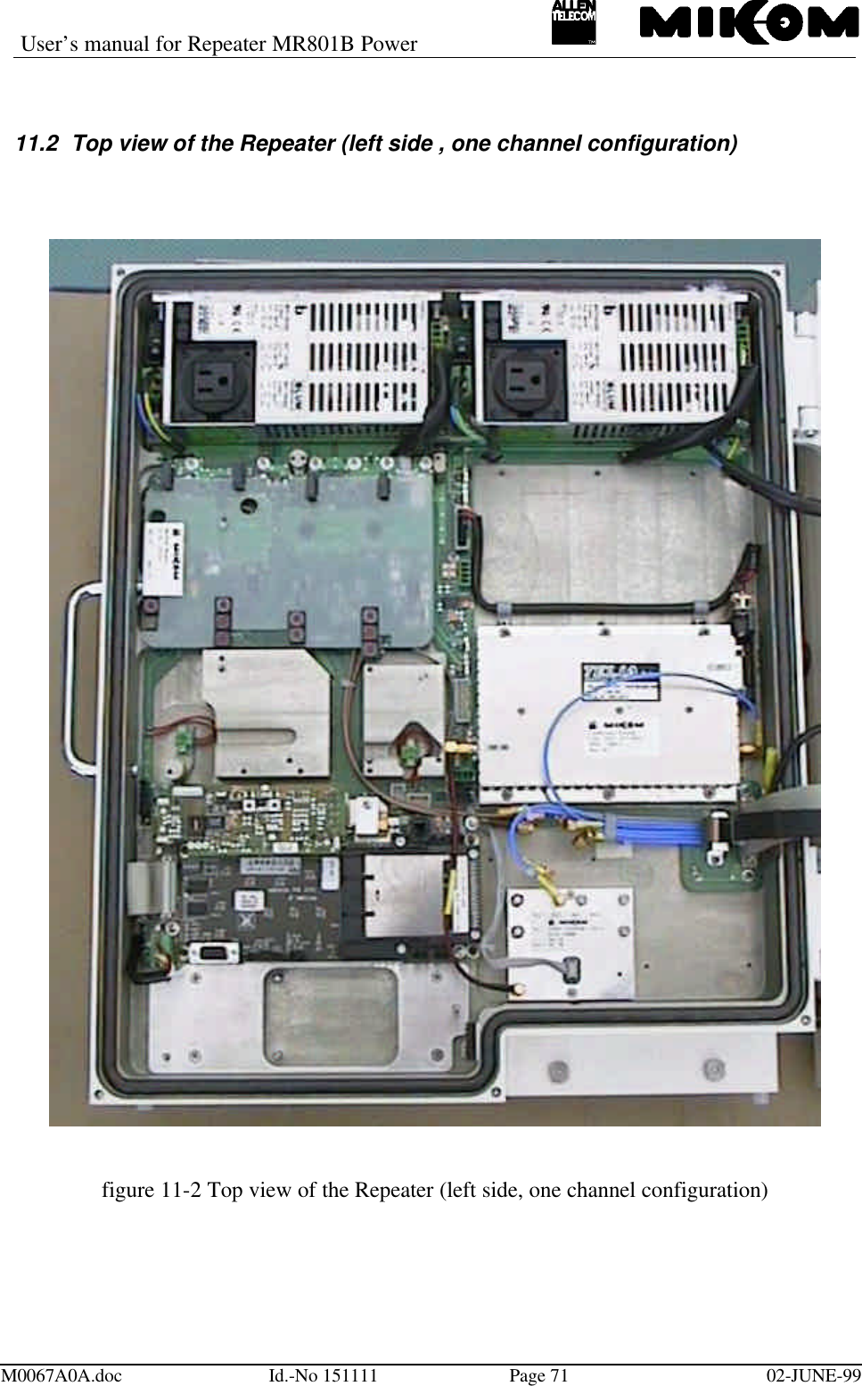
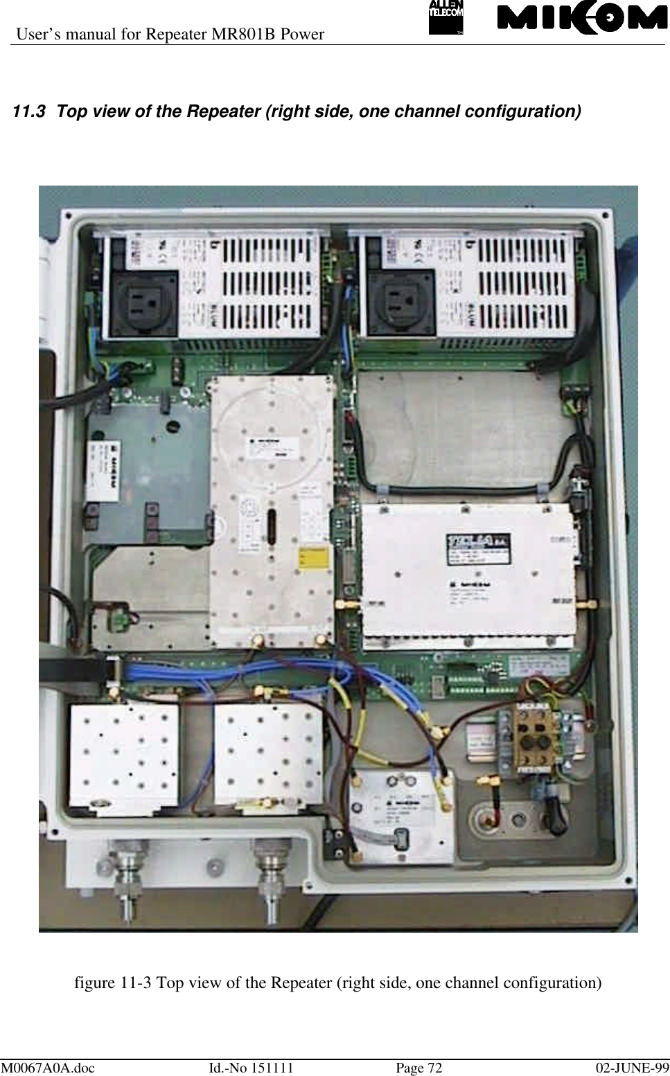
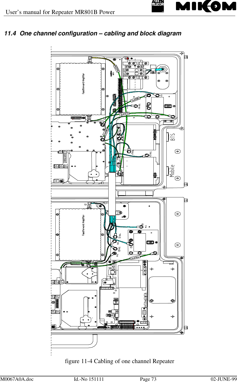
Repeater manual
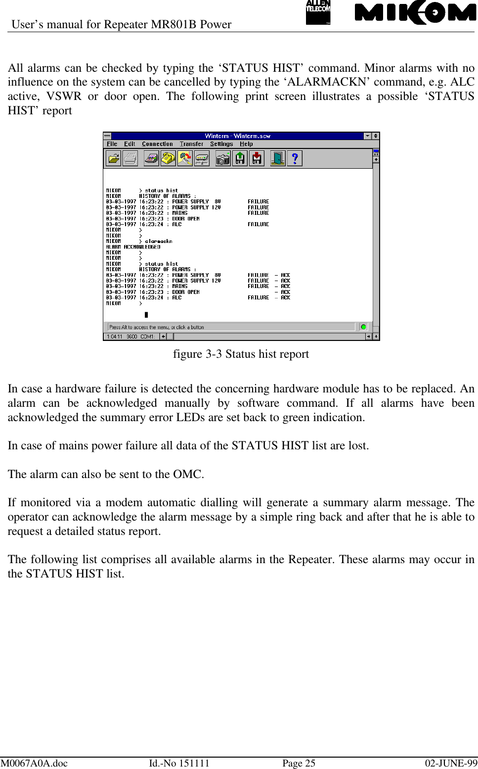
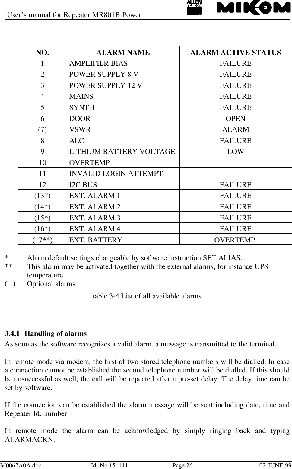
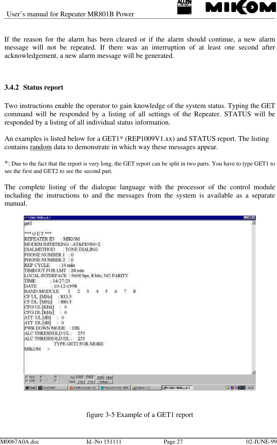
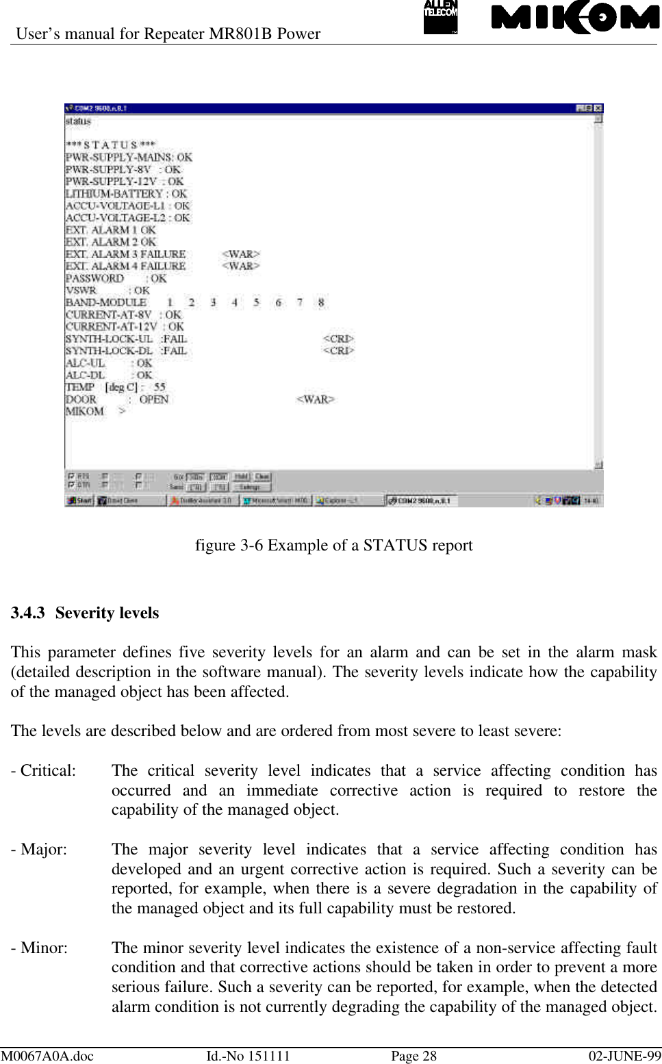
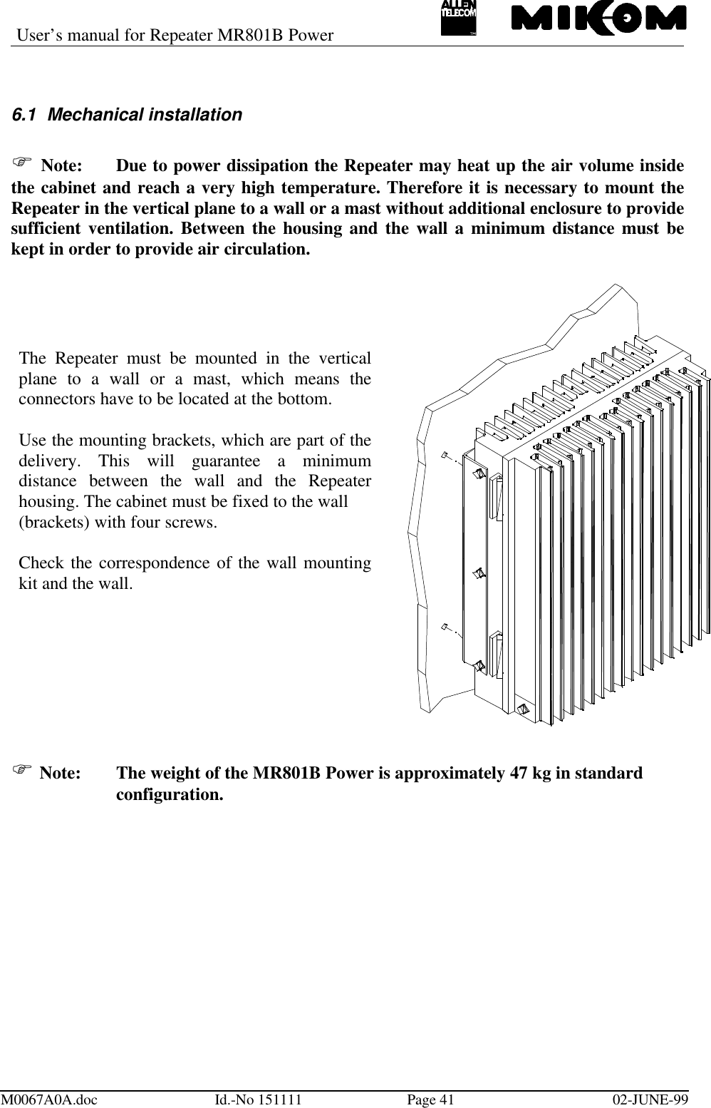
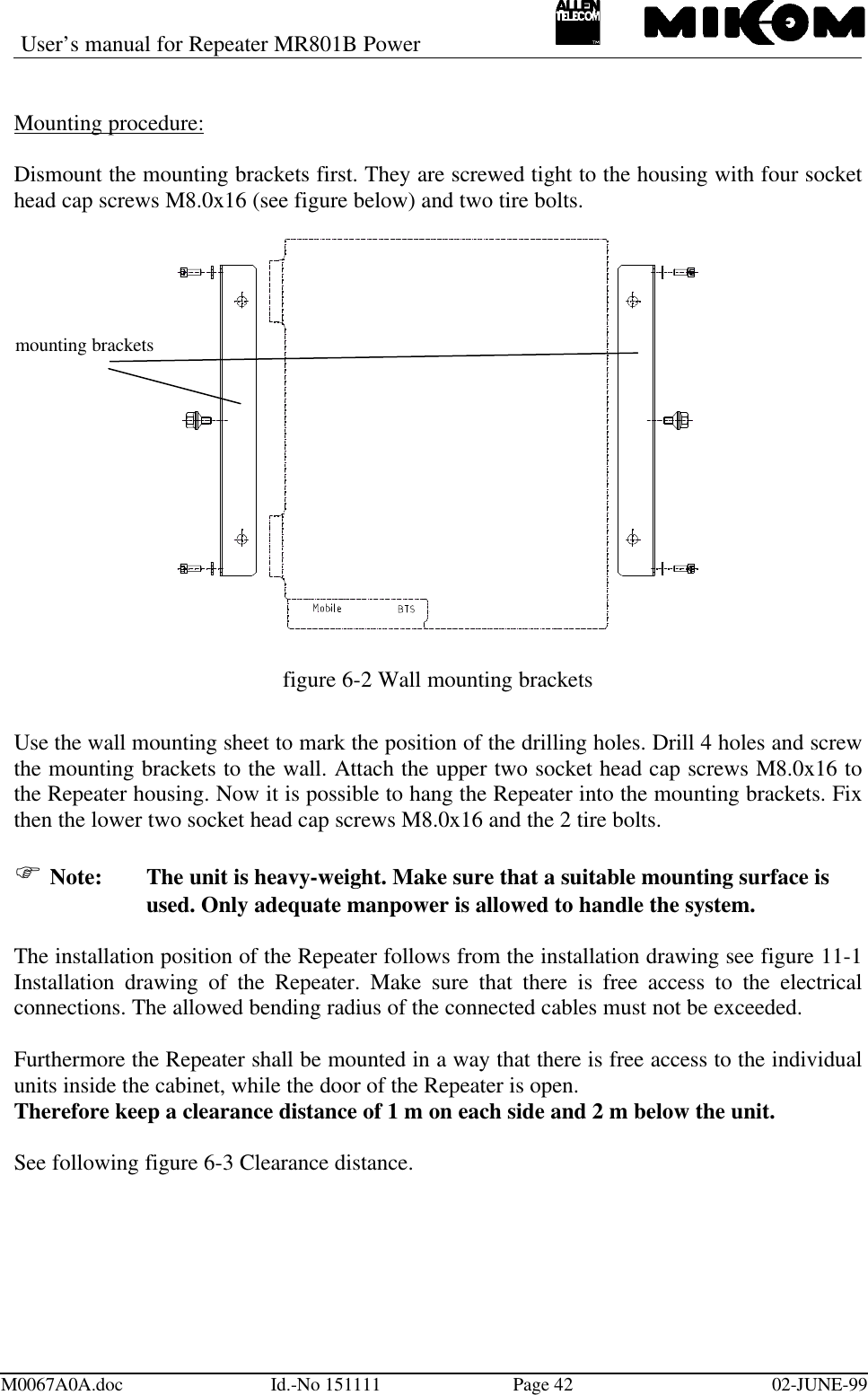
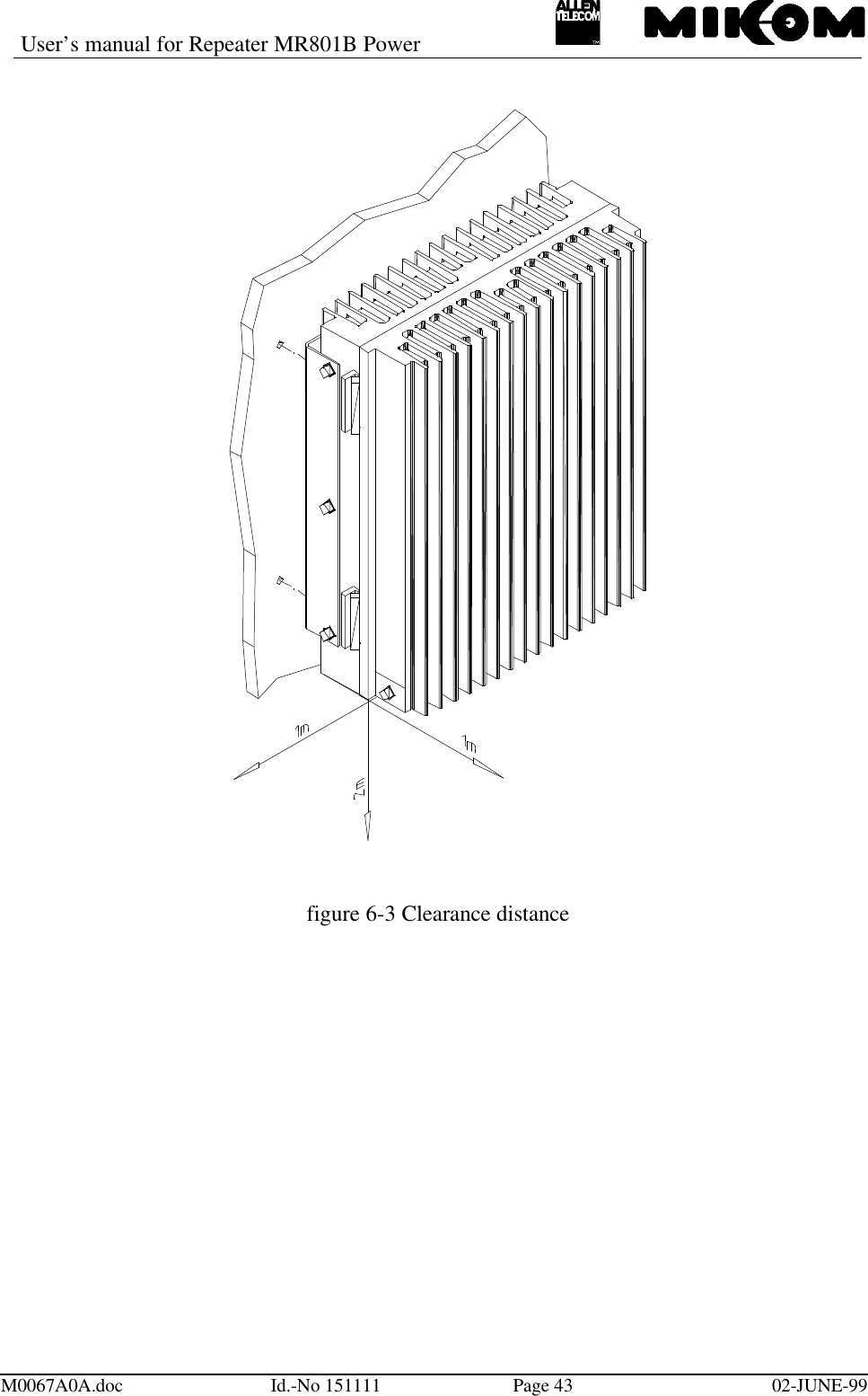
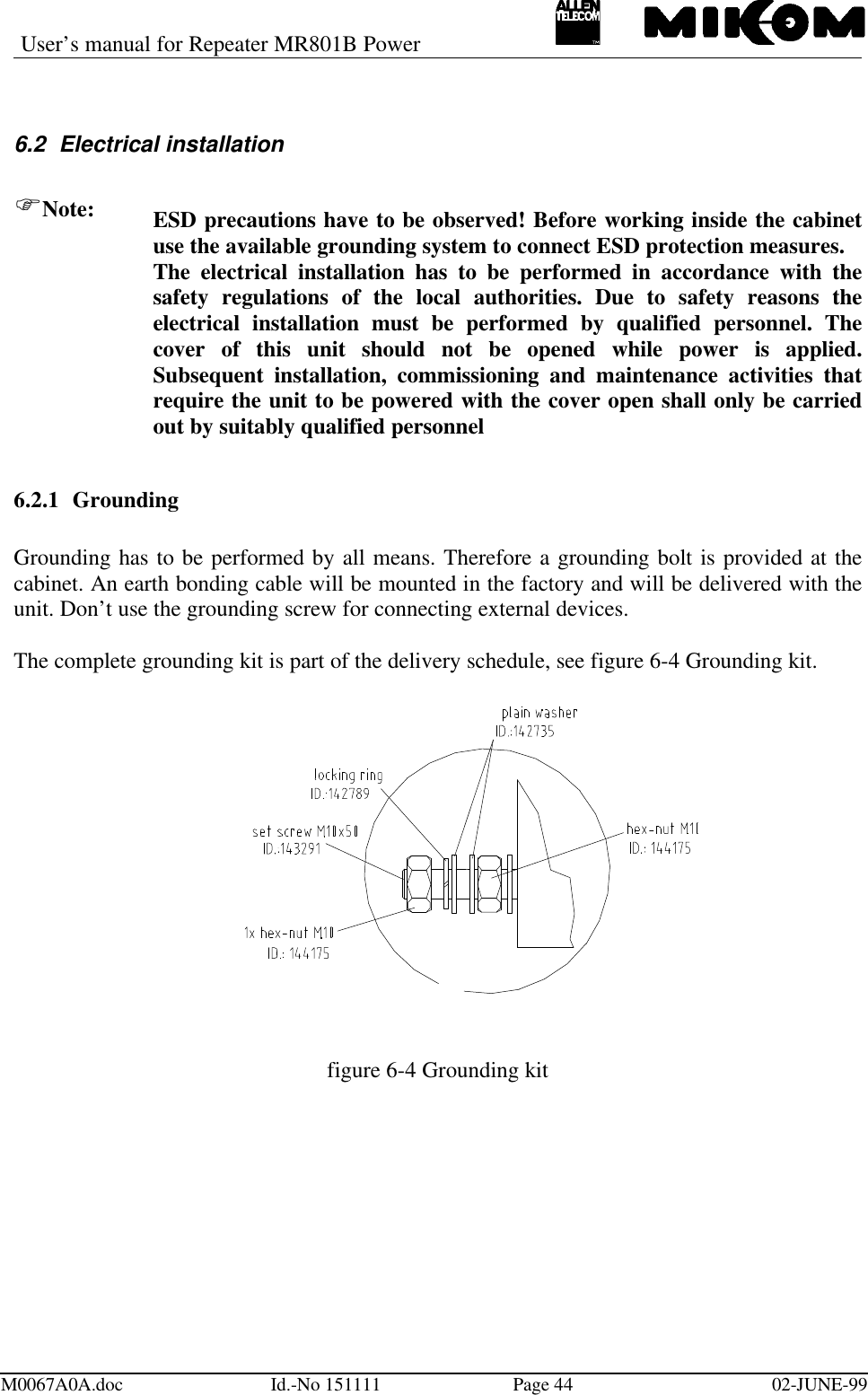
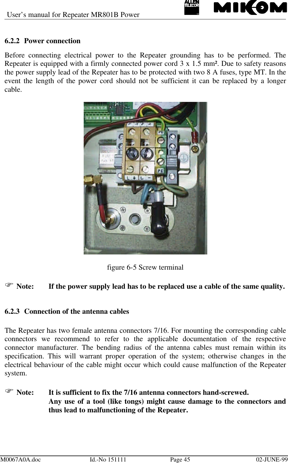
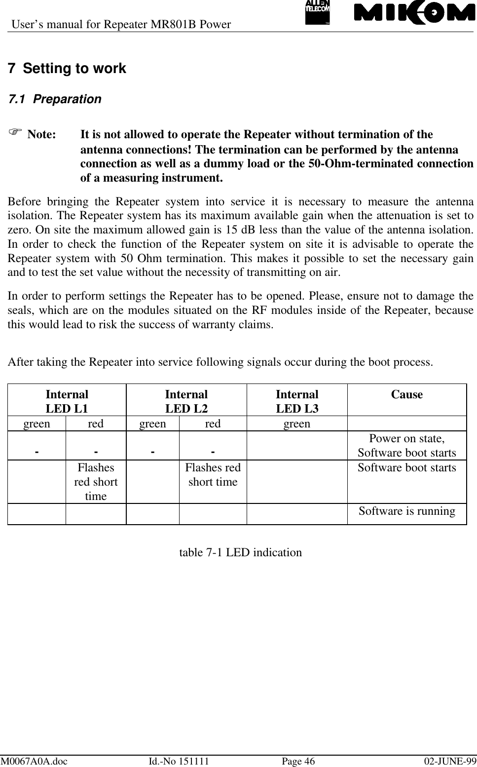
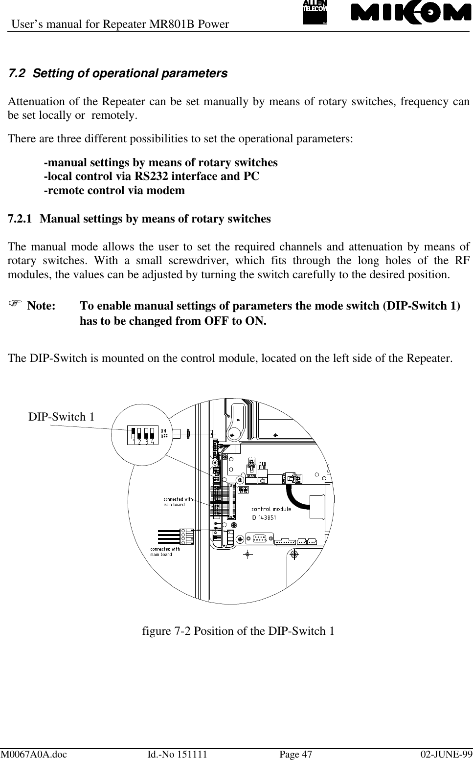
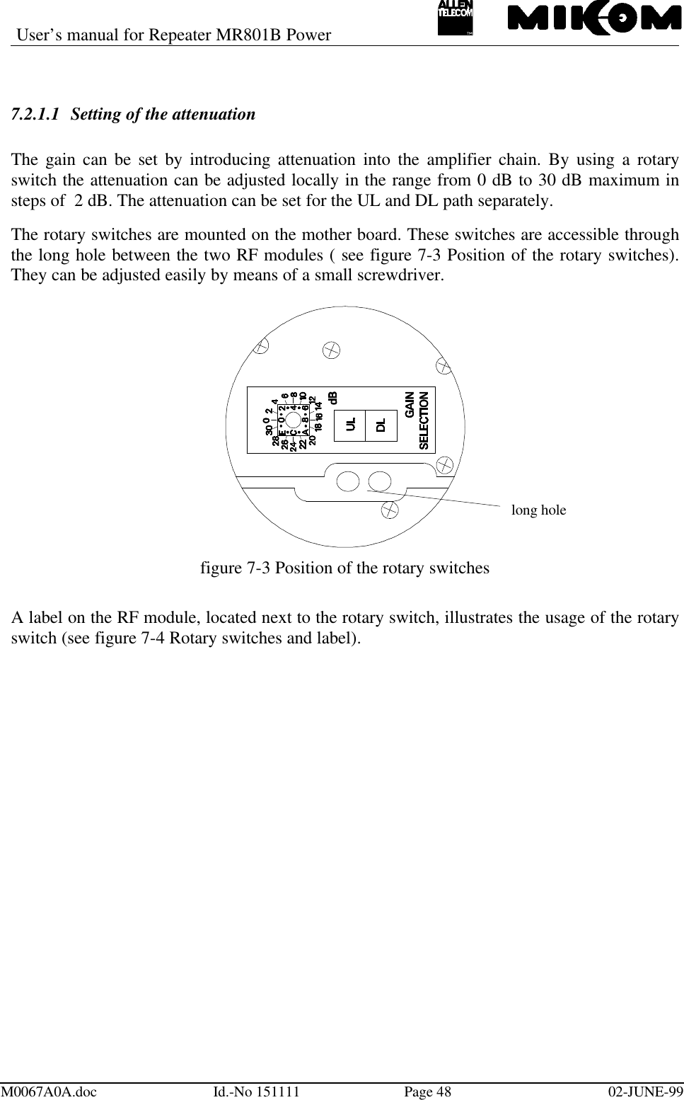
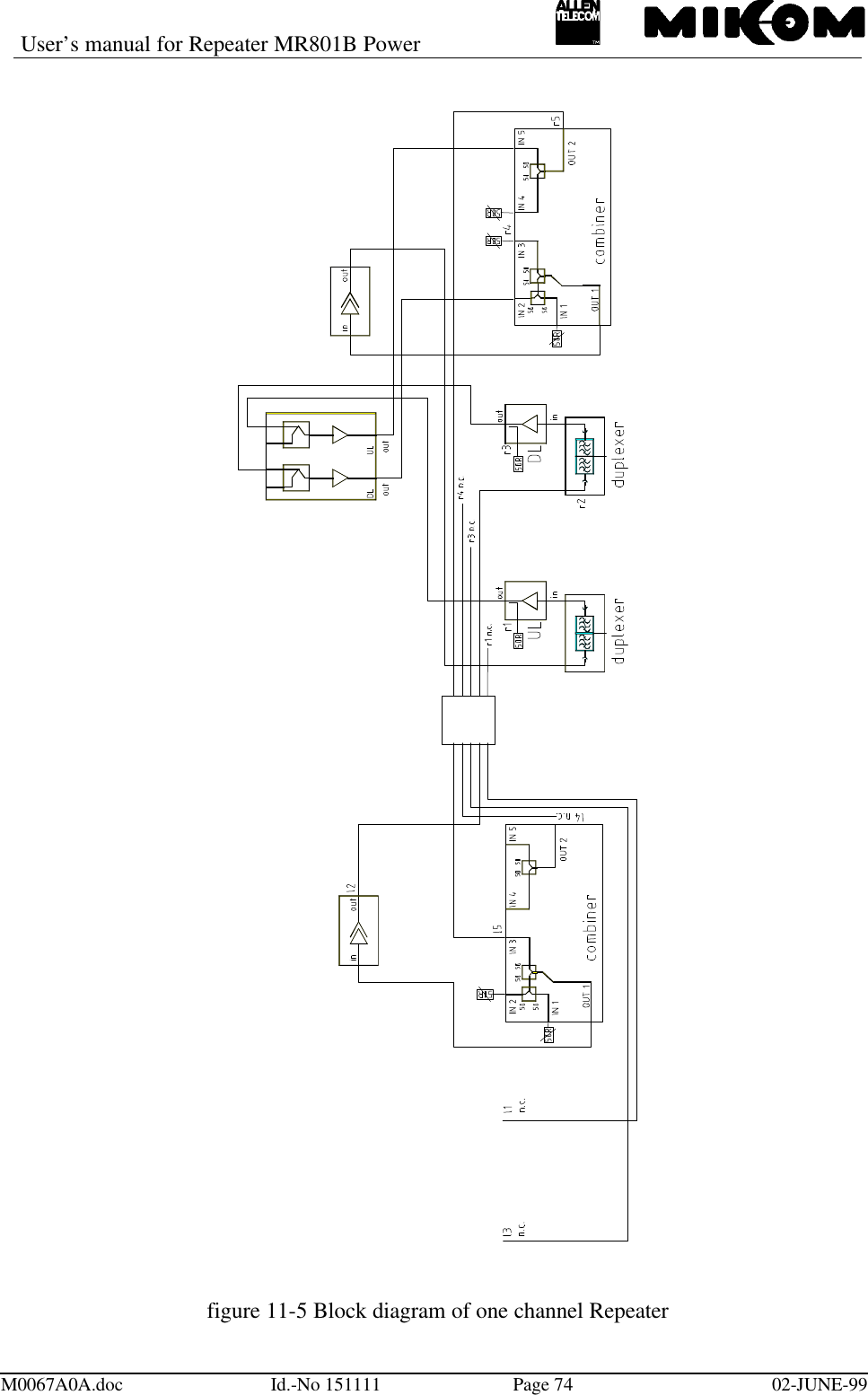
REPEATER MANUAL
Navigation menu
Upload a User Manual
Namespaces
Wiki Guide
HTML
PDF
Info
Views
User Manual
Discussion / Help
Navigation