Becker Avionics TG660 Aircraft radio User Manual Transceiver Family 620X
Becker Avionics, Inc. Aircraft radio Transceiver Family 620X
UserManual.wiki
>
Becker Avionics
>
TG660 User Manual
>
Manual_Family
Contents
1.
Manual_Family
2.
Manual_PA3-2AB-AIR
3.
Manual_TG660
4.
User Manual
5.
Datasheet
Manual_Family
Navigation menu
Upload a User Manual
Namespaces
Wiki Guide
HTML
PDF
Info
Views
User Manual
Discussion / Help
Navigation
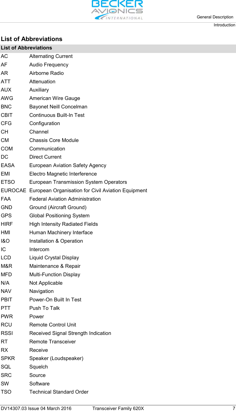

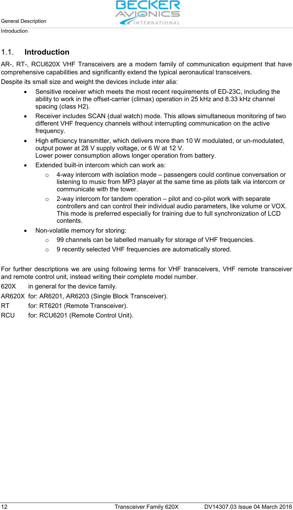
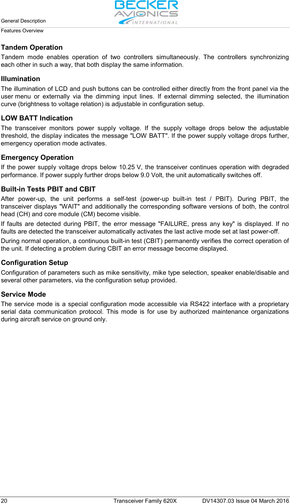
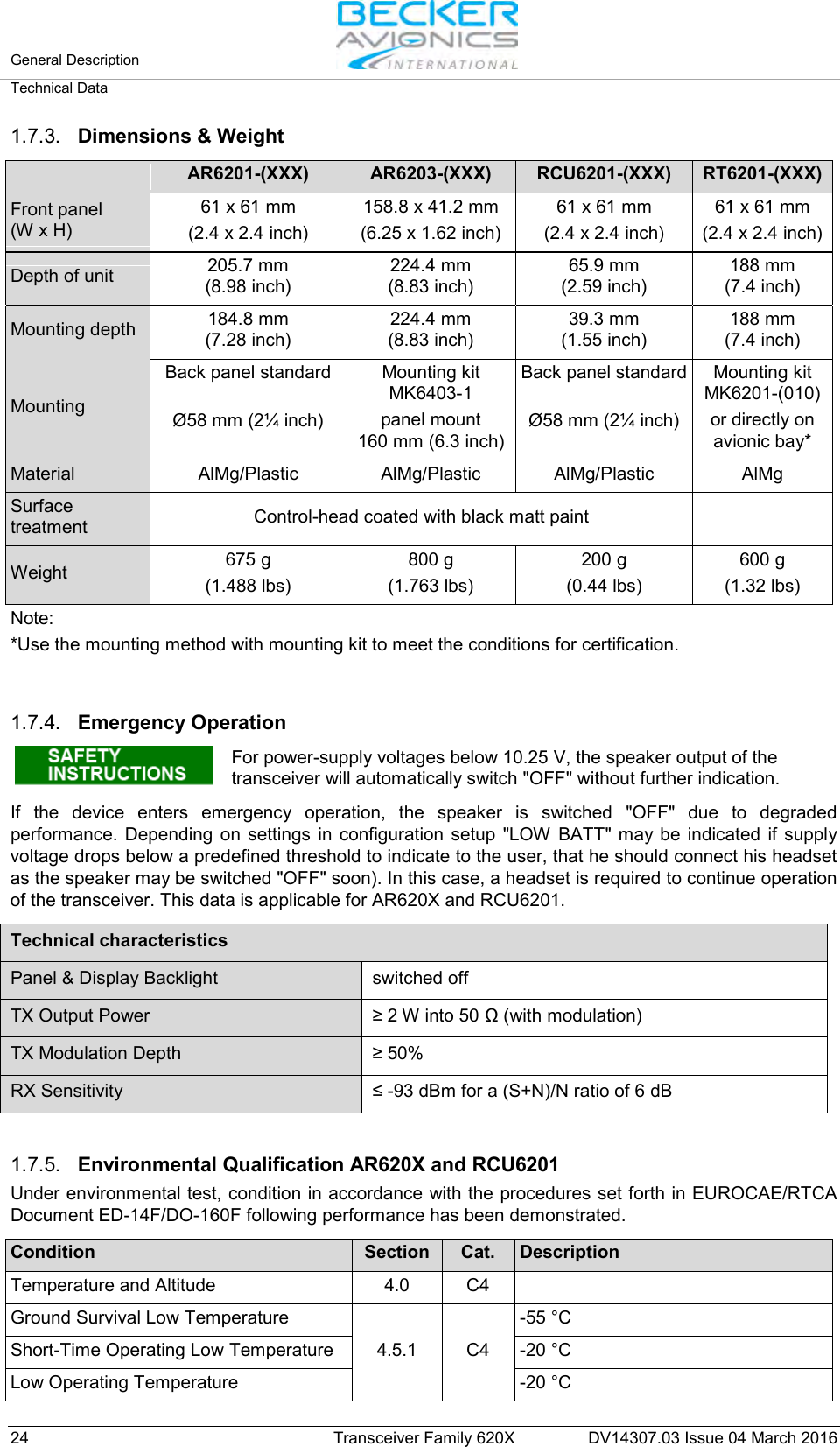
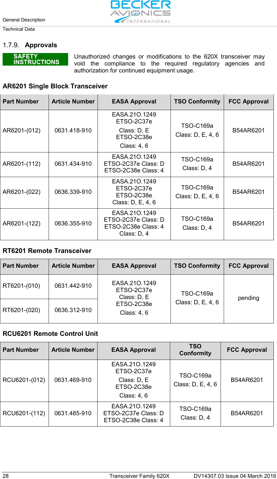
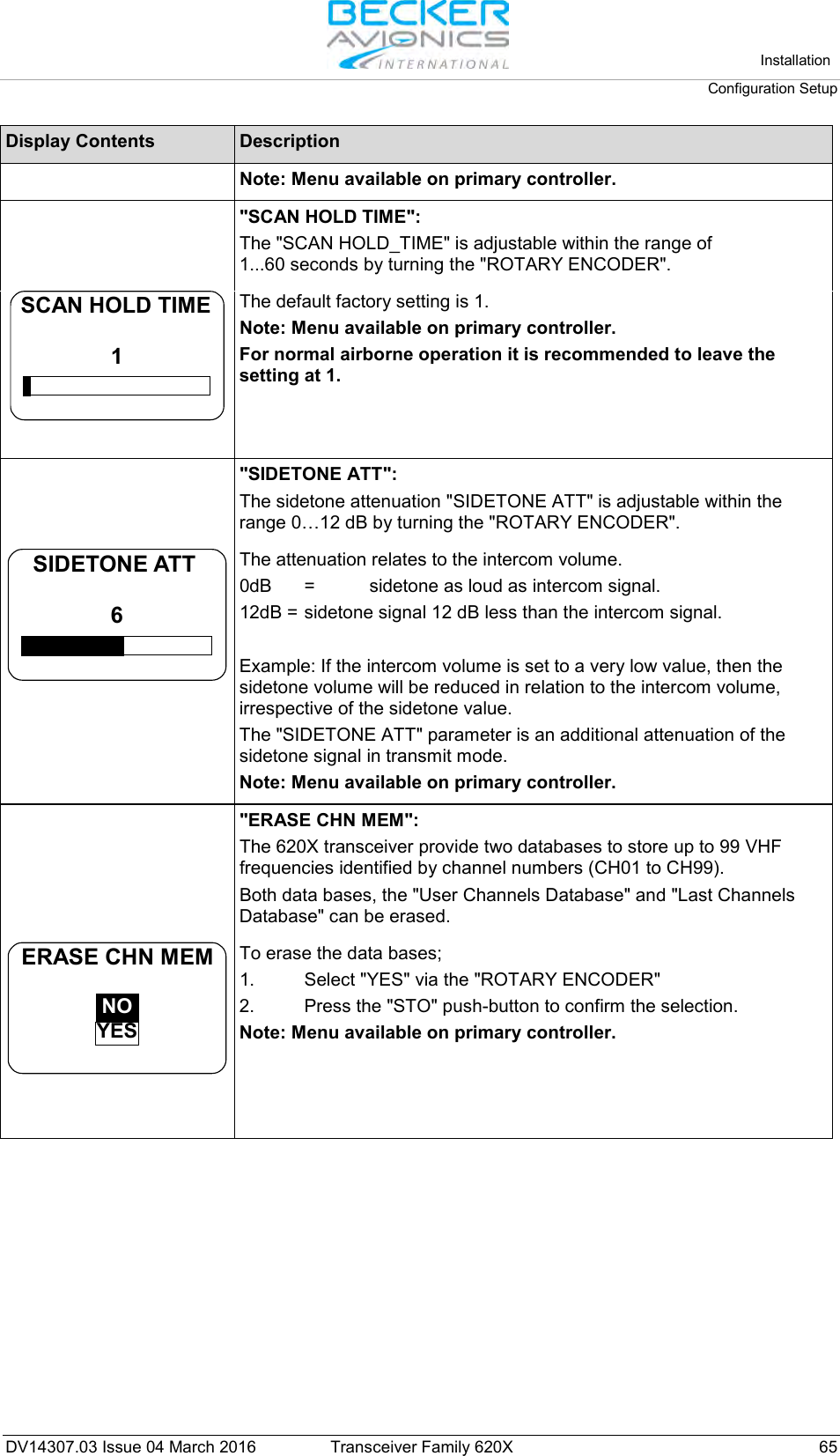
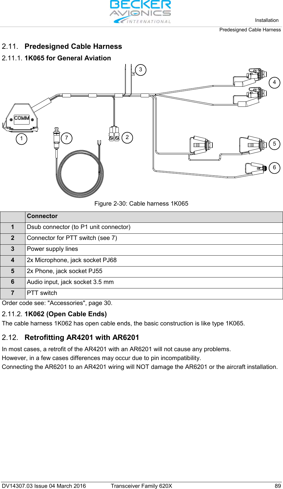
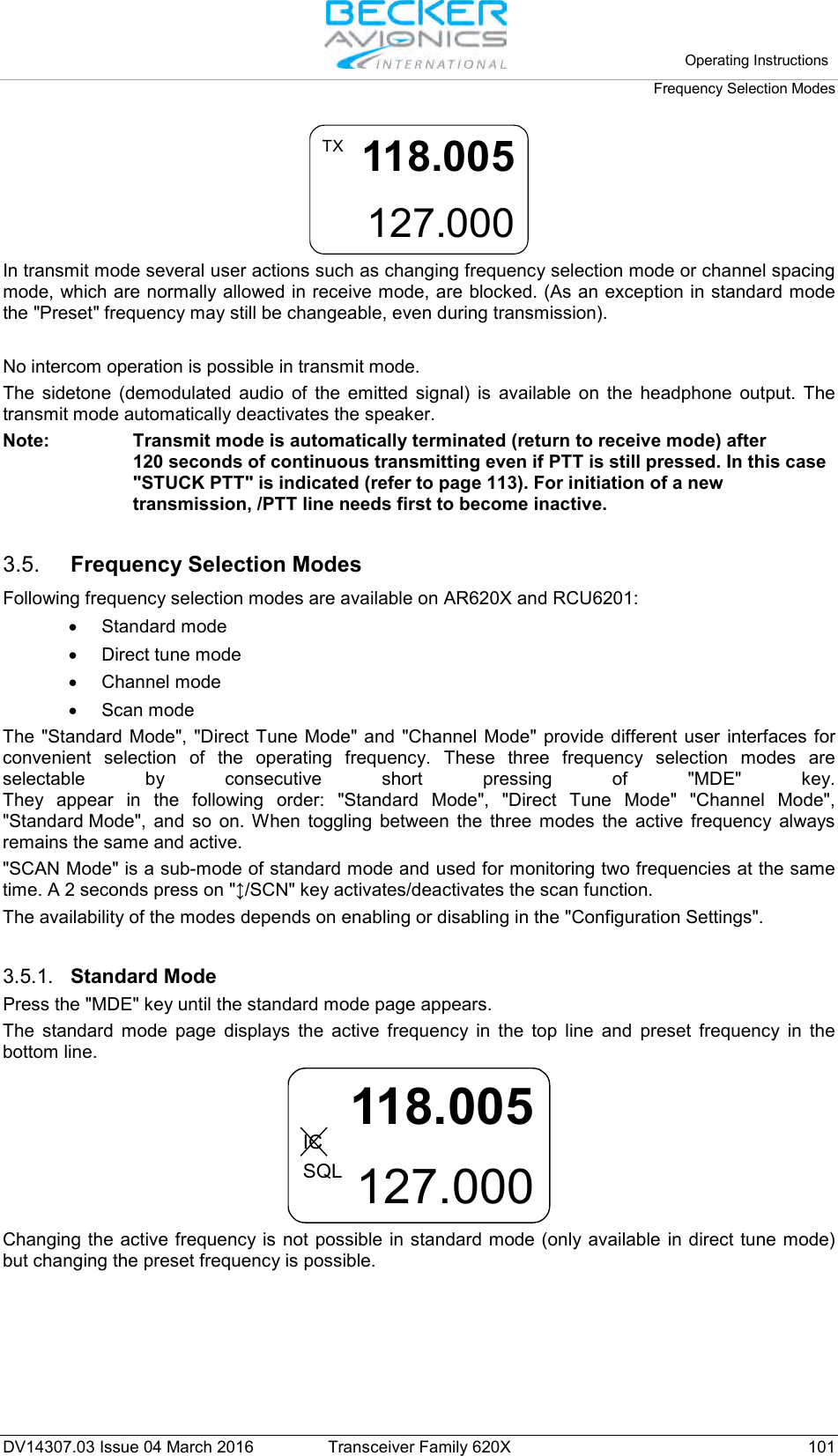
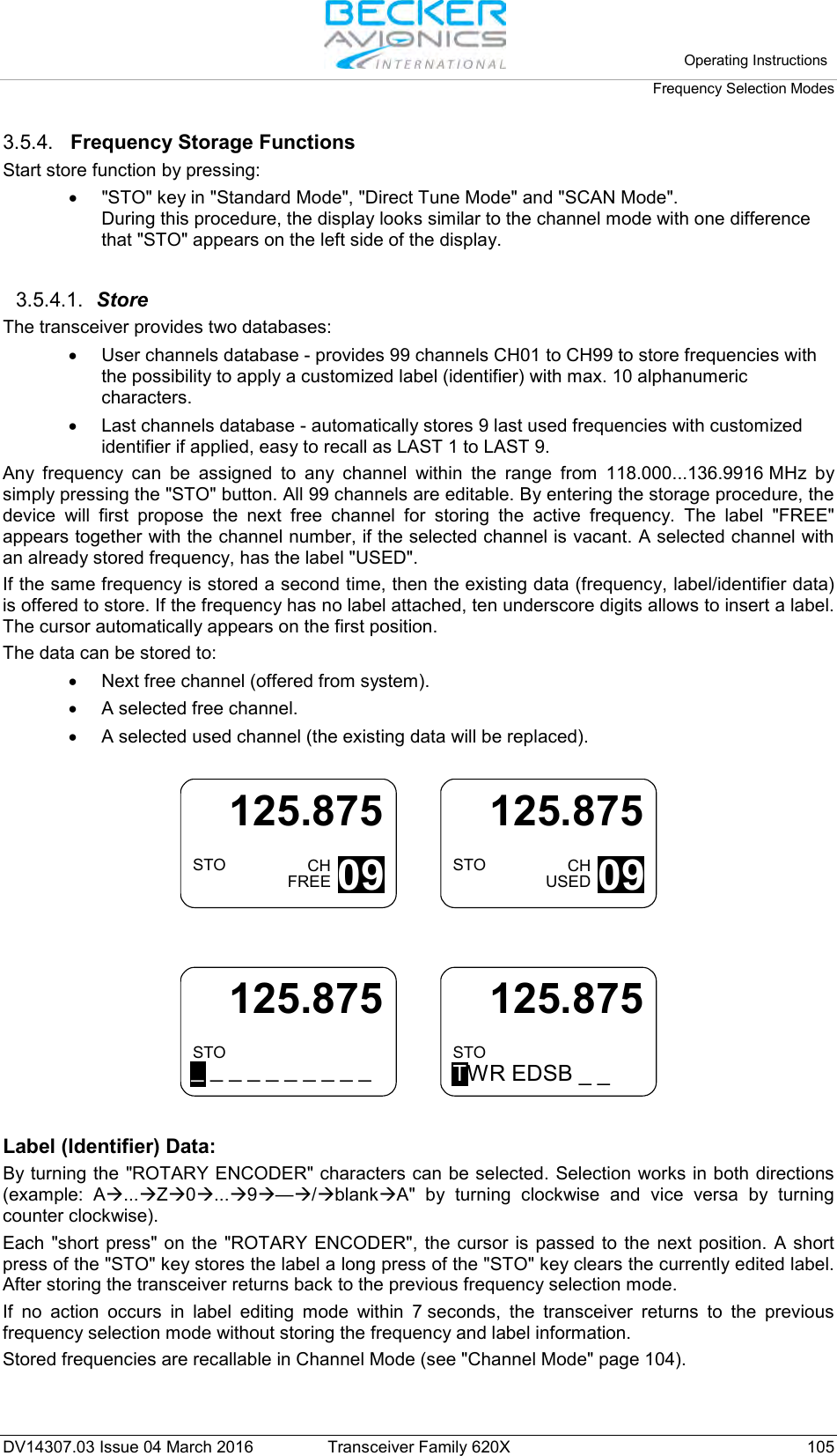
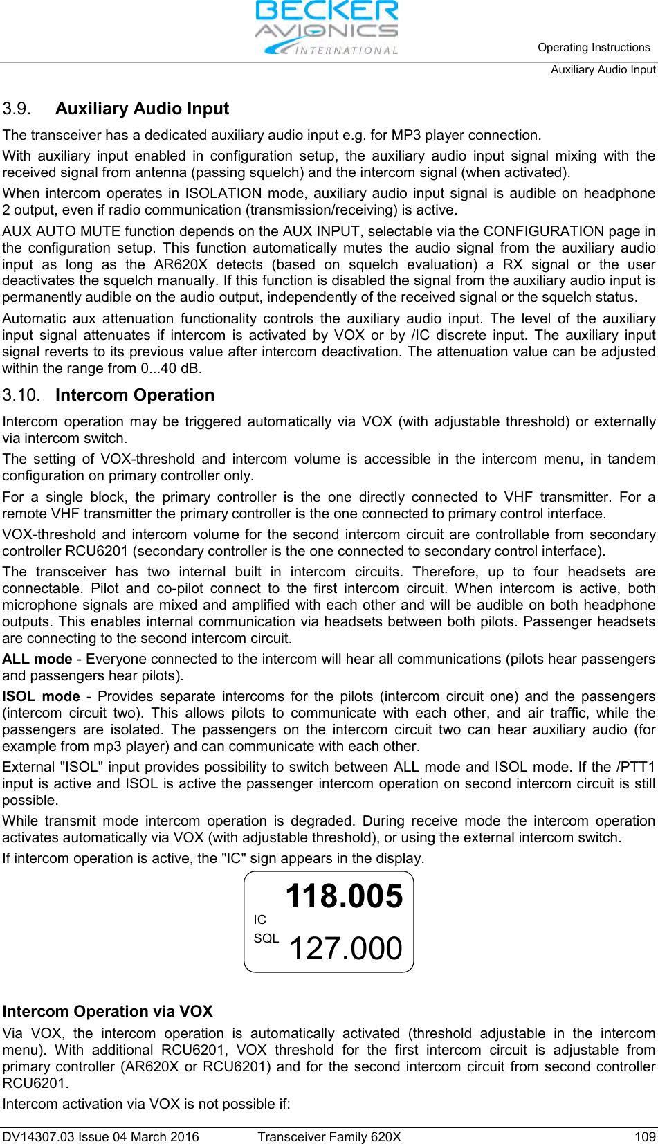
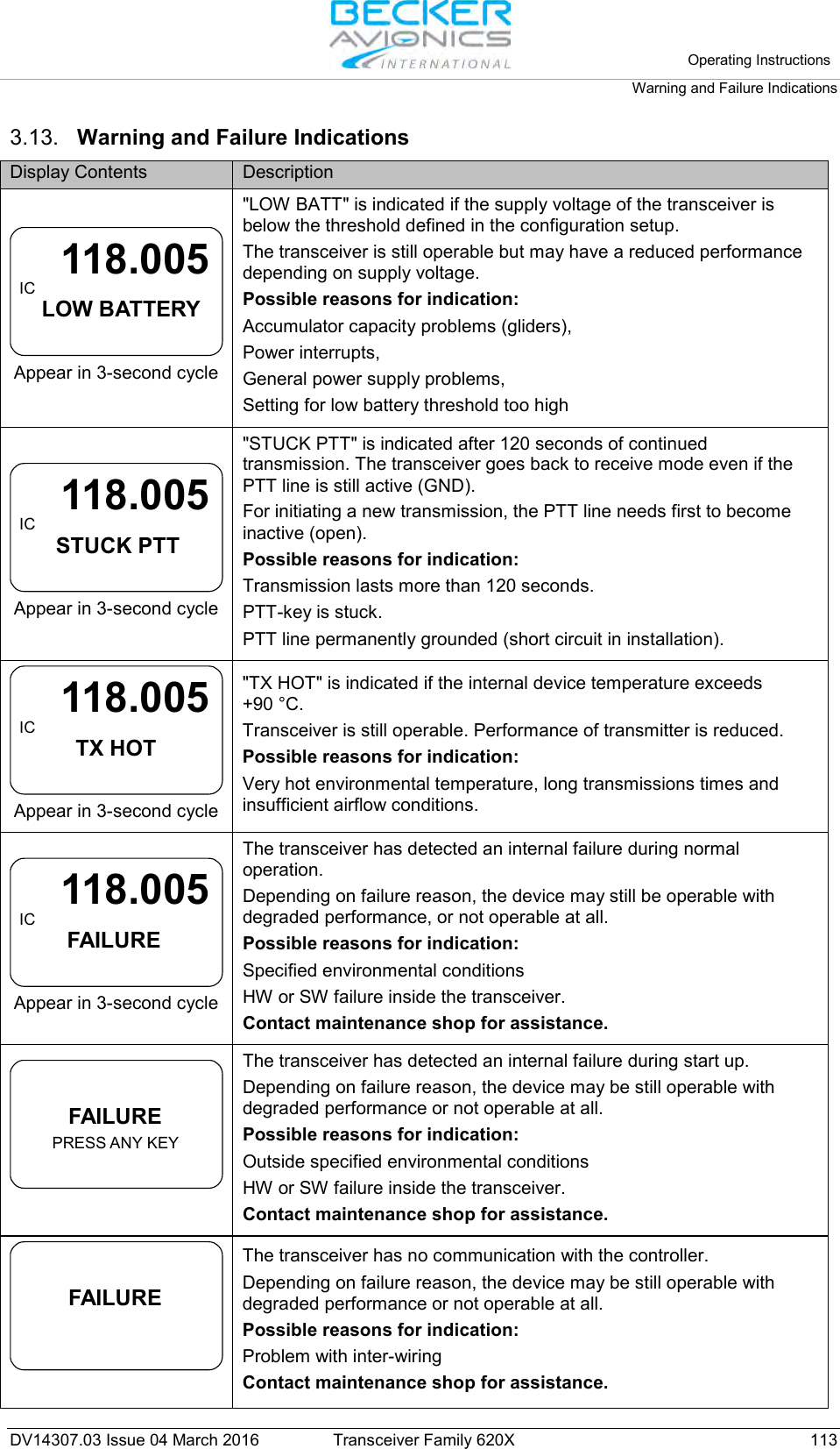
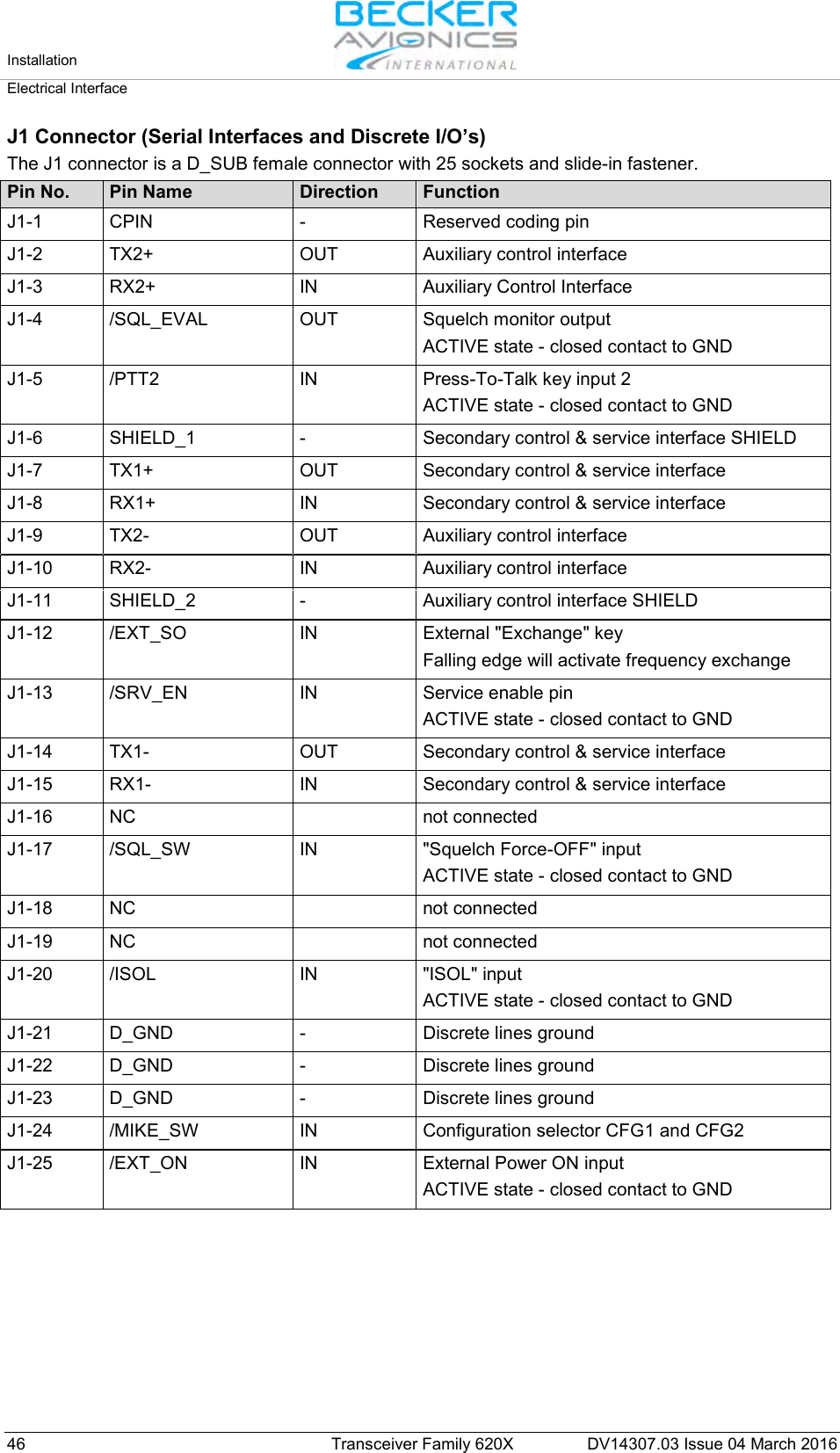
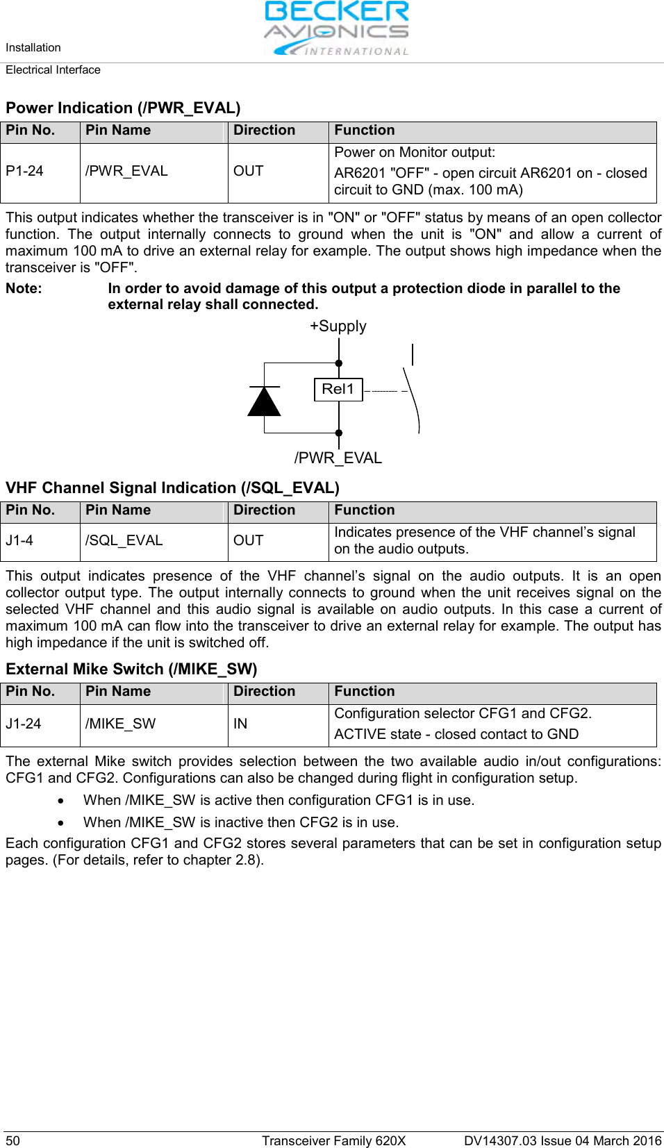
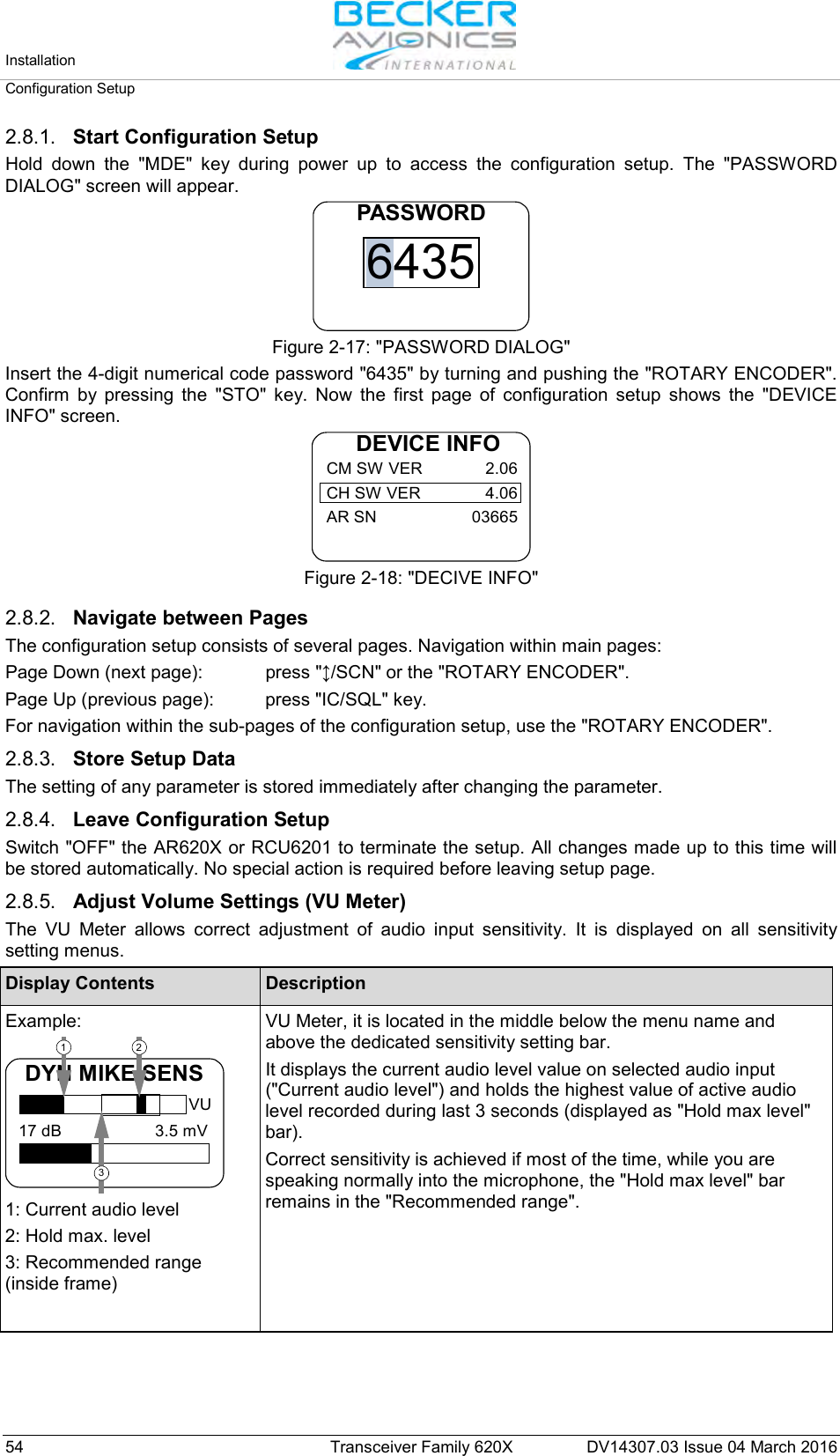
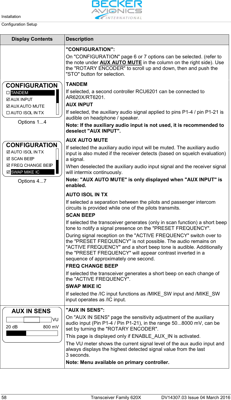
![General Description Technical Data DV14307.03 Issue 04 March 2016 Transceiver Family 620X 29 AR6203 Single Block Transceiver Part Number Article Number EASA Approval TSO Conformity FCC Approval AR6203-(012) 0630.993-910 EASA.21O.10054849 ETSO-2C169a Class: C, H2, 4, 6 TSO-C169a Class: D, E, 4, 6 pending AR6203-(112) 0631.566-910 EASA.21O.10054849 ETSO-2C169a Class: C, 4 TSO-C169a Class: C, 4 pending AR6203-(022) 0636.371-910 EASA.21O.10054849 ETSO-2C169a Class: C, H2, 4, 6 TSO-C169a Class: D, E, 4, 6 pending AR6203-(122) 0636.398-910 EASA.21O.10054849 ETSO-2C169a Class: C, 4 TSO-C169a Class: C, 4 pending 1.7.9.1. FCC Approval Radiofrequency radiation exposure information: This equipment complies with FCC radiation exposure limits set forth for an uncontrolled environment. This equipment should be installed and operated with minimum distance of 50 cm between the radiator and your body. This transmitter must not be co-located or operating in conjunction with any other antenna or transmitter. NOTE: This equipment has been tested and found to comply with the limits for a Class A digital device, pursuant to Part 15 of the FCC Rules. These limits are designed to provide reasonable protection against harmful interference when the equipment is operated in a commercial environment. This equipment generates, uses, and can radiate radio frequency energy and, if not installed and used in accordance with the instruction manual, may cause harmful interference to radio communications. Operation of this equipment in a residential area is likely to cause harmful interference in which case the user will be required to correct the interference at his own expense. NOTE: This device complies with Part 15 of the FCC Rules [and with Industry Canada licence-exempt RSS standard(s)]. Operation is subject to the following two conditions: • This device may not cause harmful interference, and • This device must accept any interference received, including interference that may cause undesired operation. NOTE: Changes or modifications made to this equipment not expressly approved by Becker Avionics may void the FCC authorization to operate this equipment.](https://usermanual.wiki/Becker-Avionics/TG660.Manual-Family/User-Guide-3110673-Page-29.png)
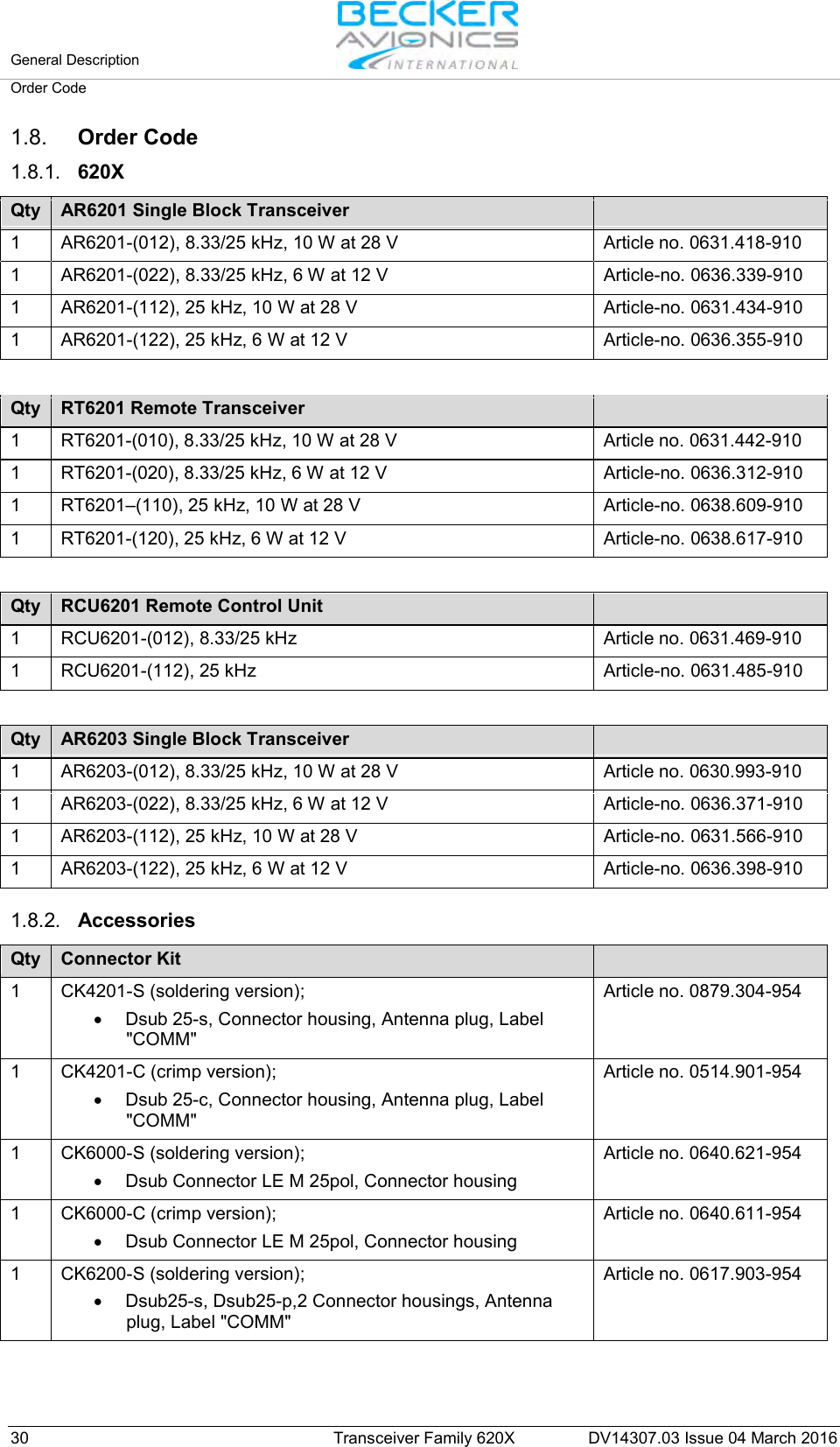

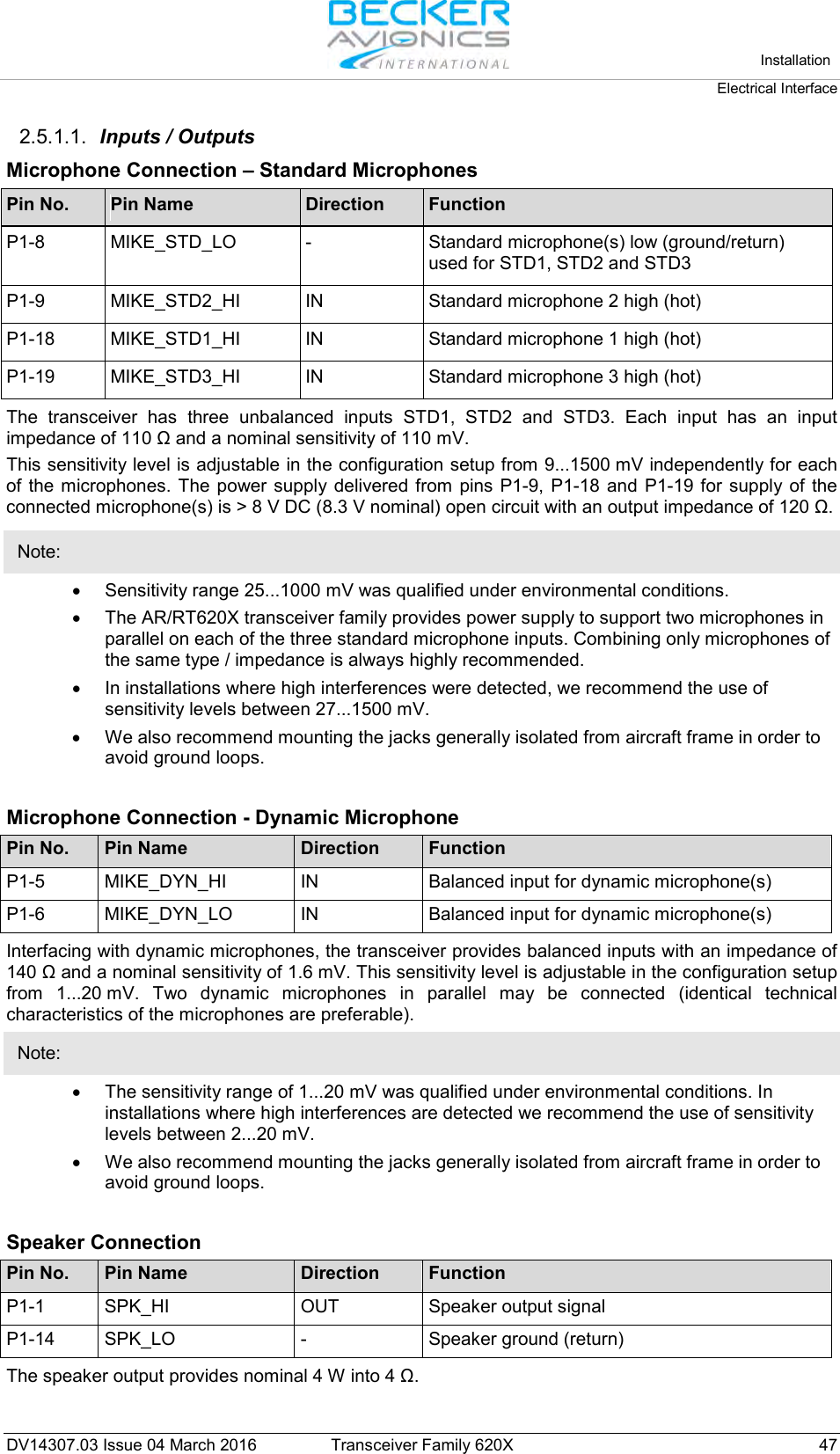
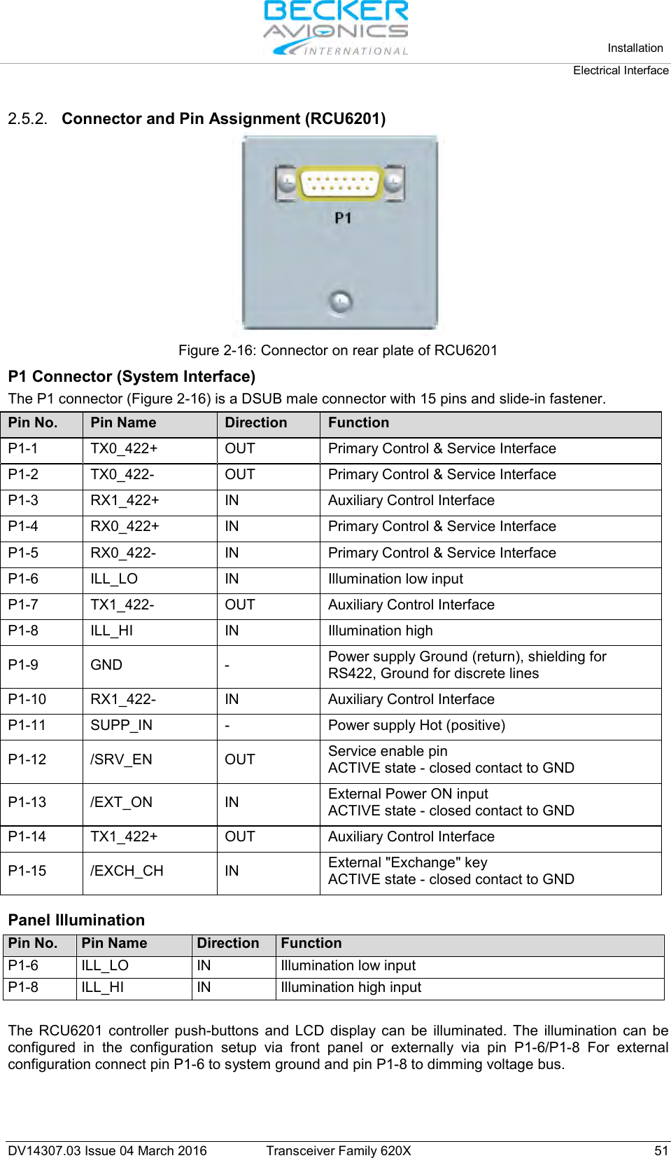
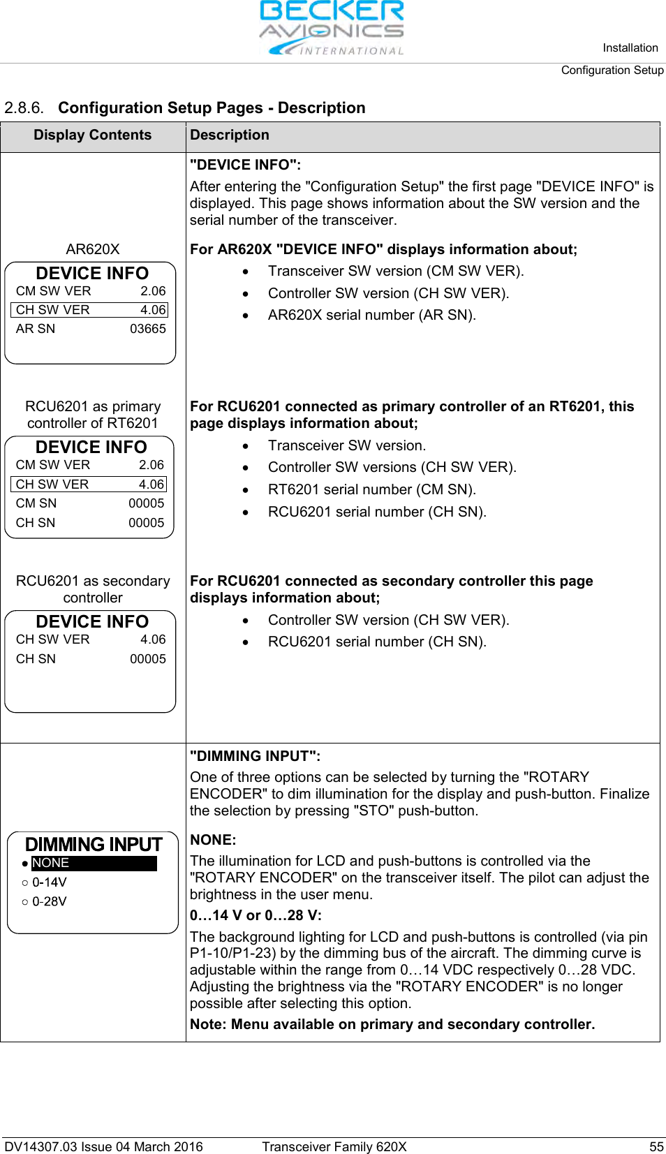
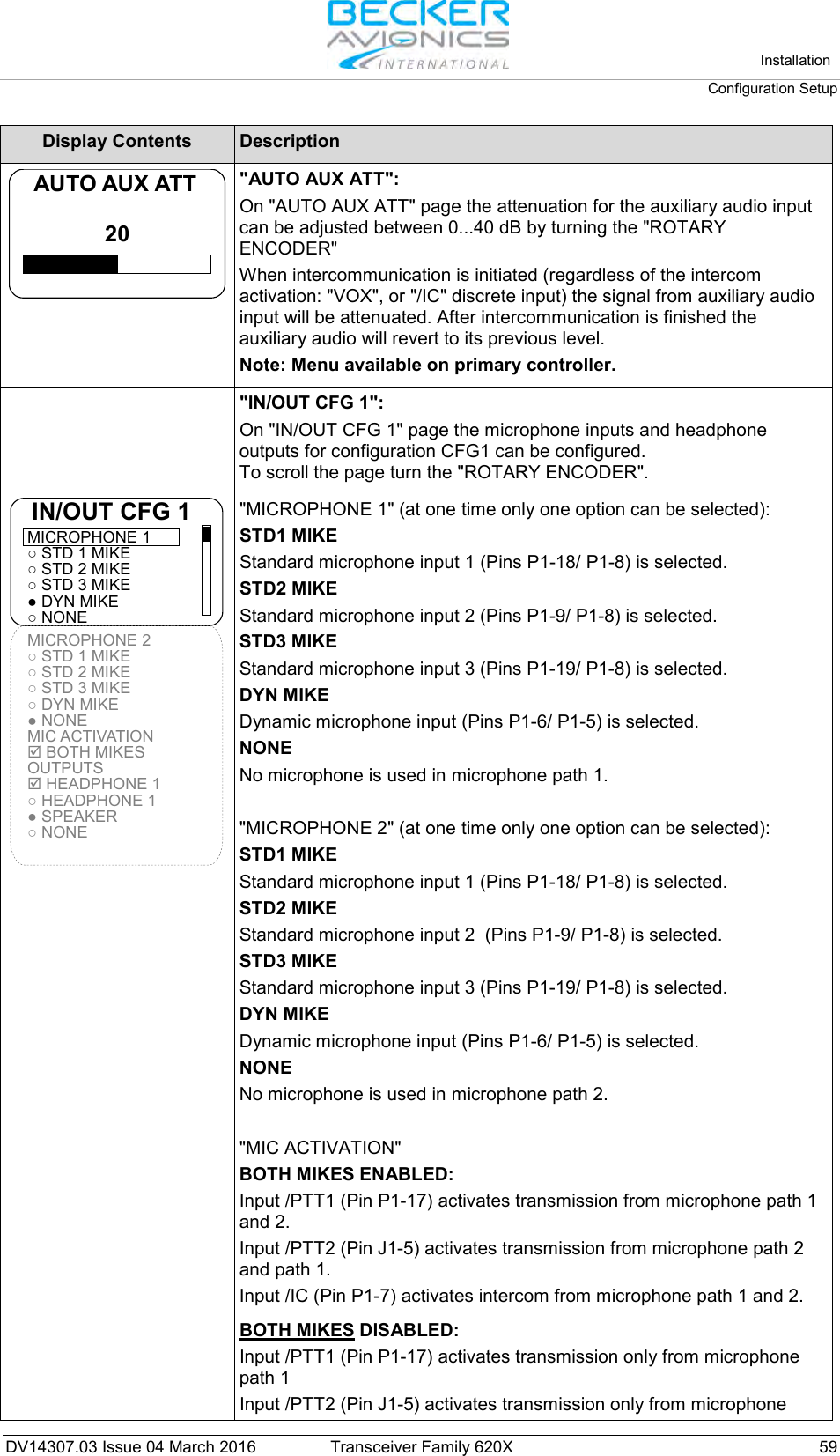
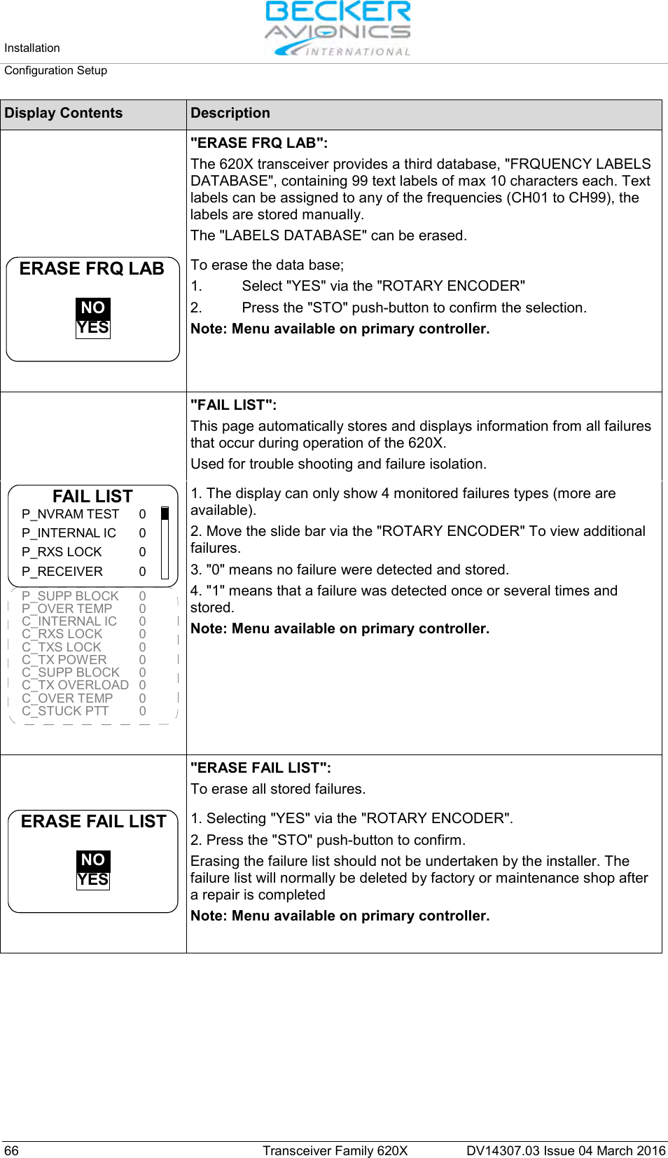
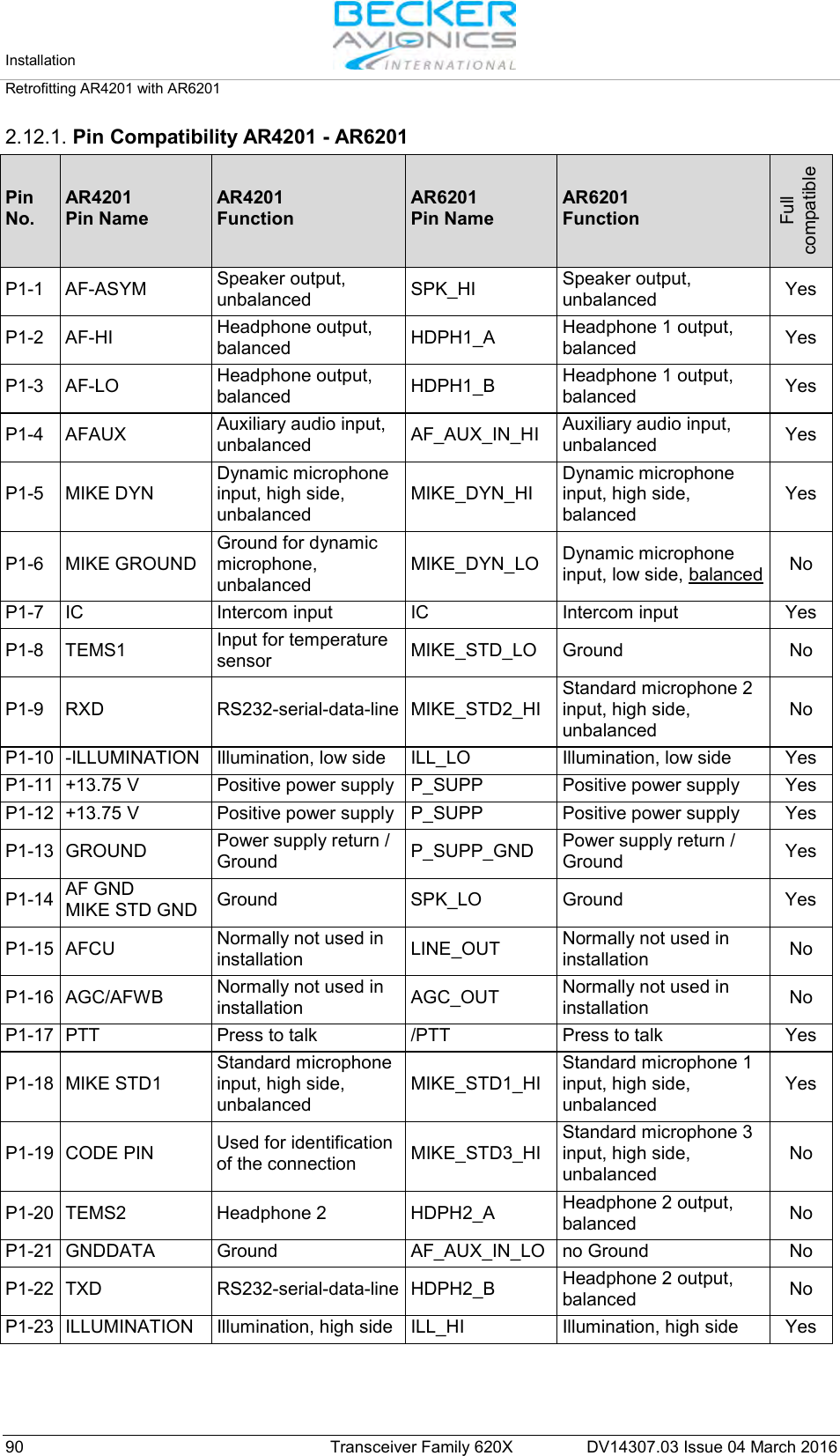
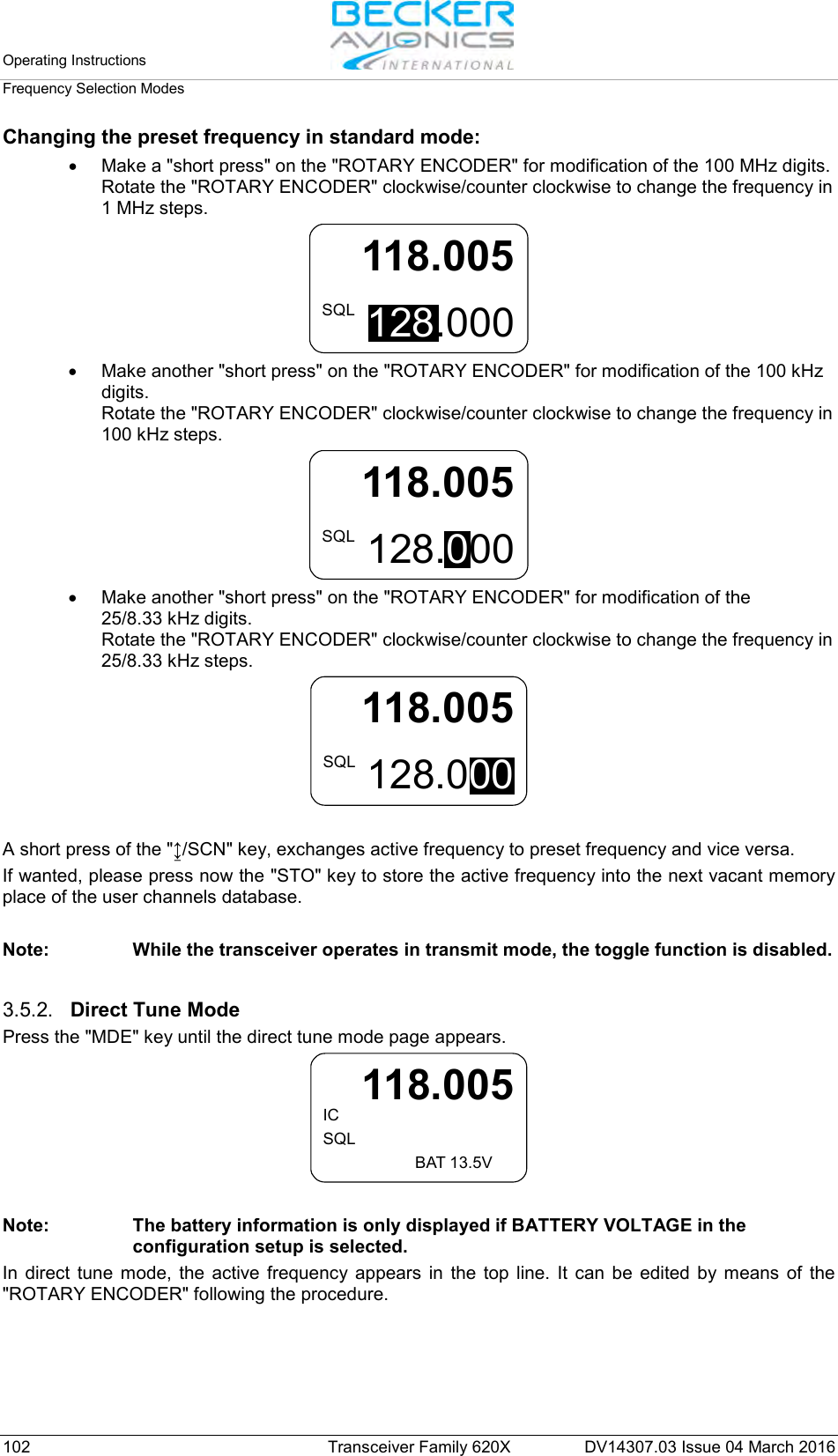
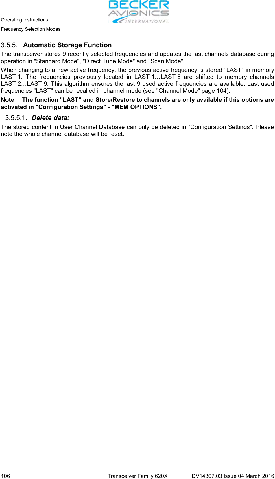
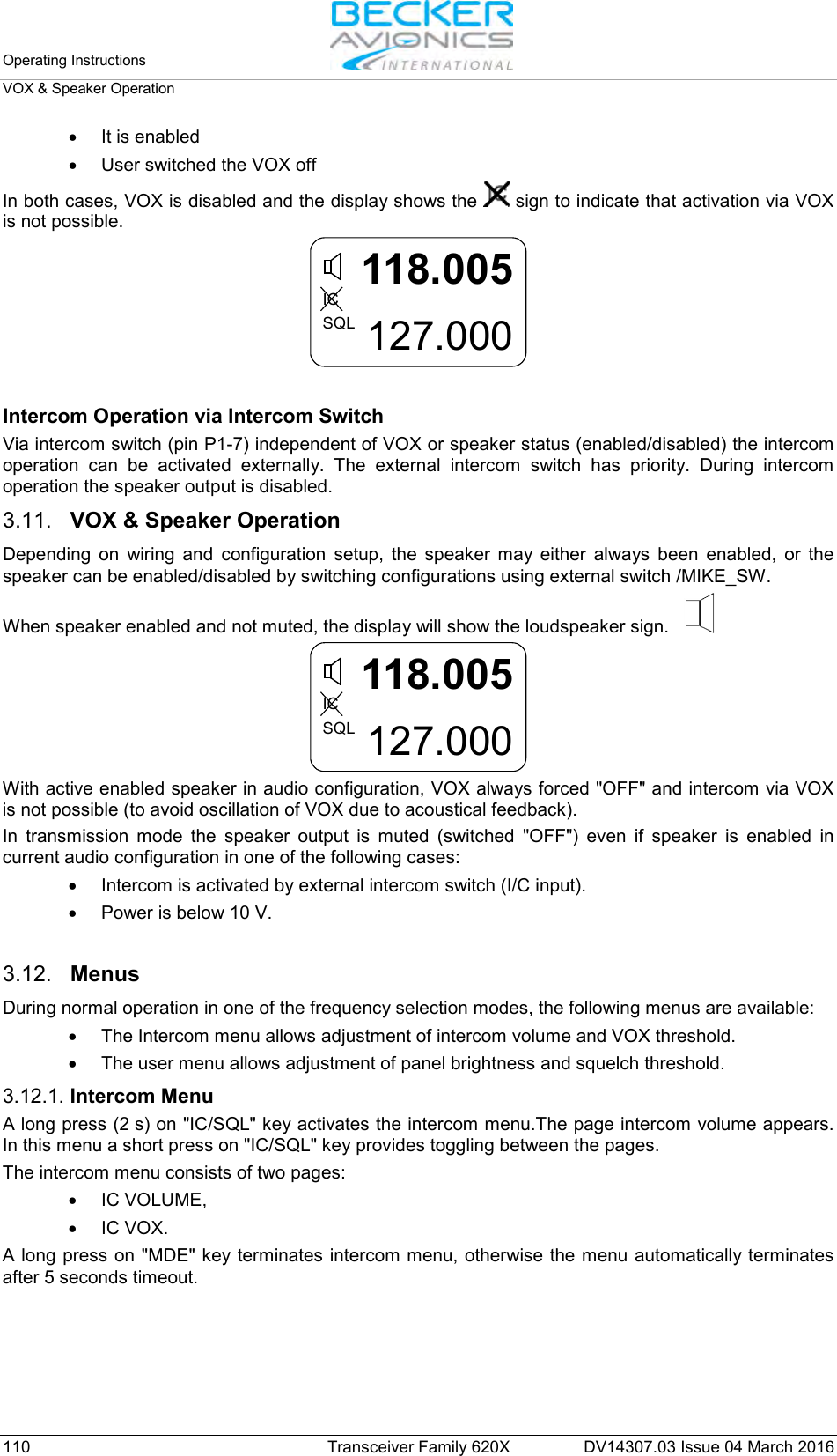
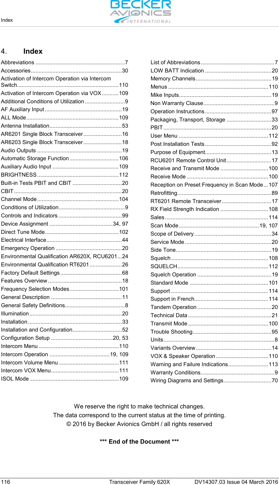
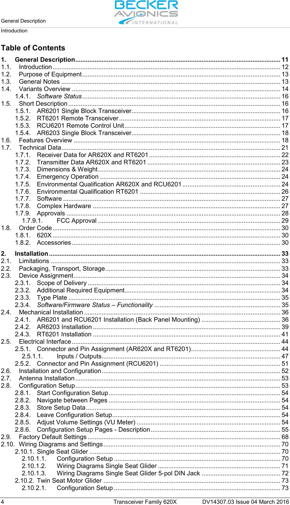
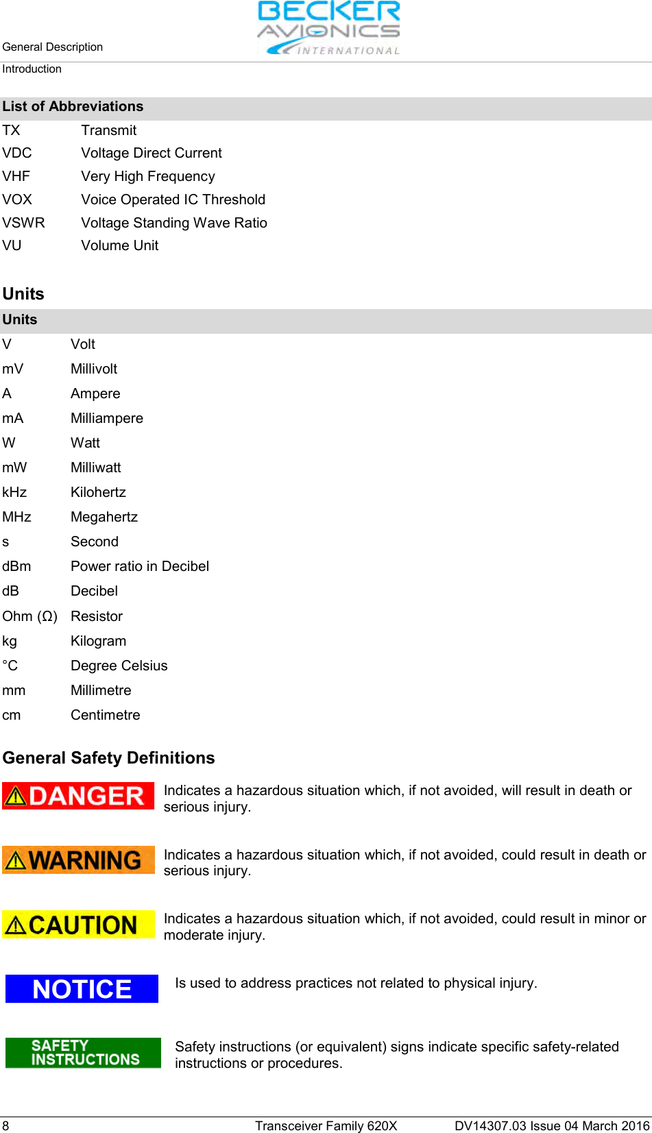
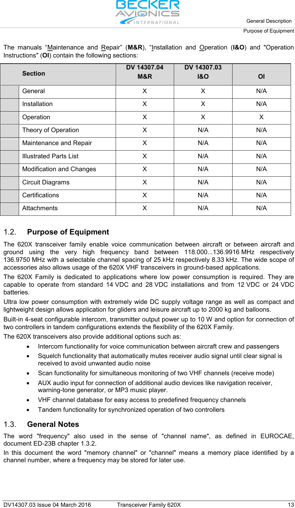
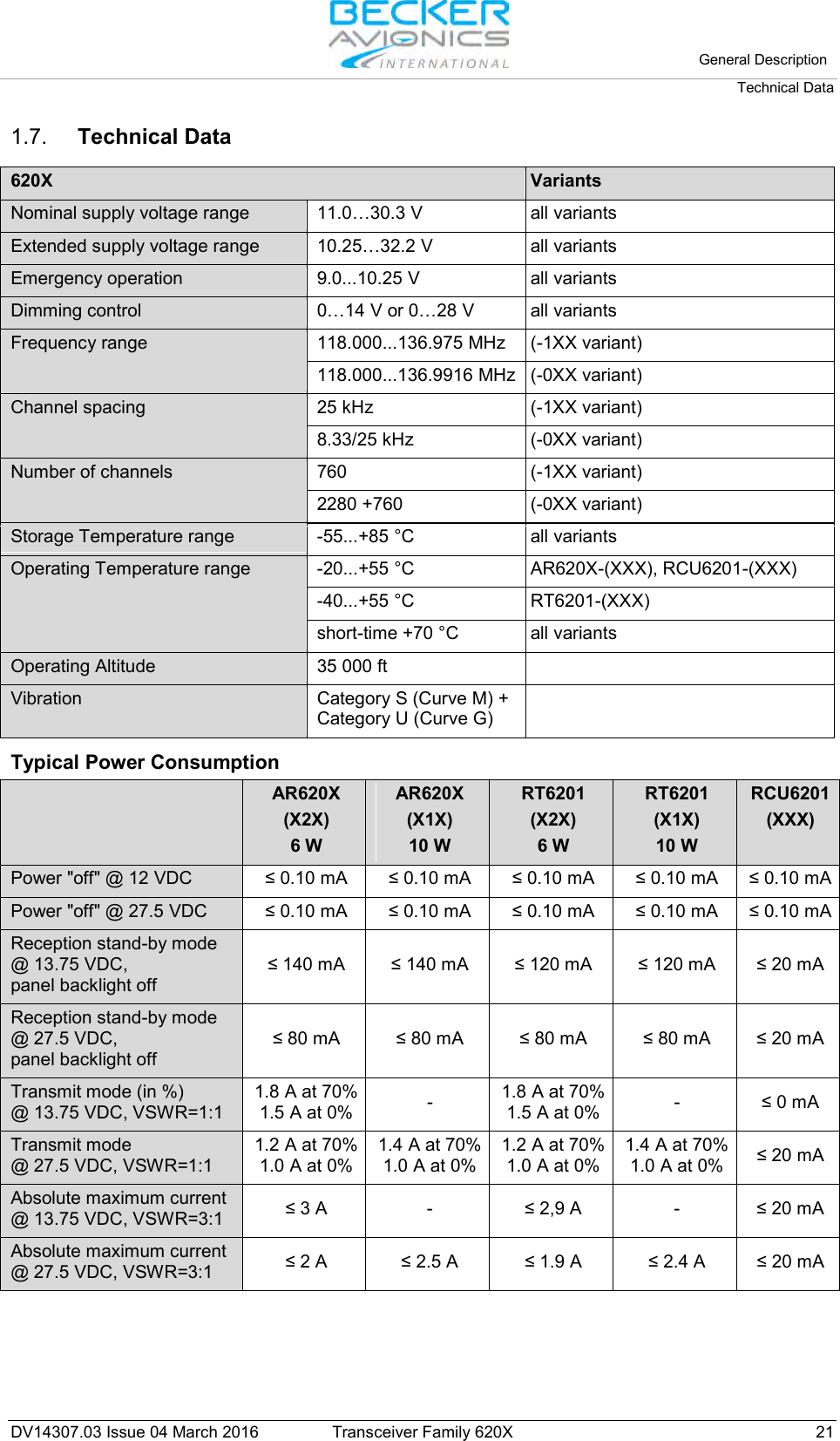
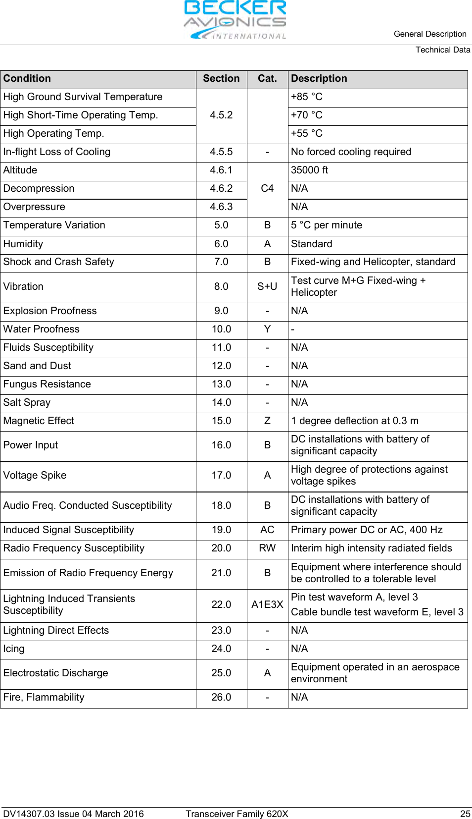
![Installation Configuration Setup 62 Transceiver Family 620X DV14307.03 Issue 04 March 2016 Display Contents Description 20 dB 150 mVVUSTD1 MIKE SENS Note: This page is only displayed if : Standard Mike 2 input is selected in IN/OUT CFG1 and MIKE_SW input pin status is [Inactive] or Standard Mike 2 input is selected in IN/OUT CFG2 and MIKE_SW input pin status is [Active]. The factory setting is 110 mV. The VU meter displays the current signal level on the audio input and also displays the highest signal value for the last 3 seconds. When speaking normally into the microphone the bar graph should remain within the recommended predefined range Note: Adjust the microphone sensitivity by keeping the cockpit noise suppression as high as possible, this will ensure correct modulation. If the sensitivity is adjusted to a smaller value (e.g. 10 mV) the cockpit noises may become louder than for a higher adjustment (e.g. 100 mV). Otherwise, adjusting the sensitivity to a very high value (e.g. 1000 mV), the cockpit noise is very much reduced, but the modulation of the transmitter might be not sufficient. The installer shall perform a communication check after modification of this parameter. Recommended is to perform this check with and without a running engine. Note: Menu available on primary controller. For installations with high interferences it is recommended to use sensitivity level 27...1500 mV.](https://usermanual.wiki/Becker-Avionics/TG660.Manual-Family/User-Guide-3110673-Page-62.png)
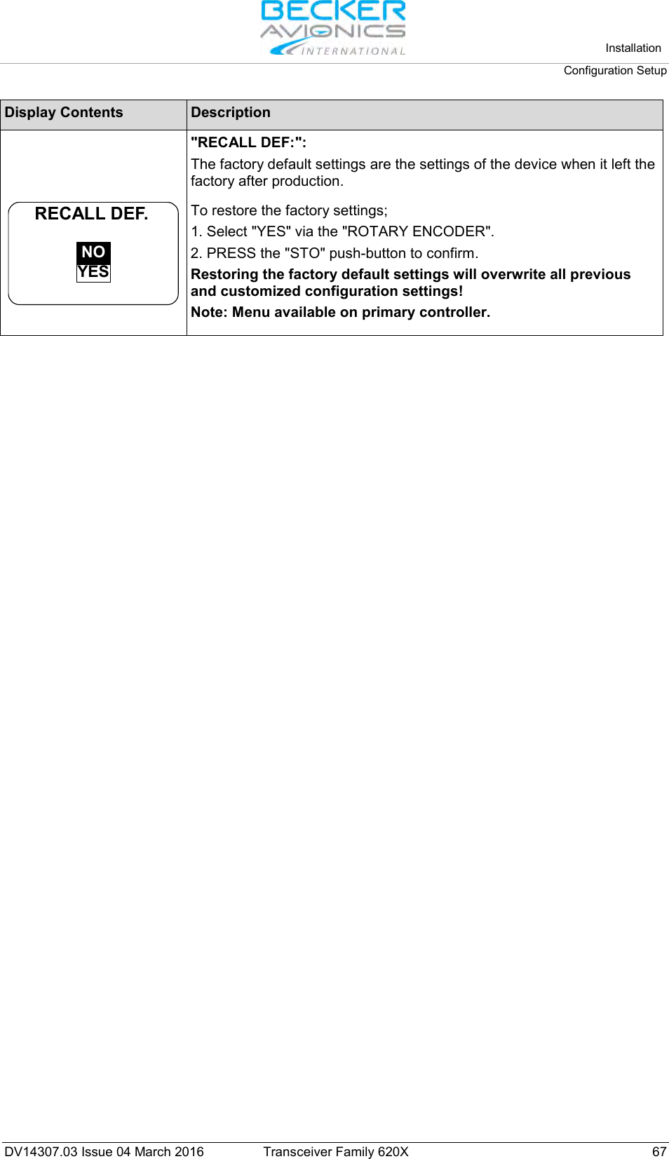
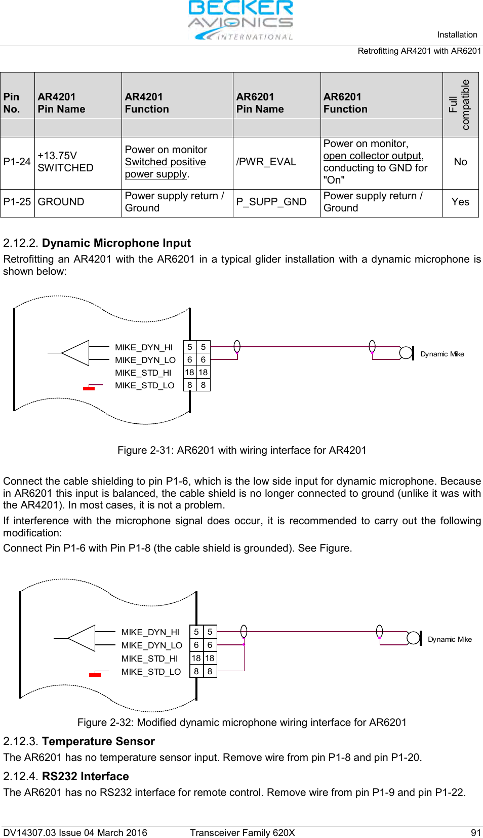
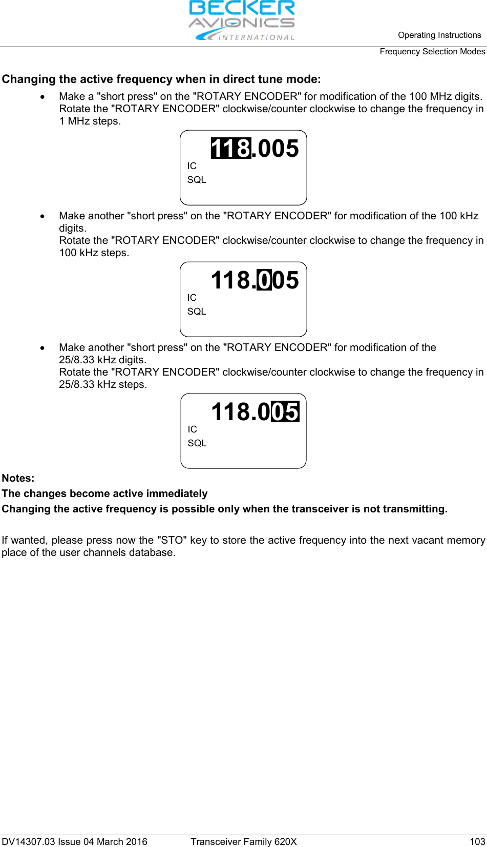
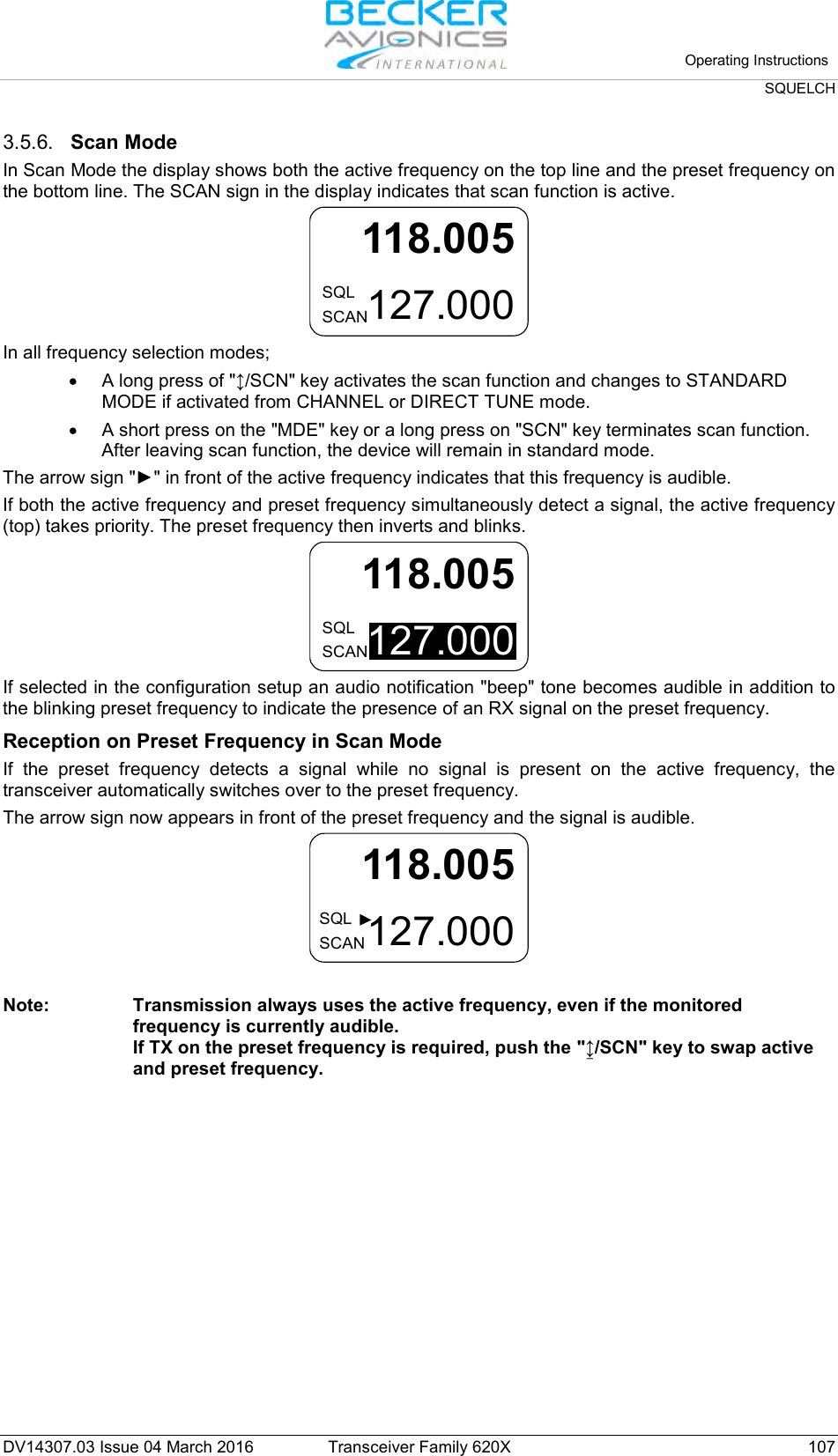
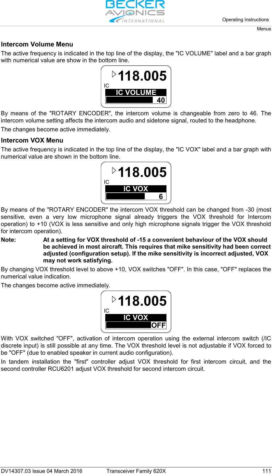
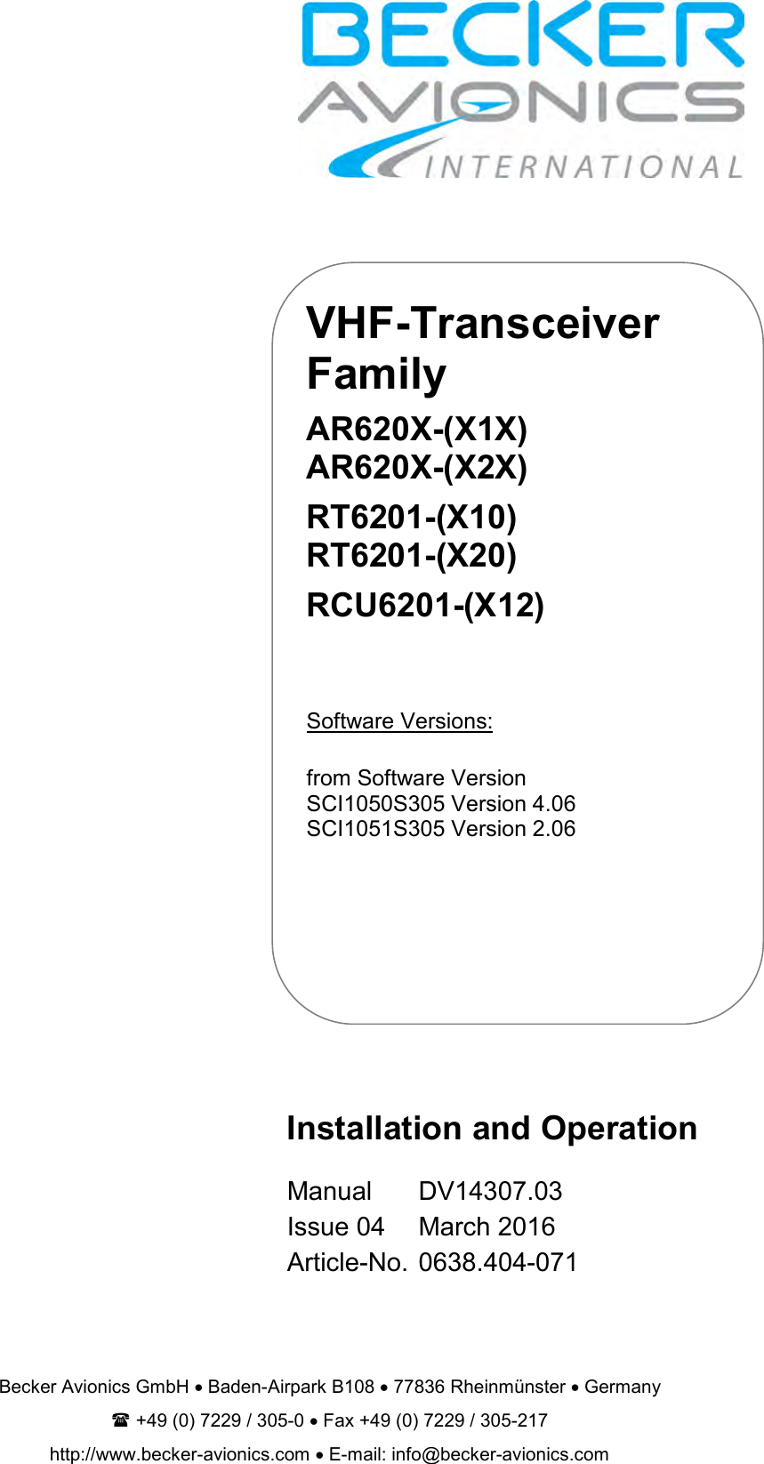
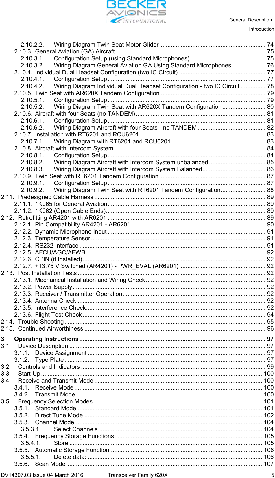
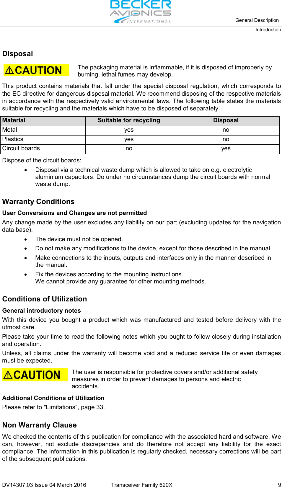
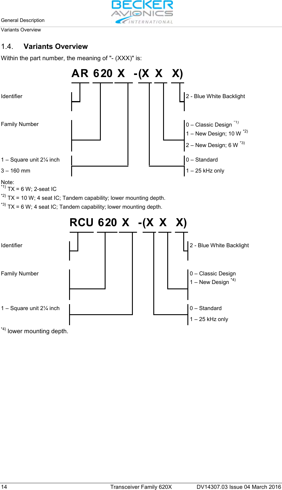
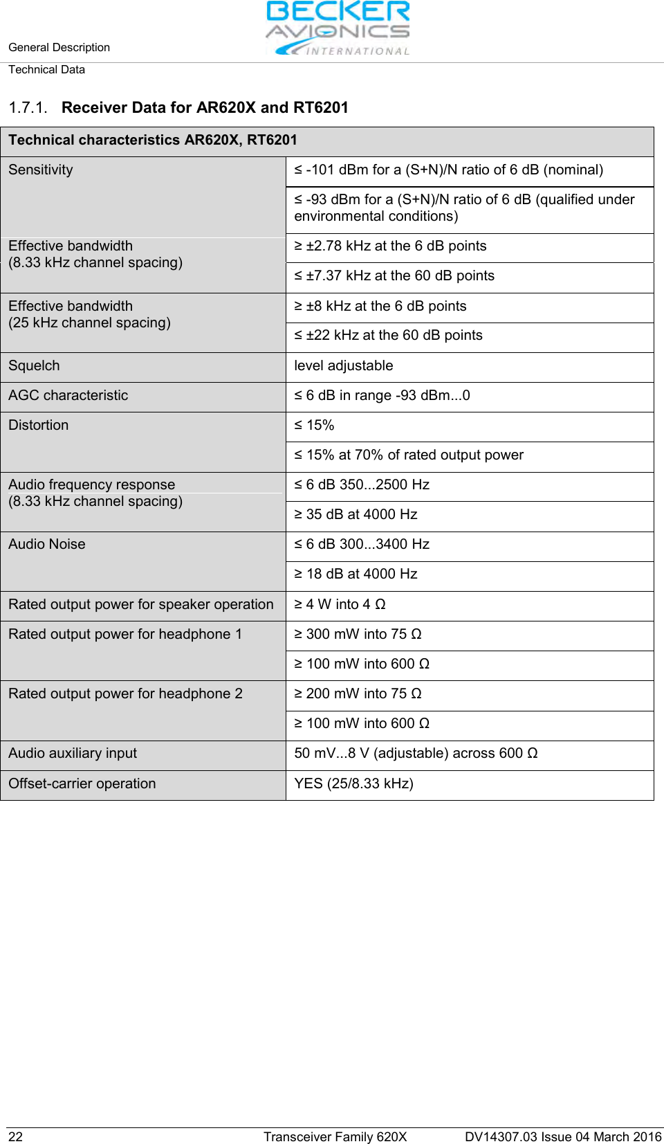
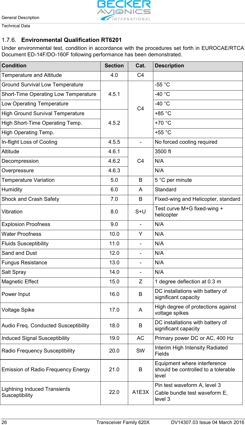
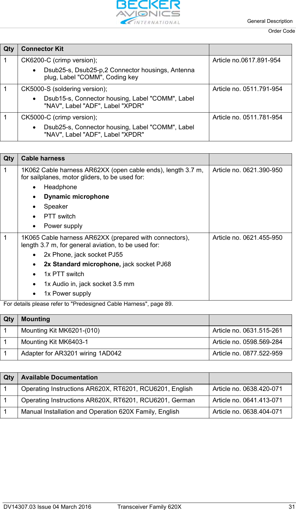
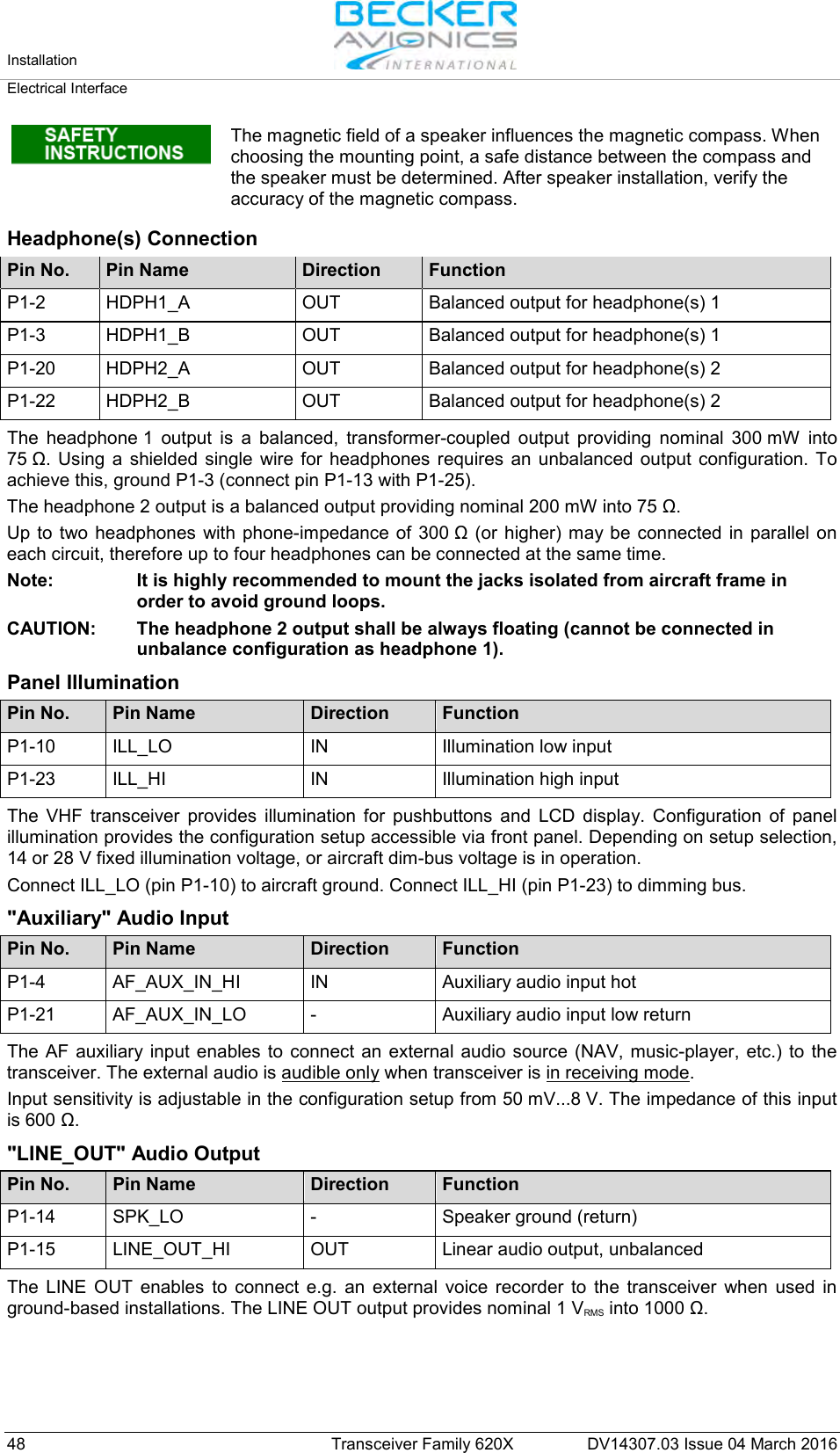
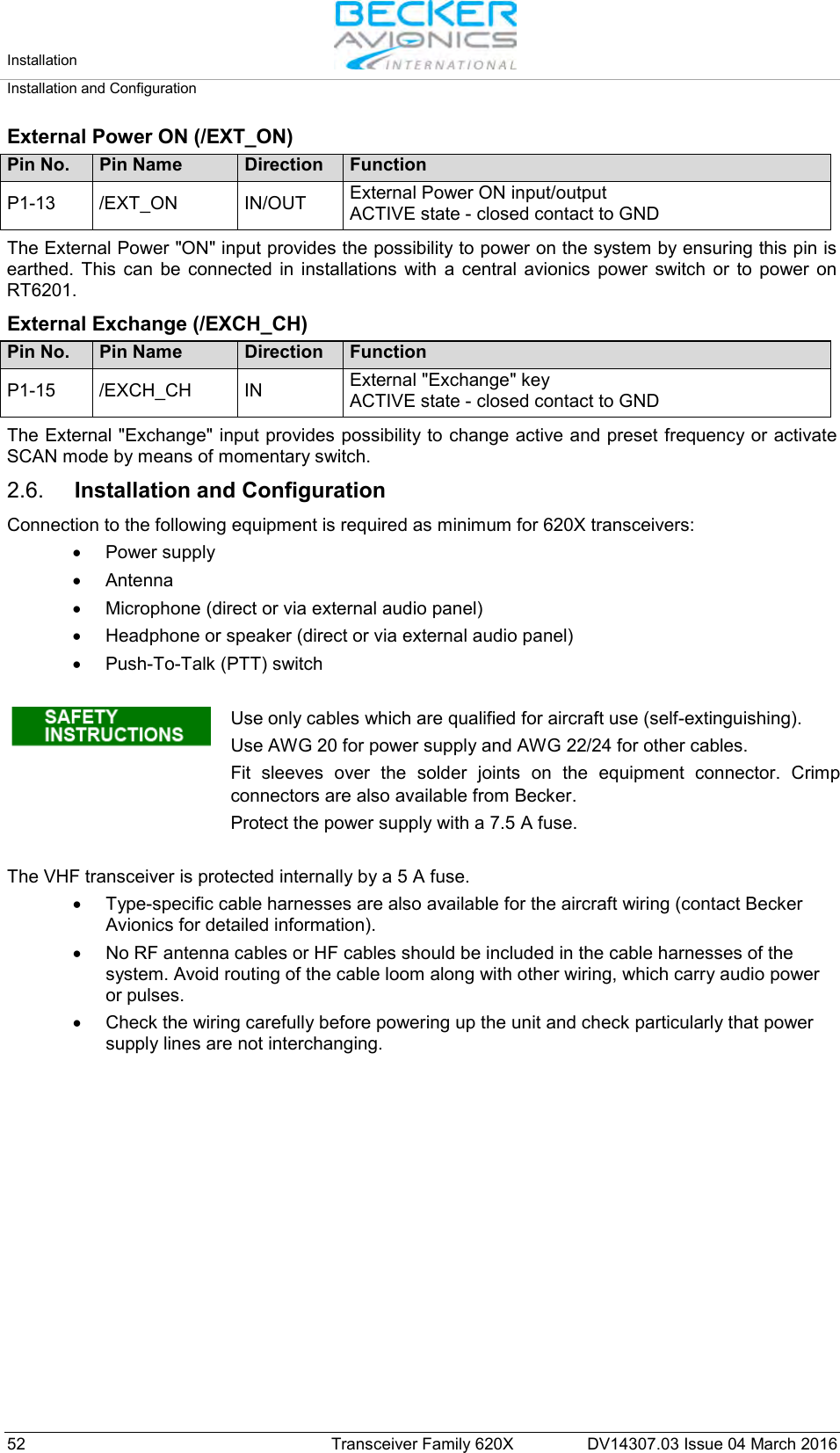
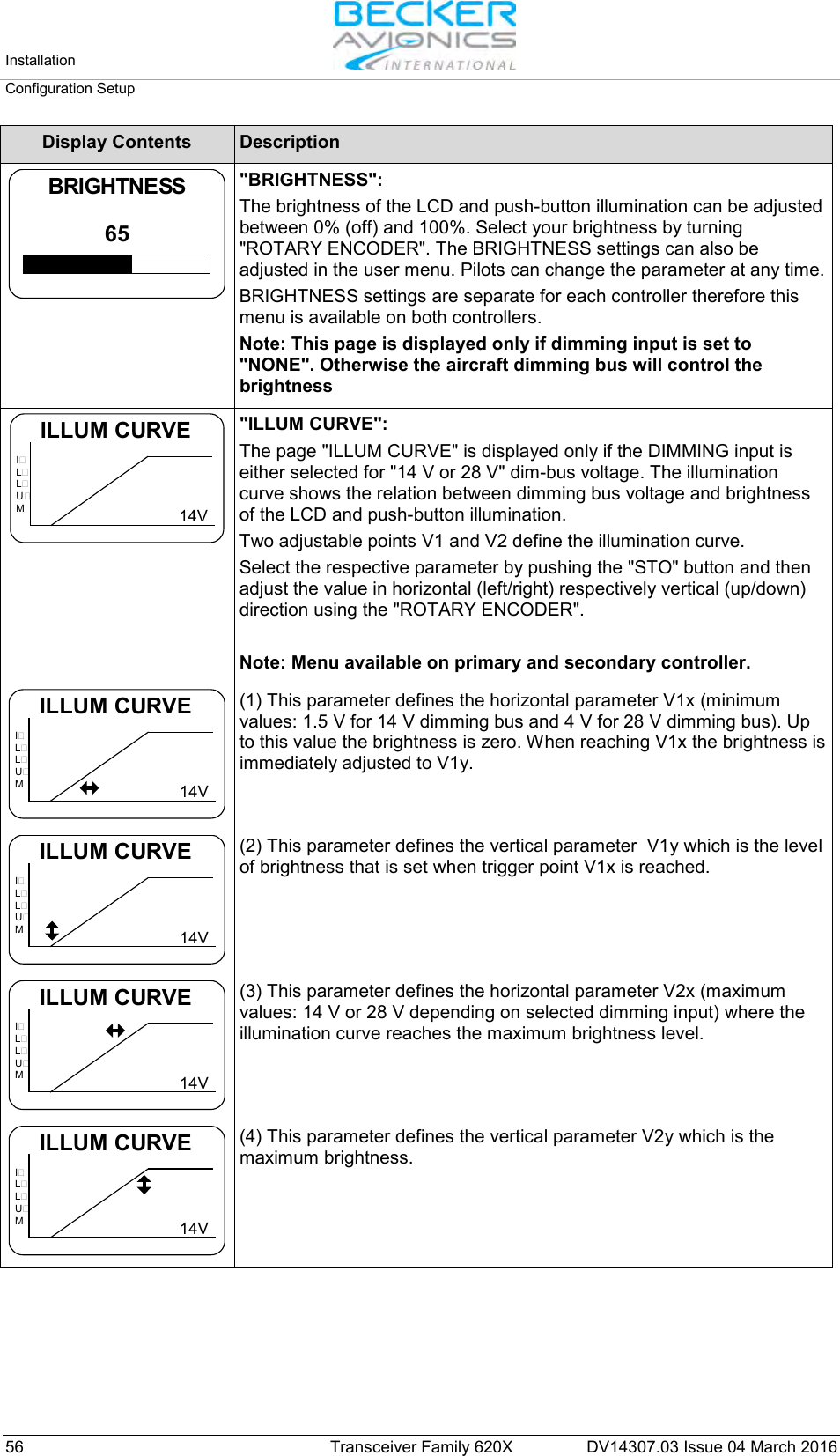
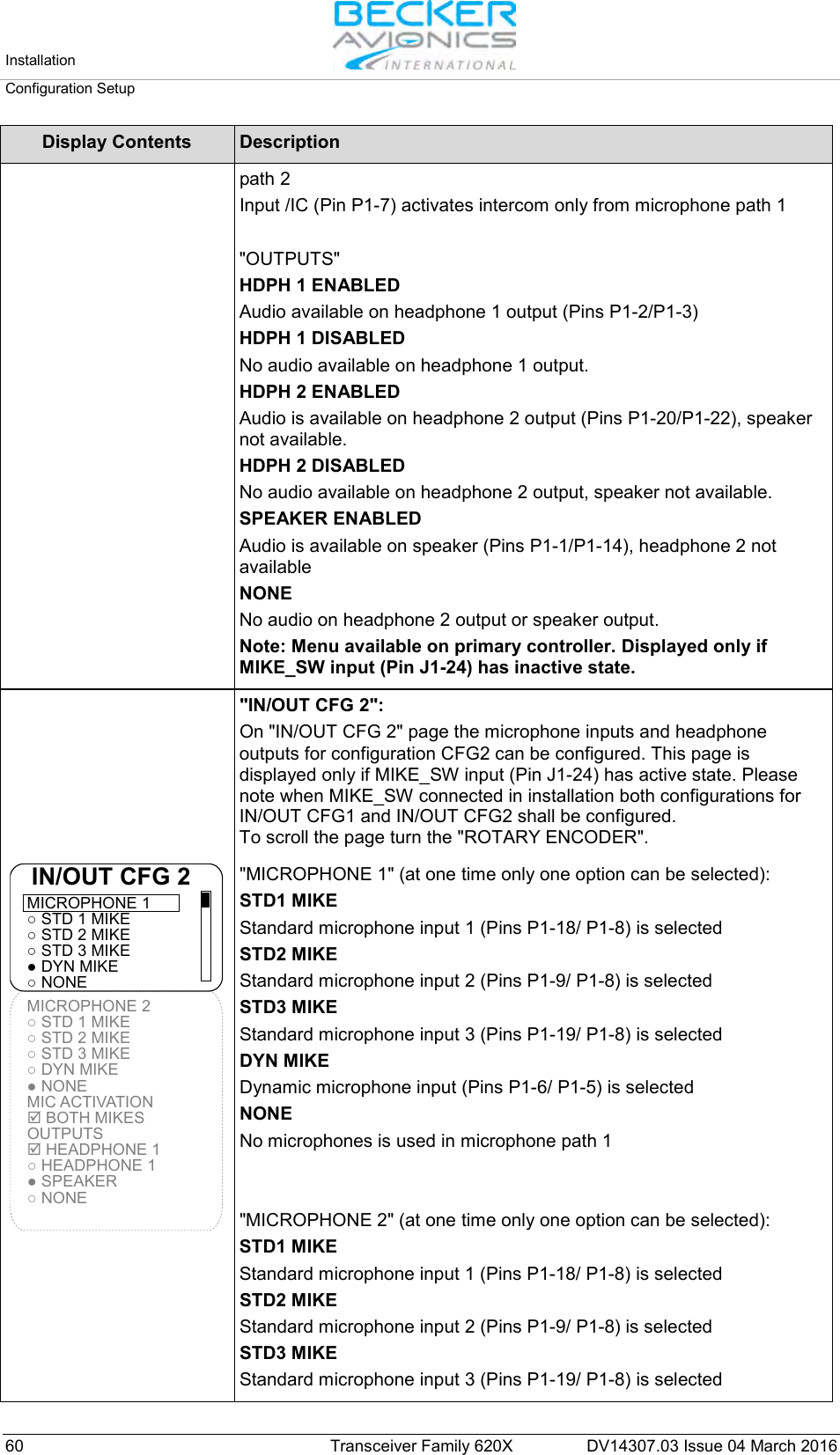
![Installation Configuration Setup DV14307.03 Issue 04 March 2016 Transceiver Family 620X 63 Display Contents Description "STD2 MIKE SENS": The sensitivity of standard microphone 2 input can be adjusted in range from 9...1500 mV by turning the "ROTARY ENCODER". 20 dB 150 mVVUSTD2 MIKE SENS Note: This page is only displayed if : Standard Mike 2 input is selected in IN/OUT CFG1 and MIKE_SW input pin status is [Inactive] or Standard Mike 2 input is selected in IN/OUT CFG2 and MIKE_SW input pin status is [Active]. The default setting is 110 mV. VU meter displays current value of audio level from standard microphone input 2 and displays the highest value of active audio level recorded during last 3 seconds. Correct sensitivity is achieved when you are speaking normally into the microphone, this is confirmed by the "Hold max level bar" remaining in "Recommended Range". Note: The microphone sensitivity shall be adjusted to achieve a correct modulation by keeping the cockpit noise suppression as high as possible. If the sensitivity value is very small (e.g. 10 mV) more cockpit noise will be heard than if the sensitivity value is set to a higher level (e.g. 100 mV). Alternatively if the sensitivity value is very high (e.g. 1000 mV) the cockpit noise will significantly be reduced but the modulation of the transmitter may not be sufficient. After modifying this parameter a communication check shall be done by the installer. It is recommended to perform this communication check with and without engine running. Note: Menu available on primary controller. For installations with high interference it is recommended to use sensitivity level 27...1500 mV. "STD3 MIKE SENS": The sensitivity of standard microphone 3 Input can be adjusted in range from 9...1500 mV by turning the "ROTARY ENCODER". 20 dB 150 mVVUSTD3 MIKE SENS Note: This page is only displayed if : Standard Mike 3 input is selected in IN/OUT CFG1 and MIKE_SW input pin status is [Inactive] or Standard Mike 3 input is selected in IN/OUT CFG2 and MIKE_SW input pin status is [Active]. The default setting is 110 mV. VU meter displays current value of audio level from standard microphone input 3 and displays the highest value of active audio level recorded during last 3 seconds. Correct sensitivity is achieved when you are speaking normally into the microphone, this is confirmed by the "Hold max level bar" remaining in "Recommended Range". Note: The microphone sensitivity shall be adjusted to achieve a correct modulation by keeping the cockpit noise suppression as high as possible. If the sensitivity value is very small (e.g. 10 mV) more cockpit noise will be heard than if the sensitivity value is set to a higher level (e.g. 100 mV). Alternatively if the sensitivity value is very high (e.g. 1000 mV) the cockpit noise will significantly be reduced but the modulation of the transmitter may not be sufficient. After modifying this parameter a communication check shall be done by the installer. It is recommended to perform this communication check with and without engine running. Note: Menu available on primary controller. For installations with high interferences it is recommended to use sensitivity level 27...1500 mV.](https://usermanual.wiki/Becker-Avionics/TG660.Manual-Family/User-Guide-3110673-Page-63.png)
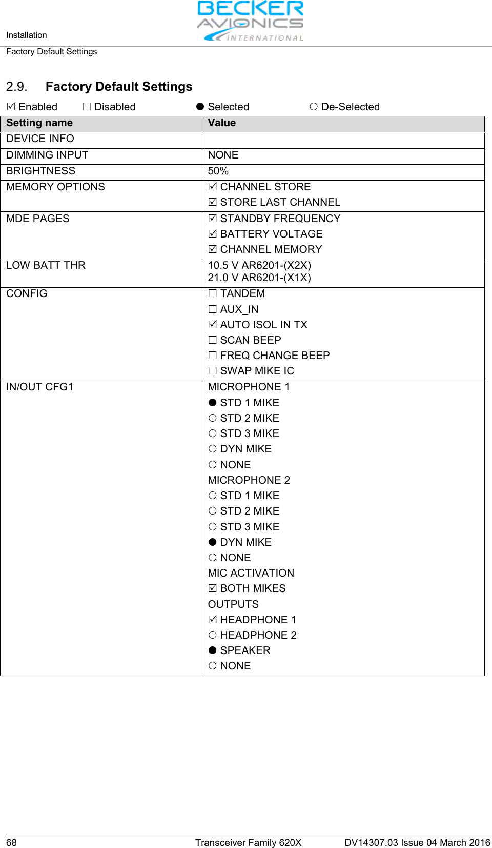
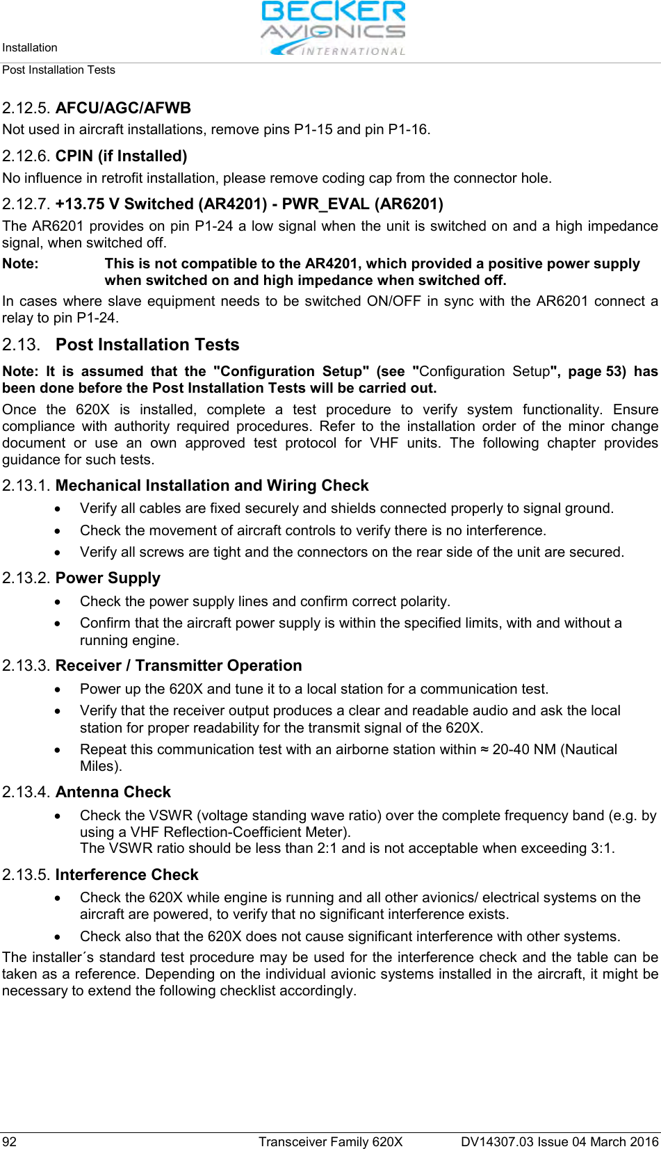
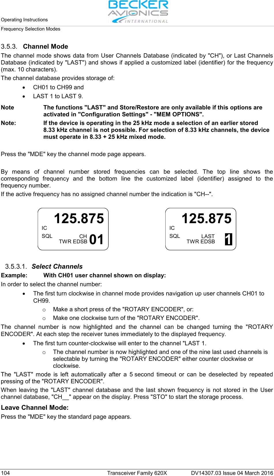
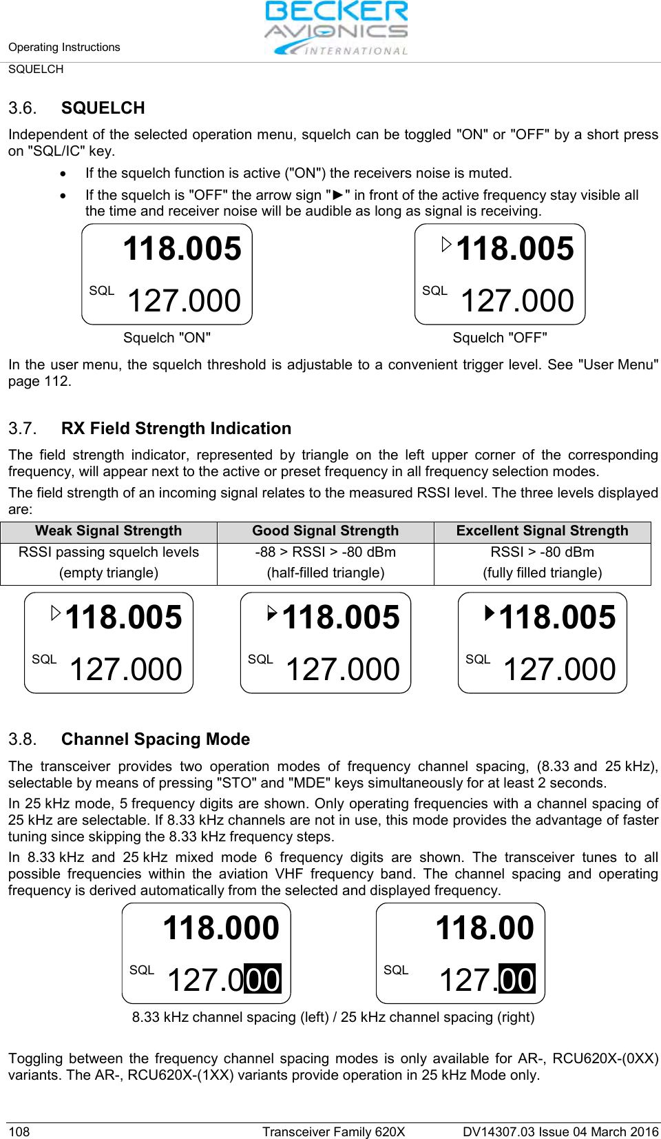
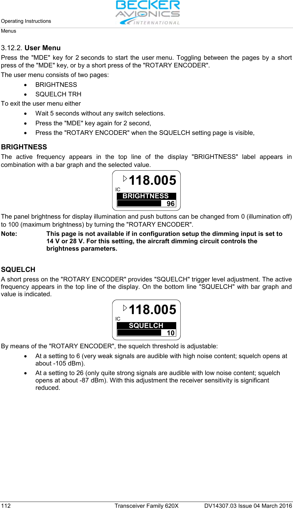
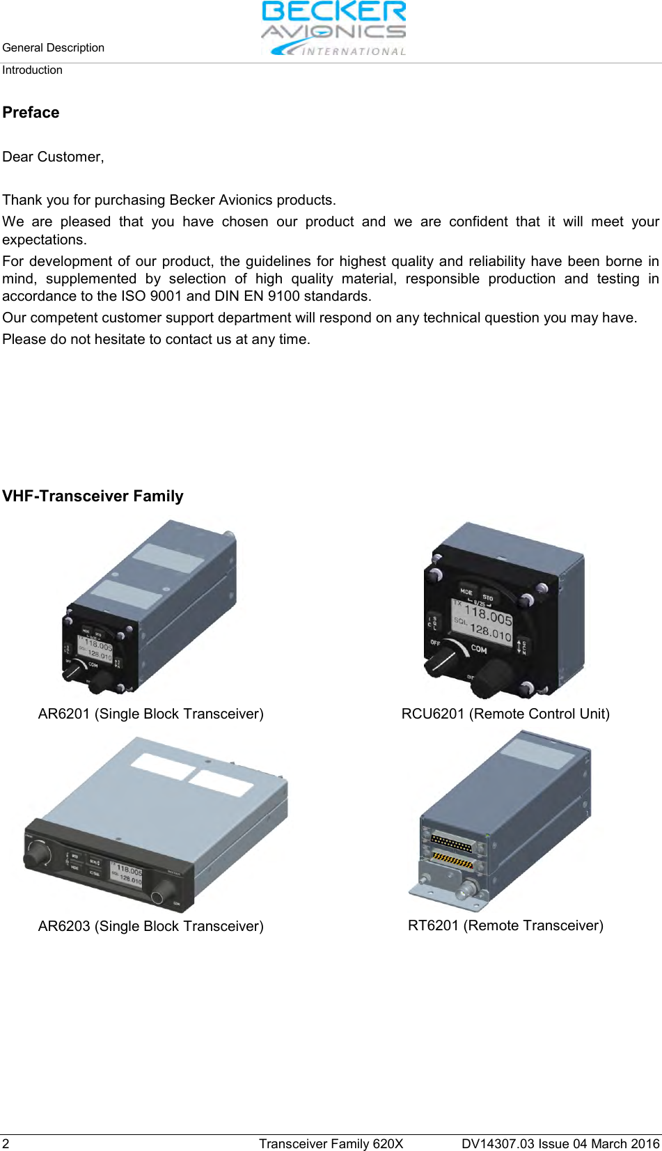
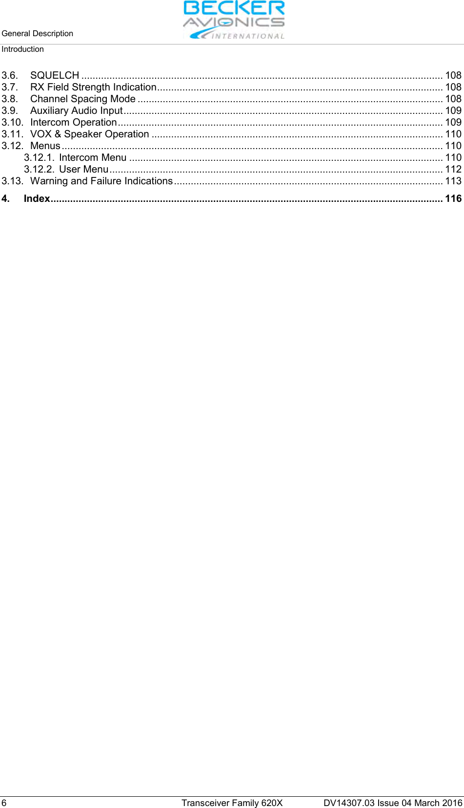
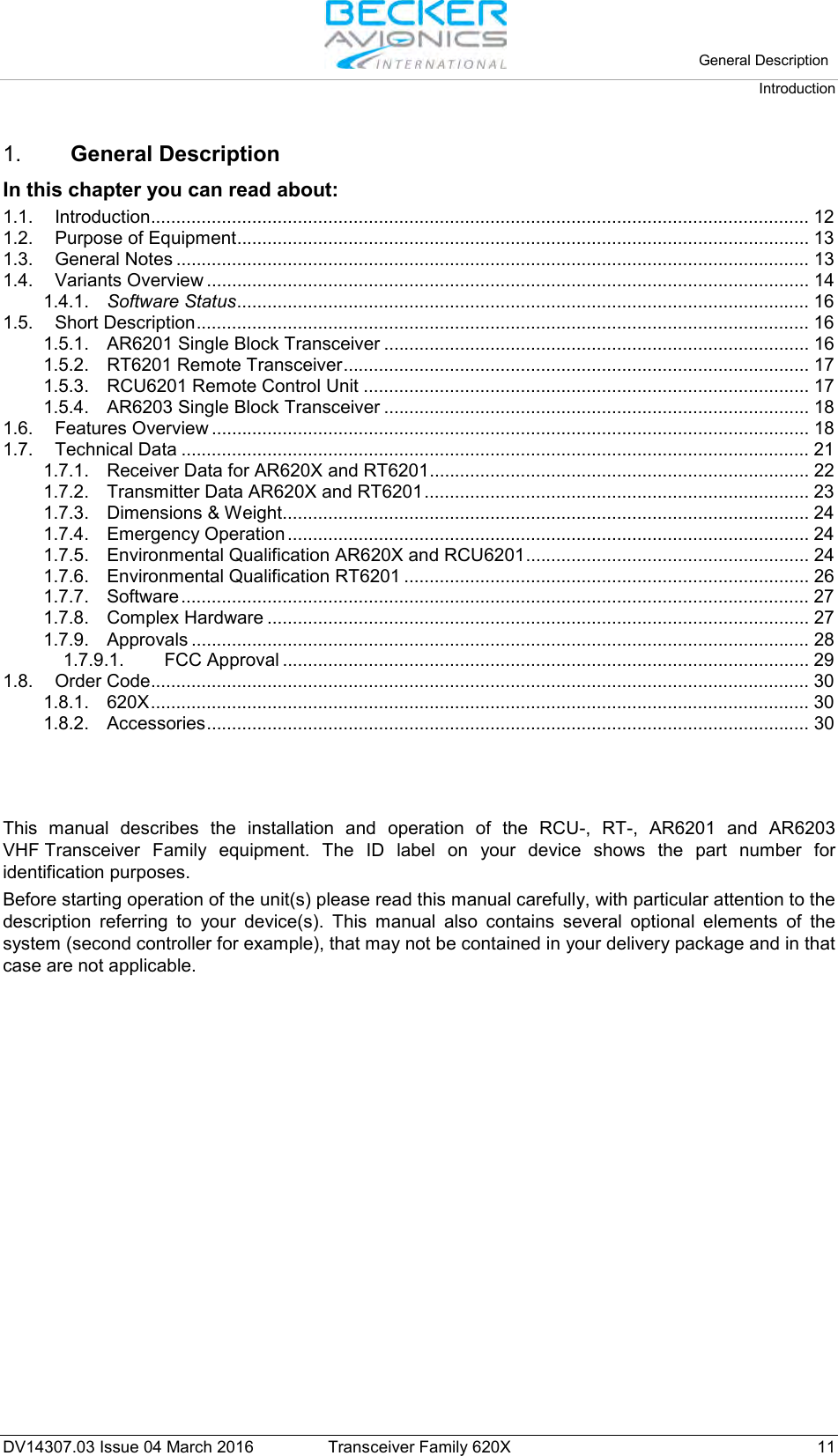
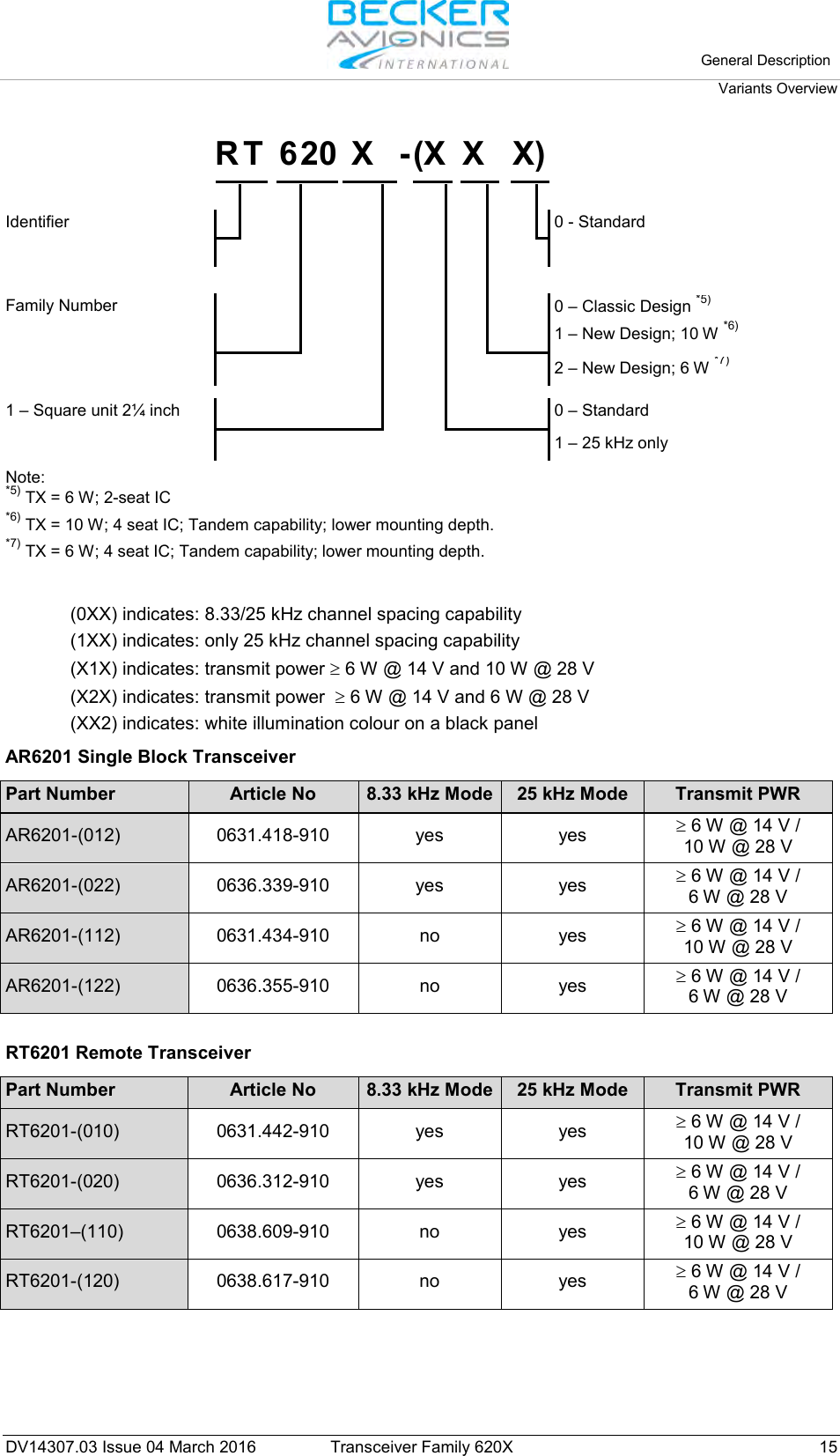
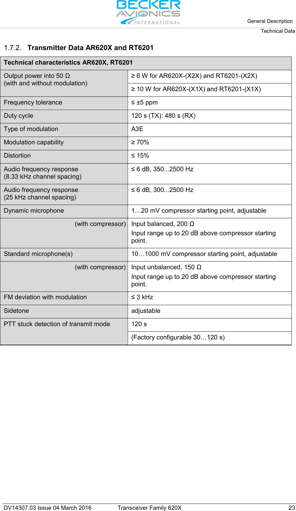
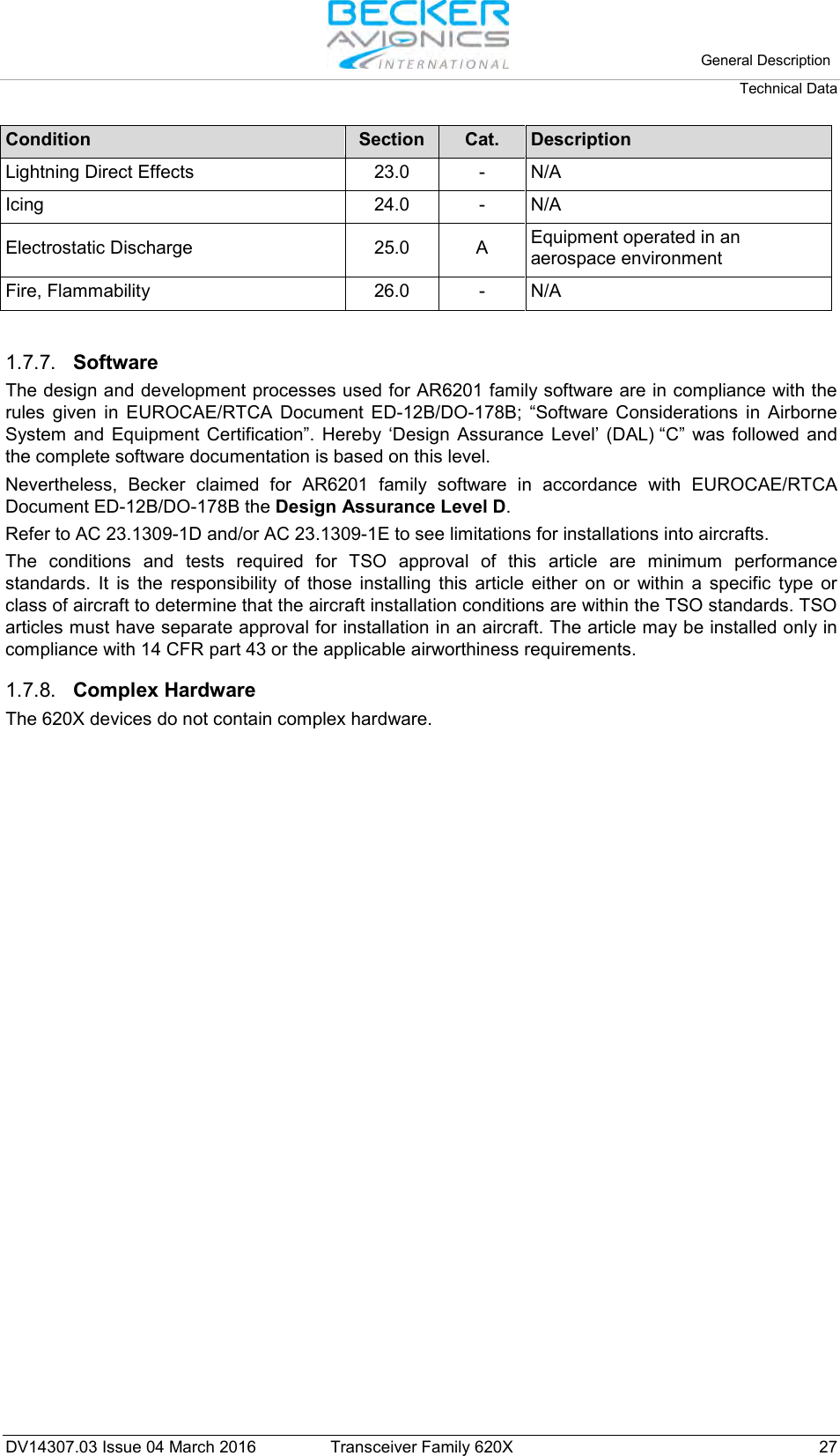
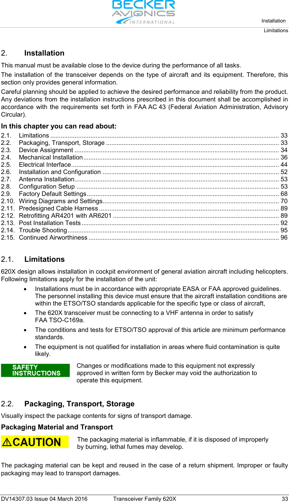
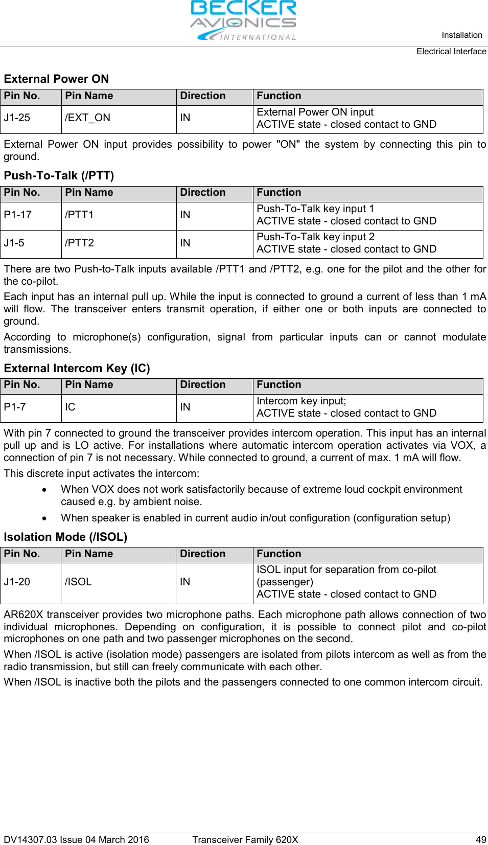
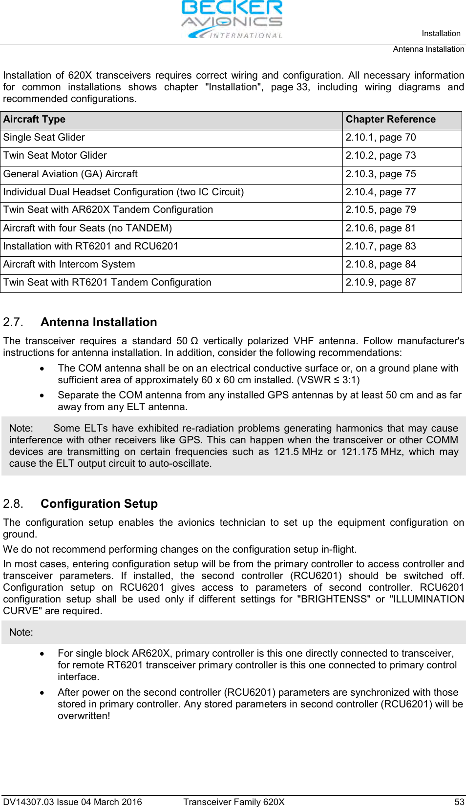
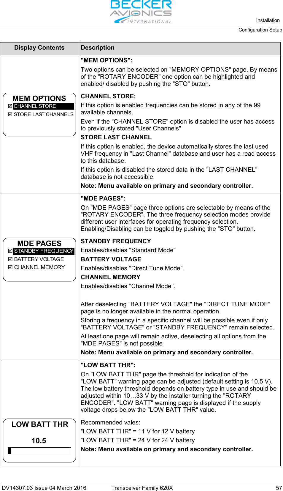
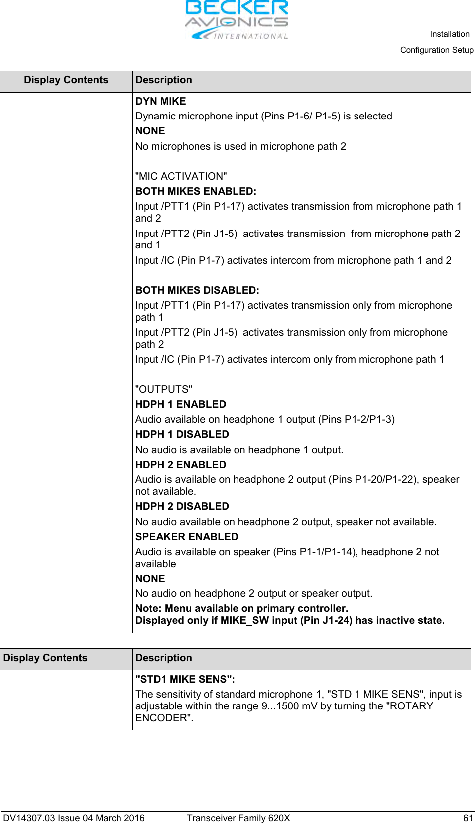
![Installation Configuration Setup 64 Transceiver Family 620X DV14307.03 Issue 04 March 2016 Display Contents Description "DYN MIKE SENS": The sensitivity of the Dynamic Mike, "DYN MIKE SENS", input is adjustable within a range of 0.5...25 mV by turning the "ROTARY ENCODER". 17 dB 3.5 mVVUDYN MIKE SENS Note: This page is only displayed if : Dynamic input is selected in IN/OUT CFG1 and MIKE_SW input pin status is [Inactive] or Dynamic Mike input is selected in IN/OUT CFG2 and MIKE_SW input pin status is [Active]. The factory setting is 3.5 mV. When speaking normally into the microphone the bar graph should remain within the recommended predefined range Note: The microphone sensitivity shall be adjusted to achieve a correct modulation by keeping the cockpit noise suppression as high as possible. If the sensitivity is adjusted to a smaller value (e.g. 1 mV) the cockpit noises may become louder than for a higher adjustment (e.g. 25 mV). Otherwise, adjusting the sensitivity to a very high value (e.g 25 mV), the cockpit noise is significantly reduced but the modulation of the transmitter may not be sufficient. The installer shall perform a communication check after modification of this parameter. Recommended is to perform this check with and without a running engine. Note: Menu available on primary controller. For installations with high interferences it is recommended to use sensitivity level 2...25 mV. "SPKR VOL SRC": One of the three following options may be selected for speaker volume source, "SPKR VOL SRC", by pressing the "STO" button: SPKR VOL SRCRY CHRY CH PRIMARY CH If "PRIMARY CH" is selected the speaker volume will be adjustable by AR6201-(X0X). SECONDARY CH If "SECONDARY CH" is selected the speaker volume will be adjustable by RCU6201. BOTH If "BOTH" is selected the speaker volume will be adjustable by the arithmetic average value from AR620X and RCU6201. Note: Menu available on primary controller. If optional second controller (RCU6201) is not available then SPKR VOLUME SOURCE shall be set to the PRIMARY CH "SQUELCH THR": The noise squelch threshold "SQUELCH THR" is adjustable within a range of 6...26 by turning the "ROTARY ENCODER". 6SQUELCH THR Minimum Adjustment of 6 means: Weak RF signals can trigger the Squelch threshold and the voice signal might be low combined with a noisy background. Maximum adjustment of 26 means: Only strong RF signals will trigger the Squelch threshold. The voice signal will be audible very clear with very low background noise. Weak RF signals may not trigger the Squelch threshold and therefore the audio may not be heard by the pilots. Note: Adjustment of the "SQUELCH THR" is available via the user menu at any time.](https://usermanual.wiki/Becker-Avionics/TG660.Manual-Family/User-Guide-3110673-Page-64.png)