Becker Avionics TG660 Aircraft Radio User Manual TG660
Becker Avionics, Inc. Aircraft Radio TG660
UserManual.wiki
>
Becker Avionics
>
TG660 User Manual
>
User Manual
Contents
1.
Manual_Family
2.
Manual_PA3-2AB-AIR
3.
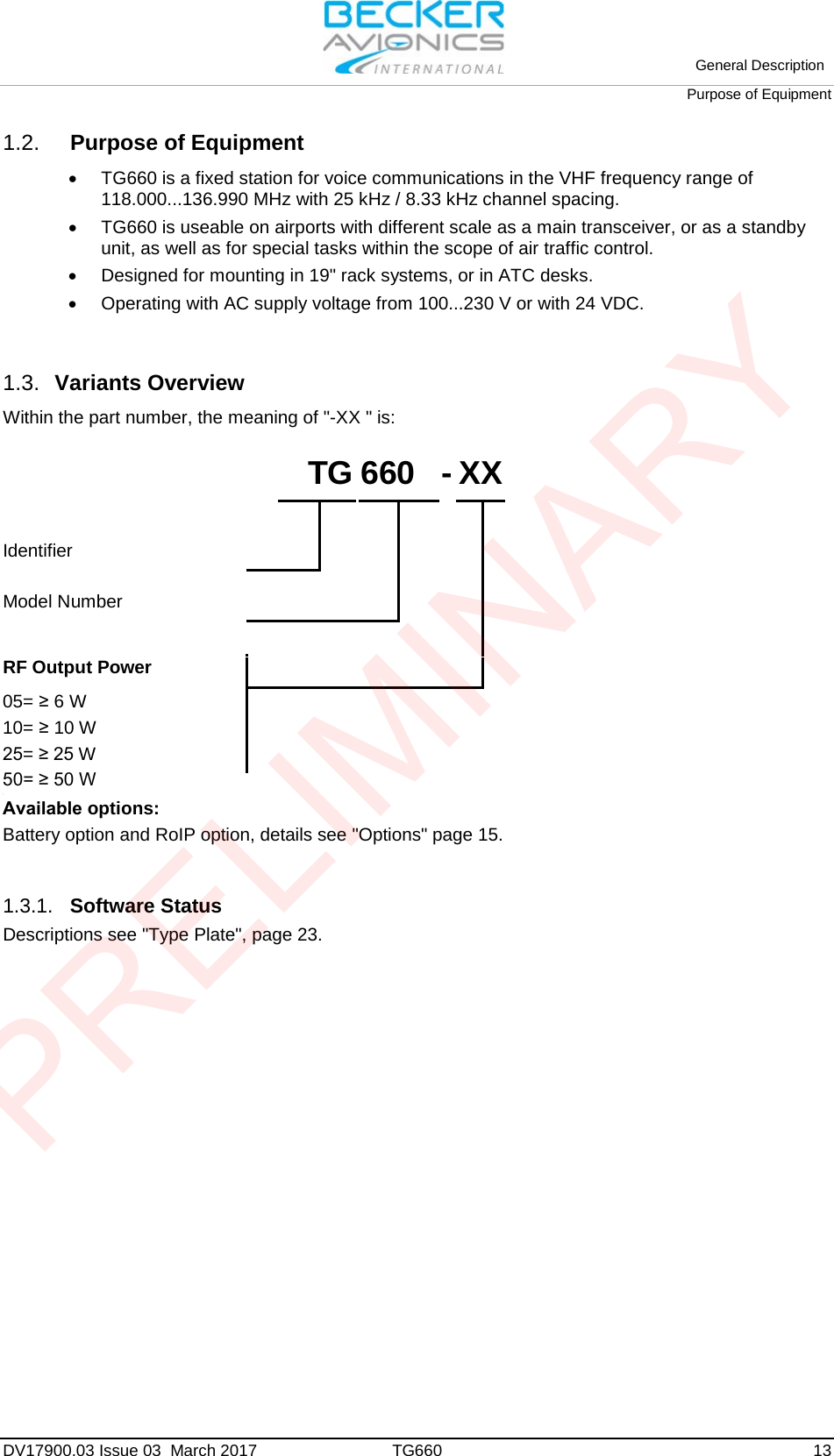
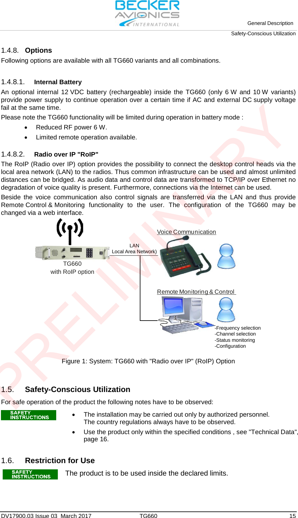
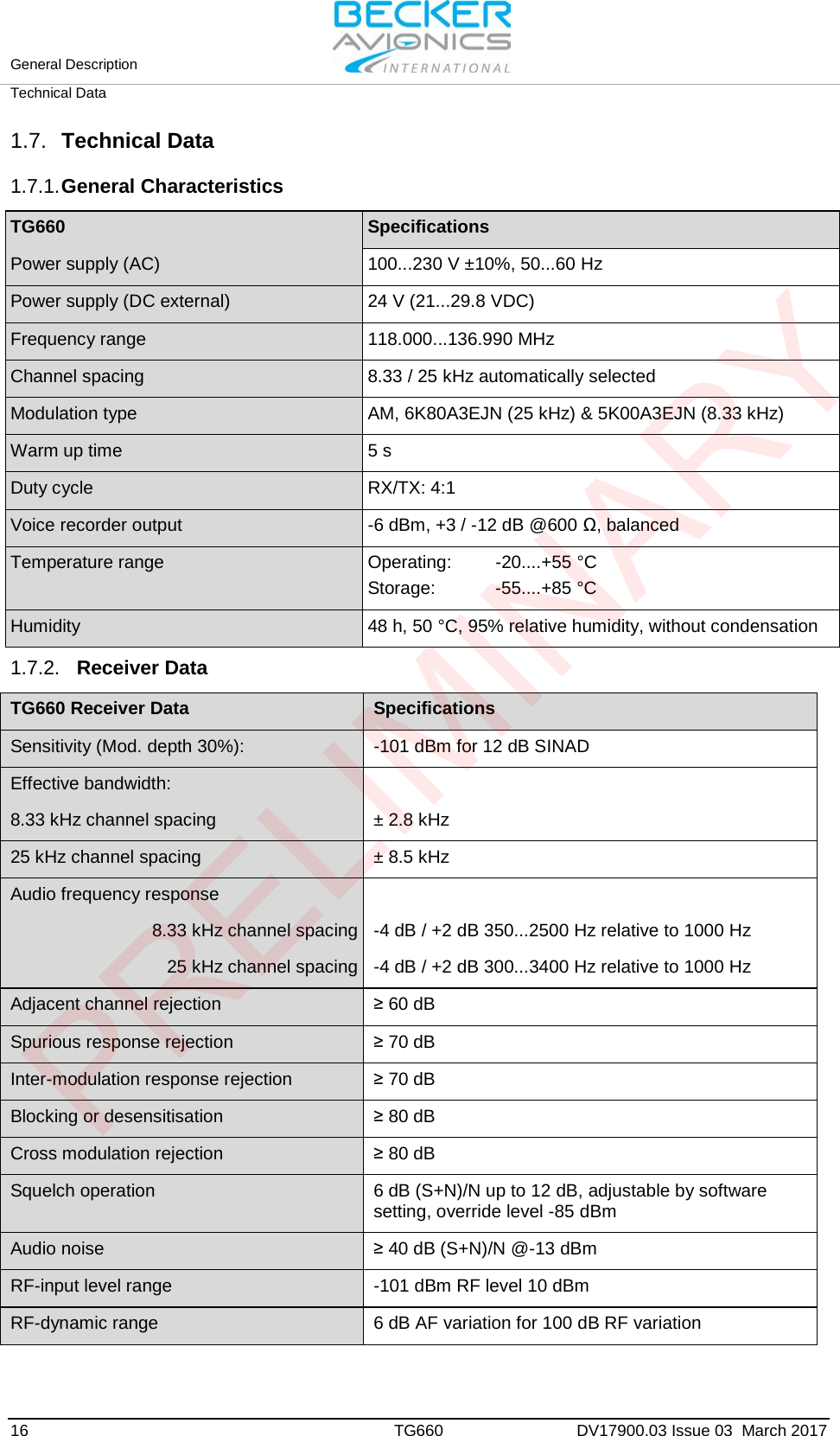
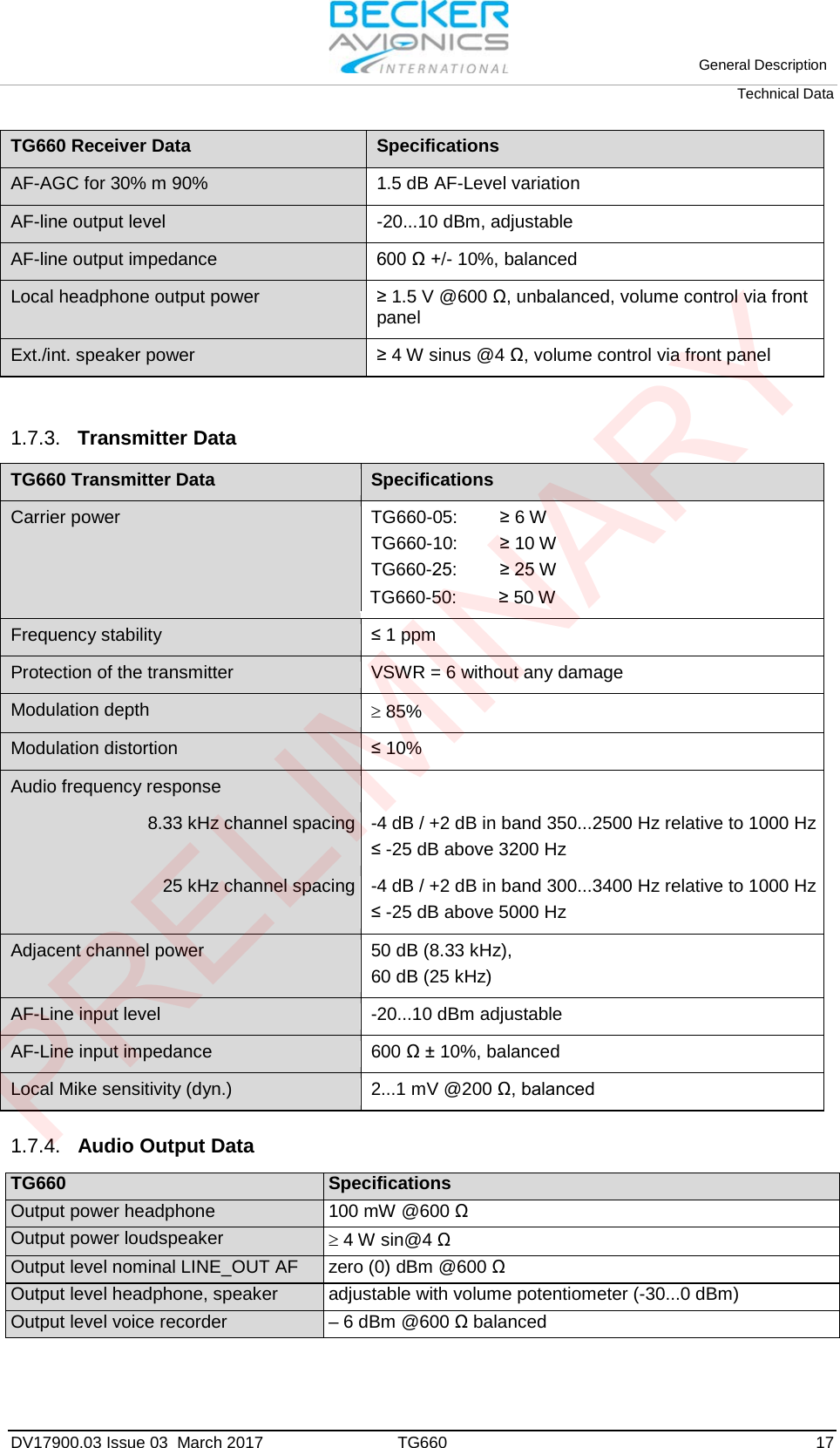
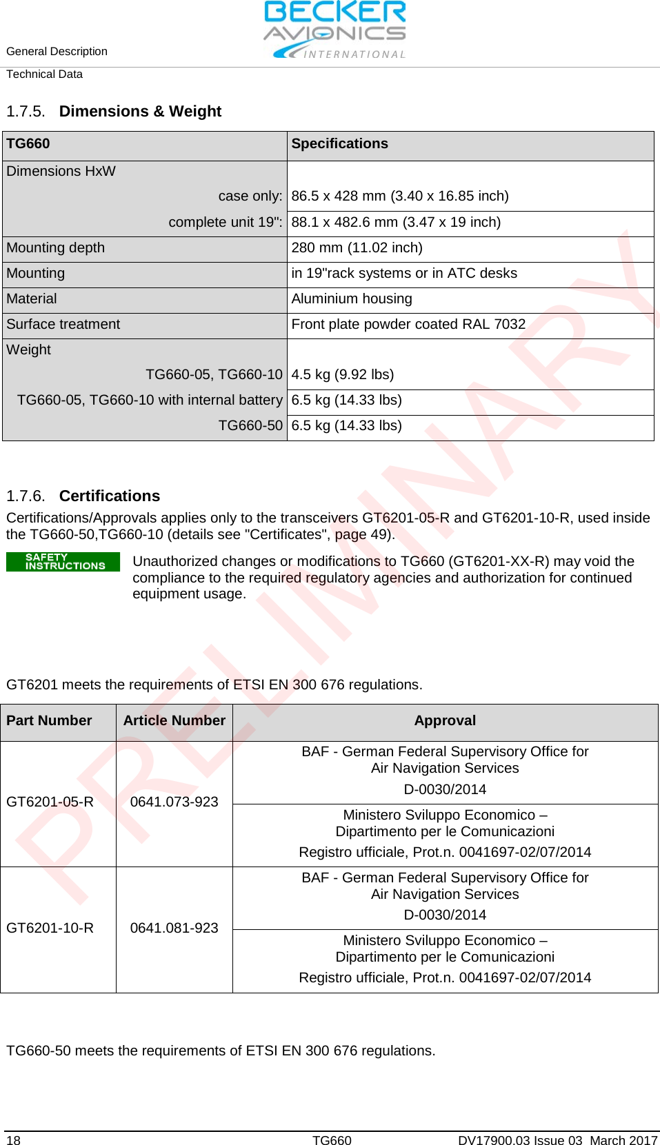
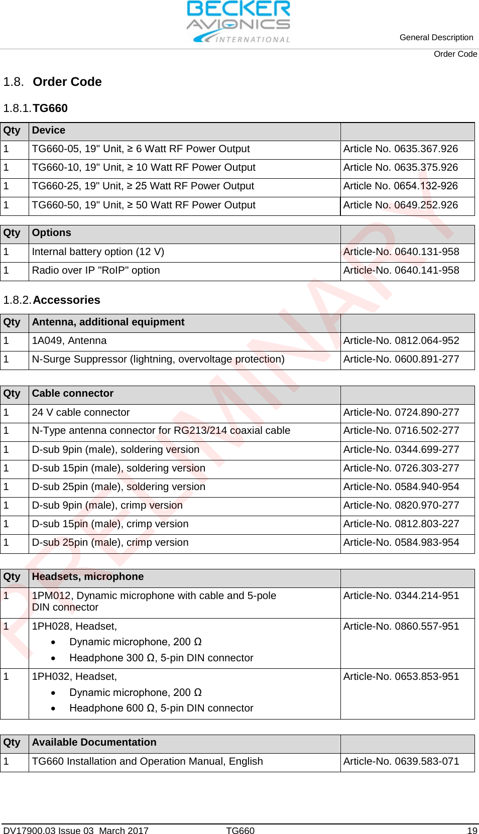
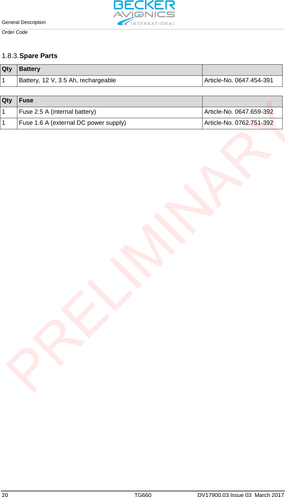
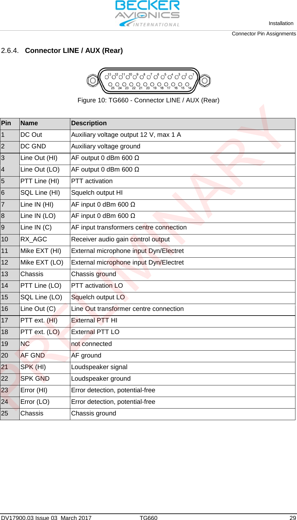
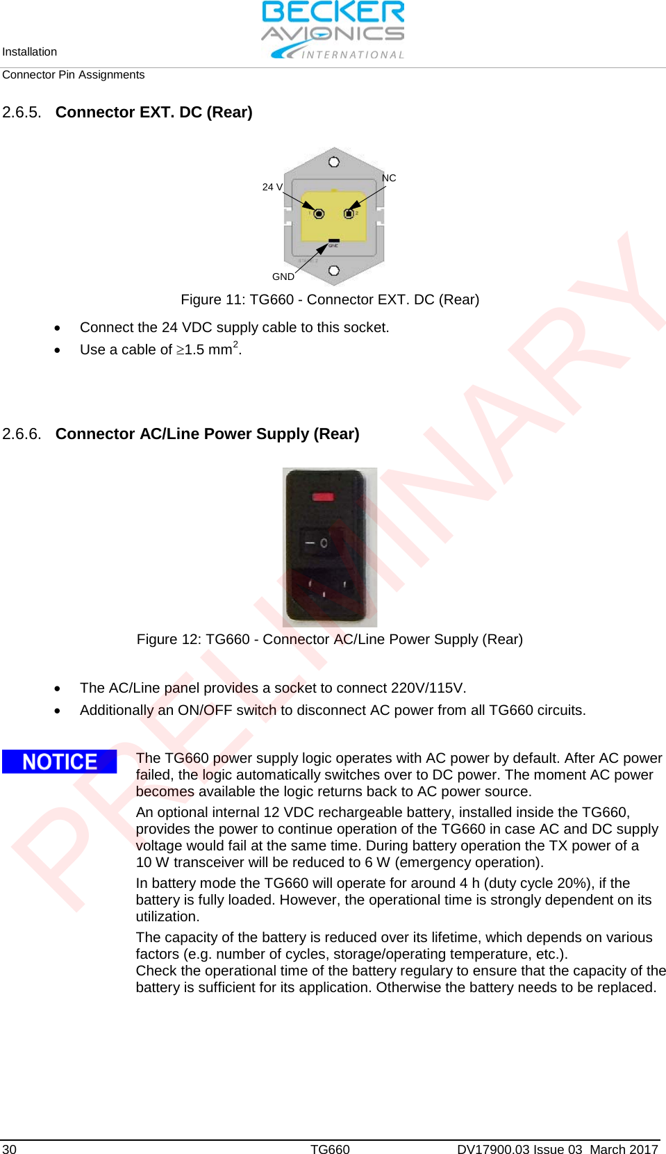
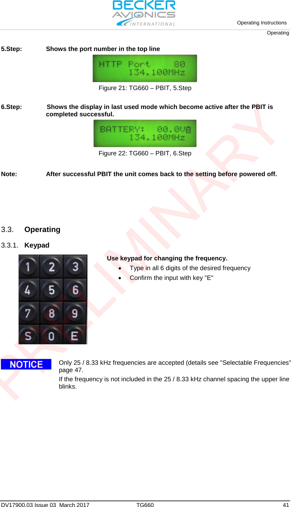
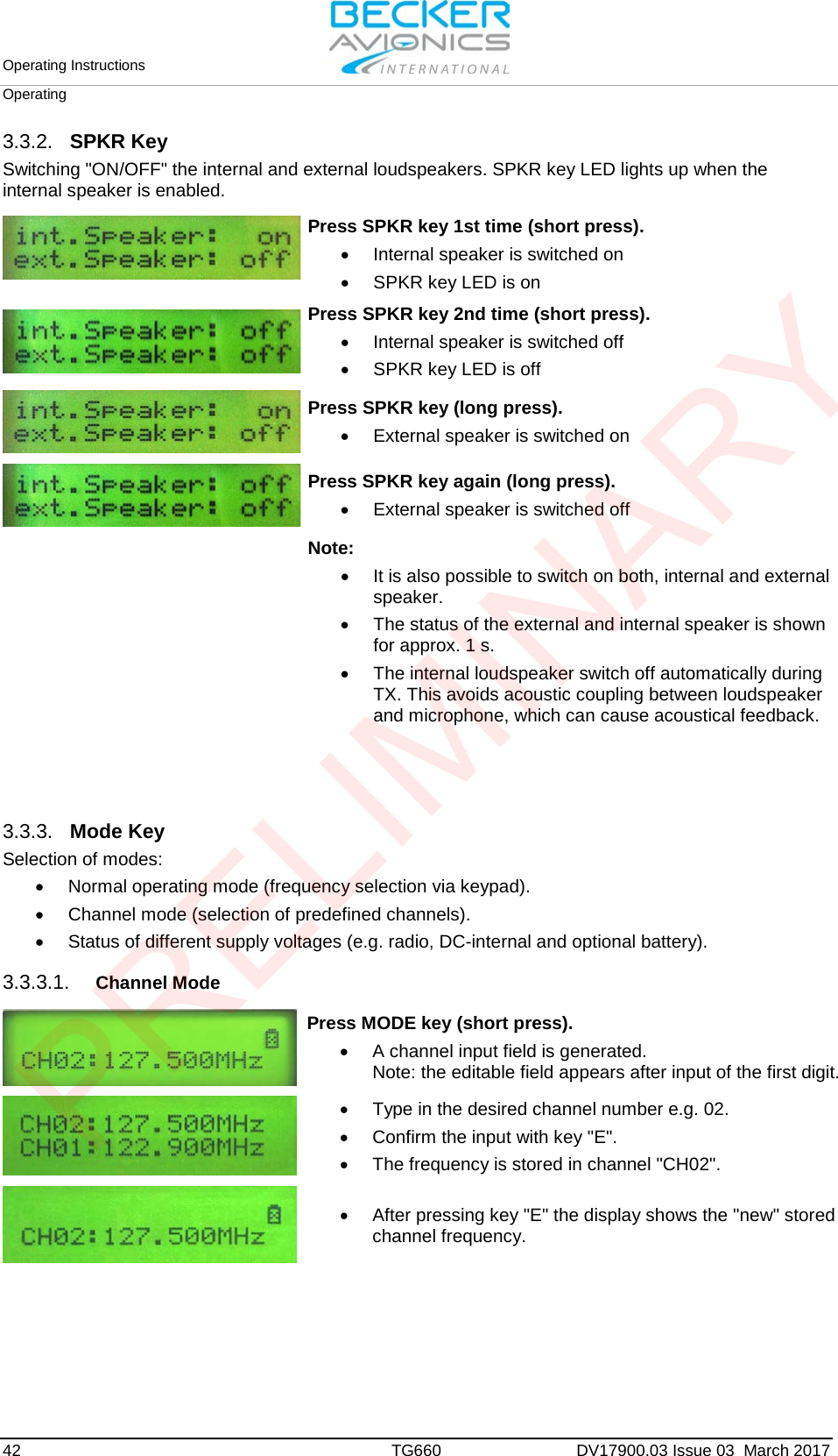
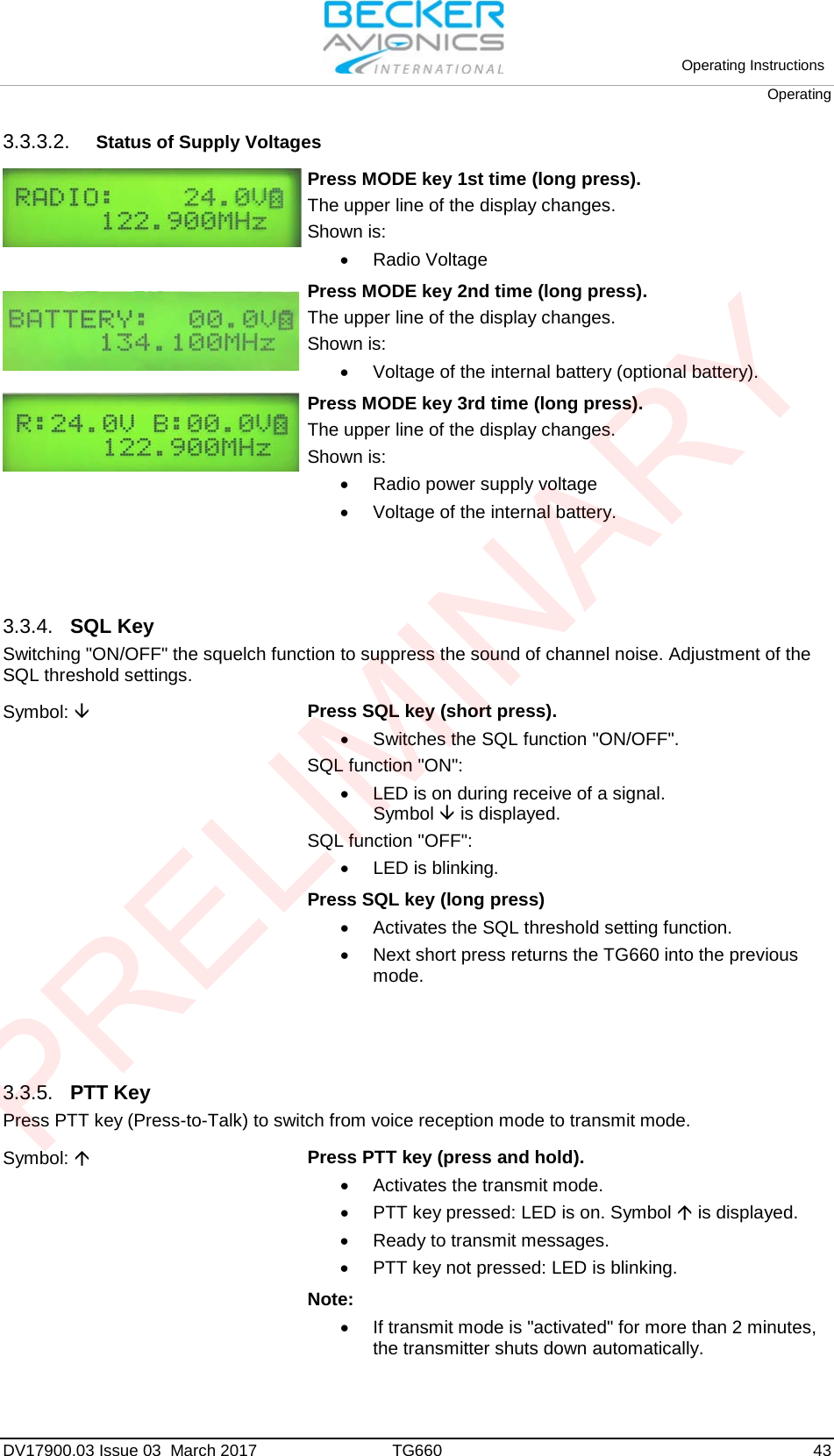
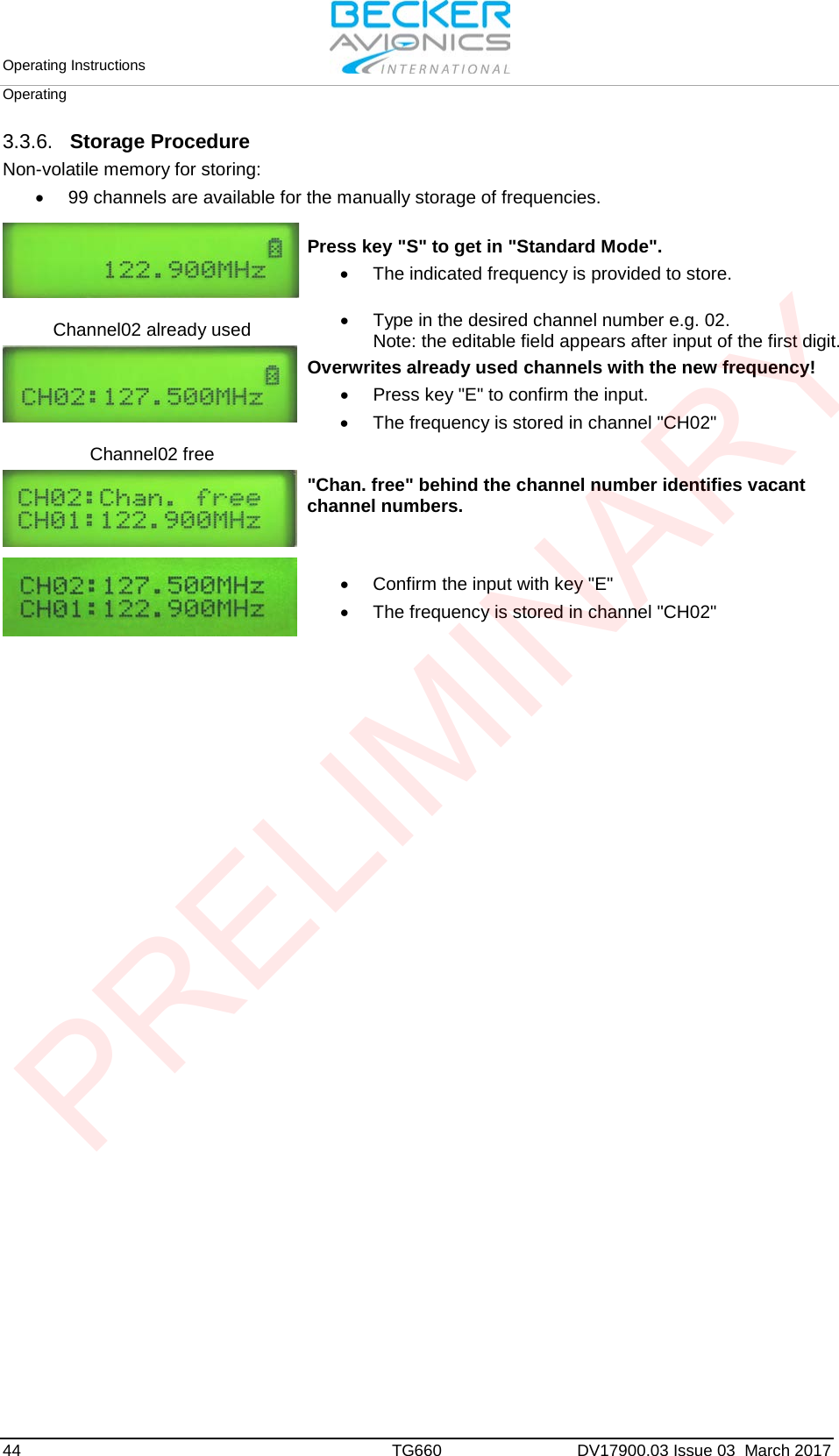
Manual_TG660
4.
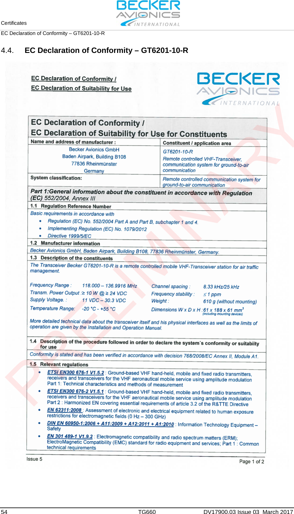
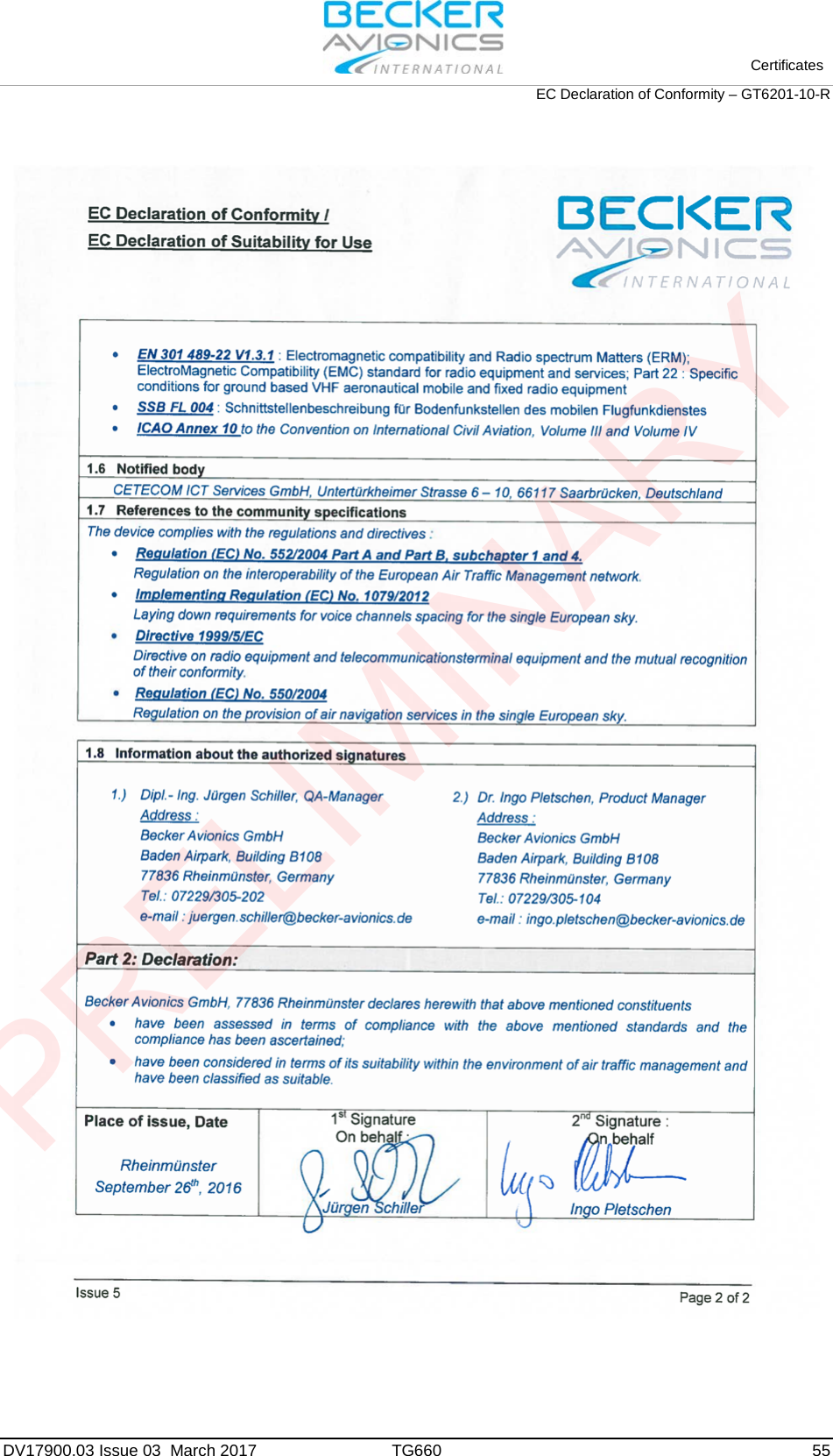
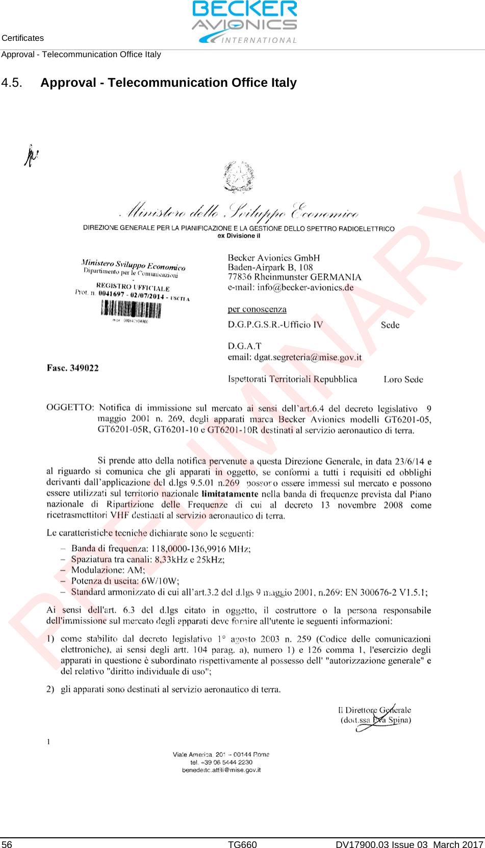
User Manual
5.
Datasheet
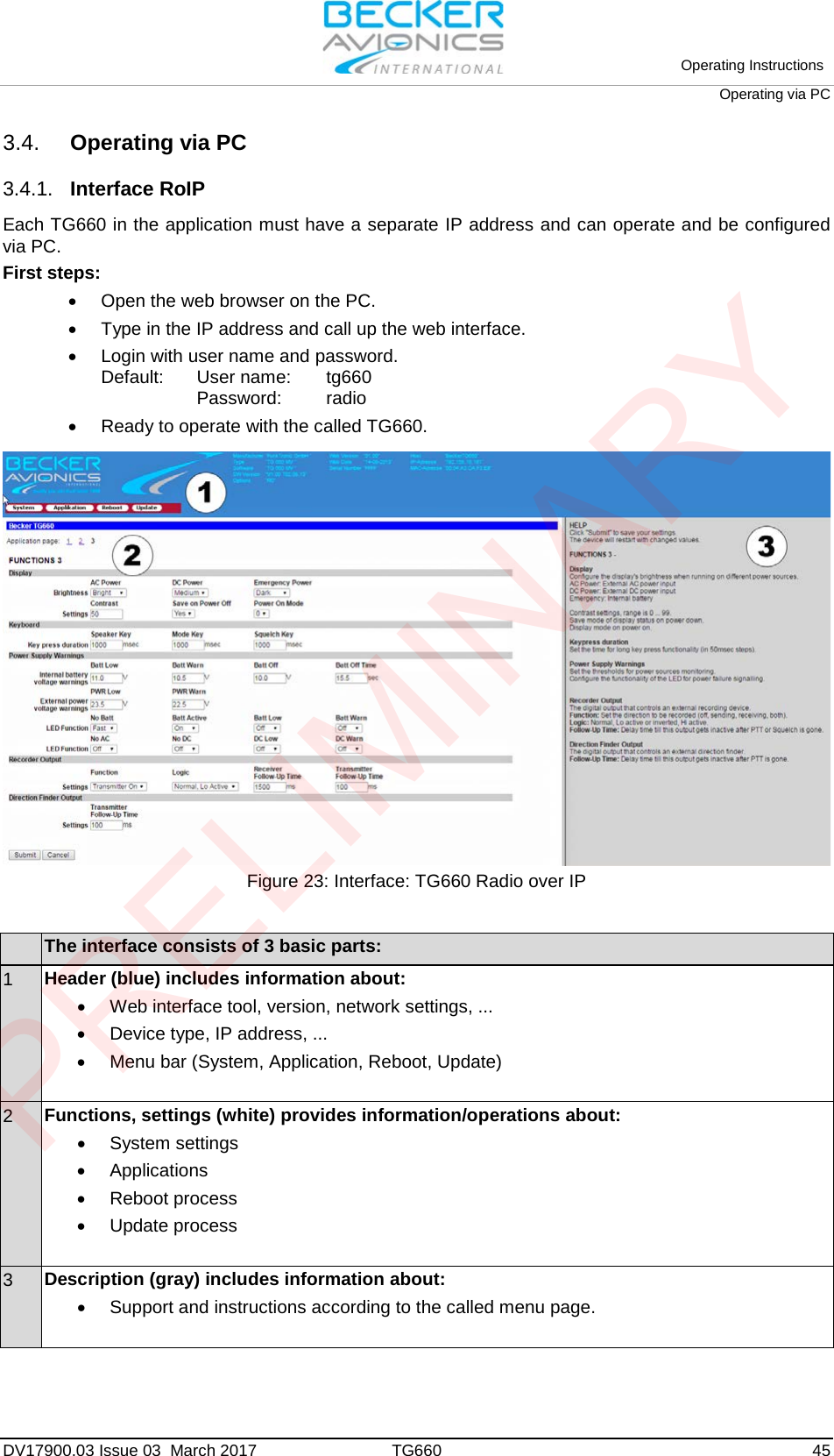
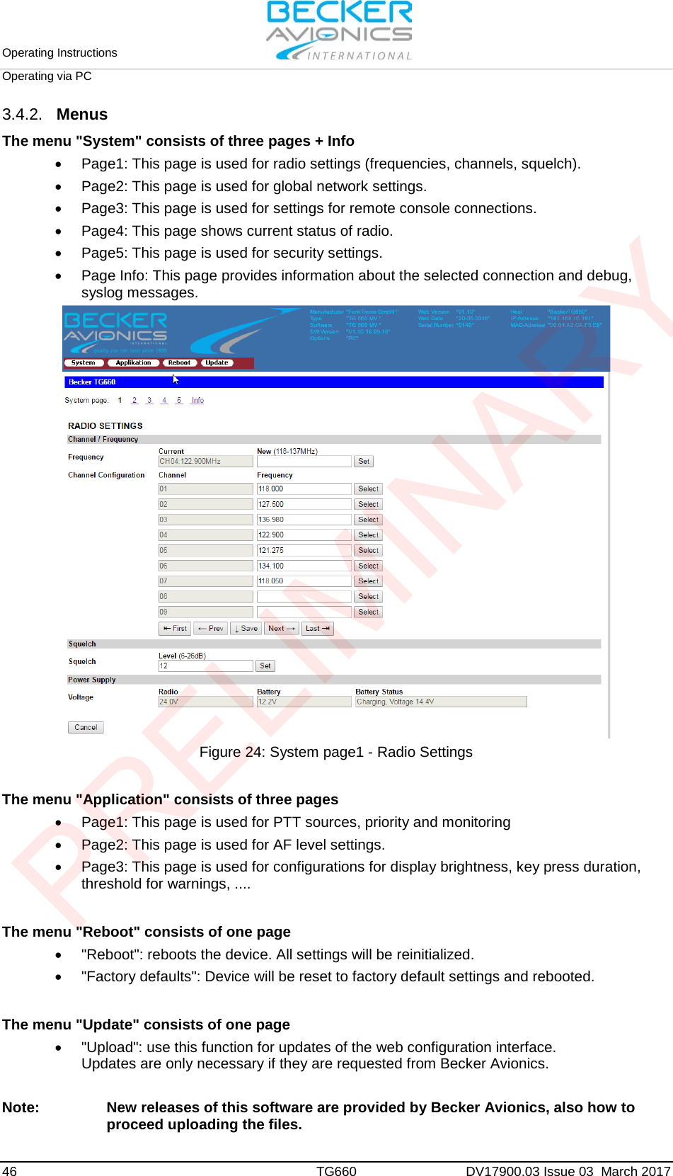
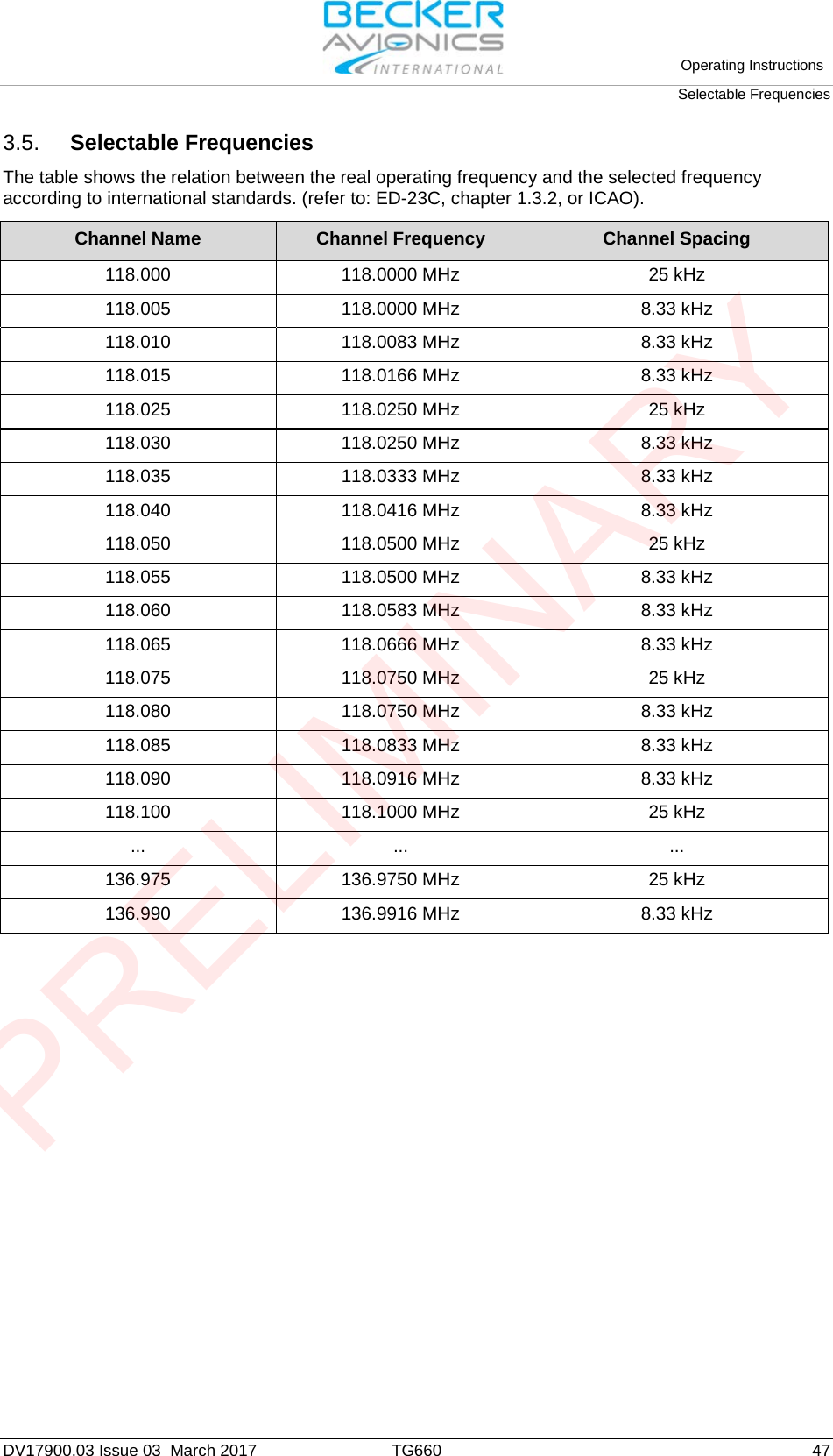
User Manual
Navigation menu
Upload a User Manual
Namespaces
Wiki Guide
HTML
PDF
Info
Views
User Manual
Discussion / Help
Navigation