Cisco Systems 2500-MDM19-C1 2.6 GHz LCD CPE Modem User Manual modem user guide
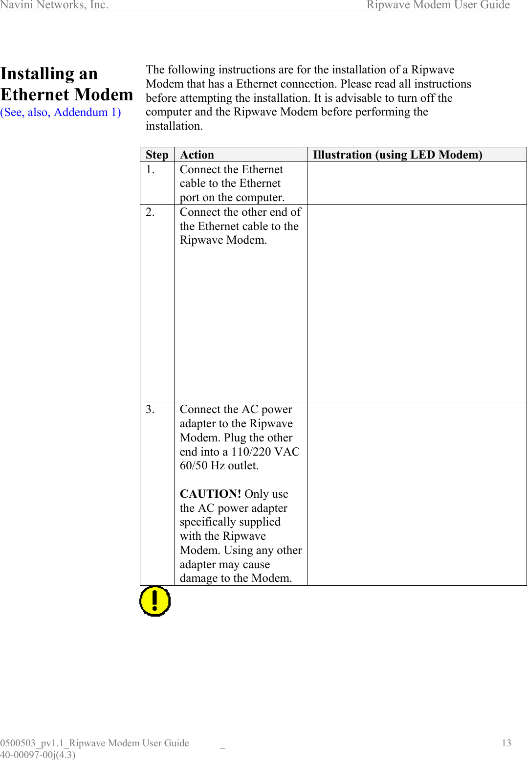
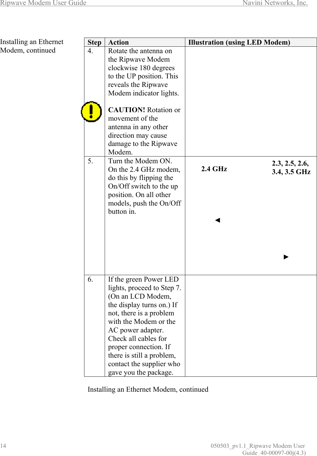
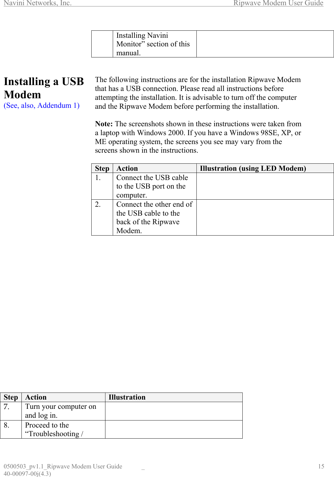
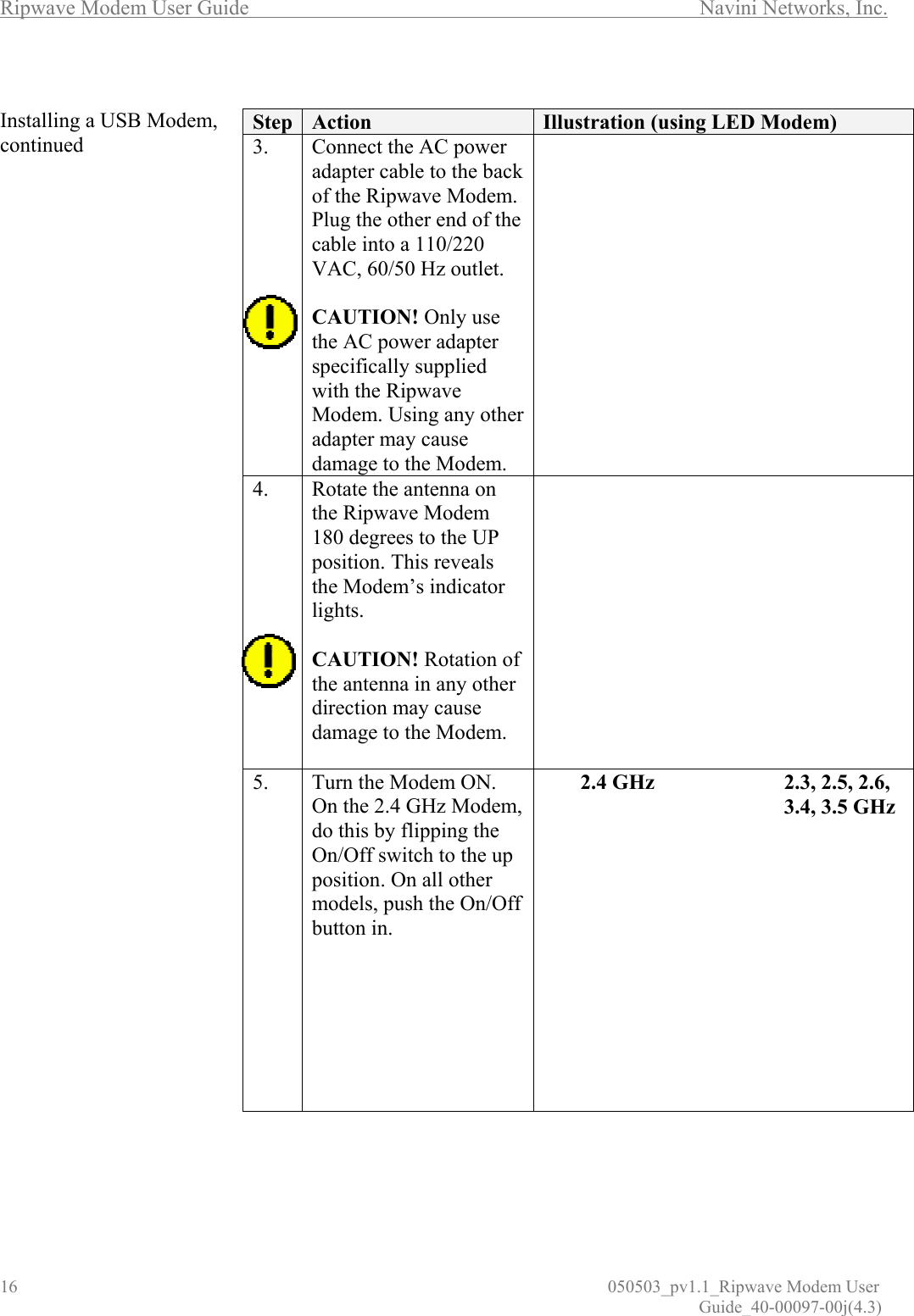
Cisco Systems, Inc 2.6 GHz LCD CPE Modem modem user guide
UserManual.wiki
>
Cisco Systems
>
2500 MDM19 C1 User Manual
User guide
Navigation menu
Upload a User Manual
Namespaces
Wiki Guide
HTML
PDF
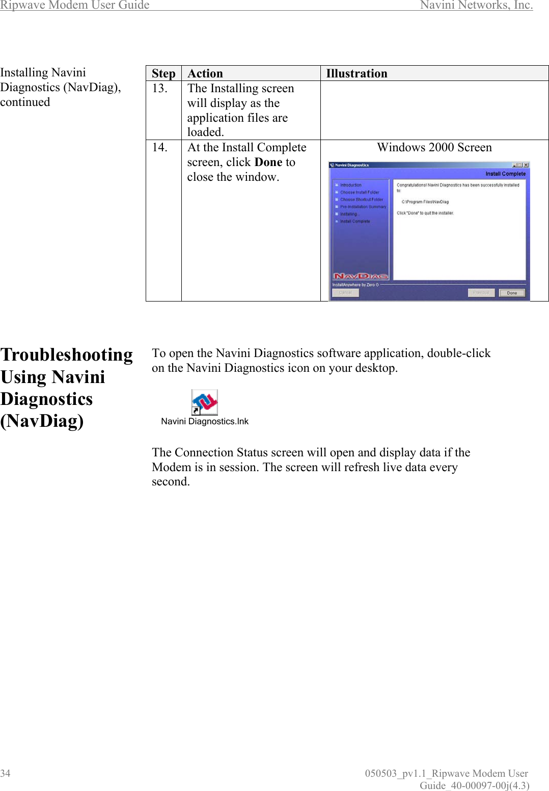
Info
Views
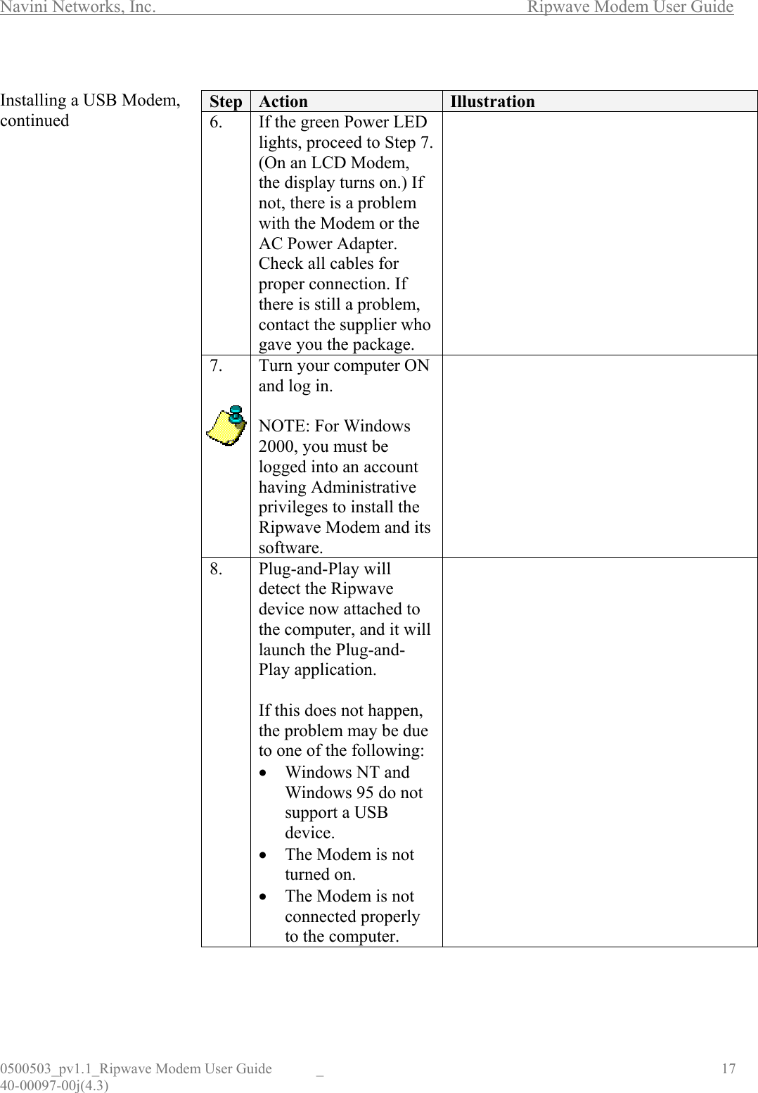
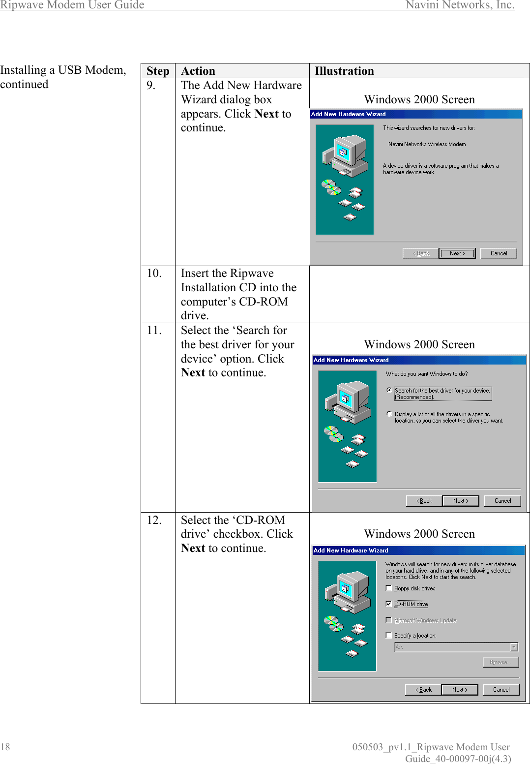
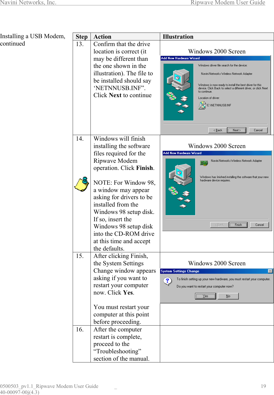
User Manual
Discussion / Help
Navigation