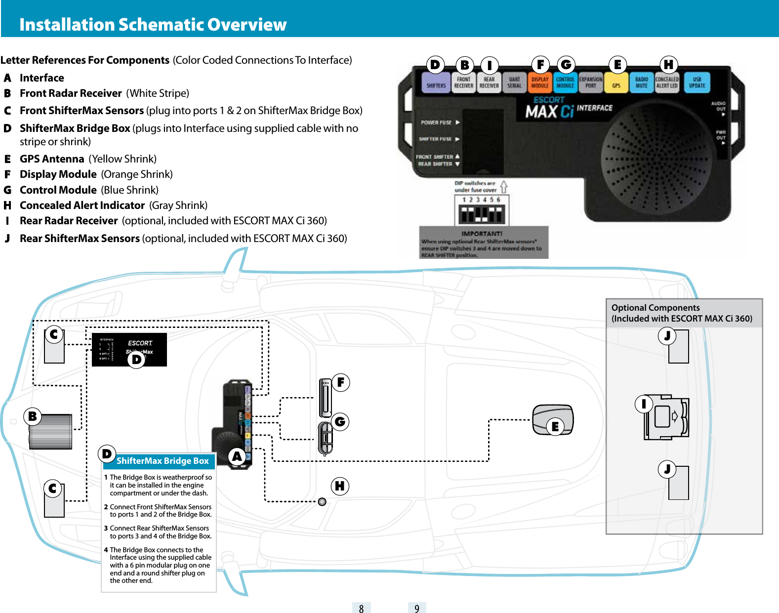
Escort orporated M7R Front Radar Receiver User Manual Installation

Escort Incorporated Front Radar Receiver Installation

Contents

User Manual - Installation.pdf

360°AlertsThe World’s Most Advanced Detection SystemThe most powerful & complete protection availableMAX Ci 360Dual Antenna Front and Rear ProtectionTrue Stealth Operation Lets You Drive 100% Undetected360° Directional Alert ArrowsESCORT Live App Provides Crowd Sourced AlertsGPS  Intelligence Rejects False AlertsLaser Shifters Provide Speed of Light ProtectionInstallation ManualDesigned in the USAESCORT Inc.5440 West Chester RoadWest Chester OH 45069800.433.3487EscortRadar.com©2016 ESCORT, Inc. ESCORT®, Defender®, ESCORT MAX CiTM, ESCORT MAX Ci 360TM, Laser ShifterMaxTM, TrueLockTM, AutoSensitivityTM, SpecDisplayTM, TotalShieldTM, ExpertMeterTM, ESCORT LiveTM, IVT FilterTM and EZ Mag MountTM are trademarks of ESCORT, Inc. FCC NOTE: Modications not expressly approved by the manufacturer could void the user’s FCC granted authority to operate the equipment. FCCID: QKLM7R, FCCID: QKLM3R2, CONTAINS FCCID: QKLBT2This device complies with part 15 of the FCC rules. Operation is subject to the following two conditions: (1) This device may not cause harmful interference, and (2) this device must accept any interference received including interference that may cause undesired operation.
In-dash Display Bezels•  For a factory-installed look, use either the black or    platinum in-dash bezel for easy mounting to    instrument pod, dashboard, or console.•  Integrated adhesive backing for secure mountingControl Module•  Controller mounts easily to instrument pod,    dashboard, or console•  Adhesive pads provided for secure mountingInterface•  Central module connects to switched 12-volt    power and ground•  All components plug directly in using modular   connectionsConcealed Alert Indicator•  Multi-color indicator is: •  Blinking red when receiving an alert • Solid orange when receiving a locked-out alert • Solid green when power is ON • Solid blue when connected to the ESCORT Live      smartphone app•  6-foot cable with modular connector•  Bezel provided mounts easily to instrument pod,    dashboard, or consolRear Laser ShifterMax Sensors* (optional)•  Twin weatherproof sensors•  6-foot cables with waterproof connectors•  4 x 10-foot extension cables•  Mounting hardwareShifterMax Bridge Box•   Weatherproof Bridge Box is used to connect    ShifterMax Sensors to main Interface GPS Antenna•  Weatherproof magnetically mounted GPS   Antenna•  30-foot cable with modular connectorDisplay Module•  Display mounts easily to instrument pod,    dashboard, or console•  Two bezels provided for optional in-dash    mounting•  Adhesive pads provided for secure mounting* Included with ESCORT MAX Ci 360Front Radar Receiver•  Weatherproof radar receiver•  Two universal mounting brackets with stainless    steel hardware•  Built-in 3-foot cable with waterproof   connector•  13-foot cable with waterproof connector and    inline grommet•  12 nylon wire ties to secure cableRear Radar Receiver* (optional)•  Weatherproof radar receiver•  Two universal mounting brackets with stainless    steel hardware•  Built-in 2.9 foot cable with waterproof connector•  13-foot cable with waterproof connector and    inline grommet•  12-foot extension cable with waterproof     connectors•  12 nylon wire ties to secure cableFront Laser ShifterMax Sensors•  Twin weatherproof sensors•  6-foot cables with waterproof connectors•  Mounting hardware and bubble levelESCORT MAX Ci Components2 3Radio Mute Cable•  6-foot cable connects to compatible vehicle    audio systems and automatically mutes the    audio during alertsDownload Data Cable•  Provides access to update data via the InternetDocumentation•  Comprehensive Owner’s Manual•  Installation guideBuilt-in Diagnostics•  Confirms all components are operational
4 5Important Notes Installation Instructions   Installation TipsWhile following the steps throughout this manual, please refer to the following recommendations for a professional, trouble-free installation:1 Determine the best location for the radar receiver. The best location is typically under the bumper, or inside the front grill of the vehicle. For the best radar performance, install the radar receiver horizontally, with a clear “view” of the road.2 Entry points into the interior may be located behind the plastic liner in the wheel  well, fuse box, or unused grommets.3 There are often many existing entry points at the rear of the vehicle as well: • Gaskets behind license plates, around illumination lamps, and near trunk lid hinges. • Tail light wiring gaskets are often easily accessible and large enough to add cables.4 If there are no suitable openings, it will be necessary to drill a hole through the firewall: a. Thoroughly investigate all locations before drilling any holes! Ensure no wires, hoses, or other vehicle components will be damaged. b. On vehicles with automatic transmissions, there is often a location for mounting a clutch pedal. This location is typically an ideal location to drill. c. Before drilling, cover the surface being drilled with masking tape to prevent damage to the anti-corrosion coating in the event the drill bit slips. d. Drill a 13/32" or 7/16" hole.5 When pulling the inline grommet to the entry point, apply rubbing alcohol to a section of the cable to reduce friction and quickly pull the grommet along the length.6 The cables of units mounted at the rear of the vehicle can generally be routed through the trunk compartment and concealed under trim panels quite easily. If necessary, the cables can also be routed under the vehicle and through an opening in the firewall. Be sure to secure cables away from moving parts and hot surfaces.7 A quality crimper for modular connectors can be used to cut cables to length and replace the connector. Removing the connectors may also make it easier to enter the vehicle’s interior through existing openings. Note: • Only an exact replacement for the standard connector can be used. Do not attempt to cut the wires unless the proper connector and crimping tools are available. • Connectors cannot be reused. • Do not cut the cable too short! Provide enough cable to route to the Interface and add a couple extra feet to ease installation • Install the new connector such that its locking tab is on the same side as the color coded stripe on the cable. • Do not attempt to cut the cable and splice the wires together.8 When drilling or cutting interior trim panels (for instance, when installing the Concealed Installation Alert Indicator or the optional Display Bezel), first cover the surface of the panel with masking tape to prevent accidental scratches. E   Read This FirstPlease read these instructions in their entirety before starting your installation.For the easiest, trouble-free installation, install the interface first and wire it to a 12-volt switched circuit.Then, before installing the other components, plug all of them into the interface and power up the unit to confirm proper operation. Installation Warnings1  It is recommended that you have a professional install your new ESCORT MAX Ci . Installation of this system requires experience and expertise in automotive electronics. If you are unfamiliar with automotive electronics, car audio specialists and many car dealers can install your ESCORT MAX Ci  for you.2  Attempting to install this product without expertise in automotive electronics installation can cause personal injury or damage to your vehicle.3  If your vehicle is damaged during installation its safety systems may be compromised, which could cause personal injury or property damage.4  Improper installation may void ESCORT  MAX CI’s warranty. Performance WarningTo get the best performance possible, the mounting location of the radar receiver is critical. Although radar signals will pass through some types of plastic, mounting the radar receiver so that it has a clear “view” of the road will ensure maximum warning.Since Laser signals will not pass through objects, including most plastics, it is critical that the Laser Shifters are mounted perfectly level and have an unobstructed “view” of the road.
6 7   Front Radar Receiver   (Continued)5 Find a suitable entry point into the vehicle’s interior. Refer to the Installation Tips section.6 Feed the harness into the vehicle’s interior and to the Interface. Plug into the connector labeled  “Front Receiver.”7 If entering through a drilled hole, pull the grommet on the harness until the end sticks through the hole. From inside the vehicle, pull grommet through until it seals against the outer surface.  ShifterMax Bridge Box1 The Bridge Box is weatherproof. To limit the number of cables routed through the firewall, we recommend installing the Bridge Box inside of the engine compartment. 2 Slide the included heatshrink onto the Bridge Box Interface cable then plug into the cable extending from the Bridge Box labeled “Interface” and route the cable toward the interior of the vehicle. Shrink the heatshrink onto the inline connector and secure the cable with zip-ties. Although waterproof, it is best to locate the inline connector in a dry area protected from moving parts, road debris, and hot surfaces such as the radiator and radiator hoses.C Front Laser ShifterMax     SensorsPositioning SensorsInstall each sensor halfway between the side and the center of the vehicle.For optimal performance sensors need to be completely unobstructed, not behind a grille, level and facing straight forward (rearward if installing optional rear sensors*). Make sure that each sensor is parallel with the road  (using supplied bubble level).Note: Vehicle must be positioned on a flat surface in order to position sensors parallel with the road. Make sure that sensors have an unobstructed “view” of the road so the unit can function properly. Do not install sensors behind a solid surface, which would block laser transmission/reception.   Interface1 Install the Interface under the dash using supplied zip-ties.Note:Do not mount Interface inside vehicle’s engine compartment!2 Connect black wire (-) to ground, and red-striped wire (+) to a switched 12-volt supply. (If ESCORT MAX Ci is left in the “on” position, it will automatically power on and off with the ignition). 3 Front Radar Receiver, ShifterMax Bridge Box, Display and Control Modules, GPS Antenna, Concealed Alert LED, Radio Mute Cable, and optional Rear Radar Receiver* all plug into the Interface.4 It is recommended that after the Interface is installed and connected to power, all other components are plugged in and tested for proper operation before completing the installation.IMPORTANT!  When using optional Rear ShifterMax sensors* ensure DIP switches 3 and 4 are moved down to the REAR SHIFTER position. See the Interface illustration on pg 9.* included with ESCORT MAX Ci 360   Front Radar Receiver   White Stripe1 Determine the best location for the Radar Receiver. The best location is typically under the bumper or inside the front grille of the vehicle. For the best radar performance install the Radar Receiver flat, horizontally, not on its side.2 Using the supplied U-shaped bracket and the right-angle mounting bracket, mark the mounting location. Drill pilot holes in the vehicle if necessary.3 Mount the Radar Receiver using the supplied hardware. It is recommended that the Radar Receiver is secured to the brackets first, and then the brackets and Receiver mounted to the vehicle.4 Slide the heatshrink onto the Radar Receiver cable then plug into the harness and route the cable toward the interior of the vehicle.  Shrink the heatshrink onto the inline connector and secure the cable with zip-ties. Although waterproof, it is best to locate the inline connector in a dry area protected from moving parts, road debris, and hot surfaces such as the radiator and radiator hoses.A B  D
8 98 9 Installation Schematic OverviewIF G HEBLetter References For Components  (Color Coded Connections To Interface) A Interface B  Front Radar Receiver  (White Stripe) C  Front ShifterMax Sensors (plug into ports 1 & 2 on ShifterMax Bridge Box) D  ShifterMax Bridge Box (plugs into Interface using supplied cable with no        stripe or shrink) E  GPS Antenna  (Yellow Shrink) F  Display Module  (Orange Shrink) G  Control Module  (Blue Shrink) H  Concealed Alert Indicator  (Gray Shrink) I  Rear Radar Receiver  (optional, included with ESCORT MAX Ci 360) J  Rear ShifterMax Sensors (optional, included with ESCORT MAX Ci 360)   DABC DEFGHOptional Components(Included with ESCORT MAX Ci 360)CShifterMax Bridge Box1 The Bridge Box is weatherproof so it can be installed in the engine compartment or under the dash.2 Connect Front ShifterMax Sensors to ports 1 and 2 of the Bridge Box.3 Connect Rear ShifterMax Sensors to ports 3 and 4 of the Bridge Box.4 The Bridge Box connects to the Interface using the supplied cable with a 6 pin modular plug on one end and a round shifter plug on the other end.D J JI
   GPS Antenna  Yellow Shrink1 Determine the best location for the GPS antenna. The GPS Antenna requires a clear view of the sky. The magnetic base can be used on most vehicles to mount to the roof of the car or the trunk lid. It can also be mounted to the dashboard or rear deck using double-sided tape.2 Mount the GPS Antenna, being sure that roof racks or other obstructions do not block its view of the GPS satellites.3 Locate a suitable entry point into the vehicle. Refer to the Installation Tips section for locating a suitable entry point.4 Route the cable through the entry point and secure along its path. If mounting near the front or rear window, it is usually possible to tuck the cable under the gasket surrounding the glass.5 Once inside the vehicle’s interior, route the cable to the Interface and plug into the connector  labeled “GPS.”6 Secure and conceal the cable under interior trim panels.               Display Bezel Mounting1 The supplied display bezel can be used to mount the Display permanently in the dash or console.2 Determine the best location for the Display Module. If installed by a professional, the customer should be consulted. A flat, plastic surface with no obstructions behind it is best for this type of mounting. 3 Cover the mounting surface with masking tape to prevent accidental scratches. 4 Using the supplied hole template, mark the location. 5 Ensure there are no hidden cables, brackets, or other components behind the location, and that there is adequate clearance behind the panel. The Display will protrude into the dash or console by 1/2". 6 Very carefully cut the hole in the mounting surface. 7 Feed the display module cable through the bezel and the opening in the dash then route it to the interface. 8 Remove the masking tape protecting the trim panel. 9 Clean the mounting surface thoroughly. 10 Apply the double-sided adhesive tape to the display bezel. 11 Mount the Display Module using the bezel adhesive. 12 Plug the connector into the Interface connector labeled “Display Module.” 13 Secure and conceal the cable under trim panels.10 11E Front Laser ShifterMax     Sensors (Continued)1 Snap mounting bracket onto sensor and install the included bolts but do not tighten them. If the bolts do not thread into the sensor then you have the bracket on backwards.2 Apply the double sided tape to the underside of the sensor’s mounting bracket. Check front alignment and mount the sensor to a solid surface of the vehicle. 3 Use the supplied bubble level to ensure the sensor is parallel to the road and tighten the sensor’s mounting bracket bolts.4 Repeat for additional sensor(s).Securing Connectors with Shrink TubeOnce you’ve installed all components properly and tested to ensure all parts are working properly, use cable ties to fasten sensor cables to a solid surface, keeping them away from heat and any moving parts. It is advisable to use the supplied heatshrink tubes to protect connectors against water, moisture, dust, etc.IMPORTANTLY the ShifterMax sensors are shipped in “receive only” mode. Shifting must be enabled in the bands settings. See the Preferences section of the Owner’s Manual.Additional ShifterMax Sensors•  ESCORT MAX CI users wanting to add rear sensors, two (2) additional ShifterMax Sensors with included hardware are sold separately.   Display Module  Orange Shrink1 Determine the best location for the Display Module. If installed by a professional, the customer should be consulted. An optimal location is clearly visible from the driver’s position and does not take a driver’s eyes off the road for more than a moment.2 Clean the mounting surface thoroughly. 3 Mount the Display using the pre-applied adhesive.4 Route the cable to the Interface and plug into the connector labeled “Display Module.” 5 Secure and conceal the cable under trim panels.F
   Control Module  Blue Shrink1 Determine the best location for the Control Module. If installed by a professional, the customer should be consulted. An optimal location is easily visible and accessible from the driver’s position, and does not interfere with normal driving. Avoid locations that require reaching through or around the steering wheel.2 Clean the mounting surface thoroughly.3 Mount the Control using the pre-applied adhesive.4 Route the cable to the Interface and plug into the connector labeled “Control Module.”5 Secure and conceal the cable under trim panels.                Concealed Alert       Indicator  Gray Shrink1 Determine the best location for the Alert Indicator. If installed by a professional, the customer should be consulted. An optimal location is clearly visible from the driver’s position and does not take a driver’s eyes off the road for more than a moment.2 Ensure there are no hidden cables, brackets, or other components behind the mounting location, and that there is adequate clearance behind the panel.3 Cover the mounting surface with masking tape to prevent accidental scratches.4 Carefully mark the location and drill a 1/4" hole through the mounting panel.5 Remove the masking tape protecting the trim panel.6 From the front side, snap one of the panel bezels provided into the hole.7 Snap the Alert Indicator into the panel bezel from the back side.8 Route the cable to the Interface and plug into the connector labeled “Concealed Alert LED.”9 Secure and conceal the cable under trim panels.   USB Update CableThe USB Update cable allows updating the ESCORT MAX Ci’s DEFENDER database and firmware. ESCORT MAX Ci’s red light and speed camera DEFENDER database is easily updated using our exclusive detector software tools found on our web site. Firmware, or the operating software for the detector, can also be updated using these tools.In order to have access to these updates, please register your ESCORT MAX Ci at www.EscortRadar.com. Once registered, you will receive email notifications when updates are available.12 13GH      Rear Radar Receiver* optional1 Follow the same installation instructions as for the Front Radar Receiver but with the receiver’s arrow oriented to point out the rear of the vehcle.2 Entry points to the vehicle’s interior may be available behind the license plate or lights.I      Rear Laser ShifterMax                    Sensors* optionalIMPORTANT!  When using optional Rear ShifterMax sensors* ensure DIP switches 3 and 4 are moved down to the REAR SHIFTER position. See the Interface illustration on pg 9.1 Follow the same installation instructions as for the Front Laser ShifterMax Sensors but with the sensors oriented to point out the rear of the vehicle.2 Entry points to the vehicle’s interior may be available behind the license plate or lights.   Radio Mute Cable1 The radio mute cable (included) allows the detector to be connected to compatible audio systems with a “Radio Mute” wire or connector. Once connected, the audio level of the stereo is reduced automatically during an alert.2 Please refer to your audio system’s manual for proper connection to your audio system.J   Operation TestAfter all components are installed correctly:1 Turn ESCORT MAX Ci on by turning on the vehicle’s ignition and, if necessary, press the power button on the Control Module.2 ESCORT MAX Ci will cycle through a startup sequence.3 If any error messages come up, see the Owner’s Manual troubleshooting section for suggested solutions. * included with ESCORT MAX Ci 360If you have any questions, please call or visit our website. One of trained radar specialists will be happy to assist you.   800-543-1608  /  EscortRadar.com

Navigation menu