Faro Technologies 14000 PORTABLE LASER LINE MEASUREMENT ARM User Manual FARO EDGE Laser ScanArm Users Manual
Faro Technologies, Inc. PORTABLE LASER LINE MEASUREMENT ARM FARO EDGE Laser ScanArm Users Manual
Contents
- 1. Users Manual 1
- 2. Users Manual 2
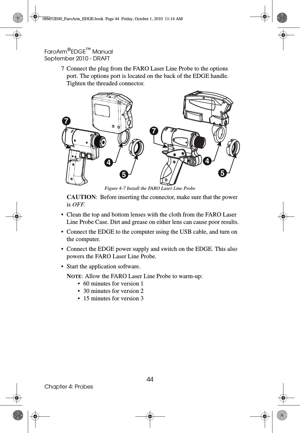
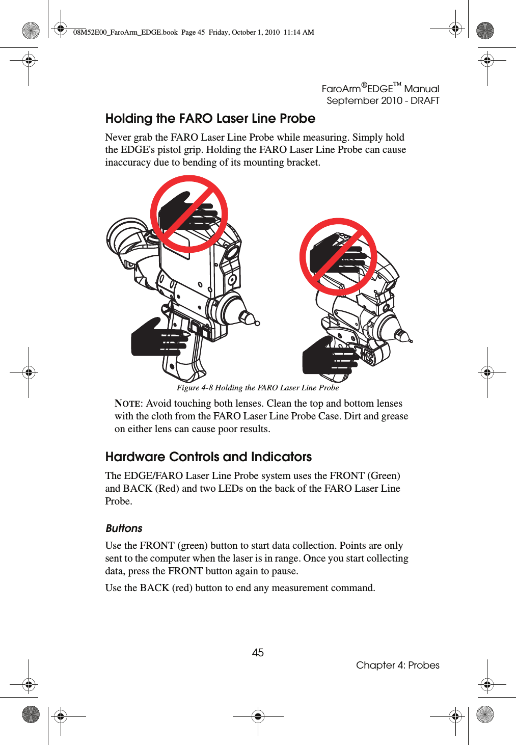
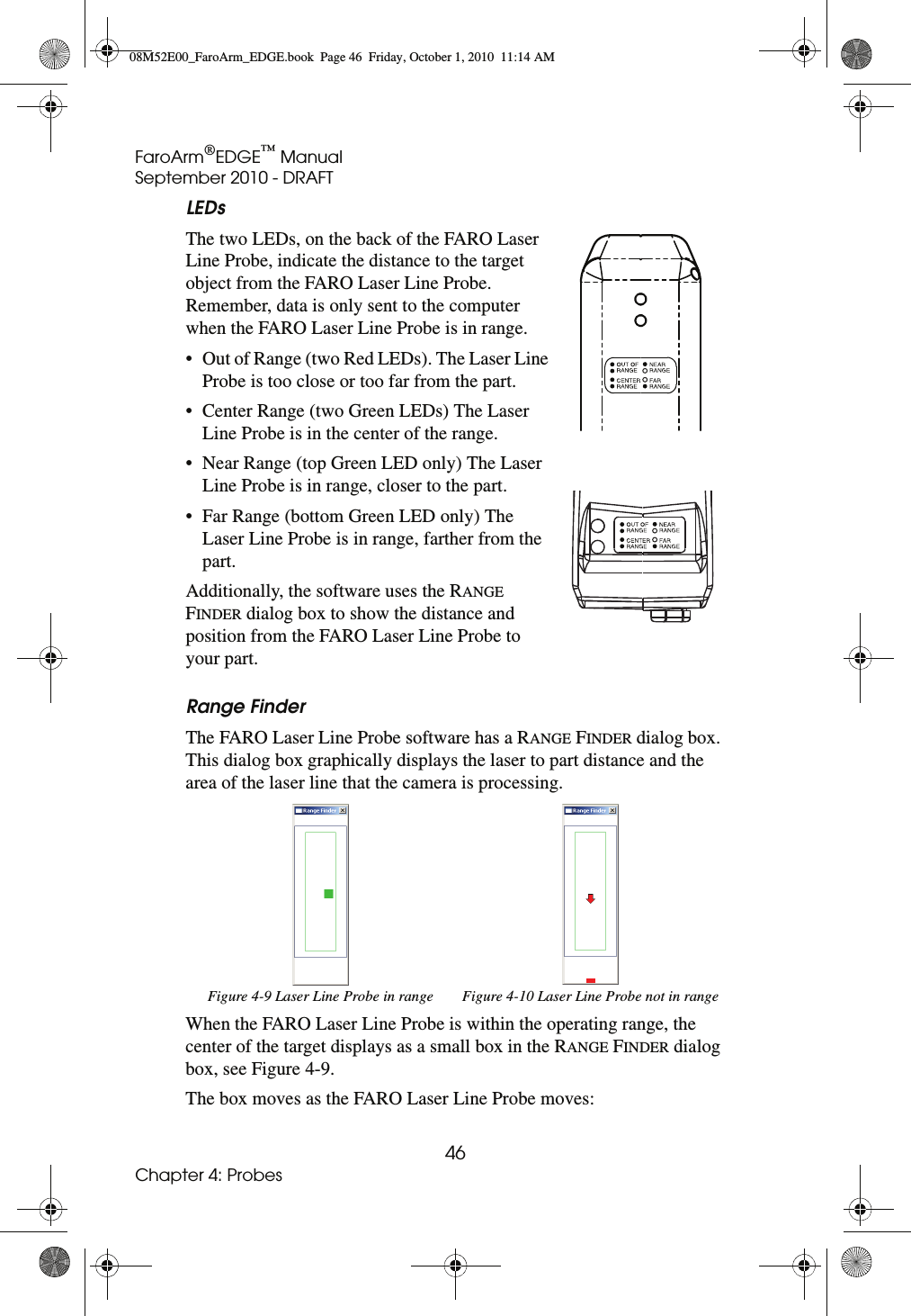
Users Manual 1