Future Systems FGT100 VPN GATEWAY User Manual FCC040401
Future Systems, Inc. VPN GATEWAY FCC040401
Contents
- 1. Users Manual 1
- 2. Users Manual 2
Users Manual 1


SecuwayGate 100(Model : FGT100)
Install/Administrator Guide


SecuwayGate 100 Install/Admistrator Guide
Copyright Future Systems, INC., All rights Reserved.
ⓒ
Future Systems, Inc. owns the copyright of this manual. No part
of this manual may be reproduced or transmitted in any form or
by any means, electronic or mechanical, without the consent of
Future Systems, Inc. The information in this document is subject
to change without notice.
SecuwaySuite 2000
SecuwayCenter 2000
SecuwayGate 2000
SecuwayGate 6000
SecuwayGate 1000
SecuwayGate 100
RenoGate
SecuwayClient 2000
These are registered trademark of Future Systems, Inc.
All other product names or company names mentioned herein
might be property of their respective companies.

iii
Future Security Solutions
Future Systems, Inc. is an Internet/network security solution
specialized company and provides total security solution service
such as network security equipment, security software, and security
consulting Future Systems, Inc. provides the following Security
systems.
SecuwaySuite 2000 consists of SecuwayCenter 2000,
SecuwayGate 2000, SecuwayGate 6000, Secuway
Gate 1000, SecuwayGate 100, RenoGate and
SecuwayClient 2000, which are interlinked with each other to
provide VPN and firewall features. SecuwaySuite 2000 is
designed to have a low possibility that a source of threat with a
medium level of expert knowledge, resources and motivation will
discover vulnerabilities that can be abused, and a medium degree of
security strength against attackers with a medium level of expert
knowledge, resources and motivation. The following is a brief
description of each product
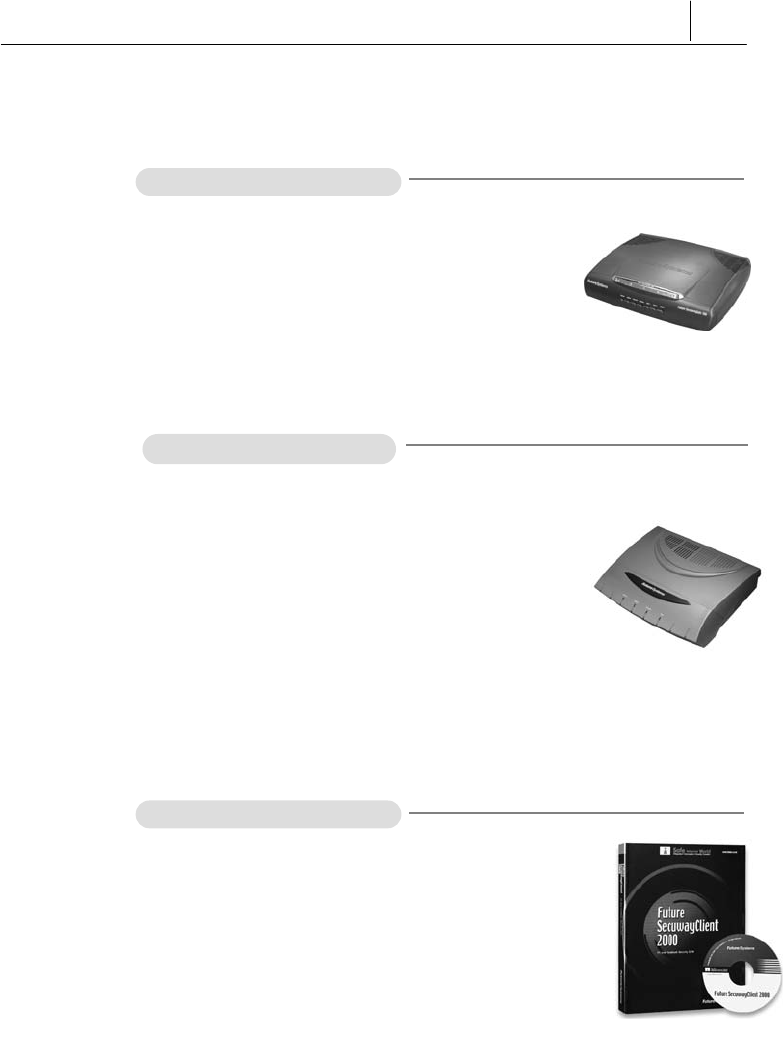
SecuwayCenter 2000
SecuwayCenter 2000 is a total security
management system that sends the security
information via online and supports real time
management working together with Secu
wayGate 2000, SecuwayGate 6000,
SecuwayGate 1000, SecuwayGate
100, RenoGate, SecuwayClient
2000.

iv
SecuwayGate 2000
SecuwayGate 2000 is a hardware based
security system that integrates security key
solutions like VPN, Firewall, and intrusion
detection system to minimize the overload of
network speed due to adding the security
system.
SecuwayGate 6000
SecuwayGate 6000 is a specialized
hardware-based security system facilitated
with the integrated features of VPN, firewall,
and network intrusion detection.
SecuwayGate 6000 is a high-speed,
high-capacity device specially designed for a
large enterprise network in order to minimize
the deterioration of network performance
caused by the overload of the integrated
security features.
SecuwayGate 1000
SecuwayGate 1000 is a hardware based
security system that integrates security key
solutions like VPN, Firewall, and intrusion
detection system to minimize the overload of
network speed due to adding the security
system.
v
SecuwayGate 100
SecuwayGate 100 is a hardware based
security system that integrates security key
solutions like VPN, Firewall, and intrusion
detection system to minimize the overload of
network speed due to adding the security
system.
RenoGate
RenoGate is a specialized hardware-based
security system facilitated with the integrated
features of VPN, firewall, and network intrusion
detection. RenoGate is specially designed for
a small enterprise network to provide optimal
security and network management features
while minimizing the deterioration of network
performance caused by the overload of the
integrated security features.
SecuwayClient 2000
SecuwayClient 2000 is security software
that provides the system security and network
communication security for Desktop PC and
Note PC.

vi
User Requirements and Cautions
Administrators who are authorized to use SecuwayGate 100
must have no malicious intention. To be a qualified
SecuwayGate 100 administrator, you must have been trained
to understand the administrative features of SecuwayGate 100
and to perform various administrative tasks according to the
instructions provided in this guide. Such administrative skills
fundamentally require solid background knowledge and related
experiences in secure networking environment, including computer,
network terminology, security and general software installation
procedures. If you are not familiar with using computers and/or
security systems, please consult the Future Systems, Inc. or other
experts about the installation and operation of SecuwayGate
100.
z
Password Security
A SecuwayGate 100 administrator must change all of the
passwords set in SecuwayGate 100 at least every 12 month. Any
personal information related to the administrator must not be
included in the password. Passwords must not be shared with others
or written down anywhere.
z
Access to this Document
It is strongly recommended to provide limited access to this guide,
only to those who are authorized to manage network security or
perform security related tasks. Special attention needs to be paid in
the management of this document to prevent a user with malicious
intention from misusing this document to acquire information for
intruding the network and system resources.
z
Physical Security
SecuwayGate 100 must be installed in a physically secure
environment, to where only authorized network security support
staff has access. When selecting and maintaining such environment,
the overall network stability, system stability against outside

vii
intruders, and physical safety from external environmental factors
must be considered
z
Maintain Security Policy
Whenever there is a change in the existing network environment (e.
g. a modification of the network configuration, an increase or
decrease of new hosts, etc.), you need to reflect the change
immediately to the existing security policies of SecuwayGate
100 to keep the equivalent level of security policy.
z
Single Connection Point for Secure Communication
All communication between the internal network and the external
network must be controlled by SecuwayGate 100. Otherwise,
the effect of the key security features such as VPN, firewall, and IDS,
cannot be guaranteed.
z
Check the Validity of Certificate
The digital certificate of the SecuwayGate 100 must be issued
by SecuwayCenter 2000 or by the Certificate Authority. Be
sure to check the validity of all keys and digital certificates before
you use them.
z
Operation Modes -
SecuwayGate 100
SecuwayGate 100 can be operated in Initial, Normal,
Administrator, or Error mode. Initial mode refers to the state in
which the SecuwayGate 100 administrator has initialized
SecuwayGate 100 using the smart card or file issued from
SecuwayCenter 2000. Normal mode refers to the state in
which all the functions are working properly after a set of security
policies as been received from the SecuwayCenter 2000.
Administrator mode is used to backup the audit log file or to stop
and restart SecuwayGate 100 during the normal operation
mode. Error mode refers to the state in which SecuwayGate
100 is not working properly, due to a program error or other
problems.
viii
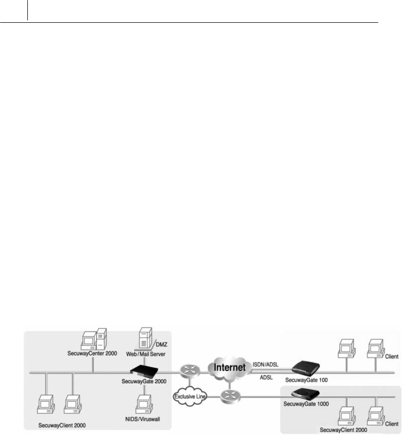
SecuwaySuite 2000
Configuration
Example
SecuwaySuite 2000 configures SecuwayCenter 2000
SecuwayGate 2000/6000/1000/100, RenoGate,
SecuwayClient 2000 like the following to provide the various
security solutions.
z Intranet Server security
z Server access control by each Client and User authentication.
z Protect the intra network from extra network using intrusion
detection.
z Provides the security for Mobile user and SOHO user.

ix
Before You Begin
This Guide describes how to operate and manage the
SecuwayGate 100 system. The following explains what you
need to know about reading this guide.
Who Should Read This Guide
This user guide is intended for users who have a fundamental
understanding of computers, network terminology, security and
general software installation procedures. If users are not familiar
with computers, or security systems, please consult the Future
Systems, Inc. or other experts about the installation and operation of
this system.
About This Guide
This guide includes the overview, operation, and management of
SecuwayGate 100. It has been organized according to the order
of the job sequences so that you can also easily find and read only
the most relevant section.
To install and operate SecuwayGate 100, users should refer to
this guide, even if users are familiar with other security system
similar to SecuwayGate 100.
Should you encounter any problems using SecuwayGate 100, consult
your product distributor and let an expert help you.
If you encounter any problems or the product is damaged, please contact
your product distributor.

x
Conventions Used In This User Guide
This user guide uses the following conventions to present
information.
Caution and Note
Caution and note marks in this guide have the following meanings
respectively:
A Caution indicates that failure to follow the directions could result in damage
to the SecuwayGate 100 system or cause the malfunction of
SecuwayGate 100.
A Note provides helpful tips on easy use of various functions for the
SecuwayGate 100 system.

xi
Contents of Administrator Guide
This guide consists of 6 chapters. Basically this guide is organized
according to the order of each job sequence from a general summary
to the actual use of the program. You may choose and read any
appropriate sections first.
To use the SecuwayGate 100 system properly, sequential
reading of this guide is recommended. However, for users who only
want to read individual sections, each chapter is summarized as
follows.
Chapter 1 SecuwayGate 100 Overview introduces the features and
the specifications of SecuwayGate 100, and describes LED’s
and ports on the front and the rear side of the system.
Chapter 2 SecuwayGate 100 Installing describes procedures to
install SecuwayGate 100.
Chapter 3 SecuwayGate 100 Connection Examples describes by
examples how to connect SecuwayGate 100 to provide
various security functions.
Chapter 4 Operating SecuwayGate 100 describes procedures to
operate SecuwayGate 100.
Chapter 5 Console Commands describes console commands that can
be used when connecting to the console port of SecuwayGate
100 or when configuring SecuwayGate 100 to allow telnet
connection.
Chapter 6 Upgrading Firmware describes how to upgrade the
firmware of SecuwayGate 100.
Appendix Q&A About SecuwayGate 100 answers the frequently
asked questions about the problems encountered while operating
SecuwayGate 100.

xii
Contents
SecuwayGate 100...............................................................................................................1
Administrator Guide.............................................................................................................1
Future Security Solutions ......................................................................................................................iii
User Requirements and Cautions.......................................................................................................vi
SecuwaySuite 2000
Configuration Example
..................................................................... viii
Before You Begin.......................................................................................................................................ix
Who Should Read This Guide .........................................................................................................................ix
About This Guide .................................................................................................................................................ix
Conventions Used In This User Guide ........................................................................................................x
Contents of Administrator Guide .................................................................................................................xi
Contents .................................................................................................................................................................xii
Chapter 1 SecuwayGate 100 Overview.............................................................1-1
1.1 SecuwayGate 100 Features ......................................................................................................1-2
1.2
SecuwayGate 100
System Specifications....................................................................1-6
1.2.1 Hardware Specifications....................................................................................................................1-6
1.2.2 Front and Rear Side of
SecuwayGate 100
........................................................................1-7
Chapter 2 SecuwayGate 100 Installing..............................................................2-1
2.1 Instructions for
SecuwayGate 100
Installation.........................................................2-2

xiii
2.2 Verifying
SecuwayGate 100
Integrity ...........................................................................2-4
2.3 How To Install Using a Smart Card .......................................................................................2-6
2.3.1 Connecting
SecuwayGate 100
Cable...................................................................................2-7
2.3.2 Inserting Smart Card ...........................................................................................................................2-8
2.3.3 Checking Installation.........................................................................................................................2-10
2.3.4 Procedures to re-load smart card information into
SecuwayGate 100
during
operation ...........................................................................................................................................................2-11
2.4 How To Install Using File Issuance ......................................................................................2-12
2.4.1 Running Hyper Terminal Program...............................................................................................2-12
2.4.2 Imprting File into
SecuwayGate 100
..................................................................................2-13
2.4.3 Checking Installation.........................................................................................................................2-15
Chapter 3 SecuwayGate 100 Connection Examples .................................... 3-1
3.1 Connection Example To Secure Internal Server .............................................................3-2
3.2 Internal Network Security Example (Firewall)...................................................................3-4
3.3 Connecting as Gateway Mode ................................................................................................. 3-5
3.4 Connecting to Provide VPN...................................................................................................... 3-6
3.5 High Availability Example............................................................................................................ 3-8
3.5.1 Failover Example ...................................................................................................................................3-8
3.5.2
Server Load Balancing Example
............................................................................................3-10
3.6 ADSL Line Load-Balancing Example ..................................................................................3-12
3.7 IDS (Intrusion Detection System) Connection Example ............................................3-15
Chapter 4 Operating SecuwayGate 100............................................................ 4-1
4.1 LED Status ....................................................................................................................................... 4-3

xiv
4.2
SecuwayGate 100
Replacement Procedures.............................................................4-5
4.3
SecuwayGate 100
IP Address Change Procedures................................................4-7
4.4 Security Policy Change Procedures......................................................................................4-9
4.5 Content Security ......................................................................................................................... 4-10
Chapter 5 Console Commands..........................................................................................5-1
5.1 Connecting
SecuwayGate 100
..........................................................................................5-2
5.2 How to Use Commands ...............................................................................................................5-6
Chapter 6 Upgrading Firmware..........................................................................................6-1
6.1 Preparations for upgrade ............................................................................................................6-2
6.2 Loading Firmware ...........................................................................................................................6-3
6.3 Logon SecuwayGate 100 ............................................................................................................6-4
6.4 Executing ‘Upgrade’ File ...........................................................................................................6-6
6.4.1 Upgrading Firmware .............................................................................................................................6-7
6.5 Checking Firmware Loading....................................................................................................6-15
Appendix A Q&A About SecuwayGate 100......................................................7-1

1-1
C
Ch
ha
ap
pt
te
er
r
1
1
S
Se
ec
cu
uw
wa
ay
yG
Ga
at
te
e
1
10
00
0
O
Ov
ve
er
rv
vi
ie
ew
w
SecuwayGate 100 maintains its original network speed with
special hardware exclusively made for security purpose, which
integrates the key security features (e.g. VPN, firewall, and network
intrusion detection) and the exclusive system developed by Future
System Inc. In addition, it outperforms the existing
SecuwayGate 100, which uses the proxy, by adopting the
hardware-based state analysis mechanism, and therefore can be
securely applied to a medium site with over 6,000 concurrent
sessions.

1-2 Chapter 1
SecuwayGate 2000 Overview
1.1 SecuwayGate 100 Features
SecuwayGate 100 has the following functional features:
A hardware based security system
SecuwayGate 100 is a specialized hardware based security
system that not only enables physical equipment protection and
internal security information but also provides a virtual private
network(VPN). It is designed to minimize any overload in the speed
of the network due to the addition of the security system.
Integrates key security functions
SecuwayGate 100 consists of fundamental security equipment
that integrates firewall functions, packet authentication and
encryption, preventing intrusions from external networks, a virtual
private network (VPN), network monitoring, and a network
intrusion detection system (NIDS).
Supports various encryption/authentication algorithms
For enhanced communication security, SecuwayGate 100
supports various encryption algorithms (e.g. AES, SEED, 3DES.)
and user authentication algorithms (e.g. HMAC-SHA1, HMAC-
HAS160).
Access Control
As the Internet has developed on a foundation of openness to all,
access control plays an important role in the access and protection of
restricted information. Access control is a basic function of any
firewall system, which inspects the packets that are sent to the
intranet. Only authorized packets are allowed to access permitted
services, or access the user’s network, and all unauthorized packets

1-3
are blocked.
Stateful Inspection (Packet filtering with condition
analysis)
SecuwayGate 100 does not filter packets by simply applying
rules to packets being sent and received. It intelligently filters
packets by the use of a state table that manages changing sessions
according to the network condition.
URL, Content, FTP and SMTP Filtering
SecuwayGate 100 can control access from specific sites or
application programs according to the security policy. This function
prevents both unauthorized intrusions from any external network
and the unauthorized exposure of information on the internal
network.
NAT
The SecuwayGate 100 NAT function enables the internal IP
address to be hidden from other external networks. It also enables
unofficial IP addresses to be used as official IP addresses by
converting these IP addresses and ports when there is a shortage of
official IP addresses. This function enables the administrator to
manage IP addresses more efficiently.
Easy Installation
You can automatically install and configure SecuwayGate 100
by simply inserting the initial setup smart card issued from
SecuwayCenter 2000 into SecuwayGate 100.

1-4 Chapter 1
SecuwayGate 2000 Overview
Multi/ Black Zone ports
Besides the ports connected to the internal and external networks,
SecuwayGate 100 provides two additional ports: Multi port
and Black Zone port. Multi port may physically separate the internal
network from the external network to control the incoming and
outgoing packets according to a set of security policies. Black Zone
port is used for network monitoring purpose. All packets received at
the Black Zone port are transmitted to the IDS (Intrusion Detection
System) to enable statistical analysis of the packets.
High Availability
SecuwayGate 100 allows you to implement Active/Standby
Failover feature between the devices, eliminating the need to bring a
separate network device to implement a fault tolerant system.
ADSL-level Load balancing
SecuwayGate 100 supports load balancing and failover
between two WAN lines.
Server-level Load balancing
SecuwayGate 100 supports NAT-employed Server Load
Balancing to control the system loads between the target servers.
Multi WAN link support
SecuwayGate 100 not only supports general WAN, ADSL,
wireless modem, and PSTN environment, but also acts as a DHCP
client, which enables you to install SecuwayGate 100 in a cable
modem environment.

1-5
Tamperproof function: Patent No. 0314409 (Only Type 4-
port)
As a protective security feature, a tamperproof function is facilitated
in SecuwayGate 100. When an unauthorized agent attempts to
disassemble the SecuwayGate 100 system, the tamperproof
function identifies it as a malicious security intrusion attempt and
purges all security related information automatically.

1-6 Chapter 1
SecuwayGate 2000 Overview
1.2
SecuwayGate 100
System Specifications
1.2.1 Hardware Specifications
The table below gives the hardware specifications of Secuway
Gate 100.
CPU Architecture IBM PPC
Main Memory SDRAM 32 MB(Upgradable up to 128MB)
ROM Flash ROM type 16MB
Spec. IEEE/ANSI 802.3 (CSMA/CD)
Speed 10/100Mbps Full duplex,
Interface TCP/IP, 10/100BASE-TX, RJ-45
LAN
Port
wType 3-port(Private, Multi, Public)
wType 4 –port(Private, Multi, Public, Black Zone)
wType 7 –port(Private<4ea>, Multi, Public, Black
Zone)
Speed 38,400 bps Consol
e port Interface RJ-45 (RS-232C)
LED
wType 3-port(Power, Alarm, Secure, Admin, Net1,
Net2, Net3)
wType 4-port(Power, Alarm, Secure, Net1, Net2,
Net3, Net4)
wType 7-port(Power, Alarm, Secure, Hub, Net1,
Net2, Net3)
Real Time Clock Built-in
Buzzer Built-in
Battery Built-in
Dimension 294X215X68[mm] (HeightxWidthxDepth)
External 85~264V
Internal DC 3.3V (15A MAX)
DC 5V (2A MAX)
Power
Power
usage 15 W (typical)
Physical security Tamperproof (Only Type 4-port)
Emergency Erase
Switch Support
Encryption accelerator Equipped with a specialized encryption ASIC chip
1-7
board (Optional)
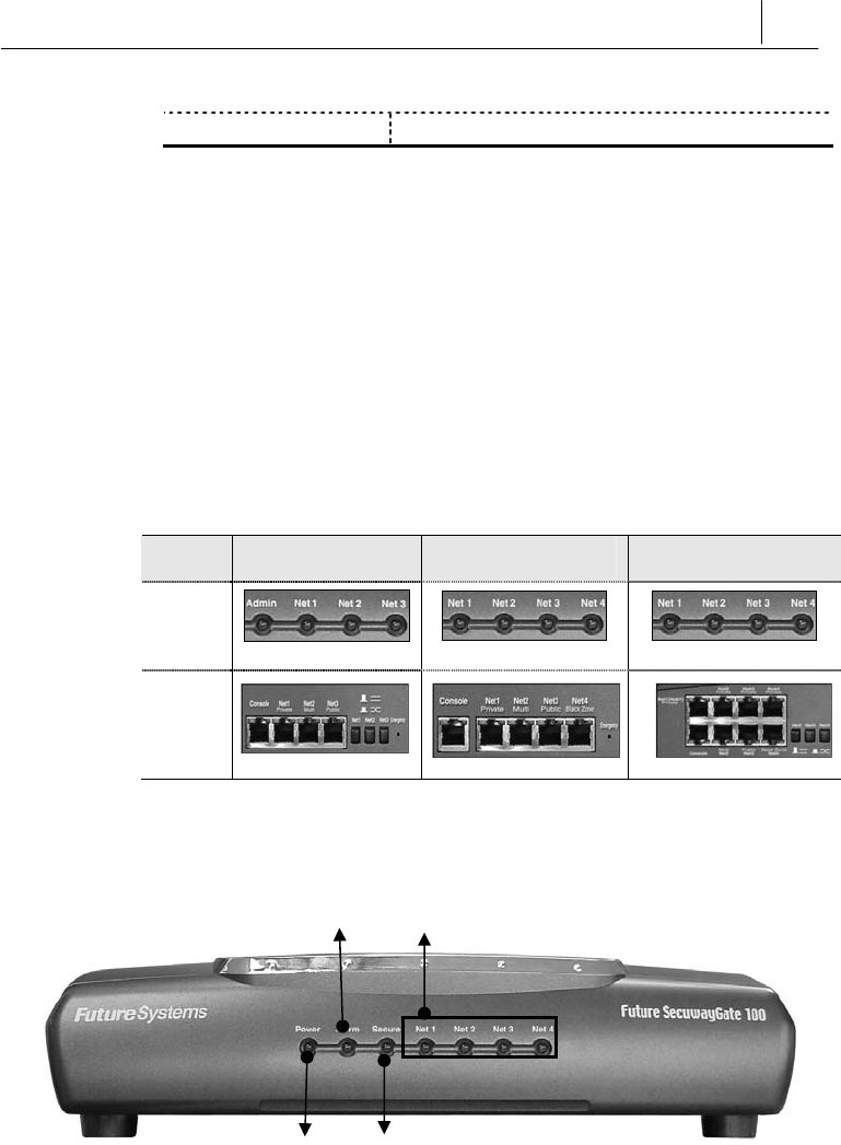
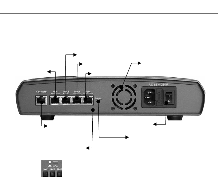
1.2.2 Front and Rear Side of SecuwayGate 100
This section describes LEDs and ports on the front and rear side of
the SecuwayGate 100 module.
Devices for SecuwayGate 100 are divided into 7-port and 3-port,
4-port. ZThe 7-port device is composed of Hub1 ~ Hub4 and Net2 ~
Net4 ports, while Ythe 4-port device has Net1 ~ Net4 ports and
Xthe 3-port device has Net1~Net3 ports.
X3-port Y4-port Z7-port
Front
Rear
Side
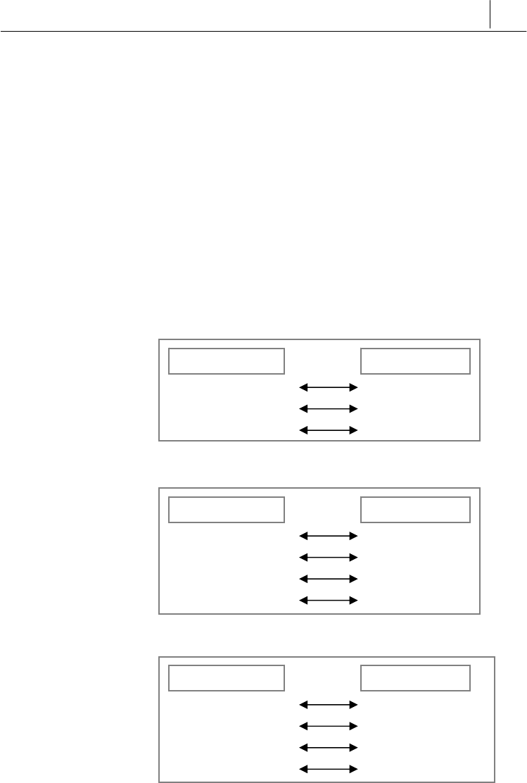
Front Side of SecuwayGate 100
(Type 4- port)
z Power LED
The Power LED is green while the power supply for
SecuwayGate 100 is normal.
Net 1, Net2, Net3 Net4
Secure LED
Power LED
Alarm LED

1-8 Chapter 1
SecuwayGate 2000 Overview
z Alarm LED
The Alarm LED may light on before installation or during operation.
When the Alarm LED is on before installation, that is, before
inserting the smart card for initial configuration, this means that
there is no configured security information. The Alarm LED will
turn off after initial configuration. When the Alarm LED is on during
operation, this signals abnormal operation due to defective
SecuwayGate 100 hardware. For example, when the battery for
saving internal information in SecuwayGate 100 is depleted,
the Alarm LED lights on. In this case, SecuwayGate 100 will
operate properly even if the Alarm LED is on, as long as the power is
supplied. However, once the power is turned off and turned on again,
SecuwayGate 100 will not operate properly since internal
security information has not been saved, and cannot be saved. If the
Alarm LED is on during operation, contact the service center or your
product provider.
z Secure LED
When the Secure LED is green, this means that SecuwayGate
100 internal Security information is properly saved, and that the
intrusion interruption function and the virtual private network
function are available. The Secure LED does not come on before
installation, and only lights when the initial configuration is
completed using the smart card for initial configuration. If the
emergency erase switch is pressed, this deletes the SecuwayGate
100 internal Security information, which turns off the Secure LED.
z Admin LED (Only 3-port)
The Admin LED is on when SecuwayCenter 1000 is in
operation. SecuwayGate 100 may receive changed Secure
information from SecuwayCenter 1000, or SecuwayCenter
2000 may transmit messages to SecuwayGate 100 in order to
periodically check its status. The Admin LED is on when
SecuwayGate 100 communicates properly with
SecuwayCenter 1000. Since the Admin LED is not always on,
1-9
but intermittently blinks when transmitting or receiving information,
the administrator may not notice its activity.
z Net1, Net2, Net3, Net4 LED
The Net LED represents the current state of the communication that
occurs through SecuwayGate 100. Each Net LED blinks during
the communication if the incoming and outgoing packets are
transmitted at the moment. There are 4 Net LEDs, and each of the
LED is connected to the Net1 port (Private), Net2 port (Multi), Net3
port (Public), or Net4 port (Black Zone), on the back.
z Type 3-port
z Type 4-port
z Type 7-port
Net1 Private
Net2 Multi
Net3 Public
Net4 Black Zone
Front-side LEDs Rear-side Ports
Net1 Private
Net2 Multi
Net3 Public
Front-side LEDs Rear-side Ports
Net1 Private(Hub1~Hub4)
Net2 Multi
Net3 Public
Net4 Black Zone
Front-side LEDs Rear-side Ports
1-10 Chapter 1
SecuwayGate 2000 Overview
Rear Side of SecuwayGate 100
(Type 4-port)
Console Port
The Console Port is a serial port for debugging or management
purposes. You can connect to SecuwayGate 100 using the serial
communication program (HyperTerminal). To connect using the
HyperTerminal program, select the communication port to connect
in the terminal mode, set the Bits Per Second field to “38400”, and
set the Flow Control field to “Does not exist.”
Communication Ports
z Net1 Port (Private Port)
The Net 1 port is used to connect the internal network you wish to
protect. Connect the server or network equipment such as switching
equipment and the hub(s) you want to protect, to this port
z Net2 Port (Multi Port)
Consol port
Net1 port
Net2 port
Net3 port
Net4 port
Emergency Erase(Initialize)Switch
Power
V
entilation Openings
RX/TX Changeover Switch
(Only 3-port and 7-p0rt)

1-11
The Multi port physically separates the intranet from the external
network and is usually used to connect a web server, FTP server or
mail server which is open to the public. If the Multi port is connected
to a web server, you can prevent unnecessary access to the intranet
from the external network by applying the security policy so that
access is only allowed through port 80.
z Net3 Port (Public Port )
The Net 3 port is used to receive packets from an external network
or the Internet. The IP address of this Net 3 port (Public port) is
used as the SecuwayGate 100 IP address which a user on an
external network uses to connect to the intranet. Network
equipment connected to the external network, such as a router or
switching equipment, can be connected to this port
z Net4 Port (Black Zone Port )
Black Zone port is used for network security monitoring. If you set
the Net4 port of the SecuwayGate 100 to be used as Black Zone
port in the SecuwayCenter 2000 console, SecuwayGate
100 copies all the inbound and outbound packets of the Net1 and
Net3 ports to the Net4 port.
The IDS solution connected to the Net4 (Black Zone) port
statistically analyzes the packets received from the Net4 port and
reports the results. If the IDS solution found a packet that contains
an illegal intrusion or an access attempt from a harmful site, the IDS
system immediately sends a request to SecuwayGate 100 to
disconnect the session.
For an example of how to set the IDS system, refer to “3.7 IDS”.
Power
Standard input voltage is AC 85~264V (Free Voltage), and standard
power consumption is 25W.

1-12 Chapter 1
SecuwayGate 2000 Overview
Ventilation openings
Ventilation openings are used to cool the internal temperature of the
SecuwayGate 100 due to the heat generated inside. Make sure
that the openings are not blocked by other equipment or devices.
Emergency Erase(Initialize) Switch
The Emergency Erase Switch deletes internal key information in
case of emergencies and restores the factory setting. However, the
Emergency Erase Switch looks similar to the General Reset Button
on the network equipment hardware, which erases all internal key
information. Therefore, it has to be handled with care. Once the
information is erased by pressing emergency erase switch, the
SecuwayGate 100 has to be configured again with the smart
card for initial configuration. In order to intentionally delete security
information configured in SecuwayGate 100, the Emergency
Erase Switch has to be pressed while no power is supplied.
RX/TX Changeover Switch
Using this switch, you can conveniently connect cables to the Net
port regardless of their types (direct cable or cross-over cable).

2-1
C
Ch
ha
ap
pt
te
er
r
2
2
S
Se
ec
cu
uw
wa
ay
yG
Ga
at
te
e
1
10
00
0
I
In
ns
st
ta
al
ll
li
in
ng
g
『Chapter 2. Installing SecuwayGate 100』 describes ways to
install SecuwayGate 100 and cautions for installation. There
are two ways to install the SecuwayGate 100 using
SecuwayCenter 2000: through a smart card or a file issuance.

2-2 Chapter 1
SecuwayGate 2000 Overview
2.1 Instructions for SecuwayGate 100
Installation
Please follow the instructions below to install SecuwayGate 100.
• Make sure to turn the power off and disconnect all communication cables
and power cords before moving SecuwayGate 100.
• Do not install SecuwayGate 100 at a location exposed to direct
sunlight, wetness or any moisture.
•The power cord for SecuwayGate 100 is designed for use with a
grounded plug, so ensure that it is connected at a safe place where it is out
of reach or touch.
• Only authorized personnel are allowed to disassemble SecuwayGate
100 since it might discharge an electrical shock. If the housing case of
SecuwayGate 100 is removed, the TamperProof function activates and
all security information is deleted. All normal operations of SecuwayGate
100 will cease.
y Only the administrator responsible for the maintenance of
SecuwayCenter 2000 is authorized to manage the internal settings of
SecuwayGate 100. No general user can change or edit any internal
settings of SecuwayGate 100..
y The internal and the external networks must be connected through
SecuwayGate 100.
You can set up SecuwayGate 100 by issuing the smart card or
setup file.
z
Installation Option 1 - Smart Card
First, register SecuwayGate 100 in SecuwayCenter 100,
and save the initial setup information in a smart card. Then insert
the smart card into SecuwayGate 100.

2-3
z
Installation Option 2 – Setup File
First, register SecuwayGate 100 in SecuwayCenter 2000,
and save the initial setup information in a file. Then apply the file to
SecuwayGate 100.
2-4 Chapter 1
SecuwayGate 2000 Overview
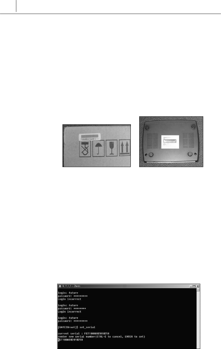
2.2 Verifying SecuwayGate 100 Integrity
All SecuwayGate 100 products are tightly sealed when shipped.
Upon delivery, the administrator must verify that the seal is not
broken.
Also verify that the serial number written on the SecuwayGate
100 package is identical to the one attached on the bottom of
SecuwayGate 100 device.
Package of SecuwayGate 100 bottom of SecuwayGate 100
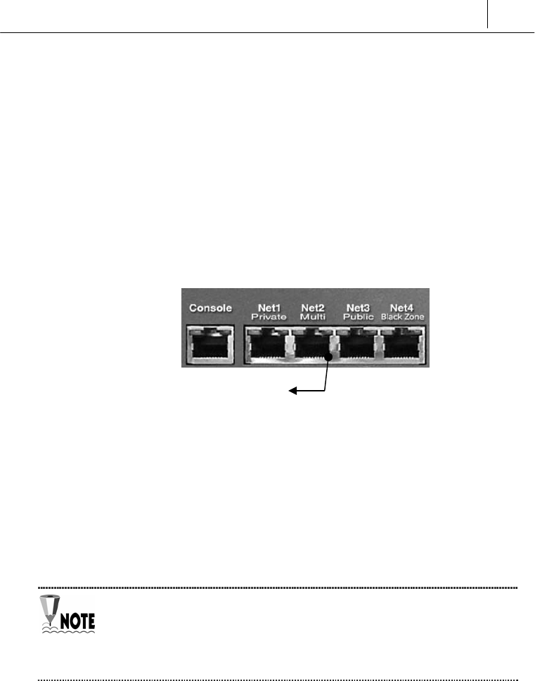
Check the serial number recorded in the flash ROM after you boot
SecuwayGate 100. The following procedures explain how to
check the serial number recorded in the flash ROM.
1. Connect SecuwayGate 100 to the administrator’s PC using the
console cable included in the package.
2. Start HyperTerminal program to log in to SecuwayGate 100.
Enter the login ID and password registered in SecuwayCenter
2000. However, if you login for the first time, you only need to type
in ‘admin’ for the login account.
3. Type ‘set_serial’ command. The serial number is displayed.
If the three serial numbers found on the package, on the rear panel,

2-5
and in the flash ROM of SecuwayGate 100 are not identical to
each other, security of the product is deemed violated. In this case,
contact the SecuwayGate 100 distributor for assistance.

2-6 Chapter 1
SecuwayGate 2000 Overview
2.3 How To Install Using a Smart Card
As a component of SecuwaySuite 2000, RenoGate can be
installed along with SecuwayCenter 2000. The process of
installing RenoGate using SecuwayCenter 2000 is divided
into the following three steps:
There is only Security Administrator account on each
RenoGate.
z Step 1. Connecting RenoGate Cable
Connect the internal and external network with a cable. Depending
on the type of cable, select the switch to either direct or cross cable.
z Step 2. Configuring Key By Inserting Smart Card For Initial
Configuration
To complete configuration, insert the smart card for initial
configuration, which has been issued by SecuwayCenter 2000,
into Renogate. The smart card for initial configuration is issued
by the administrator of SecuwayCenter 2000, and it includes
configuration information. It is sent to the administrator of
RenoGate for installation purposes.
Since the configuration step is automatically performed once the
smart card is inserted in RenoGate, additional external hardware
operations of RenoGate is not necessary during installation.
z Step 3. Checking that the Installation is Complete
Checking that installation is complete can be done through the LED
status of SecuwayGate 100. Also verifications can be made
through check messages from SecuwayCenter 2000, checking
that the security policy is transmitted by the information of the field,
or checking after selecting the status information.
2-7
2.3.1 Connecting SecuwayGate 100 Cable
1. Connect the power supply to SecuwayGate 100 and turn its
switch on.
2. Check whether the LED above the port is lighted in yellow or
green in order to make sure that it has normal physical connection
with the other equipment. If no LED lights up, adjust the port
selection switch.
The cable type selecting switch supports all the ports from Net1 port
Private to Net4 port Black Zone. When the switch is pressed, you can
connect a crossover cable, and if it is not, you can just connect a
general LAN cable as you do with usual network equipment.
If the LED does not light up even after adjusting the port selection switch,
that means the system is not normally connected to the other equipment or
there is an error in the cable. Therefore, you should check the connection
status or replace the cable.
The LED is lights up orange when
connected to 10Mbps LAN, and green
when connected to 100Mbps LAN

2-8 Chapter 1
SecuwayGate 2000 Overview
2.3.2 Inserting Smart Card
The following sequences describes how to do the initial setup of
SecuwayGate 100 by inserting the smart card issued by
SecuwayCenter 2000.
1. As SecuwayGate 100 has no built-in smart card reader, you
need to connect an external smart card reader to the console port,
in order to read the smart card issued by SecuwayCenter
2000.
As SecuwayGate 100 has no built-in smart card reader, you need to
connect a smart card reader to the console port using a connection cable
manufactured separately.
2. When SecuwayGate 100 correctly reads the smart card, a
buzzer sound is emitted and the safety LED turns on. After the
reading has been completed, rebooting occurs automatically and
the power LED turns off and on.
3. After SecuwayGate 100 reboots, it attempts to communicate
with SecuwayCenter 2000 and download the security policy
and any related information.
Connect the smart card to the
connection point at which the
keyboard and the body is
connected to supply power to the
smart card reader. Then, connect
the keyboard to the top of the
smart card.
Connect to the RS232C

2-9
To Check whether SecuwayGate 100 is operating normally,
SecuwayCenter 2000 must be installed because SecuwayGate
100 interacts with SecuwayCenter 2000, the security management
center.
For information on setting up SecuwayGate 100 from
SecuwayCenter 2000, refer to the SecuwayCenter 2000
Administrator Guide.

2-10 Chapter 1
SecuwayGate 2000 Overview
2.3.3 Checking Installation
By checking the front LEDs, you can confirm whether the
SecuwayGate 100 installation is completed.
z Before Installation
The Power LED at the front lights up green.
The Alram LED at the front lights up red.
z After Installation
Both of the Power and Secure LEDs light up green.
If a cable is connected to a port at the rear, the corresponding Net
LED flickers or lights up.
Another method of confirming the connection status is to send a test
message from SecuwayCenter 2000 and see if there is a
response. You can also confirm the successful installation of
SecuwayGate 100 by viewing the contents of the field to see if
the security policy has been transmitted or by viewing the status
information.

2-11
2.3.4 Procedures to re-load smart card information
into SecuwayGate 100 during operation
There may be an instance when the smart card information has to be
read again while SecuwayGate 100 is in operation, or a smart
card issued for another SecuwayGate 100 has been inserted
and loaded. In this case, the existing SecuwayGate 100
configuration needs to be erased, and the new smart card
information needs to be loaded.
To erase the security configuration, turn off SecuwayGate 100,
press the emergency erase switch for 4 to 5 seconds, and turn on the
system. Insert the correct smart card.
SecuwayGate 100 does not automatically read the information
of any inserted smart card for initial configuration, if it is already
configured.
2-12 Chapter 1
SecuwayGate 2000 Overview
2.4 How To Install Using File Issuance
When importing initial setting information into SecuwayGate
100, you can use a file issued from SecuwayCenter 2000
instead of using a smart card. If you connect a hyper-terminal
program to SecuwayGate 100 and send the file, Secuway
Gate 100 will be completely installed.
There is only Security Administrator account on each SecuwayGate
100
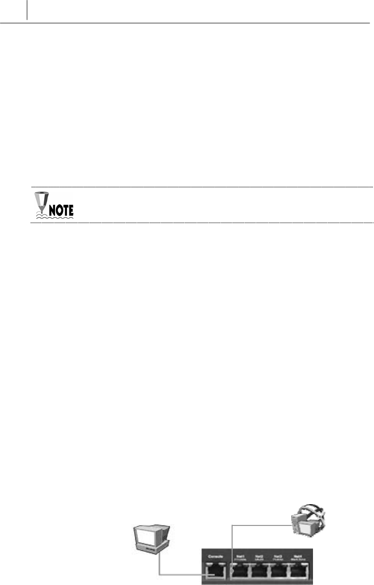
2.4.1 Running Hyper Terminal Program
Issue the SecuwayGate 100 setup file from SecuwayCenter
2000 and save it on a diskette. Insert the diskette into
SecuwayGate 100 and connect SecuwayGate 100 to your
PC using the Hyper Terminal to apply the file
z
Running Hyper Terminal
Connect the console’s connector to the serial port on the PC and
then to the RS-232C port of SecuwayGate 100 (using a LAN
cable) as shown in the following figure.
Connect the actual network or SecuwayCenter 2000 directly to
the port, which will be connected to SecuwayCenter 2000.
Once the initial setup is completed, be sure to receive the security
policies from SecuwayCenter 2000.
RS-232C port
LAN
Serial port
Secuway
Center 2000
PC in which the
setup file is inserted

2-13
After the connection is established run the Hyper Terminal program
in the PC, where you inserted the initial setup file.
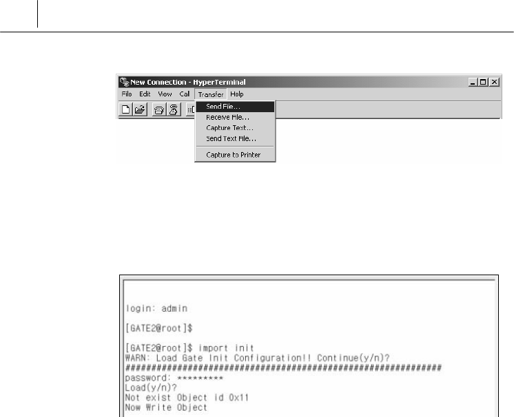
2.4.2 Imprting File into SecuwayGate 100
1. After running the hyper-terminal, enter the password as
shown below to log on to SecuwayGate 100. When
successfully connected, run “ import init.”
The SecuwayGate 100 will only accept 3 failed login attempts for the
Security Administrator account, and will the deny login attempts for a period
of five minutes.
When the SecuwayGate 100 Security Administrator account is inactive
for 2 minutes, then it will logoff automatically. This functionality can be
disabled by the Security Administrator for that SecuwayGate 100, if
required.(see “sv command” in chapter 5 Console Commands)
2. When the following message is displayed, type ‘y’.
3 Select <Send File…> from the <Transfer> menu, and select the
SecuwayGate 100 authentication file (.gat) where the
authentication information is saved.
2-14 Chapter 1
SecuwayGate 2000 Overview
4. When the file is completely imported to SecuwayGate 100,
enter the password and type [y]. SecuwayGate 100 will
begin initial setup process and then automatically restart.

2-15
2.4.3 Checking Installation
Checking that installation is complete can be done through the LED
status of SecuwayGate 100. Also verifications can be made
through check messages from SecuwayCenter 2000, checking
that the security policy is transmitted by the information of the field,
or checking after selecting the status information.
z Before installation
- The Power LED on the front side of the system is lit green.
- The Alarm LED on the front side of the system is lit red.
z After installation
- After reading the smart card for initial configuration, the Power
and Secure LEDs turn on.
- The Power and Secure LEDs are turned on in green.
- The Alarm LED is turned off.
- If there is a cable connected to the rear side of the system, the Net
LED on front side blinks or is lit.

3-1
C
Ch
ha
ap
pt
te
er
r
3
3
S
Se
ec
cu
uw
wa
ay
yG
Ga
at
te
e
1
10
00
0
C
Co
on
nn
ne
ec
ct
ti
io
on
n
E
Ex
xa
am
mp
pl
le
es
s
『Chapter 3. SecuwayGate 100 Connection Examples』describes
ways to connect SecuwayGate 100 in various network
environments. The focus is laid on how to connect each port of
SecuwayGate 100 and how to configure the SecuwayGate
100 information in SecuwayCenter 2000.
3-2 Chapter 4
Operating SecuwayGate 2000
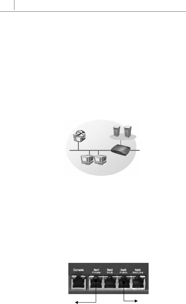
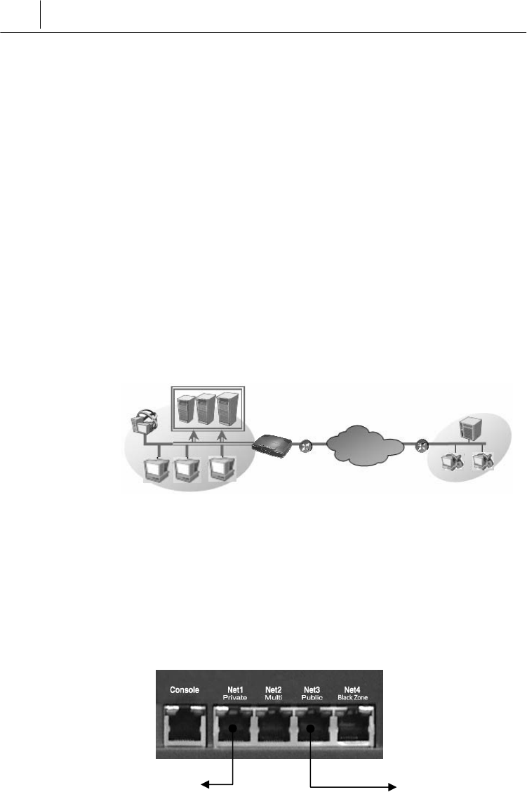
3.1 Connection Example To Secure Internal
Server
SecuwayGate 100 provides an intrusion interruption function
based on the security policy to control access attempts to the server
within the internal network. SecuwayGate 100 provides a
Stateful Inspection filtering function to cover various user
environments. In addition, SecuwayGate 100 provides inter-
operability with SecuwayClient 2000 in order to provide secure
communication through encryption.
Internal Network
Port Connections
The following figure shows how to build a physical network
connection for a secure internal server on the rear side of
SecuwayGate 100.
SecuwayGate 100
Server
SecuwayCenter 2000
Connect to the external network or
connect the hub or switching device
to the Net3 port.
Connect the server
or hub cable to the
Net1 port.

3-3
Connect the server or hub cable to the Net1 port and the external
network to the Net3 port. In this way, SecuwayGate 100 is
topologically and physically located between the secure server and
the external network to support the user access control, user
authentication, and encrypted communication.
Connect SecuwayCenter 2000 to the Net1 (Private) or Net2
(Multi) port of the SecuwayGate 100.
3-4 Chapter 4
Operating SecuwayGate 2000
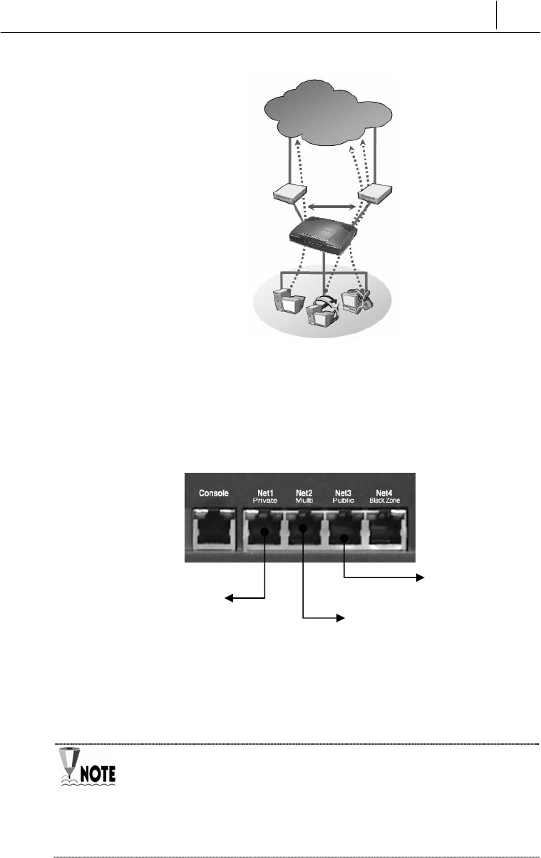
3.2 Internal Network Security Example (Firewall)
SecuwayGate 100 supports a firewall feature and lets your
organization control inbound packets according to a set of
predefined security policies.
Internal Network External Network
Port Connections
The following figure shows how to build a physical network
connection for a firewall at the side panel of SecuwayGate 100.
Connect the internal network cable to the Net1 port and the router
cable to the Net3 port, Net2 port connect server that are
communicates with external network. In this way, SecuwayGate
100 is topologically and physically located between the secure
server and the external network to control accesses to the internal
network.
Connect to router
connect the cable
that connected the
network and router.
SecuwayGate 100
Connect to sever
3-5
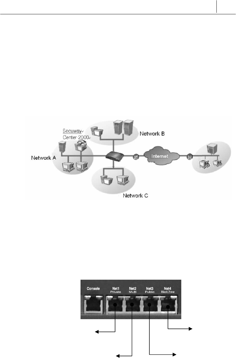
3.3 Connecting as Gateway Mode
SecuwayGate 100 can be installed separating the internal
network into 3 sub-networks of A and B,C. Using SecuwayGate
100 installed following this example, communication between sub-
networks as well as communication between the internal and
external network can be controlled, based on valid network
configuration and security policy.
Internal Network External Network
Port Connections
The following figure shows how to build a physical network
connection for a gateway mode on the rear side of SecuwayGate
100.
You can connect by configuring it as different networks or segments
at each of the port from Net1 ~ Net4.
Connect with router or
swit ching equipment
conne cted to internal
network C
Connect with router
connected to the
external network.
Connect with router or swit
ching equipment conne cted
to internal network B
Connect with router or
switching equipment
connected to internal
network A
.
SecuwayGate 100
3-6 Chapter 4
Operating SecuwayGate 2000
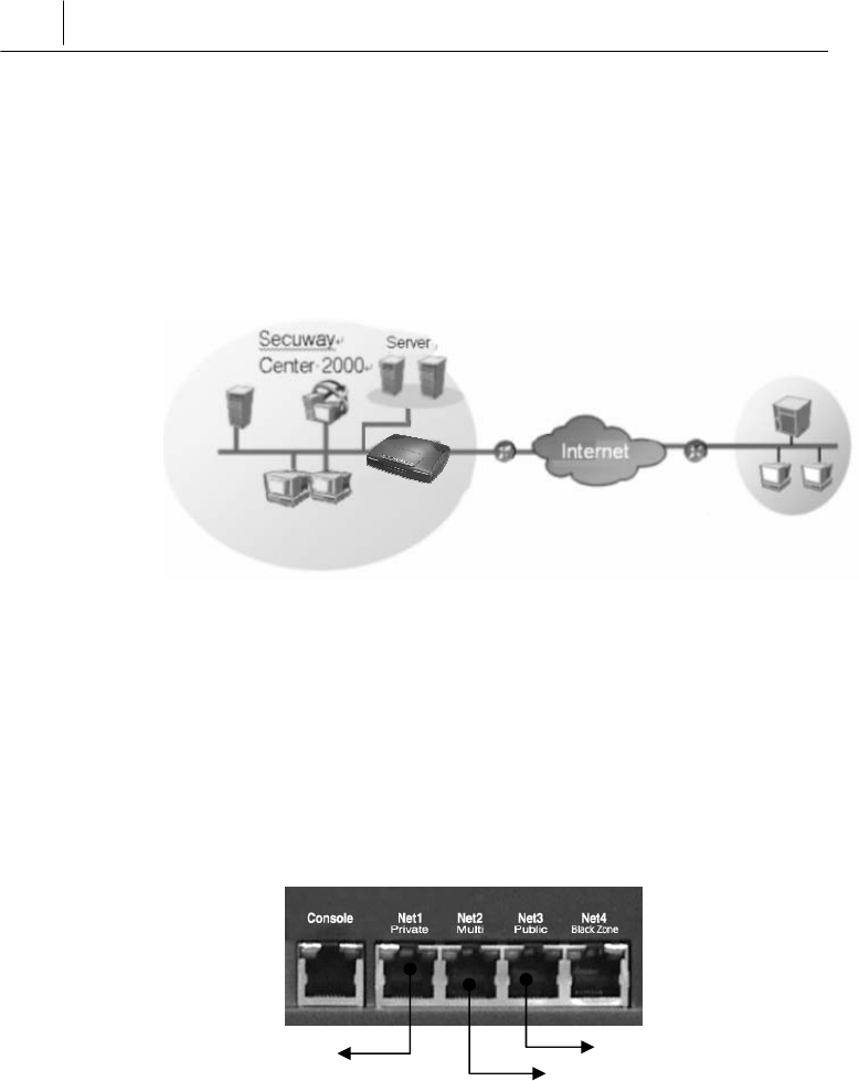
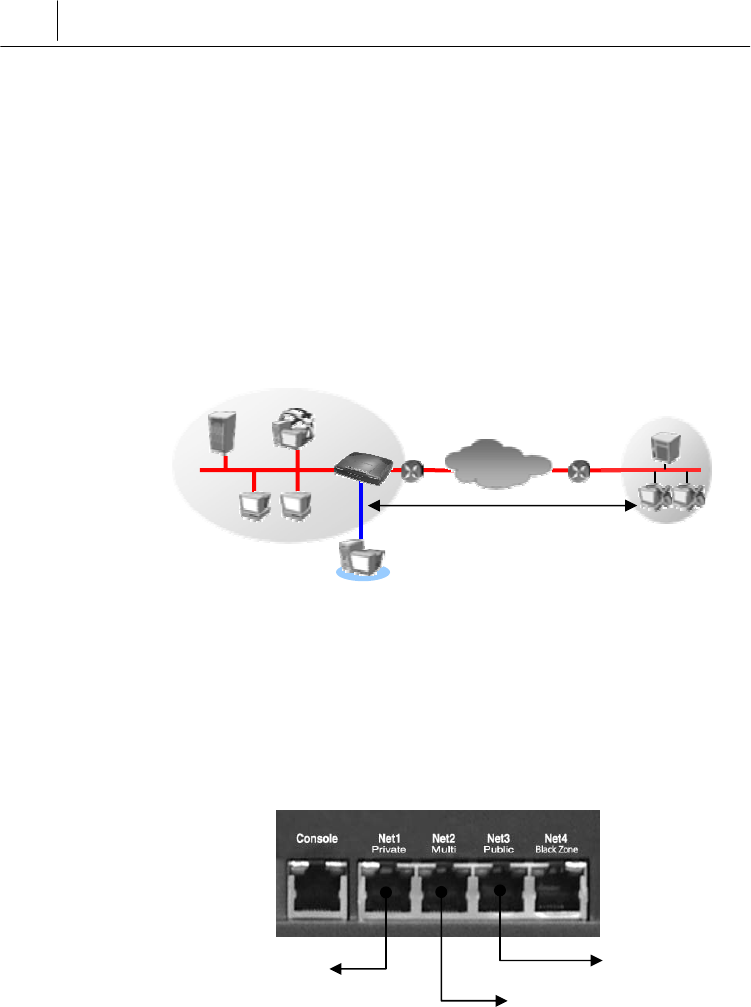
3.4 Connecting to Provide VPN
You can connect SecuwayGate 100 of the headquarter and
SecuwayGate 100 of the branch office to perform the VPN
function. To enable the VPN function, you need a pair of
SecuwayGate 100 devices working together or
SecuwayClient 2000 installed to support encrypted
communication.
Main Office Network Branch Office Network
Port Connections
The following figure shows how to build a physical network
connection for VPN on the rear side of SecuwayGate 100.
Connect the internal network cable to the Net1 port and the router
cable to the Net3 port, Net2 port connect VPN server that are
communicates with external network. In this way, SecuwayGate
100 is topologically and physically located between the secure
server and the external network to control accesses to the internal
network.
VPN Server
Connected to Net2(Multi)
Internet
Encryption Section SecuwayClient 2000
SecuwayCenter 2000
SecuwayGate 100
Connected to router.
Connect to VPN server
Connect a cable, which
is connected to router
and internal network.
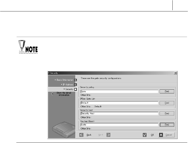
3-7
To install SecuwayGate 100 as a VPN gateway, the ‘Security’
properties of SecuwayGate 100 must be set as shown in the following
figure in SecuwayCenter 2000. For information on how to install, refer
to the Administrator Guide
3-8 Chapter 4
Operating SecuwayGate 2000
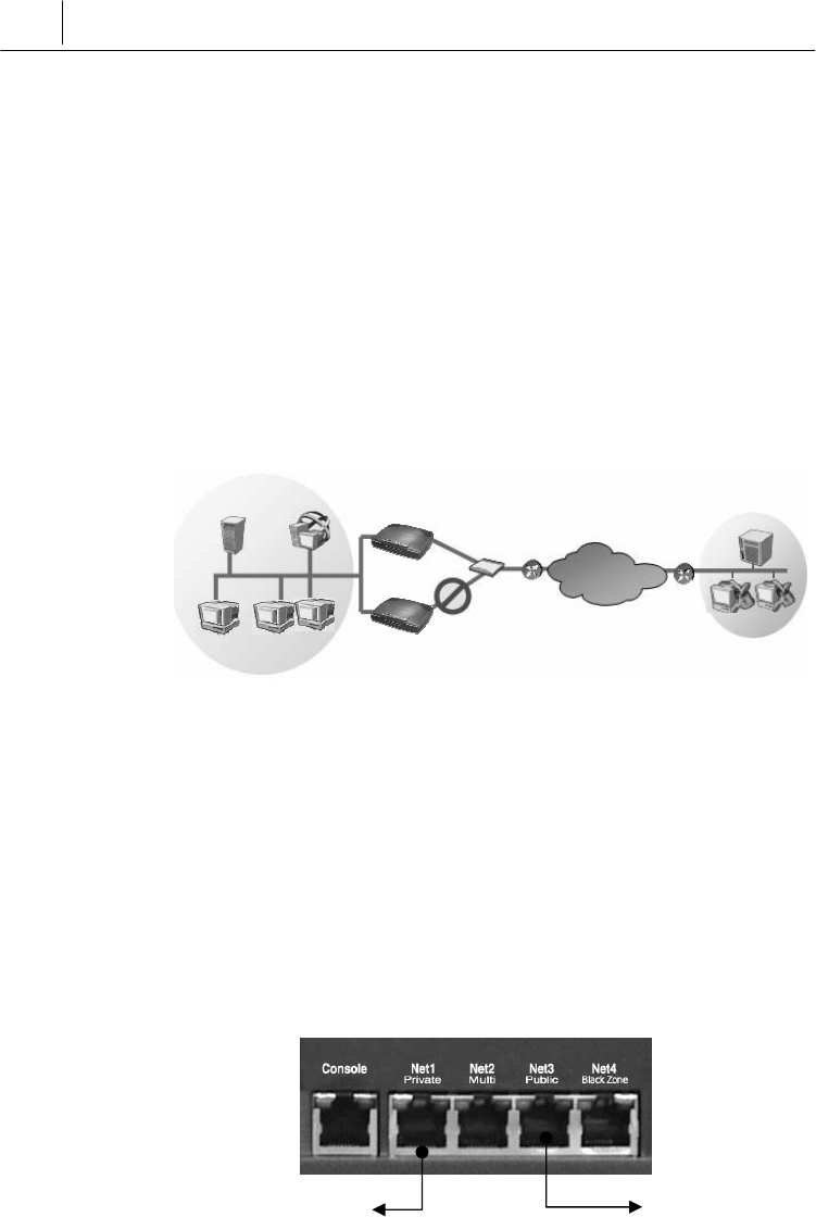
3.5 High Availability Example
3.5.1 Failover Example
If you install the system as a gate backup feature using the fail-over
feature, which is the high availability feature of VPN itself, you can
take backup measures without a separate L4 switch. This is used
when there are too many VPN gates, or you are using a critical
application during VPN communication.
Internal Network External Network
Port Connections
The following figure shows how to build a physical network
connection on the rear side of the SecuwayGate 100 to enable
the HA failover function.
The port connections of the main Gate and auxiliary Gate are
identical
In the SecuwayCenter 2000 setup window, configure the main
gate and the auxiliary gate, and then register each other’s IP address.
Also set up the interface to connect the rear ports and the UDP
port to communicate through, the two SecuwayGate 100
Internet
Server
SecuwayGate 100
STOP
Connect a cable, which is
connected to internal net
work.
SecuwayClient 2000
SecuwayGate 100
Hub
SecuwayCenter 2000
Connected to switch.
3-9
systems will operate correctly
When configuring the two SecuwayGate 100 as Failover feature,
they should be in connected situation. If you use Net1 and Net3 ports,
you don’t have to connect Net2 port additionally. However, if the
traffic volume of Net1 and Net3 ports is high, you can also use Net2 or
Net4 port. . In such a case, the two SecuwayGate 100 devices
must be connected to a switching device.
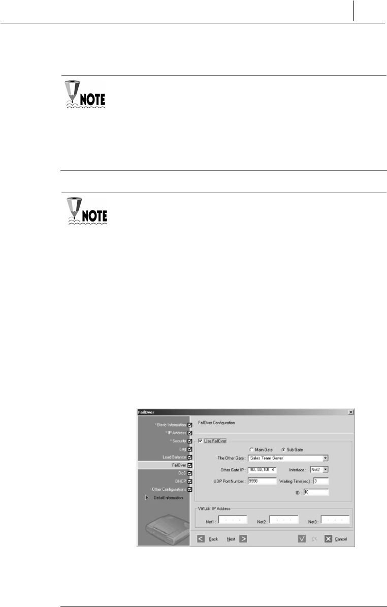
To install SecuwayGate 100 as failover-enabled gates, the main
and sub gates must be specified in the ‘Failover’ menu of
SecuwayCenter 2000, as shown in the following figure. For more
information about the failover configuration, refer to the Administrator
Guide.
If the main and sub gates are connected through the Net2 (Multi) port,
you may configure the main gates as shown in the following figure.
First, when you register the IP address for main gate, set the ‘Valid
Network’ as the Net2 port of the sub gate. Likewise, when you register
the sub gate, you can simply set the Net2 port of the main gate as the
‘Valid Network.
When configuring ‘Failover’, check the other gate and set each item
as shown below.
On the screen above, enter the IP address of the port that performs
the Failover function at other gate in ‘Other Gate IP’, and select the
port to perform Failover at the current gate in ‘Interface’.
3-10 Chapter 4
Operating SecuwayGate 2000
3.5.2 Server Load Balancing Example
By using the server load-balancing feature, which is the high
availability feature of the VPN itself, you can prevent
communication traffic jam to one server that may cause
overload in the server.
When an external or internal user tries to access the FTP servers
that have the same features, the user must connect only through the
representative virtual IP address that has been set in the
SecuwayGate 100. Therefore, when a communication traffic
jam occurs, the SecuwayGate 100 can distribute the services
among different servers.
Port Connections
The following figure shows how to build a physical network
connection on the rear side of SecuwayGate 100 to implement
the server load-balancing
Connect Net1 port to the cable of the internal network, and Net3
Internal Network External Network
FTP Server
It is connected to Hub.
connect a cable, whi
ch has connected in
ternal networ
k
SecuwayClient 2000
SecuwayCenter2000
SecuwayGate 100
Internet
Internet

3-11
port to the router. In other words, SecuwayGate 100 is
physically installed between the server in the internal network that
performs the same function and internal/external network to
support uniform communication to each server. Adjust the RX/TX
changeover switch on the right of the ports according to the cable
type
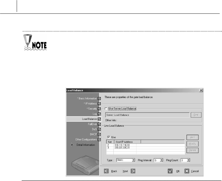
To install SecuwayGate 100 as a load balancing -enabled gate, the use
of server load balancing feature must be set in the ‘Load Balance’ menu of
SecuwayCenter 2000, as shown in the following figure. For more
information, refer to SecuwayCenter 2000 Administrator Guide.

3-12 Chapter 4
Operating SecuwayGate 2000
3.6 ADSL Line Load-Balancing Example
By connecting two WAN lines using the two ports of Secuway
Gate 100, the system can be immediately switched to another line
to enable communication when the communication is disabled due
to an error in one line,
In addition, since SecuwayGate 100 supports two ADSL lines
simultaneously, concerns about ADSL quality can be
eradicated and load balancing is provided for lines to ensure
optimum Internet environment.
SecuwayGate 100 calculates the hash values for both source
and destination IP addresses to select a line to transmit the relevant
packets. If the selected line is currently down, the other line is
automatically selected to forward the packets.
S
T
O
P
ISP A ISP B
Trouble ISP B
ISP B ISP A
SecuwayGate 100
Internet Internet
Control traffic
Maintain Internet connection
- Support two port Load Balance
- Expand bandwidth
Internal network Internal network
SecuwayGate 100
3-13
Port Connections
The following figure shows how to build a physical network
connection on the rear side of SecuwayGate 100 to implement
the ADSL line load-balancing feature.
SecuwayGate 100 can connect two WAN lines using two ports.
After connecting the ADSL lines to Net2 port and Net3 port of
SecuwayGate 100, you can configure them in such a way as
to prevent concentration in one line for the transmitted and
received traffics and distribute the communication
For the connected ADSL lines, you can either use a fixed IP address (using
an IP address in a fixed way), or a floating IP address (when IP address
changes every time you connect). Choosing a fixed IP address or a floating
IP address in modem type is the responsibility of the SecuwayCenter
2000 administrator
Internal Network
It is connected to ADSL line
It is connected to ADSL line
Connect a cable, which
has connected router
and internal network
.
Internet
Line Load balance
SecuwayGate 100
3-14 Chapter 4
Operating SecuwayGate 2000
To install SecuwayCenter 2000 as an ADSL Line load balancing-
enabled gate, the use of line load balancing feature must be set in the
‘Load Balance’ menu of SecuwayCenter 2000 as shown in the
following figure. Note that the IP address of each port and the modem type
need to be specified as well. For more d information, refer to Administrator
Guide.

3-15
3.7 IDS (Intrusion Detection System) Connection
Example
You can install an intrusion detection system using Net4 (Black
Zone) port provided by SecuwayGate 100 itself. The Net4
(Black Zone) port cannot be detected with its inherent
characteristics, so the outside network doesn’t know the existence of
the intrusion detection system. Therefore, it can operate more
effectively in a security management aspect. The following table
shows the list of IDS solutions that are interoperable with
SecuwayGate 100.
In the 3 Port, IDS using Net2(Multi) Port
Product Version Company
SniPer V 2.0 WINS Technet Co., Ltd
Siren V 3.0 Penta Security Systems Inc
NetSpecter IDS V 1.2 NetSecureTechnologie
NeoWatcher@ESM N-
IDS V 3.0 INZEN.Com
SecuwayGate 100 transmits the send/receive packets to Net4
(Black Zone) port at the same time, thus allowing the intrusion
detection system to analyze them.
Internal Network External Network
Internet
Server
IDS
SecuwayGate 100 SecuwayClient 2000
SecuwayCenter
2000
3-16 Chapter 4
Operating SecuwayGate 2000
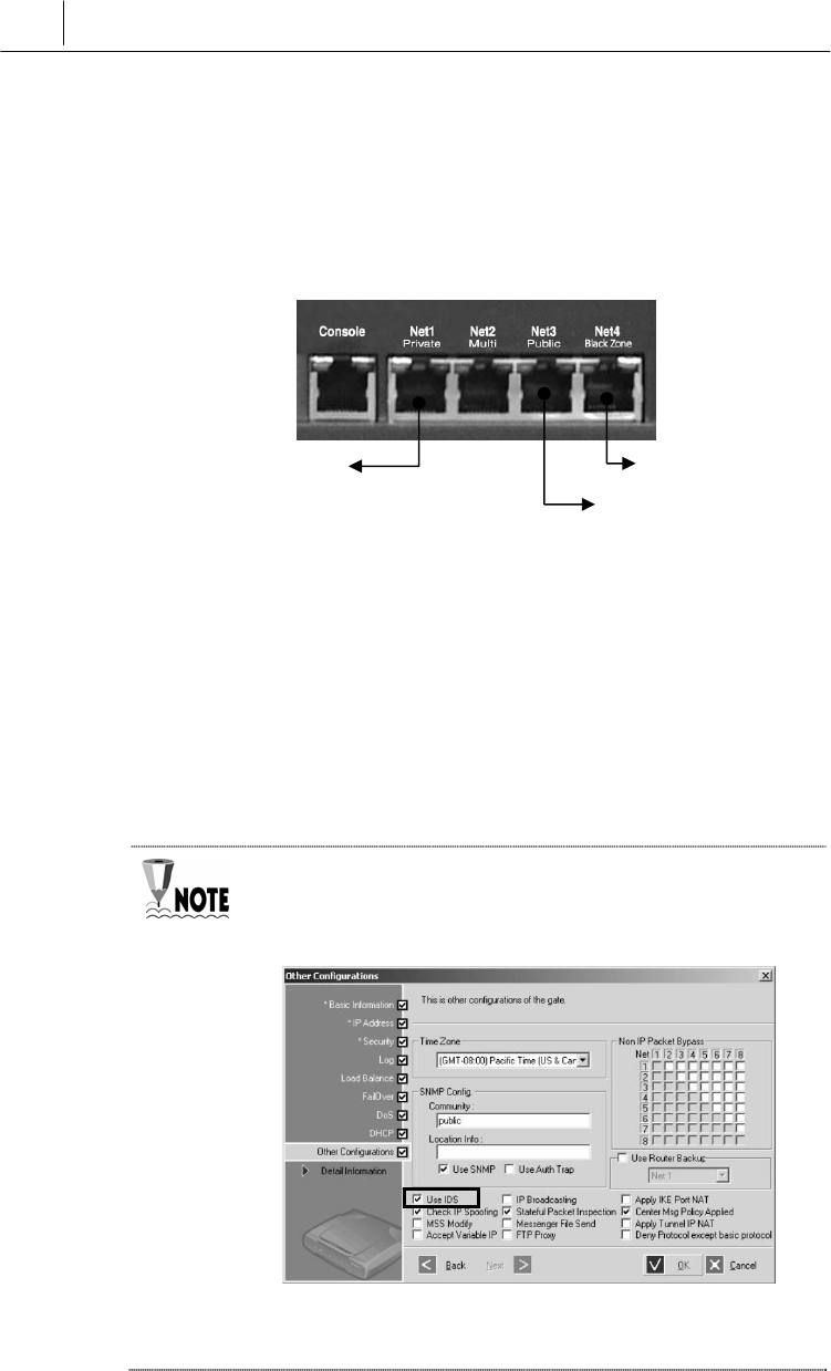
Port Connections
The following figure shows how to build a physical network
connection for IDS-enabled configuration on the rear side of
SecuwayGate 100.
Connect an IDS solution to the Net4 (Black Zone) port of
SecuwayGate 100 to enable the IDS solution to analyze the
inbound and outbound packets. Connect the Web server to the Net2
(Multi) port of SecuwayGate 100. In this way, the internal
network is technically separated from the external network and
SecuwayGate 100 is able to control the incoming and outgoing
packets according to the security policies stored in the
SecuwayGate 100.
To connect an IDS solution to the SecuwayGate 100, the ‘Use
IDS’ must be selected in SecuwayCenter 2000, as shown in
the following figure.
You can check the operation status when SecuwayGate 100
and the IDS solution are interoperated in the ‘Log’ menu of
It’s connected to the
intrusion detection system.
It is connected to
router
.
Connect a cable, which
has connected internal
network
.
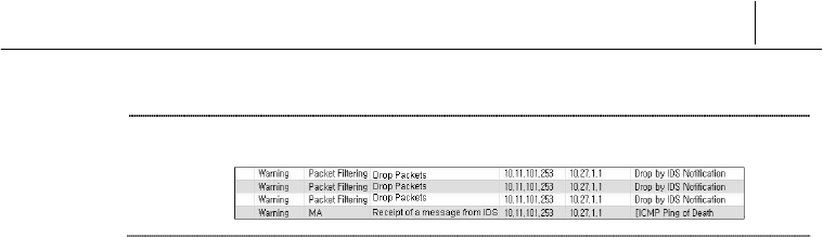
3-17
SecuwayCenter 2000.