Grandstream Networks UCM6510 IP PBX User Manual
Grandstream Networks, Inc. IP PBX Users Manual
UserManual.wiki
>
Grandstream Networks
>
UCM6510 User Manual
>
Users Manual
Contents
1.
Users Manual
2.
User Manual
Users Manual
Navigation menu
Upload a User Manual
Namespaces
Wiki Guide
HTML
PDF
Info
Views
User Manual
Discussion / Help
Navigation
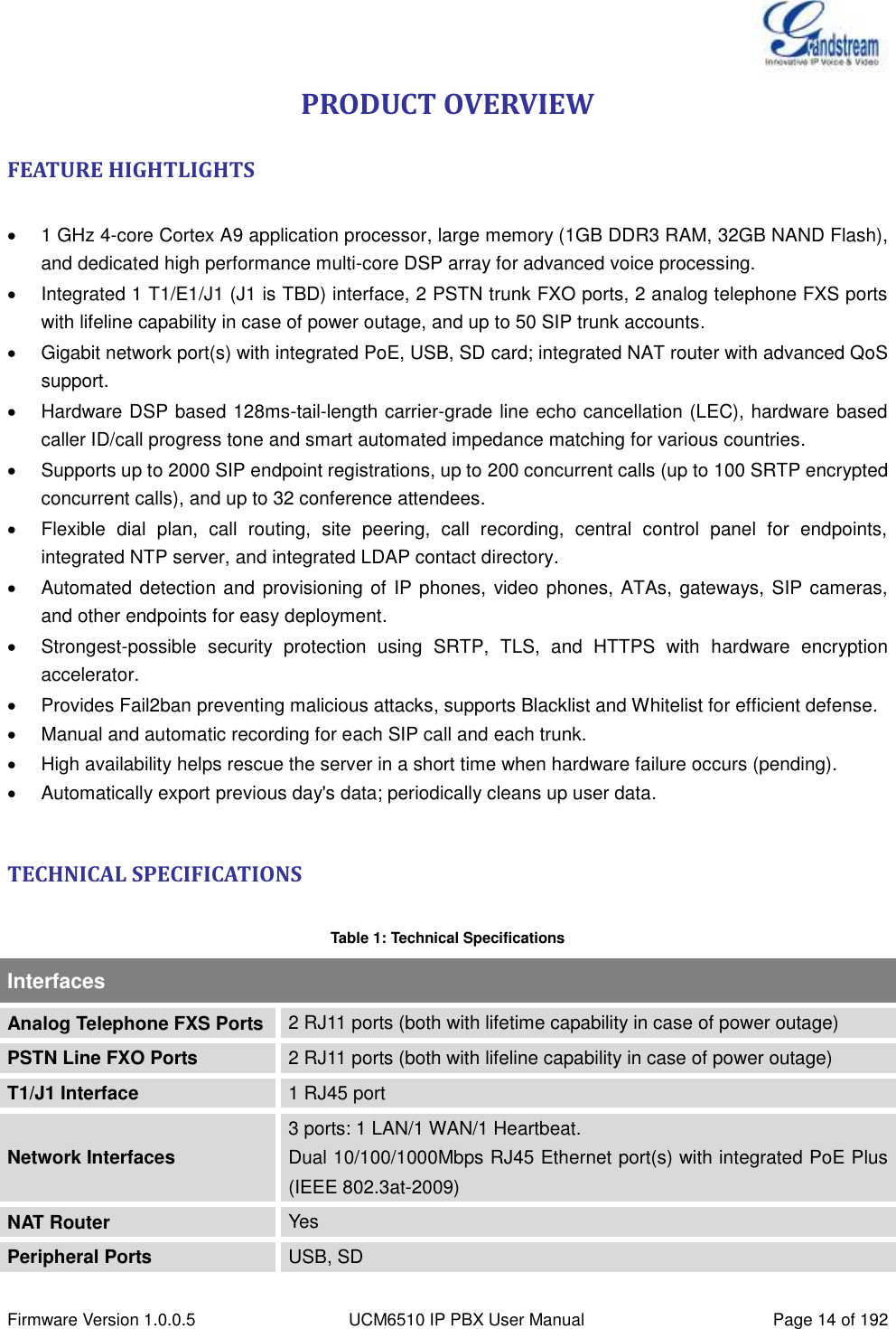
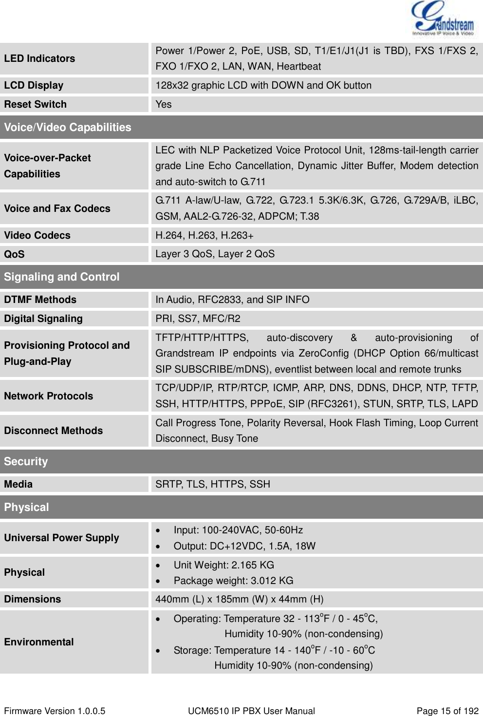
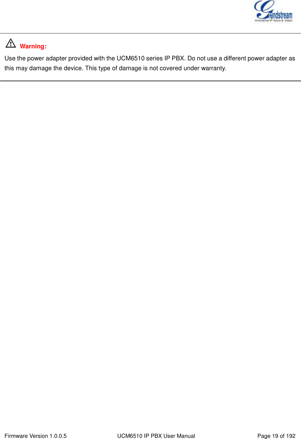
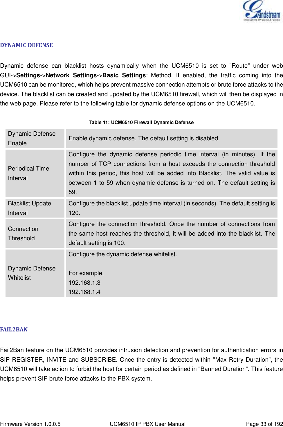
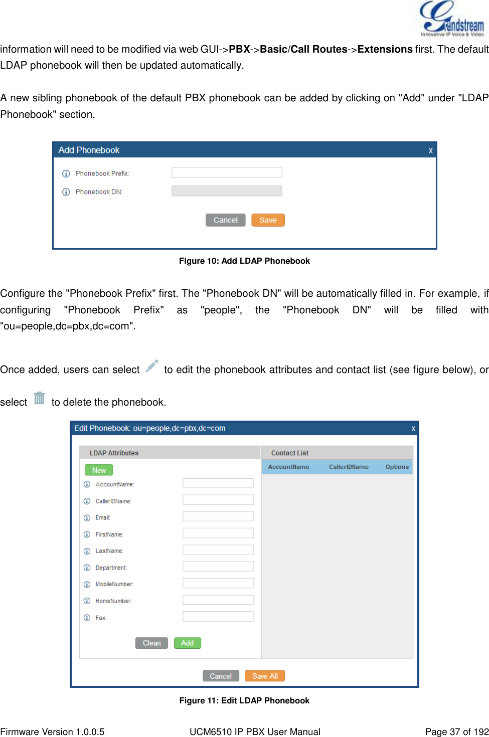
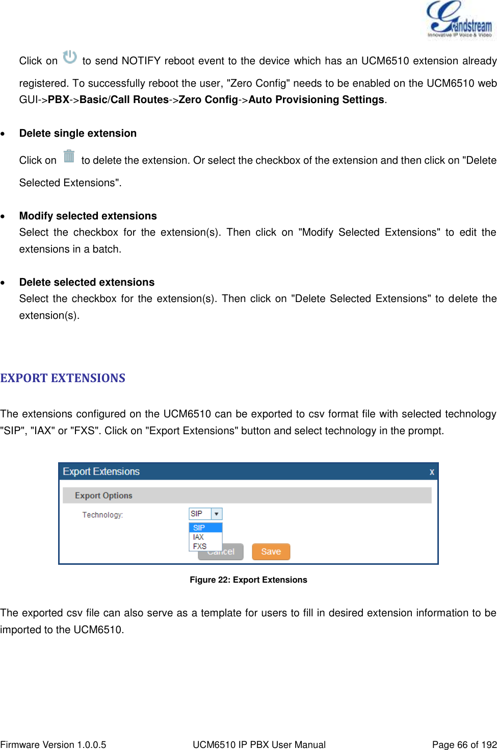
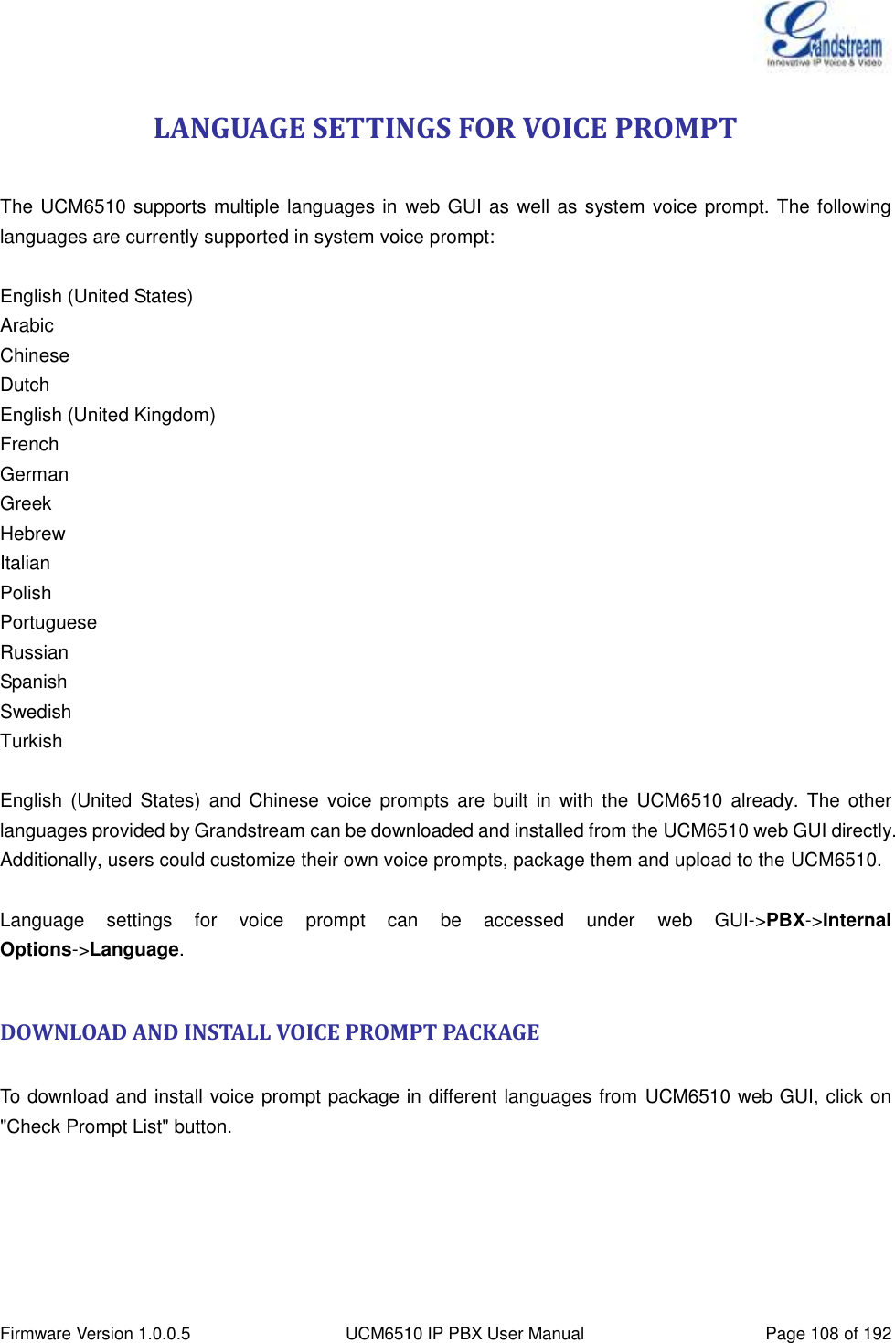
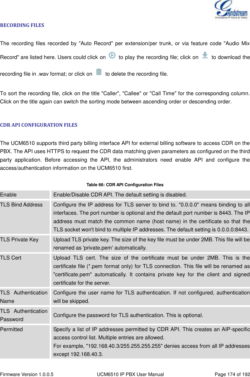
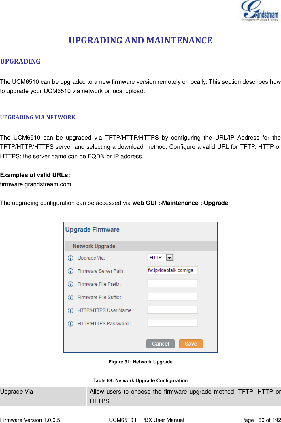
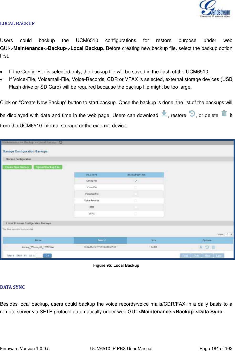
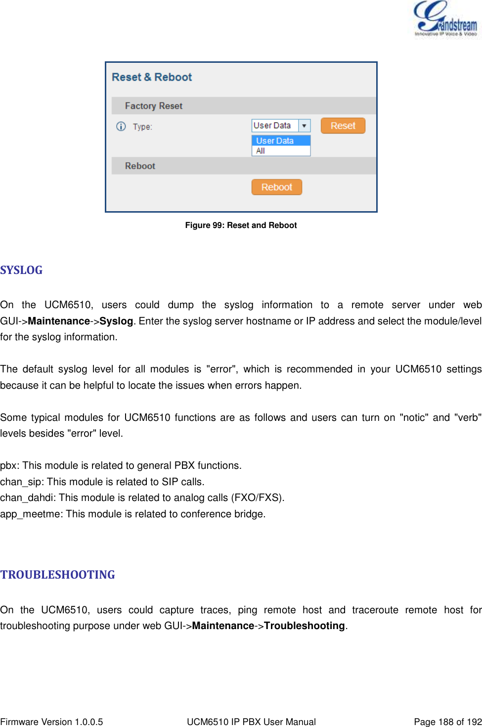
![Firmware Version 1.0.0.5 UCM6510 IP PBX User Manual Page 20 of 192 GETTING STARTED The UCM6510 provides LCD interface, LED indication and web GUI configuration interface. The LCD displays hardware, software and network information. Users could also navigate in the LCD menu for device information and basic network configuration. The LED indication at the front of the device provides interface connection and activity status. The web GUI gives users access to all the configurations and options for UCM6510 setup. This section provides step-by-step instructions on how to use the LCD menu, LED indicators and web GUI of the UCM6510. Once the basic settings are done, users could start making calls from UCM6510 extension registered on a SIP phone as described at the end of this section. USE THE LCD MENU Default LCD Display By default, when the device is powered up, the LCD will show device model (e.g., UCM6510), hardware version (e.g., V1.5A) and IP address. Press "Down" button and the system time will be displayed (e.g., 2014-05-15 14:20). Menu Access Press "OK" button to start browsing menu options. Please see menu options in [Table 3: LCD Menu Options]. Menu Navigation Press the "Down" arrow key to browser different menu options. Press the "OK" button to select an entry. Exit If "Back" option is available in the menu, select it to go back to the previous menu. For "Device Info" "Network Info" and "Web Info" which do not have "Back" option, simply press the "OK" button to go back to the previous menu. Also, the LCD will display default idle screen after staying in menu option for 15 seconds. LCD Backlight The LCD backlight will be on upon key pressing. The backlight will go off after the LCD stays in idle for 30 seconds. The following table shows the LCD menu options.](https://usermanual.wiki/Grandstream-Networks/UCM6510.Users-Manual/User-Guide-2378753-Page-21.png)
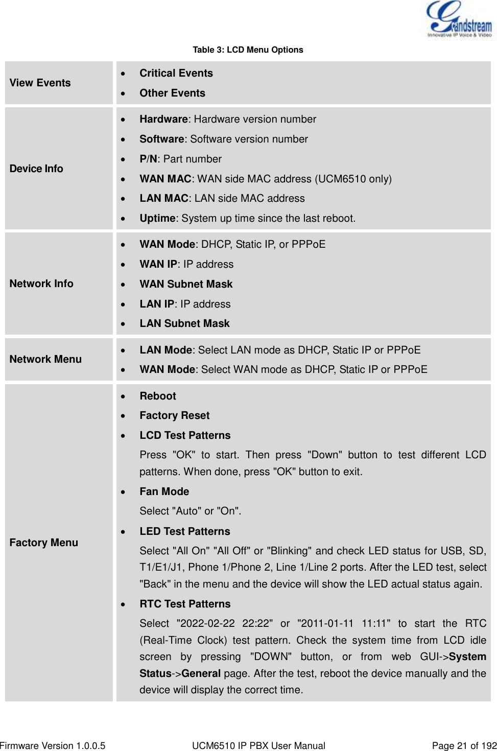
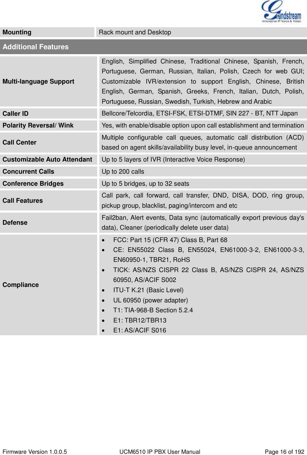
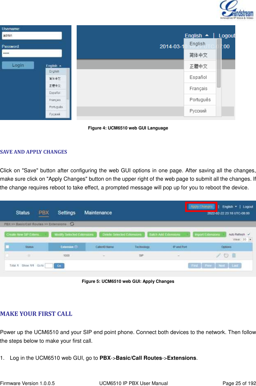
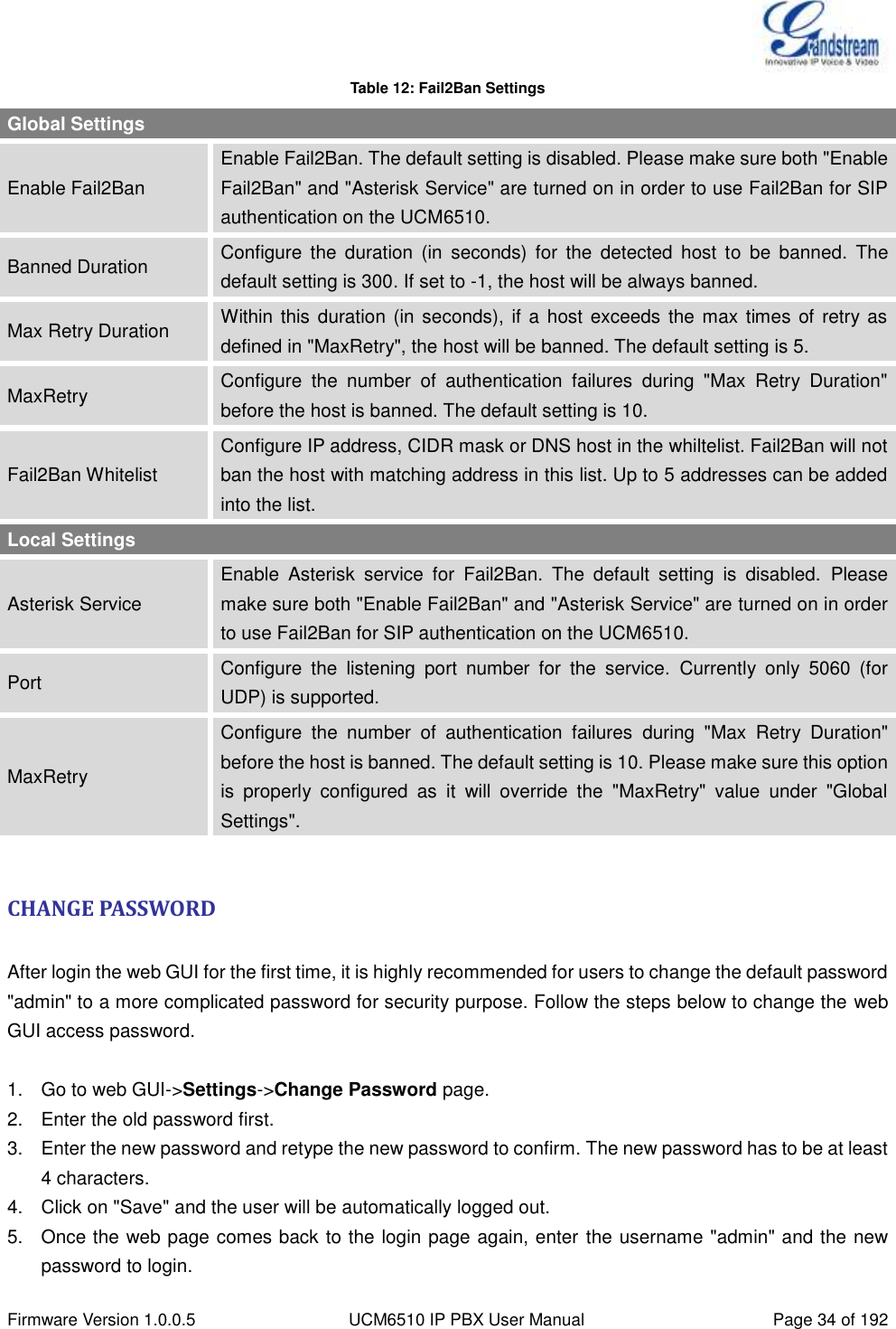
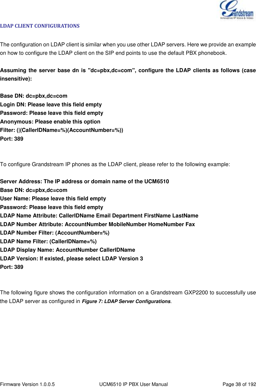
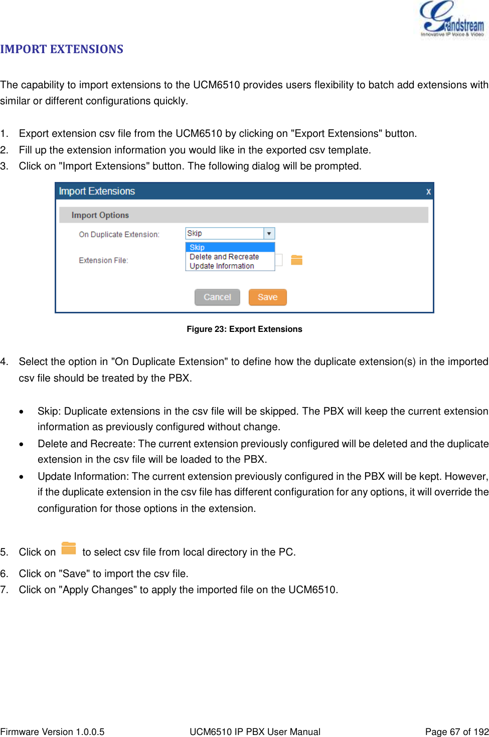
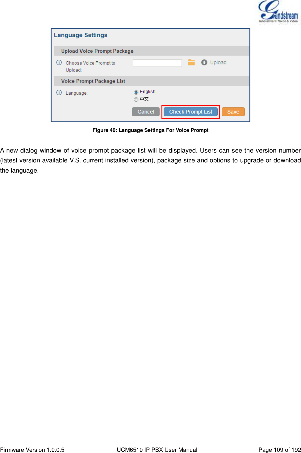
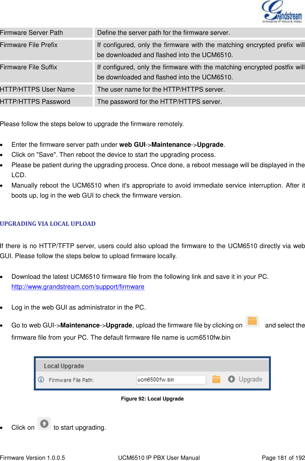
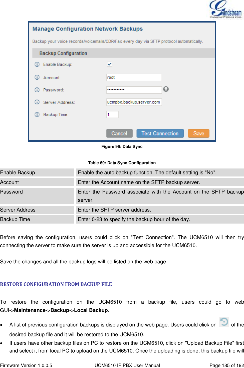
![Firmware Version 1.0.0.5 UCM6510 IP PBX User Manual Page 23 of 192 Figure 3: UCM6510 web GUI Login Page To access the web GUI: 1. Connect the computer to the same network as the UCM6510. 2. Ensure the device is properly powered up and shows its IP address on the LCD. 3. Open a web browser on the computer and enter the IP address in the address bar. The web login page will display as shown in [Figure 3: UCM6510 web GUI Login Page]. 4. Enter the administrator’s login and password to access the web configuration menu. The default administrator's username and password is "admin" and "admin". It is highly recommended to change the default password after login for the first time. Note: By default, the UCM6510 has "Redirect From Port 80" enabled. Therefore, if users type in the UCM6510 IP address in the web browser, the web page will be automatically redirected to the page using HTTPS and port 8089. For example, if the LCD shows 192.168.40.167, please enter 192.168.40.167 in your web browser and the web page will be redirected to: https://192.168.40.167:8089 The option "Redirect From Port 80" can be configured under the UCM6510 web GUI->Settings->HTTP Server.](https://usermanual.wiki/Grandstream-Networks/UCM6510.Users-Manual/User-Guide-2378753-Page-24.png)
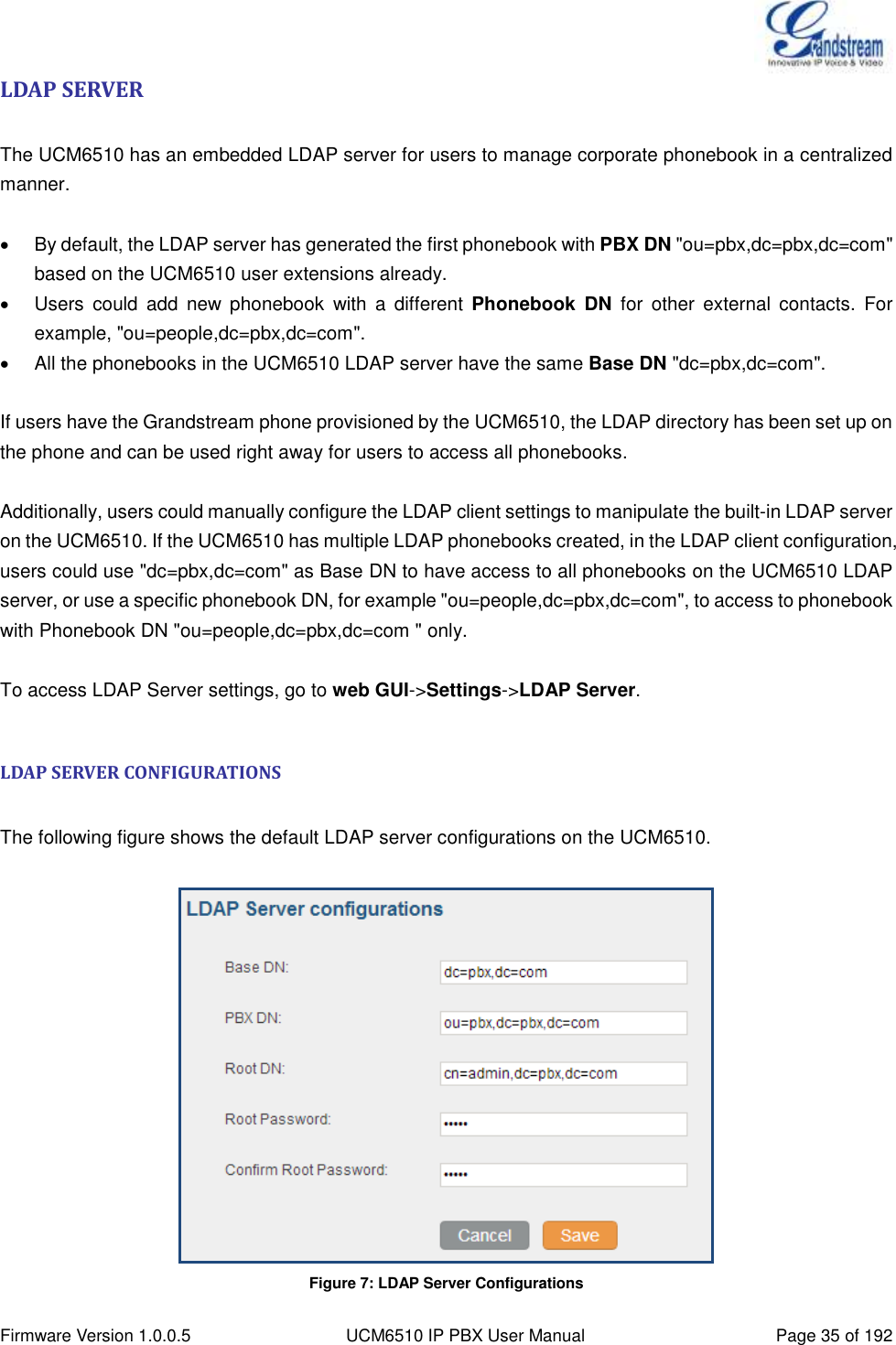
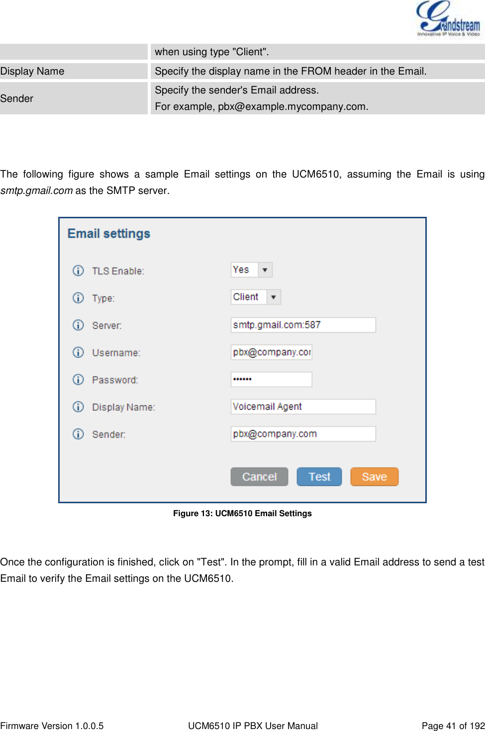
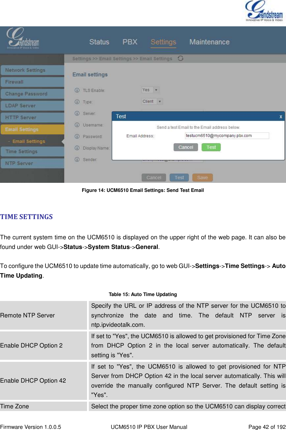
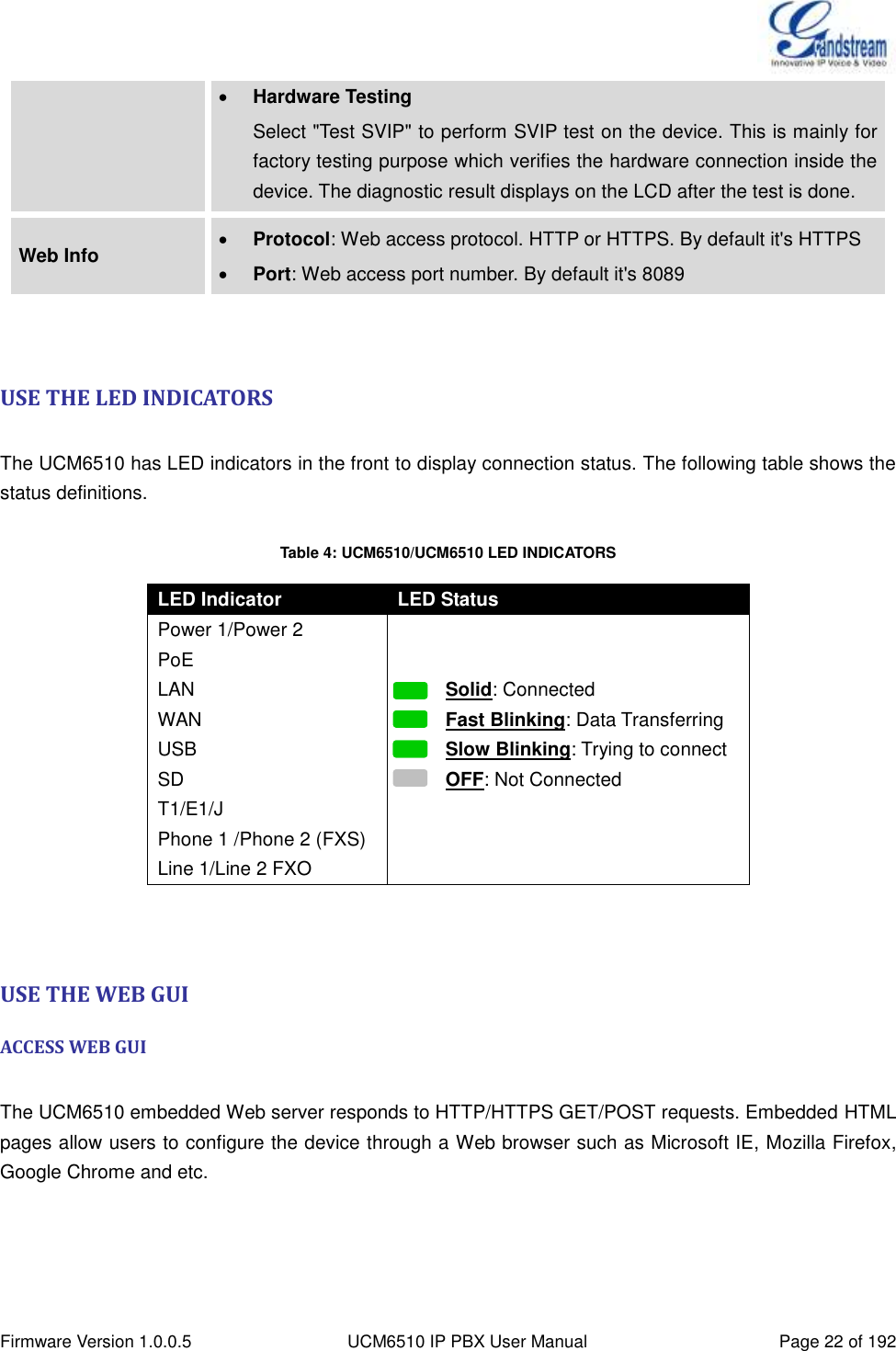
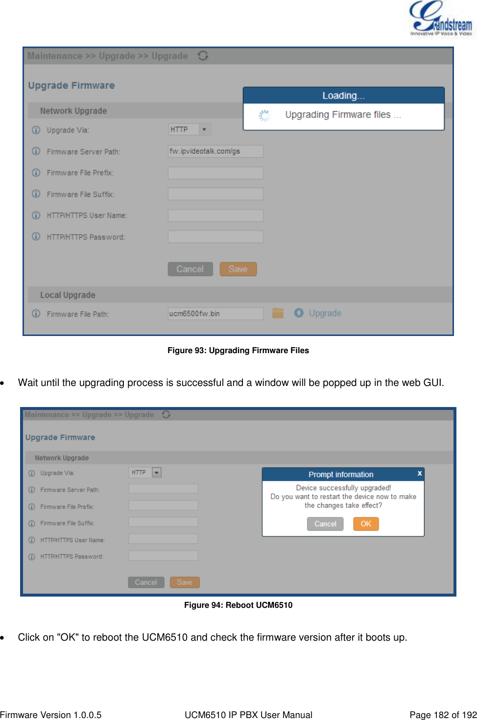
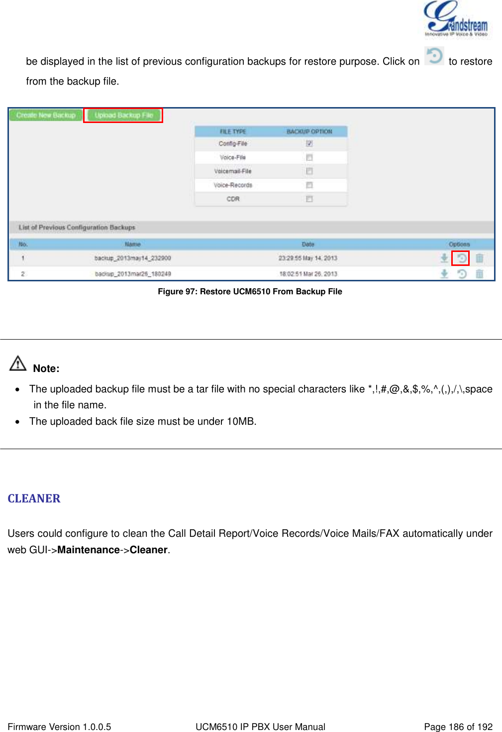
![Firmware Version 1.0.0.5 UCM6510 IP PBX User Manual Page 43 of 192 time accordingly. If "Self-Defined Tome Zone" is selected, please specify the time zone parameters in "Self-Defined Time Zone" field as described in below option. Self-Defined Time Zone If "Self-Defined Time Zone" is selected in "Time Zone" option, users will need define their own time zone following the format below. The syntax is: std offset dst [offset], start [/time], end [/time] Default is set to: MTZ+6MDT+5,M4.1.0,M11.1.0 MTZ+6MDT+5 This indicates a time zone with 6 hours offset and 1 hour ahead for DST, which is U.S central time. If it is positive (+), the local time zone is west of the Prime Meridian (A.K.A: International or Greenwich Meridian); If it is negative (-), the local time zone is east. M4.1.0,M11.1.0 The 1st number indicates Month: 1, 2, 3..., 12 (for Jan, Feb, .., Dec). The 2nd number indicates the nth iteration of the weekday: (1st Sunday, 3rd Tuesday…). Normally 1, 2, 3, 4 are used. If 5 is used, it means the last iteration of the weekday. The 3rd number indicates weekday: 0,1,2,..,6 ( for Sun, Mon, Tues, ... ,Sat). Therefore, this example is the DST which starts from the First Sunday of April to the 1st Sunday of November. To manually set the time on the UCM6510, go to web GUI->Settings->Time Settings->Set Time Manually. The format is YYYY-MM-DD HH:MI:SS. Figure 15: Set Time Manually](https://usermanual.wiki/Grandstream-Networks/UCM6510.Users-Manual/User-Guide-2378753-Page-44.png)
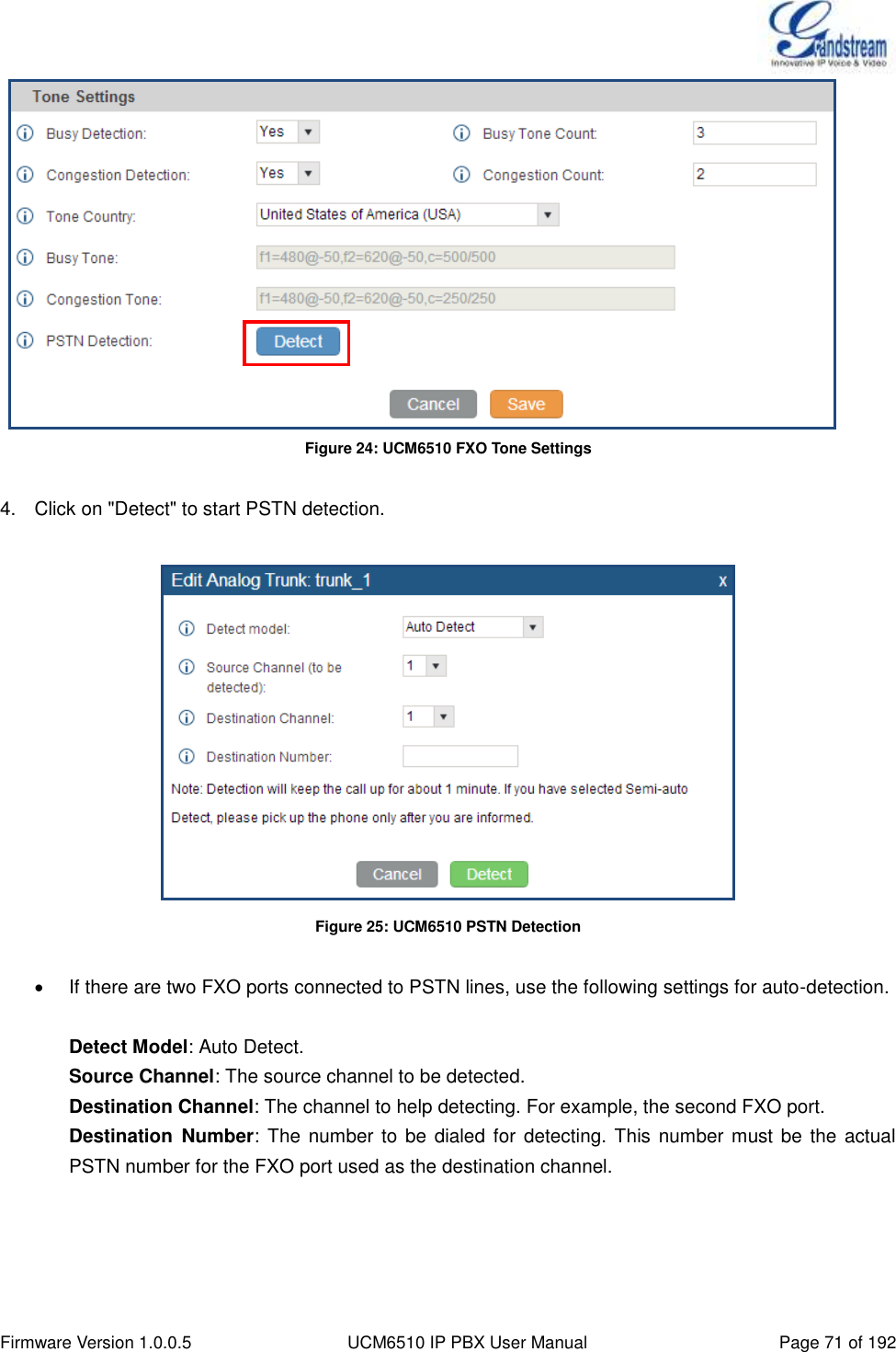
![Firmware Version 1.0.0.5 UCM6510 IP PBX User Manual Page 70 of 192 f1=val[@level][,f2=val[@level]],c=on1/off1[-on2/off2[-on3/off3]]; Frequencies are in Hz and cadence on and off are in ms. Frequencies Range: [0, 4000) Busy Level Range: (-300, 0) Cadence Range: [0, 16383]. Select Tone Country "Custom" to manually configure Busy Tone value. Default value: f1=480@-50,f2=620@-50,c=500/500 Congestion Tone Syntax: f1=val[@level][,f2=val[@level]],c=on1/off1[-on2/off2[-on3/off3]]; Frequencies are in Hz and cadence on and off are in ms. Frequencies Range: [0, 4000) Busy Level Range: (-300, 0) Cadence Range: [0, 16383]. Select Tone Country "Custom" to manually configure Busy Tone value. Default value: f1=480@-50,f2=620@-50,c=250/250 PSTN Detection Click on "Detect" to detect the busy tone, Polarity Reversal and Current Disconnect by PSTN. Before the detecting, please make sure there are more than one channel configured and working properly. If the detection has busy tone, the "Tone Country" option will be set as "Custom". PSTN DETECTION The UCM6510 provides PSTN detection function to help users detect the busy tone, Polarity Reversal and Current Disconnect by making a call from the PSTN line to another destination. The detecting call will be answered and up for about 1 minute. Once done, the detecting result will show and can be used for the UCM6510 settings. 1. Go to UCM6510 web GUI->PBX->Basic/Call Routes->Analog Trunks page. 2. Click to edit the analog trunk created for the FXO port. 3. In the dialog window to edit the analog trunk, go to "Tone Settings" section and there are two methods to set the busy tone. Tone Country. The default setting is "United States of America (USA)". PSTN Detection.](https://usermanual.wiki/Grandstream-Networks/UCM6510.Users-Manual/User-Guide-2378753-Page-71.png)
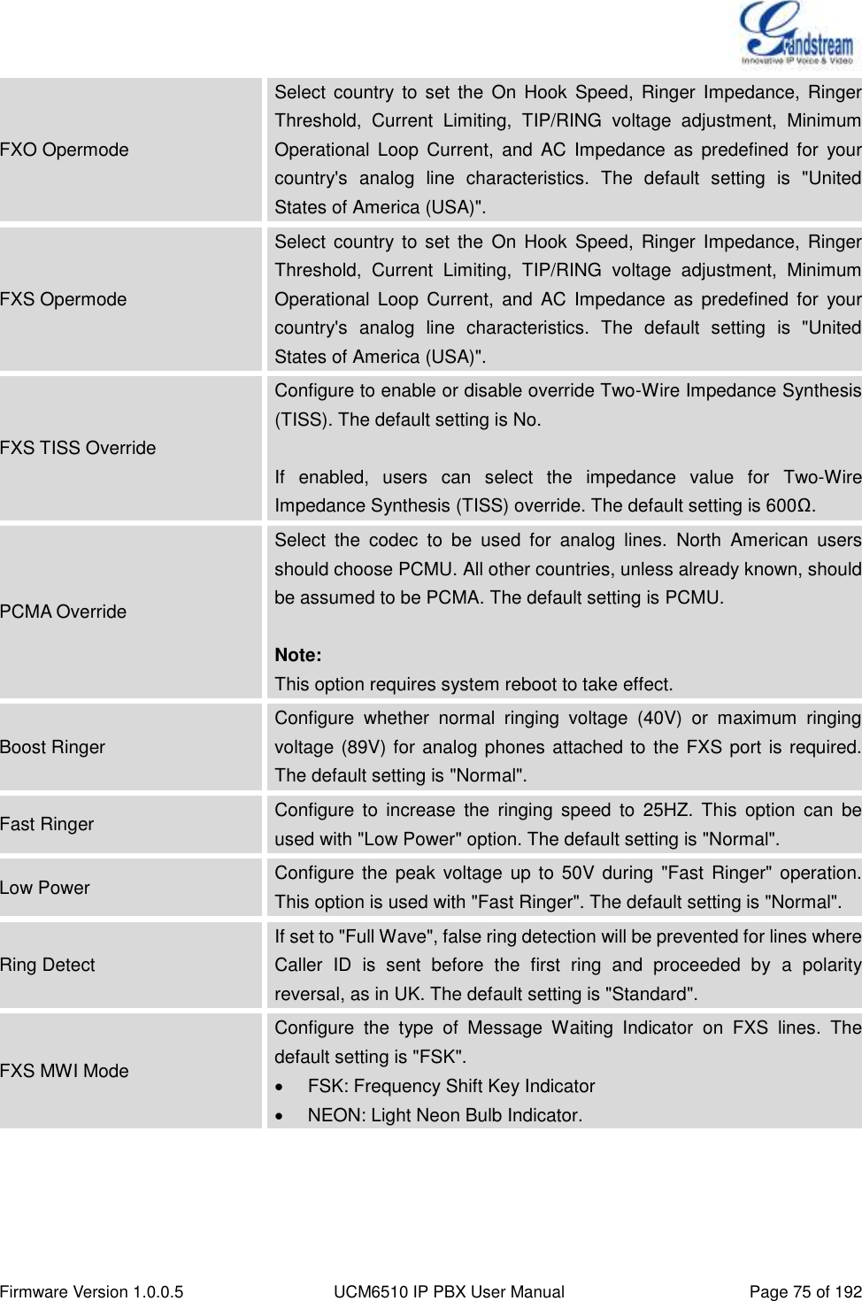
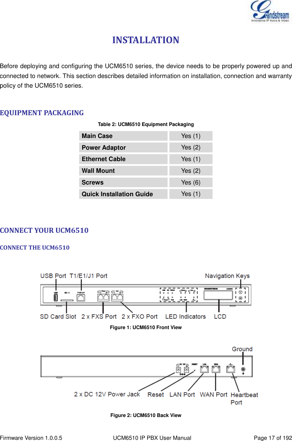
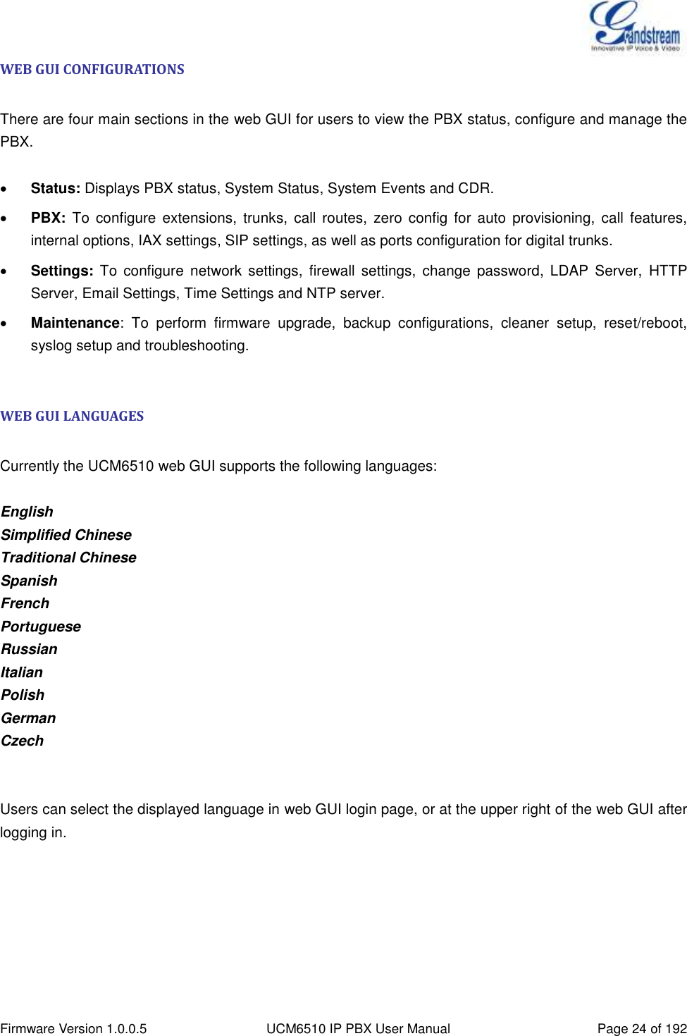
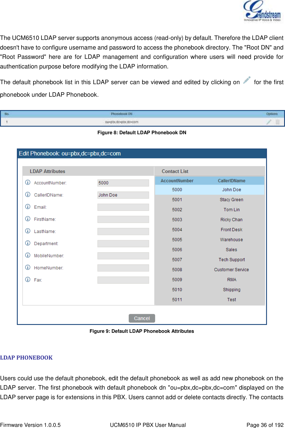
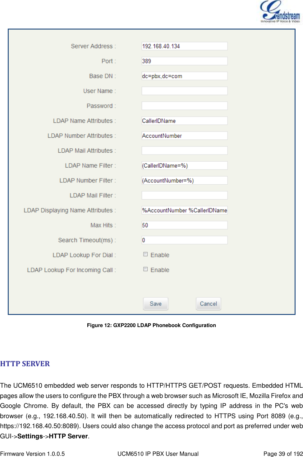
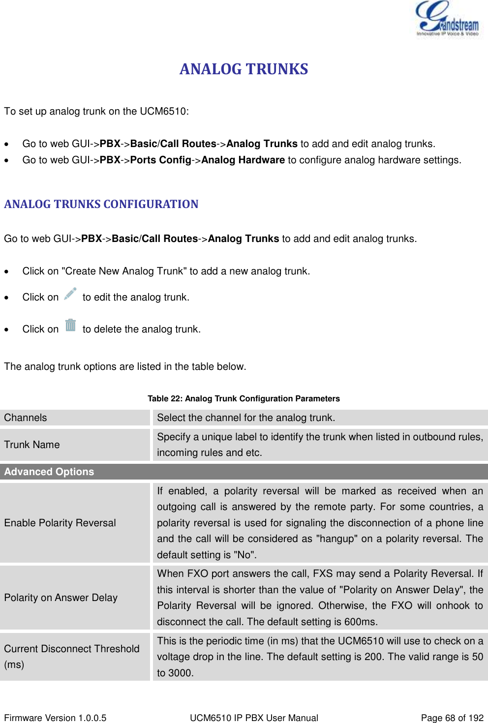
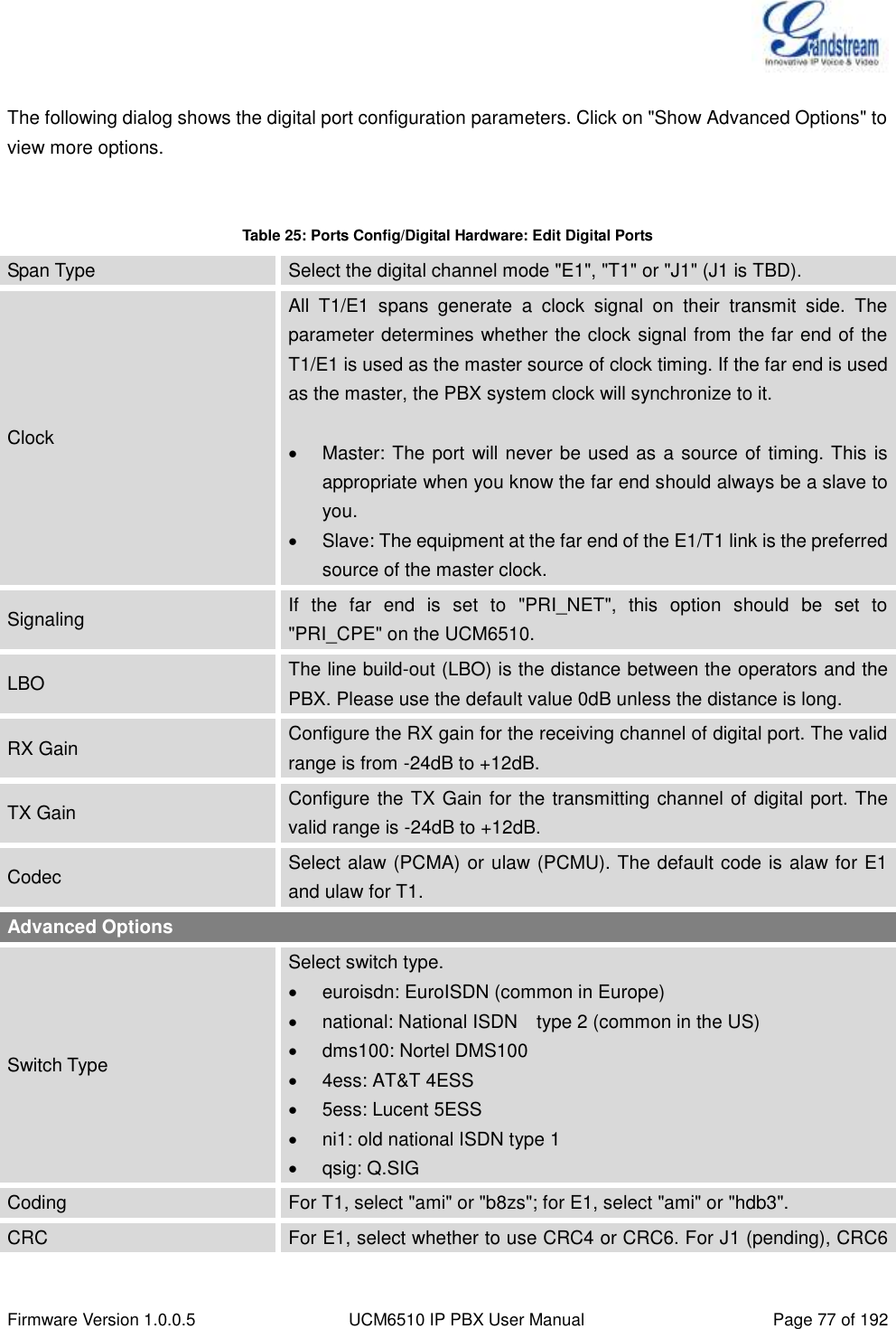
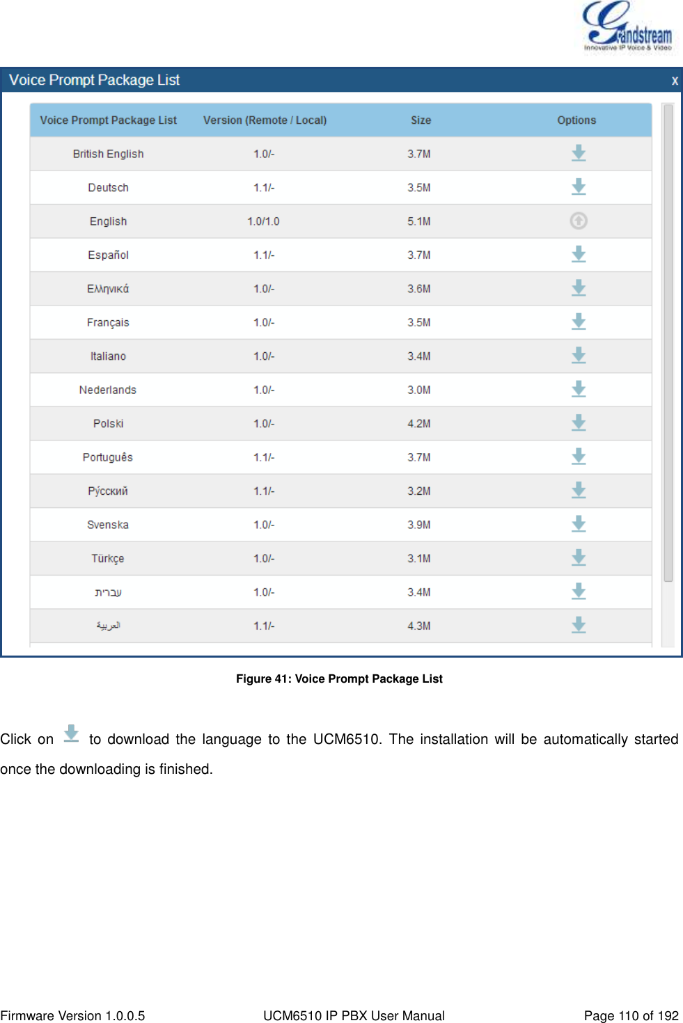
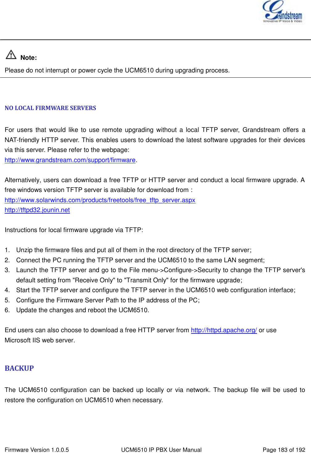
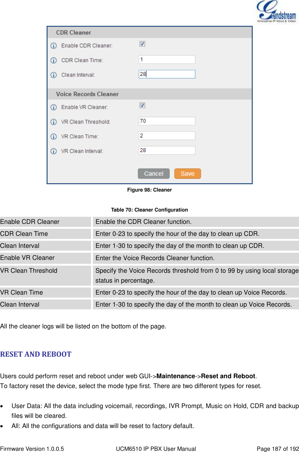
![Firmware Version 1.0.0.5 UCM6510 IP PBX User Manual Page 76 of 192 DIGITAL TRUNKS The UCM6510 supports E1/T1 which are physical connection technology used in digital network. T1 is the North American format whereas E1 is the European format with different transmission speed. Currently PRI signaling is supported for the E1/T1 interface on the UCM6510. To set up digital trunk on the UCM6510: Go to web GUI->PBX->Ports Config->Digital Hardware to configure port type and channels. Go to web GUI->PBX->Basic/Call Routes->Digital Trunks to add and edit digit trunks. DIGITAL HARDWARE CONFIGURATION Go to web GUI->PBX->Ports Config->Digital Hardware page and configure the following: Figure 30: Digital Hardware Configuration Step 1: Click on to edit digital ports. Please see configuration parameters in [Table 25: Ports Config/Digital Hardware: Edit Digital Ports]. Step 2: Click on to edit group. This assigns channels to be used for the digital port. For E1, 30 B channels can be assigned to the default group; for T1, 23 B channels can be assigned to the default group. Step 3: If fewer than 30 B channels for E1 or 23 B channels for T1 assigned in default group, users can click on to add more groups. This is not necessary in most cases and only default group is needed.](https://usermanual.wiki/Grandstream-Networks/UCM6510.Users-Manual/User-Guide-2378753-Page-77.png)
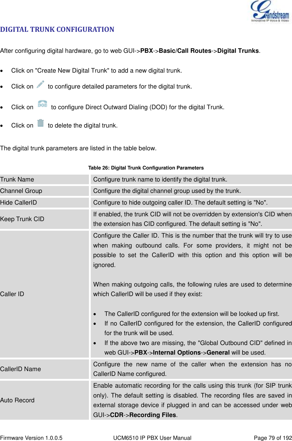
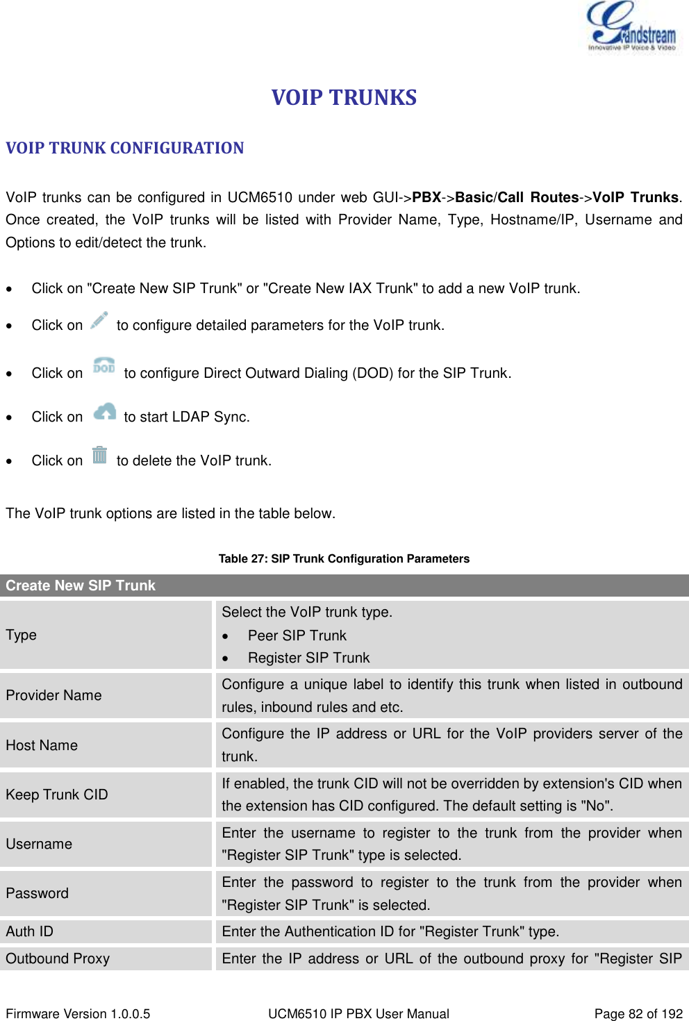
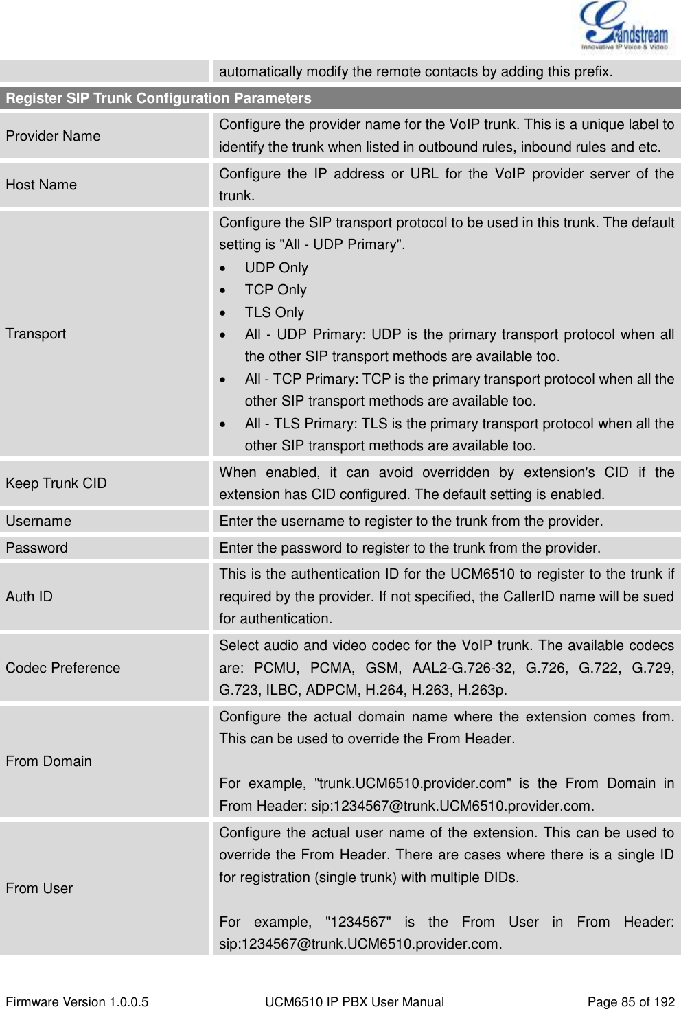
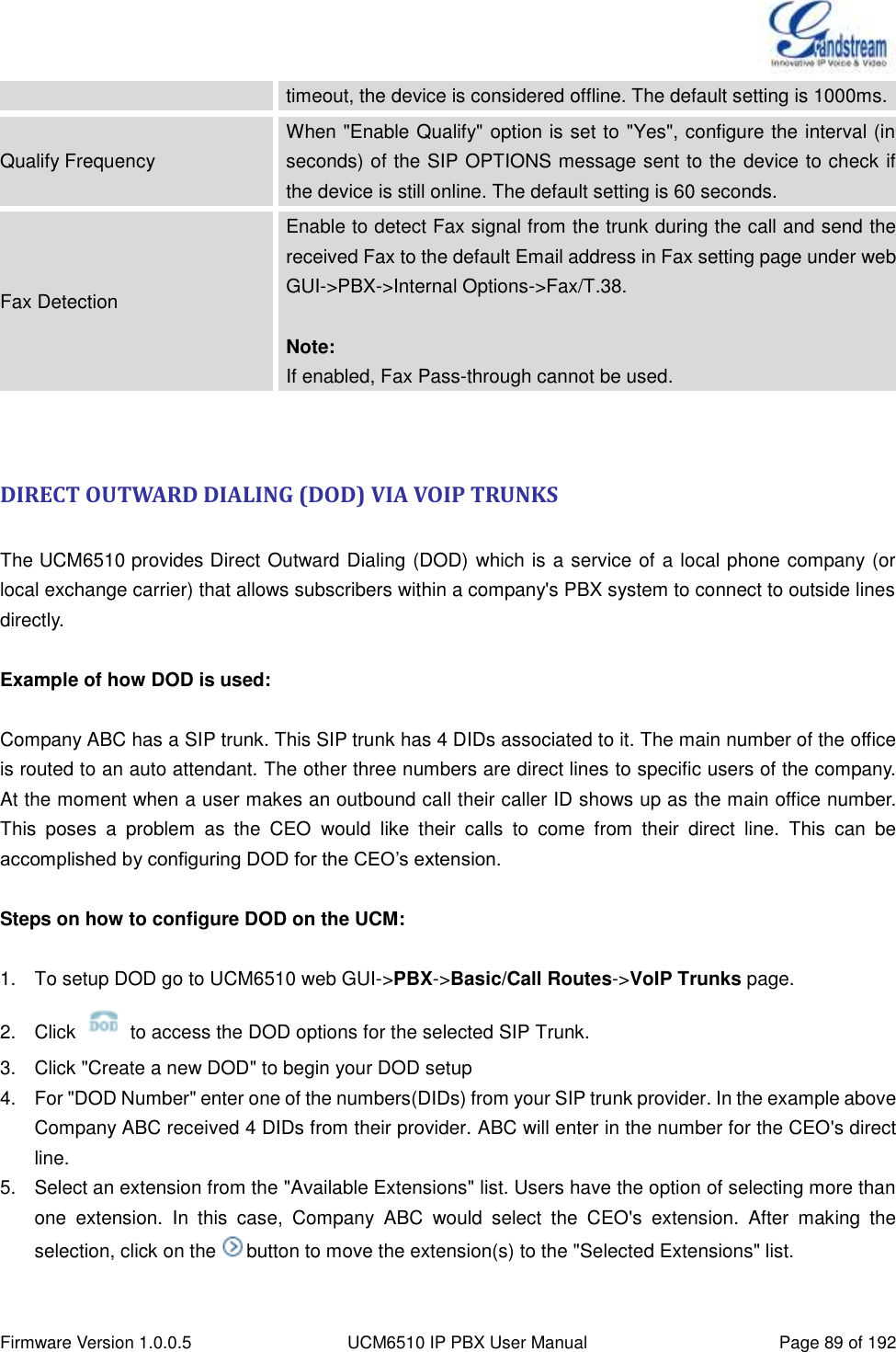
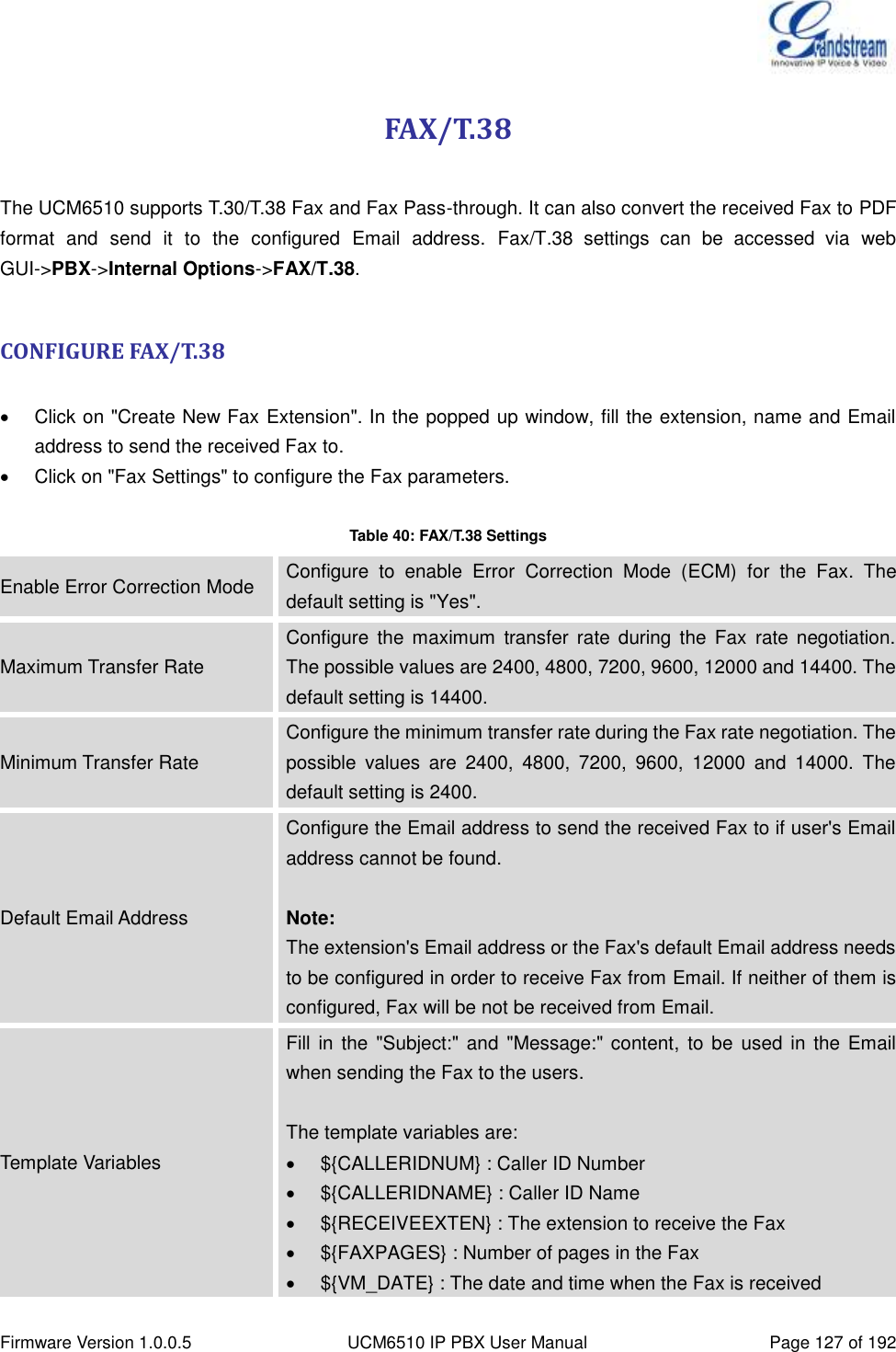
![Firmware Version 1.0.0.5 UCM6510 IP PBX User Manual Page 80 of 192 Fax Detection Enable to detect Fax signal from the trunk during the call and send the received Fax to the default Email address in Fax setting page under web GUI->PBX->Internal Options->Fax/T.38. Note: If enabled, Fax Pass-through cannot be used. DIRECT OUTWARD DIALING (DOD) VIA DIGITAL TRUNKS Please refer to section [DIRECT OUTWARD DIALING (DOD) VIA VOIP TRUNKS]. DIGITAL TRUNK TROUBLESHOOTING After configuring the digital trunk on the UCM6510 as described above, if it doesn't work as expected, go to web GUI->Maintenance->Troubleshooting->PRI Signaling Trace to capture a trace for the T1/E1 interface. The users can take a look at the trace for basic analysis or contact Grandstream Technical support in the following link for further assistance if the issue is not resolved. http://www.grandstream.com/index.php/support Figure 31: Troubleshooting Digital Trunks](https://usermanual.wiki/Grandstream-Networks/UCM6510.Users-Manual/User-Guide-2378753-Page-81.png)
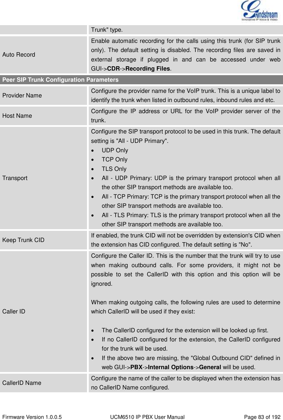
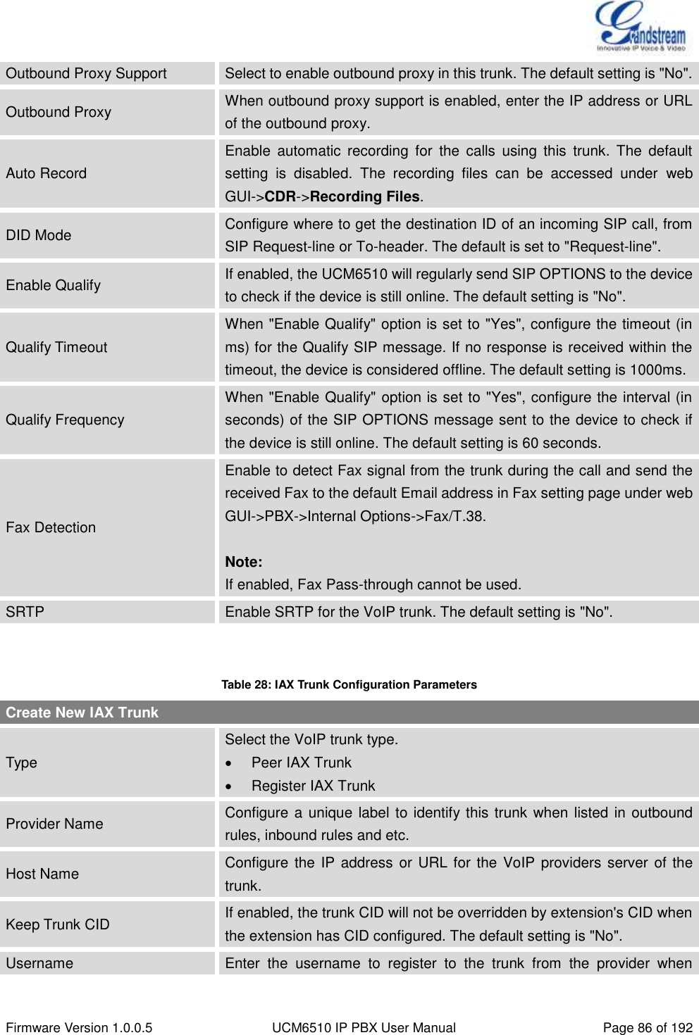
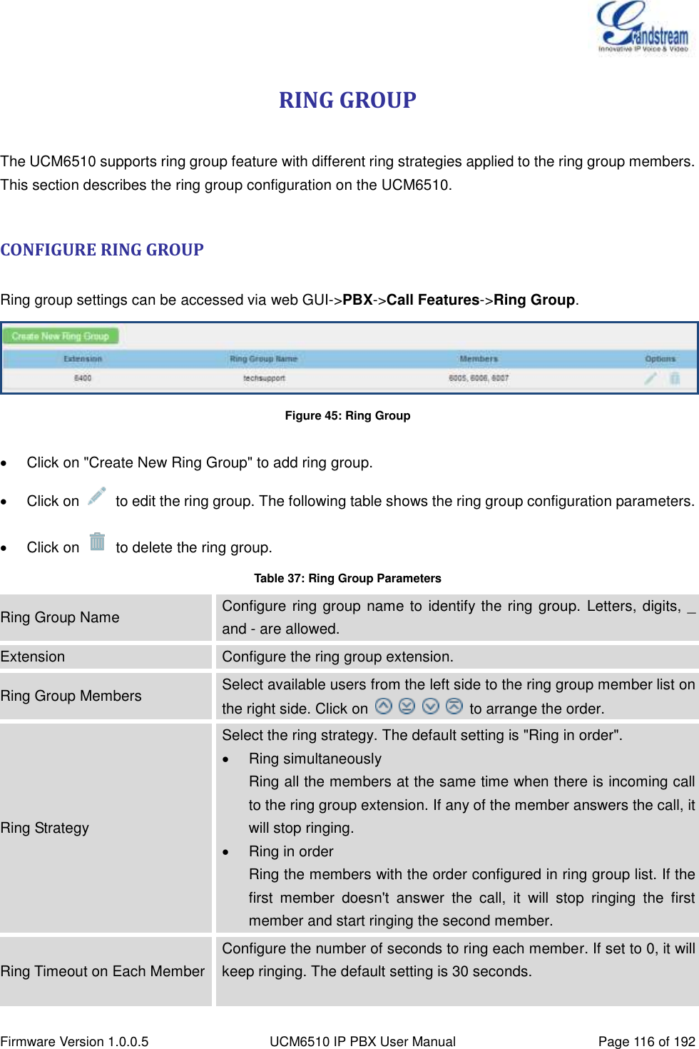
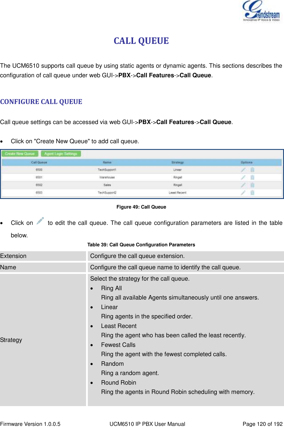
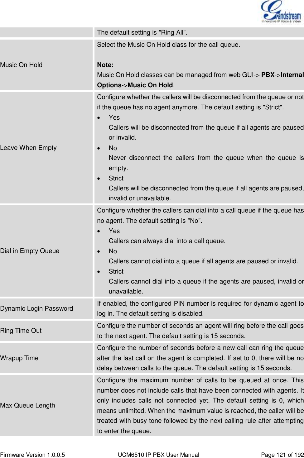
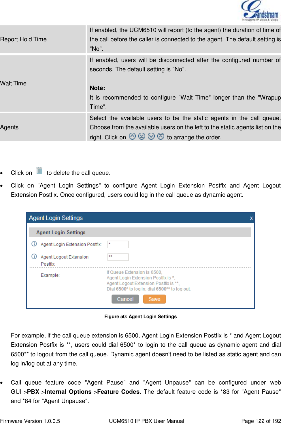
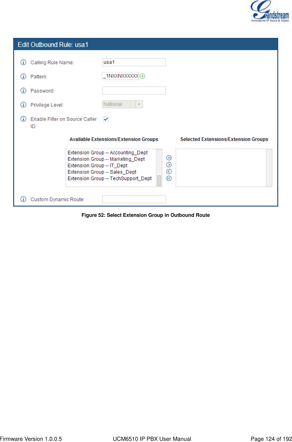
![Firmware Version 1.0.0.5 UCM6510 IP PBX User Manual Page 91 of 192 CALL ROUTES OUTBOUND ROUTES In the UCM6510, an outgoing calling rule pairs an extension pattern with a trunk used to dial the pattern. This allows different patterns to be dialed through different trunks (e.g., "Local" 7-digit dials through a FXO while "Long distance" 10-digit dials through a low-cost SIP trunk). Users can also set up a failover trunk to be used when the primary trunk fails. Go to web GUI->PBX->Basic/Call Routes->Outbound Routes to add and edit outbound rules. Click on "Create New Outbound Rule" to add a new outbound route. Click on to edit the outbound route. Click on to delete the outbound route. Click on to move the outbound route up/down to arrange the priority of the outbound rule. The outbound rule listed on the top has higher priority. When the dialing pattern matches two or more outbound rules (for example, the same pattern is configured for 2 different trunks; or dialing out 1000 matches pattern 1xxx for trunk 1 and pattern 100x for trunk 2), the one listed on the top will be used. Table 29: Outbound Route Configuration Parameters Calling Rule Name Configure the name of the calling rule (e.g., local, long_distance, and etc). Letters, digits, _ and - are allowed. Pattern All patterns are prefixed with the "_". Special characters: X: Any Digit from 0-9. Z: Any Digit from 1-9. N: Any Digit from 2-9. ".": Wildcard. Match one or more characters. "!": Wildcard. Match zero or more characters immediately. Example: [12345-9] - Any digit from 1 to 9. Password Configure the password for users to use this rule when making outbound calls. Privilege Level Select privilege level for the outbound rule. Internal: The lowest level required. All users can use this rule. Local: Users with Local, National, or International level are allowed](https://usermanual.wiki/Grandstream-Networks/UCM6510.Users-Manual/User-Guide-2378753-Page-92.png)
![Firmware Version 1.0.0.5 UCM6510 IP PBX User Manual Page 92 of 192 to use this rule. National: Users with National or International level are allowed to use this rule. International: The highest level required. Only users with international level can use this rule. The default setting is "International". Please be aware of the potential security risks when using "Internal" level, which means all users can use this outbound rule to dial out from the trunk. Enable Filter on Source Caller ID When enabled, users could specify extensions allowed to use this outbound route. "Privilege Level" is automatically disabled if using "Enable Filter on Source Caller ID". The following two methods can be used at the same time to define the extensions as the source caller ID. 1. Select available extensions from the left to the right. This allows users to specify arbitrary single extensions. 2. Custom Dynamic Route: define the pattern for the source caller ID. This allows users to define extension range instead of selecting them one by one. All patterns are prefixed with the "_". Special characters: X: Any Digit from 0-9. Z: Any Digit from 1-9. N: Any Digit from 2-9. ".": Wildcard. Match one or more characters. "!": Wildcard. Match zero or more characters immediately. Example: [12345-9] - Any digit from 1 to 9. Send This Call Through Trunk Use Trunk Select the trunk for this outbound rule. Strip Allows the user to specify the number of digits that will be stripped from the beginning of the dialed string before the call is placed via the selected trunk. Example: The users will dial 9 as the first digit of a long distance calls. However, 9 should not be sent out via analog lines and the PSTN line. In this case, 1 digit should be stripped before the call is placed.](https://usermanual.wiki/Grandstream-Networks/UCM6510.Users-Manual/User-Guide-2378753-Page-93.png)
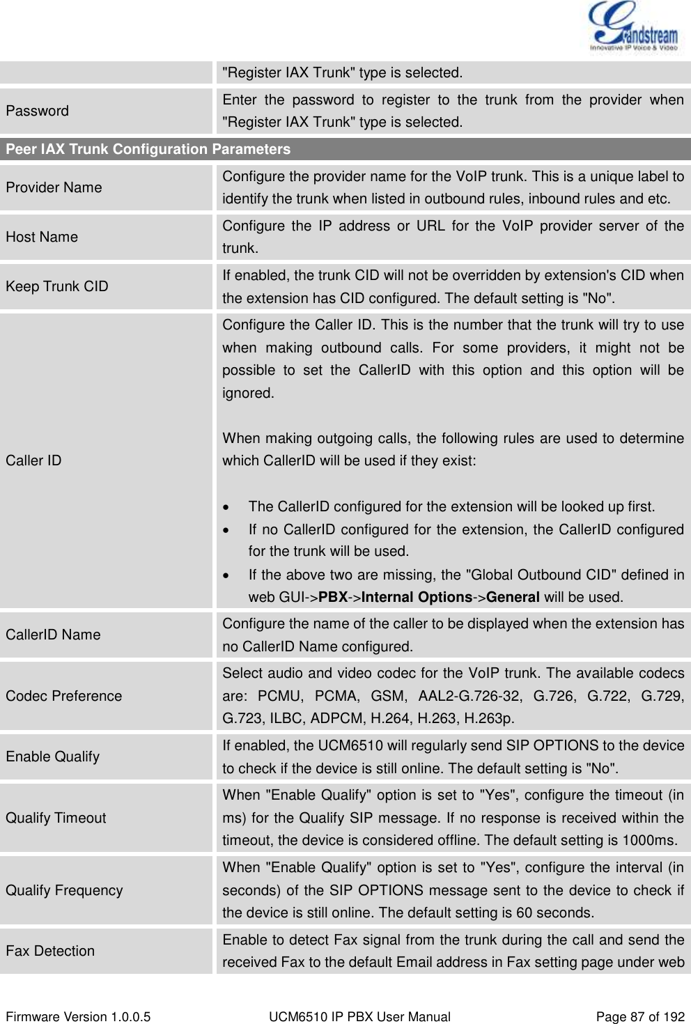
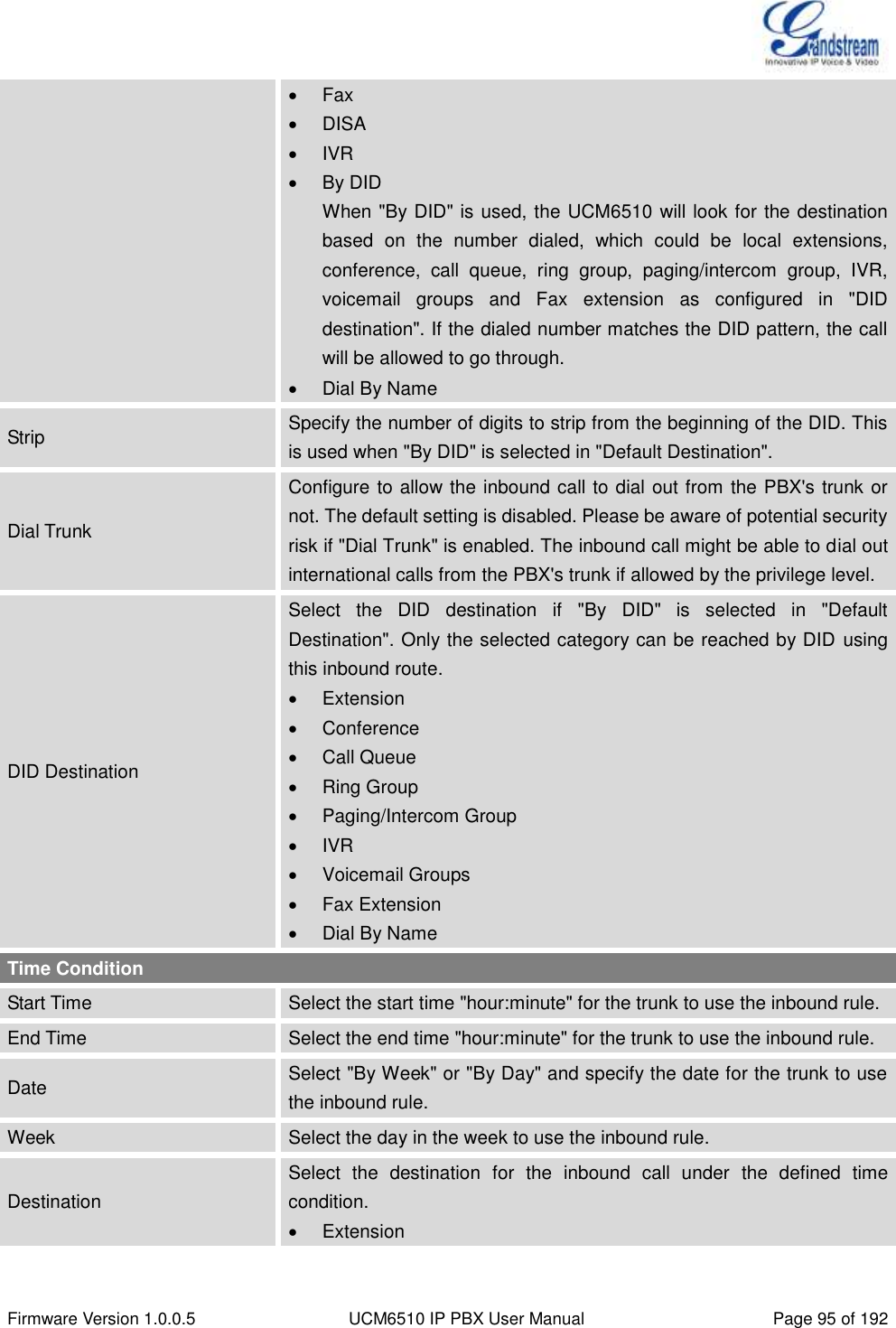
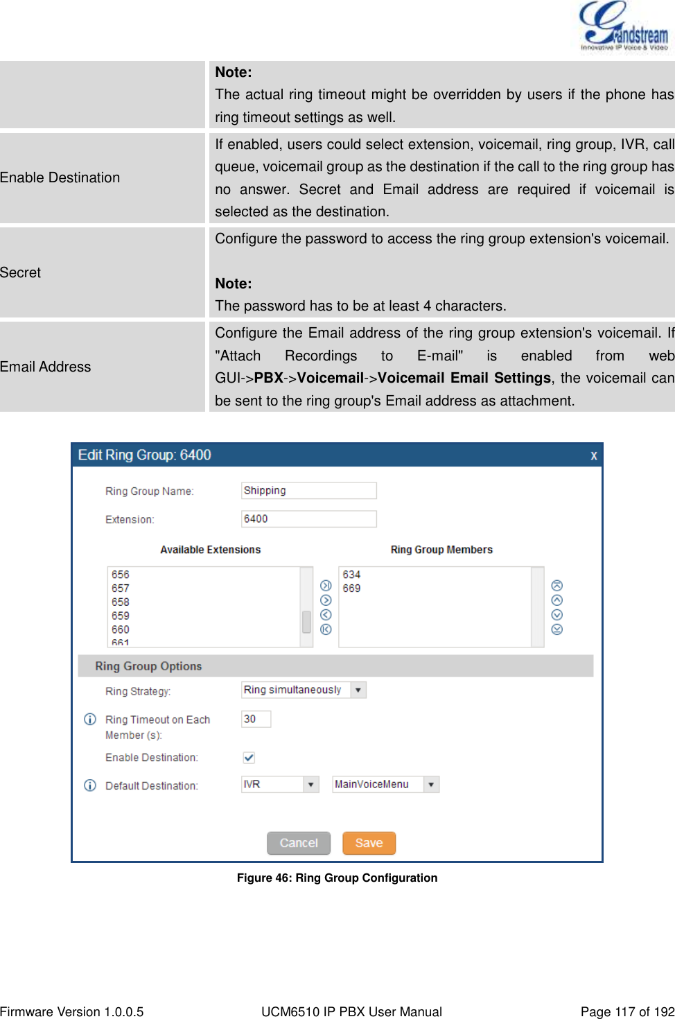
![Firmware Version 1.0.0.5 UCM6510 IP PBX User Manual Page 94 of 192 INBOUND RULE CONFIGURATIONS Table 30: Inbound Rule Configuration Parameters Trunks Select the trunk to configure the inbound rule. DID Pattern All patterns are prefixed with the "_". Special characters: X: Any Digit from 0-9. Z: Any Digit from 1-9. N: Any Digit from 2-9. ".": Wildcard. Match one or more characters. "!": Wildcard. Match zero or more characters immediately. Example: [12345-9] - Any digit from 1 to 9. The pattern can be composed of two parts, divided by a ‘/’ character. The first part is used to specify the dialed number the second part is used to specify the caller ID and it is optional, if set it means only the extension with the specific caller ID is allowed to call in or call out. For example, patter '_2XXX/1234' means the only extension with the caller ID '1234' is allowed to use this rule. Privilege Level Select privilege level for the inbound rule when a VoIP trunk is selected in "Trunks" field. Internal: The lowest level required. All users can use this rule. Local: Users with Local, National or International level are allowed to use this rule. National: Users with National or International level are allowed to use this rule. International: The highest level required. Only users with international level can use this rule. This setting is used to compared with the outbound trunk's permission level when the inbound call dials out via a trunk on the UCM6510. Therefore, it's usually used only when the "Default Destination" is set to "By DID". Default Destination Select the default destination for the inbound call. Extension Voicemail Conference Room Call Queue Ring Group Paging/Intercom Voicemail Group](https://usermanual.wiki/Grandstream-Networks/UCM6510.Users-Manual/User-Guide-2378753-Page-95.png)
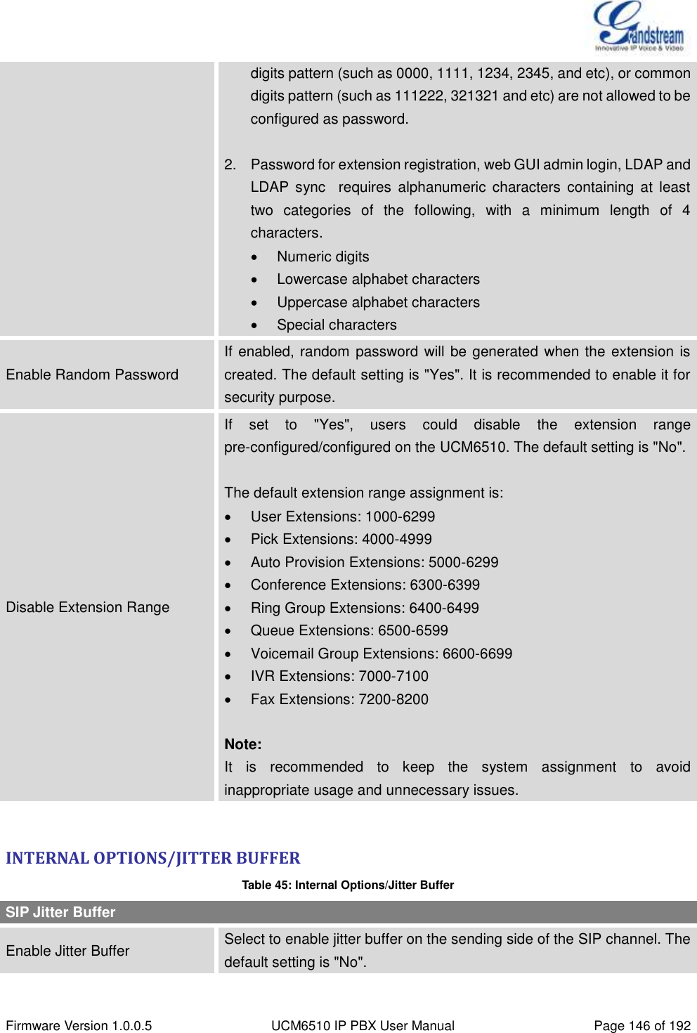
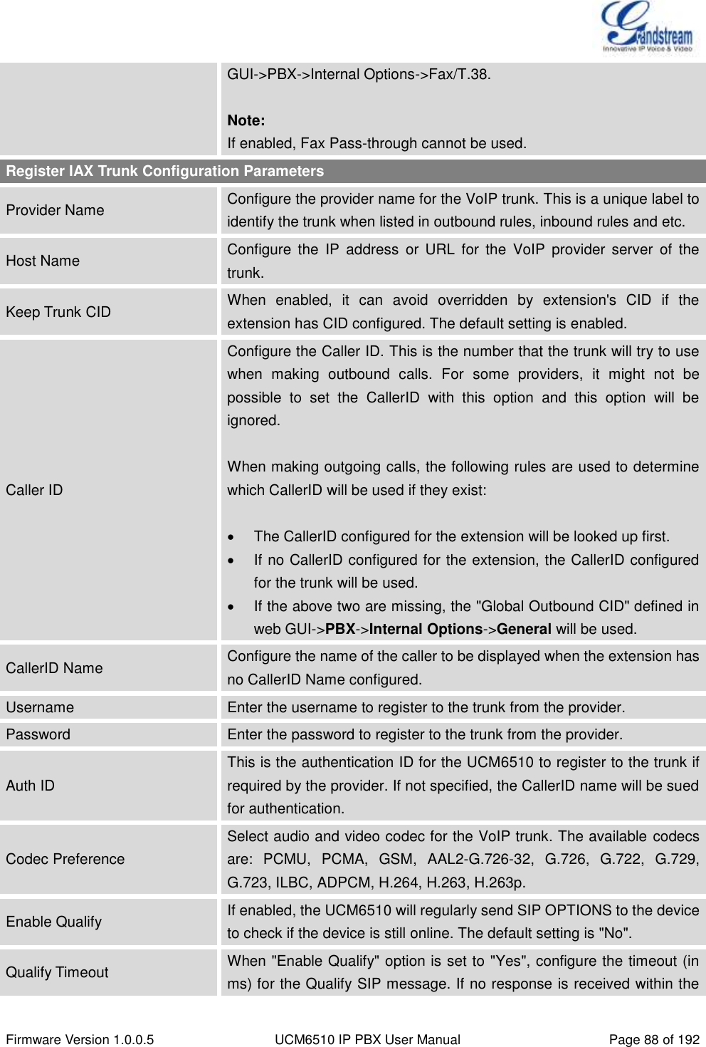
![Firmware Version 1.0.0.5 UCM6510 IP PBX User Manual Page 147 of 192 Jitter Buffer Size Configure the time (in ms) to buffer. This is the jitter buffer size used in "Fixed" jitter buffer, or used as the initial time for "adaptive" jitter buffer. The default setting is 100. Max Jitter Buffer Configure the maximum time (in ms) to buffer for "Adaptive" jitter buffer implementation, or used as the jitter buffer size for "Fixed" jitter buffer implementation. The default setting is 200. Implementation Configure the jitter buffer implementation on the sending side of a SIP channel. The default setting is "Fixed". Fixed The size is always equal to the value of "Max Jitter Buffer". Adaptive The size is adjusted automatically and the maximum value equals to the value of "Max Jitter Buffer". INTERNAL OPTIONS/RTP SETTINGS Table 46: Internal Options/RTP Settings RTP Start Configure the RTP port starting number. The default setting is 10000. RTP End Configure the RTP port ending address. The default setting is 20000. Strict RTP Configure to enable or disable strict RTP protection. If enabled, RTP packets that do not come from the source of the RTP stream will be dropped. The default setting is "Disable". RTP Checksums Configure to enable or disable RTP Checksums on RTP traffic. The default setting is "Disable". INTERNAL OPTIONS/STUN MONITOR Table 47: Internal Options/STUN Monitor STUN Server Configures the IP address or URL of the STUN server to query. If not specified, STUN is disabled. The default setting is stun.ipvideotalk.com. Valid format: [(hostname | IP-address) [':' port] The default port number is 3478 if not specified. STUN Refresh Configure the number of seconds between STUN Refreshes. The default setting is 30 seconds.](https://usermanual.wiki/Grandstream-Networks/UCM6510.Users-Manual/User-Guide-2378753-Page-148.png)
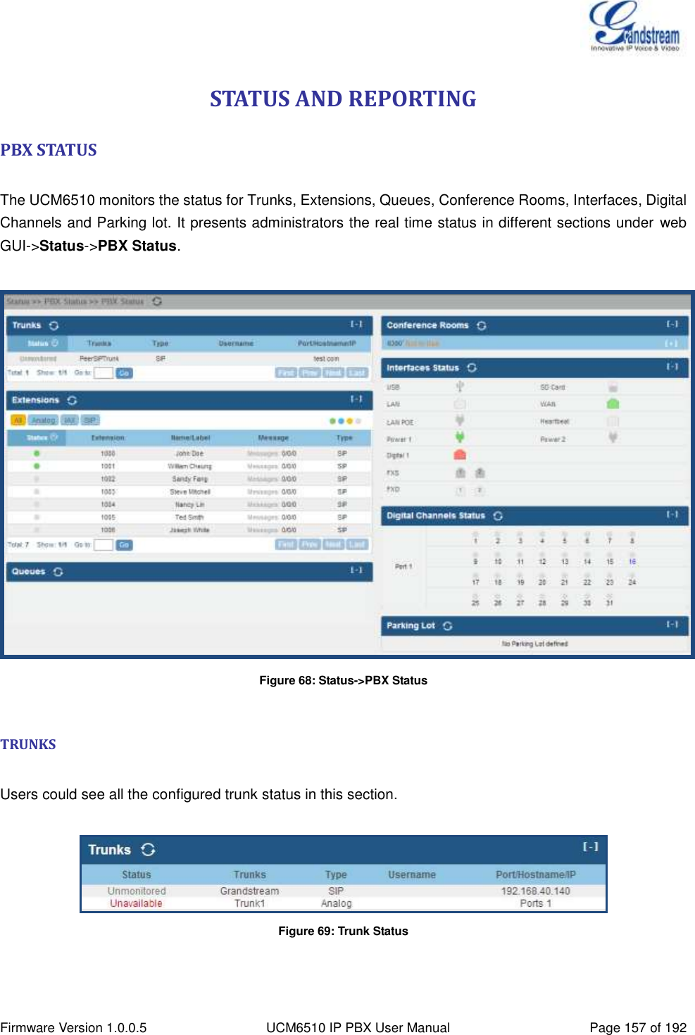
![Firmware Version 1.0.0.5 UCM6510 IP PBX User Manual Page 158 of 192 Table 57: Trunk Status Status Display trunk status. Analog trunk/Digital trunk status: Available Busy Unavailable Unknown Error SIP Peer trunk status: Unreachable: The hostname cannot be reached. Unmonitored: QUALIFY feature is not turned on to be monitored. Reachable: The hostname can be reached. SIP Register trunk status: Registered Unrecognized Trunk Trunks Display trunk name Type Display trunk Type: Analog E1/T1 SIP IAX Username Display username for this trunk. Port/Hostname/IP Display Port for analog trunk, or Hostname/IP for VoIP (SIP/IAX) trunk. Other operations are also available in trunk status section: Click on "Trunks", the web page will redirect to trunk configuration page which can also be accessed via web GUI->PBX->Basic/Call Routes->Analog Trunks. Click on to refresh the trunk status. Click on [ + ] to expand the status detail table. Click on [ - ] to hide the status detail table. EXTENSIONS Users could see all the configured extension status in this section.](https://usermanual.wiki/Grandstream-Networks/UCM6510.Users-Manual/User-Guide-2378753-Page-159.png)
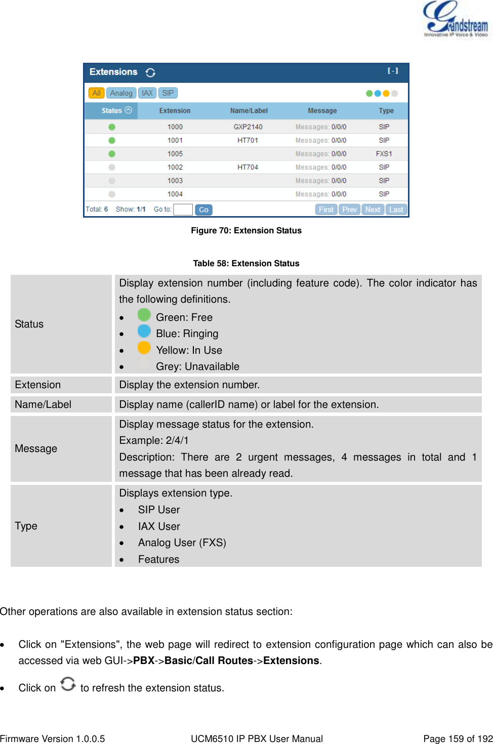
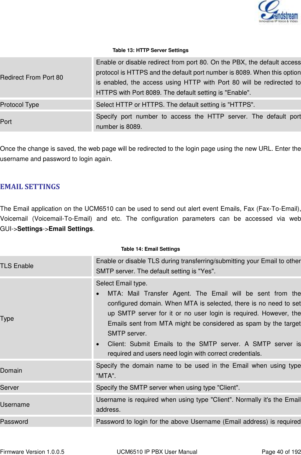
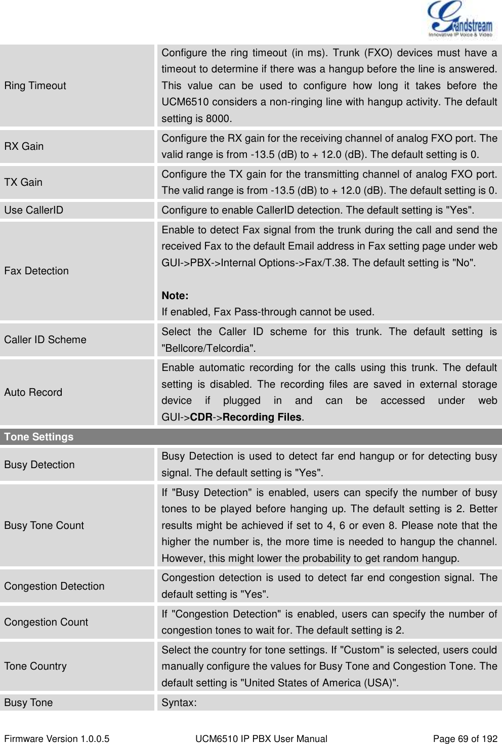
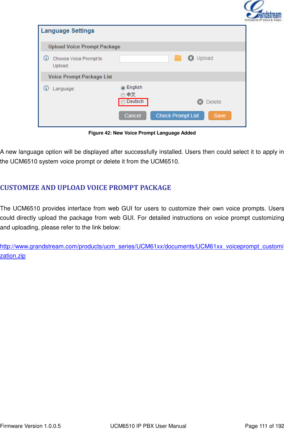
![Firmware Version 1.0.0.5 UCM6510 IP PBX User Manual Page 160 of 192 Click on one of the tabs to display the corresponding extensions accordingly. Click on [ + ] to expand the status detail table. Click on [ - ] to hide the status detail table. QUEUES Users could see all the configured call queue status in this section. The following figure shows the call queue 6500 being in used. Figure 71: Queue Status The current call status (caller ID, duration), agent status, service level, calls summary (completed/abandoned) are shown for the call queue. The agent status is defined as below. Table 59: Agent Status The agent is available/idle. The agent is ringing. The agent is talking/busy. The agent has been logged out. On the UCM6510, Service Level is defined as the percentage of high-quality calls over all calls in the call queue, where high-quality call means calls answered within 10 seconds. Other operations are also available in queue status section: Click on "Queues", the web page will redirect to call queue configuration page which can also be accessed via web GUI->PBX->Call Features->Call Queue. Click on to refresh the call queue status. Click on [ + ] to expand the call queue detail. Click on [ - ] to hide the call queue detail.](https://usermanual.wiki/Grandstream-Networks/UCM6510.Users-Manual/User-Guide-2378753-Page-161.png)
![Firmware Version 1.0.0.5 UCM6510 IP PBX User Manual Page 161 of 192 CONFERENCE ROOMS Users could see all the conference room status in this section. It shows all the configured conference rooms, current users, call duration for each user and conference call. Figure 72: Conference Room Status Other operations are also available in conference room status section: Click on "Conference Rooms", the web page will redirect to conference room configuration page which can also be accessed via web GUI->PBX->Call Features->Conference. Click on to refresh the conference room status. Click on [ + ] to expand the conference room details. Click on [ - ] to hide the conference room details. INTERFACES STATUS This section displays interface connection status on the UCM6510 for USB, SD Card, LAN, WAN, LAN PoE, Heartbeat, Power 1, Power 2, Digital, FXS and FXO ports. Table 60: Interface Status Indicators USB connected. USB disconnected. SD Card connected. SD Card disconnected. LAN/WAN/Heartbeat connected. LAN/WAN/Heartbeat not configured.](https://usermanual.wiki/Grandstream-Networks/UCM6510.Users-Manual/User-Guide-2378753-Page-162.png)
![Firmware Version 1.0.0.5 UCM6510 IP PBX User Manual Page 162 of 192 LAN/WAN/Heartbeat disconnected. FXS/FXO/Digital connected. FXS/FXO/Digital waiting. FXS/FXO/Digital busy. FXS/FXO/Digital not configured. FXS/FXO/Digital disconnected. Other operations are also available in interface status section: Click on to refresh the interface status. Click on [ + ] to expand the interface details. Click on [ - ] to hide the interface details. PARKING LOT The UCM6510 supports call park using feature code. When there is call being parked, this section will display the parking lot status. Figure 73: Parking Lot Status Table 61: Parking Lot Status Caller ID Display the caller ID who parks the call. Channel Display channel for the call park. Extension Display the parking lot number where the call is parked/retrieved. Timeout Display timeout (in seconds) for the parked call. The status page will dynamically update this timer from 120 seconds (default) to 0. When the timer reaches 0, the caller who parks the call will be called back. Other operations are also available in parking lot status section:](https://usermanual.wiki/Grandstream-Networks/UCM6510.Users-Manual/User-Guide-2378753-Page-163.png)
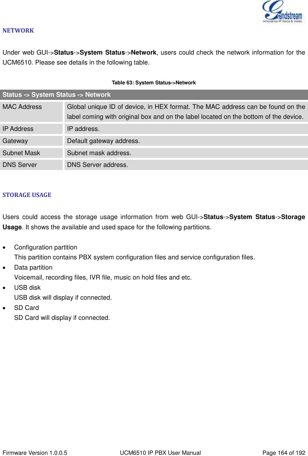
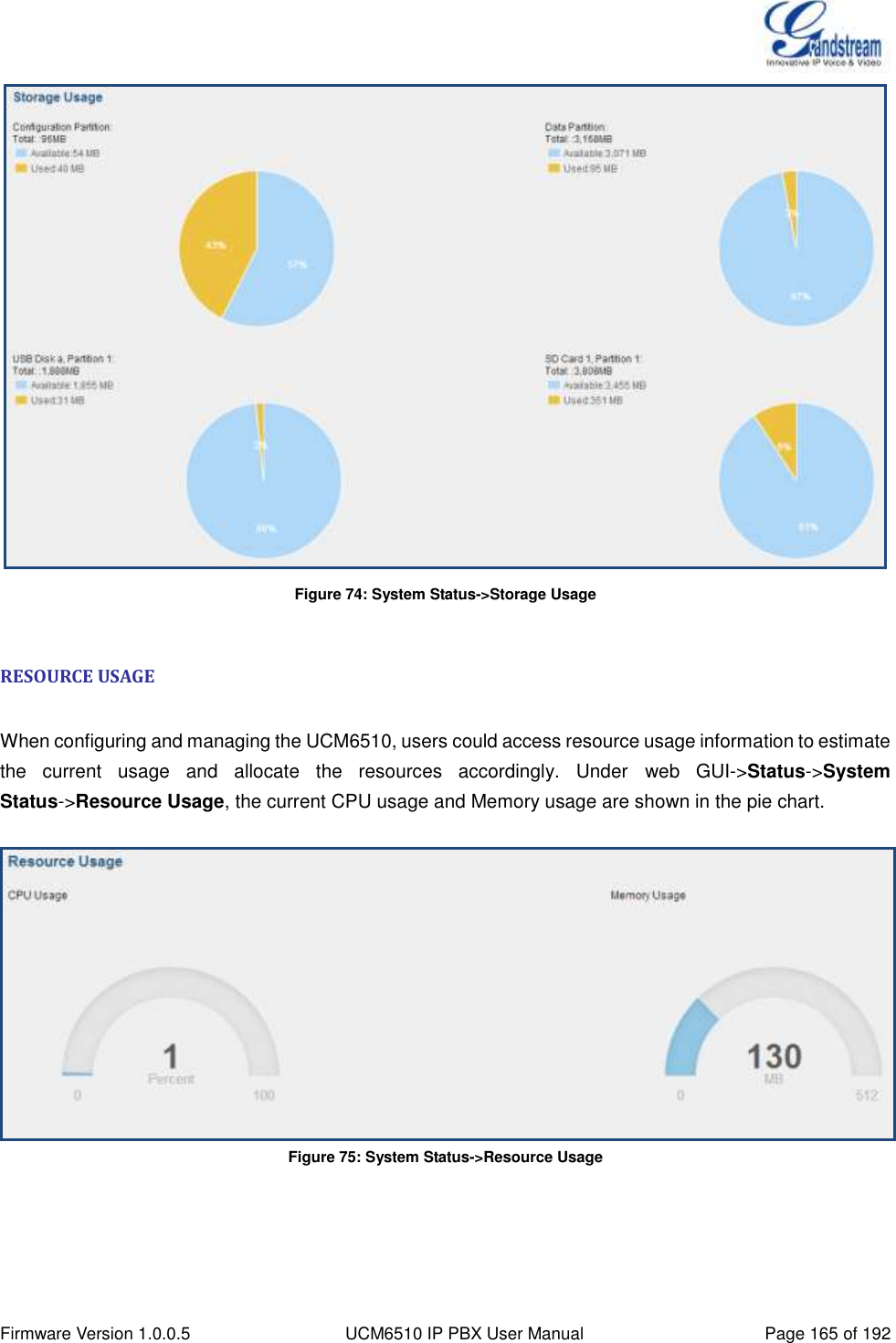
![Firmware Version 1.0.0.5 UCM6510 IP PBX User Manual Page 163 of 192 Click on "Parking Lot", the web page will redirect to feature codes page which can also be accessed via web GUI->PBX->Internal Options->Feature Codes. Click on to refresh the parking lot status. Click on [ + ] to expand the parking lot details. Click on [ - ] to hide the parking details. SYSTEM STATUS The UCM6510 system status can be accessed via web GUI->Status->System Status, which displays the following system information. General Network Storage Usage Resource Usage GENERAL Under web GUI->Status->System Status->General, users could check the hardware and software information for the UCM6510. Please see details in the following table. Table 62: System Status->General Status ->System Status -> General Model Product model. Part Number Product part number. System Time Current system time. The current system time is also available on the upper right of each web page. Up Time System up time since the last reboot. Idle Time System idle time since the last reboot. Boot Boot version. Core Core version. Base Base version. Program Program version. This is the main software release version. Recovery Recovery version.](https://usermanual.wiki/Grandstream-Networks/UCM6510.Users-Manual/User-Guide-2378753-Page-164.png)
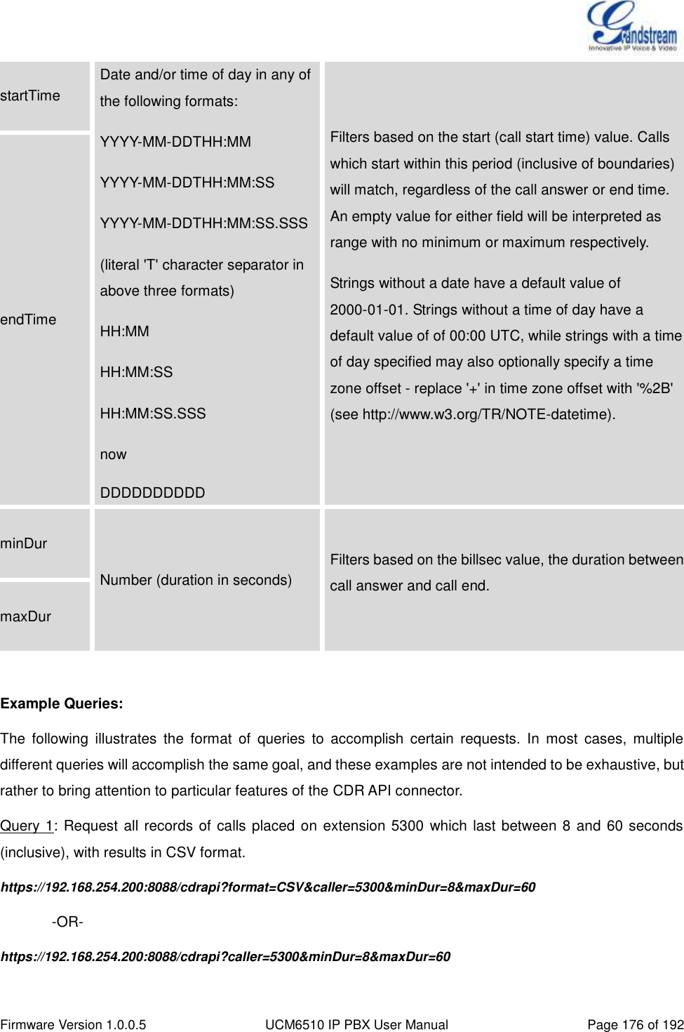
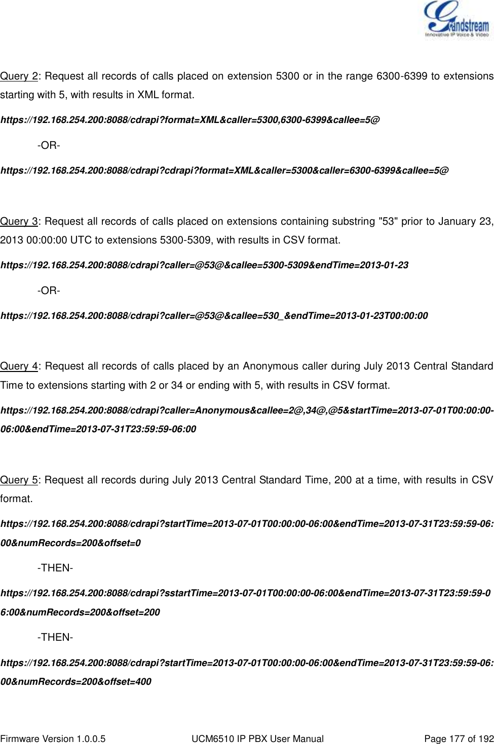
![Firmware Version 1.0.0.5 UCM6510 IP PBX User Manual Page 175 of 192 The format of the HTTPS request for the CDR API is as below. https://[UCM IP]:[Port]/cdrapi?[option1]=[value]&[option2]=[value]&... By default, the port number for the API is 8443. The options included in the request URI control the record matching and output format. For CDR matching parameters, all non-empty parameters must have a match to return a record. Parameters can appear in the URI in any order. Multiple values given for caller or callee will be concatenated. The following table shows the parameter list used in the CDR API. Table 67: CDR API URI Parameters Field Value Details format csv, xml, json Define the format for output of matching CDR rows. Default is csv (comma separated values). numRecords Number: 0-1000 Number of records to return. Default is 1000, which is also the maximum allowed value. offset Number Number of matching records to skip. This will be combined with numRecords to receive all matches over multiple responses. Default is 0. caller Comma separated extensions, ranges of extensions, or regular expressions. Example: caller=5300,5302-5304,_4@ -OR- caller=5300&caller=5302-5304&caller=_4@ (Matches extensions 5300, 5302, 5303, 5304, and any extension containing 4 as the second digit/character). Filters based on src (caller) or dst (callee) value, matching any extension contained in the parameter input string. Patterns containing one or more wildcards ('@' or '_') will match as a regular expression, and treat '-' as a literal hyphen rather than a range signifier. The '@' wildcard matches any number of characters (including zero), while '_' matches any single character. Otherwise, patterns containing a single hyphen will be matching a range of numerical extensions, with non-numerical characters ignored, while patterns containing multiple hyphens will be ignored. (The pattern "0-0" will match all non-numerical and empty strings). callee](https://usermanual.wiki/Grandstream-Networks/UCM6510.Users-Manual/User-Guide-2378753-Page-176.png)
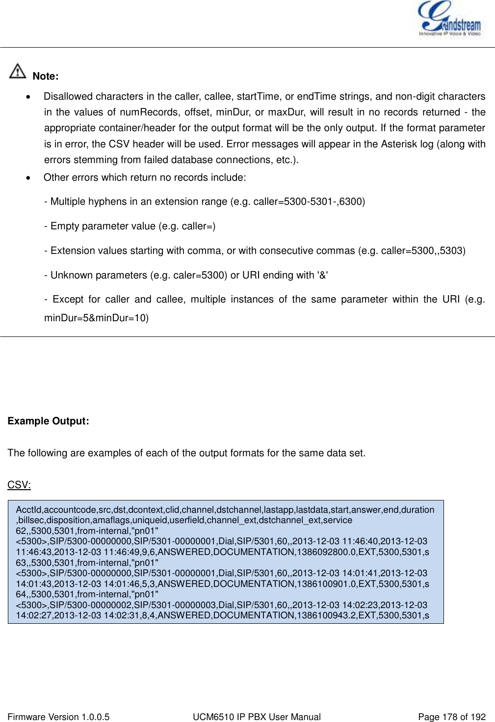
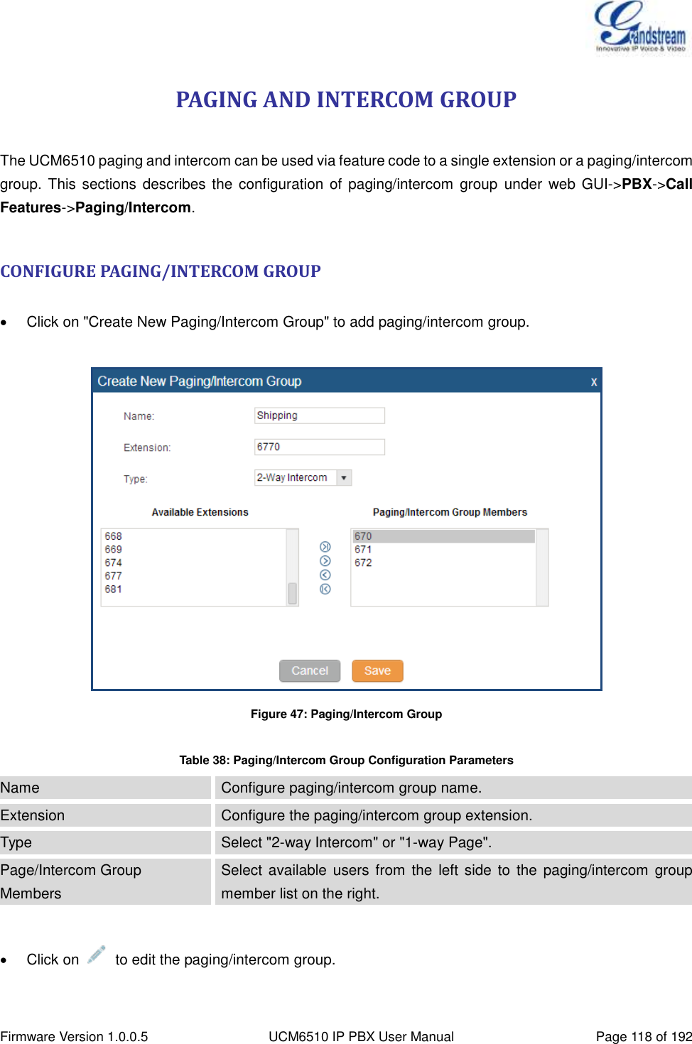
![Firmware Version 1.0.0.5 UCM6510 IP PBX User Manual Page 179 of 192 XML: JSON: <root> <cdr><AcctId>62</AcctId><accountcode></accountcode><src>5300</src><dst>5301</dst><dcontext>from-internal</dcontext><clid>&quot;pn01&quot; &lt;5300&gt;</clid><channel>SIP/5300-00000000</channel><dstchannel>SIP/5301-00000001</dstchannel><lastapp>Dial</lastapp><lastdata>SIP/5301,60,</lastdata><start>2013-12-03 11:46:40</start><answer>2013-12-03 11:46:43</answer><end>2013-12-03 11:46:49</end><duration>9</duration><billsec>6</billsec><disposition>ANSWERED</disposition><amaflags>DOCUMENTATION</amaflags><uniqueid>1386092800.0</uniqueid><userfield>EXT</userfield><channel_ext>5300</channel_ext><dstchannel_ext>5301</dstchannel_ext><service>s</service></cdr> <cdr><AcctId>63</AcctId><accountcode></accountcode><src>5300</src><dst>5301</dst><dcontext>from-internal</dcontext><clid>&quot;pn01&quot; &lt;5300&gt;</clid><channel>SIP/5300-00000000</channel><dstchannel>SIP/5301-00000001</dstchannel><lastapp>Dial</lastapp><lastdata>SIP/5301,60,</lastdata><start>2013-12-03 14:01:41</start><answer>2013-12-03 14:01:43</answer><end>2013-12-03 14:01:46</end><duration>5</duration><billsec>3</billsec><disposition>ANSWERED</disposition><amaflags>DOCUMENTATION</amaflags><uniqueid>1386100901.0</uniqueid><userfield>EXT</userfield><channel_ext>5300</channel_ext><dstchannel_ext>5301</dstchannel_ext><service>s</service></cdr> <cdr><AcctId>64</AcctId><accountcode></accountcode><src>5300</src><dst>5301</dst><dcontext>from-internal</dcontext><clid>&quot;pn01&quot; &lt;5300&gt;</clid><channel>SIP/5300-00000002</channel><dstchannel>SIP/5301-00000003</dstchannel><lastapp>Dial</lastapp><lastdata>SIP/5301,60,</lastdata><start>2013-12-03 14:02:23</start><answer>2013-12-03 14:02:27</answer><end>2013-12-03 14:02:31</end><duration>8</duration><billsec>4</billsec><disposition>ANSWERED</disposition><amaflags>DOCUMENTATION</amaflags><uniqueid>1386100943.2</uniqueid><userfield>EXT</userfield><channel_ext>5300</channel_ext><dstchannel_ext>5301</dstchannel_ext><service>s</service></cdr> </root> { "cdr": [ { "AcctId": "62", "accountcode": "", "src": "5300", "dst": "5301", "dcontext": "from-internal", "clid": "\"pn01\" <5300>", "channel": "SIP/5300-00000000", "dstchannel": "SIP/5301-00000001", "lastapp": "Dial", "lastdata": "SIP/5301,60,", "start": "2013-12-03 11:46:40", "answer": "2013-12-03 11:46:43", "end": "2013-12-03 11:46:49", "duration": "9", "billsec": "6", "disposition": "ANSWERED", "amaflags": "DOCUMENTATION", "uniqueid": "1386092800.0", "userfield": "EXT", "channel_ext": "5300", "dstchannel_ext": "5301", "service": "s" }, { "AcctId": "63", "accountcode": "", "src": "5300", "dst": "5301", "dcontext": "from-internal", "clid": "\"pn01\" <5300>", "channel": "SIP/5300-00000000", "dstchannel": "SIP/5301-00000001", "lastapp": "Dial", "lastdata": "SIP/5301,60,", "start": "2013-12-03 14:01:41", "answer": "2013-12-03 14:01:43", "end": "2013-12-03 14:01:46", "duration": "5", "billsec": "3", "disposition": "ANSWERED", "amaflags": "DOCUMENTATION", "uniqueid": "1386100901.0", "userfield": "EXT", "channel_ext": "5300", "dstchannel_ext": "5301", "service": "s" }, { "AcctId": "64", "accountcode": "", "src": "5300", "dst": "5301", "dcontext": "from-internal", "clid": "\"pn01\" <5300>", "channel": "SIP/5300-00000002", "dstchannel": "SIP/5301-00000003", "lastapp": "Dial", "lastdata": "SIP/5301,60,", "start": "2013-12-03 14:02:23", "answer": "2013-12-03 14:02:27", "end": "2013-12-03 14:02:31", "duration": "8", "billsec": "4", "disposition": "ANSWERED", "amaflags": "DOCUMENTATION", "uniqueid": "1386100943.2", "userfield": "EXT", "channel_ext": "5300", "dstchannel_ext": "5301", "service": "s" } ] }](https://usermanual.wiki/Grandstream-Networks/UCM6510.Users-Manual/User-Guide-2378753-Page-180.png)
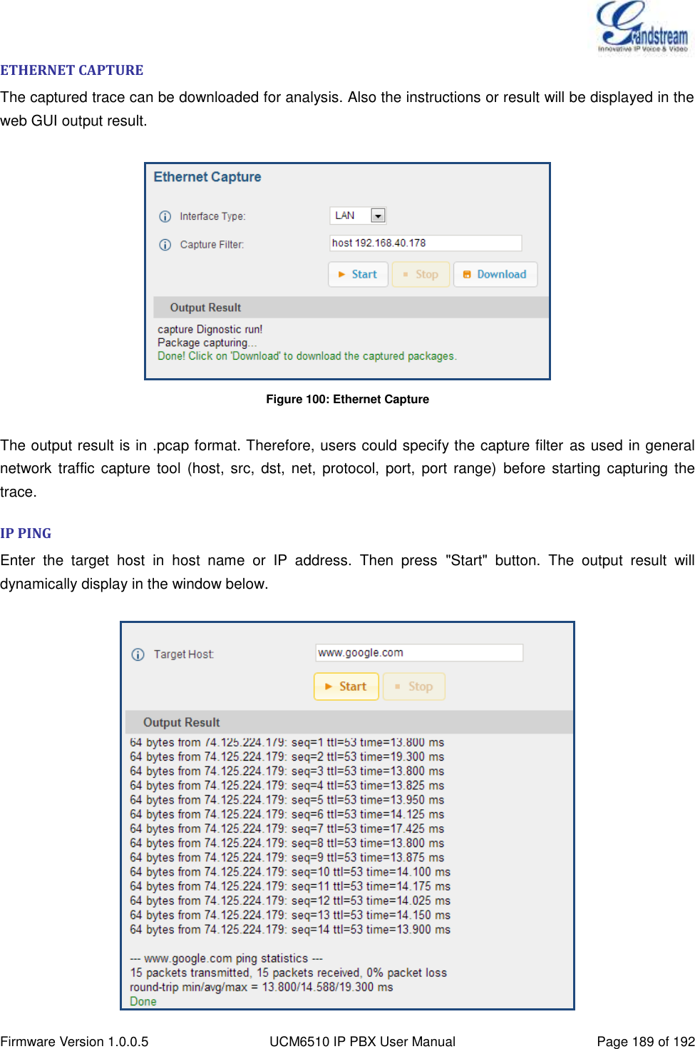
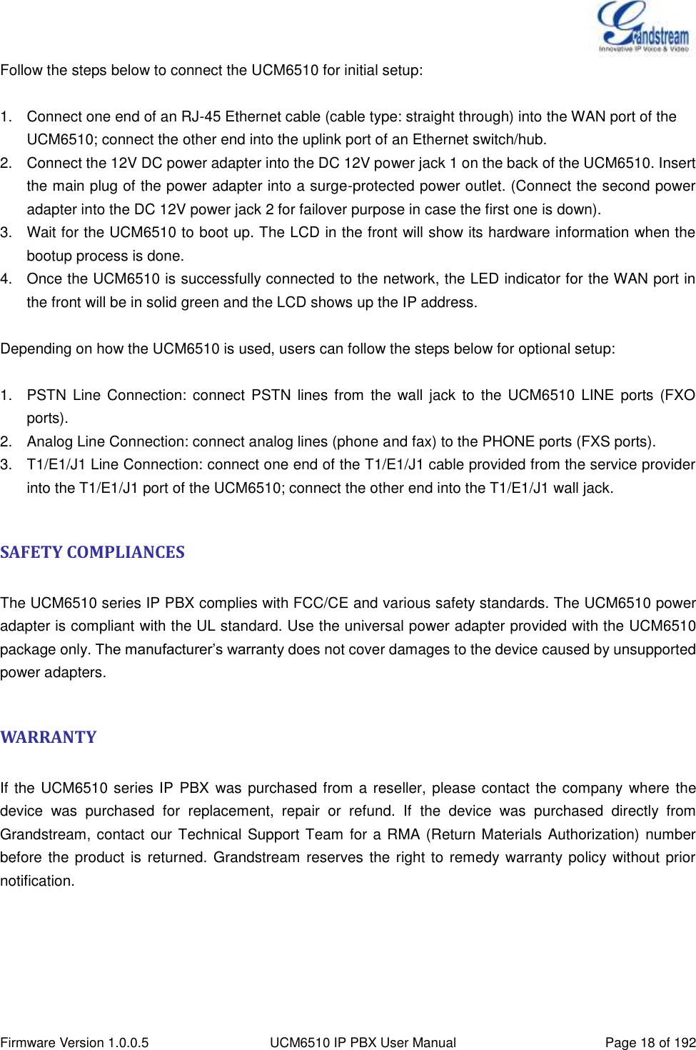
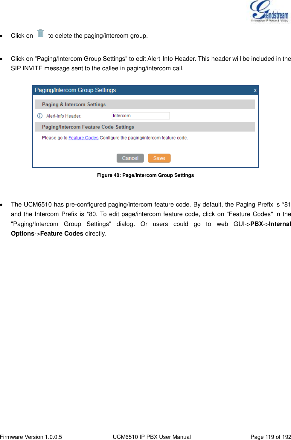
![Firmware Version 1.0.0.5 UCM6510 IP PBX User Manual Page 190 of 192 Figure 101: PING TRACEROUTE Enter the target host in host name or IP address. Then press "Start" button. The output result will dynamically display in the window below. Figure 102: Traceroute PRI SIGNALING TRACE Please see section [DIGITAL TRUNK TROUBLESHOOTING].](https://usermanual.wiki/Grandstream-Networks/UCM6510.Users-Manual/User-Guide-2378753-Page-191.png)