Grandstream Networks UCM6510 IP PBX User Manual
Grandstream Networks, Inc. IP PBX Users Manual
Contents
- 1. Users Manual
- 2. User Manual
Users Manual

UCM6510 IP PBX User Manual
Grandstream Networks, Inc.
UCM6510 IP PBX
User Manual

Firmware Version 1.0.0.5
UCM6510 IP PBX User Manual
Page 1 of 192
UCM6510 IP PBX User Manual
Index
CHANGE LOG ......................................................................................... 12
FIRMWARE VERSION 1.0.0.5 ............................................................................................................ 12
WELCOME ............................................................................................... 13
PRODUCT OVERVIEW ............................................................................ 14
FEATURE HIGHTLIGHTS ................................................................................................................... 14
TECHNICAL SPECIFICATIONS .......................................................................................................... 14
INSTALLATION ........................................................................................ 17
EQUIPMENT PACKAGING ................................................................................................................. 17
CONNECT YOUR UCM6510 ............................................................................................................... 17
CONNECT THE UCM6510 ........................................................................................................... 17
SAFETY COMPLIANCES .................................................................................................................... 18
WARRANTY ......................................................................................................................................... 18
GETTING STARTED ................................................................................ 20
USE THE LCD MENU .......................................................................................................................... 20
USE THE LED INDICATORS .............................................................................................................. 22
USE THE WEB GUI ............................................................................................................................. 22
ACCESS WEB GUI ...................................................................................................................... 22
WEB GUI CONFIGURATIONS ..................................................................................................... 24
WEB GUI LANGUAGES ............................................................................................................... 24
SAVE AND APPLY CHANGES ..................................................................................................... 25
MAKE YOUR FIRST CALL .................................................................................................................. 25
SYSTEM SETTINGS ................................................................................ 27
NETWORK SETTINGS........................................................................................................................ 27
BASIC SETTINGS ........................................................................................................................ 27
802.1X .......................................................................................................................................... 29
PORT FORWORDING.................................................................................................................. 30
FIREWALL ........................................................................................................................................... 30
STATIC DEFENSE ....................................................................................................................... 30
DYNAMIC DEFENSE ................................................................................................................... 33
FAIL2BAN ..................................................................................................................................... 33
CHANGE PASSWORD ........................................................................................................................ 34

Firmware Version 1.0.0.5
UCM6510 IP PBX User Manual
Page 2 of 192
LDAP SERVER .................................................................................................................................... 35
LDAP SERVER CONFIGURATIONS ........................................................................................... 35
LDAP PHONEBOOK .................................................................................................................... 36
LDAP CLIENT CONFIGURATIONS ............................................................................................. 38
HTTP SERVER .................................................................................................................................... 39
EMAIL SETTINGS ............................................................................................................................... 40
TIME SETTINGS ................................................................................................................................. 42
NTP SERVER ...................................................................................................................................... 44
PROVISIONING ....................................................................................... 45
OVERVIEW .......................................................................................................................................... 45
AUTO PROVISIONING ........................................................................................................................ 45
MANUAL PROVISIONING ................................................................................................................... 48
DISCOVERY ................................................................................................................................. 48
ASSIGNMENT .............................................................................................................................. 49
CREATE NEW DEVICE ................................................................................................................ 50
PROVISIONING ........................................................................................................................... 50
EXTENSIONS ........................................................................................... 51
CREATE NEW USER .......................................................................................................................... 51
CREATE NEW SIP EXTENSION ................................................................................................. 51
CREATE NEW IAX EXTENSION ................................................................................................. 54
CREATE NEW FXS EXTENSION ................................................................................................ 57
BATCH ADD EXTENSIONS ................................................................................................................ 60
BATCH ADD SIP EXTENSIONS .................................................................................................. 60
BATCH ADD IAX EXTENSIONS .................................................................................................. 63
EDIT EXTENSION ............................................................................................................................... 65
EXPORT EXTENSIONS ...................................................................................................................... 66
IMPORT EXTENSIONS ....................................................................................................................... 67
ANALOG TRUNKS .................................................................................. 68
ANALOG TRUNKS CONFIGURATION ............................................................................................... 68
PSTN DETECTION .............................................................................................................................. 70
ANALOG HARDWARE CONFIGURATION ......................................................................................... 73
DIGITAL TRUNKS .................................................................................... 76
DIGITAL HARDWARE CONFIGURATION .......................................................................................... 76
DIGITAL TRUNK CONFIGURATION ................................................................................................... 79
DIRECT OUTWARD DIALING (DOD) VIA DIGITAL TRUNKS ............................................................ 80
DIGITAL TRUNK TROUBLESHOOTING ............................................................................................. 80

Firmware Version 1.0.0.5
UCM6510 IP PBX User Manual
Page 3 of 192
VOIP TRUNKS ......................................................................................... 82
VOIP TRUNK CONFIGURATION ........................................................................................................ 82
DIRECT OUTWARD DIALING (DOD) VIA VOIP TRUNKS ................................................................. 89
CALL ROUTES ........................................................................................ 91
OUTBOUND ROUTES ........................................................................................................................ 91
INBOUND ROUTES ............................................................................................................................ 93
INBOUND RULE CONFIGURATIONS ......................................................................................... 94
BLACKLIST CONFIGURATIONS ................................................................................................. 96
CONFERENCE BRIDGE .......................................................................... 98
CONFERENCE BRIDGE CONFIGURATIONS ............................................................................ 98
JOIN A CONFERENCE CALL .................................................................................................... 100
INVITE OTHER PARTIES TO JOIN CONFERENCE ................................................................. 100
DURING THE CONFERENCE ................................................................................................... 101
RECORD CONFERENCE .......................................................................................................... 102
IVR ......................................................................................................... 104
CONFIGURE IVR .............................................................................................................................. 104
CREATE IVR PROMPT ..................................................................................................................... 106
RECORD NEW IVR PROMPT ................................................................................................... 106
UPLOAD IVR PROMPT.............................................................................................................. 107
LANGUAGE SETTINGS FOR VOICE PROMPT .................................... 108
DOWNLOAD AND INSTALL VOICE PROMPT PACKAGE ............................................................... 108
CUSTOMIZE AND UPLOAD VOICE PROMPT PACKAGE ................................................................111
VOICEMAIL ............................................................................................ 112
CONFIGURE VOICEMAIL ................................................................................................................. 112
VOICEMAIL EMAIL SETTINGS ......................................................................................................... 113
CONFIGURE VOICEMAIL GROUP................................................................................................... 114
RING GROUP ......................................................................................... 116
CONFIGURE RING GROUP ............................................................................................................. 116
PAGING AND INTERCOM GROUP ....................................................... 118
CONFIGURE PAGING/INTERCOM GROUP .................................................................................... 118
CALL QUEUE ........................................................................................ 120
CONFIGURE CALL QUEUE .............................................................................................................. 120

Firmware Version 1.0.0.5
UCM6510 IP PBX User Manual
Page 4 of 192
EXTENSION GROUPS ........................................................................... 123
CONFIGURE EXTENSION GROUPS ............................................................................................... 123
USE EXTENSION GROUPS ............................................................................................................. 123
PICKUP GROUPS .................................................................................. 125
CONFIGURE PICKUP GROUPS ...................................................................................................... 125
MUSIC ON HOLD ................................................................................... 126
FAX/T.38 ................................................................................................. 127
CONFIGURE FAX/T.38 ...................................................................................................................... 127
SAMPLE CONFIGURATION TO RECEIVE FAX FROM PSTN LINE ............................................... 128
SAMPLE CONFIGURATION FOR FAX-TO-EMAIL ........................................................................... 130
DISA ....................................................................................................... 132
BLF AND EVENT LIST ........................................................................... 134
BLF..................................................................................................................................................... 134
EVENT LIST ...................................................................................................................................... 134
DIAL BY NAME ...................................................................................... 137
DIAL BY NAME CONFIGURATION ................................................................................................... 137
CALL FEATURES .................................................................................. 140
FEATURE CODES ............................................................................................................................. 140
CALL RECORDING ........................................................................................................................... 143
CALL PARK ........................................................................................................................................ 144
PARK A CALL ............................................................................................................................. 144
RETRIEVE THE PARKED CALL ................................................................................................ 144
INTERNAL OPTIONS ............................................................................. 145
INTERNAL OPTIONS/GENERAL ...................................................................................................... 145
INTERNAL OPTIONS/JITTER BUFFER ........................................................................................... 146
INTERNAL OPTIONS/RTP SETTINGS ............................................................................................. 147
INTERNAL OPTIONS/STUN MONITOR ........................................................................................... 147
IAX SETTINGS ....................................................................................... 148
IAX SETTINGS/GENERAL ................................................................................................................ 148
IAX SETTINGS/REGISTRATION ...................................................................................................... 148
IAX SETTINGS/STATIC DEFENSE ................................................................................................... 149

Firmware Version 1.0.0.5
UCM6510 IP PBX User Manual
Page 5 of 192
SIP SETTINGS ....................................................................................... 151
SIP SETTINGS/GENERAL ................................................................................................................ 151
SIP SETTINGS/MISC ........................................................................................................................ 152
SIP SETTINGS/SESSION TIMER ..................................................................................................... 152
SIP SETTINGS/TCP and TLS ........................................................................................................... 153
SIP SETTINGS/NAT .......................................................................................................................... 154
SIP SETTINGS/TOS .......................................................................................................................... 155
STATUS AND REPORTING ................................................................... 157
PBX STATUS ..................................................................................................................................... 157
TRUNKS ..................................................................................................................................... 157
EXTENSIONS ............................................................................................................................. 158
QUEUES ..................................................................................................................................... 160
CONFERENCE ROOMS ............................................................................................................ 161
INTERFACES STATUS............................................................................................................... 161
PARKING LOT ............................................................................................................................ 162
SYSTEM STATUS.............................................................................................................................. 163
GENERAL ................................................................................................................................... 163
NETWORK ................................................................................................................................. 164
STORAGE USAGE ..................................................................................................................... 164
RESOURCE USAGE .................................................................................................................. 165
SYSTEM EVENTS ............................................................................................................................. 166
ALERT EVENTS LIST ................................................................................................................ 166
ALERT LOG ................................................................................................................................ 168
ALERT CONTACT ...................................................................................................................... 168
CDR ................................................................................................................................................... 169
DOWNLOADED CDR FILE ........................................................................................................ 171
STATISTICS ................................................................................................................................ 173
RECORDING FILES ................................................................................................................... 174
CDR API CONFIGURATION FILES ........................................................................................... 174
UPGRADING AND MAINTENANCE ...................................................... 180
UPGRADING ..................................................................................................................................... 180
UPGRADING VIA NETWORK .................................................................................................... 180
UPGRADING VIA LOCAL UPLOAD ........................................................................................... 181
NO LOCAL FIRMWARE SERVERS ........................................................................................... 183
BACKUP ............................................................................................................................................ 183
LOCAL BACKUP ........................................................................................................................ 184
DATA SYNC ................................................................................................................................ 184
RESTORE CONFIGURATION FROM BACKUP FILE ............................................................... 185

Firmware Version 1.0.0.5
UCM6510 IP PBX User Manual
Page 6 of 192
CLEANER .......................................................................................................................................... 186
RESET AND REBOOT ...................................................................................................................... 187
SYSLOG ............................................................................................................................................ 188
TROUBLESHOOTING ....................................................................................................................... 188
ETHERNET CAPTURE .............................................................................................................. 189
IP PING ....................................................................................................................................... 189
TRACEROUTE ........................................................................................................................... 190
PRI SIGNALING TRACE ............................................................................................................ 190
EXPERIENCING THE UCM6510 SERIES IP PBX ................................. 191

Firmware Version 1.0.0.5
UCM6510 IP PBX User Manual
Page 7 of 192
Table of Tables
UCM6510 IP PBX User Manual
Table 1: Technical Specifications................................................................................................................. 14
Table 2: UCM6510 Equipment Packaging .................................................................................................. 17
Table 3: LCD Menu Options ........................................................................................................................ 21
Table 4: UCM6510/UCM6510 LED INDICATORS ...................................................................................... 22
Table 5: UCM6510 Network Settings->Basic Settings ................................................................................ 27
Table 6: UCM6510 Network Settings->802.1X ........................................................................................... 29
Table 7: UCM6510 Network Settings->Port Forwarding ............................................................................. 30
Table 8: UCM6510 Firewall->Static Defense->Current Service .................................................................. 31
Table 9: Typical Firewall Settings ................................................................................................................ 31
Table 10: Firewall Rule Settings .................................................................................................................. 32
Table 11: UCM6510 Firewall Dynamic Defense .......................................................................................... 33
Table 12: Fail2Ban Settings ........................................................................................................................ 34
Table 13: HTTP Server Settings .................................................................................................................. 40
Table 14: Email Settings .............................................................................................................................. 40
Table 15: Auto Time Updating ..................................................................................................................... 42
Table 16: Auto Provision Settings ............................................................................................................... 47
Table 17: SIP Extension Configuration Parameters .................................................................................... 51
Table 18: IAX Extension Configuration Parameters .................................................................................... 54
Table 19: FXS Extension Configuration Parameters .................................................................................. 57
Table 20: Batch Add SIP Extension Parameters ......................................................................................... 60
Table 21: Batch Add IAX Extension Parameters ......................................................................................... 63
Table 22: Analog Trunk Configuration Parameters ..................................................................................... 68
Table 23: PSTN Detection For Analog Trunk .............................................................................................. 73
Table 24: PBX/Ports Config/Analog Hardware ............................................................................................ 74
Table 25: Ports Config/Digital Hardware: Edit Digital Ports ........................................................................ 77
Table 26: Digital Trunk Configuration Parameters ...................................................................................... 79
Table 27: SIP Trunk Configuration Parameters ........................................................................................... 82
Table 28: IAX Trunk Configuration Parameters........................................................................................... 86
Table 29: Outbound Route Configuration Parameters ................................................................................ 91
Table 30: Inbound Rule Configuration Parameters ..................................................................................... 94
Table 31: Conference Bridge Configuration Parameters ............................................................................ 98
Table 32: Conference Caller IVR Menu .................................................................................................... 101
Table 33: IVR Configuration Parameters .................................................................................................. 104
Table 34: Voicemail Settings ..................................................................................................................... 112
Table 35: Voicemail Email Settings ........................................................................................................... 114
Table 36: Voicemail Group Settings .......................................................................................................... 115
Table 37: Ring Group Parameters ............................................................................................................ 116
Table 38: Paging/Intercom Group Configuration Parameters ................................................................... 118

Firmware Version 1.0.0.5
UCM6510 IP PBX User Manual
Page 8 of 192
Table 39: Call Queue Configuration Parameters ...................................................................................... 120
Table 40: FAX/T.38 Settings ...................................................................................................................... 127
Table 41: DISA Settings ............................................................................................................................ 132
Table 42: Event List Settings ..................................................................................................................... 135
Table 43: UCM6510 Feature Codes ......................................................................................................... 140
Table 44: Internal Options/General ........................................................................................................... 145
Table 45: Internal Options/Jitter Buffer ...................................................................................................... 146
Table 46: Internal Options/RTP Settings ................................................................................................... 147
Table 47: Internal Options/STUN Monitor ................................................................................................. 147
Table 48: IAX Settings/General ................................................................................................................. 148
Table 49: IAX Settings/Registration .......................................................................................................... 148
Table 50: IAX Settings/Static Defense ...................................................................................................... 149
Table 51: SIP Settings/General ................................................................................................................. 151
Table 52: SIP Settings/Misc ...................................................................................................................... 152
Table 53: SIP Settings/Session Timer ....................................................................................................... 152
Table 54: SIP Settings/TCP and TLS ........................................................................................................ 153
Table 55: SIP Settings/NAT ....................................................................................................................... 154
Table 56: SIP Settings/ToS ........................................................................................................................ 155
Table 57: Trunk Status ............................................................................................................................... 158
Table 58: Extension Status ........................................................................................................................ 159
Table 59: Agent Status .............................................................................................................................. 160
Table 60: Interface Status Indicators ......................................................................................................... 161
Table 61: Parking Lot Status ..................................................................................................................... 162
Table 62: System Status->General ........................................................................................................... 163
Table 63: System Status->Network ........................................................................................................... 164
Table 64: CDR Filter Criteria ..................................................................................................................... 169
Table 65: CDR Statistics Filter Criteria ...................................................................................................... 173
Table 66: CDR API Configuration Files ..................................................................................................... 174
Table 67: CDR API URI Parameters ......................................................................................................... 175
Table 68: Network Upgrade Configuration ................................................................................................ 180
Table 69: Data Sync Configuration ........................................................................................................... 185
Table 70: Cleaner Configuration ............................................................................................................... 187

Firmware Version 1.0.0.5
UCM6510 IP PBX User Manual
Page 9 of 192
Table of Figures
UCM6510 IP PBX User Manual
Figure 1: UCM6510 Front View ................................................................................................................... 17
Figure 2: UCM6510 Back View ................................................................................................................... 17
Figure 3: UCM6510 web GUI Login Page .................................................................................................. 23
Figure 4: UCM6510 web GUI Language ..................................................................................................... 25
Figure 5: UCM6510 web GUI: Apply Changes ........................................................................................... 25
Figure 6: Create New Firewall Rule ............................................................................................................ 32
Figure 7: LDAP Server Configurations ........................................................................................................ 35
Figure 8: Default LDAP Phonebook DN ...................................................................................................... 36
Figure 9: Default LDAP Phonebook Attributes ............................................................................................ 36
Figure 10: Add LDAP Phonebook ............................................................................................................... 37
Figure 11: Edit LDAP Phonebook ............................................................................................................... 37
Figure 12: GXP2200 LDAP Phonebook Configuration ............................................................................... 39
Figure 13: UCM6510 Email Settings ........................................................................................................... 41
Figure 14: UCM6510 Email Settings: Send Test Email............................................................................... 42
Figure 15: Set Time Manually ..................................................................................................................... 43
Figure 16: UCM6510 Zero Config ............................................................................................................... 46
Figure 17: Auto Provision Settings .............................................................................................................. 47
Figure 18: Auto Discover ............................................................................................................................. 48
Figure 19: Discovered Devices ................................................................................................................... 49
Figure 20: Assign Extension To Device ....................................................................................................... 49
Figure 21: Create New Device .................................................................................................................... 50
Figure 22: Export Extensions ...................................................................................................................... 66
Figure 23: Export Extensions ...................................................................................................................... 67
Figure 24: UCM6510 FXO Tone Settings ................................................................................................... 71
Figure 25: UCM6510 PSTN Detection ........................................................................................................ 71
Figure 26: UCM6510 PSTN Detection: Auto Detect ................................................................................... 72
Figure 27: UCM6510 PSTN Detection: Semi-Auto Detect ......................................................................... 72
Figure 28: FXS Ports Signaling Preference ................................................................................................ 74
Figure 29: FXO Ports ACIM Settings .......................................................................................................... 74
Figure 30: Digital Hardware Configuration .................................................................................................. 76
Figure 31: Troubleshooting Digital Trunks .................................................................................................. 80
Figure 32: DOD extension selection ........................................................................................................... 90
Figure 33: Edit DOD .................................................................................................................................... 90
Figure 34: Blacklist Configuration Parameters ............................................................................................ 96
Figure 35: Conference Invitation From web GUI ...................................................................................... 100
Figure 36: Conference Recording ............................................................................................................. 103
Figure 37: Click On Prompt To Create IVR Prompt .................................................................................. 106
Figure 38: Record New IVR Prompt ......................................................................................................... 106

Firmware Version 1.0.0.5
UCM6510 IP PBX User Manual
Page 10 of 192
Figure 39: Upload IVR Prompt .................................................................................................................. 107
Figure 40: Language Settings For Voice Prompt ...................................................................................... 109
Figure 41: Voice Prompt Package List ...................................................................................................... 110
Figure 42: New Voice Prompt Language Added ........................................................................................111
Figure 43: Voicemail Email Settings ......................................................................................................... 113
Figure 44: Voicemail Group....................................................................................................................... 114
Figure 45: Ring Group ............................................................................................................................... 116
Figure 46: Ring Group Configuration ........................................................................................................ 117
Figure 47: Paging/Intercom Group ............................................................................................................ 118
Figure 48: Page/Intercom Group Settings ................................................................................................ 119
Figure 49: Call Queue ............................................................................................................................... 120
Figure 50: Agent Login Settings ................................................................................................................ 122
Figure 51: Edit Extension Group ............................................................................................................... 123
Figure 52: Select Extension Group in Outbound Route ............................................................................ 124
Figure 53: Edit Pickup Group .................................................................................................................... 125
Figure 54: Music On Hold Default Class ................................................................................................... 126
Figure 55: Configure Analog Trunk without Fax Detection ....................................................................... 128
Figure 56: Configure Extension For Fax Machine .................................................................................... 129
Figure 57: Configure Inbound Rule For Fax ............................................................................................. 129
Figure 58: Create Fax Extension .............................................................................................................. 130
Figure 59: Enable Fax Detection In Analog Trunk .................................................................................... 130
Figure 60: Inbound Route To Fax Extension ............................................................................................. 131
Figure 61: Create New DISA..................................................................................................................... 132
Figure 62: Create New Event List ............................................................................................................. 135
Figure 63: Create Dial By Name Group .................................................................................................... 137
Figure 64: Dial By Name Group In IVR Key Pressing Events .................................................................. 138
Figure 65: Dial By Name Group In IVR Key Pressing Events .................................................................. 138
Figure 66: Configure Extension First Name And Last Name .................................................................... 139
Figure 67: Download Recording File From CDR Page ............................................................................. 143
Figure 68: Status->PBX Status ................................................................................................................. 157
Figure 69: Trunk Status ............................................................................................................................. 157
Figure 70: Extension Status ...................................................................................................................... 159
Figure 71: Queue Status ........................................................................................................................... 160
Figure 72: Conference Room Status ......................................................................................................... 161
Figure 73: Parking Lot Status .................................................................................................................... 162
Figure 74: System Status->Storage Usage ............................................................................................... 165
Figure 75: System Status->Resource Usage ............................................................................................ 165
Figure 76: System Events->Alert Events Lists: Disk Usage ..................................................................... 166
Figure 77: System Events->Alert Events Lists: Modify Admin Password ................................................. 166
Figure 78: System Events->Alert Events Lists: Memory Usage ............................................................... 167
Figure 79: System Events->Alert Events Lists: System Reboot ............................................................... 167

Firmware Version 1.0.0.5
UCM6510 IP PBX User Manual
Page 11 of 192
Figure 80: System Events->Alert Events Lists: System Update ............................................................... 167
Figure 81: System Events->Alert Events Lists: System Crash ................................................................. 168
Figure 82: System Events->Alert Log ....................................................................................................... 168
Figure 83: CDR Filter ................................................................................................................................ 169
Figure 84: Call Report ............................................................................................................................... 170
Figure 85: Call Report Entry With Audio Recording File ........................................................................... 171
Figure 86: Downloaded CDR File Sample - Call To Shows "s" ................................................................ 171
Figure 87: Downloaded CDR File Sample - Source Channel and Dest Channel 1 .................................. 172
Figure 88: Downloaded CDR File Sample - Source Channel and Dest Channel 2 .................................. 172
Figure 89: Downloaded CDR File Sample - Source Channel and Dest Channel 3 .................................. 172
Figure 90: CDR Statistics .......................................................................................................................... 173
Figure 91: Network Upgrade ..................................................................................................................... 180
Figure 92: Local Upgrade .......................................................................................................................... 181
Figure 93: Upgrading Firmware Files ........................................................................................................ 182
Figure 94: Reboot UCM6510 .................................................................................................................... 182
Figure 95: Local Backup ........................................................................................................................... 184
Figure 96: Data Sync ................................................................................................................................ 185
Figure 97: Restore UCM6510 From Backup File ...................................................................................... 186
Figure 98: Cleaner .................................................................................................................................... 187
Figure 99: Reset and Reboot .................................................................................................................... 188
Figure 100: Ethernet Capture.................................................................................................................... 189
Figure 101: PING ...................................................................................................................................... 190
Figure 102: Traceroute .............................................................................................................................. 190

Firmware Version 1.0.0.5
UCM6510 IP PBX User Manual
Page 12 of 192
CHANGE LOG
This section documents significant changes from previous versions of the UCM6510 user manual. Only
major new features or major document updates are listed here. Minor updates for corrections or editing are
not documented here.
FIRMWARE VERSION 1.0.0.5
This is the initial version.
Firmware Version 1.0.0.5
UCM6510 IP PBX User Manual
Page 13 of 192
WELCOME
Thank you for purchasing Grandstream UCM6510 IP PBX appliance. UCM6500 is an innovative IP PBX
appliance designed to bring enterprise-grade unified communications and security protection features to
small-to-medium businesses (SMBs) in an easy-to-manage fashion. Powered by an advanced hardware
platform and revolutionary software functionalities, UCM6500 offers a breakthrough turnkey solution for
converged voice, video, data, fax, security surveillance, and mobility applications out of the box without
any extra license fees or recurring costs.
Caution:
Changes or modifications to this product not expressly approved by Grandstream, or operation of this
product in any way other than as detailed by this User Manual, could void your manufacturer warranty.
Warning:
Please do not use a different power adaptor with the UCM6510 as it may cause damage to the products
and void the manufacturer warranty.
This document is subject to change without notice. The latest electronic version of this user manual is
available for download here:
http://www.grandstream.com/support
Reproduction or transmittal of the entire or any part, in any form or by any means, electronic or print, for
any purpose without the express written permission of Grandstream Networks, Inc. is not permitted.

Firmware Version 1.0.0.5
UCM6510 IP PBX User Manual
Page 14 of 192
PRODUCT OVERVIEW
FEATURE HIGHTLIGHTS
1 GHz 4-core Cortex A9 application processor, large memory (1GB DDR3 RAM, 32GB NAND Flash),
and dedicated high performance multi-core DSP array for advanced voice processing.
Integrated 1 T1/E1/J1 (J1 is TBD) interface, 2 PSTN trunk FXO ports, 2 analog telephone FXS ports
with lifeline capability in case of power outage, and up to 50 SIP trunk accounts.
Gigabit network port(s) with integrated PoE, USB, SD card; integrated NAT router with advanced QoS
support.
Hardware DSP based 128ms-tail-length carrier-grade line echo cancellation (LEC), hardware based
caller ID/call progress tone and smart automated impedance matching for various countries.
Supports up to 2000 SIP endpoint registrations, up to 200 concurrent calls (up to 100 SRTP encrypted
concurrent calls), and up to 32 conference attendees.
Flexible dial plan, call routing, site peering, call recording, central control panel for endpoints,
integrated NTP server, and integrated LDAP contact directory.
Automated detection and provisioning of IP phones, video phones, ATAs, gateways, SIP cameras,
and other endpoints for easy deployment.
Strongest-possible security protection using SRTP, TLS, and HTTPS with hardware encryption
accelerator.
Provides Fail2ban preventing malicious attacks, supports Blacklist and Whitelist for efficient defense.
Manual and automatic recording for each SIP call and each trunk.
High availability helps rescue the server in a short time when hardware failure occurs (pending).
Automatically export previous day's data; periodically cleans up user data.
TECHNICAL SPECIFICATIONS
Table 1: Technical Specifications
Interfaces
Analog Telephone FXS Ports
2 RJ11 ports (both with lifetime capability in case of power outage)
PSTN Line FXO Ports
2 RJ11 ports (both with lifeline capability in case of power outage)
T1/J1 Interface
1 RJ45 port
Network Interfaces
3 ports: 1 LAN/1 WAN/1 Heartbeat.
Dual 10/100/1000Mbps RJ45 Ethernet port(s) with integrated PoE Plus
(IEEE 802.3at-2009)
NAT Router
Yes
Peripheral Ports
USB, SD

Firmware Version 1.0.0.5
UCM6510 IP PBX User Manual
Page 15 of 192
LED Indicators
Power 1/Power 2, PoE, USB, SD, T1/E1/J1(J1 is TBD), FXS 1/FXS 2,
FXO 1/FXO 2, LAN, WAN, Heartbeat
LCD Display
128x32 graphic LCD with DOWN and OK button
Reset Switch
Yes
Voice/Video Capabilities
Voice-over-Packet
Capabilities
LEC with NLP Packetized Voice Protocol Unit, 128ms-tail-length carrier
grade Line Echo Cancellation, Dynamic Jitter Buffer, Modem detection
and auto-switch to G.711
Voice and Fax Codecs
G.711 A-law/U-law, G.722, G.723.1 5.3K/6.3K, G.726, G.729A/B, iLBC,
GSM, AAL2-G.726-32, ADPCM; T.38
Video Codecs
H.264, H.263, H.263+
QoS
Layer 3 QoS, Layer 2 QoS
Signaling and Control
DTMF Methods
In Audio, RFC2833, and SIP INFO
Digital Signaling
PRI, SS7, MFC/R2
Provisioning Protocol and
Plug-and-Play
TFTP/HTTP/HTTPS, auto-discovery & auto-provisioning of
Grandstream IP endpoints via ZeroConfig (DHCP Option 66/multicast
SIP SUBSCRIBE/mDNS), eventlist between local and remote trunks
Network Protocols
TCP/UDP/IP, RTP/RTCP, ICMP, ARP, DNS, DDNS, DHCP, NTP, TFTP,
SSH, HTTP/HTTPS, PPPoE, SIP (RFC3261), STUN, SRTP, TLS, LAPD
Disconnect Methods
Call Progress Tone, Polarity Reversal, Hook Flash Timing, Loop Current
Disconnect, Busy Tone
Security
Media
SRTP, TLS, HTTPS, SSH
Physical
Universal Power Supply
Input: 100-240VAC, 50-60Hz
Output: DC+12VDC, 1.5A, 18W
Physical
Unit Weight: 2.165 KG
Package weight: 3.012 KG
Dimensions
440mm (L) x 185mm (W) x 44mm (H)
Environmental
Operating: Temperature 32 - 113oF / 0 - 45oC,
Humidity 10-90% (non-condensing)
Storage: Temperature 14 - 140oF / -10 - 60oC
Humidity 10-90% (non-condensing)

Firmware Version 1.0.0.5
UCM6510 IP PBX User Manual
Page 16 of 192
Mounting
Rack mount and Desktop
Additional Features
Multi-language Support
English, Simplified Chinese, Traditional Chinese, Spanish, French,
Portuguese, German, Russian, Italian, Polish, Czech for web GUI;
Customizable IVR/extension to support English, Chinese, British
English, German, Spanish, Greeks, French, Italian, Dutch, Polish,
Portuguese, Russian, Swedish, Turkish, Hebrew and Arabic
Caller ID
Bellcore/Telcordia, ETSI-FSK, ETSI-DTMF, SIN 227 - BT, NTT Japan
Polarity Reversal/ Wink
Yes, with enable/disable option upon call establishment and termination
Call Center
Multiple configurable call queues, automatic call distribution (ACD)
based on agent skills/availability busy level, in-queue announcement
Customizable Auto Attendant
Up to 5 layers of IVR (Interactive Voice Response)
Concurrent Calls
Up to 200 calls
Conference Bridges
Up to 5 bridges, up to 32 seats
Call Features
Call park, call forward, call transfer, DND, DISA, DOD, ring group,
pickup group, blacklist, paging/intercom and etc
Defense
Fail2ban, Alert events, Data sync (automatically export previous day's
data), Cleaner (periodically delete user data)
Compliance
FCC: Part 15 (CFR 47) Class B, Part 68
CE: EN55022 Class B, EN55024, EN61000-3-2, EN61000-3-3,
EN60950-1, TBR21, RoHS
TICK: AS/NZS CISPR 22 Class B, AS/NZS CISPR 24, AS/NZS
60950, AS/ACIF S002
ITU-T K.21 (Basic Level)
UL 60950 (power adapter)
T1: TIA-968-B Section 5.2.4
E1: TBR12/TBR13
E1: AS/ACIF S016
Firmware Version 1.0.0.5
UCM6510 IP PBX User Manual
Page 17 of 192
INSTALLATION
Before deploying and configuring the UCM6510 series, the device needs to be properly powered up and
connected to network. This section describes detailed information on installation, connection and warranty
policy of the UCM6510 series.
EQUIPMENT PACKAGING
Table 2: UCM6510 Equipment Packaging
Main Case
Yes (1)
Power Adaptor
Yes (2)
Ethernet Cable
Yes (1)
Wall Mount
Yes (2)
Screws
Yes (6)
Quick Installation Guide
Yes (1)
CONNECT YOUR UCM6510
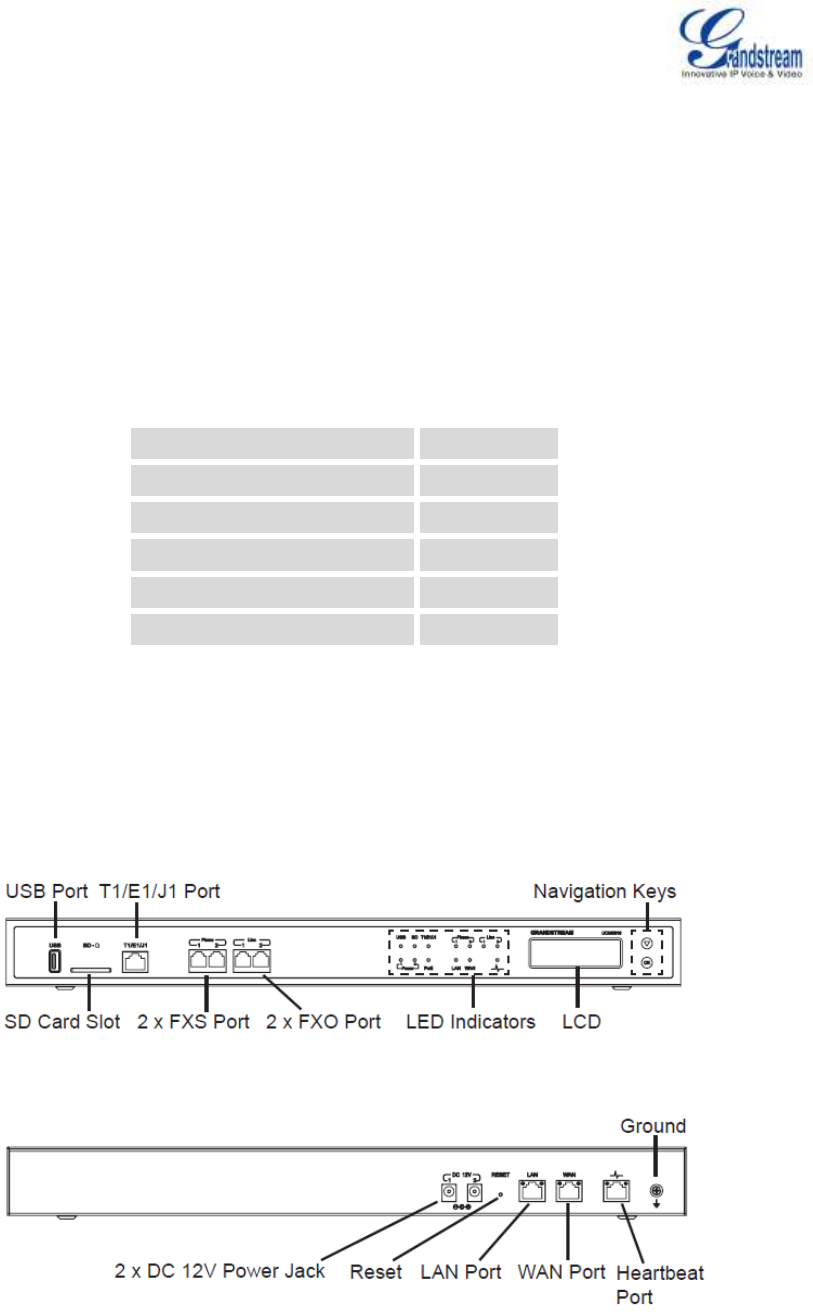
CONNECT THE UCM6510
Figure 1: UCM6510 Front View
Figure 2: UCM6510 Back View

Firmware Version 1.0.0.5
UCM6510 IP PBX User Manual
Page 18 of 192
Follow the steps below to connect the UCM6510 for initial setup:
1. Connect one end of an RJ-45 Ethernet cable (cable type: straight through) into the WAN port of the
UCM6510; connect the other end into the uplink port of an Ethernet switch/hub.
2. Connect the 12V DC power adapter into the DC 12V power jack 1 on the back of the UCM6510. Insert
the main plug of the power adapter into a surge-protected power outlet. (Connect the second power
adapter into the DC 12V power jack 2 for failover purpose in case the first one is down).
3. Wait for the UCM6510 to boot up. The LCD in the front will show its hardware information when the
bootup process is done.
4. Once the UCM6510 is successfully connected to the network, the LED indicator for the WAN port in
the front will be in solid green and the LCD shows up the IP address.
Depending on how the UCM6510 is used, users can follow the steps below for optional setup:
1. PSTN Line Connection: connect PSTN lines from the wall jack to the UCM6510 LINE ports (FXO
ports).
2. Analog Line Connection: connect analog lines (phone and fax) to the PHONE ports (FXS ports).
3. T1/E1/J1 Line Connection: connect one end of the T1/E1/J1 cable provided from the service provider
into the T1/E1/J1 port of the UCM6510; connect the other end into the T1/E1/J1 wall jack.
SAFETY COMPLIANCES
The UCM6510 series IP PBX complies with FCC/CE and various safety standards. The UCM6510 power
adapter is compliant with the UL standard. Use the universal power adapter provided with the UCM6510
package only. The manufacturer’s warranty does not cover damages to the device caused by unsupported
power adapters.
WARRANTY
If the UCM6510 series IP PBX was purchased from a reseller, please contact the company where the
device was purchased for replacement, repair or refund. If the device was purchased directly from
Grandstream, contact our Technical Support Team for a RMA (Return Materials Authorization) number
before the product is returned. Grandstream reserves the right to remedy warranty policy without prior
notification.

Firmware Version 1.0.0.5
UCM6510 IP PBX User Manual
Page 19 of 192
Warning:
Use the power adapter provided with the UCM6510 series IP PBX. Do not use a different power adapter as
this may damage the device. This type of damage is not covered under warranty.

Firmware Version 1.0.0.5
UCM6510 IP PBX User Manual
Page 20 of 192
GETTING STARTED
The UCM6510 provides LCD interface, LED indication and web GUI configuration interface.
The LCD displays hardware, software and network information. Users could also navigate in the LCD
menu for device information and basic network configuration.
The LED indication at the front of the device provides interface connection and activity status.
The web GUI gives users access to all the configurations and options for UCM6510 setup.
This section provides step-by-step instructions on how to use the LCD menu, LED indicators and web GUI
of the UCM6510. Once the basic settings are done, users could start making calls from UCM6510
extension registered on a SIP phone as described at the end of this section.
USE THE LCD MENU
Default LCD Display
By default, when the device is powered up, the LCD will show device model (e.g., UCM6510),
hardware version (e.g., V1.5A) and IP address. Press "Down" button and the system time will be
displayed (e.g., 2014-05-15 14:20).
Menu Access
Press "OK" button to start browsing menu options. Please see menu options in [Table 3: LCD Menu
Options].
Menu Navigation
Press the "Down" arrow key to browser different menu options. Press the "OK" button to select an
entry.
Exit
If "Back" option is available in the menu, select it to go back to the previous menu. For "Device Info"
"Network Info" and "Web Info" which do not have "Back" option, simply press the "OK" button to go
back to the previous menu. Also, the LCD will display default idle screen after staying in menu option
for 15 seconds.
LCD Backlight
The LCD backlight will be on upon key pressing. The backlight will go off after the LCD stays in idle for
30 seconds.
The following table shows the LCD menu options.

Firmware Version 1.0.0.5
UCM6510 IP PBX User Manual
Page 21 of 192
Table 3: LCD Menu Options
View Events
Critical Events
Other Events
Device Info
Hardware: Hardware version number
Software: Software version number
P/N: Part number
WAN MAC: WAN side MAC address (UCM6510 only)
LAN MAC: LAN side MAC address
Uptime: System up time since the last reboot.
Network Info
WAN Mode: DHCP, Static IP, or PPPoE
WAN IP: IP address
WAN Subnet Mask
LAN IP: IP address
LAN Subnet Mask
Network Menu
LAN Mode: Select LAN mode as DHCP, Static IP or PPPoE
WAN Mode: Select WAN mode as DHCP, Static IP or PPPoE
Factory Menu
Reboot
Factory Reset
LCD Test Patterns
Press "OK" to start. Then press "Down" button to test different LCD
patterns. When done, press "OK" button to exit.
Fan Mode
Select "Auto" or "On".
LED Test Patterns
Select "All On" "All Off" or "Blinking" and check LED status for USB, SD,
T1/E1/J1, Phone 1/Phone 2, Line 1/Line 2 ports. After the LED test, select
"Back" in the menu and the device will show the LED actual status again.
RTC Test Patterns
Select "2022-02-22 22:22" or "2011-01-11 11:11" to start the RTC
(Real-Time Clock) test pattern. Check the system time from LCD idle
screen by pressing "DOWN" button, or from web GUI->System
Status->General page. After the test, reboot the device manually and the
device will display the correct time.
Firmware Version 1.0.0.5
UCM6510 IP PBX User Manual
Page 22 of 192
Hardware Testing
Select "Test SVIP" to perform SVIP test on the device. This is mainly for
factory testing purpose which verifies the hardware connection inside the
device. The diagnostic result displays on the LCD after the test is done.
Web Info
Protocol: Web access protocol. HTTP or HTTPS. By default it's HTTPS
Port: Web access port number. By default it's 8089
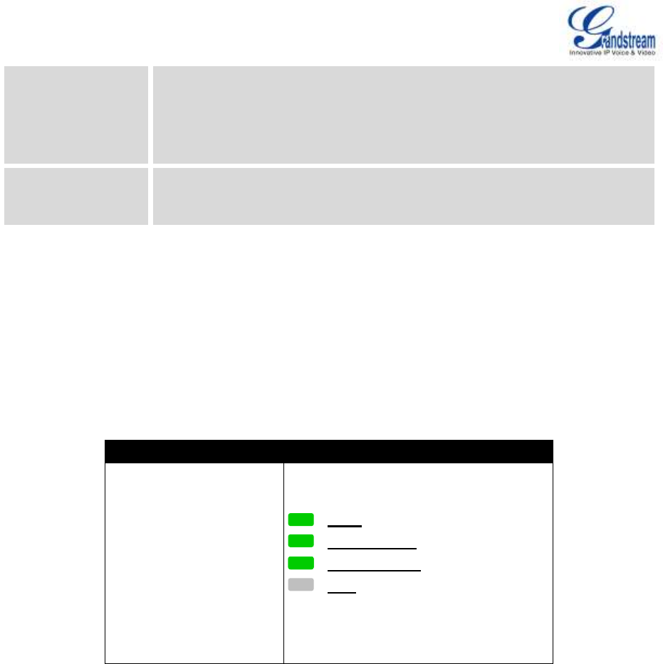
USE THE LED INDICATORS
The UCM6510 has LED indicators in the front to display connection status. The following table shows the
status definitions.
Table 4: UCM6510/UCM6510 LED INDICATORS
USE THE WEB GUI
ACCESS WEB GUI
The UCM6510 embedded Web server responds to HTTP/HTTPS GET/POST requests. Embedded HTML
pages allow users to configure the device through a Web browser such as Microsoft IE, Mozilla Firefox,
Google Chrome and etc.
LED Indicator
LED Status
Power 1/Power 2
PoE
LAN
WAN
USB
SD
T1/E1/J
Phone 1 /Phone 2 (FXS)
Line 1/Line 2 FXO
Solid: Connected
Fast Blinking: Data Transferring
Slow Blinking: Trying to connect
OFF: Not Connected
Firmware Version 1.0.0.5
UCM6510 IP PBX User Manual
Page 23 of 192
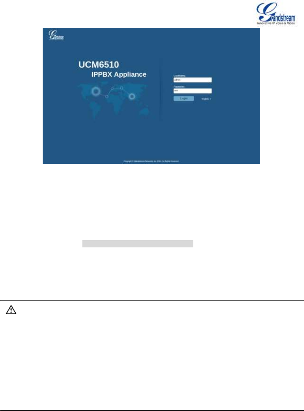
Figure 3: UCM6510 web GUI Login Page
To access the web GUI:
1. Connect the computer to the same network as the UCM6510.
2. Ensure the device is properly powered up and shows its IP address on the LCD.
3. Open a web browser on the computer and enter the IP address in the address bar. The web login page
will display as shown in [Figure 3: UCM6510 web GUI Login Page].
4. Enter the administrator’s login and password to access the web configuration menu. The default
administrator's username and password is "admin" and "admin". It is highly recommended to change
the default password after login for the first time.
Note:
By default, the UCM6510 has "Redirect From Port 80" enabled. Therefore, if users type in the UCM6510
IP address in the web browser, the web page will be automatically redirected to the page using HTTPS
and port 8089. For example, if the LCD shows 192.168.40.167, please enter 192.168.40.167 in your web
browser and the web page will be redirected to:
https://192.168.40.167:8089
The option "Redirect From Port 80" can be configured under the UCM6510 web GUI->Settings->HTTP
Server.

Firmware Version 1.0.0.5
UCM6510 IP PBX User Manual
Page 24 of 192
WEB GUI CONFIGURATIONS
There are four main sections in the web GUI for users to view the PBX status, configure and manage the
PBX.
Status: Displays PBX status, System Status, System Events and CDR.
PBX: To configure extensions, trunks, call routes, zero config for auto provisioning, call features,
internal options, IAX settings, SIP settings, as well as ports configuration for digital trunks.
Settings: To configure network settings, firewall settings, change password, LDAP Server, HTTP
Server, Email Settings, Time Settings and NTP server.
Maintenance: To perform firmware upgrade, backup configurations, cleaner setup, reset/reboot,
syslog setup and troubleshooting.
WEB GUI LANGUAGES
Currently the UCM6510 web GUI supports the following languages:
English
Simplified Chinese
Traditional Chinese
Spanish
French
Portuguese
Russian
Italian
Polish
German
Czech
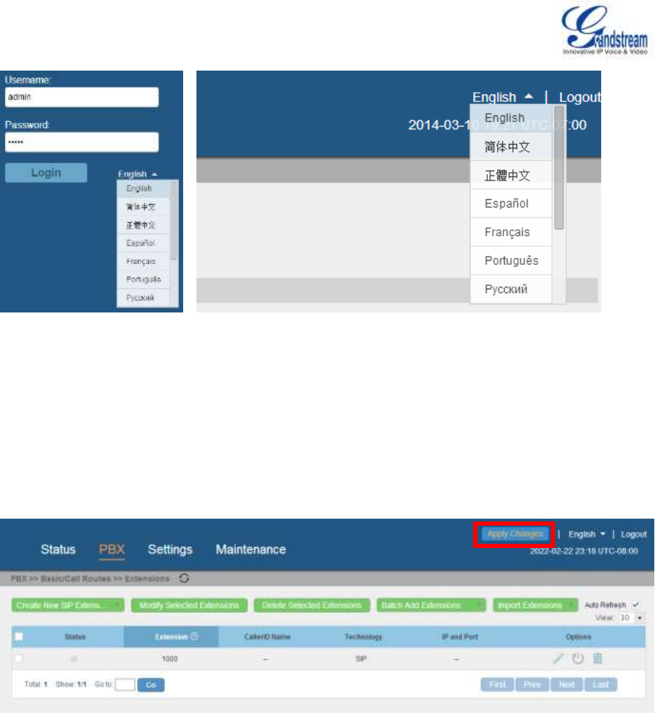
Users can select the displayed language in web GUI login page, or at the upper right of the web GUI after
logging in.
Firmware Version 1.0.0.5
UCM6510 IP PBX User Manual
Page 25 of 192
Figure 4: UCM6510 web GUI Language
SAVE AND APPLY CHANGES
Click on "Save" button after configuring the web GUI options in one page. After saving all the changes,
make sure click on "Apply Changes" button on the upper right of the web page to submit all the changes. If
the change requires reboot to take effect, a prompted message will pop up for you to reboot the device.
Figure 5: UCM6510 web GUI: Apply Changes
MAKE YOUR FIRST CALL
Power up the UCM6510 and your SIP end point phone. Connect both devices to the network. Then follow
the steps below to make your first call.
1. Log in the UCM6510 web GUI, go to PBX->Basic/Call Routes->Extensions.

Firmware Version 1.0.0.5
UCM6510 IP PBX User Manual
Page 26 of 192
2. Click on "Create New SIP Extension" to create a new extension. You will need User ID, Password and
Voicemail Password information to register and use the extension later.
3. Register the extension on your phone with the SIP User ID, SIP server and SIP Password information.
The SIP server address is the UCM6510 IP address.
4. When your phone is registered with the extension, dial *97 to access the voicemail box. Enter the
Voicemail Password once you hear "Password" voice prompt.
5. Once successfully logged in to the voicemail, you will be prompted with the Voice Mail Main menu.
6. You are successfully connected to the PBX system now.

Firmware Version 1.0.0.5
UCM6510 IP PBX User Manual
Page 27 of 192
SYSTEM SETTINGS
This section explains configurations for system-wide parameters on the UCM6510. Those parameters
include Network Settings, Firewall, Change Password, LDAP server, HTTP server, Email settings, Time
Settings and NTP Server settings.
NETWORK SETTINGS
After successfully connecting the UCM6510 to the network for the first time, users could login the web GUI
and go to Settings->Network Settings to configure the network parameters for the device. Select each tab
in web GUI->Settings->Network Settings page to configure LAN/WAN settings, 802.1X and Port
Forwarding.
BASIC SETTINGS
Please refer to the following tables for basic network configuration parameters on the UCM6510.
Table 5: UCM6510 Network Settings->Basic Settings
Method
Select "Route", "Switch" or "Dual" mode on the network interface of UCM6510.
The default setting is "Route".
Route
WAN port interface will be used for uplink connection. LAN port interface will
be used to serve as router.
Switch
WAN port interface will be used for uplink connection. LAN port interface will
be used as bridge for PC connection.
Dual
Both ports can be used for uplink connection. Users will need assign LAN 1
or LAN 2 as the default interface in option "Default Interface" and configure
"Gateway IP" for this interface.
Preferred DNS Server
Enter the preferred DNS server address.
WAN (when "Method" is set to "Route")
IP Method
Select DHCP, Static IP, or PPPoE. The default setting is DHCP.
Gateway IP
Enter the gateway IP address for static IP settings. The default setting is 0.0.0.0.
Subnet Mask
Enter the subnet mask address for static IP settings. The default setting is

Firmware Version 1.0.0.5
UCM6510 IP PBX User Manual
Page 28 of 192
255.255.0.0.
IP Address
Enter the IP address for static IP settings. The default setting is 192.168.0.160.
DNS Server 1
Enter the DNS server 1 address for static IP settings. The default setting is
0.0.0.0.
DNS Server 2
Enter the DNS server 2 address for static IP settings.
User Name
Enter the user name to connect via PPPoE.
Password
Enter the password to connect via PPPoE.
Layer 2 QoS
802.1Q/VLAN Tag
Assign the VLAN tag of the layer 2 QoS packets for WAN port. The default value
is 0.
Layer 2 QoS 802.1p
Priority Value
Assign the priority value of the layer 2 QoS packets for WAN port. The default
value is 0.
LAN (when Method is set to "Route")
IP Address
Enter the IP address assigned to LAN port. The default setting is 192.168.2.1.
Subnet Mask
Enter the subnet mask. The default setting is 255.255.255.0.
DHCP Server Enable
Enable or disable DHCP server capability. The default setting is "Yes".
DNS Server 1
Enter DNS server address 1. The default setting is 8.8.8.8.
DNS Server 2
Enter DNS server address 2. The default setting is 208.67.222.222.
Allow IP Address From
Enter the DHCP IP Pool starting address. The default setting is 192.168.2.100.
Allow IP Address To
Enter the DHCP IP Pool ending address. The default setting is 192.168.2.254.
Default IP Lease Time
Enter the IP lease time (in seconds). The default setting is 43200.
LAN (when Method is set to "Switch")
IP Method
Select DHCP, Static IP, or PPPoE. The default setting is DHCP.
Gateway IP
Enter the gateway IP address for static IP settings. The default setting is 0.0.0.0.
Subnet Mask
Enter the subnet mask address for static IP settings. The default setting is
255.255.0.0.
IP Address
Enter the IP address for static IP settings. The default setting is 192.168.0.160.
DNS Server 1
Enter the DNS server 1 address for static IP settings. The default setting is
0.0.0.0.
DNS Server 2
Enter the DNS server 2 address for static IP settings.
User Name
Enter the user name to connect via PPPoE.
Password
Enter the password to connect via PPPoE.
Layer 2 QoS
802.1Q/VLAN Tag
Assign the VLAN tag of the layer 2 QoS packets for LAN port. The default value
is 0.
Layer 2 QoS 802.1p
Priority Value
Assign the priority value of the layer 2 QoS packets for LAN port. The default
value is 0.

Firmware Version 1.0.0.5
UCM6510 IP PBX User Manual
Page 29 of 192
LAN 1 / LAN 2 (when Method is set to "Dual")
Default Interface
If "Dual" is selected as "Method", users will need assign the default interface to
be LAN 1 (mapped to UCM6510 WAN port) or LAN 2 (mapped to UCM6510 LAN
port) and then configure network settings for LAN 1/LAN 2. The default interface
is LAN 2.
IP Method
Select DHCP, Static IP, or PPPoE. The default setting is DHCP.
Gateway IP
Enter the gateway IP address for static IP settings when the port is assigned as
default interface. The default setting is 0.0.0.0.
IP Address
Enter the IP address for static IP settings. The default setting is 192.168.0.160.
Subnet Mask
Enter the subnet mask address for static IP settings. The default setting is
255.255.0.0.
DNS Server 1
Enter the DNS server 1 address for static IP settings. The default setting is
0.0.0.0.
DNS Server 2
Enter the DNS server 2 address for static IP settings.
User Name
Enter the user name to connect via PPPoE.
Password
Enter the password to connect via PPPoE.
Layer 2 QoS
802.1Q/VLAN Tag
Assign the VLAN tag of the layer 2 QoS packets for LAN port. The default value
is 0.
Layer 2 QoS 802.1p
Priority Value
Assign the priority value of the layer 2 QoS packets for LAN port. The default
value is 0.
802.1X
Table 6: UCM6510 Network Settings->802.1X
802.1X Mode
Select 802.1X mode. The default setting is "Disable". The supported 802.1X
mode are:
EAP-MD5
EAP-TLS
EAP-PEAPv0/MSCHAPv2
Identity
Enter 802.1X mode identity information.
MD5 Password
Enter 802.1X mode MD5 password information.
802.1X Certificate
Select 802.1X certificate from local PC and then upload.
802.1X Client
Certificate
Select 802.1X client certificate from local PC and then upload.

Firmware Version 1.0.0.5
UCM6510 IP PBX User Manual
Page 30 of 192
PORT FORWORDING
The UCM6510 network interface supports router functions which provides users the ability to do port
forwarding. If the UCM6510 is set to "Route" under web GUI->Settings->Network Settings->Basic
Settings: Method, port forwarding is available for configuration.
The port forwarding configuration is under web GUI->Settings->Network Settings->Port Forwarding
page. Please see related settings in the table below.
Table 7: UCM6510 Network Settings->Port Forwarding
WAN Port
Specify the WAN port number. Up to 8 ports can be configured.
LAN IP
Specify the LAN IP address.
LAN Port
Specify the LAN port number.
Protocol Type
Select protocol type "UDP Only", "TCP Only" or "TCP/UDP" for the forwarding in
the selected port. The default setting is "UDP Only".
FIREWALL
The UCM6510 provides users firewall configurations to prevent certain malicious attack to the UCM6510
system. Users could configure to allow, restrict or reject specific traffic through the device for security and
bandwidth purpose. The UCM6510 also provides Fail2ban feature for authentication errors in SIP
REGISTER, INVITE and SUBSCRIBE. To configure firewall settings in UCM6510, go to web
GUI->Settings->Firewall page.
STATIC DEFENSE
Under web GUI->Settings->Firewall->Static Defense page, users will see the following information:
Current service information with port, process and type.
Typical firewall settings.
Custom firewall settings.
The following table shows a sample current service status running on the UCM6510.

Firmware Version 1.0.0.5
UCM6510 IP PBX User Manual
Page 31 of 192
Table 8: UCM6510 Firewall->Static Defense->Current Service
Port
Process
Type
Protocol or Service
7777
Asterisk
tcp/IPv4
SIP
389
Slapd
tcp/IPv4
LDAP
22
Dropbear
tcp/IPv4
SSH
80
Lighthttpd
tcp/IPv4
HTTP
8089
Lighthttpd
tcp/IPv4
HTTPS
69
Opentftpd
udp/IPv4
TFTP
9090
Asterisk
udp/IPv4
SIP
6060
zero_config
udp/IPv4
UCM6510 zero_config service
5060
Asterisk
udp/IPv4
SIP
4569
Asterisk
udp/IPv4
SIP
5353
zero_config
udp/IPv4
UCM6510 zero_config service
37435
Syslogd
udp/IPv4
Syslog
For typical firewall settings, users could configure the following options on the UCM6510.
Table 9: Typical Firewall Settings
Ping Defense
Enable
If enabled, ICMP response will not be allowed for Ping request. The default
setting is disabled. To enable or disable it, click on the check box for the LAN
or WAN interface.
SYN-Flood Defense
Enable
Enable to prevent SYN Flood denial-of-service attack to the device. The
default setting is disabled. To enable or disable it, click on the check box for
the LAN or WAN interface.
Ping-of-Death
Defense Enable
Enable to prevent Ping-of-Death attack to the device. The default setting is
disabled. To enable or disable it, click on the check box for the LAN or WAN
interface.
Under "Custom Firewall Settings", users could create new rules to accept, reject or drop certain traffic going
through the UCM6510. To create new rule, click on "Create New Rule" button and a new window will pop up
for users to specify rule options.
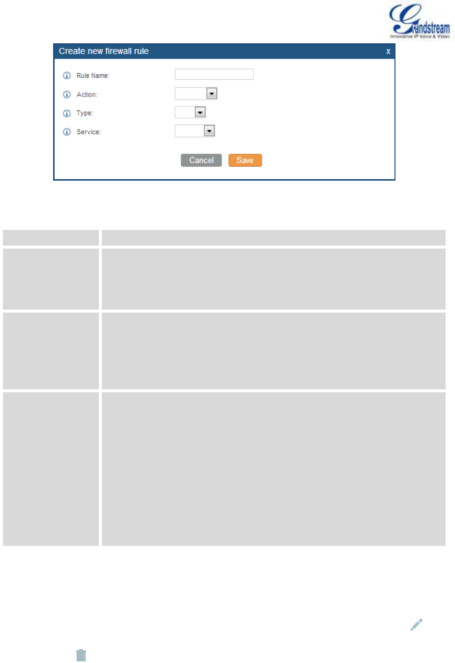
Firmware Version 1.0.0.5
UCM6510 IP PBX User Manual
Page 32 of 192
Figure 6: Create New Firewall Rule
Table 10: Firewall Rule Settings
Rule Name
Specify the Firewall rule name to identify the firewall rule.
Action
Select the action for the Firewall to perform.
ACCEPT
REJECT
DROP
Type
Select the traffic type.
IN
If selected, users will need specify the network interface "LAN", "WAN" or
"Both" for the incoming traffic.
OUT
Service
Select the service type.
FTP
SSH
Telnet
TFTP
HTTP
LDAP
Custom
If selected, users will need specify Source (IP and port), Destination (IP
and port) and Protocol (TCP, UDP or Both) for the service.
Save the change and click on "Apply" button. Then submit the configuration by clicking on "Apply Changes"
on the upper right of the web page. The new rule will be listed at the bottom of the page with sequence
number, rule name, action, protocol, type, source, destination and operation. Users can click on to edit
the rule, or select to delete the rule.

Firmware Version 1.0.0.5
UCM6510 IP PBX User Manual
Page 33 of 192
DYNAMIC DEFENSE
Dynamic defense can blacklist hosts dynamically when the UCM6510 is set to "Route" under web
GUI->Settings->Network Settings->Basic Settings: Method. If enabled, the traffic coming into the
UCM6510 can be monitored, which helps prevent massive connection attempts or brute force attacks to the
device. The blacklist can be created and updated by the UCM6510 firewall, which will then be displayed in
the web page. Please refer to the following table for dynamic defense options on the UCM6510.
Table 11: UCM6510 Firewall Dynamic Defense
Dynamic Defense
Enable
Enable dynamic defense. The default setting is disabled.
Periodical Time
Interval
Configure the dynamic defense periodic time interval (in minutes). If the
number of TCP connections from a host exceeds the connection threshold
within this period, this host will be added into Blacklist. The valid value is
between 1 to 59 when dynamic defense is turned on. The default setting is
59.
Blacklist Update
Interval
Configure the blacklist update time interval (in seconds). The default setting is
120.
Connection
Threshold
Configure the connection threshold. Once the number of connections from
the same host reaches the threshold, it will be added into the blacklist. The
default setting is 100.
Dynamic Defense
Whitelist
Configure the dynamic defense whitelist.
For example,
192.168.1.3
192.168.1.4
FAIL2BAN
Fail2Ban feature on the UCM6510 provides intrusion detection and prevention for authentication errors in
SIP REGISTER, INVITE and SUBSCRIBE. Once the entry is detected within "Max Retry Duration", the
UCM6510 will take action to forbid the host for certain period as defined in "Banned Duration". This feature
helps prevent SIP brute force attacks to the PBX system.
Firmware Version 1.0.0.5
UCM6510 IP PBX User Manual
Page 34 of 192
Table 12: Fail2Ban Settings
Global Settings
Enable Fail2Ban
Enable Fail2Ban. The default setting is disabled. Please make sure both "Enable
Fail2Ban" and "Asterisk Service" are turned on in order to use Fail2Ban for SIP
authentication on the UCM6510.
Banned Duration
Configure the duration (in seconds) for the detected host to be banned. The
default setting is 300. If set to -1, the host will be always banned.
Max Retry Duration
Within this duration (in seconds), if a host exceeds the max times of retry as
defined in "MaxRetry", the host will be banned. The default setting is 5.
MaxRetry
Configure the number of authentication failures during "Max Retry Duration"
before the host is banned. The default setting is 10.
Fail2Ban Whitelist
Configure IP address, CIDR mask or DNS host in the whiltelist. Fail2Ban will not
ban the host with matching address in this list. Up to 5 addresses can be added
into the list.
Local Settings
Asterisk Service
Enable Asterisk service for Fail2Ban. The default setting is disabled. Please
make sure both "Enable Fail2Ban" and "Asterisk Service" are turned on in order
to use Fail2Ban for SIP authentication on the UCM6510.
Port
Configure the listening port number for the service. Currently only 5060 (for
UDP) is supported.
MaxRetry
Configure the number of authentication failures during "Max Retry Duration"
before the host is banned. The default setting is 10. Please make sure this option
is properly configured as it will override the "MaxRetry" value under "Global
Settings".
CHANGE PASSWORD
After login the web GUI for the first time, it is highly recommended for users to change the default password
"admin" to a more complicated password for security purpose. Follow the steps below to change the web
GUI access password.
1. Go to web GUI->Settings->Change Password page.
2. Enter the old password first.
3. Enter the new password and retype the new password to confirm. The new password has to be at least
4 characters.
4. Click on "Save" and the user will be automatically logged out.
5. Once the web page comes back to the login page again, enter the username "admin" and the new
password to login.
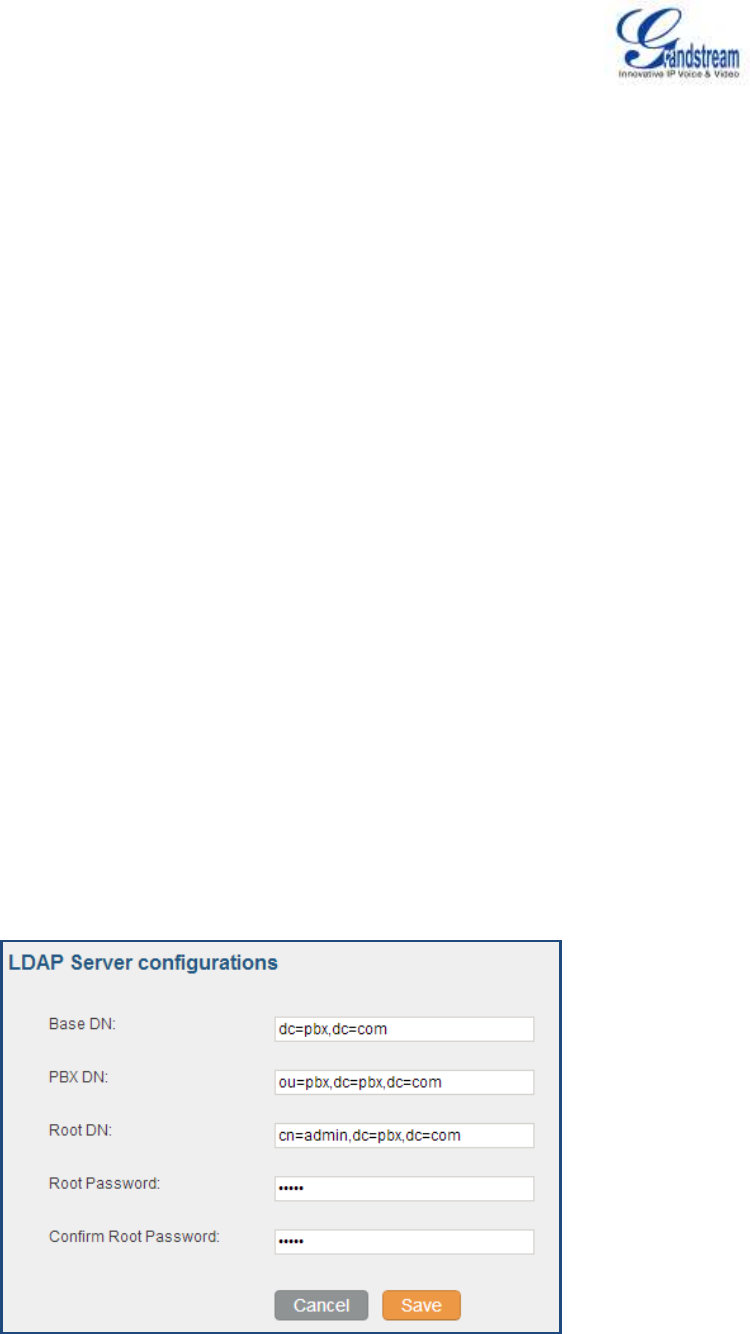
Firmware Version 1.0.0.5
UCM6510 IP PBX User Manual
Page 35 of 192
LDAP SERVER
The UCM6510 has an embedded LDAP server for users to manage corporate phonebook in a centralized
manner.
By default, the LDAP server has generated the first phonebook with PBX DN "ou=pbx,dc=pbx,dc=com"
based on the UCM6510 user extensions already.
Users could add new phonebook with a different Phonebook DN for other external contacts. For
example, "ou=people,dc=pbx,dc=com".
All the phonebooks in the UCM6510 LDAP server have the same Base DN "dc=pbx,dc=com".
If users have the Grandstream phone provisioned by the UCM6510, the LDAP directory has been set up on
the phone and can be used right away for users to access all phonebooks.
Additionally, users could manually configure the LDAP client settings to manipulate the built-in LDAP server
on the UCM6510. If the UCM6510 has multiple LDAP phonebooks created, in the LDAP client configuration,
users could use "dc=pbx,dc=com" as Base DN to have access to all phonebooks on the UCM6510 LDAP
server, or use a specific phonebook DN, for example "ou=people,dc=pbx,dc=com", to access to phonebook
with Phonebook DN "ou=people,dc=pbx,dc=com " only.
To access LDAP Server settings, go to web GUI->Settings->LDAP Server.
LDAP SERVER CONFIGURATIONS
The following figure shows the default LDAP server configurations on the UCM6510.
Figure 7: LDAP Server Configurations
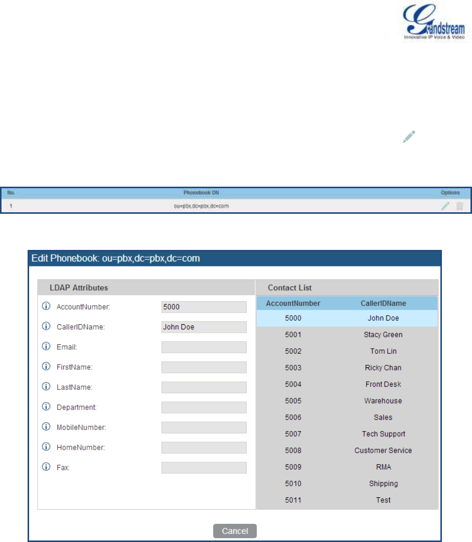
Firmware Version 1.0.0.5
UCM6510 IP PBX User Manual
Page 36 of 192
The UCM6510 LDAP server supports anonymous access (read-only) by default. Therefore the LDAP client
doesn't have to configure username and password to access the phonebook directory. The "Root DN" and
"Root Password" here are for LDAP management and configuration where users will need provide for
authentication purpose before modifying the LDAP information.
The default phonebook list in this LDAP server can be viewed and edited by clicking on for the first
phonebook under LDAP Phonebook.
Figure 8: Default LDAP Phonebook DN
Figure 9: Default LDAP Phonebook Attributes
LDAP PHONEBOOK
Users could use the default phonebook, edit the default phonebook as well as add new phonebook on the
LDAP server. The first phonebook with default phonebook dn "ou=pbx,dc=pbx,dc=com" displayed on the
LDAP server page is for extensions in this PBX. Users cannot add or delete contacts directly. The contacts
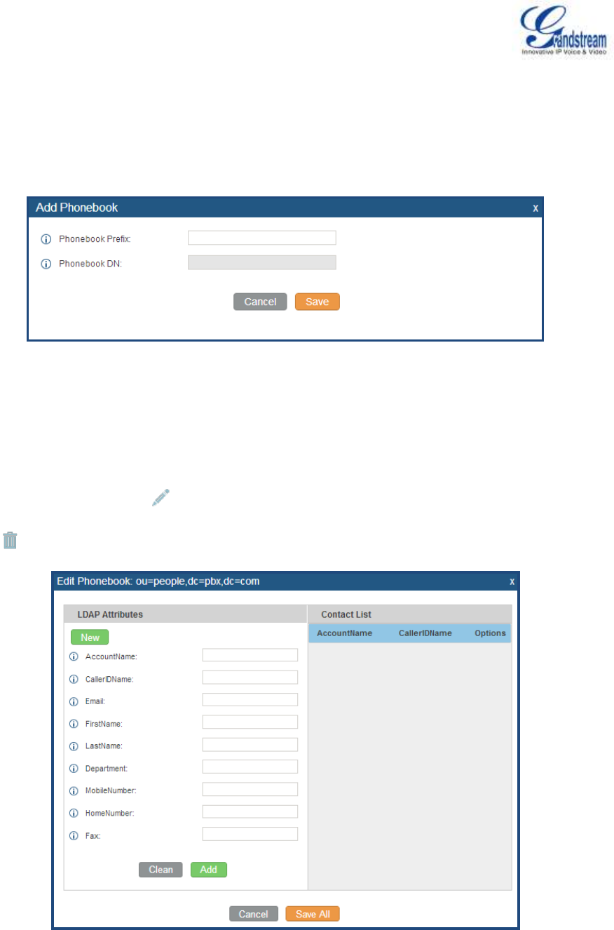
Firmware Version 1.0.0.5
UCM6510 IP PBX User Manual
Page 37 of 192
information will need to be modified via web GUI->PBX->Basic/Call Routes->Extensions first. The default
LDAP phonebook will then be updated automatically.
A new sibling phonebook of the default PBX phonebook can be added by clicking on "Add" under "LDAP
Phonebook" section.
Figure 10: Add LDAP Phonebook
Configure the "Phonebook Prefix" first. The "Phonebook DN" will be automatically filled in. For example, if
configuring "Phonebook Prefix" as "people", the "Phonebook DN" will be filled with
"ou=people,dc=pbx,dc=com".
Once added, users can select to edit the phonebook attributes and contact list (see figure below), or
select to delete the phonebook.
Figure 11: Edit LDAP Phonebook

Firmware Version 1.0.0.5
UCM6510 IP PBX User Manual
Page 38 of 192
LDAP CLIENT CONFIGURATIONS
The configuration on LDAP client is similar when you use other LDAP servers. Here we provide an example
on how to configure the LDAP client on the SIP end points to use the default PBX phonebook.
Assuming the server base dn is "dc=pbx,dc=com", configure the LDAP clients as follows (case
insensitive):
Base DN: dc=pbx,dc=com
Login DN: Please leave this field empty
Password: Please leave this field empty
Anonymous: Please enable this option
Filter: (|(CallerIDName=%)(AccountNumber=%))
Port: 389
To configure Grandstream IP phones as the LDAP client, please refer to the following example:
Server Address: The IP address or domain name of the UCM6510
Base DN: dc=pbx,dc=com
User Name: Please leave this field empty
Password: Please leave this field empty
LDAP Name Attribute: CallerIDName Email Department FirstName LastName
LDAP Number Attribute: AccountNumber MobileNumber HomeNumber Fax
LDAP Number Filter: (AccountNumber=%)
LDAP Name Filter: (CallerIDName=%)
LDAP Display Name: AccountNumber CallerIDName
LDAP Version: If existed, please select LDAP Version 3
Port: 389
The following figure shows the configuration information on a Grandstream GXP2200 to successfully use
the LDAP server as configured in Figure 7: LDAP Server Configurations.
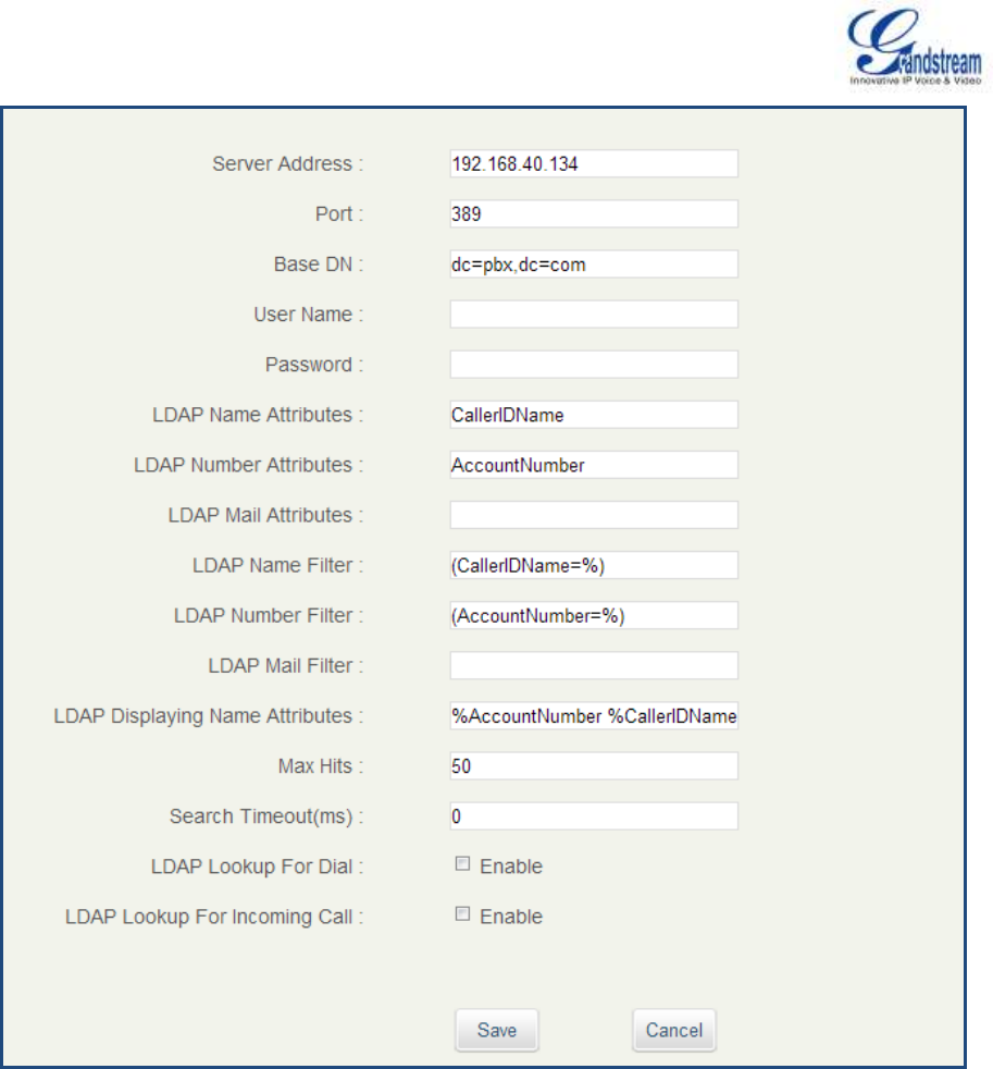
Firmware Version 1.0.0.5
UCM6510 IP PBX User Manual
Page 39 of 192
Figure 12: GXP2200 LDAP Phonebook Configuration
HTTP SERVER
The UCM6510 embedded web server responds to HTTP/HTTPS GET/POST requests. Embedded HTML
pages allow the users to configure the PBX through a web browser such as Microsoft IE, Mozilla Firefox and
Google Chrome. By default, the PBX can be accessed directly by typing IP address in the PC's web
browser (e.g., 192.168.40.50). It will then be automatically redirected to HTTPS using Port 8089 (e.g.,
https://192.168.40.50:8089). Users could also change the access protocol and port as preferred under web
GUI->Settings->HTTP Server.

Firmware Version 1.0.0.5
UCM6510 IP PBX User Manual
Page 40 of 192
Table 13: HTTP Server Settings
Redirect From Port 80
Enable or disable redirect from port 80. On the PBX, the default access
protocol is HTTPS and the default port number is 8089. When this option
is enabled, the access using HTTP with Port 80 will be redirected to
HTTPS with Port 8089. The default setting is "Enable".
Protocol Type
Select HTTP or HTTPS. The default setting is "HTTPS".
Port
Specify port number to access the HTTP server. The default port
number is 8089.
Once the change is saved, the web page will be redirected to the login page using the new URL. Enter the
username and password to login again.
EMAIL SETTINGS
The Email application on the UCM6510 can be used to send out alert event Emails, Fax (Fax-To-Email),
Voicemail (Voicemail-To-Email) and etc. The configuration parameters can be accessed via web
GUI->Settings->Email Settings.
Table 14: Email Settings
TLS Enable
Enable or disable TLS during transferring/submitting your Email to other
SMTP server. The default setting is "Yes".
Type
Select Email type.
MTA: Mail Transfer Agent. The Email will be sent from the
configured domain. When MTA is selected, there is no need to set
up SMTP server for it or no user login is required. However, the
Emails sent from MTA might be considered as spam by the target
SMTP server.
Client: Submit Emails to the SMTP server. A SMTP server is
required and users need login with correct credentials.
Domain
Specify the domain name to be used in the Email when using type
"MTA".
Server
Specify the SMTP server when using type "Client".
Username
Username is required when using type "Client". Normally it's the Email
address.
Password
Password to login for the above Username (Email address) is required
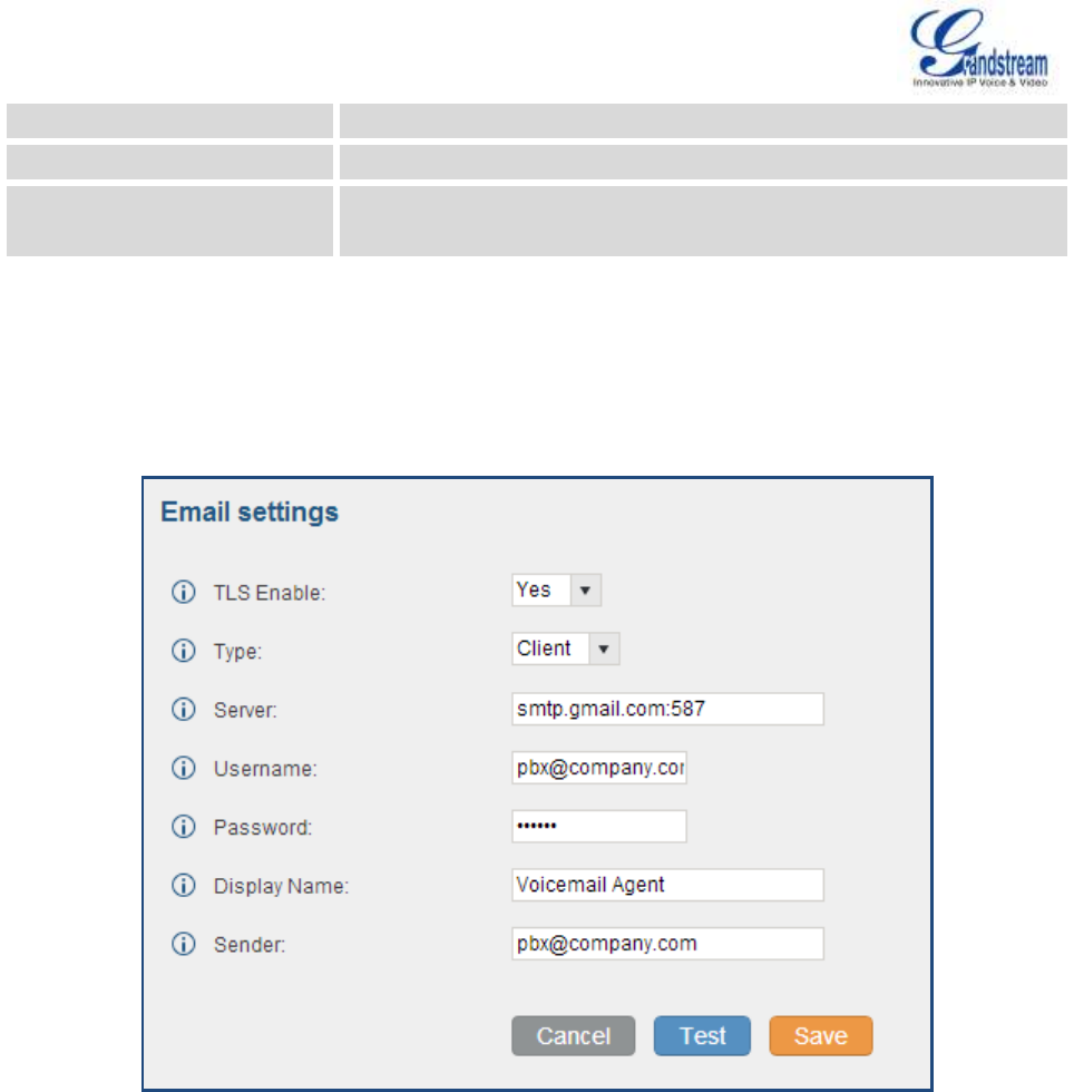
Firmware Version 1.0.0.5
UCM6510 IP PBX User Manual
Page 41 of 192
when using type "Client".
Display Name
Specify the display name in the FROM header in the Email.
Sender
Specify the sender's Email address.
For example, pbx@example.mycompany.com.
The following figure shows a sample Email settings on the UCM6510, assuming the Email is using
smtp.gmail.com as the SMTP server.
Figure 13: UCM6510 Email Settings
Once the configuration is finished, click on "Test". In the prompt, fill in a valid Email address to send a test
Email to verify the Email settings on the UCM6510.
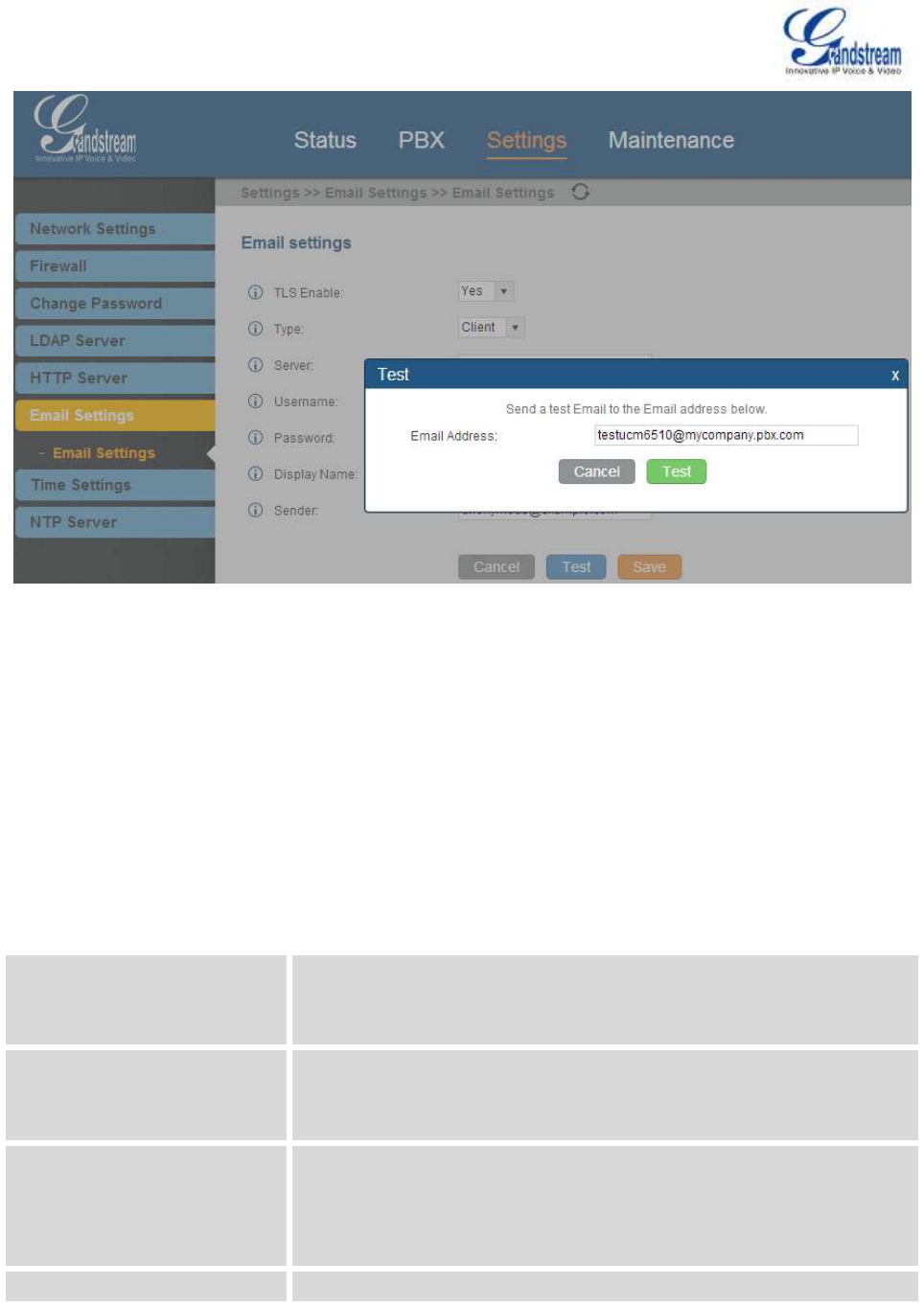
Firmware Version 1.0.0.5
UCM6510 IP PBX User Manual
Page 42 of 192
Figure 14: UCM6510 Email Settings: Send Test Email
TIME SETTINGS
The current system time on the UCM6510 is displayed on the upper right of the web page. It can also be
found under web GUI->Status->System Status->General.
To configure the UCM6510 to update time automatically, go to web GUI->Settings->Time Settings-> Auto
Time Updating.
Table 15: Auto Time Updating
Remote NTP Server
Specify the URL or IP address of the NTP server for the UCM6510 to
synchronize the date and time. The default NTP server is
ntp.ipvideotalk.com.
Enable DHCP Option 2
If set to "Yes", the UCM6510 is allowed to get provisioned for Time Zone
from DHCP Option 2 in the local server automatically. The default
setting is "Yes".
Enable DHCP Option 42
If set to "Yes", the UCM6510 is allowed to get provisioned for NTP
Server from DHCP Option 42 in the local server automatically. This will
override the manually configured NTP Server. The default setting is
"Yes".
Time Zone
Select the proper time zone option so the UCM6510 can display correct

Firmware Version 1.0.0.5
UCM6510 IP PBX User Manual
Page 43 of 192
time accordingly.
If "Self-Defined Tome Zone" is selected, please specify the time zone
parameters in "Self-Defined Time Zone" field as described in below
option.
Self-Defined Time Zone
If "Self-Defined Time Zone" is selected in "Time Zone" option, users will
need define their own time zone following the format below.
The syntax is: std offset dst [offset], start [/time], end [/time]
Default is set to: MTZ+6MDT+5,M4.1.0,M11.1.0
MTZ+6MDT+5
This indicates a time zone with 6 hours offset and 1 hour ahead for DST,
which is U.S central time. If it is positive (+), the local time zone is west
of the Prime Meridian (A.K.A: International or Greenwich Meridian); If it
is negative (-), the local time zone is east.
M4.1.0,M11.1.0
The 1st number indicates Month: 1, 2, 3..., 12 (for Jan, Feb, .., Dec).
The 2nd number indicates the nth iteration of the weekday: (1st Sunday,
3rd Tuesday…). Normally 1, 2, 3, 4 are used. If 5 is used, it means the
last iteration of the weekday.
The 3rd number indicates weekday: 0,1,2,..,6 ( for Sun, Mon,
Tues, ... ,Sat).
Therefore, this example is the DST which starts from the First Sunday of
April to the 1st Sunday of November.
To manually set the time on the UCM6510, go to web GUI->Settings->Time Settings->Set Time
Manually. The format is YYYY-MM-DD HH:MI:SS.
Figure 15: Set Time Manually

Firmware Version 1.0.0.5
UCM6510 IP PBX User Manual
Page 44 of 192
NTP SERVER
The UCM6510 can be used as a NTP server for the NTP clients to synchronize their time with. To configure
the UCM6510 as the NTP server, set "Enable NTP server" to "Yes" under web GUI->Settings->Time
Settings->NTP Server. On the client side, point the NTP server address to the UCM6510 IP address or
host name to use the UCM6510 as the NTP server.

Firmware Version 1.0.0.5
UCM6510 IP PBX User Manual
Page 45 of 192
PROVISIONING
OVERVIEW
Grandstream SIP Devices can be configured via web interface as well as via configuration file through
TFTP/HTTP/HTTPS download. All Grandstream SIP devices support a proprietary binary format
configuration file and XML format configuration file. The UCM6510 provides a Plug and Play mechanism to
auto-provision the Grandstream SIP devices in a zero configuration manner by generating XML config file
and having the phone to download it within LAN area. This allows users to finish the installation with ease
and start using the SIP devices in a managed way.
To provision a phone, three steps are involved, i.e., discovery, assignment and provisioning. The UCM6510
creates XML config file to the detected/assigned Grandstream device and accomplishes the following
configurations on the device after the provisioning:
A UCM6510 extension will be assigned and registered on the phone.
SIP-related network settings such as "NAT traversal" and "Use Random Port" are configured on the
phone.
Call feature settings such as "Public Mode", "Voicemail User ID", "Dial Plan" and "Auto Answer".
LDAP client configurations will be set up automatically on the phone to use the default LDAP directory
generated in the UCM6510 LDAP server.
This section explains how zero config works on the UCM6510. The settings for this feature can be accessed
via web GUI->PBX->Basic/Call Routes->Zero Config.
AUTO PROVISIONING
By default, the Zero Config feature is enabled on the UCM6510 for auto provisioning. Three methods of
auto provisioning are used.
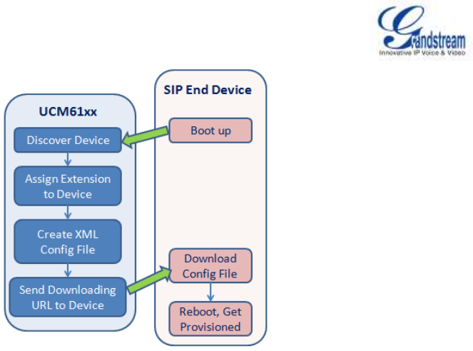
Firmware Version 1.0.0.5
UCM6510 IP PBX User Manual
Page 46 of 192
Figure 16: UCM6510 Zero Config
SIP SUBSCRIBE
When the phone boots up, it sends out SUBSCRIBE to a multicast IP address in the LAN. The
UCM6510 discovers it and then sends a NOTIFY with the XML config file URL in the message body.
The phone will then use the path to download the config file generated in the UCM6510 and reboot
again to take the new configuration.
DHCP OPTION 66
This method should be used only when the UCM6510 is set to "Route" mode under web
GUI->Settings->Network Settings->Basic Settings: Method. When the phone restarts (by default
DHCP Option 66 is turned on), it will send out a DHCP DISCOVER request. The UCM6510 receives it
and returns DHCP OFFER with the config server path URL in the Option 66, for example,
https://192.168.2.1:8089/zccgi/. The phone will then use the path to download the config file generated
in the UCM6510.
mDNS
When the phone boots up, it sends out mDNS query to get the TFTP server address. The UCM6510 will
respond with its own address. The phone will then send TFTP request to download the XML config file
from the UCM6510.
To start the auto provisioning process, under web GUI->PBX->Basic/Call Routes->Zero Config, click on
"Auto Provision Settings" and fill in the auto provision information.
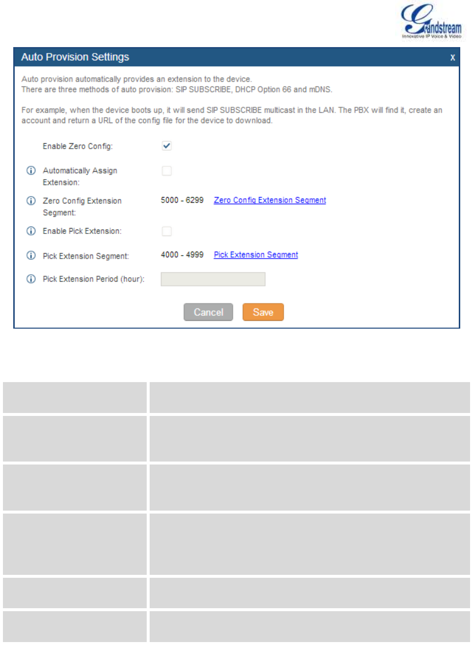
Firmware Version 1.0.0.5
UCM6510 IP PBX User Manual
Page 47 of 192
Figure 17: Auto Provision Settings
Table 16: Auto Provision Settings
Enable Zero Config
Enable or disable the zero config feature on the PBX. The default setting
is disabled.
Automatically Assign Extension
If enabled, when the device is discovered, the PBX will automatically
assign an extension within the range defined in "Zero Config Extension
Segment" to the device. The default setting is disabled.
Zero Config Extension
Segment
Click on the link "Zero Config Extension Segment" to specify the
extension range to be assigned if "Automatically Assign Extension" is
enabled. The default range is 5000-6299.
Enable Pick Extension
If enabled, the extension list will be sent out to the device after receiving
the device's request. This feature is for the GXP phones that support
selecting extension to be provisioned via phone's LCD. The default
setting is disabled.
Pick Extension Segment
Click on the link "Pick Extension Segment" to specify the extension list to
be sent to the device. The default range is 4000 to 4999.
Pick Extension Period (hour):
Specify the number of minutes to allow the phones being provisioned to
pick extensions.

Firmware Version 1.0.0.5
UCM6510 IP PBX User Manual
Page 48 of 192
Please make sure an extension is manually assigned to the phone or "Automatically Assign Extension" is
enabled during provisioning. After the configuration on the UCM6510 web GUI, click on "Save" and "Apply
Changes". Once the phone boots up and picks up the config file from the UCM6510, it will take the
configuration right away.
MANUAL PROVISIONING
DISCOVERY
Users could manually discover the device by specifying the IP address or scanning the entire LAN network.
Three methods are supported to scan the devices.
PING
ARP
SIP Message (NOTIFY)
Click on "Auto Discover", fill in the "Scan Method" and "Scan IP". The IP address segment will be
automatically filled in based on the network mask detected on the UCM6510. If users need scan the entire
network segment, enter 255 (for example, 192.168.40.255) instead of a specific IP address. Then click on
"Save" to start discovering the devices within the same network. To successfully discover the devices,
"Zero Config" needs to be enabled on the UCM6510 web GUI->PBX->Basic/Call Routes->Zero
Config->Auto Provisioning Settings.
Figure 18: Auto Discover
The following figure shows a list of discovered phones. The MAC address, IP Address, Extension (if
assigned), Version, Vendor, Model, Connection Status, Create Config, Options (Edit/Delete/Update) are
displayed in the list.
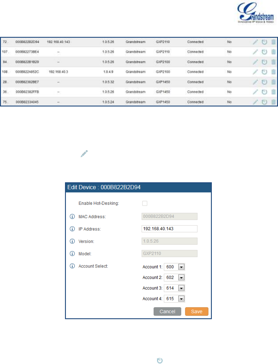
Firmware Version 1.0.0.5
UCM6510 IP PBX User Manual
Page 49 of 192
Figure 19: Discovered Devices
ASSIGNMENT
In the discovered list, click on to open the edit dialog to assign an extension or multiple extensions to
this device. Hot-Desking can also be enabled from this edit page.
Figure 20: Assign Extension To Device
After saving the edit dialog, the XML config file will be generated in the UCM6510. Reboot the phone or
trigger the phone to download the config file by clicking on icon for the entry in the zero config device
list.
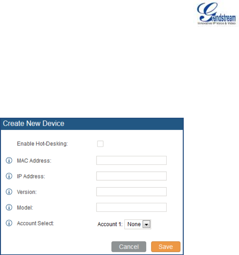
Firmware Version 1.0.0.5
UCM6510 IP PBX User Manual
Page 50 of 192
CREATE NEW DEVICE
Users could also directly create a new device and assign the extension before the device is discovered by
the UCM6510. Once the device is plugged in, it can then be discovered and provisioned by the UCM6510.
Click on "Create New Device" and the following dialog will show. Enabled Hot-Desking (optional), fill in the
MAC address (required), IP address (optional), Version (optional), Model (optional) and the extension
(required) to assign to the device. Click on "Save" to add the device to the provision list.
Figure 21: Create New Device
PROVISIONING
After the successful discovery and assignment configuration on the UCM6510, the device will start
downloading the config file and take the new configuration with the extension registered.

Firmware Version 1.0.0.5
UCM6510 IP PBX User Manual
Page 51 of 192
EXTENSIONS
CREATE NEW USER
CREATE NEW SIP EXTENSION
To manually create new SIP user, go to web GUI->PBX->Basic/Call Routes->Extensions. Click on
"Create New User"->"Create New SIP Extension" and a new dialog window will show for users to fill in the
extension information. The configuration parameters are as follows.
Table 17: SIP Extension Configuration Parameters
General
Extension
The extension number associated with the user.
CallerID Number
Configure the CallerID Number that would be applied for outbound calls
from this user.
Note:
The ability to manipulate your outbound Caller ID may be limited by your
VoIP provider.
Permission
Assign permission level to the user. The available permissions are
"Internal", "Local", "National" and "International" from the lowest level to
the highest level. The default setting is "Internal".
Note:
Users need to have the same level as or higher level than an outbound
rule's privilege in order to make outbound calls using this rule.
SIP/IAX Password
Configure the password for the user. A random secure password will be
automatically generated. It is recommended to use this password for
security purpose.
Enable Voicemail
Enable voicemail for the user. The default setting is "Yes".
Voicemail Password
Configure voicemail password (digits only) for the user to access the
voicemail box. A random numeric password is automatically generated.
It is recommended to use the random generated password for security
purpose.
Call Forward Unconditional
Configure the Call Forward Unconditional target number. If not
configured, the Call Forward Unconditional feature is deactivated. The
default setting is deactivated.

Firmware Version 1.0.0.5
UCM6510 IP PBX User Manual
Page 52 of 192
Call Forward No Answer
Configure the Call Forward No Answer target number. If not configured,
the Call Forward No Answer feature is deactivated. The default setting is
deactivated.
Call Forward Busy
Configure the Call Forward Busy target number. If not configured, the
Call Forward Busy feature is deactivated. The default setting is
deactivated.
Ring Timeout
Configure the number of seconds to ring the user before the call is
forwarded to voicemail (voicemail is enabled) or hang up (voicemail is
disabled). If not specified, the default ring timeout is 60 seconds on the
UCM6510, which can be configured in the global ring timeout setting
under web GUI->Internal Options->IVR Prompt: General Preference.
The valid range is between 5 seconds and 600 seconds.
Note:
If the end point also has a ring timeout configured, the actual ring
timeout used is the shortest time set by either device.
Auto Record
Enable automatic recording for the calls using this extension. The
default setting is disabled. The recording files will be saved in external
storage if plugged in and can be accessed under web
GUI->CDR->Recording Files.
Skip Voicemail Password
Verification
When user dials voicemail code, the password verification IVR is
skipped. If enabled, this would allow one-button voicemail access. By
default this option is disabled.
Support Hot-Desking Mode
If enabled, SIP Password will accept only alphabet characters and digits;
AuthID will be changed to the same as Extension
User Settings
First Name
Configure the first name of the user. The first name can contain
characters, letters, digits and _.
Last Name
Configure the last name of the user. The last name can contain
characters, letters, digits and _.
Email Address
Fill in the Email address for the user. Voicemail will be sent to this Email
address.
Language
Select the voice prompt language to be used for this extension. The
default setting is "Default" which is the selected voice prompt language
under web GUI->PBX->Internal Options->Language. The dropdown
list shows all the current available voice prompt languages on the
UCM6510. To add more languages in the list, please download voice
prompt package by selecting "Check Prompt List" under web

Firmware Version 1.0.0.5
UCM6510 IP PBX User Manual
Page 53 of 192
GUI->PBX->Internal Options->Language.
SIP Settings
NAT
Use NAT when the UCM6510 is on a public IP communicating with
devices hidden behind NAT (e.g., broadband router). If there is one-way
audio issue, usually it's related to NAT configuration or Firewall's support
of SIP and RTP ports. The default setting is enabled.
Can Reinvite
By default, the UCM6510 will route the media steams from SIP
endpoints through itself. If enabled, the PBX will attempt to negotiate
with the endpoints to route the media stream directly. It is not always
possible for the UCM6510 to negotiate endpoint-to-endpoint media
routing. The default setting is "No".
DTMF Mode
Select DTMF mode for the user to send DTMF. The default setting is
"RFC2833". If "Info" is selected, SIP INFO message will be used. If
"Inband" is selected, 64-kbit PCMU and PCMA are required. When
"Auto" is selected, RFC2833 will be used if offered, otherwise "Inband"
will be used.
Insecure
Port: Allow peers matching by IP address without matching port
number.
Very: Allow peers matching by IP address without matching port
number. Also, authentication of incoming INVITE messages is not
required.
No: Normal IP-based peers matching and authentication of
incoming INVITE.
The default setting is "Port".
Enable Keep-alive
If enabled, empty SDP packet will be sent to the SIP server periodically
to keep the NAT port open. The default setting is "Yes".
Keep-alive Frequency
Configure the Keep-alive interval (in seconds) to check if the host is up.
The default setting is 60 seconds.
Auth ID
Configure the authentication ID for the user. If not configured, the
CallerID number
Other Settings
SRTP
Enable SRTP for the call. The default setting is disabled.
Fax Detection
Enable to detect Fax signal from the user/trunk during the call and send
the received Fax to the Email address configured for this extension. If no
Email address can be found for the user, send the received Fax to the
default Email address in Fax setting page under UCM6510 web
GUI->PBX->Internal Options->Fax/T.38.

Firmware Version 1.0.0.5
UCM6510 IP PBX User Manual
Page 54 of 192
Note:
If enabled, Fax Pass-through cannot be used.
Strategy
This option controls how the extension can be used on devices within
different types of network.
Allow All
Device in any network can register this extension.
Local Subnet Only
Only the user in specific subnet can register this extension. Up to
three subnet addresses can be specified.
A Specific IP Address
Only the device on the specific IP address can register this
extension.
The default setting is "Allow All".
Skip Trunk Auth
If enabled, users will not need enter the "PIN Set" required by the
outbound rule to make outbound calls. The default setting is "No".
Codec Preference
Select audio and video codec for the extension. The available codecs
are: PCMU, PCMA, GSM, AAL2-G.726-32, G,726, G.722, G.729,
G.723, ILBC, ADPCM, H.264, H.263 and H.263p.
CREATE NEW IAX EXTENSION
To manually create new IAX user, go to web GUI->PBX->Basic/Call Routes->Extensions. Click on
"Create New User"->"Create New IAX Extension" and a new dialog window will show for users to fill in the
extension information. The configuration parameters are as follows.
Table 18: IAX Extension Configuration Parameters
General
Extension
The extension number associated with the user.
CallerID Number
Configure the CallerID Number that would be applied for outbound calls
from this user.
Note:
The ability to manipulate your outbound Caller ID may be limited by your
VoIP provider.
Permission
Assign permission level to the user. The available permissions are

Firmware Version 1.0.0.5
UCM6510 IP PBX User Manual
Page 55 of 192
"Internal", "Local", "National" and "International" from the lowest level to
the highest level. The default setting is "Internal".
Note:
Users need to have the same level as or higher level than an outbound
rule's privilege in order to make outbound calls using this rule.
SIP/IAX Password
Configure the password for the user. A random secure password will be
automatically generated. It is recommended to use this password for
security purpose.
Enable Voicemail
Enable voicemail for the user. The default setting is "Yes".
Voicemail Password
Configure voicemail password (digits only) for the user to access the
voicemail box. A random numeric password is automatically generated.
It is recommended to use the random generated password for security
purpose.
Call Forward Unconditional
Configure the Call Forward Unconditional target number. If not
configured, the Call Forward Unconditional feature is deactivated. The
default setting is deactivated.
Call Forward No Answer
Configure the Call Forward No Answer target number. If not configured,
the Call Forward No Answer feature is deactivated. The default setting is
deactivated.
Call Forward Busy
Configure the Call Forward Busy target number. If not configured, the
Call Forward Busy feature is deactivated. The default setting is
deactivated.
Ring Timeout
Configure the number of seconds to ring the user before the call is
forwarded to voicemail (voicemail is enabled) or hang up (voicemail is
disabled). If not specified, the default ring timeout is 60 seconds on the
UCM6510, which can be configured in the global ring timeout setting
under web GUI->Internal Options->IVR Prompt: General Preference.
The valid range is between 5 seconds and 600 seconds.
Note:
If the end point also has a ring timeout configured, the actual ring
timeout used is the shortest time set by either device.
Auto Record
Enable automatic recording for the calls using this extension. The
default setting is disabled. The recording files will be saved in external
storage if plugged in and can be accessed under web
GUI->CDR->Recording Files.
Skip Voicemail Password
When user dials voicemail code, the password verification IVR is

Firmware Version 1.0.0.5
UCM6510 IP PBX User Manual
Page 56 of 192
Verification
skipped. If enabled, this would allow one-button voicemail access. By
default this option is disabled.
User Settings
First Name
Configure the first name of the user. The first name can contain
characters, letters, digits and _.
Last Name
Configure the last name of the user. The last name can contain
characters, letters, digits and _.
Email Address
Fill in the Email address for the user. Voicemail will be sent to this Email
address.
Language
Select the voice prompt language to be used for this extension. The
default setting is "Default" which is the selected voice prompt language
under web GUI->PBX->Internal Options->Language. The dropdown
list shows all the current available voice prompt languages on the
UCM6510. To add more languages in the list, please download voice
prompt package by selecting "Check Prompt List" under web
GUI->PBX->Internal Options->Language.
IAX Settings
Max Number of Calls
Configure the maximum number of calls allowed for each remote IP
address.
Require Call Token
Configure to enable/disable requiring call token. If set to "Auto", it might
lock out users who depend on backward compatibility when peer
authentication credentials are shared between physical endpoints. The
default setting is "Yes".
Other Settings
SRTP
Enable SRTP for the call. The default setting is disabled.
Fax Detection
Enable to detect Fax signal from the user/trunk during the call and send
the received Fax to the Email address configured for this extension. If no
Email address can be found for the user, send the received Fax to the
default Email address in Fax setting page under web
GUI->PBX->Internal Options->Fax/T.38.
Note:
If enabled, Fax Pass-through cannot be used.
Strategy
This option controls how the extension can be used on devices within
different types of network.
Allow All
Device in any network can register this extension.
Local Subnet Only

Firmware Version 1.0.0.5
UCM6510 IP PBX User Manual
Page 57 of 192
Only the user in specific subnet can register this extension. Up to
three subnet addresses can be specified.
A Specific IP Address
Only the device on the specific IP address can register this
extension.
The default setting is "Allow All".
Skip Trunk Auth
If enabled, users will not need enter the "PIN Set" required by the
outbound rule to make outbound calls. The default setting is "No".
Codec Preference
Select audio and video codec for the extension. The available codecs
are: PCMU, PCMA, GSM, AAL2-G.726-32, G,726, G.722, G.729,
G.723, ILBC, ADPCM, H.264, H.263 and H.263p.
CREATE NEW FXS EXTENSION
To manually create new FXS user, go to web GUI->PBX->Basic/Call Routes->Extensions. Click on
"Create New User"->"Create New FXS Extension" and a new dialog window will show for users to fill in the
extension information. The configuration parameters are as follows.
Table 19: FXS Extension Configuration Parameters
General
Extension
The extension number associated with the user.
Analog Station
Select the FXS port to be assigned for this extension.
CallerID Number
Configure the CallerID Number that would be applied for outbound calls
from this user.
Note:
The ability to manipulate your outbound Caller ID may be limited by your
VoIP provider.
Permission
Assign permission level to the user. The available permissions are
"Internal", "Local", "National" and "International" from the lowest level to
the highest level. The default setting is "Internal".
Note:
Users need to have the same level as or higher level than an outbound
rule's privilege in order to make outbound calls using this rule.
Enable Voicemail
Enable voicemail for the user. The default setting is "Yes".

Firmware Version 1.0.0.5
UCM6510 IP PBX User Manual
Page 58 of 192
Voicemail Password
Configure voicemail password (digits only) for the user to access the
voicemail box. A random numeric password is automatically generated.
It is recommended to use the random generated password for security
purpose.
Call Forward Unconditional
Configure the Call Forward Unconditional target number. If not
configured, the Call Forward Unconditional feature is deactivated. The
default setting is deactivated.
Call Forward No Answer
Configure the Call Forward No Answer target number. If not configured,
the Call Forward No Answer feature is deactivated. The default setting is
deactivated.
Call Forward Busy
Configure the Call Forward Busy target number. If not configured, the
Call Forward Busy feature is deactivated. The default setting is
deactivated.
Ring Timeout
Configure the number of seconds to ring the user before the call is
forwarded to voicemail (voicemail is enabled) or hang up (voicemail is
disabled). If not specified, the default ring timeout is 60 seconds on the
UCM6510, which can be configured in the global ring timeout setting
under web GUI->Internal Options->IVR Prompt: General Preference.
The valid range is between 5 seconds and 600 seconds.
Note:
If the end point also has a ring timeout configured, the actual ring
timeout used is the shortest time set by either device.
Auto Record
Enable automatic recording for the calls using this extension. The
default setting is disabled. The recording files will be saved in external
storage if plugged in and can be accessed under web
GUI->CDR->Recording Files.
Skip Voicemail Password
Verification
When user dials voicemail code, the password verification IVR is
skipped. If enabled, this would allow one-button voicemail access. By
default this option is disabled.
User Settings
First Name
Configure the first name of the user. The first name can contain
characters, letters, digits and _.
Last Name
Configure the last name of the user. The last name can contain
characters, letters, digits and _.
Email Address
Fill in the Email address for the user. Voicemail will be sent to this Email
address.
Language
Select the voice prompt language to be used for this extension. The

Firmware Version 1.0.0.5
UCM6510 IP PBX User Manual
Page 59 of 192
default setting is "Default" which is the selected voice prompt language
under web GUI->PBX->Internal Options->Language. The dropdown
list shows all the current available voice prompt languages on the
UCM6510. To add more languages in the list, please download voice
prompt package by selecting "Check Prompt List" under web
GUI->PBX->Internal Options->Language.
Analog Settings
Call Waiting
Configure to enable/disable call waiting feature. The default setting is
"No".
User # as SEND
If configured, the # key can be used as SNED key after dialing the
number on the analog phone. The default setting is "Yes".
RX Gain
Configure the RX gain for the receiving channel of analog FXS port. The
valid range is -30dB to +6dB. The default setting is 0.
TX Gain
Configure the TX gain for the transmitting channel of analog FXS port.
The valid range is -30dB to +6dB. The default setting is 0.
MIN RX Flash
Configure the minimum period of time (in milliseconds) that the
hook-flash must remain unpressed for the PBX to consider the event as
a valid flash event. The valid range is 30ms to 1000ms. The default
setting is 200ms.
MAX RX Flash
Configure the maximum period of time (in milliseconds) that the
hook-flash must remain unpressed for the PBX to consider the event as
a valid flash event. The minimum period of time is 256ms and it can't be
modified. The default setting is 1250ms.
Enable Polarity Reversal
If enabled, a polarity reversal will be marked as received when an
outgoing call is answered by the remote party. For some countries, a
polarity reversal is used for signaling the disconnection of a phone line
and the call will be considered as hangup on a polarity reversal. The
default setting is "Yes".
Echo Cancellation
Specify "ON", "OFF" or a value (the power of 2) from 32 to 1024 as the
number of taps of cancellation.
Note:
When configuring the number of taps, the number 256 is not translated
into 256ms of echo cancellation. Instead, 256 taps means 256/8 = 32
ms. The default setting is "ON", which is 128 taps.
3-Way Calling
Configure to enable/disable 3-way calling feature on the user. The
default setting is enabled.

Firmware Version 1.0.0.5
UCM6510 IP PBX User Manual
Page 60 of 192
Send CallerID After
Configure the number of rings before sending CID. The default setting is
1.
Other Settings
Fax Detection
Enable to detect Fax signal from the user/trunk during the call and send
the received Fax to the Email address configured for this extension. If no
Email address can be found for the user, send the received Fax to the
default Email address in Fax setting page under web
GUI->PBX->Internal Options->Fax/T.38.
Note:
If enabled, Fax Pass-through cannot be used.
Skip Trunk Auth
If enabled, users will not need enter the "PIN Set" required by the
outbound rule to make outbound calls. The default setting is "No".
BATCH ADD EXTENSIONS
BATCH ADD SIP EXTENSIONS
Under web GUI->PBX->Basic/Call Routes->Extensions, click on "Batch Add Extensions"->"Batch Add
SIP Extensions".
Table 20: Batch Add SIP Extension Parameters
General
Start Extension
Configure the starting extension number of the batch of extensions to be
added.
Create Number
Specify the number of extensions to be added. The default setting is 5.
Permission
Assign permission level to the user. The available permissions are
"Internal", "Local", "National" and "International" from the lowest level to
the highest level. The default setting is "Internal".
Note:
Users need to have the same level as or higher level than an outbound
rule's privilege in order to make outbound calls from this rule.
Enable Voicemail
Enable Voicemail for the user. The default setting is "Yes".
SIP/IAX Password
Configure the SIP/IAX password for the users. Three options are
available to create password for the batch of extensions.

Firmware Version 1.0.0.5
UCM6510 IP PBX User Manual
Page 61 of 192
User Random Password.
A random secure password will be automatically generated. It is
recommended to use this password for security purpose.
Use Extension as Password.
Enter a password to be used on all the extensions in the batch.
Voicemail Password
Configure Voicemail password (digits only) for the users.
User Random Password.
A random password in digits will be automatically generated. It is
recommended to use this password for security purpose.
Use Extension as Password.
Enter a password to be used on all the extensions in the batch.
Ring Timeout
Configure the number of seconds to ring the user before the call is
forwarded to voicemail (voicemail is enabled) or hang up (voicemail is
disabled). If not specified, the default ring timeout is 60 seconds on the
UCM6510, which can be configured in the global ring timeout setting
under web GUI->Internal Options->IVR Prompt: General Preference.
The valid range is between 5 seconds and 600 seconds.
Note:
If the end point also has a ring timeout configured, the actual ring
timeout used is the shortest time set by either device.
Auto Record
Enable automatic recording for the calls using this extension. The
default setting is disabled. The recording files will be saved in external
storage if plugged in and can be accessed under web
GUI->CDR->Recording Files.
Skip Voicemail Password
Verification
When user dials voicemail code, the password verification IVR is
skipped. If enabled, this would allow one-button voicemail access. By
default this option is disabled.
SIP Settings
NAT
Use NAT when the PBX is on a public IP communicating with devices
hidden behind NAT (e.g., broadband router). If there is one-way audio
issue, usually it's related to NAT configuration or Firewall's support of
SIP and RTP ports. The default setting is enabled.
Can Reinvite
By default, the PBX will route the media steams from SIP endpoints
through itself. If enabled, the PBX will attempt to negotiate with the
endpoints to route the media stream directly. It is not always possible for
the PBX to negotiate endpoint-to-endpoint media routing. The default
setting is "No".
DTMF Mode
Select DTMF mode for the user to send DTMF. The default setting is

Firmware Version 1.0.0.5
UCM6510 IP PBX User Manual
Page 62 of 192
"RFC2833". If "Info" is selected, SIP INFO message will be used. If
"Inband" is selected, 64-kbit codec PCMU and PCMA are required.
When "Auto" is selected, RFC2833 will be used if offered, otherwise
"Inband" will be used.
Insecure
Port: Allow peers matching by IP address without matching port
number.
Very: Allow peers matching by IP address without matching port
number. Also, authentication of incoming INVITE messages is not
required.
No: Normal IP-based peers matching and authentication of
incoming INVITE.
The default setting is "Port".
Enable Keep-alive
If enabled, empty SDP packet will be sent to the SIP server periodically
to keep the NAT port open. The default setting is "Yes".
Keep-alive Frequency
Configure the number of seconds for the host to be up for Keep-alive.
The default setting is 60 seconds.
Other Settings
SRTP
Enable SRTP for the call. The default setting is "No".
Fax Detection
Enable to detect Fax signal from the user/trunk during the call and send
the received Fax to the Email address configured for this extension. If no
Email address can be found for the user, send the received Fax to the
default Email address in Fax setting page under web
GUI->PBX->Internal Options->Fax/T.38.
Note:
If enabled, Fax Pass-through cannot be used.
Strategy
This option controls how the extension can be used on devices within
different types of network.
Allow All
Device in any network can register this extension.
Local Subnet Only
Only the user in specific subnet can register this extension. Up to
three subnet addresses can be specified.
A Specific IP Address.
Only the device on the specific IP address can register this
extension.
The default setting is "Allow All".

Firmware Version 1.0.0.5
UCM6510 IP PBX User Manual
Page 63 of 192
Skip Trunk Auth
If enabled, users will not need enter the "PIN Set" required by the
outbound rule to make outbound calls. The default setting is "No".
Codec Preference
Select audio and video codec for the extension. The available codecs
are: PCMU, PCMA, GSM, AAL2-G.726-32, G.722, G.729, G.723, ILBC,
ADPCM, LPC10, H.264, H.263 and H.263p.
BATCH ADD IAX EXTENSIONS
Under web GUI->PBX->Basic/Call Routes->Extensions, click on "Batch Add Extensions"->"Batch Add
IAX Extensions".
Table 21: Batch Add IAX Extension Parameters
General
Start Extension
Configure the starting extension number of the batch of extensions to be
added.
Create Number
Specify the number of extensions to be added. The default setting is 5.
Permission
Assign permission level to the user. The available permissions are
"Internal", "Local", "National" and "International" from the lowest level to
the highest level. The default setting is "Internal".
Note:
Users need to have the same level as or higher level than an outbound
rule's privilege in order to make outbound calls from this rule.
Enable Voicemail
Enable Voicemail for the user. The default setting is "Yes".
SIP/IAX Password
Configure the SIP/IAX password for the users. Three options are
available to create password for the batch of extensions.
User Random Password.
A random secure password will be automatically generated. It is
recommended to use this password for security purpose.
Use Extension as Password.
Enter a password to be used on all the extensions in the batch.
Voicemail Password
Configure Voicemail password (digits only) for the users.
User Random Password.
A random password in digits will be automatically generated. It is
recommended to use this password for security purpose.
Use Extension as Password.
Enter a password to be used on all the extensions in the batch.

Firmware Version 1.0.0.5
UCM6510 IP PBX User Manual
Page 64 of 192
Ring Timeout
Configure the number of seconds to ring the user before the call is
forwarded to voicemail (voicemail is enabled) or hang up (voicemail is
disabled). If not specified, the default ring timeout is 60 seconds on the
UCM6510, which can be configured in the global ring timeout setting
under web GUI->Internal Options->IVR Prompt: General Preference.
The valid range is between 5 seconds and 600 seconds.
Note:
If the end point also has a ring timeout configured, the actual ring
timeout used is the shortest time set by either device.
Auto Record
Enable automatic recording for the calls using this extension. The
default setting is disabled. The recording files will be saved in external
storage if plugged in and can be accessed under web
GUI->CDR->Recording Files.
Skip Voicemail Password
Verification
When user dials voicemail code, the password verification IVR is
skipped. If enabled, this would allow one-button voicemail access. By
default this option is disabled.
IAX Settings
Max Number of Calls
Configure the maximum number of calls allowed for each remote IP
address.
Require Call Token
Configure to enable/disable requiring call token. If set to "Auto", it might
lock out users who depend on backward compatibility when peer
authentication credentials are shared between physical endpoints. The
default setting is "Yes".
Other Settings
SRTP
Enable SRTP for the call. The default setting is "No".
Fax Detection
Enable to detect Fax signal from the user/trunk during the call and send
the received Fax to the Email address configured for this extension. If no
Email address can be found for the user, send the received Fax to the
default Email address in Fax setting page under web
GUI->PBX->Internal Options->Fax/T.38.
Note:
If enabled, Fax Pass-through cannot be used.
Strategy
This option controls how the extension can be used on devices within
different types of network.
Allow All
Device in any network can register this extension.

Firmware Version 1.0.0.5
UCM6510 IP PBX User Manual
Page 65 of 192
Local Subnet Only
Only the user in specific subnet can register this extension. Up to
three subnet addresses can be specified.
A Specific IP Address.
Only the device on the specific IP address can register this
extension.
The default setting is "Allow All".
Skip Trunk Auth
If enabled, users will not need enter the "PIN Set" required by the
outbound rule to make outbound calls. The default setting is "No".
Codec Preference
Select audio and video codec for the extension. The available codecs
are: PCMU, PCMA, GSM, AAL2-G.726-32, G.722, G.729, G.723, ILBC,
ADPCM, LPC10, H.264, H.263 and H.263p.
EDIT EXTENSION
All the UCM6510 extensions are listed under web GUI->PBX->Basic/Call Routes->Extensions, with
status, Extension, CallerID Name, Technology (SIP, IAX and FXS), IP and Port. Each extension has a
checkbox for users to "Modify Selected Extensions" or "Delete Selected Extensions". Also, options "Edit"
, "Reboot" and "Delete" are available per extension.
Status
Users can see the following icon for each extension to indicate the SIP status.
Green: Free
Blue: Ringing
Yellow: In Use
Grey: Unavailable
Edit single extension
Click on to start editing the extension parameters.
Reboot the user

Firmware Version 1.0.0.5
UCM6510 IP PBX User Manual
Page 66 of 192
Click on to send NOTIFY reboot event to the device which has an UCM6510 extension already
registered. To successfully reboot the user, "Zero Config" needs to be enabled on the UCM6510 web
GUI->PBX->Basic/Call Routes->Zero Config->Auto Provisioning Settings.
Delete single extension
Click on to delete the extension. Or select the checkbox of the extension and then click on "Delete
Selected Extensions".
Modify selected extensions
Select the checkbox for the extension(s). Then click on "Modify Selected Extensions" to edit the
extensions in a batch.
Delete selected extensions
Select the checkbox for the extension(s). Then click on "Delete Selected Extensions" to delete the
extension(s).
EXPORT EXTENSIONS
The extensions configured on the UCM6510 can be exported to csv format file with selected technology
"SIP", "IAX" or "FXS". Click on "Export Extensions" button and select technology in the prompt.
Figure 22: Export Extensions
The exported csv file can also serve as a template for users to fill in desired extension information to be
imported to the UCM6510.
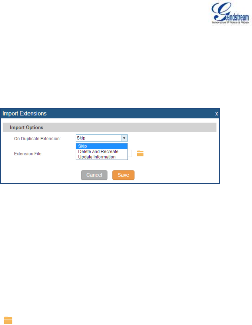
Firmware Version 1.0.0.5
UCM6510 IP PBX User Manual
Page 67 of 192
IMPORT EXTENSIONS
The capability to import extensions to the UCM6510 provides users flexibility to batch add extensions with
similar or different configurations quickly.
1. Export extension csv file from the UCM6510 by clicking on "Export Extensions" button.
2. Fill up the extension information you would like in the exported csv template.
3. Click on "Import Extensions" button. The following dialog will be prompted.
Figure 23: Export Extensions
4. Select the option in "On Duplicate Extension" to define how the duplicate extension(s) in the imported
csv file should be treated by the PBX.
Skip: Duplicate extensions in the csv file will be skipped. The PBX will keep the current extension
information as previously configured without change.
Delete and Recreate: The current extension previously configured will be deleted and the duplicate
extension in the csv file will be loaded to the PBX.
Update Information: The current extension previously configured in the PBX will be kept. However,
if the duplicate extension in the csv file has different configuration for any options, it will override the
configuration for those options in the extension.
5. Click on to select csv file from local directory in the PC.
6. Click on "Save" to import the csv file.
7. Click on "Apply Changes" to apply the imported file on the UCM6510.

Firmware Version 1.0.0.5
UCM6510 IP PBX User Manual
Page 68 of 192
ANALOG TRUNKS
To set up analog trunk on the UCM6510:
Go to web GUI->PBX->Basic/Call Routes->Analog Trunks to add and edit analog trunks.
Go to web GUI->PBX->Ports Config->Analog Hardware to configure analog hardware settings.
ANALOG TRUNKS CONFIGURATION
Go to web GUI->PBX->Basic/Call Routes->Analog Trunks to add and edit analog trunks.
Click on "Create New Analog Trunk" to add a new analog trunk.
Click on to edit the analog trunk.
Click on to delete the analog trunk.
The analog trunk options are listed in the table below.
Table 22: Analog Trunk Configuration Parameters
Channels
Select the channel for the analog trunk.
Trunk Name
Specify a unique label to identify the trunk when listed in outbound rules,
incoming rules and etc.
Advanced Options
Enable Polarity Reversal
If enabled, a polarity reversal will be marked as received when an
outgoing call is answered by the remote party. For some countries, a
polarity reversal is used for signaling the disconnection of a phone line
and the call will be considered as "hangup" on a polarity reversal. The
default setting is "No".
Polarity on Answer Delay
When FXO port answers the call, FXS may send a Polarity Reversal. If
this interval is shorter than the value of "Polarity on Answer Delay", the
Polarity Reversal will be ignored. Otherwise, the FXO will onhook to
disconnect the call. The default setting is 600ms.
Current Disconnect Threshold
(ms)
This is the periodic time (in ms) that the UCM6510 will use to check on a
voltage drop in the line. The default setting is 200. The valid range is 50
to 3000.

Firmware Version 1.0.0.5
UCM6510 IP PBX User Manual
Page 69 of 192
Ring Timeout
Configure the ring timeout (in ms). Trunk (FXO) devices must have a
timeout to determine if there was a hangup before the line is answered.
This value can be used to configure how long it takes before the
UCM6510 considers a non-ringing line with hangup activity. The default
setting is 8000.
RX Gain
Configure the RX gain for the receiving channel of analog FXO port. The
valid range is from -13.5 (dB) to + 12.0 (dB). The default setting is 0.
TX Gain
Configure the TX gain for the transmitting channel of analog FXO port.
The valid range is from -13.5 (dB) to + 12.0 (dB). The default setting is 0.
Use CallerID
Configure to enable CallerID detection. The default setting is "Yes".
Fax Detection
Enable to detect Fax signal from the trunk during the call and send the
received Fax to the default Email address in Fax setting page under web
GUI->PBX->Internal Options->Fax/T.38. The default setting is "No".
Note:
If enabled, Fax Pass-through cannot be used.
Caller ID Scheme
Select the Caller ID scheme for this trunk. The default setting is
"Bellcore/Telcordia".
Auto Record
Enable automatic recording for the calls using this trunk. The default
setting is disabled. The recording files are saved in external storage
device if plugged in and can be accessed under web
GUI->CDR->Recording Files.
Tone Settings
Busy Detection
Busy Detection is used to detect far end hangup or for detecting busy
signal. The default setting is "Yes".
Busy Tone Count
If "Busy Detection" is enabled, users can specify the number of busy
tones to be played before hanging up. The default setting is 2. Better
results might be achieved if set to 4, 6 or even 8. Please note that the
higher the number is, the more time is needed to hangup the channel.
However, this might lower the probability to get random hangup.
Congestion Detection
Congestion detection is used to detect far end congestion signal. The
default setting is "Yes".
Congestion Count
If "Congestion Detection" is enabled, users can specify the number of
congestion tones to wait for. The default setting is 2.
Tone Country
Select the country for tone settings. If "Custom" is selected, users could
manually configure the values for Busy Tone and Congestion Tone. The
default setting is "United States of America (USA)".
Busy Tone
Syntax:

Firmware Version 1.0.0.5
UCM6510 IP PBX User Manual
Page 70 of 192
f1=val[@level][,f2=val[@level]],c=on1/off1[-on2/off2[-on3/off3]];
Frequencies are in Hz and cadence on and off are in ms.
Frequencies Range: [0, 4000)
Busy Level Range: (-300, 0)
Cadence Range: [0, 16383].
Select Tone Country "Custom" to manually configure Busy Tone value.
Default value:
f1=480@-50,f2=620@-50,c=500/500
Congestion Tone
Syntax:
f1=val[@level][,f2=val[@level]],c=on1/off1[-on2/off2[-on3/off3]];
Frequencies are in Hz and cadence on and off are in ms.
Frequencies Range: [0, 4000)
Busy Level Range: (-300, 0)
Cadence Range: [0, 16383].
Select Tone Country "Custom" to manually configure Busy Tone value.
Default value:
f1=480@-50,f2=620@-50,c=250/250
PSTN Detection
Click on "Detect" to detect the busy tone, Polarity Reversal and Current
Disconnect by PSTN. Before the detecting, please make sure there are
more than one channel configured and working properly. If the detection
has busy tone, the "Tone Country" option will be set as "Custom".
PSTN DETECTION
The UCM6510 provides PSTN detection function to help users detect the busy tone, Polarity Reversal and
Current Disconnect by making a call from the PSTN line to another destination. The detecting call will be
answered and up for about 1 minute. Once done, the detecting result will show and can be used for the
UCM6510 settings.
1. Go to UCM6510 web GUI->PBX->Basic/Call Routes->Analog Trunks page.
2. Click to edit the analog trunk created for the FXO port.
3. In the dialog window to edit the analog trunk, go to "Tone Settings" section and there are two methods
to set the busy tone.
Tone Country. The default setting is "United States of America (USA)".
PSTN Detection.
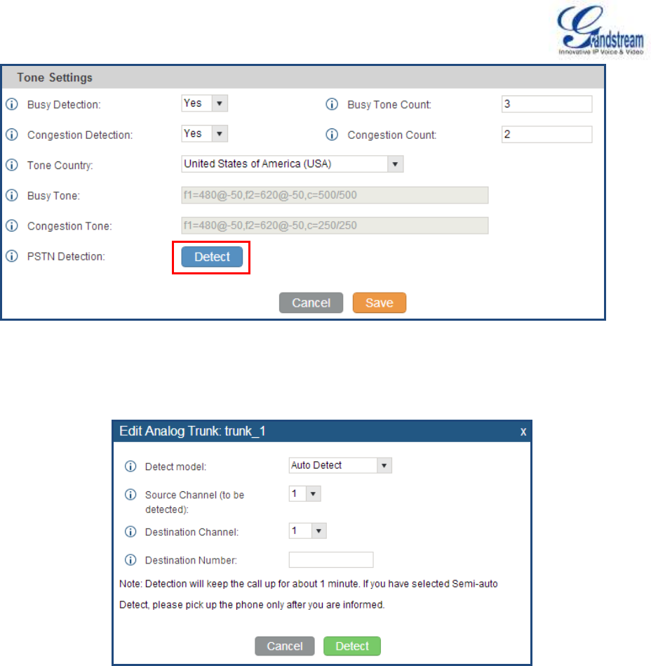
Firmware Version 1.0.0.5
UCM6510 IP PBX User Manual
Page 71 of 192
Figure 24: UCM6510 FXO Tone Settings
4. Click on "Detect" to start PSTN detection.
Figure 25: UCM6510 PSTN Detection
If there are two FXO ports connected to PSTN lines, use the following settings for auto-detection.
Detect Model: Auto Detect.
Source Channel: The source channel to be detected.
Destination Channel: The channel to help detecting. For example, the second FXO port.
Destination Number: The number to be dialed for detecting. This number must be the actual
PSTN number for the FXO port used as the destination channel.
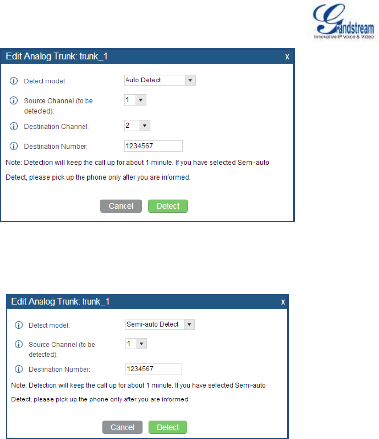
Firmware Version 1.0.0.5
UCM6510 IP PBX User Manual
Page 72 of 192
Figure 26: UCM6510 PSTN Detection: Auto Detect
If there is only one FXO port connected to PSTN line, use the following settings for auto-detection.
Figure 27: UCM6510 PSTN Detection: Semi-Auto Detect
Detect Model: Semi-auto Detect.
Source Channel: The source channel to be detected.
Destination Number: The number to be dialed for detecting. This number could be a cell phone
number or other PSTN number that can be reached from the source channel PSTN number.
5. Click "Detect" to start detecting. The source channel will initiate a call to the destination number. For
"Auto Detect", the call will be automatically answered. For "Semi-auto Detect", the UCM6510 web GUI
will display prompt to notify the user to answer or hang up the call to finish the detecting process.
6. Once done, the detected result will show. Users could save the detecting result as the current
UCM6510 settings.

Firmware Version 1.0.0.5
UCM6510 IP PBX User Manual
Page 73 of 192
Table 23: PSTN Detection For Analog Trunk
Detect Model
Select "Auto Detect" or "Semi-auto Detect" for PSTN detection.
Auto Detect
Please make sure two or more channels are connected to the
UCM6510 and in idle status before starting the detection. During the
detection, one channel will be used as caller (Source Channel) and
another channel will be used as callee (Destination Channel). The
UCM6510 will control the call to be established and hang up
between caller and callee to finish the detection.
Semi-auto Detect
Semi-auto detection requires answering or hanging up the call
manually. Please make sure one channel is connected to the
UCM6510 and in idle status before starting the detection. During the
detection, source channel will be used as caller and send the call to
the configured Destination Number. Users will then need follow the
prompts in web GUI to help finish the detection.
The default setting is "Auto Detect".
Source Channel
Select the channel to be detected.
Destination Channel
Select the channel to help detect when "Auto Detect" is used.
Destination Number
Configure the number to be called to help the detection.
Note:
The PSTN detection process will keep the call up for about 1 minute.
If "Semi-auto Detect' is used, please pick up the call only after informed from the web GUI prompt.
Once the detection is successful, the detected parameters "Busy Tone", "Polarity Reversal" and
"Current Disconnect by PSTN" will be filled into the corresponding fields in the analog trunk
configuration.
ANALOG HARDWARE CONFIGURATION
The analog hardware (FXS port and FXO port) on the UCM6510 can be configured under web
GUI->PBX->Ports Config->Analog Hardware. Click on to edit signaling preference for FXS port or
configure ACIM settings for FXO port.
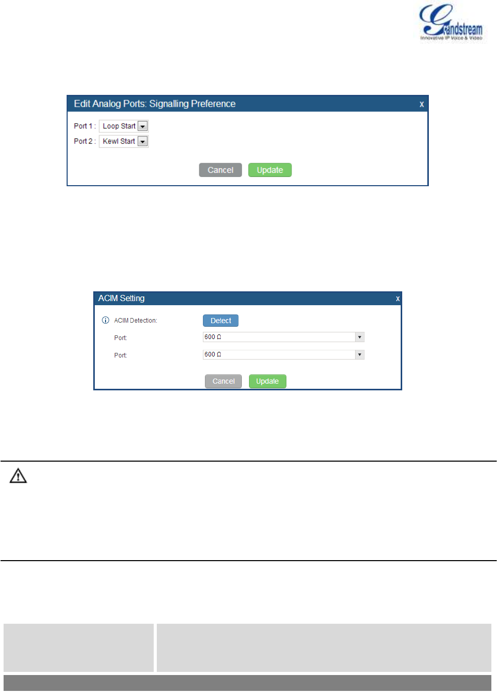
Firmware Version 1.0.0.5
UCM6510 IP PBX User Manual
Page 74 of 192
Select "Loop Start" or "Kewl Start" for each FXS port. And then click on "Update" to save the change.
Figure 28: FXS Ports Signaling Preference
For FXO port, users could manually enter the ACIM settings by selecting the value from dropdown list for
each port. Or users could click on "Detect" for the UCM6510 to automatically detect the ACIM value. The
detecting value will be automatically filled into the settings.
Figure 29: FXO Ports ACIM Settings
Note:
ACIM setting is very important for the FXO/PSTN line to work properly on the UCM6510. If the users
experience echo, caller ID or disconnecting issue, please make sure to run the ACIM detection to find out
the correct value for impedance setting.
Table 24: PBX/Ports Config/Analog Hardware
Tone Region
Select country to set the default tones for dial tone, busy tone, ring tone
and etc to be sent from the FXS port. The default setting is "United
States of America (USA)".
Advanced Settings

Firmware Version 1.0.0.5
UCM6510 IP PBX User Manual
Page 75 of 192
FXO Opermode
Select country to set the On Hook Speed, Ringer Impedance, Ringer
Threshold, Current Limiting, TIP/RING voltage adjustment, Minimum
Operational Loop Current, and AC Impedance as predefined for your
country's analog line characteristics. The default setting is "United
States of America (USA)".
FXS Opermode
Select country to set the On Hook Speed, Ringer Impedance, Ringer
Threshold, Current Limiting, TIP/RING voltage adjustment, Minimum
Operational Loop Current, and AC Impedance as predefined for your
country's analog line characteristics. The default setting is "United
States of America (USA)".
FXS TISS Override
Configure to enable or disable override Two-Wire Impedance Synthesis
(TISS). The default setting is No.
If enabled, users can select the impedance value for Two-Wire
Impedance Synthesis (TISS) override. The default setting is 600Ω.
PCMA Override
Select the codec to be used for analog lines. North American users
should choose PCMU. All other countries, unless already known, should
be assumed to be PCMA. The default setting is PCMU.
Note:
This option requires system reboot to take effect.
Boost Ringer
Configure whether normal ringing voltage (40V) or maximum ringing
voltage (89V) for analog phones attached to the FXS port is required.
The default setting is "Normal".
Fast Ringer
Configure to increase the ringing speed to 25HZ. This option can be
used with "Low Power" option. The default setting is "Normal".
Low Power
Configure the peak voltage up to 50V during "Fast Ringer" operation.
This option is used with "Fast Ringer". The default setting is "Normal".
Ring Detect
If set to "Full Wave", false ring detection will be prevented for lines where
Caller ID is sent before the first ring and proceeded by a polarity
reversal, as in UK. The default setting is "Standard".
FXS MWI Mode
Configure the type of Message Waiting Indicator on FXS lines. The
default setting is "FSK".
FSK: Frequency Shift Key Indicator
NEON: Light Neon Bulb Indicator.
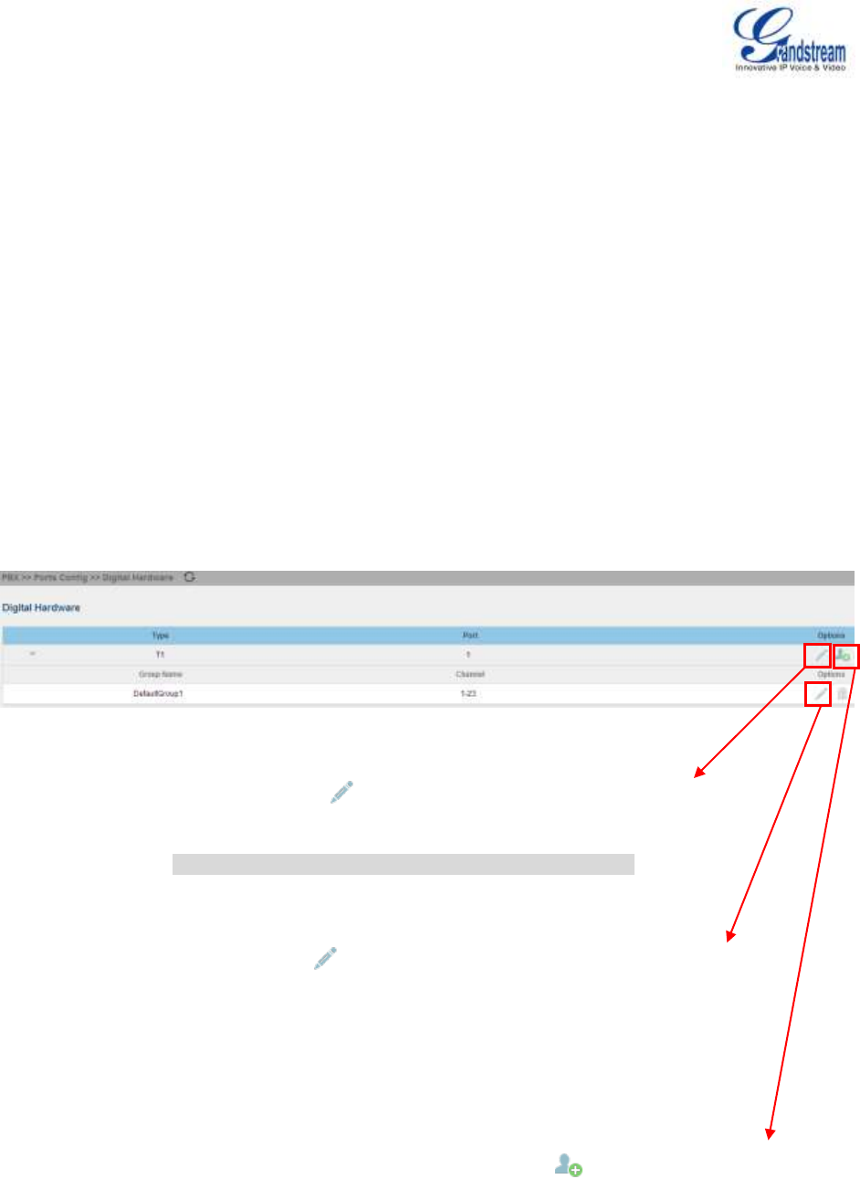
Firmware Version 1.0.0.5
UCM6510 IP PBX User Manual
Page 76 of 192
DIGITAL TRUNKS
The UCM6510 supports E1/T1 which are physical connection technology used in digital network. T1 is the
North American format whereas E1 is the European format with different transmission speed. Currently PRI
signaling is supported for the E1/T1 interface on the UCM6510.
To set up digital trunk on the UCM6510:
Go to web GUI->PBX->Ports Config->Digital Hardware to configure port type and channels.
Go to web GUI->PBX->Basic/Call Routes->Digital Trunks to add and edit digit trunks.
DIGITAL HARDWARE CONFIGURATION
Go to web GUI->PBX->Ports Config->Digital Hardware page and configure the following:
Figure 30: Digital Hardware Configuration
Step 1: Click on to edit digital ports. Please see configuration
parameters in
[Table 25: Ports Config/Digital Hardware: Edit Digital Ports].
Step 2: Click on to edit group. This assigns channels to be used for
the
digital port. For E1, 30 B channels can be assigned to the default group;
for T1, 23 B channels can be assigned to the default group.
Step 3: If fewer than 30 B channels for E1 or 23 B channels for T1
assigned in default group, users can click on to add more groups.
This is not necessary in most cases and only default group is needed.

Firmware Version 1.0.0.5
UCM6510 IP PBX User Manual
Page 77 of 192
The following dialog shows the digital port configuration parameters. Click on "Show Advanced Options" to
view more options.
Table 25: Ports Config/Digital Hardware: Edit Digital Ports
Span Type
Select the digital channel mode "E1", "T1" or "J1" (J1 is TBD).
Clock
All T1/E1 spans generate a clock signal on their transmit side. The
parameter determines whether the clock signal from the far end of the
T1/E1 is used as the master source of clock timing. If the far end is used
as the master, the PBX system clock will synchronize to it.
Master: The port will never be used as a source of timing. This is
appropriate when you know the far end should always be a slave to
you.
Slave: The equipment at the far end of the E1/T1 link is the preferred
source of the master clock.
Signaling
If the far end is set to "PRI_NET", this option should be set to
"PRI_CPE" on the UCM6510.
LBO
The line build-out (LBO) is the distance between the operators and the
PBX. Please use the default value 0dB unless the distance is long.
RX Gain
Configure the RX gain for the receiving channel of digital port. The valid
range is from -24dB to +12dB.
TX Gain
Configure the TX Gain for the transmitting channel of digital port. The
valid range is -24dB to +12dB.
Codec
Select alaw (PCMA) or ulaw (PCMU). The default code is alaw for E1
and ulaw for T1.
Advanced Options
Switch Type
Select switch type.
euroisdn: EuroISDN (common in Europe)
national: National ISDN type 2 (common in the US)
dms100: Nortel DMS100
4ess: AT&T 4ESS
5ess: Lucent 5ESS
ni1: old national ISDN type 1
qsig: Q.SIG
Coding
For T1, select "ami" or "b8zs"; for E1, select "ami" or "hdb3".
CRC
For E1, select whether to use CRC4 or CRC6. For J1 (pending), CRC6

Firmware Version 1.0.0.5
UCM6510 IP PBX User Manual
Page 78 of 192
is used by default.
PRI Dial Plan
This setting is used to specify the type of the callee number. The service
provider will usually verify this. The default setting is "unknown". In some
very unusual circumstances, you may need set to "dynamic" or
"redundant".
Note:
When one type is selected, you might not be able to dial another class of
numbers. For example, if "national" is configured, you won't be able to
dial local or international numbers.
PRI Local Dial Plan
This setting is used to specify the type of the caller number. The service
provider will usually verify this.
International Prefix
National Prefix
Local Prefix
Private Prefix
Unknown Prefix
Configure the prefix in PRI local dial plan for each type.
PRI Indication
Select the PRI Indication.
Outofband: Use RELEASE, DISCONNECT or other messages with
CAUSE to indicate call progress (e.g., cause: unassigned number or
user busy).
Inband: use in-band tones to play busy or congestion signal to the
other side. This is the default setting.
Reset Interval
The interval that restarts idle channels.
PRI Exclusive
This setting is used to set up the ChannelID in SETUP message. If
enabled, only the specified B channel can be used. Otherwise, select
one of the channels in B channel. If you need override the existing
channels selection routine and force all PRI channels to be marked as
exclusively selected, please enable it.
Facility Enable
If selected, transmission of facility-based ISDN supplementary services
(such as caller name from CPE over facility) will be enabled.
NSF
Some switches (AT&T especially) require network specific facility.
Currently the supported values are "none", "sdn", "megacom",
"tollfreemegacom", "accunet".

Firmware Version 1.0.0.5
UCM6510 IP PBX User Manual
Page 79 of 192
DIGITAL TRUNK CONFIGURATION
After configuring digital hardware, go to web GUI->PBX->Basic/Call Routes->Digital Trunks.
Click on "Create New Digital Trunk" to add a new digital trunk.
Click on to configure detailed parameters for the digital trunk.
Click on to configure Direct Outward Dialing (DOD) for the digital Trunk.
Click on to delete the digital trunk.
The digital trunk parameters are listed in the table below.
Table 26: Digital Trunk Configuration Parameters
Trunk Name
Configure trunk name to identify the digital trunk.
Channel Group
Configure the digital channel group used by the trunk.
Hide CallerID
Configure to hide outgoing caller ID. The default setting is "No".
Keep Trunk CID
If enabled, the trunk CID will not be overridden by extension's CID when
the extension has CID configured. The default setting is "No".
Caller ID
Configure the Caller ID. This is the number that the trunk will try to use
when making outbound calls. For some providers, it might not be
possible to set the CallerID with this option and this option will be
ignored.
When making outgoing calls, the following rules are used to determine
which CallerID will be used if they exist:
The CallerID configured for the extension will be looked up first.
If no CallerID configured for the extension, the CallerID configured
for the trunk will be used.
If the above two are missing, the "Global Outbound CID" defined in
web GUI->PBX->Internal Options->General will be used.
CallerID Name
Configure the new name of the caller when the extension has no
CallerID Name configured.
Auto Record
Enable automatic recording for the calls using this trunk (for SIP trunk
only). The default setting is disabled. The recording files are saved in
external storage device if plugged in and can be accessed under web
GUI->CDR->Recording Files.
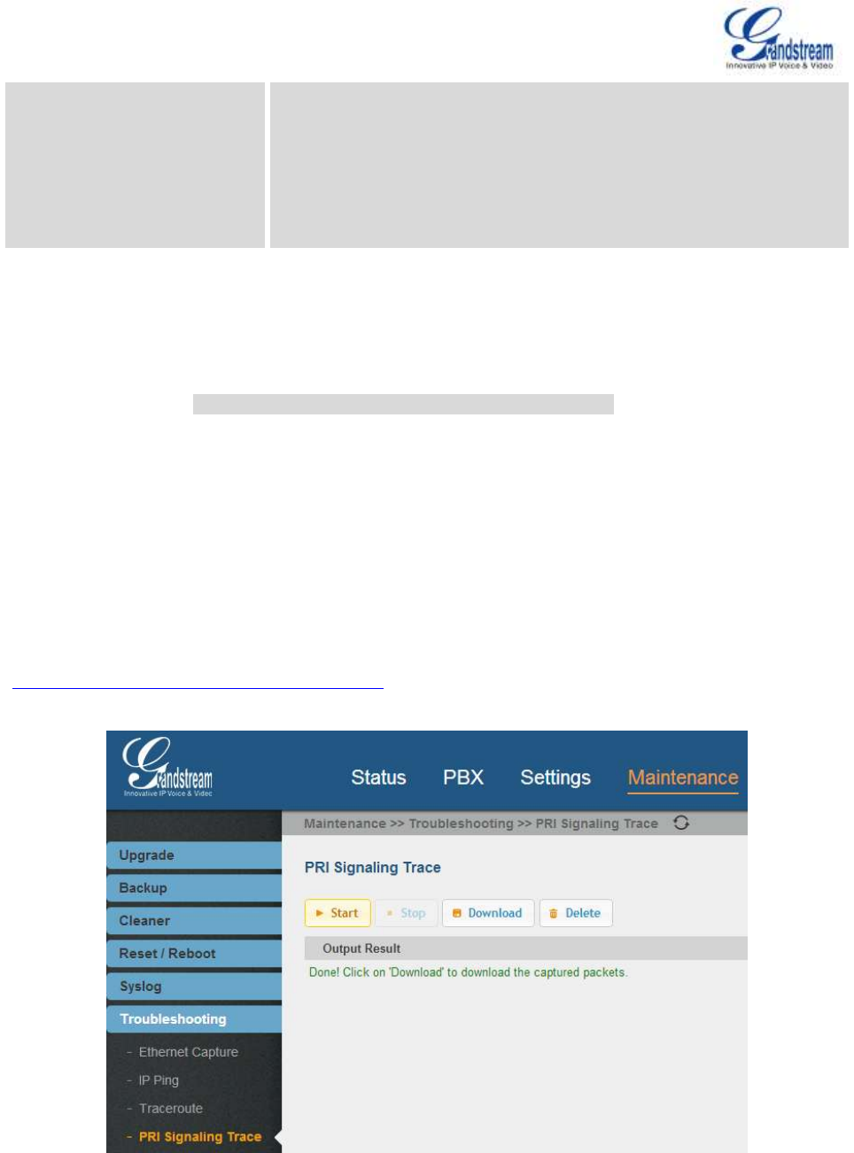
Firmware Version 1.0.0.5
UCM6510 IP PBX User Manual
Page 80 of 192
Fax Detection
Enable to detect Fax signal from the trunk during the call and send the
received Fax to the default Email address in Fax setting page under web
GUI->PBX->Internal Options->Fax/T.38.
Note:
If enabled, Fax Pass-through cannot be used.
DIRECT OUTWARD DIALING (DOD) VIA DIGITAL TRUNKS
Please refer to section [DIRECT OUTWARD DIALING (DOD) VIA VOIP TRUNKS].
DIGITAL TRUNK TROUBLESHOOTING
After configuring the digital trunk on the UCM6510 as described above, if it doesn't work as expected, go to
web GUI->Maintenance->Troubleshooting->PRI Signaling Trace to capture a trace for the T1/E1
interface. The users can take a look at the trace for basic analysis or contact Grandstream Technical
support in the following link for further assistance if the issue is not resolved.
http://www.grandstream.com/index.php/support
Figure 31: Troubleshooting Digital Trunks

Firmware Version 1.0.0.5
UCM6510 IP PBX User Manual
Page 81 of 192
Click on "Start" to start capturing trace. The output result shows "Capturing...".
Once the test is done, click on "Stop" to stop the trace.
Click on "Download" to download the trace.
To delete the trace, click on "Delete".

Firmware Version 1.0.0.5
UCM6510 IP PBX User Manual
Page 82 of 192
VOIP TRUNKS
VOIP TRUNK CONFIGURATION
VoIP trunks can be configured in UCM6510 under web GUI->PBX->Basic/Call Routes->VoIP Trunks.
Once created, the VoIP trunks will be listed with Provider Name, Type, Hostname/IP, Username and
Options to edit/detect the trunk.
Click on "Create New SIP Trunk" or "Create New IAX Trunk" to add a new VoIP trunk.
Click on to configure detailed parameters for the VoIP trunk.
Click on to configure Direct Outward Dialing (DOD) for the SIP Trunk.
Click on to start LDAP Sync.
Click on to delete the VoIP trunk.
The VoIP trunk options are listed in the table below.
Table 27: SIP Trunk Configuration Parameters
Create New SIP Trunk
Type
Select the VoIP trunk type.
Peer SIP Trunk
Register SIP Trunk
Provider Name
Configure a unique label to identify this trunk when listed in outbound
rules, inbound rules and etc.
Host Name
Configure the IP address or URL for the VoIP providers server of the
trunk.
Keep Trunk CID
If enabled, the trunk CID will not be overridden by extension's CID when
the extension has CID configured. The default setting is "No".
Username
Enter the username to register to the trunk from the provider when
"Register SIP Trunk" type is selected.
Password
Enter the password to register to the trunk from the provider when
"Register SIP Trunk" is selected.
Auth ID
Enter the Authentication ID for "Register Trunk" type.
Outbound Proxy
Enter the IP address or URL of the outbound proxy for "Register SIP

Firmware Version 1.0.0.5
UCM6510 IP PBX User Manual
Page 83 of 192
Trunk" type.
Auto Record
Enable automatic recording for the calls using this trunk (for SIP trunk
only). The default setting is disabled. The recording files are saved in
external storage if plugged in and can be accessed under web
GUI->CDR->Recording Files.
Peer SIP Trunk Configuration Parameters
Provider Name
Configure the provider name for the VoIP trunk. This is a unique label to
identify the trunk when listed in outbound rules, inbound rules and etc.
Host Name
Configure the IP address or URL for the VoIP provider server of the
trunk.
Transport
Configure the SIP transport protocol to be used in this trunk. The default
setting is "All - UDP Primary".
UDP Only
TCP Only
TLS Only
All - UDP Primary: UDP is the primary transport protocol when all
the other SIP transport methods are available too.
All - TCP Primary: TCP is the primary transport protocol when all the
other SIP transport methods are available too.
All - TLS Primary: TLS is the primary transport protocol when all the
other SIP transport methods are available too.
Keep Trunk CID
If enabled, the trunk CID will not be overridden by extension's CID when
the extension has CID configured. The default setting is "No".
Caller ID
Configure the Caller ID. This is the number that the trunk will try to use
when making outbound calls. For some providers, it might not be
possible to set the CallerID with this option and this option will be
ignored.
When making outgoing calls, the following rules are used to determine
which CallerID will be used if they exist:
The CallerID configured for the extension will be looked up first.
If no CallerID configured for the extension, the CallerID configured
for the trunk will be used.
If the above two are missing, the "Global Outbound CID" defined in
web GUI->PBX->Internal Options->General will be used.
CallerID Name
Configure the name of the caller to be displayed when the extension has
no CallerID Name configured.

Firmware Version 1.0.0.5
UCM6510 IP PBX User Manual
Page 84 of 192
Codec Preference
Select audio and video codec for the VoIP trunk. The available codecs
are: PCMU, PCMA, GSM, AAL2-G.726-32, G.726, G.722, G.729,
G.723, ILBC, ADPCM, H.264, H.263, H.263p.
Auto Record
Enable automatic recording for the calls using this trunk. The default
setting is disabled. The recording files are saved in external storage if
plugged in and can be accessed under web GUI->CDR->Recording
Files.
DID Mode
Configure where to get the destination ID of an incoming SIP call, from
SIP Request-line or To-header. The default is set to "Request-line".
Enable Qualify
If enabled, the UCM6510 will regularly send SIP OPTIONS to the device
to check if the device is still online. The default setting is "No".
Qualify Timeout
When "Enable Qualify" option is set to "Yes", configure the timeout (in
ms) for the Qualify SIP message. If no response is received within the
timeout, the device is considered offline. The default setting is 1000ms.
Qualify Frequency
When "Enable Qualify" option is set to "Yes", configure the interval (in
seconds) of the SIP OPTIONS message sent to the device to check if
the device is still online. The default setting is 60 seconds.
Fax Detection
Enable to detect Fax signal from the trunk during the call and send the
received Fax to the default Email address in Fax setting page under web
GUI->PBX->Internal Options->Fax/T.38.
Note:
If enabled, Fax Pass-through cannot be used.
SRTP
Enable SRTP for the VoIP trunk. The default setting is "No".
Sync LDAP Enable
If enabled, the local UCM6510 will automatically provide and update the
local LDAP contacts to the remote UCM6510 SIP peer trunk. In order to
ensure successful synchronization, the remote UCM6510 peer also
needs to enable this option on the SIP peer trunk. The default setting is
"No".
Sync LDAP Password
This is the password used for LDAP contact file encryption and
decryption during the LDAP sync process. The password must be the
same on both UCM6510 peers o ensure successful synchronization.
Sync LDAP Port
Configure the TCP port used LDAP sync feature between two peer
UCM6510.
LDAP Outbound Rule
Specify an outbound rule for LDAP sync feature. The UCM6510 will
automatically modify the remote contacts by adding prefix parsed from
this rule.
LDAP Dialed Prefix
Specify the prefix for LDAP sync feature. The UCM6510 will

Firmware Version 1.0.0.5
UCM6510 IP PBX User Manual
Page 85 of 192
automatically modify the remote contacts by adding this prefix.
Register SIP Trunk Configuration Parameters
Provider Name
Configure the provider name for the VoIP trunk. This is a unique label to
identify the trunk when listed in outbound rules, inbound rules and etc.
Host Name
Configure the IP address or URL for the VoIP provider server of the
trunk.
Transport
Configure the SIP transport protocol to be used in this trunk. The default
setting is "All - UDP Primary".
UDP Only
TCP Only
TLS Only
All - UDP Primary: UDP is the primary transport protocol when all
the other SIP transport methods are available too.
All - TCP Primary: TCP is the primary transport protocol when all the
other SIP transport methods are available too.
All - TLS Primary: TLS is the primary transport protocol when all the
other SIP transport methods are available too.
Keep Trunk CID
When enabled, it can avoid overridden by extension's CID if the
extension has CID configured. The default setting is enabled.
Username
Enter the username to register to the trunk from the provider.
Password
Enter the password to register to the trunk from the provider.
Auth ID
This is the authentication ID for the UCM6510 to register to the trunk if
required by the provider. If not specified, the CallerID name will be sued
for authentication.
Codec Preference
Select audio and video codec for the VoIP trunk. The available codecs
are: PCMU, PCMA, GSM, AAL2-G.726-32, G.726, G.722, G.729,
G.723, ILBC, ADPCM, H.264, H.263, H.263p.
From Domain
Configure the actual domain name where the extension comes from.
This can be used to override the From Header.
For example, "trunk.UCM6510.provider.com" is the From Domain in
From Header: sip:1234567@trunk.UCM6510.provider.com.
From User
Configure the actual user name of the extension. This can be used to
override the From Header. There are cases where there is a single ID
for registration (single trunk) with multiple DIDs.
For example, "1234567" is the From User in From Header:
sip:1234567@trunk.UCM6510.provider.com.

Firmware Version 1.0.0.5
UCM6510 IP PBX User Manual
Page 86 of 192
Outbound Proxy Support
Select to enable outbound proxy in this trunk. The default setting is "No".
Outbound Proxy
When outbound proxy support is enabled, enter the IP address or URL
of the outbound proxy.
Auto Record
Enable automatic recording for the calls using this trunk. The default
setting is disabled. The recording files can be accessed under web
GUI->CDR->Recording Files.
DID Mode
Configure where to get the destination ID of an incoming SIP call, from
SIP Request-line or To-header. The default is set to "Request-line".
Enable Qualify
If enabled, the UCM6510 will regularly send SIP OPTIONS to the device
to check if the device is still online. The default setting is "No".
Qualify Timeout
When "Enable Qualify" option is set to "Yes", configure the timeout (in
ms) for the Qualify SIP message. If no response is received within the
timeout, the device is considered offline. The default setting is 1000ms.
Qualify Frequency
When "Enable Qualify" option is set to "Yes", configure the interval (in
seconds) of the SIP OPTIONS message sent to the device to check if
the device is still online. The default setting is 60 seconds.
Fax Detection
Enable to detect Fax signal from the trunk during the call and send the
received Fax to the default Email address in Fax setting page under web
GUI->PBX->Internal Options->Fax/T.38.
Note:
If enabled, Fax Pass-through cannot be used.
SRTP
Enable SRTP for the VoIP trunk. The default setting is "No".
Table 28: IAX Trunk Configuration Parameters
Create New IAX Trunk
Type
Select the VoIP trunk type.
Peer IAX Trunk
Register IAX Trunk
Provider Name
Configure a unique label to identify this trunk when listed in outbound
rules, inbound rules and etc.
Host Name
Configure the IP address or URL for the VoIP providers server of the
trunk.
Keep Trunk CID
If enabled, the trunk CID will not be overridden by extension's CID when
the extension has CID configured. The default setting is "No".
Username
Enter the username to register to the trunk from the provider when

Firmware Version 1.0.0.5
UCM6510 IP PBX User Manual
Page 87 of 192
"Register IAX Trunk" type is selected.
Password
Enter the password to register to the trunk from the provider when
"Register IAX Trunk" type is selected.
Peer IAX Trunk Configuration Parameters
Provider Name
Configure the provider name for the VoIP trunk. This is a unique label to
identify the trunk when listed in outbound rules, inbound rules and etc.
Host Name
Configure the IP address or URL for the VoIP provider server of the
trunk.
Keep Trunk CID
If enabled, the trunk CID will not be overridden by extension's CID when
the extension has CID configured. The default setting is "No".
Caller ID
Configure the Caller ID. This is the number that the trunk will try to use
when making outbound calls. For some providers, it might not be
possible to set the CallerID with this option and this option will be
ignored.
When making outgoing calls, the following rules are used to determine
which CallerID will be used if they exist:
The CallerID configured for the extension will be looked up first.
If no CallerID configured for the extension, the CallerID configured
for the trunk will be used.
If the above two are missing, the "Global Outbound CID" defined in
web GUI->PBX->Internal Options->General will be used.
CallerID Name
Configure the name of the caller to be displayed when the extension has
no CallerID Name configured.
Codec Preference
Select audio and video codec for the VoIP trunk. The available codecs
are: PCMU, PCMA, GSM, AAL2-G.726-32, G.726, G.722, G.729,
G.723, ILBC, ADPCM, H.264, H.263, H.263p.
Enable Qualify
If enabled, the UCM6510 will regularly send SIP OPTIONS to the device
to check if the device is still online. The default setting is "No".
Qualify Timeout
When "Enable Qualify" option is set to "Yes", configure the timeout (in
ms) for the Qualify SIP message. If no response is received within the
timeout, the device is considered offline. The default setting is 1000ms.
Qualify Frequency
When "Enable Qualify" option is set to "Yes", configure the interval (in
seconds) of the SIP OPTIONS message sent to the device to check if
the device is still online. The default setting is 60 seconds.
Fax Detection
Enable to detect Fax signal from the trunk during the call and send the
received Fax to the default Email address in Fax setting page under web

Firmware Version 1.0.0.5
UCM6510 IP PBX User Manual
Page 88 of 192
GUI->PBX->Internal Options->Fax/T.38.
Note:
If enabled, Fax Pass-through cannot be used.
Register IAX Trunk Configuration Parameters
Provider Name
Configure the provider name for the VoIP trunk. This is a unique label to
identify the trunk when listed in outbound rules, inbound rules and etc.
Host Name
Configure the IP address or URL for the VoIP provider server of the
trunk.
Keep Trunk CID
When enabled, it can avoid overridden by extension's CID if the
extension has CID configured. The default setting is enabled.
Caller ID
Configure the Caller ID. This is the number that the trunk will try to use
when making outbound calls. For some providers, it might not be
possible to set the CallerID with this option and this option will be
ignored.
When making outgoing calls, the following rules are used to determine
which CallerID will be used if they exist:
The CallerID configured for the extension will be looked up first.
If no CallerID configured for the extension, the CallerID configured
for the trunk will be used.
If the above two are missing, the "Global Outbound CID" defined in
web GUI->PBX->Internal Options->General will be used.
CallerID Name
Configure the name of the caller to be displayed when the extension has
no CallerID Name configured.
Username
Enter the username to register to the trunk from the provider.
Password
Enter the password to register to the trunk from the provider.
Auth ID
This is the authentication ID for the UCM6510 to register to the trunk if
required by the provider. If not specified, the CallerID name will be sued
for authentication.
Codec Preference
Select audio and video codec for the VoIP trunk. The available codecs
are: PCMU, PCMA, GSM, AAL2-G.726-32, G.726, G.722, G.729,
G.723, ILBC, ADPCM, H.264, H.263, H.263p.
Enable Qualify
If enabled, the UCM6510 will regularly send SIP OPTIONS to the device
to check if the device is still online. The default setting is "No".
Qualify Timeout
When "Enable Qualify" option is set to "Yes", configure the timeout (in
ms) for the Qualify SIP message. If no response is received within the

Firmware Version 1.0.0.5
UCM6510 IP PBX User Manual
Page 89 of 192
timeout, the device is considered offline. The default setting is 1000ms.
Qualify Frequency
When "Enable Qualify" option is set to "Yes", configure the interval (in
seconds) of the SIP OPTIONS message sent to the device to check if
the device is still online. The default setting is 60 seconds.
Fax Detection
Enable to detect Fax signal from the trunk during the call and send the
received Fax to the default Email address in Fax setting page under web
GUI->PBX->Internal Options->Fax/T.38.
Note:
If enabled, Fax Pass-through cannot be used.
DIRECT OUTWARD DIALING (DOD) VIA VOIP TRUNKS
The UCM6510 provides Direct Outward Dialing (DOD) which is a service of a local phone company (or
local exchange carrier) that allows subscribers within a company's PBX system to connect to outside lines
directly.
Example of how DOD is used:
Company ABC has a SIP trunk. This SIP trunk has 4 DIDs associated to it. The main number of the office
is routed to an auto attendant. The other three numbers are direct lines to specific users of the company.
At the moment when a user makes an outbound call their caller ID shows up as the main office number.
This poses a problem as the CEO would like their calls to come from their direct line. This can be
accomplished by configuring DOD for the CEO’s extension.
Steps on how to configure DOD on the UCM:
1. To setup DOD go to UCM6510 web GUI->PBX->Basic/Call Routes->VoIP Trunks page.
2. Click to access the DOD options for the selected SIP Trunk.
3. Click "Create a new DOD" to begin your DOD setup
4. For "DOD Number" enter one of the numbers(DIDs) from your SIP trunk provider. In the example above
Company ABC received 4 DIDs from their provider. ABC will enter in the number for the CEO's direct
line.
5. Select an extension from the "Available Extensions" list. Users have the option of selecting more than
one extension. In this case, Company ABC would select the CEO's extension. After making the
selection, click on the button to move the extension(s) to the "Selected Extensions" list.
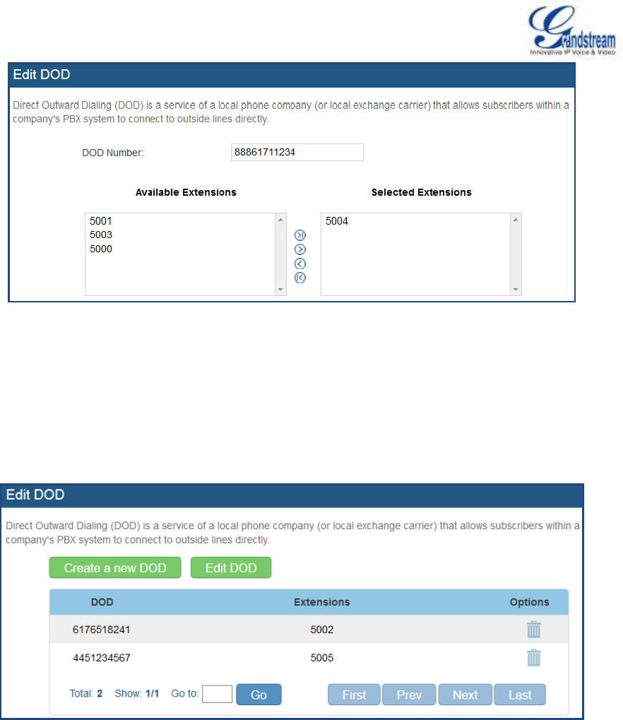
Firmware Version 1.0.0.5
UCM6510 IP PBX User Manual
Page 90 of 192
Figure 32: DOD extension selection
6. Click "Save" at the bottom.
Once completed, the user will return to the Edit DOD page that shows all the extensions that are associated
to a particular DOD.
Figure 33: Edit DOD

Firmware Version 1.0.0.5
UCM6510 IP PBX User Manual
Page 91 of 192
CALL ROUTES
OUTBOUND ROUTES
In the UCM6510, an outgoing calling rule pairs an extension pattern with a trunk used to dial the pattern.
This allows different patterns to be dialed through different trunks (e.g., "Local" 7-digit dials through a FXO
while "Long distance" 10-digit dials through a low-cost SIP trunk). Users can also set up a failover trunk to
be used when the primary trunk fails.
Go to web GUI->PBX->Basic/Call Routes->Outbound Routes to add and edit outbound rules.
Click on "Create New Outbound Rule" to add a new outbound route.
Click on to edit the outbound route.
Click on to delete the outbound route.
Click on to move the outbound route up/down to arrange the priority of the outbound rule.
The outbound rule listed on the top has higher priority. When the dialing pattern matches two or more
outbound rules (for example, the same pattern is configured for 2 different trunks; or dialing out 1000
matches pattern 1xxx for trunk 1 and pattern 100x for trunk 2), the one listed on the top will be used.
Table 29: Outbound Route Configuration Parameters
Calling Rule Name
Configure the name of the calling rule (e.g., local, long_distance, and
etc). Letters, digits, _ and - are allowed.
Pattern
All patterns are prefixed with the "_".
Special characters:
X: Any Digit from 0-9.
Z: Any Digit from 1-9.
N: Any Digit from 2-9.
".": Wildcard. Match one or more characters.
"!": Wildcard. Match zero or more characters immediately.
Example: [12345-9] - Any digit from 1 to 9.
Password
Configure the password for users to use this rule when making outbound
calls.
Privilege Level
Select privilege level for the outbound rule.
Internal: The lowest level required. All users can use this rule.
Local: Users with Local, National, or International level are allowed

Firmware Version 1.0.0.5
UCM6510 IP PBX User Manual
Page 92 of 192
to use this rule.
National: Users with National or International level are allowed to
use this rule.
International: The highest level required. Only users with
international level can use this rule.
The default setting is "International". Please be aware of the potential
security risks when using "Internal" level, which means all users can use
this outbound rule to dial out from the trunk.
Enable Filter on Source Caller
ID
When enabled, users could specify extensions allowed to use this
outbound route. "Privilege Level" is automatically disabled if using
"Enable Filter on Source Caller ID".
The following two methods can be used at the same time to define the
extensions as the source caller ID.
1. Select available extensions from the left to the right. This allows
users to specify arbitrary single extensions.
2. Custom Dynamic Route: define the pattern for the source caller ID.
This allows users to define extension range instead of selecting
them one by one.
All patterns are prefixed with the "_".
Special characters:
X: Any Digit from 0-9.
Z: Any Digit from 1-9.
N: Any Digit from 2-9.
".": Wildcard. Match one or more characters.
"!": Wildcard. Match zero or more characters immediately.
Example: [12345-9] - Any digit from 1 to 9.
Send This Call Through Trunk
Use Trunk
Select the trunk for this outbound rule.
Strip
Allows the user to specify the number of digits that will be stripped from
the beginning of the dialed string before the call is placed via the
selected trunk.
Example:
The users will dial 9 as the first digit of a long distance calls. However, 9
should not be sent out via analog lines and the PSTN line. In this case, 1
digit should be stripped before the call is placed.

Firmware Version 1.0.0.5
UCM6510 IP PBX User Manual
Page 93 of 192
Prepend
Specify the digits to be prepended before the call is placed via the trunk.
Those digits will be prepended after the dialing number is stripped.
Use Failover Trunk
Failover Trunk
Failover trunks can be used to make sure that a call goes through an
alternate route, when the primary trunk is busy or down. If "Use Failover
Trunk" is enabled and "Failover trunk" is defined, the calls that cannot be
placed via the regular trunk may have a secondary trunk to go through.
Example:
The user's primary trunk is a VoIP trunk and the user would like to use
the PSTN when the VoIP trunk is not available. The PSTN trunk can be
configured as the failover trunk of the VoIP trunk.
Strip
Allows the user to specify the number of digits that will be stripped from
the beginning of the dialed string before the call is placed via the
selected trunk.
Example:
The users will dial 9 as the first digit of a long distance calls. However, 9
should not be sent out via analog lines and the PSTN line. In this case, 1
digit should be stripped before the call is placed.
Prepend
Specify the digits to be prepended before the call is placed via the trunk.
Those digits will be prepended after the dialing number is stripped.
INBOUND ROUTES
Inbound routes can be configured via web GUI->PBX->Basic/Call Routes->Inbound Routes.
Click on "Create New Inbound Rule" button to add a new inbound route.
Click on "Blacklist" button to configure blacklist for all inbound routes.
Click on to edit the inbound route.
Click on to delete the inbound route.

Firmware Version 1.0.0.5
UCM6510 IP PBX User Manual
Page 94 of 192
INBOUND RULE CONFIGURATIONS
Table 30: Inbound Rule Configuration Parameters
Trunks
Select the trunk to configure the inbound rule.
DID Pattern
All patterns are prefixed with the "_".
Special characters:
X: Any Digit from 0-9.
Z: Any Digit from 1-9.
N: Any Digit from 2-9.
".": Wildcard. Match one or more characters.
"!": Wildcard. Match zero or more characters immediately.
Example: [12345-9] - Any digit from 1 to 9.
The pattern can be composed of two parts, divided by a ‘/’ character.
The first part is used to specify the dialed number the second part is
used to specify the caller ID and it is optional, if set it means only the
extension with the specific caller ID is allowed to call in or call out.
For example, patter '_2XXX/1234' means the only extension with the
caller ID '1234' is allowed to use this rule.
Privilege Level
Select privilege level for the inbound rule when a VoIP trunk is selected
in "Trunks" field.
Internal: The lowest level required. All users can use this rule.
Local: Users with Local, National or International level are allowed to
use this rule.
National: Users with National or International level are allowed to
use this rule.
International: The highest level required. Only users with
international level can use this rule.
This setting is used to compared with the outbound trunk's permission
level when the inbound call dials out via a trunk on the UCM6510.
Therefore, it's usually used only when the "Default Destination" is set to
"By DID".
Default Destination
Select the default destination for the inbound call.
Extension
Voicemail
Conference Room
Call Queue
Ring Group
Paging/Intercom
Voicemail Group

Firmware Version 1.0.0.5
UCM6510 IP PBX User Manual
Page 95 of 192
Fax
DISA
IVR
By DID
When "By DID" is used, the UCM6510 will look for the destination
based on the number dialed, which could be local extensions,
conference, call queue, ring group, paging/intercom group, IVR,
voicemail groups and Fax extension as configured in "DID
destination". If the dialed number matches the DID pattern, the call
will be allowed to go through.
Dial By Name
Strip
Specify the number of digits to strip from the beginning of the DID. This
is used when "By DID" is selected in "Default Destination".
Dial Trunk
Configure to allow the inbound call to dial out from the PBX's trunk or
not. The default setting is disabled. Please be aware of potential security
risk if "Dial Trunk" is enabled. The inbound call might be able to dial out
international calls from the PBX's trunk if allowed by the privilege level.
DID Destination
Select the DID destination if "By DID" is selected in "Default
Destination". Only the selected category can be reached by DID using
this inbound route.
Extension
Conference
Call Queue
Ring Group
Paging/Intercom Group
IVR
Voicemail Groups
Fax Extension
Dial By Name
Time Condition
Start Time
Select the start time "hour:minute" for the trunk to use the inbound rule.
End Time
Select the end time "hour:minute" for the trunk to use the inbound rule.
Date
Select "By Week" or "By Day" and specify the date for the trunk to use
the inbound rule.
Week
Select the day in the week to use the inbound rule.
Destination
Select the destination for the inbound call under the defined time
condition.
Extension
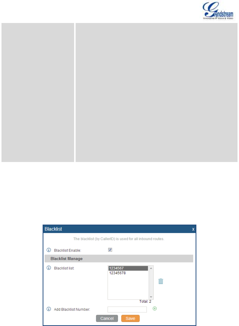
Firmware Version 1.0.0.5
UCM6510 IP PBX User Manual
Page 96 of 192
Voicemail
Conference Room
Call Queue
Ring Group
Paging/Intercom
Voicemail Group
Fax
DISA
IVR
By DID
When "By DID" is used, the UCM6510 will look for the destination
based on the number dialed, which could be local extensions,
conference, call queue, ring group, paging/intercom group, IVR,
voicemail groups and Fax extension as configured in "DID
destination". If the dialed number matches the DID pattern, the call
will be allowed to go through.
Configure the number of digits to be stripped in "Strip" option.
Dial By Name
BLACKLIST CONFIGURATIONS
In the UCM6510, Blacklist is supported for all inbound routes. Users could enable the Blacklist feature,
manage the Blacklist by clicking on "Blacklist".
Figure 34: Blacklist Configuration Parameters

Firmware Version 1.0.0.5
UCM6510 IP PBX User Manual
Page 97 of 192
Select the checkbox for "Blacklist Enable" to turn on Blacklist feature for all inbound routes. Blacklist is
disabled by default.
Enter a number in "Add Blacklist Number" field and then click to add to the list.
To remove a number from the Blacklist, select the number in "Blacklist list" and click on .
Note:
Users could also add a number to the Blacklist or remove a number from the Blacklist by dialing the feature
code for "Blacklist Add' (default: *40) and "Blacklist Remove" (default: *41) from an extension. The feature
code can be configured under web GUI->PBX->Internal Options->Feature Codes.

Firmware Version 1.0.0.5
UCM6510 IP PBX User Manual
Page 98 of 192
CONFERENCE BRIDGE
The UCM6510 supports conference bridge allowing 32 participants with up to 5 bridges at the same time.
The conference bridge configurations can be accessed under web GUI->PBX->Call
Features->Conference. In this page, users could create, edit, view, invite, manage the participants and
delete conference bridges. The conference bridge status and conference call recordings (if recording is
enabled) will be displayed in this web page as well.
CONFERENCE BRIDGE CONFIGURATIONS
Click on "Create New Conference Room" to add a new conference bridge.
Click on to edit the conference bridge.
Click on to delete the conference bridge.
Table 31: Conference Bridge Configuration Parameters
Extension
Configure the conference number for the users to dial into the
conference.
Password
When configured, the users who would like to join the conference call
must enter this password before accessing the conference bridge.
Note:
If "Public Mode" is enabled, the password is not required to join the
conference bridge thus this field is invalid.
The password has to be at least 4 characters.
Admin Password
Configure the password to join the conference bridge as administrator.
Conference administrator can manage the conference call via IVR (if
"Enable Caller Menu" is enabled) as well as invite other parties to join
the conference by dialing "0" (permission required from the invited party)
or "1" (permission not required from the invited party) during the
conference call.
Note:
If "Public Mode" is enabled, the password is not required to join the
conference bridge thus this field is invalid.
The password has to be at least 4 characters.

Firmware Version 1.0.0.5
UCM6510 IP PBX User Manual
Page 99 of 192
Enable Caller Menu
If enabled, conference participant could press the * key to access the
conference bridge menu. The default setting is "No".
Record Conference
If enabled, the calls in this conference bridge will be recorded
automatically in a .wav format file. All the recording files will be displayed
and can be downloaded in the conference web page. The default setting
is "No".
Quiet Mode
If enabled, if there are users joining or leaving the conference, voice
prompt or notification tone won't be played. The default setting is "No".
Note:
"Quiet Mode" and "Announce Callers" cannot be enabled at the same
time.
Wait For Admin
If enabled, the participants will not hear each other until the conference
administrator joins the conference. The default setting is "No".
Note:
If "Quiet Mode" is enabled, the voice prompt for "Wait For Admin" will not
be announced.
Enable User Invite
If enabled, users could press 0 to invite other users (with the users'
permission) or press 1 to invite other users (without the user's
permission) to join the conference. The default setting is "No".
Note:
Conference administrator can always invite other users without enabling
this option.
Announce Callers
If enabled, the caller will be announced to all conference participants
when there the caller joins the conference. The default setting is "No".
Note:
"Quiet Mode" and "Announce Callers" cannot be enabled at the same
time.
Public Mode
If enabled, no authentication will be required when joining the
conference call. The default setting is "Yes".
Play Hold Music For First
Caller
If enabled, the UCM6510 will play Hold music to the first participant in
the conference until another user joins in. The default setting is "No".
Music On Hold
Select the music on hold class to be played in conference call. This
option shows up if "Play Hold Music For First Caller" is enabled. Music
On Hold class can be set up under web UI->PBX->Internal
Options->Music On Hold.
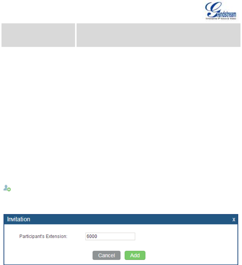
Firmware Version 1.0.0.5
UCM6510 IP PBX User Manual
Page 100 of 192
Skip Authentication When
Inviting User via Trunk from
web GUI
If enabled, the invitation from web GUI for a conference bridge with
password will skip the authentication for the invited users. The default
setting is "No".
JOIN A CONFERENCE CALL
Users could dial the conference bridge extension to join the conference. If password is required, enter the
password to join the conference as a normal user, or enter the admin password to join the conference as
administrator.
INVITE OTHER PARTIES TO JOIN CONFERENCE
When using the UCM6510 conference bridge, there are two ways to invite other parties to join the
conference.
Invite from web GUI.
For each conference bridge in UCM6510 web GUI->PBX->Call Features->Conference, there is an icon
for option "Invite a participant". Click on it and enter the number of the party you would like to invite.
Then click on "Add". A call will be sent to this number to join it into the conference.
Figure 35: Conference Invitation From web GUI
Invite by dialing 0 or 1 during conference call.
A conference participant can invite other parties to the conference by dialing from the phone during the
conference call. Please make sure option "Enable User Invite" is turned on for the conference bridge first.
Enter 0 or 1 during the conference call. Follow the voice prompt to input the number of the party you would
like to invite. A call will be sent to this number to join it into the conference.
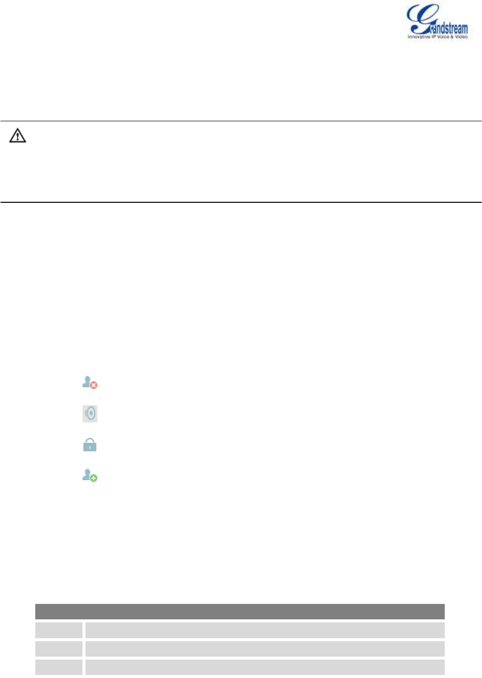
Firmware Version 1.0.0.5
UCM6510 IP PBX User Manual
Page 101 of 192
0: If 0 is entered to invite other party, once the invited party picks up the invitation call, a permission will be
asked to "accept" or "reject" the invitation before joining the conference.
1: If 1 is entered to invite other party, no permission will be required from the invited party.
Note:
Conference administrator can always invite other parties from the phone during the call by entering 0 or 1.
To join a conference bridge as administrator, enter the admin password when joining the conference. A
conference bridge can have multiple administrators.
DURING THE CONFERENCE
During the conference call, users can manage the conference from web GUI or IVR.
Manage the conference call from web GUI.
Log in UCM6510 web GUI during the conference call, the participants in each conference bridge will be
listed.
1. Click on to kick a participant from the conference.
2. Click on to mute the participant.
3. Click on to lock this conference bridge so that other users cannot join it anymore.
4. Click on to invite other users into the conference bridge.
Manage the conference call from IVR.
If "Enable Caller Menu" is enabled, conference participant can input * to enter the IVR menu for the
conference. Please see options listed in the table below.
Table 32: Conference Caller IVR Menu
Conference Administrator IVR Menu
1
Mute/unmute yourself.
2
Lock/unlock the conference bridge.
3
Kick the last joined user from the conference.
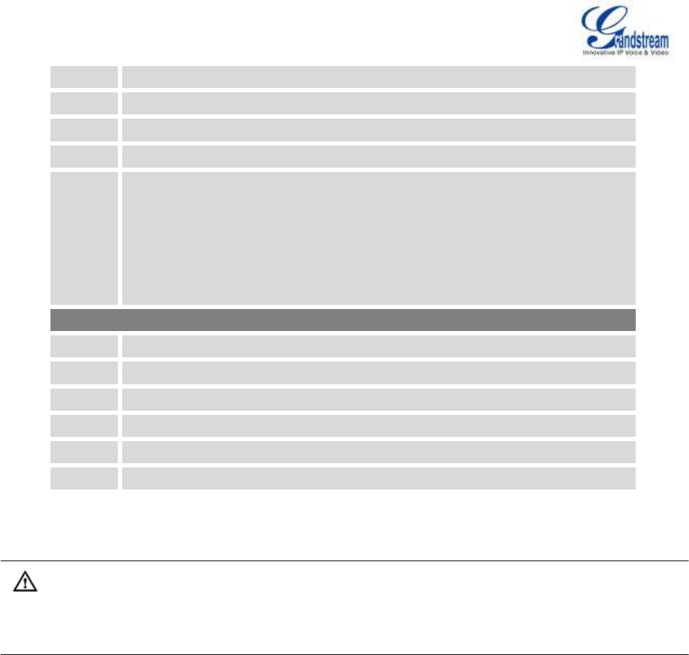
Firmware Version 1.0.0.5
UCM6510 IP PBX User Manual
Page 102 of 192
4
Decrease the volume of the conference call.
5
Decrease your volume .
6
Increase the volume of the conference call.
7
Increase your volume.
8
More options.
1: List all users currently in the conference call.
2: Kick all non-Administrator participants from the conference call.
3: Mute/Unmute all non-Administrator participants from the conference call.
4: Record the conference call.
8: Exit the caller menu and return to the conference.
Conference User IVR Menu
1
Mute/unmute yourself.
4
Decrease the volume of the conference call.
5
Decrease your volume.
6
Increase the volume of the conference call.
7
Increase your volume.
8
Exit the caller menu and return to the conference.
Note:
When there is participant in the conference, the conference bridge configuration cannot be modified.
RECORD CONFERENCE
The UCM6510 allows users to record the conference call and retrieve the recording from web
GUI->PBX->Call Features->Conference.
To record the conference call, when the conference bridge is in idle, enable "Record Conference" from the
conference bridge configuration dialog. Save the setting and apply the change. When the conference call
starts, the call will be automatically recorded in .wav format.
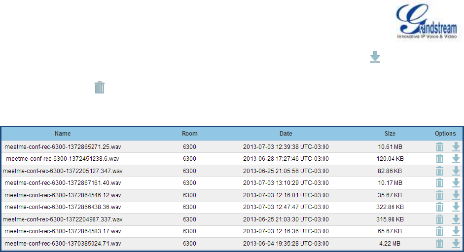
Firmware Version 1.0.0.5
UCM6510 IP PBX User Manual
Page 103 of 192
The recording files will be listed as below once available. Users could click on to download the
recording or click on to delete the recording.
Figure 36: Conference Recording

Firmware Version 1.0.0.5
UCM6510 IP PBX User Manual
Page 104 of 192
IVR
CONFIGURE IVR
IVR configurations can be accessed under the UCM6510 web GUI->PBX->Call Features->IVR. Users
could create, edit, view and delete an IVR.
Click on "Create New IVR" to add a new IVR.
Click on to edit the IVR configuration.
Click on to delete the IVR.
Table 33: IVR Configuration Parameters
Name
Configure the name of the IVR. Letters, digits, _ and - are allowed.
Extension
Enter the extension number for users to access the IVR.
Dial Other Extensions
If enabled, all callers to the IVR can dial other extensions. The default
setting is "No".
Dial Trunk
If enabled, all callers to the IVR is allowed to use trunk. The permission
must be configured for the users to use the trunk first. The default setting
is "No".
Permission
Assign permission level for outbound calls if "Dial Trunk" is enabled. The
available permissions are "Internal", "Local", "National" and
"International" from the lowest level to the highest level. The default
setting is "Internal". If the user tries to dial outbound calls after dialing
into the IVR, the UCM6510 will compared the IVR's permission level with
the outbound route's privilege level. If the IVR's permission level is
higher than (or equal to) the outbound route's privilege level, the call will
be allowed to go through.
Welcome Prompt
Select an audio file to play as the welcome prompt for the IVR. Click on
"Prompt" to add additional audio file under web GUI->Internal
Options->IVR Prompt.
Digit Timeout
Configure the timeout between digit entries. After the user enters a digit,
the user needs to enter the next digit within the timeout. If no digit is
detected within the timeout, the UCM6510 will consider the entries
complete. The default timeout is 3 seconds.
Response Timeout
After playing the prompts in the IVR, the UCM6510 will wait for the
DTMF entry within the timeout (in seconds). If no DTMF entry is

Firmware Version 1.0.0.5
UCM6510 IP PBX User Manual
Page 105 of 192
detected within the timeout, a timeout prompt will be played. The default
setting is 10 seconds.
Response Timeout Prompt
Select the prompt message to be played when timeout occurs.
Invalid Prompt
Select the prompt message to be played when an invalid extension is
pressed.
Response Timeout Repeat
Loops
Configure the number of times to repeat the prompt if no DTMF input is
detected. When the loop ends, it will go to the timeout destination if
configured, or hang up. The default setting is 3.
Invalid Repeat Loops
Configure the number of times to repeat the prompt if the DTMF input is
invalid. When the loop ends, it will go to the invalid destination if
configured, or hang up. The default setting is 3.
Language
Select the voice prompt language to be used for this IVR. The default
setting is "Default" which is the selected voice prompt language under
web GUI->PBX->Internal Options->Language. The dropdown list
shows all the current available voice prompt languages on the
UCM6510. To add more languages in the list, please download voice
prompt package by selecting "Check Prompt List" under web
GUI->PBX->Internal Options->Language.
Key Press Event
Select the event for each key pressing for 0-9, *, Timeout and Invalid.
The event options are:
Extension
Voicemail
Conference Rooms
Voicemail Group
IVR
Ring Group
Queues
Page Group
Fax
IVR Prompt
Hangup
DISA
Dial By Name
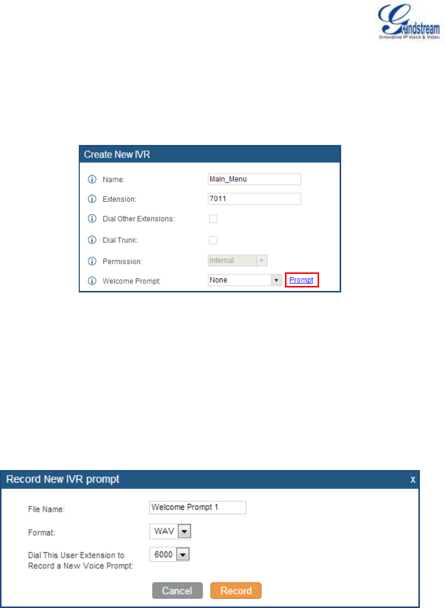
Firmware Version 1.0.0.5
UCM6510 IP PBX User Manual
Page 106 of 192
CREATE IVR PROMPT
To record new IVR prompt or upload IVR prompt to be used in IVR, click on "Prompt" next to the "Welcome
Prompt" option and the users will be redirected to IVR Prompt page. Or users could go to web
GUI->PBX->Internal Options->IVR Prompt page directly.
Figure 37: Click On Prompt To Create IVR Prompt
Once the IVR prompt file is successfully added to the UCM6510, it will be added into the prompt list
options for users to select in different IVR scenarios.
RECORD NEW IVR PROMPT
In the UCM6510 web GUI->PBX->Internal Options->IVR Prompt page, click on "Record New IVR
Prompt" and follow the steps below to record new IVR prompt.
Figure 38: Record New IVR Prompt
Specify the IVR file name.
Select the format (GSM or WAV) for the IVR prompt file to be recorded.
Select the extension to receive the call from the UCM6510 to record the IVR prompt.
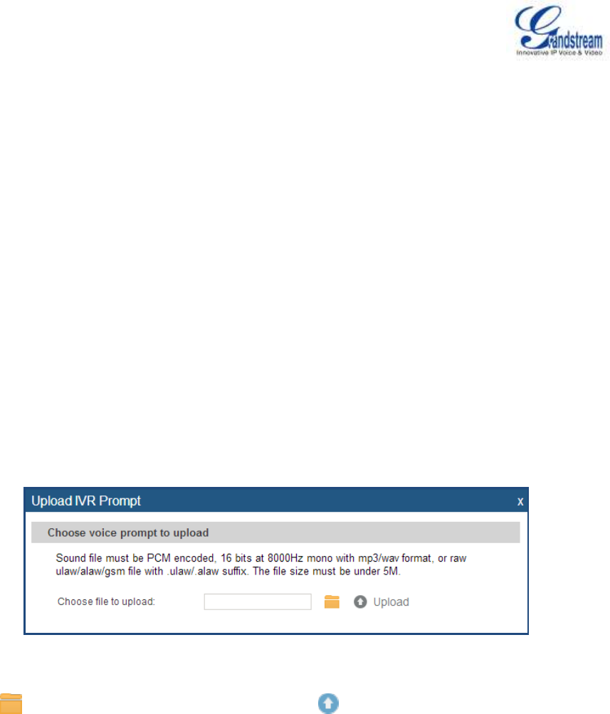
Firmware Version 1.0.0.5
UCM6510 IP PBX User Manual
Page 107 of 192
Click the "Record" button. A request will be sent to the UCM6510. The UCM6510 will then call the
extension for recording the IVR prompt from the phone.
Pick up the call from the extension and start the recording following the voice prompt.
The recorded file will be listed in the IVR Prompt web page. Users could select to re-record, play or
delete the recording.
UPLOAD IVR PROMPT
If the user has a pre-recorded IVR prompt file, click on "Upload IVR Prompt" in web GUI->PBX->Internal
Options->IVR Prompt page to upload the file to the UCM6510. The following are required for the IVR
prompt file to be successfully uploaded and used by the UCM6510:
PCM encoded.
16 bits.
8000Hz mono.
In .mp3 or .wav format; or raw/ulaw/alaw/gsm file with .ulaw or .alaw suffix.
File size under 5M.
Figure 39: Upload IVR Prompt
Click on to select audio file from local PC and click on to start uploading. Once uploaded, the file
will appear in the IVR Prompt web page.

Firmware Version 1.0.0.5
UCM6510 IP PBX User Manual
Page 108 of 192
LANGUAGE SETTINGS FOR VOICE PROMPT
The UCM6510 supports multiple languages in web GUI as well as system voice prompt. The following
languages are currently supported in system voice prompt:
English (United States)
Arabic
Chinese
Dutch
English (United Kingdom)
French
German
Greek
Hebrew
Italian
Polish
Portuguese
Russian
Spanish
Swedish
Turkish
English (United States) and Chinese voice prompts are built in with the UCM6510 already. The other
languages provided by Grandstream can be downloaded and installed from the UCM6510 web GUI directly.
Additionally, users could customize their own voice prompts, package them and upload to the UCM6510.
Language settings for voice prompt can be accessed under web GUI->PBX->Internal
Options->Language.
DOWNLOAD AND INSTALL VOICE PROMPT PACKAGE
To download and install voice prompt package in different languages from UCM6510 web GUI, click on
"Check Prompt List" button.
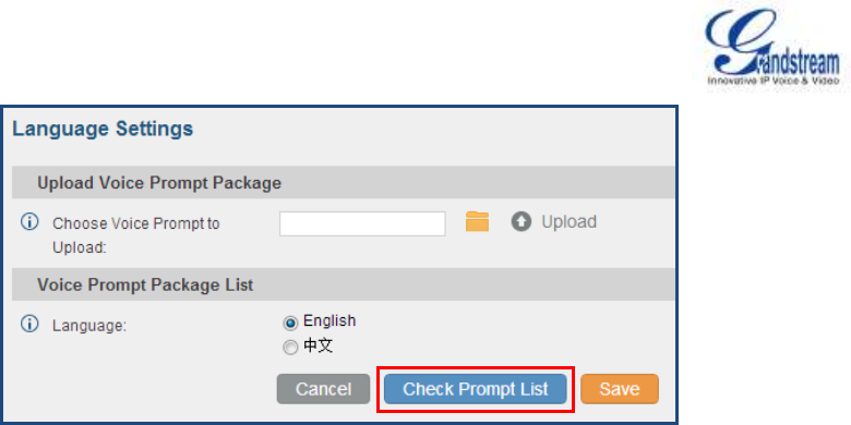
Firmware Version 1.0.0.5
UCM6510 IP PBX User Manual
Page 109 of 192
Figure 40: Language Settings For Voice Prompt
A new dialog window of voice prompt package list will be displayed. Users can see the version number
(latest version available V.S. current installed version), package size and options to upgrade or download
the language.
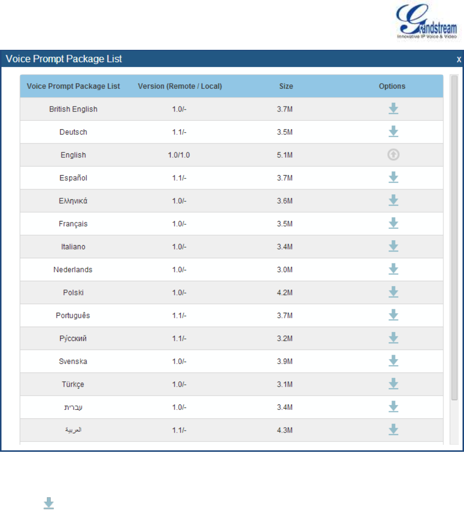
Firmware Version 1.0.0.5
UCM6510 IP PBX User Manual
Page 110 of 192
Figure 41: Voice Prompt Package List
Click on to download the language to the UCM6510. The installation will be automatically started
once the downloading is finished.
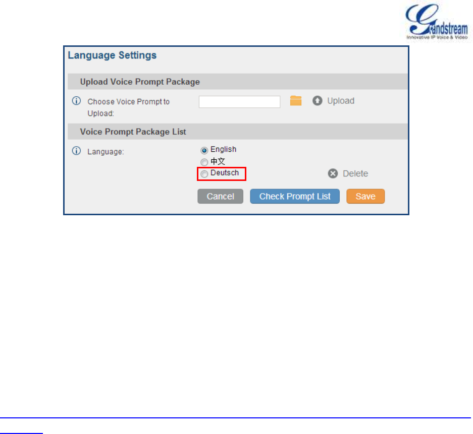
Firmware Version 1.0.0.5
UCM6510 IP PBX User Manual
Page 111 of 192
Figure 42: New Voice Prompt Language Added
A new language option will be displayed after successfully installed. Users then could select it to apply in
the UCM6510 system voice prompt or delete it from the UCM6510.
CUSTOMIZE AND UPLOAD VOICE PROMPT PACKAGE
The UCM6510 provides interface from web GUI for users to customize their own voice prompts. Users
could directly upload the package from web GUI. For detailed instructions on voice prompt customizing
and uploading, please refer to the link below:
http://www.grandstream.com/products/ucm_series/UCM61xx/documents/UCM61xx_voiceprompt_customi
zation.zip

Firmware Version 1.0.0.5
UCM6510 IP PBX User Manual
Page 112 of 192
VOICEMAIL
CONFIGURE VOICEMAIL
If the voicemail is enabled for UCM6510 extensions, the configurations of the voicemail can be globally set
up and managed under web GUI->PBX->Call Features->Voicemail.
Table 34: Voicemail Settings
Max Greeting
Configure the maximum number of seconds for the voicemail greeting.
The default setting is 60 seconds.
Dial '0' For Operator
If enabled, the caller can press 0 to exit the voicemail application and
connect to the configured operator's extension. The operator extension
can be configured under web GUI->PBX->Internal Options->General.
Max Messages Per Folder
Configure the maximum number of messages per folder in users'
voicemail. The valid range 10 to 1000. The default setting is 50.
Max Message Time
Select the maximum duration of the voicemail message. The message
will not be recorded if the duration exceeds the max message time. The
default setting is 15 minutes. The available options are:
1 minute
2 minutes
5 minutes
15 minutes
30 minutes
Unlimited
Min Effective Message Time
Configure the minimum effective duration (in seconds) of a voicemail
message. Messages will be automatically deleted if the duration is
shorter than the Min Effective Message Time. The default setting is 3
seconds. The available options are:
No minimum
1 second
2 seconds
3 seconds
4 seconds
5 seconds
Note:
Silence and noise duration are not counted in message time.
Announce Message Caller-ID
If enabled, the caller ID of the user who has left the message will be
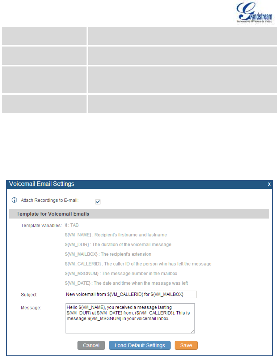
Firmware Version 1.0.0.5
UCM6510 IP PBX User Manual
Page 113 of 192
announced at the beginning of the voicemail message. The default
setting is "No".
Announce Message Duration
If enabled, the message duration will be announced at the beginning of
the voicemail message. The default setting is "No".
Play Envelope
If enabled, a brief introduction (received time, received from, and etc) of
each message will be played when accessed from the voicemail
application. The default setting is "Yes".
Allow User Review
If enabled, users can review the message following the IVR before
sending the message out. The default setting is "No".
VOICEMAIL EMAIL SETTINGS
The UCM6510 can be configured to send the voicemail as attachment to Email. Click on "Voicemail Email
Settings" button to configure the Email attributes and content.
Figure 43: Voicemail Email Settings
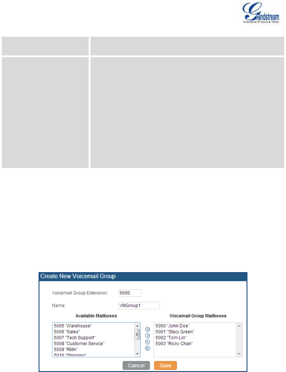
Firmware Version 1.0.0.5
UCM6510 IP PBX User Manual
Page 114 of 192
Table 35: Voicemail Email Settings
Attach Recordings to E-Mail
If enabled, voicemails will be sent to user's Email address. The default
setting is "Yes".
Template For Voicemail Emails
Fill in the "Subject:" and "Message:" content, to be used in the Email
when sending to the user.
The template variables are:
\t: TAB
${VM_NAME}: Recipient's first name and last name
${VM_DUR}: The duration of the voicemail message
${VM_MAILBOX}: The recipient's extension
${VM_CALLERID}: The caller ID of the person who has left the
message
${VM_MSGNUM}: The number of messages in the mailbox
${VM_DATE}: The date and time when the message is left
Click on "Load Default Settings" button to view the default template as an example.
CONFIGURE VOICEMAIL GROUP
The UCM6510 supports voicemail group and all the extensions added in the group will receive the
voicemail to the group extension. The voicemail group can be configured under web GUI->PBX->Call
Features->Voicemail Group. Click on "Create New Voicemail Group" to configure the group.
Figure 44: Voicemail Group

Firmware Version 1.0.0.5
UCM6510 IP PBX User Manual
Page 115 of 192
Table 36: Voicemail Group Settings
Voicemail Group Extension
Enter the Voicemail Group Extension. The voicemail messages left to
this extension will be forwarded to all the voicemail group members.
Name
Configure the Name to identify the voicemail group. Letters, digits, _ and
- are allowed.
Voicemail Group Mailboxes
Select available mailboxes from the left list and add them to the right list.
The extensions need to have voicemail enabled to be listed in available
mailboxes list.
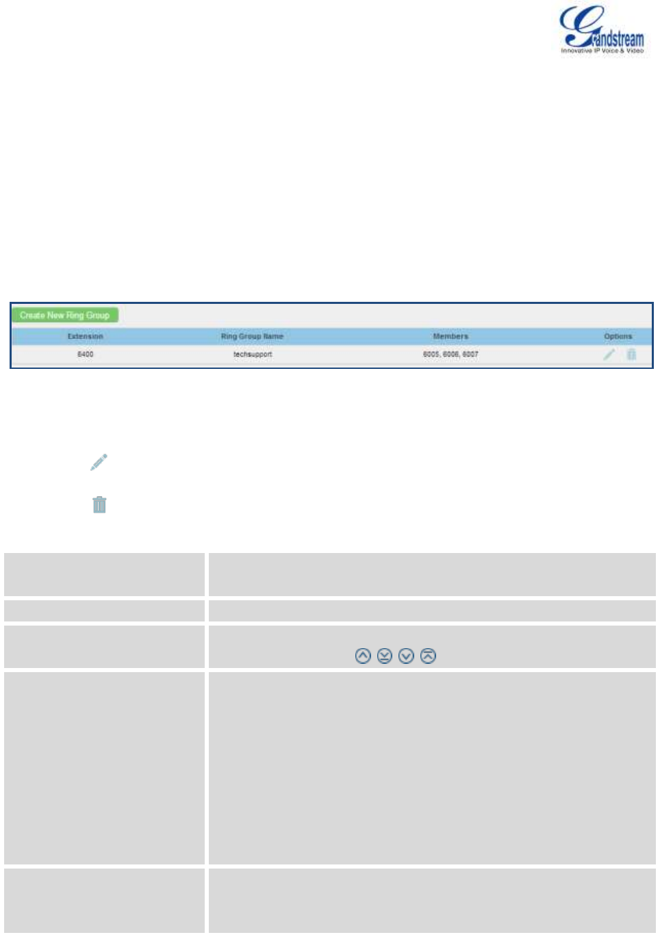
Firmware Version 1.0.0.5
UCM6510 IP PBX User Manual
Page 116 of 192
RING GROUP
The UCM6510 supports ring group feature with different ring strategies applied to the ring group members.
This section describes the ring group configuration on the UCM6510.
CONFIGURE RING GROUP
Ring group settings can be accessed via web GUI->PBX->Call Features->Ring Group.
Figure 45: Ring Group
Click on "Create New Ring Group" to add ring group.
Click on to edit the ring group. The following table shows the ring group configuration parameters.
Click on to delete the ring group.
Table 37: Ring Group Parameters
Ring Group Name
Configure ring group name to identify the ring group. Letters, digits, _
and - are allowed.
Extension
Configure the ring group extension.
Ring Group Members
Select available users from the left side to the ring group member list on
the right side. Click on to arrange the order.
Ring Strategy
Select the ring strategy. The default setting is "Ring in order".
Ring simultaneously
Ring all the members at the same time when there is incoming call
to the ring group extension. If any of the member answers the call, it
will stop ringing.
Ring in order
Ring the members with the order configured in ring group list. If the
first member doesn't answer the call, it will stop ringing the first
member and start ringing the second member.
Ring Timeout on Each Member
Configure the number of seconds to ring each member. If set to 0, it will
keep ringing. The default setting is 30 seconds.
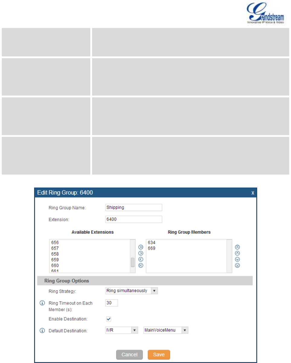
Firmware Version 1.0.0.5
UCM6510 IP PBX User Manual
Page 117 of 192
Note:
The actual ring timeout might be overridden by users if the phone has
ring timeout settings as well.
Enable Destination
If enabled, users could select extension, voicemail, ring group, IVR, call
queue, voicemail group as the destination if the call to the ring group has
no answer. Secret and Email address are required if voicemail is
selected as the destination.
Secret
Configure the password to access the ring group extension's voicemail.
Note:
The password has to be at least 4 characters.
Email Address
Configure the Email address of the ring group extension's voicemail. If
"Attach Recordings to E-mail" is enabled from web
GUI->PBX->Voicemail->Voicemail Email Settings, the voicemail can
be sent to the ring group's Email address as attachment.
Figure 46: Ring Group Configuration
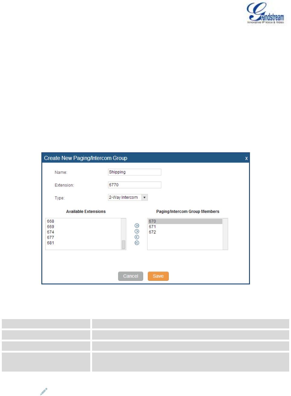
Firmware Version 1.0.0.5
UCM6510 IP PBX User Manual
Page 118 of 192
PAGING AND INTERCOM GROUP
The UCM6510 paging and intercom can be used via feature code to a single extension or a paging/intercom
group. This sections describes the configuration of paging/intercom group under web GUI->PBX->Call
Features->Paging/Intercom.
CONFIGURE PAGING/INTERCOM GROUP
Click on "Create New Paging/Intercom Group" to add paging/intercom group.
Figure 47: Paging/Intercom Group
Table 38: Paging/Intercom Group Configuration Parameters
Name
Configure paging/intercom group name.
Extension
Configure the paging/intercom group extension.
Type
Select "2-way Intercom" or "1-way Page".
Page/Intercom Group
Members
Select available users from the left side to the paging/intercom group
member list on the right.
Click on to edit the paging/intercom group.
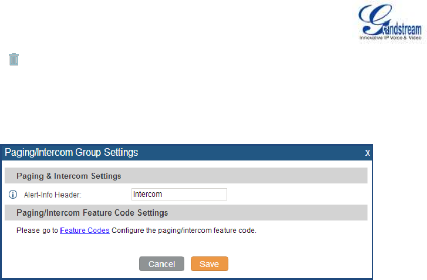
Firmware Version 1.0.0.5
UCM6510 IP PBX User Manual
Page 119 of 192
Click on to delete the paging/intercom group.
Click on "Paging/Intercom Group Settings" to edit Alert-Info Header. This header will be included in the
SIP INVITE message sent to the callee in paging/intercom call.
Figure 48: Page/Intercom Group Settings
The UCM6510 has pre-configured paging/intercom feature code. By default, the Paging Prefix is *81
and the Intercom Prefix is *80. To edit page/intercom feature code, click on "Feature Codes" in the
"Paging/Intercom Group Settings" dialog. Or users could go to web GUI->PBX->Internal
Options->Feature Codes directly.
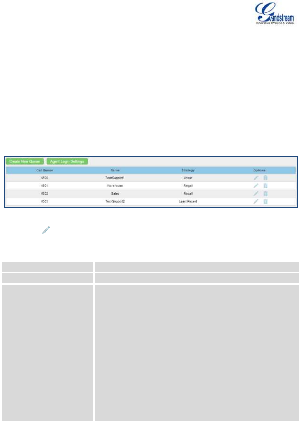
Firmware Version 1.0.0.5
UCM6510 IP PBX User Manual
Page 120 of 192
CALL QUEUE
The UCM6510 supports call queue by using static agents or dynamic agents. This sections describes the
configuration of call queue under web GUI->PBX->Call Features->Call Queue.
CONFIGURE CALL QUEUE
Call queue settings can be accessed via web GUI->PBX->Call Features->Call Queue.
Click on "Create New Queue" to add call queue.
Figure 49: Call Queue
Click on to edit the call queue. The call queue configuration parameters are listed in the table
below.
Table 39: Call Queue Configuration Parameters
Extension
Configure the call queue extension.
Name
Configure the call queue name to identify the call queue.
Strategy
Select the strategy for the call queue.
Ring All
Ring all available Agents simultaneously until one answers.
Linear
Ring agents in the specified order.
Least Recent
Ring the agent who has been called the least recently.
Fewest Calls
Ring the agent with the fewest completed calls.
Random
Ring a random agent.
Round Robin
Ring the agents in Round Robin scheduling with memory.

Firmware Version 1.0.0.5
UCM6510 IP PBX User Manual
Page 121 of 192
The default setting is "Ring All".
Music On Hold
Select the Music On Hold class for the call queue.
Note:
Music On Hold classes can be managed from web GUI-> PBX->Internal
Options->Music On Hold.
Leave When Empty
Configure whether the callers will be disconnected from the queue or not
if the queue has no agent anymore. The default setting is "Strict".
Yes
Callers will be disconnected from the queue if all agents are paused
or invalid.
No
Never disconnect the callers from the queue when the queue is
empty.
Strict
Callers will be disconnected from the queue if all agents are paused,
invalid or unavailable.
Dial in Empty Queue
Configure whether the callers can dial into a call queue if the queue has
no agent. The default setting is "No".
Yes
Callers can always dial into a call queue.
No
Callers cannot dial into a queue if all agents are paused or invalid.
Strict
Callers cannot dial into a queue if the agents are paused, invalid or
unavailable.
Dynamic Login Password
If enabled, the configured PIN number is required for dynamic agent to
log in. The default setting is disabled.
Ring Time Out
Configure the number of seconds an agent will ring before the call goes
to the next agent. The default setting is 15 seconds.
Wrapup Time
Configure the number of seconds before a new call can ring the queue
after the last call on the agent is completed. If set to 0, there will be no
delay between calls to the queue. The default setting is 15 seconds.
Max Queue Length
Configure the maximum number of calls to be queued at once. This
number does not include calls that have been connected with agents. It
only includes calls not connected yet. The default setting is 0, which
means unlimited. When the maximum value is reached, the caller will be
treated with busy tone followed by the next calling rule after attempting
to enter the queue.
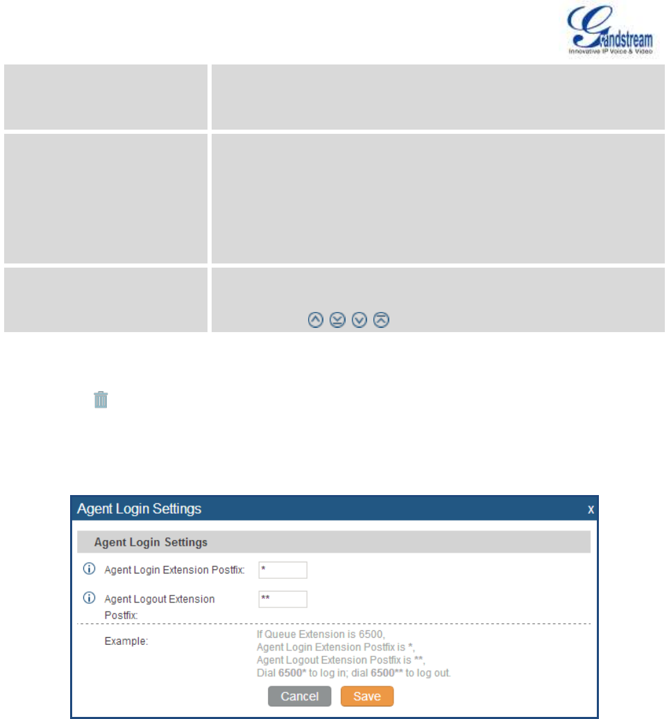
Firmware Version 1.0.0.5
UCM6510 IP PBX User Manual
Page 122 of 192
Report Hold Time
If enabled, the UCM6510 will report (to the agent) the duration of time of
the call before the caller is connected to the agent. The default setting is
"No".
Wait Time
If enabled, users will be disconnected after the configured number of
seconds. The default setting is "No".
Note:
It is recommended to configure "Wait Time" longer than the "Wrapup
Time".
Agents
Select the available users to be the static agents in the call queue.
Choose from the available users on the left to the static agents list on the
right. Click on to arrange the order.
Click on to delete the call queue.
Click on "Agent Login Settings" to configure Agent Login Extension Postfix and Agent Logout
Extension Postfix. Once configured, users could log in the call queue as dynamic agent.
Figure 50: Agent Login Settings
For example, if the call queue extension is 6500, Agent Login Extension Postfix is * and Agent Logout
Extension Postfix is **, users could dial 6500* to login to the call queue as dynamic agent and dial
6500** to logout from the call queue. Dynamic agent doesn't need to be listed as static agent and can
log in/log out at any time.
Call queue feature code "Agent Pause" and "Agent Unpause" can be configured under web
GUI->PBX->Internal Options->Feature Codes. The default feature code is *83 for "Agent Pause"
and *84 for "Agent Unpause".
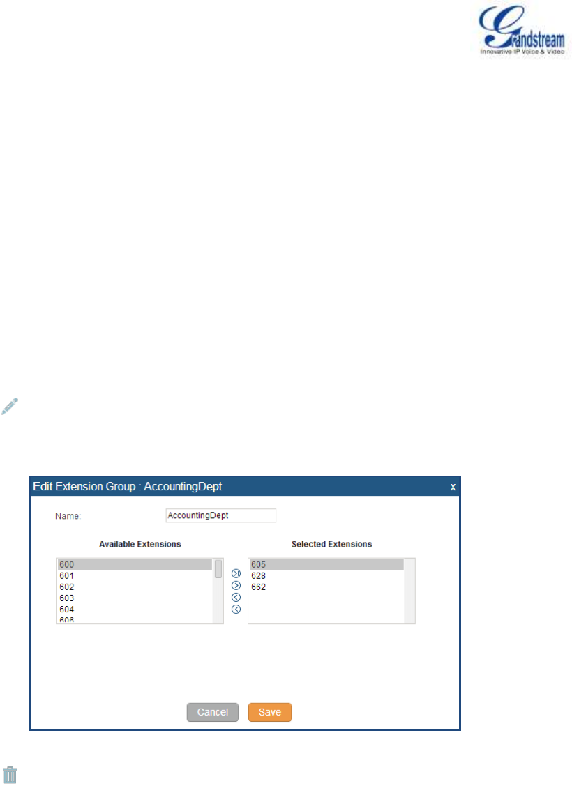
Firmware Version 1.0.0.5
UCM6510 IP PBX User Manual
Page 123 of 192
EXTENSION GROUPS
The UCM6510 extension group feature allows users to assign extensions to different groups to better
manage the configurations on the PBX. For example, when configuring "Enable Filter on Source Caller ID",
users could select a group instead of each person's extension to assign. This feature simplifies the
configuration process and helps manage and categorize the extensions for business environment.
CONFIGURE EXTENSION GROUPS
Extension group can be configured via web GUI->PBX->Call Features->Extension Groups.
Click on "Create New Extension Group" to create a new extension group.
Click on to edit the extension group.
Select extensions from the list on the left side to the right side.
Figure 51: Edit Extension Group
Click on to delete the extension group.
USE EXTENSION GROUPS
Here is an example where the extension group can be used. Go to web GUI->PBX->Basic/Call
Routes->Outbound Routes and select "Enable Filter on Source Caller ID". Both single extensions and
extension groups will show up for users to select.
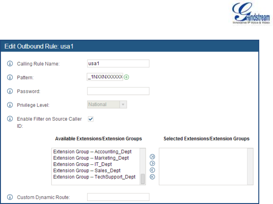
Firmware Version 1.0.0.5
UCM6510 IP PBX User Manual
Page 124 of 192
Figure 52: Select Extension Group in Outbound Route
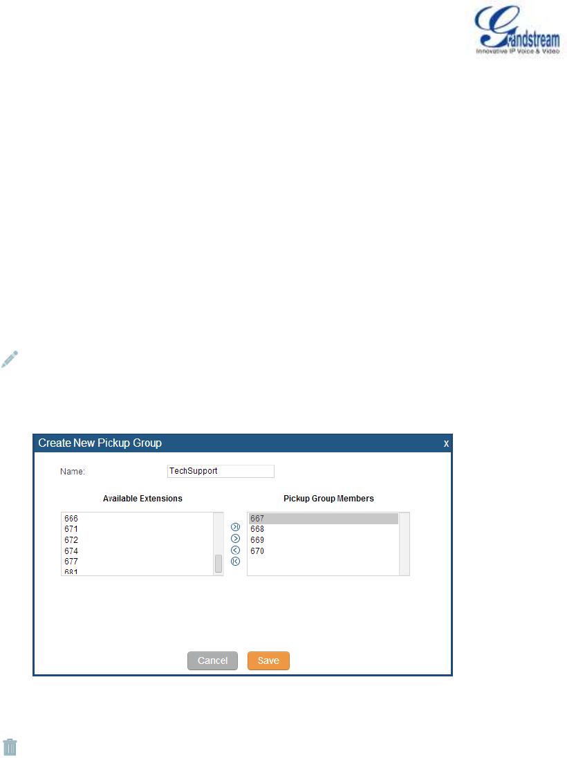
Firmware Version 1.0.0.5
UCM6510 IP PBX User Manual
Page 125 of 192
PICKUP GROUPS
The UCM6510 supports pickup group feature which allows users to pick up incoming calls for other
extensions if they are in the same pickup group, by dialing "Pickup Extension" feature code (by default *8).
CONFIGURE PICKUP GROUPS
Pickup groups can be configured via web GUI->PBX->Call Features->Pickup Groups.
Click on "Create New Pickup Group" to create a new pickup group.
Click on to edit the pickup group.
Select extensions from the list on the left side to the right side.
Figure 53: Edit Pickup Group
Click on to delete the pickup group.
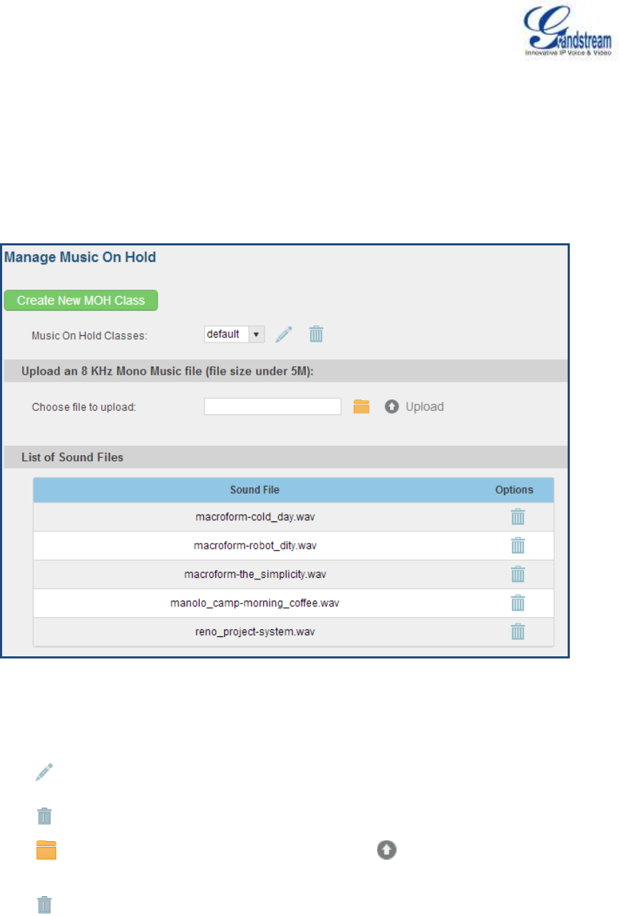
Firmware Version 1.0.0.5
UCM6510 IP PBX User Manual
Page 126 of 192
MUSIC ON HOLD
Music On Hold settings can be accessed via web GUI->PBX->Internal Options->Music On Hold. In this
page, users could configure music on hold class and upload music files. The "default" Music On Hold class
already has 5 audio files defined for users to use.
Figure 54: Music On Hold Default Class
Click on "Create New MOH Class" to add a new Music On Hold class.
Click on to configure the MOH class sort method to be "Alpha" or "Random" for the sound files.
Click on next to the selected Music On Hold class to delete this Music On Hold class.
Click on to select music file from local PC and click on to start uploading. The music file
uploaded has to be 8 KHz Mono format with size smaller than 5M.
Click on next to the sound file to delete it from the selected Music On Hold Class.

Firmware Version 1.0.0.5
UCM6510 IP PBX User Manual
Page 127 of 192
FAX/T.38
The UCM6510 supports T.30/T.38 Fax and Fax Pass-through. It can also convert the received Fax to PDF
format and send it to the configured Email address. Fax/T.38 settings can be accessed via web
GUI->PBX->Internal Options->FAX/T.38.
CONFIGURE FAX/T.38
Click on "Create New Fax Extension". In the popped up window, fill the extension, name and Email
address to send the received Fax to.
Click on "Fax Settings" to configure the Fax parameters.
Table 40: FAX/T.38 Settings
Enable Error Correction Mode
Configure to enable Error Correction Mode (ECM) for the Fax. The
default setting is "Yes".
Maximum Transfer Rate
Configure the maximum transfer rate during the Fax rate negotiation.
The possible values are 2400, 4800, 7200, 9600, 12000 and 14400. The
default setting is 14400.
Minimum Transfer Rate
Configure the minimum transfer rate during the Fax rate negotiation. The
possible values are 2400, 4800, 7200, 9600, 12000 and 14000. The
default setting is 2400.
Default Email Address
Configure the Email address to send the received Fax to if user's Email
address cannot be found.
Note:
The extension's Email address or the Fax's default Email address needs
to be configured in order to receive Fax from Email. If neither of them is
configured, Fax will be not be received from Email.
Template Variables
Fill in the "Subject:" and "Message:" content, to be used in the Email
when sending the Fax to the users.
The template variables are:
${CALLERIDNUM} : Caller ID Number
${CALLERIDNAME} : Caller ID Name
${RECEIVEEXTEN} : The extension to receive the Fax
${FAXPAGES} : Number of pages in the Fax
${VM_DATE} : The date and time when the Fax is received
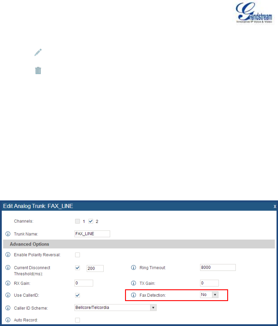
Firmware Version 1.0.0.5
UCM6510 IP PBX User Manual
Page 128 of 192
Click on to edit the Fax extension.
Click on to delete the Fax extension.
SAMPLE CONFIGURATION TO RECEIVE FAX FROM PSTN LINE
The following instructions describes how to use the UCM6510 to receive Fax from PSTN line on the Fax
machine connected to the UCM6510 FXS port.
1. Connect Fax machine to the UCM6510 FXS port.
2. Connect PSTN line to the UCM6510 FXO port.
3. Go to web GUI->PBX->Analog Trunks page.
4. Create or edit the analog trunk for Fax as below.
Fax Detection: Make sure "Fax Detection" option is set to "No".
Figure 55: Configure Analog Trunk without Fax Detection
5. Go to UCM6510 web GUI->PBX->Basic/Call Routes->Extensions page.
6. Create or edit the extension for FXS port.
Analog Station: Select FXS port to be assigned to the extension. By default, it's set to "None".
Once selected, analog related settings for this extension will show up in "Analog Settings"
section.
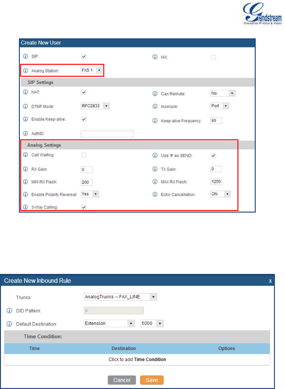
Firmware Version 1.0.0.5
UCM6510 IP PBX User Manual
Page 129 of 192
Figure 56: Configure Extension For Fax Machine
7. Go to web GUI->PBX->Basic/Call Routes->Inbound Routes page.
8. Create an inbound route to use the Fax analog trunk. Select the created extension for Fax machine in
step 4 as the default destination.
Figure 57: Configure Inbound Rule For Fax
Now the Fax configuration is done. When there is an incoming Fax calling to the PSTN number for the
FXO port, it will send the Fax to the Fax machine.
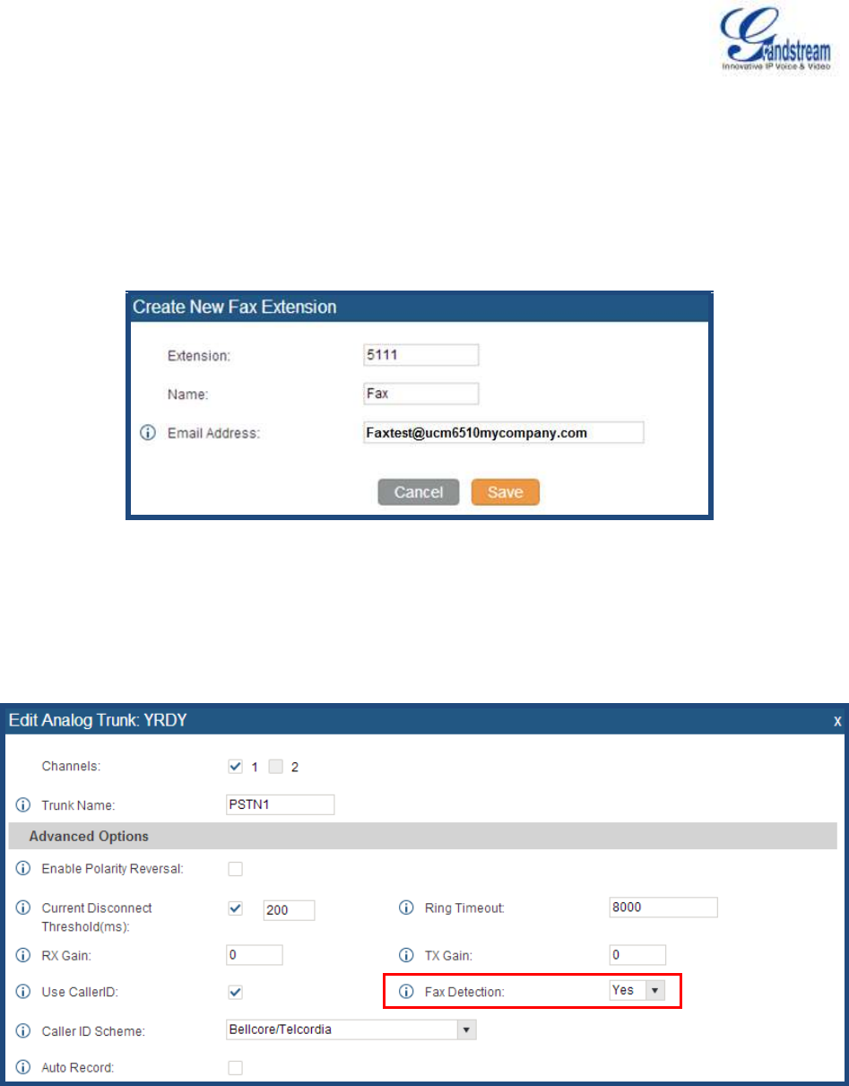
Firmware Version 1.0.0.5
UCM6510 IP PBX User Manual
Page 130 of 192
SAMPLE CONFIGURATION FOR FAX-TO-EMAIL
The following instructions describes a sample configuration on how to use Fax-to-Email feature on the
UCM6510.
1. Connect PSTN line to the UCM6510 FXO port.
2. Go to UCM6510 web GUI->Internal Options->Fax/T.38 page. Create a new Fax extension.
Figure 58: Create Fax Extension
3. Go to UCM6510 web GUI->Basic/Call Routes->Analog Trunks page. Create a new analog trunk.
Please make sure "Fax Detection" is set to "Yes".
Figure 59: Enable Fax Detection In Analog Trunk
4. Go to UCM6510 web GUI->Basic/Call Routes->Inbound Routes page. Create a new inbound route
and set the default destination to the Fax extension.
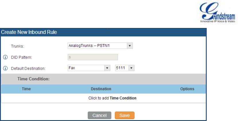
Firmware Version 1.0.0.5
UCM6510 IP PBX User Manual
Page 131 of 192
Figure 60: Inbound Route To Fax Extension
5. Once successfully configured, the incoming Fax from external Fax machine to the PSTN line number
will be converted to PDF file and sent to the Email address Faxtest@ucm6510mycompany.com as
attachment.
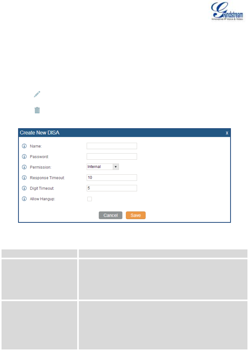
Firmware Version 1.0.0.5
UCM6510 IP PBX User Manual
Page 132 of 192
DISA
The UCM6510 supports DISA to be used in IVR or inbound route. Before using it, create new DISA under
web GUI->Call Features->DISA.
Click on "Create New IVR" to add a new DISA.
Click on to edit the DISA configuration.
Click on to delete the DISA.
Figure 61: Create New DISA
Table 41: DISA Settings
Name
Configure DISA name to identify the DISA.
Password
Configure the password (digit only) required for the user to enter before
using DISA to dial out.
Note:
The password has to be at least 4 digits.
Permission
Configure the permission level for DISA. The available permissions are
"Internal", "Local", "National" and "International" from the lowest level to
the highest level. The default setting is "Internal". If the user tries to dial
outbound calls after dialing into the DISA, the UCM6510 will compared
the DISA's permission level with the outbound route's privilege level. If
the DISA's permission level is higher than (or equal to) the outbound

Firmware Version 1.0.0.5
UCM6510 IP PBX User Manual
Page 133 of 192
route's privilege level, the call will be allowed to go through.
Response Timeout
Configure the maximum amount of time the UCM6510 will wait before
hanging up if the user dials an incomplete or invalid number. The default
setting is 10 seconds.
Digit Timeout
Configure the maximum amount of time permitted between digits when
the user is typing the extension. The default setting is 5 seconds.
Allow Hangup
If enabled, during an active call, users can enter the UCM6510 hangup
feature code (by default it's *0) to disconnect the call or hang up directly.
A new dial tone will be heard shortly for the user to make a new call. The
default setting is "No".
Once successfully created, users can configure the inbound route destination as "DISA" or IVR key event
as "DISA". When dialing into DISA, users will be prompted with password first. After entering the correct
password, a second dial tone will be heard for the users to dial out.
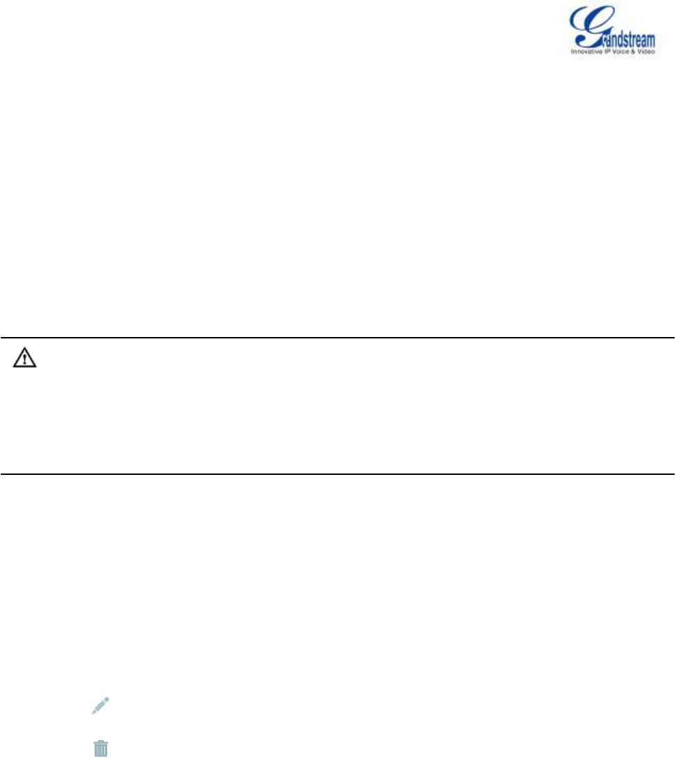
Firmware Version 1.0.0.5
UCM6510 IP PBX User Manual
Page 134 of 192
BLF AND EVENT LIST
BLF
The UCM6510 supports BLF monitoring for extensions, ring group, call queue, conference room and
parking lot. For example, on the user's phone, configure the parking lot number 701 as the BLF monitored
number. When there is a parked call on 701, the LED for this BLF key will light up in red, meaning a call is
parked against this parking lot. Pressing this BLF key can pick up the call from this parking lot.
Note:
On the Grandstream GXP phones, the MPK supports "Call Park" mode, which is normally used to park
the call by configuring the MPK number as call park feature code (e.g., 700). Users could also use
"Call Park" mode to monitor and pick up the call on this parking lot by configuring the MPK number as
parking lot number (e.g., 701).
EVENT LIST
Besides BLF, users can also configure the phones to monitor event list. In this way, both local extensions
on the same UCM6510 or remote extensions on the peer SIP trunk can be monitored. The event list
settings is under web GUI->Call Features->Event List.
Click on "Create New Event List" to add a new event list.
Click on to edit the event list configuration.
Click on to delete the event list.
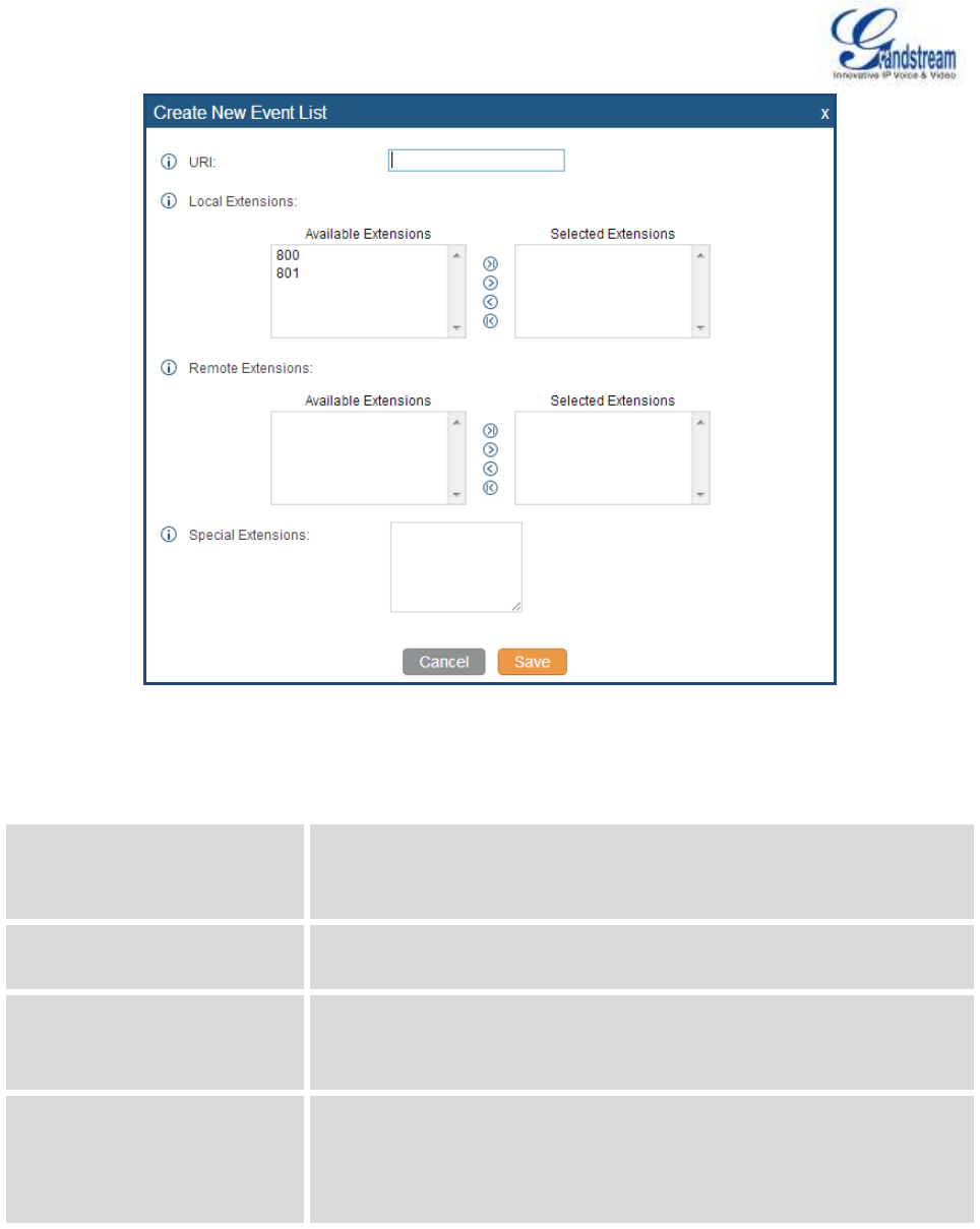
Firmware Version 1.0.0.5
UCM6510 IP PBX User Manual
Page 135 of 192
Figure 62: Create New Event List
Table 42: Event List Settings
URI
Configure the name of this event list (for example, office_event_list).
Please note the URI name cannot be the same as the extension name
on the UCM6510. The valid characters are letters, digits, _ and -.
Local Extensions
Select the available extensions listed on the local UCM6510 to be
monitored in the event list.
Remote Extensions
If LDAP sync is enabled between the UCM6510 and the peer UCM6510,
the remote extensions will be listed under "Available Extensions". If not,
manually enter the remote extensions under "Special Extensions" field.
Special Extensions
Manually enter the remote extensions in the peer/register trunk to be
monitored in the event list.
Valid format: 5000,5001,9000
Remote extension monitoring works on the UCM6510 via event list BLF, among Peer SIP trunks or
Register SIP trunks (register to each other). Therefore, please properly configure SIP trunks on the

Firmware Version 1.0.0.5
UCM6510 IP PBX User Manual
Page 136 of 192
UCM6510 first before using remote BLF feature. Please note the SIP end points need support event list
BLF in order to monitor remote extensions.
When an event list is created on the UCM6510 and remote extensions are added to the list, the UCM6510
will send out SIP SUBSCIRBE to the remote UCM6510 to obtain the remote extension status. When the
SIP end points registers and subscribes to the local UCM6510 event list, it can obtain the remote
extension status from this event list.
Once successfully configured, the event list page will show the status of total extension and subscribers for
each event list. Users can also select the event URI to check the monitored extension's status and the
subscribers' details.
Note:
To configure LDAP sync, please go to UCM6510 web GUI->PBX->Basic/Call Routes->VoIP Trunk.
You will see "Sync LDAP Enable" option. Once enabled, please configure password information for
the remote peer UCM6510 to connect to the local UCM6510. Additional information such as port
number, LDAP outbound rule, LDAP Dialed Prefix will also be required. Both the local UCM6510 and
remote UCM6510 need enable LDAP sync option with the same password for successful connection
and synchronization.
Currently LDAP sync feature only works between two UCM6510s.
(Theoretically) Remote BLF monitoring will work when the remote PBX being monitored is
non-UCM6510 PBX. However, it might not work the other way around depending on whether the
non-UCM6510 PBX supports event list BLF or remote monitoring feature.
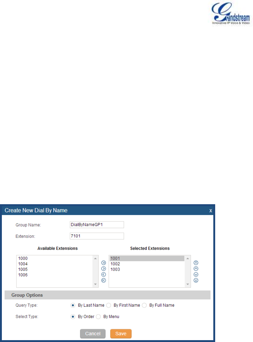
Firmware Version 1.0.0.5
UCM6510 IP PBX User Manual
Page 137 of 192
DIAL BY NAME
Dial By Name is a feature on the PBX that allows caller to search a person by first or last name via his/her
phone's keypad. The administrator can define the Dial By Name directory including the desired extensions
in the directory and the searching type by "first name" or "last name". After dialing in, the PBX IVR/Auto
Attendant will guide the caller to spell the digits to find the person in the Dial By Name directory. This feature
allows customers/clients to use the guided automatic system to get in touch with the enterprise employees
without having to know the extension number, which brings convenience and improves business image for
the enterprise.
DIAL BY NAME CONFIGURATION
The administrators can create the dial by name group under web GUI->PBX->Call Features->Dial By
Name.
Figure 63: Create Dial By Name Group
1. Group Name
Enter the Group Name. This is to identify the Dial By Name group. The Dial By Name group can be
used as the destination for inbound route and key pressing event for IVR. The group name defined here
will show up in the destination list when configuring IVR and inbound route.
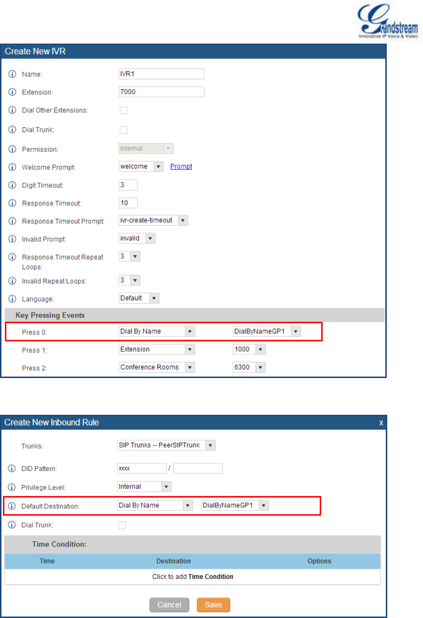
Firmware Version 1.0.0.5
UCM6510 IP PBX User Manual
Page 138 of 192
Figure 64: Dial By Name Group In IVR Key Pressing Events
Figure 65: Dial By Name Group In IVR Key Pressing Events
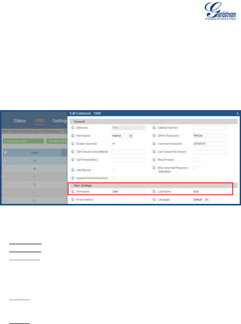
Firmware Version 1.0.0.5
UCM6510 IP PBX User Manual
Page 139 of 192
2. Extension
Configure the direct dial extension for the Dial By Name group.
3. Available Extensions/Selected Extensions
Select available extensions from the left side to the right side as the directory for the Dial By Name
group. Only the selected extensions here can be reached by the Dial By Name IVR when dialing into
this group. The extensions here must have valid first name and last name configured under web
GUI->PBX->Basic/Call Routes->Extensions in order to be searchable in Dial By Name directory
through IVR. By specifying the extensions here, the administrators can make sure unscreened calls will
not reach the company employee if he/she doesn't want to receive them directly.
Figure 66: Configure Extension First Name And Last Name
4. Query Type
Specify the query type. This defines how the caller will need to enter to search the directory.
By First Name: enter the first 3 digits of the first name to search the directory.
By Last Name: enter the first 3 digits of the last name to search the directory.
By Full Name: enter the first 3 digits of the first name or last name to search the directory.
5. Select Type
Specify the select type on the searching result. The IVR will confirm the name/number for the party the
caller would like to reach before dialing out
By Order: After the caller enters the digits, the IVR will announce the first matching party's name and
number. The caller can confirm and dial out if 's the destination party, or press * to listen to the next
matching result if it's not the desired party to call.
By Menu: After the caller enters the digits, the IVR will announce 8 matching results. The caller can
press number 1 to 8 to select and call, or press 9 for results in next page.

Firmware Version 1.0.0.5
UCM6510 IP PBX User Manual
Page 140 of 192
CALL FEATURES
The UCM6510 supports call recording, transfer, call forward, call park and other call features via feature
code. This section lists all the feature codes in the UCM6510 and describes how to use the call features.
FEATURE CODES
Table 43: UCM6510 Feature Codes
Feature Maps
Blind Transfer
Default code: #1.
Enter the code during active call. After hearing "Transfer", you
will hear dial tone. Enter the number to transfer to. Then the
user will be disconnected and transfer is completed.
Options
Disable
Allow Caller: Enable the feature code on caller side only.
Allow Callee: Enable the feature code on callee side only.
Allow Both: Enable the feature code on both caller and
callee.
Attended Transfer
Default code: *2.
Enter the code during active call. After hearing "Transfer", you
will hear the dial tone. Enter the number to transfer to and the
user will be connected to this number. Hang up the call to
complete the attended transfer.
Options
Disable
Allow Caller: Enable the feature code on caller side only.
Allow Callee: Enable the feature code on callee side only.
Allow Both: Enable the feature code on both caller and
callee.
Disconnect
Default code: *0.
Enter the code during active call. It will disconnect the call.
Options
Disable
Allow Caller: Enable the feature code on caller side only.
Allow Callee: Enable the feature code on callee side only.
Allow Both: Enable the feature code on both caller and

Firmware Version 1.0.0.5
UCM6510 IP PBX User Manual
Page 141 of 192
callee.
Call Park
Default code: #72.
Enter the code during active call to park the call.
Options
Disable
Allow Caller: Enable the feature code on caller side only.
Allow Callee: Enable the feature code on callee side only.
Allow Both: Enable the feature code on both caller and
callee.
Audio Mix Record
Default code: *3.
Enter the code followed by # or SEND to start recording the
audio call and the UCM6510 will mix the streams natively on
the fly as the call is in progress.
Options
Disable
Allow Caller: Enable the feature code on caller side only.
Allow Callee: Enable the feature code on callee side only.
Allow Both: Enable the feature code on both caller and
callee.
DND/Call Forward
Do Not Disturb (DND) Activate
Default code: *77.
Do Not Disturb (DND) Deactivate
Default code: *78.
Call Forward Busy Activate
Default Code: *90.
Enter the code and follow the voice prompt. Or enter the code
followed by the extension to forward the call.
Call Forward Busy Deactivate
Default Code: *91.
Call Forward No Answer Activate
Default Code: *92.
Enter the code and follow the voice prompt. Or enter the code
followed by the extension to forward the call.
Call Forward No Answer
Deactivate
Default Code: *93.
Call Forward Unconditional
Activate
Default Code: *72.
Enter the code and follow the voice prompt. Or enter the code
followed by the extension to forward the call.
Call Forward Unconditional
Deactivate
Default Code: *73.
Feature Misc
Feature Code Digits Timeout
Default Setting: 1000.

Firmware Version 1.0.0.5
UCM6510 IP PBX User Manual
Page 142 of 192
Configure the maximum interval (in milliseconds) between the
digits input to activate the feature code.
Call Park
Default Extension: 700.
During an active call, initiate blind transfer and then enter this
code to park the call.
Parked Lots
Default Extension: 701-720.
These are the extensions where the calls will be parked, i.e.,
parking lots that the parked calls can be retrieved.
Parking Timeout (s)
Default setting: 300.
This is the timeout allowed for a call to be parked. After the
timeout, if the call is not picked up, the extension who parks
the call will be called back.
Feature Codes
Voicemail Access Code
Default Code: *98.
Enter *98 and follow the voice prompt. Or dial *98 followed by
the extension and # to access the entered extension's
voicemail box.
My Voicemail
Default Code: *97.
Press *97 to access the voicemail box.
Agent Pause
Default Code: *83.
Pause the agent in all call queues.
Agent Unpause
Default Code: *84.
Unpause the agent in all call queues.
Paging Prefix
Default Code: *81.
To page an extension, enter the code followed by the
extension number.
Intercom Prefix
Default Code: *80.
To intercom an extension, enter the code followed by the
extension number.
Blacklist Add
Default Code: *40.
To add a number to blacklist for inbound route, dial *40 and
follow the voice prompt to enter the number.
Blacklist Remove
Default Code: *41.
To remove a number from current blacklist for inbound route,
dial *41 and follow the voice prompt to remove the number.
Call Pickup on Ringing
Default Code: **.
To pick up a call for any extension xxxx, enter the code
followed by the extension number xxxx.
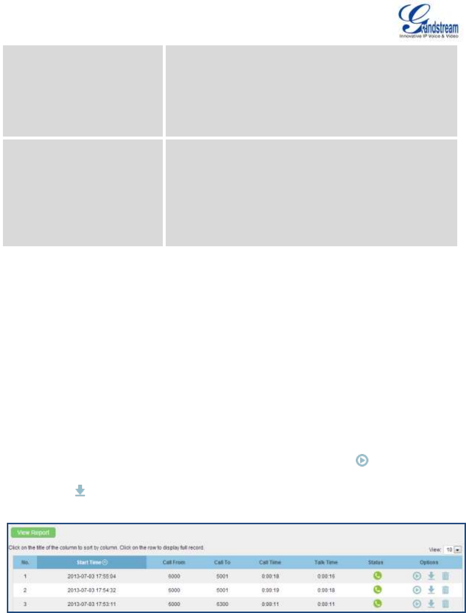
Firmware Version 1.0.0.5
UCM6510 IP PBX User Manual
Page 143 of 192
Pickup Extension
Default Code: *8.
This code is for the pickup group which can be assigned for
each extension on the extension configuration page.
If there is an incoming call to an extension, the other
extensions within the same pickup group can dial *8 directly to
pick up the call.
Direct Dial Voicemail Prefix
Default Code: *
This code is for the user to directly dial or transfer to an
extension's voicemail.
For example, directly dial *5000 will have to call go into the
extension 5000's voicemail. If the user would like to transfer
the call to the extension 5000's voicemail, enter *5000 as the
transfer target number.
CALL RECORDING
The UCM6510 allows users to record audio during the call. If "Auto Record" is turned on for extension or
trunk, the call will be automatically recorded when there is established call with the extension or trunk.
Otherwise, please follow the instructions below to manually record the call.
1. Make sure the feature code for "Audio Mix Record" is configured and enabled.
2. After establishing the call, enter the "Audio Mix Record" feature code (by default it's *3) followed by # or
SEND to start recording.
3. To stop the recording, enter the "Audio Mix Record" feature code (by default it's *3) followed by # or
SEND again. Or the recording will be stopped once the call hangs up.
4. The recording file can be retrieved under web GUI->Status->CDR. Click on to play the recording
or click on to download the recording file.
Figure 67: Download Recording File From CDR Page

Firmware Version 1.0.0.5
UCM6510 IP PBX User Manual
Page 144 of 192
The above recorded call's recording files are also listed under the UCM6510 web GUI->CDR->Recording
Files.
CALL PARK
The UCM6510 provides call park and call pickup features via feature code.
PARK A CALL
There are two feature codes that can be used to park the call.
Feature Maps->Call Park (Default code #72)
During an active call, press #72 and the call will be parked. Parking lot number (default range 701 to
720) will be announced after parking the call.
Feature Misc->Call Park (Default code 700)
During an active call, initiate blind transfer (default code #1) and then dial 700 to park the call. Parking
lot number (default range 701 to 720) will be announced after parking the call.
RETRIEVE THE PARKED CALL
To retrieve the parked call, simply dial the parking lot number and the call will be established. If a parked call
is not retrieved after the timeout, the original extension who parks the call will be called back.

Firmware Version 1.0.0.5
UCM6510 IP PBX User Manual
Page 145 of 192
INTERNAL OPTIONS
This section describes internal options that haven't been mentioned in previous sections yet. The settings in
this section can be applied globally to the UCM6510, including general configurations, jitter buffer, RTP
settings, hardware config and STUN monitor. The options can be accessed via web GUI->PBX->Internal
Options.
INTERNAL OPTIONS/GENERAL
Table 44: Internal Options/General
General Preferences
Global OutBound CID
Configure the global CallerID used for all outbound calls when no other
CallerID is defined with higher priority. If no CallerID is defined for
extension or trunk, the global outbound CID will be used as CallerID.
Global OutBound CID Name
Configure the global CallerID Name used for all outbound calls. If
configured, all outbound calls will have the CallerID Name set to this
name. If not, the extension's CallerID Name will be used.
Operator Extension
Specify the operator extension, which will be dialed when users presses
0 to exit voicemail application. The operator extension can also be used
in IVR option.
Ring Timeout
Configure the number of seconds to ring an extension before the call
goes to the user's voicemail box. The default setting is 60.
Note:
This is the global value used for each extension if "Ring Timeout" field is
left empty on the extension configuration page.
Record Prompt
If enabled, users will hear voice prompt before recording is started or
stopped. For example, before recording, the UCM6510 will play voice
prompt "The call will be recorded". The default setting is "No".
Extension Preferences
Enforce Strong Passwords
If enabled, strong password will be enforced for the password created on
the UCM6510. The default setting is enabled.
Strong Password Rules:
1. Password for voicemail, voicemail group, outbound route, DISA,
password, call queue and conference requires non-repetitive and
non-sequential digits, with a minimum length of 4 digits. Repetitive

Firmware Version 1.0.0.5
UCM6510 IP PBX User Manual
Page 146 of 192
digits pattern (such as 0000, 1111, 1234, 2345, and etc), or common
digits pattern (such as 111222, 321321 and etc) are not allowed to be
configured as password.
2. Password for extension registration, web GUI admin login, LDAP and
LDAP sync requires alphanumeric characters containing at least
two categories of the following, with a minimum length of 4
characters.
Numeric digits
Lowercase alphabet characters
Uppercase alphabet characters
Special characters
Enable Random Password
If enabled, random password will be generated when the extension is
created. The default setting is "Yes". It is recommended to enable it for
security purpose.
Disable Extension Range
If set to "Yes", users could disable the extension range
pre-configured/configured on the UCM6510. The default setting is "No".
The default extension range assignment is:
User Extensions: 1000-6299
Pick Extensions: 4000-4999
Auto Provision Extensions: 5000-6299
Conference Extensions: 6300-6399
Ring Group Extensions: 6400-6499
Queue Extensions: 6500-6599
Voicemail Group Extensions: 6600-6699
IVR Extensions: 7000-7100
Fax Extensions: 7200-8200
Note:
It is recommended to keep the system assignment to avoid
inappropriate usage and unnecessary issues.
INTERNAL OPTIONS/JITTER BUFFER
Table 45: Internal Options/Jitter Buffer
SIP Jitter Buffer
Enable Jitter Buffer
Select to enable jitter buffer on the sending side of the SIP channel. The
default setting is "No".

Firmware Version 1.0.0.5
UCM6510 IP PBX User Manual
Page 147 of 192
Jitter Buffer Size
Configure the time (in ms) to buffer. This is the jitter buffer size used in
"Fixed" jitter buffer, or used as the initial time for "adaptive" jitter buffer.
The default setting is 100.
Max Jitter Buffer
Configure the maximum time (in ms) to buffer for "Adaptive" jitter buffer
implementation, or used as the jitter buffer size for "Fixed" jitter buffer
implementation. The default setting is 200.
Implementation
Configure the jitter buffer implementation on the sending side of a SIP
channel. The default setting is "Fixed".
Fixed
The size is always equal to the value of "Max Jitter Buffer".
Adaptive
The size is adjusted automatically and the maximum value equals to
the value of "Max Jitter Buffer".
INTERNAL OPTIONS/RTP SETTINGS
Table 46: Internal Options/RTP Settings
RTP Start
Configure the RTP port starting number. The default setting is 10000.
RTP End
Configure the RTP port ending address. The default setting is 20000.
Strict RTP
Configure to enable or disable strict RTP protection. If enabled, RTP
packets that do not come from the source of the RTP stream will be
dropped. The default setting is "Disable".
RTP Checksums
Configure to enable or disable RTP Checksums on RTP traffic. The
default setting is "Disable".
INTERNAL OPTIONS/STUN MONITOR
Table 47: Internal Options/STUN Monitor
STUN Server
Configures the IP address or URL of the STUN server to query. If not
specified, STUN is disabled. The default setting is stun.ipvideotalk.com.
Valid format:
[(hostname | IP-address) [':' port]
The default port number is 3478 if not specified.
STUN Refresh
Configure the number of seconds between STUN Refreshes. The
default setting is 30 seconds.

Firmware Version 1.0.0.5
UCM6510 IP PBX User Manual
Page 148 of 192
IAX SETTINGS
The UCM6510 IAX global settings can be accessed via web GUI->PBX->IAX Settings.
IAX SETTINGS/GENERAL
Table 48: IAX Settings/General
Bind Port
Configure the port number that the IAX2 will be allowed to listen to. The
default setting is 4569.
Bind Address
Configure the address that the IAX2 will be forced to bind to. The default
setting is 0.0.0.0, which means all addresses.
IAX1 Compatibility
Select to configure IAX1 compatibility. The default setting is "No".
No Checksums
If selected, UDP checksums will be disabled and no checksums will be
calculated/checked on systems supporting this features. The default
setting is "No".
Delay Reject
If enabled, the IAX2 will delay the rejection of calls to avoid DOS. The
default setting is "No".
ADSI
Select to enable ADSI phone compatibility. The default setting is "No".
Music On Hold Interpret
Specify which Music On Hold class this channel would like to listen to
when being put on hold. This music class is only effective if this channel
has no music class configured and the bridged channel putting the call
on hold has no "Music On Hold Suggest" setting.
Music On Hold Suggest
Specify which Music On Hold class to suggest to the bridged channel
when putting the call on hold.
Bandwidth
Configure the bandwidth for IAX settings. The default setting is "Low".
IAX SETTINGS/REGISTRATION
Table 49: IAX Settings/Registration
IAX Registration Options
Min Reg Expire
Configure the minimum period (in seconds) of registration. The default
setting is 60.
Max Reg Expire
Configure the maximum period (in seconds) of registration. The default
setting is 3600.
IAX Thread Count
Configure the number of IAX helper threads. The default setting is 10.
IAX Max Thread Count
Configure the maximum number of IAX threads allowed. The default

Firmware Version 1.0.0.5
UCM6510 IP PBX User Manual
Page 149 of 192
setting is 100.
Auto Kill
If set to "yes", the connection will be terminated if ACK for the NEW
message is not received within 2000ms. Users could also specify
number (in milliseconds) in addition to "yes" and "no". The default setting
is "yes".
Authentication Debugging
If enabled, authentication traffic in debugging will not show. The default
setting is "No".
Codec Priority
Configure codec negotiation priority. The default setting is "Reqonly".
Caller
Consider the callers preferred order ahead of the host's.
Host
Consider the host's preferred order ahead of the caller's.
Disabled
Disable the consideration of codec preference all together.
Reqonly
This is almost the same as "Disabled", except when the requested
format is not available. The call will only be accepted if the
requested format is available.
Type of Service
Configure ToS bit for preferred IP routing.
IAX Trunk Options
Trunk Frequency
Configure the frequency of trunk frames (in milliseconds). The default
setting is 20.
Trunk Time Stamps
If enabled, time stamps will be attached to trunk frames. The default
setting is "No".
IAX SETTINGS/STATIC DEFENSE
Table 50: IAX Settings/Static Defense
Call Token Optional
Enter a single IP address or a range of IP addresses for which call token
validation is not required.
For example:
11.11.11.11
11.11.11.11/22.22.22.22.
Max Call Numbers
Configure the maximum number of calls allowed for a single IP address.
Max Unvalidated Call Numbers
Configure the maximum number of unvalidated calls for all IP
addresses.
Call Number Limits
Configure to limit the number of calls for a give IP address of IP range.

Firmware Version 1.0.0.5
UCM6510 IP PBX User Manual
Page 150 of 192
IP or IP Range
Enter the IP address or a range of IP addresses to be considered for call
number limits.
For example:
11.11.11.11
11.11.11.11/22.22.22.22.

Firmware Version 1.0.0.5
UCM6510 IP PBX User Manual
Page 151 of 192
SIP SETTINGS
The UCM6510 SIP global settings can be accessed via web GUI->PBX->SIP Settings.
SIP SETTINGS/GENERAL
Table 51: SIP Settings/General
Realm For Digest
Authentication
Configure the host name or domain name for the UCM6510. Realms
MUST be globally unique according to RFC3261. The default setting is
Grandstream.
Bind UDP Port
Configure the UDP port used for SIP. The default setting is 5060.
Bind IP Address
Configure the IP address to bind to. The default setting is 0.0.0.0, which
means binding to all addresses.
Allow Guest Calls
If enabled, the UCM6510 allows unauthorized INVITE coming into the
PBX and the call can be made. The default setting is "No".
Warning:
Please be aware of the potential security risk when enabling "Allow
Guest Calls" as this will allow any user with the UCM6510 address to
dial into the UCM6510.
Overlap Dialing
Select to enable overlap dialing support. Overlap dial provides for a
longer time-out period between digits, also called the inter-digit timer. If
set to "Yes", the PBX expects to receive the digits one right after the
other coming in to this line with very little delay between digits. If set to
"No", the PBX waits up to about 2 seconds between digits. The default
setting is "No".
Allow Transfer
If set to "No", all transfers initiated by the endpoint in the UCM6510 will
be disabled (unless enabled in peers or users). The default setting is
"Yes".
Enable DNS SRV Lookups on
Outbound Calls
Select to enables DNS SRV lookups on outbound calls from the
UCM6510. The default setting is "Yes".
MWI From
When sending MWI NOTIFY requests, this value will be used in the
"From:" header as the "name" field. If no "From User" is configured, the
"user" field of the URI in the "From:" header will be filled with this value.
SIP Domain Support
Domain
Configure the domain for the UCM6510. Incoming INVITE and REFER
messages can be matched against a list of "allowed" domains, each of

Firmware Version 1.0.0.5
UCM6510 IP PBX User Manual
Page 152 of 192
which can direct the call to a specific context if desired. By default, all
domains are accepted and sent to the default context or the context
associated with the user/peer placing the call. Register to non-local
domains will be automatically denied if a domain list is configured. Up to
10 domains can be added.
From Domain
Configure the domain in the "From:" header of the SIP message. It may
be required by some providers for authentication.
Auto Domain
If enabled, the UCM6510 will add local host name and local IP to domain
list. The default setting is "No".
Allow External Domains
If enabled, requests for external domains that are not served by the
UCM6510 will be allowed. The default setting is "Yes".
SIP SETTINGS/MISC
Table 52: SIP Settings/Misc
Outbound SIP Registrations
Register Timeout
Configure the register retry timeout (in seconds). The default setting is
20.
Register Attempts
Configure the number of registration attempts before the UCM6510
gives up. The default setting is 0, which means the UCM6510 will keep
trying until the server side accepts the registration request.
Video
Max Bit Rate (kb/s)
Configure the maximum bit rate (in kb/s) for video calls. The default
setting is 384.
Support SIP Video
Select to enable video support in SIP calls. The default setting is "Yes".
Generate Manager Events
If enabled, the UCM6510 will generate manager events when SIP UA
performs events (e.g. Hold). The default setting is "No".
Reject Non-Matching INVITE
If enabled, when rejecting an incoming INVITE or REGISTER request,
the UCM6510 will always reject with "401 Unauthorized" instead of
notifying the requester whether there is a matching user or peer for the
request. This reduces the ability of an attacker to scan for valid SIP
usernames. The default setting is "No".
SIP SETTINGS/SESSION TIMER
Table 53: SIP Settings/Session Timer
Session Timers
Select the session timer mode. The default setting is "Accept".
The options are:

Firmware Version 1.0.0.5
UCM6510 IP PBX User Manual
Page 153 of 192
Originate
Always request and run session timer.
Accept
Run session timer only when requested by other UA.
Refuse
Do not run session timer.
Session Expire
Configure the maximum session refresh interval (in seconds). The
default setting is 1800.
Min SE
Configure the minimum session refresh interval (in seconds). The
default setting is 90.
Session Refresher
Select the session refresher to be UAC or UAS. The default setting is
UAC.
SIP SETTINGS/TCP and TLS
Table 54: SIP Settings/TCP and TLS
TCP Enable
Configure to allow incoming TCP connections with the UCM6510. The
default setting is "No".
TCP Bind Address
Configure the IP address for TCP server to bind to. 0.0.0.0 means
binding to all interfaces. The port number is optional. If not specified,
5060 will be used.
TLS Enable
Configure to allow incoming TLS connections with the UCM6510. The
default setting is "No".
TLS Bind Address
Configure the IP address for TLS server to bind to. 0.0.0.0 means
binding to all interfaces. The port number is optional. If not specified,
5061 will be used.
Note:
The IP address must match the common name (hostname) in the
certificate. Please do not bind a TLS socket to multiple IP addresses.
For details on how to construct a certificate for SIP, please refer to the
following document:
http://tools.ietf.org/html/draft-ietf-sip-domain-certs
TLS Client Protocol
Select the TLS protocol for outbound client connections. The default
setting is TLSv1.
TLS Do Not Verify
If enabled, the TLS server's certificate won't be verified when acting as a
client. The default setting is "Yes".

Firmware Version 1.0.0.5
UCM6510 IP PBX User Manual
Page 154 of 192
TLS Self-Signed CA
This is the CA certificate if the TLS server being connected to requires
self-signed certificate, including server's public key. This file will be
renames as "TLS.ca" automatically.
Note:
The size of the uploaded ca file must be under 2MB.
TLS Cert
This is the Certificate file (*.pem format only) used for TLS connections.
It contains private key for client and signed certificate for the server. This
file will be renamed as "TLS.pem" automatically.
Note:
The size of the uploaded certificate file must be under 2MB.
TLS CA Cert
This file must be named with the CA subject name hash value. It
contains CA's (Certificate Authority) public key, which is used to verify
the accessed servers.
Note:
The size of the uploaded CA certificate file must be under 2MB.
TLS CA List
Display a list of files under the CA Cert directory.
SIP SETTINGS/NAT
Table 55: SIP Settings/NAT
External IP Address
Configure a static address and port (optional) that will be used in
outbound SIP messages if the UCM6510 is behind NAT. If it's a
hostname, it will only be looked up once.
External Host
Specify an external host name, which is similar to External Address
except the host name will be looked up periodically based on the
"External Refresh" interval.
External Refresh
Configure the refresh interval for the external host (if used) The default
setting is 10.
External TCP Port
Configure the externally mapped TCP port when the UCM6510 is behind
a static NAT or PAT.
External TLS Port
Configures the externally mapped TLS port when UCM6510 is behind a
static NAT or PAT.
Local Network Address
Specify a list of network addresses that are considered inside of the NAT
network. Multiple entries are allowed. If not configured, the external IP
address will not be set correctly.

Firmware Version 1.0.0.5
UCM6510 IP PBX User Manual
Page 155 of 192
A sample configuration could be as follows:
192.168.0.0/16
SIP SETTINGS/TOS
Table 56: SIP Settings/ToS
ToS For SIP
Configure the Type of Service for SIP packets. The default setting is
None.
ToS For RTP Audio
Configure the Type of Service for RTP audio packets. The default
setting is None.
ToS For RTP Video
Configure the Type of Service for RTP video packets. The default setting
is None.
Default Incoming/Outgoing
Registration Time
Configure the default duration (in seconds) of incoming/outgoing
registration. The default setting is 120.
Max Registration/Subscription
Time
Configure the maximum duration (in seconds) of incoming registration
and subscription allowed by the UCM6510. The default setting is 3600.
Min Registration/Subscription
Time
Configure the minimum duration (in seconds) of incoming registration
and subscription allowed by the UCM6510. The default setting is 60.
Music On Hold Interpret
Configure the Music On Hold class for the channel when being put on
hold. This is used when the Music On Hold class is not set on the
channel and the peer channel placing the call on hold doesn't have
"Music On Hold Suggest".
Music On Hold Suggest
Configure the Music On Hold class to suggest to the peer channel when
placing the peer on hold.
Enable Relaxed DTMF
Select to enable relaxed DTMF handling. The default setting is "No".
DTMF Mode
Select DTMF mode to send DTMF. The default setting is RFC2833. If
"Info" is selected, SIP INFO message will be used. If "Inband" is
selected, 64-kbit codec PCMU and PCMA are required. When "Auto" is
selected, "RFC2833" will be used if offered, otherwise "Inband" will be
used. The default setting is "RFC2833".
RTP Timeout
During an active call, if there is no RTP activity within the timeout (in
seconds), the call will be terminated. The default setting is no timeout.
Note:
This setting doesn't apply to calls on hold.
RTP Hold Timeout
When the call is on hold, if there is no RTP activity within the timeout (in
seconds), the call will be terminated. This value of RTP Hold Timeout

Firmware Version 1.0.0.5
UCM6510 IP PBX User Manual
Page 156 of 192
should be larger than RTP Timeout. The default setting is no timeout.
Trust Remote Party ID
Configure whether the Remote-Party-ID should be trusted. The default
setting is "No".
Send Remote Party ID
Configure whether the Remote-Party-ID should be sent or not. The
default setting is "No".
Generate In-Band Ringing
Configure whether the UCM6510 should generate inband ringing or not.
The default setting is "Never".
Yes: The UCM6510 will send 180 Ringing followed by 183 Session
Progress and in-band audio.
No: The UCM6510 will send 180 Ringing if 183 Session Progress
has not been sent yet. If audio path is established already with 183
then send in-band ringing.
Never: Whenever ringing occurs, the UCM6510 will send 180
Ringing as long as 200OK has not been set yet. Inband ringing will
not be generated even the end point device is not working properly.
Server User Agent
Configure the user agent string for the UCM6510.
Send Compact SIP Headers
If enabled, compact SIP headers will be sent. The default setting is "No".
Add "user=phone" to URI
If enabled, "user=phone" will be added to URI that contains a valid
phone number. The default setting is "No".
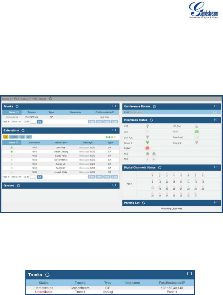
Firmware Version 1.0.0.5
UCM6510 IP PBX User Manual
Page 157 of 192
STATUS AND REPORTING
PBX STATUS
The UCM6510 monitors the status for Trunks, Extensions, Queues, Conference Rooms, Interfaces, Digital
Channels and Parking lot. It presents administrators the real time status in different sections under web
GUI->Status->PBX Status.
Figure 68: Status->PBX Status
TRUNKS
Users could see all the configured trunk status in this section.
Figure 69: Trunk Status

Firmware Version 1.0.0.5
UCM6510 IP PBX User Manual
Page 158 of 192
Table 57: Trunk Status
Status
Display trunk status.
Analog trunk/Digital trunk status:
Available
Busy
Unavailable
Unknown Error
SIP Peer trunk status:
Unreachable: The hostname cannot be reached.
Unmonitored: QUALIFY feature is not turned on to be monitored.
Reachable: The hostname can be reached.
SIP Register trunk status:
Registered
Unrecognized Trunk
Trunks
Display trunk name
Type
Display trunk Type:
Analog
E1/T1
SIP
IAX
Username
Display username for this trunk.
Port/Hostname/IP
Display Port for analog trunk, or Hostname/IP for VoIP (SIP/IAX) trunk.
Other operations are also available in trunk status section:
Click on "Trunks", the web page will redirect to trunk configuration page which can also be accessed via
web GUI->PBX->Basic/Call Routes->Analog Trunks.
Click on to refresh the trunk status.
Click on [ + ] to expand the status detail table.
Click on [ - ] to hide the status detail table.
EXTENSIONS
Users could see all the configured extension status in this section.
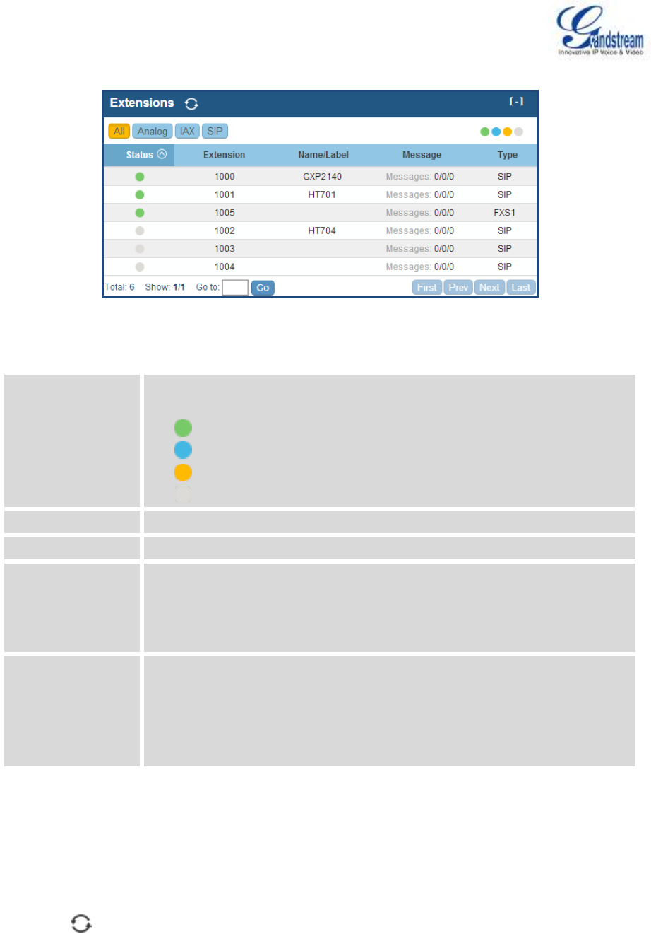
Firmware Version 1.0.0.5
UCM6510 IP PBX User Manual
Page 159 of 192
Figure 70: Extension Status
Table 58: Extension Status
Status
Display extension number (including feature code). The color indicator has
the following definitions.
Green: Free
Blue: Ringing
Yellow: In Use
Grey: Unavailable
Extension
Display the extension number.
Name/Label
Display name (callerID name) or label for the extension.
Message
Display message status for the extension.
Example: 2/4/1
Description: There are 2 urgent messages, 4 messages in total and 1
message that has been already read.
Type
Displays extension type.
SIP User
IAX User
Analog User (FXS)
Features
Other operations are also available in extension status section:
Click on "Extensions", the web page will redirect to extension configuration page which can also be
accessed via web GUI->PBX->Basic/Call Routes->Extensions.
Click on to refresh the extension status.
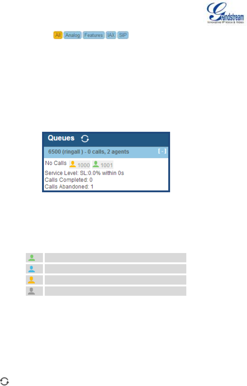
Firmware Version 1.0.0.5
UCM6510 IP PBX User Manual
Page 160 of 192
Click on one of the tabs to display the corresponding extensions
accordingly.
Click on [ + ] to expand the status detail table.
Click on [ - ] to hide the status detail table.
QUEUES
Users could see all the configured call queue status in this section. The following figure shows the call
queue 6500 being in used.
Figure 71: Queue Status
The current call status (caller ID, duration), agent status, service level, calls summary
(completed/abandoned) are shown for the call queue. The agent status is defined as below.
Table 59: Agent Status
The agent is available/idle.
The agent is ringing.
The agent is talking/busy.
The agent has been logged out.
On the UCM6510, Service Level is defined as the percentage of high-quality calls over all calls in the call
queue, where high-quality call means calls answered within 10 seconds.
Other operations are also available in queue status section:
Click on "Queues", the web page will redirect to call queue configuration page which can also be
accessed via web GUI->PBX->Call Features->Call Queue.
Click on to refresh the call queue status.
Click on [ + ] to expand the call queue detail.
Click on [ - ] to hide the call queue detail.
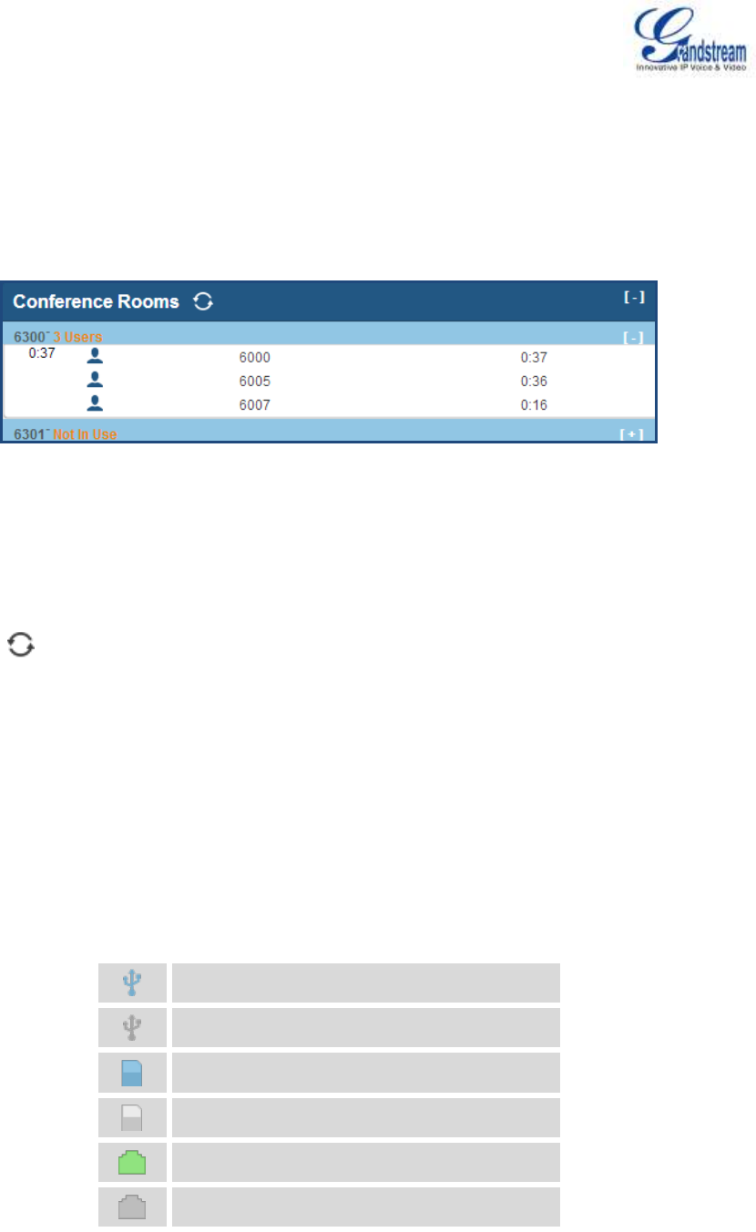
Firmware Version 1.0.0.5
UCM6510 IP PBX User Manual
Page 161 of 192
CONFERENCE ROOMS
Users could see all the conference room status in this section. It shows all the configured conference rooms,
current users, call duration for each user and conference call.
Figure 72: Conference Room Status
Other operations are also available in conference room status section:
Click on "Conference Rooms", the web page will redirect to conference room configuration page which
can also be accessed via web GUI->PBX->Call Features->Conference.
Click on to refresh the conference room status.
Click on [ + ] to expand the conference room details.
Click on [ - ] to hide the conference room details.
INTERFACES STATUS
This section displays interface connection status on the UCM6510 for USB, SD Card, LAN, WAN, LAN PoE,
Heartbeat, Power 1, Power 2, Digital, FXS and FXO ports.
Table 60: Interface Status Indicators
USB connected.
USB disconnected.
SD Card connected.
SD Card disconnected.
LAN/WAN/Heartbeat connected.
LAN/WAN/Heartbeat not configured.
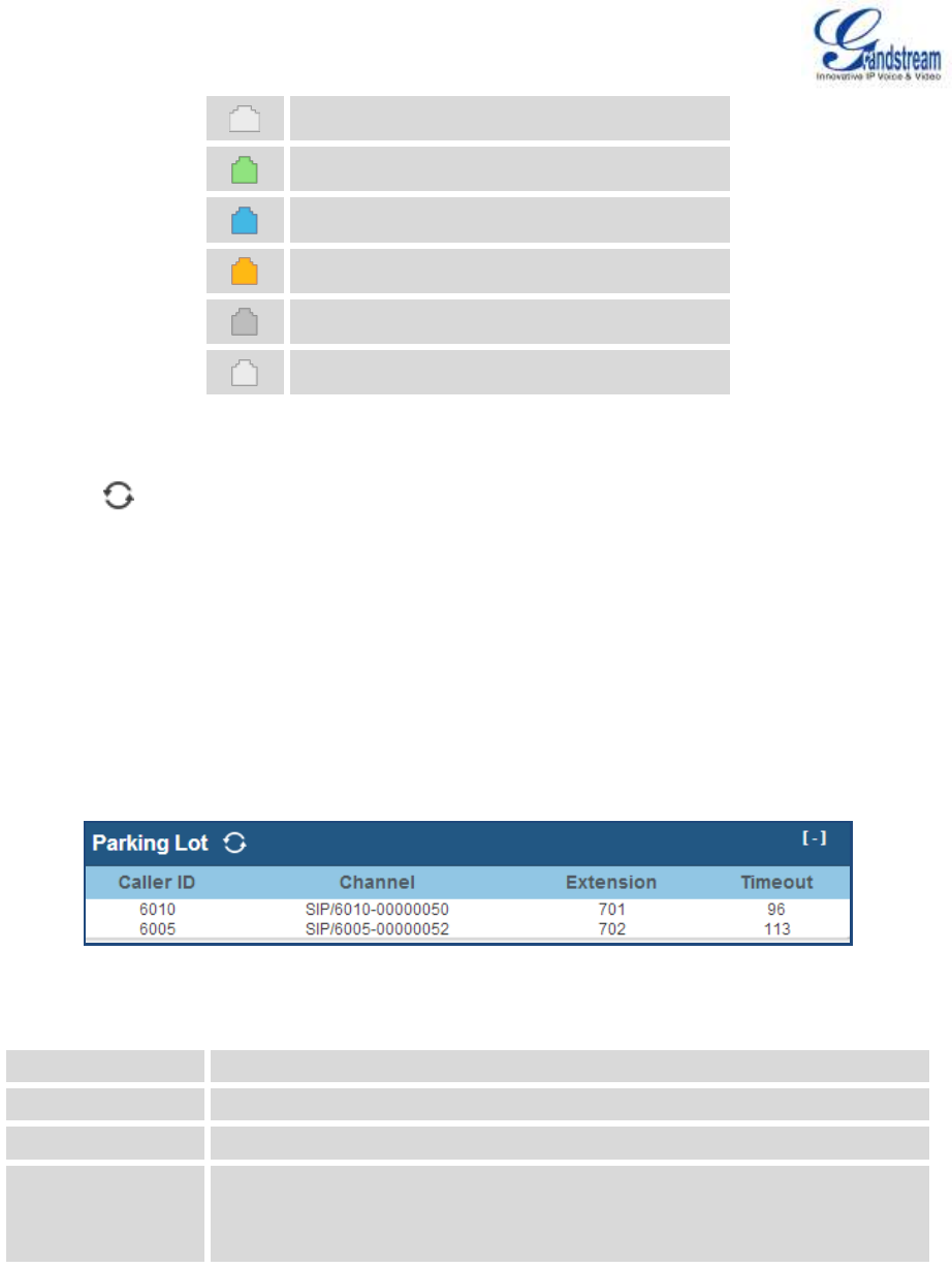
Firmware Version 1.0.0.5
UCM6510 IP PBX User Manual
Page 162 of 192
LAN/WAN/Heartbeat disconnected.
FXS/FXO/Digital connected.
FXS/FXO/Digital waiting.
FXS/FXO/Digital busy.
FXS/FXO/Digital not configured.
FXS/FXO/Digital disconnected.
Other operations are also available in interface status section:
Click on to refresh the interface status.
Click on [ + ] to expand the interface details.
Click on [ - ] to hide the interface details.
PARKING LOT
The UCM6510 supports call park using feature code. When there is call being parked, this section will
display the parking lot status.
Figure 73: Parking Lot Status
Table 61: Parking Lot Status
Caller ID
Display the caller ID who parks the call.
Channel
Display channel for the call park.
Extension
Display the parking lot number where the call is parked/retrieved.
Timeout
Display timeout (in seconds) for the parked call. The status page will
dynamically update this timer from 120 seconds (default) to 0. When the
timer reaches 0, the caller who parks the call will be called back.
Other operations are also available in parking lot status section:

Firmware Version 1.0.0.5
UCM6510 IP PBX User Manual
Page 163 of 192
Click on "Parking Lot", the web page will redirect to feature codes page which can also be accessed via
web GUI->PBX->Internal Options->Feature Codes.
Click on to refresh the parking lot status.
Click on [ + ] to expand the parking lot details.
Click on [ - ] to hide the parking details.
SYSTEM STATUS
The UCM6510 system status can be accessed via web GUI->Status->System Status, which displays the
following system information.
General
Network
Storage Usage
Resource Usage
GENERAL
Under web GUI->Status->System Status->General, users could check the hardware and software
information for the UCM6510. Please see details in the following table.
Table 62: System Status->General
Status ->System Status -> General
Model
Product model.
Part Number
Product part number.
System Time
Current system time. The current system time is also available on the upper right of
each web page.
Up Time
System up time since the last reboot.
Idle Time
System idle time since the last reboot.
Boot
Boot version.
Core
Core version.
Base
Base version.
Program
Program version. This is the main software release version.
Recovery
Recovery version.

Firmware Version 1.0.0.5
UCM6510 IP PBX User Manual
Page 164 of 192
NETWORK
Under web GUI->Status->System Status->Network, users could check the network information for the
UCM6510. Please see details in the following table.
Table 63: System Status->Network
Status -> System Status -> Network
MAC Address
Global unique ID of device, in HEX format. The MAC address can be found on the
label coming with original box and on the label located on the bottom of the device.
IP Address
IP address.
Gateway
Default gateway address.
Subnet Mask
Subnet mask address.
DNS Server
DNS Server address.
STORAGE USAGE
Users could access the storage usage information from web GUI->Status->System Status->Storage
Usage. It shows the available and used space for the following partitions.
Configuration partition
This partition contains PBX system configuration files and service configuration files.
Data partition
Voicemail, recording files, IVR file, music on hold files and etc.
USB disk
USB disk will display if connected.
SD Card
SD Card will display if connected.
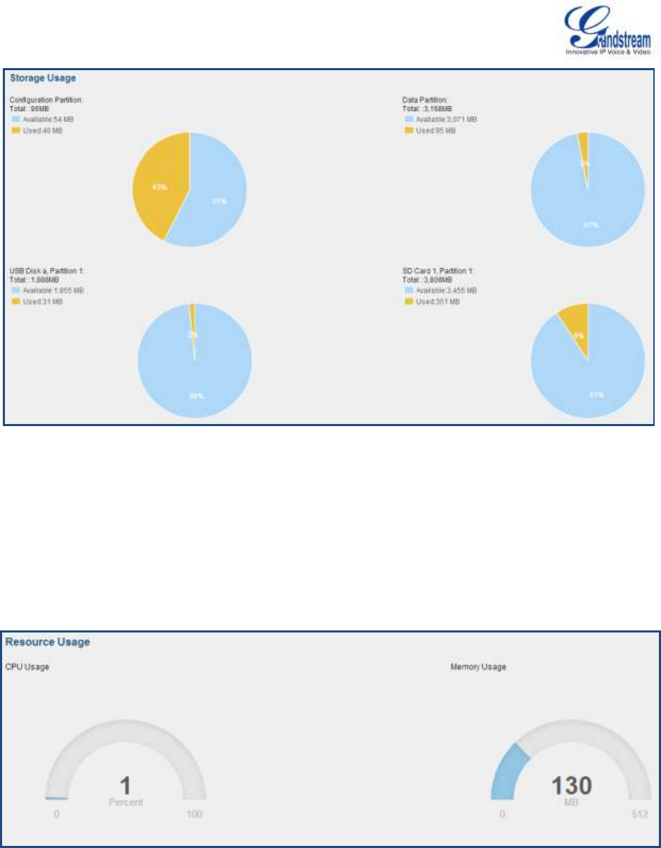
Firmware Version 1.0.0.5
UCM6510 IP PBX User Manual
Page 165 of 192
Figure 74: System Status->Storage Usage
RESOURCE USAGE
When configuring and managing the UCM6510, users could access resource usage information to estimate
the current usage and allocate the resources accordingly. Under web GUI->Status->System
Status->Resource Usage, the current CPU usage and Memory usage are shown in the pie chart.
Figure 75: System Status->Resource Usage
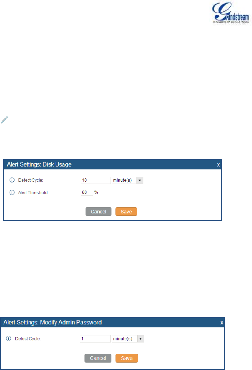
Firmware Version 1.0.0.5
UCM6510 IP PBX User Manual
Page 166 of 192
SYSTEM EVENTS
The UCM6510 can monitor important system events, log the alerts and send Email notifications to the
system administrator.
ALERT EVENTS LIST
The system alert events list can be found under web GUI->Status->System Events->Alert Events List.
Click on to configure the parameters for each event.
1. Disk Usage
Figure 76: System Events->Alert Events Lists: Disk Usage
Detect Cycle: The UCM6510 will perform the internal disk usage detection based on this cycle.
Users can enter the number and then select second(s)/minute(s)/hour(s)/day(s) to configure the
cycle.
Alert Threshold: If the detected value exceeds the threshold (in percentage), the UCM6510
system will send the alert.
2. Modify Admin Password
Figure 77: System Events->Alert Events Lists: Modify Admin Password
Detect Cycle: The UCM6510 will initiate the admin password check based on this cycle. Users can
enter the number and then select second(s)/minute(s)/hour(s)/day(s) to configure the cycle.
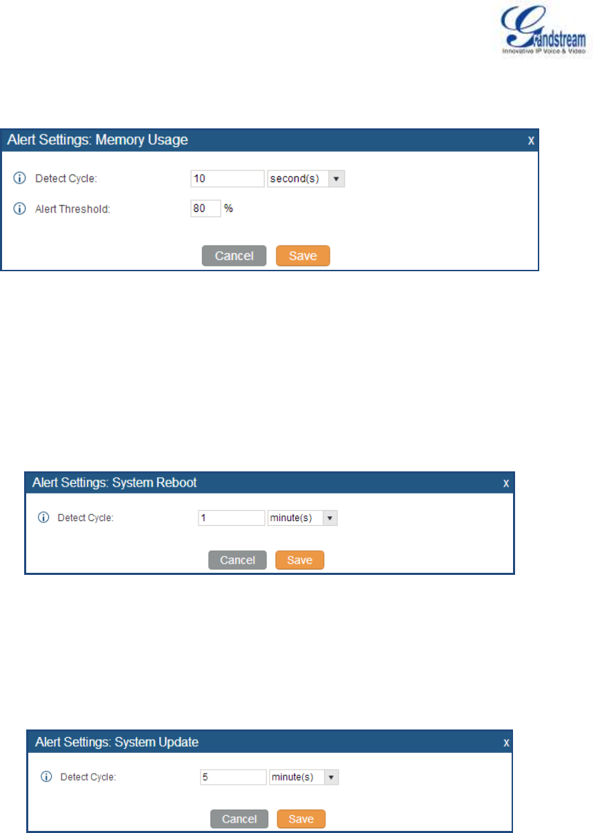
Firmware Version 1.0.0.5
UCM6510 IP PBX User Manual
Page 167 of 192
3. Memory Usage
Figure 78: System Events->Alert Events Lists: Memory Usage
Detect Cycle: The UCM6510 will perform the memory usage detection based on this cycle. Users
can enter the number and then select second(s)/minute(s)/hour(s)/day(s) to configure the cycle.
Alert Threshold: If the detected value exceeds the threshold (in percentage), the UCM6510
system will send the alert.
4. System Reboot
Figure 79: System Events->Alert Events Lists: System Reboot
Detect Cycle: The UCM6510 will check the system reboot based on this cycle. Users can enter the
number and then select second(s)/minute(s)/hour(s)/day(s) to configure the cycle.
5. System Update
Figure 80: System Events->Alert Events Lists: System Update
Detect Cycle: The UCM6510 will check the system update based on this cycle. Users can enter
the number and then select second(s)/minute(s)/hour(s)/day(s) to configure the cycle.
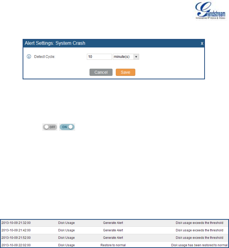
Firmware Version 1.0.0.5
UCM6510 IP PBX User Manual
Page 168 of 192
6. System Crash
Figure 81: System Events->Alert Events Lists: System Crash
Detect Cycle: The UCM will detect the event at each cycle based on the specified time. Users can
enter the number and then select second(s)/minute(s)/hour(s)/day(s) to configure the cycle.
Click on the switch to turn on/off the alert and Email notification for the event. Users could
also select the checkbox for each event and then click on button "Alert On", "Alert Off", "Email Notification
On", "Email Notification Off" to control the alert and Email notification configuration.
ALERT LOG
Under web GUI->Status->System Events->Alert Log, system messages are listed when the alert is
triggered for the configured system events. The following picture shows disk usage alert log. We can tell the
detect cycle for the disk usage is 10 minutes and the disk usage is restored to normal after the administrator
cleans up the disk storage below the threshold.
Figure 82: System Events->Alert Log
ALERT CONTACT
Users could add administrator's Email address under web GUI->Status->System Events->Alert Contact
to send the alert notification to. Up to 10 Email addresses can be added.
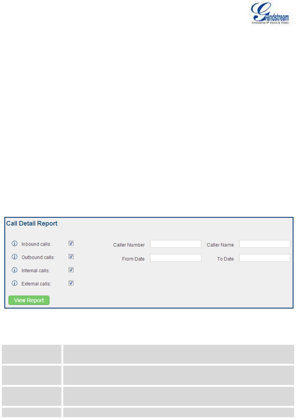
Firmware Version 1.0.0.5
UCM6510 IP PBX User Manual
Page 169 of 192
CDR
A Call Detail Record (CDR) is a data record produced by telephone exchange activities or other
telecommunications equipment documenting the details of a phone call that passed through the PBX. The
CDR is composed of the following data fields on the UCM6510.
Start Time. Format: 2013-03-27 16:47:03.
Call From. Format: "John Doe"<6012>.
Call To. Format: 6005.
Call Time. Format: 0:00:10.
Talk Time. Format: 0:00:10
Status. Format: NO ANSWER, BUSY, ANSWERED, or FAILED.
Options. Voice record playing/downloading/deleting.
Users could filter the call report by specifying the date range and criteria, depending on how the users
would like to include the logs to the report. Then click on "View Report" button to display the generated
report.
Figure 83: CDR Filter
Table 64: CDR Filter Criteria
Inbound calls
Inbound calls are calls originated from a non-internal source (like a VoIP trunk) and
sent to an internal extension.
Outbound calls
Outbound calls are calls sent to a non-internal source (like a VoIP trunk) from an
internal extension.
Internal calls
Internal calls are calls from one internal extension to another extension, which are
not sent over a trunk.
External calls
External calls are calls sent from one trunk to another trunk, which are not sent to
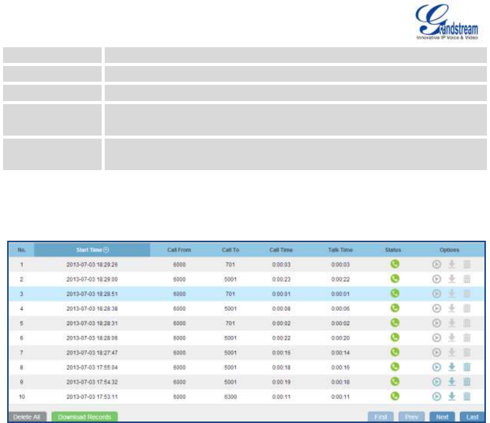
Firmware Version 1.0.0.5
UCM6510 IP PBX User Manual
Page 170 of 192
any internal extension.
Caller Number
Enter the caller number to be filtered in the CDR report.
Caller Name
Enter the caller name to be filtered in the CDR report.
From Date
Specify "From" date and time to be filtered for the CDR report. Click on the field and
the calendar will show for users to select the exact date and time.
To Date
Specify "To" date and time to be filtered for the CDR report. Click on the field and
the calendar will show for users to select the exact date and time.
The call report will display as the following figure shows.
Figure 84: Call Report
Users could perform the following operations on the call report.
Sort
Click on the header of the column to sort by this category. For example, clicking on "Start Time" will
sort the report according to start time. Clicking on "Start Time" again will reverse the order.
Download Records
On the bottom of the page, click on "Download Records" button to export the report in .csv format.
Delete All
On the bottom of the page, click on "Delete All" button to remove all the call report information.
Play/Download/Delete Recording File (per entry)
If the entry has audio recording file for the call, the three icons on the most right column will be
activated for users to select. In the following picture, the second entry has audio recording file for the
call.
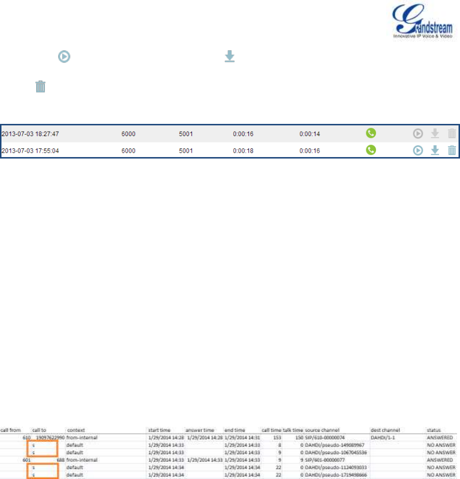
Firmware Version 1.0.0.5
UCM6510 IP PBX User Manual
Page 171 of 192
Click on to play the recording file; click on to download the recording file in .wav format; click
on to delete the recording file (the call record entry will not be deleted).
Figure 85: Call Report Entry With Audio Recording File
DOWNLOADED CDR FILE
The downloaded CDR (.csv file) has different format from the web UI CDR. Here are some descriptions.
Call From, Call To
"Call From": the caller ID.
"Call To": the callee ID.
If "Call From" shows empty, "Call To" shows "s" (see highlight part in the picture below) and the "Source
Channel" contains "DAHDI", this means the call is from FXO/PSTN line. For FXO/PSTN line, we only know
there is an incoming request when there is incoming call but we don't know the number being called. So
we are using "s" to match it where "s" means "start".
Figure 86: Downloaded CDR File Sample - Call To Shows "s"
Context
There are different context values that might show up in the downloaded CDR file. The actual value can
vary case by case. Here are some sample values and their descriptions.
from-internal: internal extension makes outbound calls.
ext-did-XXXXX: inbound calls. It starts with "ext-did", and "XXXXX" content varies case by case, which
also relate to the order when the trunk is created.
ext-local: internal calls between local extensions.
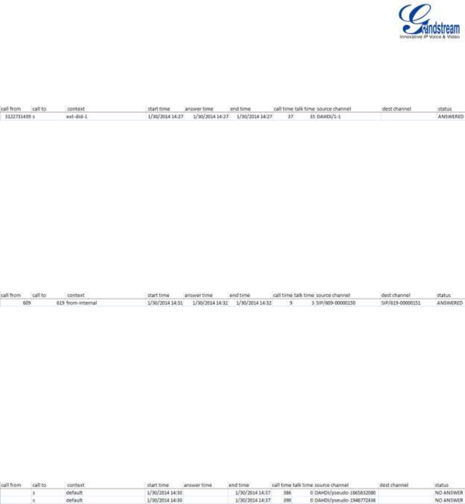
Firmware Version 1.0.0.5
UCM6510 IP PBX User Manual
Page 172 of 192
Source Channel, Dest Channel
Sample 1:
Figure 87: Downloaded CDR File Sample - Source Channel and Dest Channel 1
DAHDI means it is an analog call, FXO or FXS.
For UCM6510, DAHDI/(1-2) are FXO ports, and DAHDI(3-4) are FXS ports.
For UCM6510, DAHDI/(1-4) are FXO ports, and DAHDI(5-6) are FXS ports.
For UCM6510, DAHDI/(1-8) are FXO ports, and DAHDI(9-10) are FXS ports.
For UCM6510, DAHDI/(1-16) are FXO ports, and DAHDI/(17-18) are FXS ports.
Sample 2:
Figure 88: Downloaded CDR File Sample - Source Channel and Dest Channel 2
"SIP" means it's a SIP call. There are three possible format:
(a) SIP/NUM-XXXXXX, where NUM is the local SIP extension number. The last XXXXX is a random string
and can be ignored.
(c) SIP/trunk_X/NUM, where trunk_X is the internal trunk name, and NUM is the number to dial out
through the trunk.
(c) SIP/trunk_X-XXXXXX, where trunk_X is the internal trunk name and it is an inbound call from this trunk.
The last XXXXX is a random string and can be ignored.
Sample 3:
Figure 89: Downloaded CDR File Sample - Source Channel and Dest Channel 3
This is a very special channel name. If it shows up, most likely it means a conference call.
There are some other possible values, but these values are almost the application name which are used
by the dialplan.
IAX2/NUM-XXXXXXX: it means this is an IAX call.
Local/@from-internal-XXXXX: it is used internally to do some special feature procedure. We can simply
ignore it.
Hangup: the call is hung up from the dialplan. This indicates there are some errors or it has run into
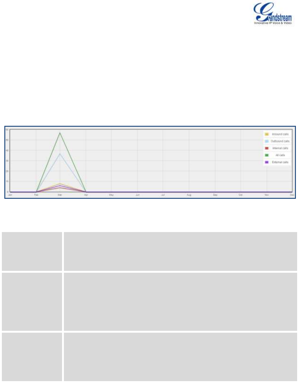
Firmware Version 1.0.0.5
UCM6510 IP PBX User Manual
Page 173 of 192
abnormal cases.
Playback: play some prompts to you, such as 183 response or run into an IVR.
ReadExten: collect numbers from user. It may occur when you input PIN codes or run into DISA
STATISTICS
CDR Statistics is an additional feature on the UCM6510 which provides users a visual overview of the call
report across the time frame. Users can filter with different criteria to generate the statistics chart.
Figure 90: CDR Statistics
Table 65: CDR Statistics Filter Criteria
Trunk Type
Select one of the following trunk type.
All
SIP Calls
PSTN Calls
Call Type
Select one or more in the following checkboxes.
Inbound calls
Outbound calls
Internal calls
External calls
All calls
Time Range
By month (of the selected year).
By week (of the selected year).
By day (of the specified month for the year).
By hour (of the specified date).
By range. For example, 2013-01 To 2013-03.

Firmware Version 1.0.0.5
UCM6510 IP PBX User Manual
Page 174 of 192
RECORDING FILES
The recording files recorded by "Auto Record" per extension/per trunk, or via feature code "Audio Mix
Record" are listed here. Users could click on to play the recording file; click on to download the
recording file in .wav format; or click on to delete the recording file.
To sort the recording file, click on the title "Caller", "Callee" or "Call Time" for the corresponding column.
Click on the title again can switch the sorting mode between ascending order or descending order.
CDR API CONFIGURATION FILES
The UCM6510 supports third party billing interface API for external billing software to access CDR on the
PBX. The API uses HTTPS to request the CDR data matching given parameters as configured on the third
party application. Before accessing the API, the administrators need enable API and configure the
access/authentication information on the UCM6510 first.
Table 66: CDR API Configuration Files
Enable
Enable/Disable CDR API. The default setting is disabled.
TLS Bind Address
Configure the IP address for TLS server to bind to. "0.0.0.0" means binding to all
interfaces. The port number is optional and the default port number is 8443. The IP
address must match the common name (host name) in the certificate so that the
TLS socket won't bind to multiple IP addresses. The default setting is 0.0.0.0:8443.
TLS Private Key
Upload TLS private key. The size of the key file must be under 2MB. This file will be
renamed as 'private.pem' automatically.
TLS Cert
Upload TLS cert. The size of the certificate must be under 2MB. This is the
certificate file (*.pem format only) for TLS connection. This file will be renamed as
"certificate.pem" automatically. It contains private key for the client and signed
certificate for the server.
TLS Authentication
Name
Configure the user name for TLS authentication. If not configured, authentication
will be skipped.
TLS Authentication
Password
Configure the password for TLS authentication. This is optional.
Permitted
Specify a list of IP addresses permitted by CDR API. This creates an AIP-specific
access control list. Multiple entries are allowed.
For example, "192.168.40.3/255.255.255.255" denies access from all IP addresses
except 192.168.40.3.

Firmware Version 1.0.0.5
UCM6510 IP PBX User Manual
Page 175 of 192
The format of the HTTPS request for the CDR API is as below.
https://[UCM IP]:[Port]/cdrapi?[option1]=[value]&[option2]=[value]&...
By default, the port number for the API is 8443.
The options included in the request URI control the record matching and output format. For CDR matching
parameters, all non-empty parameters must have a match to return a record. Parameters can appear in
the URI in any order. Multiple values given for caller or callee will be concatenated. The following table
shows the parameter list used in the CDR API.
Table 67: CDR API URI Parameters
Field
Value
Details
format
csv, xml, json
Define the format for output of matching CDR rows.
Default is csv (comma separated values).
numRecords
Number: 0-1000
Number of records to return. Default is 1000, which is
also the maximum allowed value.
offset
Number
Number of matching records to skip. This will be
combined with numRecords to receive all matches
over multiple responses. Default is 0.
caller
Comma separated extensions,
ranges of extensions, or regular
expressions.
Example:
caller=5300,5302-5304,_4@
-OR-
caller=5300&caller=5302-5304&
caller=_4@
(Matches extensions 5300, 5302,
5303, 5304, and any extension
containing 4 as the second
digit/character).
Filters based on src (caller) or dst (callee) value,
matching any extension contained in the parameter
input string.
Patterns containing one or more wildcards ('@' or '_')
will match as a regular expression, and treat '-' as a
literal hyphen rather than a range signifier. The '@'
wildcard matches any number of characters (including
zero), while '_' matches any single character.
Otherwise, patterns containing a single hyphen will be
matching a range of numerical extensions, with
non-numerical characters ignored, while patterns
containing multiple hyphens will be ignored. (The
pattern "0-0" will match all non-numerical and empty
strings).
callee

Firmware Version 1.0.0.5
UCM6510 IP PBX User Manual
Page 176 of 192
startTime
Date and/or time of day in any of
the following formats:
YYYY-MM-DDTHH:MM
YYYY-MM-DDTHH:MM:SS
YYYY-MM-DDTHH:MM:SS.SSS
(literal 'T' character separator in
above three formats)
HH:MM
HH:MM:SS
HH:MM:SS.SSS
now
DDDDDDDDDD
Filters based on the start (call start time) value. Calls
which start within this period (inclusive of boundaries)
will match, regardless of the call answer or end time.
An empty value for either field will be interpreted as
range with no minimum or maximum respectively.
Strings without a date have a default value of
2000-01-01. Strings without a time of day have a
default value of of 00:00 UTC, while strings with a time
of day specified may also optionally specify a time
zone offset - replace '+' in time zone offset with '%2B'
(see http://www.w3.org/TR/NOTE-datetime).
endTime
minDur
Number (duration in seconds)
Filters based on the billsec value, the duration between
call answer and call end.
maxDur
Example Queries:
The following illustrates the format of queries to accomplish certain requests. In most cases, multiple
different queries will accomplish the same goal, and these examples are not intended to be exhaustive, but
rather to bring attention to particular features of the CDR API connector.
Query 1: Request all records of calls placed on extension 5300 which last between 8 and 60 seconds
(inclusive), with results in CSV format.
https://192.168.254.200:8088/cdrapi?format=CSV&caller=5300&minDur=8&maxDur=60
-OR-
https://192.168.254.200:8088/cdrapi?caller=5300&minDur=8&maxDur=60

Firmware Version 1.0.0.5
UCM6510 IP PBX User Manual
Page 177 of 192
Query 2: Request all records of calls placed on extension 5300 or in the range 6300-6399 to extensions
starting with 5, with results in XML format.
https://192.168.254.200:8088/cdrapi?format=XML&caller=5300,6300-6399&callee=5@
-OR-
https://192.168.254.200:8088/cdrapi?cdrapi?format=XML&caller=5300&caller=6300-6399&callee=5@
Query 3: Request all records of calls placed on extensions containing substring "53" prior to January 23,
2013 00:00:00 UTC to extensions 5300-5309, with results in CSV format.
https://192.168.254.200:8088/cdrapi?caller=@53@&callee=5300-5309&endTime=2013-01-23
-OR-
https://192.168.254.200:8088/cdrapi?caller=@53@&callee=530_&endTime=2013-01-23T00:00:00
Query 4: Request all records of calls placed by an Anonymous caller during July 2013 Central Standard
Time to extensions starting with 2 or 34 or ending with 5, with results in CSV format.
https://192.168.254.200:8088/cdrapi?caller=Anonymous&callee=2@,34@,@5&startTime=2013-07-01T00:00:00-
06:00&endTime=2013-07-31T23:59:59-06:00
Query 5: Request all records during July 2013 Central Standard Time, 200 at a time, with results in CSV
format.
https://192.168.254.200:8088/cdrapi?startTime=2013-07-01T00:00:00-06:00&endTime=2013-07-31T23:59:59-06:
00&numRecords=200&offset=0
-THEN-
https://192.168.254.200:8088/cdrapi?sstartTime=2013-07-01T00:00:00-06:00&endTime=2013-07-31T23:59:59-0
6:00&numRecords=200&offset=200
-THEN-
https://192.168.254.200:8088/cdrapi?startTime=2013-07-01T00:00:00-06:00&endTime=2013-07-31T23:59:59-06:
00&numRecords=200&offset=400

Firmware Version 1.0.0.5
UCM6510 IP PBX User Manual
Page 178 of 192
Note:
Disallowed characters in the caller, callee, startTime, or endTime strings, and non-digit characters
in the values of numRecords, offset, minDur, or maxDur, will result in no records returned - the
appropriate container/header for the output format will be the only output. If the format parameter
is in error, the CSV header will be used. Error messages will appear in the Asterisk log (along with
errors stemming from failed database connections, etc.).
Other errors which return no records include:
- Multiple hyphens in an extension range (e.g. caller=5300-5301-,6300)
- Empty parameter value (e.g. caller=)
- Extension values starting with comma, or with consecutive commas (e.g. caller=5300,,5303)
- Unknown parameters (e.g. caler=5300) or URI ending with '&'
- Except for caller and callee, multiple instances of the same parameter within the URI (e.g.
minDur=5&minDur=10)
Example Output:
The following are examples of each of the output formats for the same data set.
CSV:
AcctId,accountcode,src,dst,dcontext,clid,channel,dstchannel,lastapp,lastdata,start,answer,end,duration
,billsec,disposition,amaflags,uniqueid,userfield,channel_ext,dstchannel_ext,service
62,,5300,5301,from-internal,"pn01"
<5300>,SIP/5300-00000000,SIP/5301-00000001,Dial,SIP/5301,60,,2013-12-03 11:46:40,2013-12-03
11:46:43,2013-12-03 11:46:49,9,6,ANSWERED,DOCUMENTATION,1386092800.0,EXT,5300,5301,s
63,,5300,5301,from-internal,"pn01"
<5300>,SIP/5300-00000000,SIP/5301-00000001,Dial,SIP/5301,60,,2013-12-03 14:01:41,2013-12-03
14:01:43,2013-12-03 14:01:46,5,3,ANSWERED,DOCUMENTATION,1386100901.0,EXT,5300,5301,s
64,,5300,5301,from-internal,"pn01"
<5300>,SIP/5300-00000002,SIP/5301-00000003,Dial,SIP/5301,60,,2013-12-03 14:02:23,2013-12-03
14:02:27,2013-12-03 14:02:31,8,4,ANSWERED,DOCUMENTATION,1386100943.2,EXT,5300,5301,s

Firmware Version 1.0.0.5
UCM6510 IP PBX User Manual
Page 179 of 192
XML:
JSON:
<root>
<cdr><AcctId>62</AcctId><accountcode></accountcode><src>5300</src><dst>5301</dst><dcontext
>from-internal</dcontext><clid>"pn01"
<5300></clid><channel>SIP/5300-00000000</channel><dstchannel>SIP/5301-00000001</dstcha
nnel><lastapp>Dial</lastapp><lastdata>SIP/5301,60,</lastdata><start>2013-12-03
11:46:40</start><answer>2013-12-03 11:46:43</answer><end>2013-12-03
11:46:49</end><duration>9</duration><billsec>6</billsec><disposition>ANSWERED</disposition><a
maflags>DOCUMENTATION</amaflags><uniqueid>1386092800.0</uniqueid><userfield>EXT</userfi
eld><channel_ext>5300</channel_ext><dstchannel_ext>5301</dstchannel_ext><service>s</service>
</cdr>
<cdr><AcctId>63</AcctId><accountcode></accountcode><src>5300</src><dst>5301</dst><dcontext
>from-internal</dcontext><clid>"pn01"
<5300></clid><channel>SIP/5300-00000000</channel><dstchannel>SIP/5301-00000001</dstcha
nnel><lastapp>Dial</lastapp><lastdata>SIP/5301,60,</lastdata><start>2013-12-03
14:01:41</start><answer>2013-12-03 14:01:43</answer><end>2013-12-03
14:01:46</end><duration>5</duration><billsec>3</billsec><disposition>ANSWERED</disposition><a
maflags>DOCUMENTATION</amaflags><uniqueid>1386100901.0</uniqueid><userfield>EXT</userfi
eld><channel_ext>5300</channel_ext><dstchannel_ext>5301</dstchannel_ext><service>s</service>
</cdr>
<cdr><AcctId>64</AcctId><accountcode></accountcode><src>5300</src><dst>5301</dst><dcontext
>from-internal</dcontext><clid>"pn01"
<5300></clid><channel>SIP/5300-00000002</channel><dstchannel>SIP/5301-00000003</dstcha
nnel><lastapp>Dial</lastapp><lastdata>SIP/5301,60,</lastdata><start>2013-12-03
14:02:23</start><answer>2013-12-03 14:02:27</answer><end>2013-12-03
14:02:31</end><duration>8</duration><billsec>4</billsec><disposition>ANSWERED</disposition><a
maflags>DOCUMENTATION</amaflags><uniqueid>1386100943.2</uniqueid><userfield>EXT</userfi
eld><channel_ext>5300</channel_ext><dstchannel_ext>5301</dstchannel_ext><service>s</service>
</cdr>
</root>
{
"cdr":
[
{ "AcctId": "62", "accountcode": "", "src": "5300", "dst": "5301", "dcontext": "from-internal", "clid":
"\"pn01\" <5300>", "channel": "SIP/5300-00000000", "dstchannel": "SIP/5301-00000001", "lastapp":
"Dial", "lastdata": "SIP/5301,60,", "start": "2013-12-03 11:46:40", "answer": "2013-12-03 11:46:43",
"end": "2013-12-03 11:46:49", "duration": "9", "billsec": "6", "disposition": "ANSWERED", "amaflags":
"DOCUMENTATION", "uniqueid": "1386092800.0", "userfield": "EXT", "channel_ext": "5300",
"dstchannel_ext": "5301", "service": "s" },
{ "AcctId": "63", "accountcode": "", "src": "5300", "dst": "5301", "dcontext": "from-internal", "clid":
"\"pn01\" <5300>", "channel": "SIP/5300-00000000", "dstchannel": "SIP/5301-00000001", "lastapp":
"Dial", "lastdata": "SIP/5301,60,", "start": "2013-12-03 14:01:41", "answer": "2013-12-03 14:01:43",
"end": "2013-12-03 14:01:46", "duration": "5", "billsec": "3", "disposition": "ANSWERED", "amaflags":
"DOCUMENTATION", "uniqueid": "1386100901.0", "userfield": "EXT", "channel_ext": "5300",
"dstchannel_ext": "5301", "service": "s" },
{ "AcctId": "64", "accountcode": "", "src": "5300", "dst": "5301", "dcontext": "from-internal", "clid":
"\"pn01\" <5300>", "channel": "SIP/5300-00000002", "dstchannel": "SIP/5301-00000003", "lastapp":
"Dial", "lastdata": "SIP/5301,60,", "start": "2013-12-03 14:02:23", "answer": "2013-12-03 14:02:27",
"end": "2013-12-03 14:02:31", "duration": "8", "billsec": "4", "disposition": "ANSWERED", "amaflags":
"DOCUMENTATION", "uniqueid": "1386100943.2", "userfield": "EXT", "channel_ext": "5300",
"dstchannel_ext": "5301", "service": "s" }
]
}
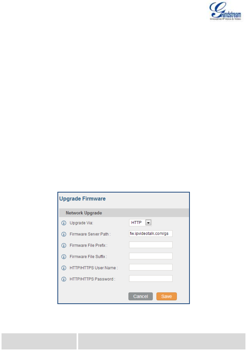
Firmware Version 1.0.0.5
UCM6510 IP PBX User Manual
Page 180 of 192
UPGRADING AND MAINTENANCE
UPGRADING
The UCM6510 can be upgraded to a new firmware version remotely or locally. This section describes how
to upgrade your UCM6510 via network or local upload.
UPGRADING VIA NETWORK
The UCM6510 can be upgraded via TFTP/HTTP/HTTPS by configuring the URL/IP Address for the
TFTP/HTTP/HTTPS server and selecting a download method. Configure a valid URL for TFTP, HTTP or
HTTPS; the server name can be FQDN or IP address.
Examples of valid URLs:
firmware.grandstream.com
The upgrading configuration can be accessed via web GUI->Maintenance->Upgrade.
Figure 91: Network Upgrade
Table 68: Network Upgrade Configuration
Upgrade Via
Allow users to choose the firmware upgrade method: TFTP, HTTP or
HTTPS.
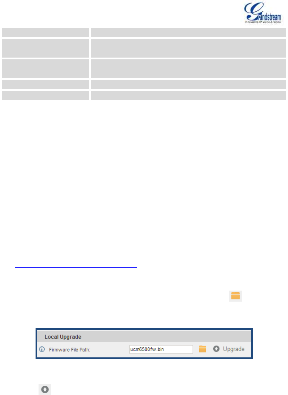
Firmware Version 1.0.0.5
UCM6510 IP PBX User Manual
Page 181 of 192
Firmware Server Path
Define the server path for the firmware server.
Firmware File Prefix
If configured, only the firmware with the matching encrypted prefix will
be downloaded and flashed into the UCM6510.
Firmware File Suffix
If configured, only the firmware with the matching encrypted postfix will
be downloaded and flashed into the UCM6510.
HTTP/HTTPS User Name
The user name for the HTTP/HTTPS server.
HTTP/HTTPS Password
The password for the HTTP/HTTPS server.
Please follow the steps below to upgrade the firmware remotely.
Enter the firmware server path under web GUI->Maintenance->Upgrade.
Click on "Save". Then reboot the device to start the upgrading process.
Please be patient during the upgrading process. Once done, a reboot message will be displayed in the
LCD.
Manually reboot the UCM6510 when it's appropriate to avoid immediate service interruption. After it
boots up, log in the web GUI to check the firmware version.
UPGRADING VIA LOCAL UPLOAD
If there is no HTTP/TFTP server, users could also upload the firmware to the UCM6510 directly via web
GUI. Please follow the steps below to upload firmware locally.
Download the latest UCM6510 firmware file from the following link and save it in your PC.
http://www.grandstream.com/support/firmware
Log in the web GUI as administrator in the PC.
Go to web GUI->Maintenance->Upgrade, upload the firmware file by clicking on and select the
firmware file from your PC. The default firmware file name is ucm6510fw.bin
Figure 92: Local Upgrade
Click on to start upgrading.
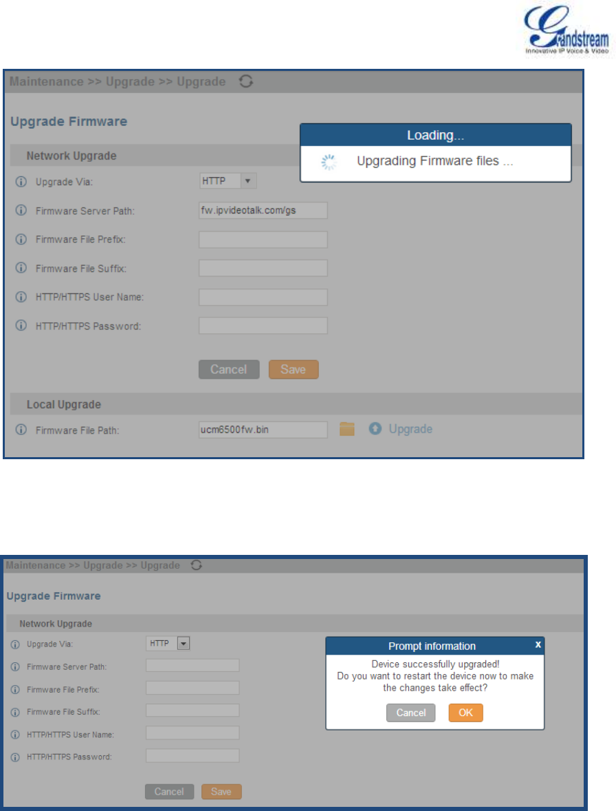
Firmware Version 1.0.0.5
UCM6510 IP PBX User Manual
Page 182 of 192
Figure 93: Upgrading Firmware Files
Wait until the upgrading process is successful and a window will be popped up in the web GUI.
Figure 94: Reboot UCM6510
Click on "OK" to reboot the UCM6510 and check the firmware version after it boots up.
Firmware Version 1.0.0.5
UCM6510 IP PBX User Manual
Page 183 of 192
Note:
Please do not interrupt or power cycle the UCM6510 during upgrading process.
NO LOCAL FIRMWARE SERVERS
For users that would like to use remote upgrading without a local TFTP server, Grandstream offers a
NAT-friendly HTTP server. This enables users to download the latest software upgrades for their devices
via this server. Please refer to the webpage:
http://www.grandstream.com/support/firmware.
Alternatively, users can download a free TFTP or HTTP server and conduct a local firmware upgrade. A
free windows version TFTP server is available for download from :
http://www.solarwinds.com/products/freetools/free_tftp_server.aspx
http://tftpd32.jounin.net
Instructions for local firmware upgrade via TFTP:
1. Unzip the firmware files and put all of them in the root directory of the TFTP server;
2. Connect the PC running the TFTP server and the UCM6510 to the same LAN segment;
3. Launch the TFTP server and go to the File menu->Configure->Security to change the TFTP server's
default setting from "Receive Only" to "Transmit Only" for the firmware upgrade;
4. Start the TFTP server and configure the TFTP server in the UCM6510 web configuration interface;
5. Configure the Firmware Server Path to the IP address of the PC;
6. Update the changes and reboot the UCM6510.
End users can also choose to download a free HTTP server from http://httpd.apache.org/ or use
Microsoft IIS web server.
BACKUP
The UCM6510 configuration can be backed up locally or via network. The backup file will be used to
restore the configuration on UCM6510 when necessary.
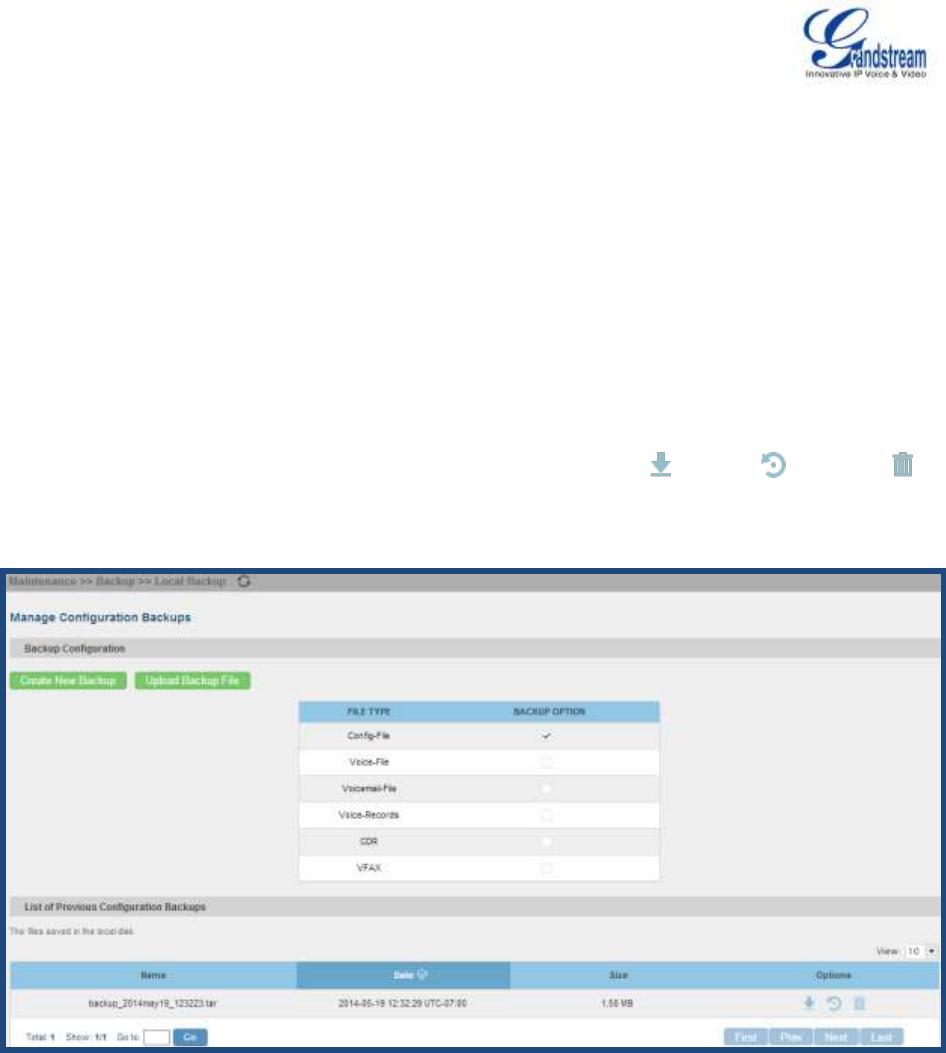
Firmware Version 1.0.0.5
UCM6510 IP PBX User Manual
Page 184 of 192
LOCAL BACKUP
Users could backup the UCM6510 configurations for restore purpose under web
GUI->Maintenance->Backup->Local Backup. Before creating new backup file, select the backup option
first.
If the Config-File is selected only, the backup file will be saved in the flash of the UCM6510.
If Voice-File, Voicemail-File, Voice-Records, CDR or VFAX is selected, external storage devices (USB
Flash drive or SD Card) will be required because the backup file might be too large.
Click on "Create New Backup" button to start backup. Once the backup is done, the list of the backups will
be displayed with date and time in the web page. Users can download , restore , or delete it
from the UCM6510 internal storage or the external device.
Figure 95: Local Backup
DATA SYNC
Besides local backup, users could backup the voice records/voice mails/CDR/FAX in a daily basis to a
remote server via SFTP protocol automatically under web GUI->Maintenance->Backup->Data Sync.
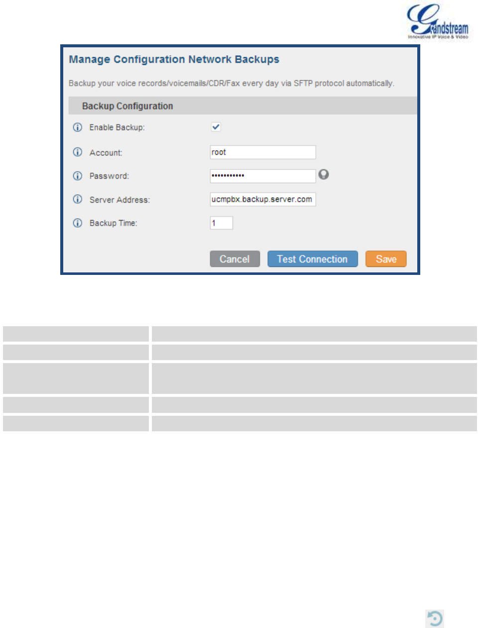
Firmware Version 1.0.0.5
UCM6510 IP PBX User Manual
Page 185 of 192
Figure 96: Data Sync
Table 69: Data Sync Configuration
Enable Backup
Enable the auto backup function. The default setting is "No".
Account
Enter the Account name on the SFTP backup server.
Password
Enter the Password associate with the Account on the SFTP backup
server.
Server Address
Enter the SFTP server address.
Backup Time
Enter 0-23 to specify the backup hour of the day.
Before saving the configuration, users could click on "Test Connection". The UCM6510 will then try
connecting the server to make sure the server is up and accessible for the UCM6510.
Save the changes and all the backup logs will be listed on the web page.
RESTORE CONFIGURATION FROM BACKUP FILE
To restore the configuration on the UCM6510 from a backup file, users could go to web
GUI->Maintenance->Backup->Local Backup.
A list of previous configuration backups is displayed on the web page. Users could click on of the
desired backup file and it will be restored to the UCM6510.
If users have other backup files on PC to restore on the UCM6510, click on "Upload Backup File" first
and select it from local PC to upload on the UCM6510. Once the uploading is done, this backup file will
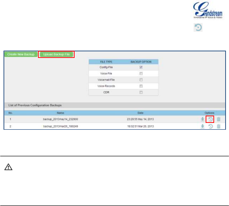
Firmware Version 1.0.0.5
UCM6510 IP PBX User Manual
Page 186 of 192
be displayed in the list of previous configuration backups for restore purpose. Click on to restore
from the backup file.
Figure 97: Restore UCM6510 From Backup File
Note:
The uploaded backup file must be a tar file with no special characters like *,!,#,@,&,$,%,^,(,),/,\,space
in the file name.
The uploaded back file size must be under 10MB.
CLEANER
Users could configure to clean the Call Detail Report/Voice Records/Voice Mails/FAX automatically under
web GUI->Maintenance->Cleaner.
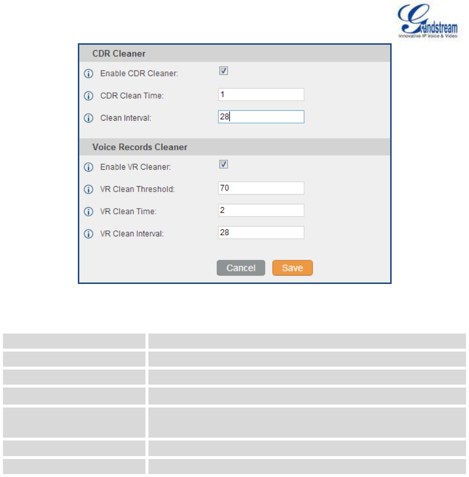
Firmware Version 1.0.0.5
UCM6510 IP PBX User Manual
Page 187 of 192
Figure 98: Cleaner
Table 70: Cleaner Configuration
Enable CDR Cleaner
Enable the CDR Cleaner function.
CDR Clean Time
Enter 0-23 to specify the hour of the day to clean up CDR.
Clean Interval
Enter 1-30 to specify the day of the month to clean up CDR.
Enable VR Cleaner
Enter the Voice Records Cleaner function.
VR Clean Threshold
Specify the Voice Records threshold from 0 to 99 by using local storage
status in percentage.
VR Clean Time
Enter 0-23 to specify the hour of the day to clean up Voice Records.
Clean Interval
Enter 1-30 to specify the day of the month to clean up Voice Records.
All the cleaner logs will be listed on the bottom of the page.
RESET AND REBOOT
Users could perform reset and reboot under web GUI->Maintenance->Reset and Reboot.
To factory reset the device, select the mode type first. There are two different types for reset.
User Data: All the data including voicemail, recordings, IVR Prompt, Music on Hold, CDR and backup
files will be cleared.
All: All the configurations and data will be reset to factory default.
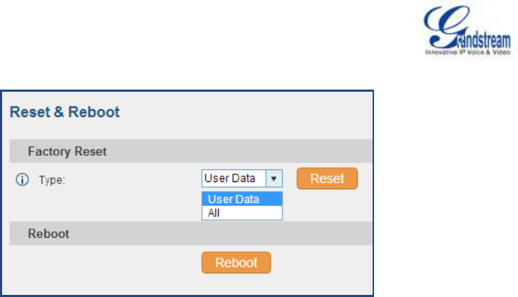
Firmware Version 1.0.0.5
UCM6510 IP PBX User Manual
Page 188 of 192
Figure 99: Reset and Reboot
SYSLOG
On the UCM6510, users could dump the syslog information to a remote server under web
GUI->Maintenance->Syslog. Enter the syslog server hostname or IP address and select the module/level
for the syslog information.
The default syslog level for all modules is "error", which is recommended in your UCM6510 settings
because it can be helpful to locate the issues when errors happen.
Some typical modules for UCM6510 functions are as follows and users can turn on "notic" and "verb"
levels besides "error" level.
pbx: This module is related to general PBX functions.
chan_sip: This module is related to SIP calls.
chan_dahdi: This module is related to analog calls (FXO/FXS).
app_meetme: This module is related to conference bridge.
TROUBLESHOOTING
On the UCM6510, users could capture traces, ping remote host and traceroute remote host for
troubleshooting purpose under web GUI->Maintenance->Troubleshooting.
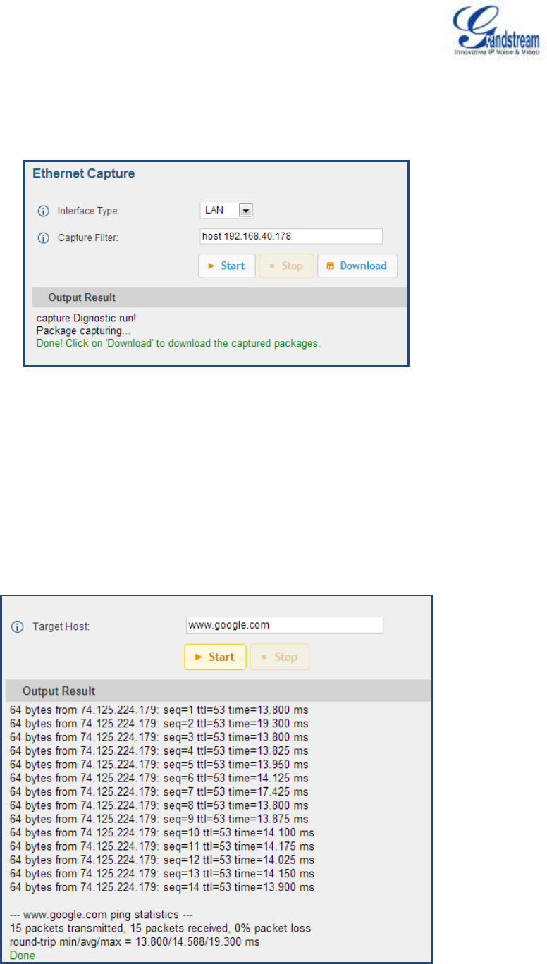
Firmware Version 1.0.0.5
UCM6510 IP PBX User Manual
Page 189 of 192
ETHERNET CAPTURE
The captured trace can be downloaded for analysis. Also the instructions or result will be displayed in the
web GUI output result.
Figure 100: Ethernet Capture
The output result is in .pcap format. Therefore, users could specify the capture filter as used in general
network traffic capture tool (host, src, dst, net, protocol, port, port range) before starting capturing the
trace.
IP PING
Enter the target host in host name or IP address. Then press "Start" button. The output result will
dynamically display in the window below.
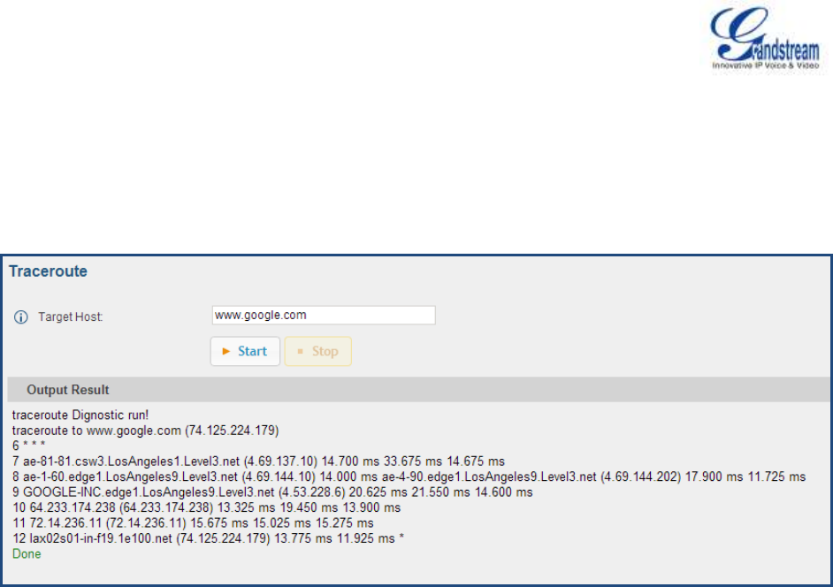
Firmware Version 1.0.0.5
UCM6510 IP PBX User Manual
Page 190 of 192
Figure 101: PING
TRACEROUTE
Enter the target host in host name or IP address. Then press "Start" button. The output result will
dynamically display in the window below.
Figure 102: Traceroute
PRI SIGNALING TRACE
Please see section [DIGITAL TRUNK TROUBLESHOOTING].

Firmware Version 1.0.0.5
UCM6510 IP PBX User Manual
Page 191 of 192
EXPERIENCING THE UCM6510 SERIES IP PBX
Please visit our website: http://www.grandstream.com to receive the most up- to-date updates on firmware
releases, additional features, FAQs, documentation and news on new products.
We encourage you to browse our product related documentation, FAQs and User and Developer Forum
for answers to your general questions. If you have purchased our products through a Grandstream
Certified Partner or Reseller, please contact them directly for immediate support.
Our technical support staff is trained and ready to answer all of your questions. Contact a technical support
member or submit a trouble ticket online to receive in-depth support.
Thank you again for purchasing Grandstream UCM6510 IP PBX appliance, it will be sure to bring
convenience and color to both your business and personal life.
* Asterisk is a Registered Trademark of Digium, Inc.

Firmware Version 1.0.0.5
UCM6510 IP PBX User Manual
Page 192 of 192
FCC Compliance Statement:
This device complies with part 15 of the FCC Rules. Operation is subject to the following two
conditions:(1)This device may not cause harmful interference, and (2) this device must accept any
interference received, including interference that may cause undesired operation.
Important: Any Changes or modifications not expressly approved by the party responsible for compliance
could void the user's authority to operate the equipment.
Note: This equipment has been tested and found to comply with the limits for a Class B digital device,
pursuant to part 15 of the FCC Rules.
These limits are designed to provide reasonable protection against harmful interference in a residential
installation. This equipment generates, uses and can radiate radio frequency energy and, if not installed
and used in accordance with the instructions, may cause harmful interference to radio communications.
However, there is no guarantee that interference will not occur in a particular installation.
If this equipment does cause harmful interference to radio or television reception, which can be determined
by turning the equipment off and on, the user is encouraged to try to correct the interference by one or
more of the following measures:
—Reorient or relocate the receiving antenna.
—Increase the separation between the equipment and receiver.
—Connect the equipment into an outlet on a circuit different from that to which the receiver is connected.
—Consult the dealer or an experienced radio/TV technician for help.