HID Global CEM603 RFID Reader CEM-603 User Manual
HID Global Corporation RFID Reader CEM-603
Manual

June 14, 1999 K01932-000 Rev C
$GYDQWDJH6HULHV3UR[LPLW\
$656HFXUH3UR[70,5HDGHU
$656HFXUH3UR[70,,5HDGHU
,QVWDOODWLRQDQG
2SHUDWLRQ0DQXDO
June 14, 1999 K01932-000 Rev C

June 14, 1999 K01932-000 Rev C iii
Welcome and thank you for choosing Indala’s SecureProxTM I and SecureProxTM II proximity access control
readers, the next generation of our very popular Advantage Series Proximity (ASP) product line.
Your choice of access control readers and credentials from Motorola’s Indala Corporation, the proximity
experts, says that you’ll settle for nothing less than the highest quality proximity products on the market
today. It says your readers have features to simplify installations, save time, and save money. It says your
readers are easier and less expensive to maintain because they include crucial self-test and self-diagnostic
technology. It says your readers can withstand harsh environments. And it says your readers are UL, FCC
and European CE approved. Perhaps most importantly, it says you’re a partner of Motorola’s Indala Corpo-
ration, a company whose first name, Motorola, is virtually synonymous with quality.
FCC Compliance: This device has been tested and found to comply with the limits for Class A digital
device pursuant to Part 15 of the FCC Rules. These limits are designed to provide reasonable protection
against harmful interference when the device is operated in a commercial environment. This device may
not cause harmful interference and must accept any interference received, including interference that may
cause undesired operation. This device uses and generates radio frequency energy and, if not installed and
used in accordance with this manual, may interfere with radio communications.
CE Compliance: This product complies with the European Community Council Directive 89/336/EEC if
the installer/user adheres to the instructions detailed in this manual. The standards specified under
EN50081-1 emission standard and EN50082-1 immunity standard to which this product conforms are
EN55022, IEC 801-2, IEC 801-3, IEC 801-4, and IEC 801-6.
Notice: The ASR-603/605 readers require the use of linear, series pass, regulated power supplies. Use of
other types of power supply can result in reduced read range. The use of switching power supplies is not
recommended.
Do not use the reader`s power supply to power other equipment particularly when operating switched
inductive loads such as motor control relays and solenoids (i.e., magnetic locks, latch or strike). Doing so
will affect the reader operation. Use a separate dedicated power supply to power Indala proximity readers.
Because this technology is based on radio frequency and because nearby environmental sources of electri-
cal interference may affect the performance of the reader, below is a list of precautions that should be con-
sidered when installing or wiring the reader:
•Metal affects radio signals. Do not cover the face of the reader with metal of any kind.
•Reduce or eliminate unwanted signals from external sources.
•Do not place the reader wiring bundled in conduit with AC power cables, lock power, or signal wiring.
•Maintain all reader wiring a minimum distance of 12" (30 cm) away from other wiring to include, but not
limited to AC power, computer data wiring, telephone wiring, or wiring to electric locking devices, etc.
•Do not install the reader in areas where sources of broad spectrum EMI noise may be present. Examples of
EMI broad spectrum noise producers are motors, pumps, generators, AC-DC converters, uninterruptable
power supplies, AC switching relays, light dimmers, computer monitors, and CRTs.
•Do not install the reader within 3.5' (1.1 m) of computer CRTs (monitors).
The rules and regulations of the Federal Communication Commission (FCC) and other regulatory agencies
in various countries limit the RF power level and frequency. The user is cautioned that changes and modi-
fications made to the equipment without the approval of the manufacturer could void the user`s authority to
operate this equipment. It is suggested that the user use only shielded and grounded cables to ensure com-
pliance with FCC Rules.
June 14, 1999 K01932-000 Rev C

June 14, 1999 K01932-000 Rev. C v
7DEOHRI&RQWHQWV
1.0 Overview- - - - - - - - - - - - - - - - - - - - - - - - - - - - - - - - - - - - - - - - - - - - - - - - - - - - - - - - - - - 1
1.1 Introduction. - - - - - - - - - - - - - - - - - - - - - - - - - - - - - - - - - - - - - - - - - - - - - - - - - - - 1
1.2 Features - - - - - - - - - - - - - - - - - - - - - - - - - - - - - - - - - - - - - - - - - - - - - - - - - - - - - - 1
1.3 Specifications - - - - - - - - - - - - - - - - - - - - - - - - - - - - - - - - - - - - - - - - - - - - - - - - - - 2
1.4 Theory of Operation - - - - - - - - - - - - - - - - - - - - - - - - - - - - - - - - - - - - - - - - - - - - - - 3
1.5 Unpacking and Identifying Supplied Parts - - - - - - - - - - - - - - - - - - - - - - - - - - - - - - - 4
1.6 Identifying the Reader Format - - - - - - - - - - - - - - - - - - - - - - - - - - - - - - - - - - - - - - - 4
1.7 Separating ASR-603 Bezel from Electronics Module - - - - - - - - - - - - - - - - - - - - - - - - 5
1.8 Separating ASR-605 Bezel from Electronics Module - - - - - - - - - - - - - - - - - - - - - - - - 5
2.0 Installation - - - - - - - - - - - - - - - - - - - - - - - - - - - - - - - - - - - - - - - - - - - - - - - - - - - - - - - - - 6
2.1 Mechanical Installation - - - - - - - - - - - - - - - - - - - - - - - - - - - - - - - - - - - - - - - - - - - - 6
2.1.1Mullion Mounting - - - - - - - - - - - - - - - - - - - - - - - - - - - - - - - - - - - - - - - - - 6
2.1.2Wall Mounting - - - - - - - - - - - - - - - - - - - - - - - - - - - - - - - - - - - - - - - - - - - 6
2.1.3Mounting Near Metal - - - - - - - - - - - - - - - - - - - - - - - - - - - - - - - - - - - - - - 7
2.1.4Power Supply Cable Types and Maximum Lengths - - - - - - - - - - - - - - - - - - 7
2.1.5Reader to Host Interface Wire Types and Lengths - - - - - - - - - - - - - - - - - - - 8
2.2 Electrical Installation - - - - - - - - - - - - - - - - - - - - - - - - - - - - - - - - - - - - - - - - - - - - - 8
2.2.1Grounding - - - - - - - - - - - - - - - - - - - - - - - - - - - - - - - - - - - - - - - - - - - - - - 8
2.3 Reader to Host Interface Wiring - - - - - - - - - - - - - - - - - - - - - - - - - - - - - - - - - - - - - - 9
3.0 Operation - - - - - - - - - - - - - - - - - - - - - - - - - - - - - - - - - - - - - - - - - - - - - - - - - - - - - - - - - 11
3.1 Presenting the Card - - - - - - - - - - - - - - - - - - - - - - - - - - - - - - - - - - - - - - - - - - - - - 11
3.2 Data Output- - - - - - - - - - - - - - - - - - - - - - - - - - - - - - - - - - - - - - - - - - - - - - - - - - - 11
3.3 QuickFlash™ - - - - - - - - - - - - - - - - - - - - - - - - - - - - - - - - - - - - - - - - - - - - - - - - - 11
3.4 SelfTest™- - - - - - - - - - - - - - - - - - - - - - - - - - - - - - - - - - - - - - - - - - - - - - - - - - - - 12
3.5 Verifying Data at Host - - - - - - - - - - - - - - - - - - - - - - - - - - - - - - - - - - - - - - - - - - - 12
3.6 Controls and Indicators: - - - - - - - - - - - - - - - - - - - - - - - - - - - - - - - - - - - - - - - - - - 12
3.6.1Wiegand and Magnetic Stripe Single-Line Control LED Host to Reader Interface
Wiring: 12
3.6.2 Wiegand Dual-Line Control LED Host to Reader Interface Wiring: - - - - - - -12
3.6.3Option cards: - - - - - - - - - - - - - - - - - - - - - - - - - - - - - - - - - - - - - - - - - - - -13
3.6.3.1Single- and Dual-Line LED Control - - - - - - - - - - - - - - - - - - - - - -13
3.6.3.2QuickFlash™ Beep Enable/Disable - - - - - - - - - - - - - - - - - - - - - -13
3.6.3.3QuickFlash™ LED Enable/Disable - - - - - - - - - - - - - - - - - - - - - -13
3.6.3.4SelfTest™ Card - - - - - - - - - - - - - - - - - - - - - - - - - - - - - - - - - - -13
3.6.3.5WatchDog™ Enable/Disable Card - - - - - - - - - - - - - - - - - - - - - - -13
4.0 Troubleshooting- - - - - - - - - - - - - - - - - - - - - - - - - - - - - - - - - - - - - - - - - - - - - - - - - - - - - 14
5.0 Additional Information - - - - - - - - - - - - - - - - - - - - - - - - - - - - - - - - - - - - - - - - - - - - - - - 15
5.1 Mechanical Drawings - - - - - - - - - - - - - - - - - - - - - - - - - - - - - - - - - - - - - - - - - - - - 15
5.2 Copyrights, Patents, and Trademark Credits - - - - - - - - - - - - - - - - - - - - - - - - - - - - - 17
5.3 RMA (Return Material Authorization)- - - - - - - - - - - - - - - - - - - - - - - - - - - - - - - - - 17
5.4 Contacting Technical Support - - - - - - - - - - - - - - - - - - - - - - - - - - - - - - - - - - - - - - 17
Index - - - - - - - - - - - - - - - - - - - - - - - - - - - - - - - - - - - - - - - - - - - - - - - - - - - - - - - - - - - - 18

vi K01932-000 Rev. C June 14, 1999
/LVWRI)LJXUHV
Figure 1.ASR-603/605 Block Diagram - - - - - - - - - - - - - - - - - - - - - - - - - - - - - - - - - - - -3
Figure 2.603/605 Package Components - - - - - - - - - - - - - - - - - - - - - - - - - - - - - - - - - - - 4
Figure 3. The Reader Label - - - - - - - - - - - - - - - - - - - - - - - - - - - - - - - - - - - - - - - - - - -4
Figure 4.Separating ASR-603 Bezel From Module - - - - - - - - - - - - - - - - - - - - - - - - - - - -5
Figure 5.Separating ASR-605 Bezel From Module - - - - - - - - - - - - - - - - - - - - - - - - - - - -5
Figure 6.Mullion Mounting - - - - - - - - - - - - - - - - - - - - - - - - - - - - - - - - - - - - - - - - - - -6
Figure 7.Wall Mounting - - - - - - - - - - - - - - - - - - - - - - - - - - - - - - - - - - - - - - - - - - - - - -6
Figure 8.Mounting Near Metal Boundary - - - - - - - - - - - - - - - - - - - - - - - - - - - - - - - - - - 7
Figure 9.Grounding the Reader - - - - - - - - - - - - - - - - - - - - - - - - - - - - - - - - - - - - - - - - -8
Figure 10.Reader to Host Interface Wiring - - - - - - - - - - - - - - - - - - - - - - - - - - - - - - - - - 9
Figure 11.Reader Internal Circuit Input and Output Configurations. - - - - - - - - - - - - - - - 10
Figure 12.Presenting the Card - - - - - - - - - - - - - - - - - - - - - - - - - - - - - - - - - - - - - - - - - 11
Figure 13.ASR-603 Mechanical Dimensions - - - - - - - - - - - - - - - - - - - - - - - - - - - - - - - 15
Figure 14.ASR-605 Mechanical Dimensions - - - - - - - - - - - - - - - - - - - - - - - - - - - - - - - 16

June 14, 1999 K01932-000 Rev. C 1
2YHUYLHZ
,QWURGXFWLRQ
The ASR-603 and ASR-605 readers are modular miniaturized and rugged low power radio frequency
readers designed for applications such as identification systems, security systems, and data collection.
The ASR-603 reader mounts on a metal door frame (mullion) or any flat surface. The ASR-605 reader
mounts on any USA standard electrical gang box or on any flat surface. The reader electronics module
is completely enclosed in an epoxy potting material, making it both vandal proof and weather resistant.
The ASR-603 and the ASR-605 use the same reader electronics module. The readers’ bezels can be
interchangeably snapped on the common reader electronics module, enabling the installer to configure
the reader as a wall switch or a mullion reader at the installation site.
The readers output data in Wiegand or Magnetic Stripe formats, making it easy to upgrade an existing
site to proximity using the wiring already in place.
)HDWXUHV
•QuickFlash™ for immediate user feedback.
•SelfTest™ for installer assistance during installation.
•WatchDogTM for increased supervisory control.
•Independently controlled audio tone and tri-color status LED.
•Feld programmability via the use of option cards.
•Snap-on module construction, enabling configuration at installation site.
•Mounting on standard electrical box or on any flat surface.
•Indoor/outdoor operation.
•Attractive, contemporary styling.

2 K01932-000 Rev. C June 14, 1999
6SHFLILFDWLRQV
●Input Voltage: 4.0 VDC to 16 VDC
●Input Current/Power:
-Typical, quiescent off metal Vin = 5.0 DC 86 mA 0.43 W
Vin =12.0 VDC 65 mA 0.78 W
-Maximum with card present
and reader mounted on metal 4.0 VDC < Vin < 16 VDC 100 mA 0.400-1.60 W
●Power Supply:
-Recommendation Regulated linear power supply
●Read Range:
-With ASC-121T LifeTimeTM Card Up to 5.0" (12.7 cm)
-With ASK-116T KeyTag Up to 3.0" (7.6 cm)
-With AVC-132 Image100TM Up to 4.0" (10.2 cm)
●Frequency:
-Exciter Field 125 KHz
-Receive 62.5 KHz
●Operating Temperature Range: -35° C to +65° C (-31° F to +149° F)
●Color: Black and sand beige
●Material: UV resistant, ABS (UL 94V0) plastic
●Weight (typical): 5 oz. (142 g)
●Dimensions:
-ASR-603 4.50"H x 1.72"W x 0.85"T (11.42 x 4.37 x 2.16cm)
-ASR-605 4.50"H x 2.99"W x 0.85"T (11.42 x 7.59 x 2.16cm)
●Output Formats: Wiegand and ABA track 2 magnetic stripe
●Certification: UL-294 indoor and outdoor compliant, CE Mark, and
FCC Class A Digital Device (Part 15) ID Numbers
E9U503 and E9U505.
Read range is stated in an undisturbed electrical environment, with card presented parallel to reader,
and reader installed in accordance with Indala instructions. Mounting the ASR-603/605 on metal
slightly decreases the read range. Power supply, reader, and controller must be on the same ground,
connected to earth.
•
June 14, 1999 K01932-000 Rev. C 3
7KHRU\RI2SHUDWLRQ
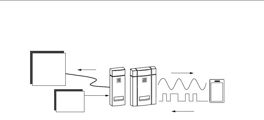
Figure 1. ASR-603/605 Block Diagram
When the reader is powered, a low-power radio frequency (RF) field is continuously transmitted by
the reader (see figure 1). When a card is presented within the field of the reader, the microchip, embed-
ded in the card, is activated and transmits a unique identification (ID) number back to the ASR-603/
605 reader. The reader decodes and converts this data to the pre-determined Wiegand, or Magnetic
Stripe compatible format and sends this code to an external controller through data cables. With this
information, the controller determines what action is to be taken as a response to the card presentation.
Card
Field From R eader
Energizes C ard
C ard S ends D ata
To R eader
R eader
S ends D ata to
H o s t C o m p u te r
Power
Power
Supply
C o n tr o lle r
A S R -6 0 3 o r A S R -6 0 5
4 K01932-000 Rev. C June 14, 1999
8QSDFNLQJDQG,GHQWLI\LQJ6XSSOLHG3DUWV
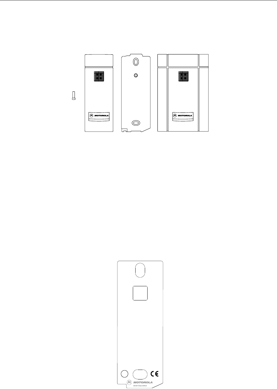
Figure 2. 603/605 Package Components
Unpack the equipment and become familiar with the components. The following list describes the con-
tent of the package (see Figure 2. ):
ASR-603 Package: Tamper screw, reader electronics module, and ASR-603 bezel.
ASR-605 Package: Tamper screw, reader electronics module, and ASR-605 bezel.
,GHQWLI\LQJWKH5HDGHU)RUPDW
The reader format is typed on the ID label (see Figure 3. ) on the reader electronics module.
Figure 3. The Reader Label
Tam per
Screw
ASR-603
Bezel R eader
Electronics
M odule
ASR-605
Bezel
This device complies with Part 15 of the
FCC rules. Operation is subject to the
following two conditions: (1) This device
may not cause harmful interference.
And (2) this device must accept any
interference received, including
interference that may cause undesired
operation. Patents: US#4818855,
Canada#1253591. Made in USA.
FCC ID:
E9U503
Model:
ASR-603
S/N:
N*11996333
Manual:
K01932-001
Power:
See Manual
For Technical Support Call:
1-800-M INDALA (1-800-646-3252)
Format:
26 Bit Wiegand-2L
ACCESS CONTROL
UNIT ACCESSORY
SUITABLE FOR
OUTDOOR USE.
BP6430
LISTED
5T77
UL
June 14, 1999 K01932-000 Rev. C 5
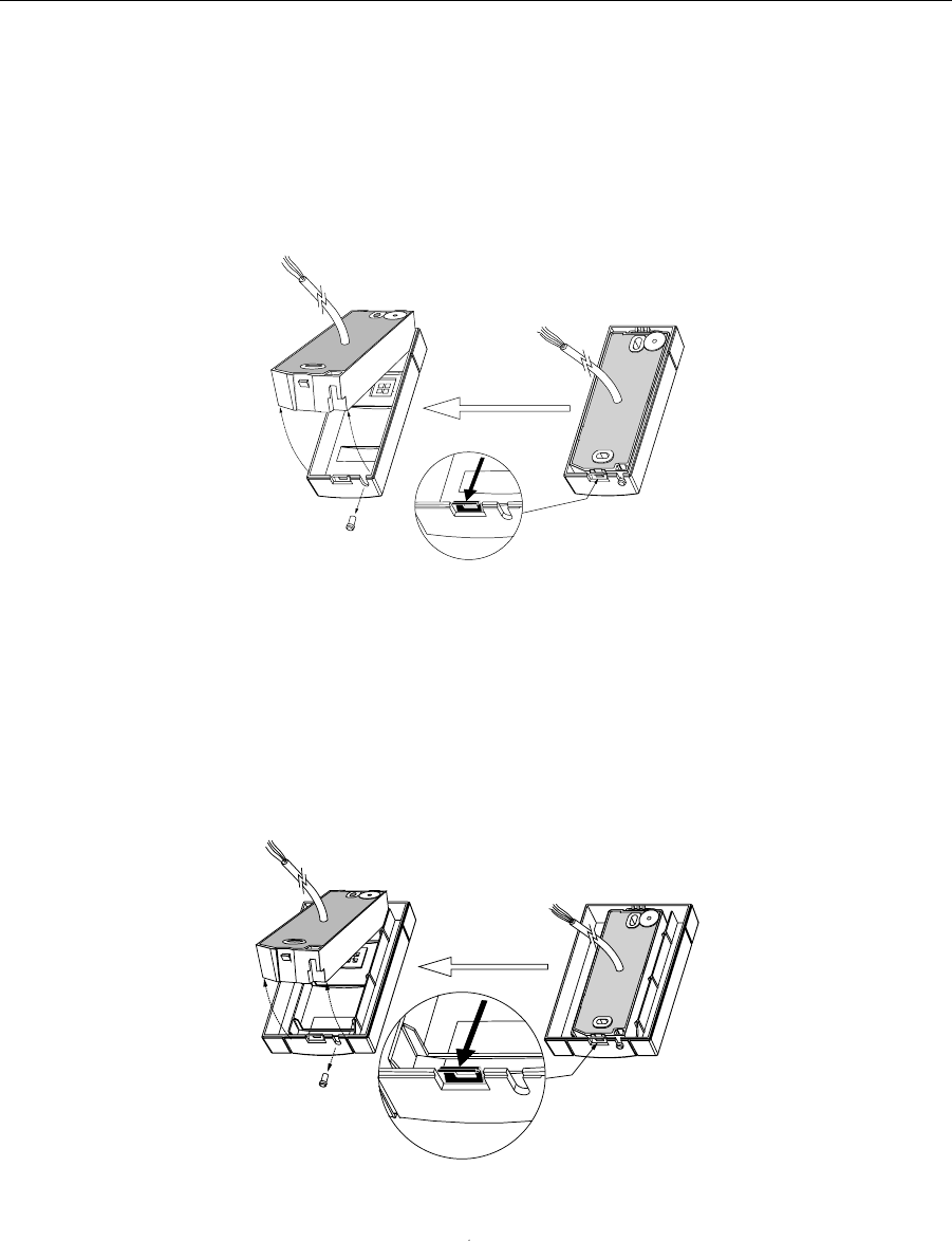
6HSDUDWLQJ$65%H]HOIURP(OHFWURQLFV0RGXOH
To remove the ASR-603 reader bezel, unscrew the tamper screw, pull metal latch, and pull the reader
module up as shown in Figure 4.
Figure 4. Separating ASR-603 Bezel From Module
6HSDUDWLQJ$65%H]HOIURP(OHFWURQLFV0RGXOH
To remove the ASR-605 reader bezel, unscrew the tamper screw, pull metal latch, and pull the reader
module up as shown in Figure 5.
Figure 5. Separating ASR-605 Bezel From Module
6 K01932-000 Rev. C June 14, 1999
,QVWDOODWLRQ
0HFKDQLFDO,QVWDOODWLRQ
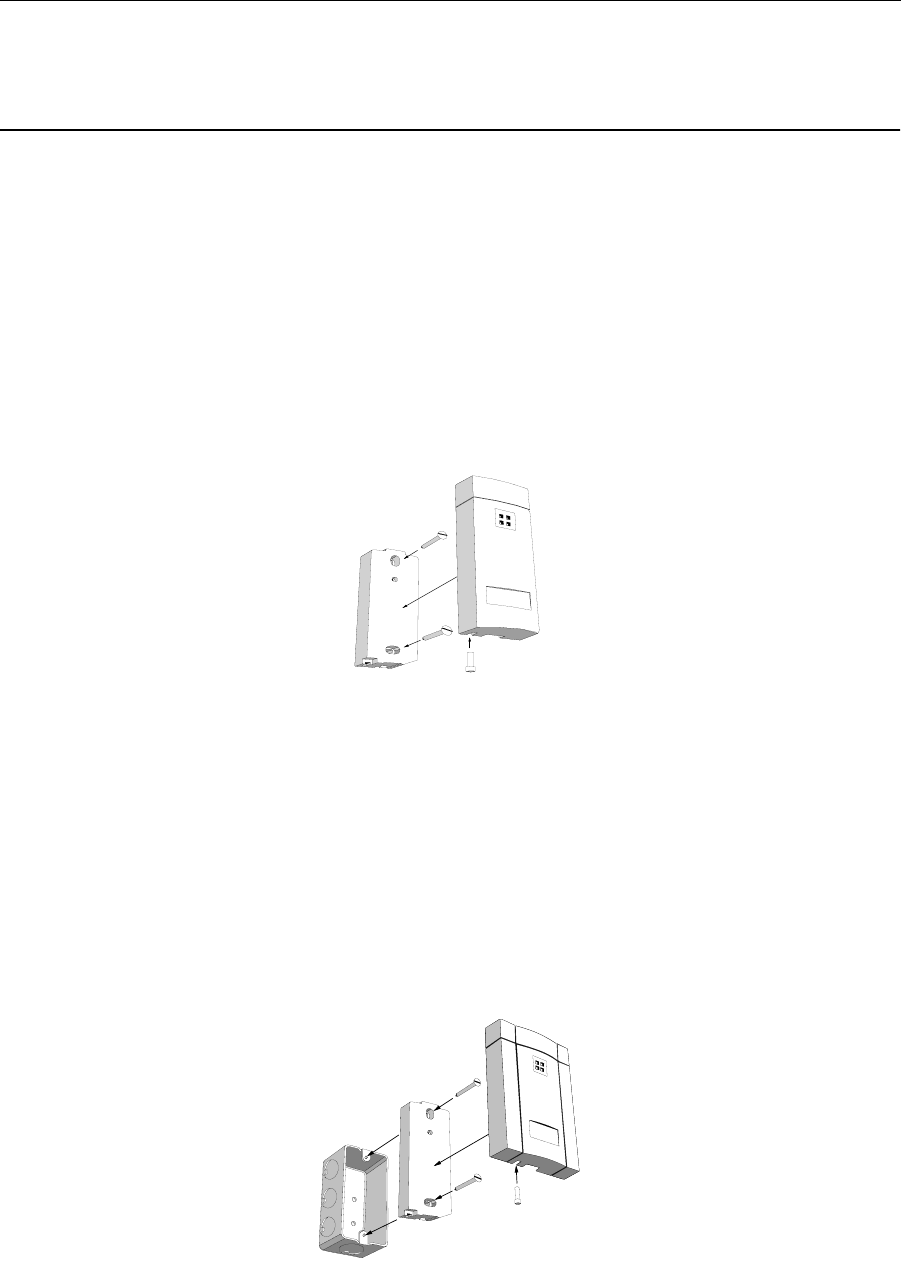
0XOOLRQ0RXQWLQJ
To mount the ASR-603 to a mullion, drill two proper size holes (for 6-32 sheet metal or thread forming
screws) 3.3" apart. At center of these two holes drill a 0.375" hole for the reader cable. Route the cable
through the center hole to the controller. Using the two 6-32 screws attach the reader to the first two
holes. Once the reader module is screwed in place, snap on the ASR-603 bezel then install the tamper
screw as shown in Figure 6. For mechanical dimensions of the ASR-603 refer to section 5.0 "Addi-
tional Information".
Figure 6. Mullion Mounting
:DOO0RXQWLQJ
To wall mount the reader there are two choices. The first choice is to mount the reader directly to the
wall. This is similar to the mullion mounting described above. The second choice is to mount it on a
gang box. When installing the reader on an electrical gang box, make sure the gang box mounting
holes fit the reader mounting holes. Using two 6-32 screws, attach the reader to the gang box. Once the
reader module is screwed in place, snap on the reader bezel then install the tamper screw as shown in
Figure 7. For mechanical dimensions of the ASR-603 or ASR-605, refer to Section 5.0 (Mechanical
Drawings).
Figure 7. Wall Mounting
June 14, 1999 K01932-000 Rev. C 7
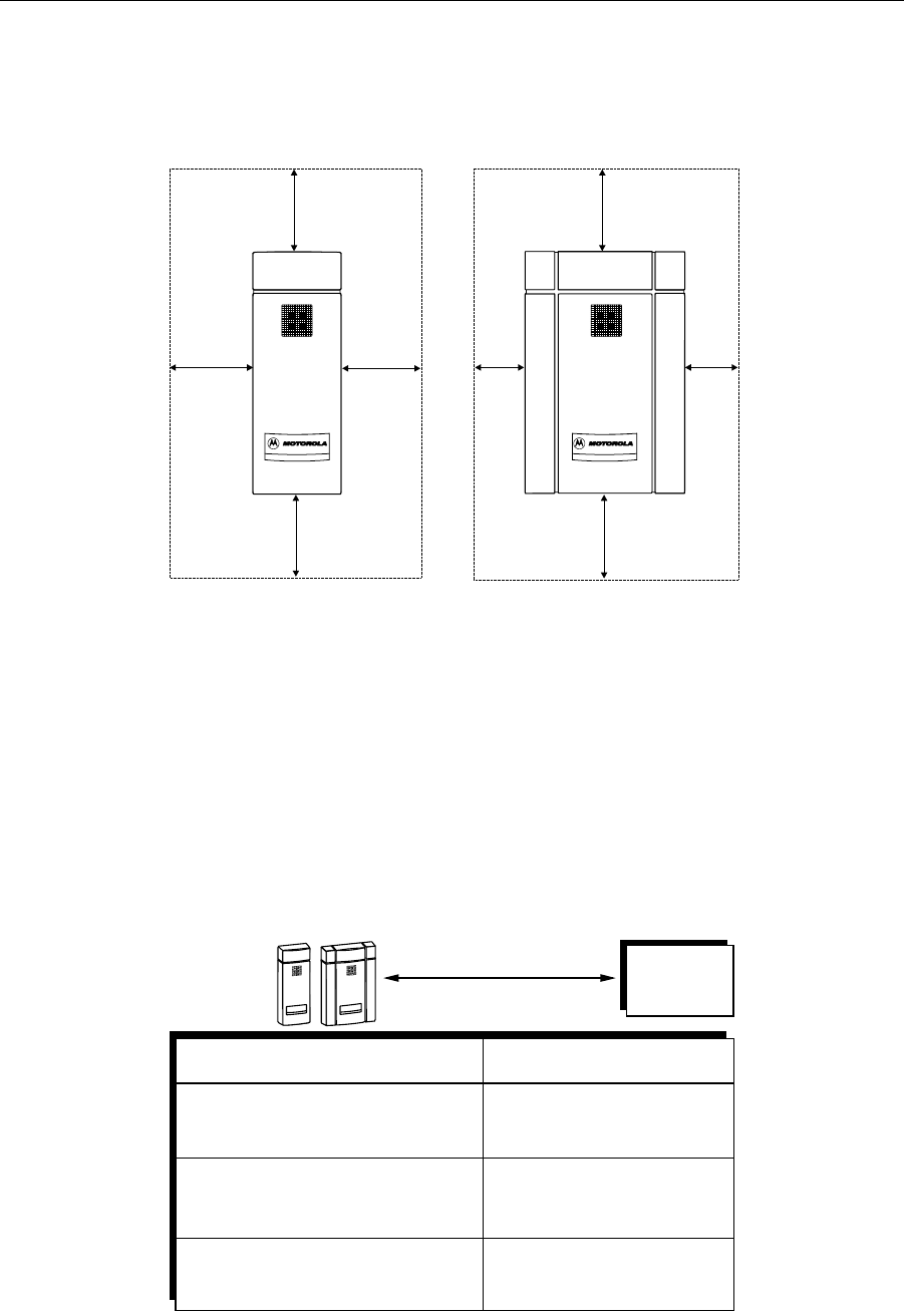
0RXQWLQJ1HDU0HWDO
When mounting the ASR-603 or ASR-605, observe the near metal boundaries as shown in Figure 8.
Figure 8. Mounting Near Metal Boundary
3RZHU6XSSO\&DEOH7\SHVDQG0D[LPXP/HQJWKV
The ASR-603/605 reader requires a minimum voltage of 4.0 VDC. Voltage drops, caused by the cable
resistance, can be made up by increasing the power supply voltage (DO NOT SET THE POWER
SUPPLY VOLTAGE TO HIGHER THAN 16 VDC). In noisy environments, use shorter cable runs.
The following are the recommended cable types and maximum cable lengths for cables connecting the
power supply to the reader (DO NOT USE CABLES WITH GAUGES SMALLER THAN 24
AWG)
ASR-603
Bezel ASR-605
Bezel
1.5 “
1.5”
1.5”
1.5”
1.5”
1” 1”
1.5”
MINIMUM
METAL BOUNDARY
MINIMUM
METAL BOUNDARY
Cable Type
Power
Supply
200' (61 m )
300' (91 m )
Cable Length
ASR-603
or A SR -605
R eader
24 A W G (0.60 m m ), three conductor,
w ith an overall foil shield, B elden, 9533
or equivalent.
22 A W G (0.80 m m ), tw o conductor,
w ith a n o v e ra ll fo il sh ie ld , A lp h a 5 1 9 2
or equivalent.
500' (152 m )
18 A W G (1.20 m m ), tw o conductor,
w ith an overall foil shield, A lpha 5386
or equivalent.
M axim um C able Length
8 K01932-000 Rev. C June 14, 1999
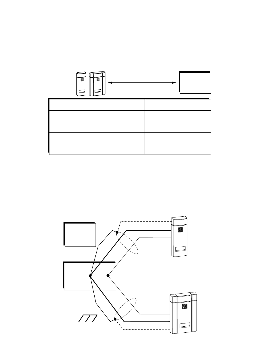
5HDGHUWR+RVW,QWHUIDFH:LUH7\SHVDQG/HQJWKV
Refer to the table below to determine the recommended wiring type at various maximum distances.
Variation in distance requires different wire gauges. Because of system data termination differences,
contact your system manufacturer for its exact requirements. Installation to be in accordance with
National Electric Code ANSI/NFPA 70.
(OHFWULFDO,QVWDOODWLRQ
*URXQGLQJ
Figure 9. Grounding the Reader
Connect the power supply and the controller directly to an earth ground. An earth ground can be estab-
lished by driving a cpper clad ground rod into the earth. Make certain the DC resistance between your
Cable Type
Host
C o n tro lle r
500' (152 m )
Cable Length
M a x im u m C a b le L e n g th
22 A W G (0.80 m m ), six or eight conductor,
w ith an overall foil shield, A lpha, 5196,
5198 or equivalent.
18 A W G (1.20 m m ), six or eight conductor,
w ith an overall foil shield, A lpha 5386,
5388 or equivalent.
500' (152 m )
ASR-603
or A S R -605
R eader
Linear
Power
Supply
Earth
Ground
(-) (+)
ASR-603
ASR-605
Host
Controller
GND
June 14, 1999 K01932-000 Rev. C 9
established earth ground and the system ground is 50 Ohms or less. If direct connection to a ground
rod is not possible, connect the reader to an earth grounded cold water metal pipe (do not connect to
copper fire sprinkler system because it may have non-conductive couplings), or steel frames (building
beams) that connect to earth.
Prevent ground loops by connecting both the cable shield and the negative line of the power supply to
one common earth ground point. Connecting different points to separate earth grounds may result in a
ground loop. Ground loops may cause poor read range and communication line interference resulting
in no code or improper code being seen by the controller.
In a multiple reader installation, connect all readers to a single earth ground reference point (common
ground).
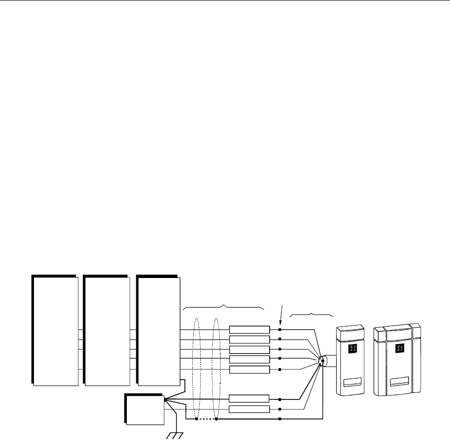
5HDGHUWR+RVW,QWHUIDFH:LULQJ
Figure 10. shows all the possible interfaces. Chose the appropriate interface for your installation.
Figure 10. Reader to Host Interface Wiring
Notes:
•The system must have a single earth ground point.
•Connect screen (shield) wire at ASR-603/605 reader cable splice to a common earth ground as
shown.
•For open collector (non-terminated output), consult your system manufacturer for correct cable length
and type.
•The internal circuit configurations for the reader inputs and outputs are as shown in Figure 11.
EARTH GROUND
Color
Code
Reader Cable
Green
Brown
Black
Red
White
Splice Here
Extension Cable
Blue
Orange
ASR-603 OR ASR-605
Beeper Out
Strobe/Clk In
Data in
LED Out
Card Present
GND (0V)
Beeper Out
Data '1' In
Data '0' In
Red LED Out
Green LED Out
GND (0V)
Host
Controller
Wiegand
Single Line
LED Control
Beeper Out
Data '1' In
Data '0' In
Multi-Color
LED Out
GND (0V)
Do Not Connect
Multi-Color
4-16VDC
Linear
Power
Supply
+
-
Shield ( Screen )
Host
Controller
Wiegand
Dual Line
LED Control
Host
Controller
Magnetic Stripe
Single Line
LED Control
10 K01932-000 Rev. C June 14, 1999
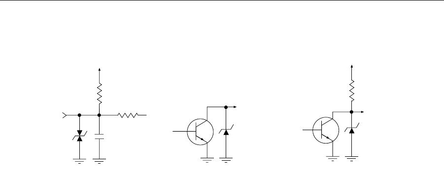
Figure 11. Reader Internal Circuit Input and Output Configurations.
+5VD C
INPUT CIRCUIT CONFIGURATION
47K
10K
0.001uF
SM B15C
IN P U T
2N 4401
O P E N C O L L E C T O R O U T P U T
SM B15
OUTPUT
2N 4401
+5VD C
TERMINATED OUTPUT
820
SM B15
OUTPUT
June 14, 1999 K01932-000 Rev. C 11
2SHUDWLRQ
When power is first applied to the reader, it performs an internal circuit Self Test™. If it appears to be
functioning properly, the reader will flash the amber LED and beep twice. After the SelfTest™ is com-
pleted, the reader is in a READY status mode and you may present the card to the reader.
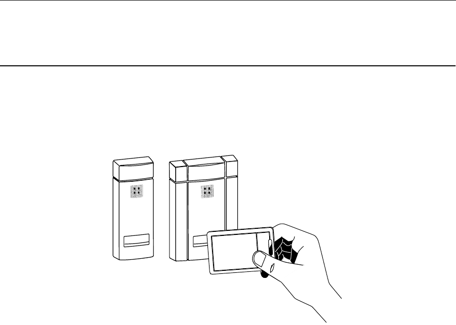
Figure 12. Presenting the Card
3UHVHQWLQJWKH&DUG
To obtain maximum read range, present the card to the reader as shown in Figure 12. Keeping the
card parallel to the ASR-603 or ASR-605 reader, move it slowly toward the face of the reader until a
QuickFlash™ (refer to section 3.3 ) is obtained. This is the point at which the card is read and the data
is transmitted to the controller. To read the card again, remove it from the antenna field and present it
again. During normal use, the card can be presented to the antenna at any angle, although this will
result in a reduced read range.
'DWD2XWSXW
Both ASR-603 and ASR-605 readers are capable of outputting in either Wiegand or magnetic stripe
formatted data. For further information please call technical support at (800)646-3252.
4XLFN)ODVK
When a valid card is presented, unless QuickFlash™ is activated, the LED will flash and the audio
tone (beeper) will be activated for 70 to 100 milliseconds, regardless of the card`s access status. This
gives the user immediate feedback that the card was read and the data was sent to the controller. After
the 100 millisecond QuickFlash™ period, the controller takes over the control of the LED and beeper.

12 K01932-000 Rev. C June 14, 1999
6HOI7HVW
The readers have an internal diagnostic routine to assure reader operation at start-up, as well as a
means to test the integrity of the data lines. When power is first applied to a reader, it will “beep and
flash” twice to let the installer know that it has performed an internal check and appears to be function-
ing properly. If the reader start-up routine determines one of the critical memory devices inside the
reader has failed, the reader will emit a “chirping” sound.
9HULI\LQJ'DWDDW+RVW
To verify that the controller can read the data, put the reader into “line test mode” by holding a SelfT-
est™ card (Indala part number 07257-001) in front of the reader. The reader will respond with an alter-
nately flashing LED in all three colors and an audio signal to let you know it is in the line test mode.
The reader will remain in the line test mode until power is removed and reapplied or the SelfTest™ card
is presented again. While in this mode, the reader will send output pulses down the data lines at a 1 Hz
rate, which can be measured at the controller end with a volt meter. If the pulses are not present, then
there is probably a break or short in the line. If the pulses are present and the system is still not working,
the reader may not be connected to the controller properly, the controller/system may be incorrectly
programmed, or the controller may be broken.
&RQWUROVDQG,QGLFDWRUV
:LHJDQGDQG0DJQHWLF6WULSH6LQJOH/LQH&RQWURO/('+RVWWR5HDGHU,QWHUIDFH:LULQJ
•There is no LED OFF state in this configuration. LED is red when the brown wire is high
(above 2.2 VDC or not connected).
•Pull brown wire low to change LED color to green.
•Toggle brown line high-low at a rate of 100 Hz to 1 kHz, 50% duty cycle, to produce amber
LED color.
•Pull blue beeper wire low to activate audio beep tone.
:LHJDQG'XDO/LQH&RQWURO/('+RVWWR5HDGHU,QWHUIDFH:LULQJ
•The LED is OFF when both brown and orange wires are high (above 2.2 VDC or not con-
nected).
•Pull brown wire low to activate red LED.
•Pull orange wire low to activate green LED.
•Pull orange and brown wires low simultaneously to activate amber LED.
•Pull blue wire low to activate audio “beeper” tone.

June 14, 1999 K01932-000 Rev. C 13
2SWLRQFDUGV
6LQJOHDQG'XDO/LQH/('&RQWURO
This option card toggles the state of the LED control lines (Indala part number 07260-001). If one beep
is heard when the card is presented, the reader is set to a single line LED control. If two beeps are
heard, the reader is set to a dual line LED control.
4XLFN)ODVK%HHS(QDEOH'LVDEOH
This option card toggles the state of the QuickFlash™ beep option (Indala part number 07259-001). If
one beep is heard when the card is presented to the reader, the automatic beep is enabled. If two beeps
are heard, the automatic beep is disabled.
4XLFN)ODVK/('(QDEOH'LVDEOH
This option card toggles the state of the QuickFlash™ LED option (Indala part number 07258-001). If
one beep is heard when the card is presented to the reader, the automatic QuickFlash™ is enabled. If
two beeps are heard, the automatic QuickFlash™ is disabled.
6HOI7HVW&DUG
This option card enables or disables the SelfTest™ mode upon presentation (Indala part number
07257-001). Present the card once to enable the SelfTest™ mode. Present a second time to revert to
normal operation.
:DWFK'RJ(QDEOH'LVDEOH&DUG
This option card toggles the state of the automatic WatchDogTM option (Indala part number 07508-
001). If one beep is heard when the card is presented to the reader, the WatchDogTM output is enabled.
If two beeps are heard, the WatchDogTM output is disabled. The WatchDogTM output will output an 8
bit “10101010” pattern approximately once per minute over the data lines. This option card is avail-
able with either wiegand or magnetic stripe interfaces.

14 K01932-000 Rev. C June 14, 1999
7URXEOHVKRRWLQJ
If the reader does not function properly when installed according to instructions, please complete this
form and fax it to (408) 434-7057 before calling (800) 646-3252 for technical assistance. International
customers call (408)383-4000:
FAX
From: _________________________________________________ To: Technical Support
Phone: ________________________________________________ Model: ASR-603/605
Fax:___________________________________________________ Fax: (408) 434-7057
Product S/N ____________________________________________ Date:______________
Dead Reader
1. Is the reader wired according to instructions? o Yes o No
2. Is the recommended power supply being used? o Yes o No
3. Is the DC voltage correct? o Yes, __________ volts o No
4. Is the DC current correct? o Yes __________ ma o No
5. What is the cable length between the power supply and the reader?____ feet
6. Is the cable type according to specifications? o Yes o No
Short Read Range
1. Is the reader wired according to instructions? o Yes o No
2. Is earth ground connected according to instructions? o Yes o No
3. Is the cable shield connected according to instructions? o Yes o No
4. Is the recommended power supply being used? o Yes o No
5. Is the DC voltage correct? o Yes, __________ volts o No
6. Is the DC current correct? o Yes __________ ma o No
7. Is there a CRT (computer monitor) nearby? o Yes __________ feet o No
8. Is the card presentation according to instructions? o Yes o No
9. What is the card/tag number? Card model number:______________
Data Incorrect or Non-existent
1. At reader power up, did reader exhibit SelfTestTM ?o Yeso No
2. Upon card presentation, did reader exhibit QuickFlashTM ?o Yeso No
3. If you answered Yes to question 1 and 2, put the reader into line test mode
as detailed in section 3.5 "Verifying Data at Host".
4. Is the reader wired according to instructions? o Yes o No
5. Is earth ground connected according to instructions? o Yes o No
6. Is the cable shield connected according to instructions? o Yes o No
7. Is there a CRT (computer monitor) nearby? o Yes __________ feet o No
8. Is the card presentation according to instructions o Yes o No
9. What is the reader format? Reader format:_________________
June 14, 1999 K01932-000 Rev. C 15
$GGLWLRQDO,QIRUPDWLRQ
0HFKDQLFDO'UDZLQJV
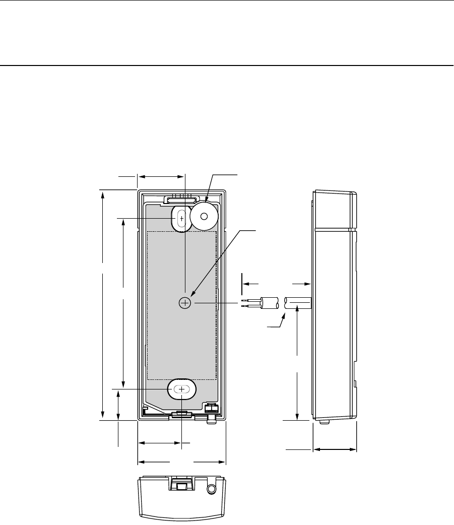
Figure 13. ASR-603 Mechanical Dimensions
0.86
4.50
1.72
0.85
0.60
Cable
2.18
3.34
0.88
18.00
Cable
0.25 O D
Beeper

16 K01932-000 Rev. C June 14, 1999
Figure 14. ASR-605 Mechanical Dimensions
3.34
2.99
1.49
0.85
4.50
Cable
2.18
18.00
1.52
Cable
0.25 O D
Beeper

June 14, 1999 K01932-000 Rev. C 17
&RS\ULJKWV3DWHQWVDQG7UDGHPDUN&UHGLWV
© 1997 Indala Corporation. Motorola`s Indala Corporation reserves all rights including patents, copy-
rights, trademarks, trade names, and all other intellectual property rights worldwide. No reproduction,
adaptation, or translation is allowed without prior written permission from Motorola`s Indala Corpora-
tion. Indala Corporation reserves the right to change any product description and/or specification con-
tained here without prior notice.
Products are covered by United States patent 4818855, Canadian patent 1253591, and other patents
pending worldwide.
Motorola and the Motorola logo are registered trade marks of Motorola, Inc. ASP, SelfTest™, Quick-
Flash™, and WatchDogTM are trade marks of Indala Corporation.
50$5HWXUQ0DWHULDO$XWKRUL]DWLRQ
Goods returned for repair, warranty or non-warranty, must be assigned an RMA (Return Material
Authorization) number. The customer is to provide a description of the specific problem. The customer
is to include serial numbers, formats, card ID numbers, and correct facility codes with the items to be
returned. If exact duplicates of returned cards or tags are requested, the customer must provide Motor-
ola Indala with the exact format and ID numbers needed.
For readers returned and not covered by the warranty (due to age, misuse and/or damage), a quote for
repairs will be issued, and no work will be performed until a valid purchase order is received. Read-
ers left over 30 days without a repair authorization and a purchase order will be returned with evalua-
tion charges and shipping costs applied.
&RQWDFWLQJ7HFKQLFDO6XSSRUW
Please answer all questions in section 4.0 "Troubleshooting" and have your answers ready before you
call the technical support number listed below:
U.S.A. Office:
3041 Orchard Parkway
San Jose, CA 95134-2017
Tel (408) 383-4000, Main
Tel (800) 646-3252, Technical Support
Fax (408) 434-7057

June 14, 1999 K01932-000 Rev. C 18
A
a quote for repairs 17
Additional Information 15
alternately flashing LED, 3 colors 12
amber LED 11
and tri-color status LED 1
applications 1
ASC-121T LifeTimeTM Card 2
ASK-116T KeyTag 2
ASP Advantage Series Proximity iii
ASR-603 1
ASR-603 bezel 4, 6
ASR-603 dimensions 2
ASR-603 Package 4
ASR-603 reader bezel, 5
ASR-605 1
ASR-605 bezel 4
ASR-605 dimensions 2
ASR-605 Package 4
assigned a RMA 17
assigned a RMA (Return Material Authorization)
num 17
audio tone 1
audio tone (beeper) 11
automatic beep 13
automatic QuickFlash™ 13
automatic WatchDogTM 13
AVC-132 Image100TM 2
B
beep 11
Beep Enable/Disable 13
beeper control 11
bezels 1
blue wire 12
break or short in line 12
brown wire 12
C
cable length 9
cable resistance 7
cable shield 9
cable splice 9
calling technical support 14
Canadian patent 17
card 2, 3
card ID numbers 17
card's access status 11
CE Compliance iii
CE Mark 2
Certification 2
chirping sound 12
cold water metal pipe 9
Color (reader) 2
common earth ground 9
common ground 9
communications line interference 9
compliant 2
components 4
connecting the power supply to the reader 7
contemporary styling 1
controller 2, 3, 11
controller can read the data 12
Controls and Indicators 12
copper fire sprinkler system 9
correct facility codes 17
cpper clad ground rod 8
CRT (Computer Monitor) 14
D
data 11
Data Incorrect or Non-existent 14
data is transmitted 11
data lines 12
Data Output 11
DC current 14
DC resistance 8
DC resistance between your established earth
groun 8
DC resistance, earth ground 9
DC voltage 14
Dead Reader 14
description of the specific problem 17
Dimensions 2
E
earth 2, 8
earth ground 8, 9
Earth ground can be established by 8
electrical box 1
electrical environment 2
electrical gang box 1, 6
Electrical Installation 8
epoxy potting material 1
evaluation charges and shipping costs 17
exact duplicates of returned cards or tags 17
,QGH[

June 14, 1999 K01932-000 Rev. C 19
Exciter Field 2
F
fax 14
FCC Class A 2
FCC Compliance iii
Features 1
Field programmability 1
flash 11, 12
form (for technical support) 14
format 3
formats 17
formats, output data 1
Frequency
2
functioning properly 11
G
gang box 6
Goods returned 17
green LED 12
ground 2
ground loop 9
ground loops 9
Grounding the Reader 8
H
Host to Reader Interface 12
I
ID label 4
Identifying the Reader Format 4
improper code 9
Indoor outdoor operation. 1
Input Current/Power 2
Input Voltage 2
Installation 6
installer 12
integrity of data lines 12
intellectual property 17
internal check 12
internal circuit configurations 9
internal circuit self test 11
internal diagnostic routine 12
L
LED 11, 12, 13
LED color 12
LED OFF state 12
line test mode 14
M
Magnetic Stripe 12
magnetic stripe 1, 2, 3, 11, 13
Material 2
maximum cable lengths 7
maximum read range 11
mechanical dimensions 6
Mechanical Drawings 6, 15
Mechanical Installation 6
model number 14
modular (reader) 1
mount 1
Mounting 1, 2
mullion 1
Mullion Mounting 6
multiple reader installation 9
N
National Electric Code ANSI/NFPA 70 8
negative line 9
no code 9
noisy environments 7
non-conductive couplings 9
non-warranty 17
normal operation 13
not covered by the warranty 17
Notice iii
O
open collector (non-terminated output) 9
Operating Temperature Range 2
Operation 11
Option cards 13
option cards 1
orange wire 12
output data 1
Output Formats 2
output pulses 12
outputting (data) 11
over 30 days (no authorization) 17
Overview 1
P
Part 15 2
Patents 17
patents pending 17
poor read range 9
power 11
Power Supply 2, 7
Power supply 2
power supply 8, 9, 14
Power Supply Cable Types and Maximum
Lengths 7
power supply voltage 7

20 K01932-000 Rev. C June 14, 1999
present the card 11
Prevent ground loops 9
product description 17
Product S/N 14
pulses 12
purchase order 17
Q
QuickFlash 11
QuickFlash™ 1, 11, 13, 17
quote for repairs 17
R
Read Range 14
read range 2, 9, 11
read the card again 11
reader 1, 2, 12, 14
reader bezel 5, 6
reader electronics module 1, 4
Reader Format 4
reader input output circuits 9
reader module 6
reader operation at startup 11
Reader to Host Interface Wire Types and Lengths
8
Reader to Host Interface Wiring 9
readers returned 17
READY status mode 11
Receive 2
Receive, frequency 2
recommended cable types 7
recommended wiring type 8
red LED 12
reduced read range 11
registered trademarks 17
Regulated linear power supply 2
repair 17
repair authorization 17
reproduction (rights) 17
returned readers 17
RF field 3
RMA (Return Material Authorization) 17
S
screen (shield) 9
SecureProxTM I iii
SecureProxTM II iii
self test 11
SelfTestTM 1
SelfTest™ 13
SelfTest™ mode 13
separate earth grounds 9
serial numbers 17
shield (screen) 9
Short read range 14
single and dual line LED control 13
single earth ground 9
Snap on module 1
Specifications 2
start-up routine 12
steel frames (building beams) 9
system 9
T
tag 14
Tamper screw 4
tamper screw 6
technical assistance international 14
Technical Support 17
technical support number 11
The Reader Label 4
Theory of Operation 3
Toggle 12
translation 17
transmit 3
Troubleshooting 14
U
UL-294 2
United States patent 17
Unpacking and Identifying Supplied Parts 4
user immediate feedback 11
U.S.A. Office 17
V
Verifying data at host 12
voltage 7
Voltage drops 7
W
wall mount 6
wall switch 1
warranty 17
WatchDog™ 13
WatchDog™ enable/disable 13
Weight 2
weight (reader) 2
Wiegand 11
wiegand 1, 11
wire gauges 8
wired 14
wires 12