HM Electronics BASE6000 BASE STATION 6000 User Manual 400519a
HM Electronics Inc BASE STATION 6000 400519a
UserManual.wiki
>
HM Electronics
>
BASE6000 User Manual
>
User Manual
Contents
1.
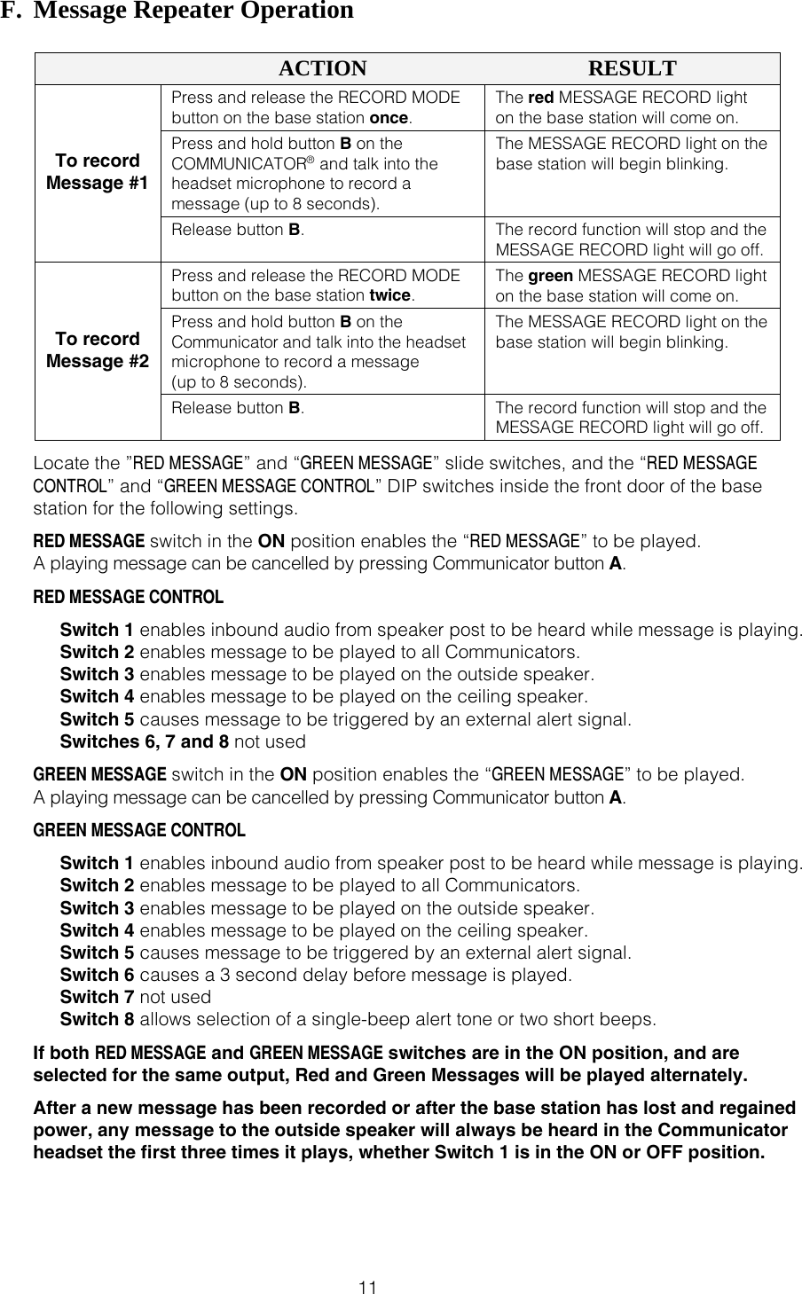
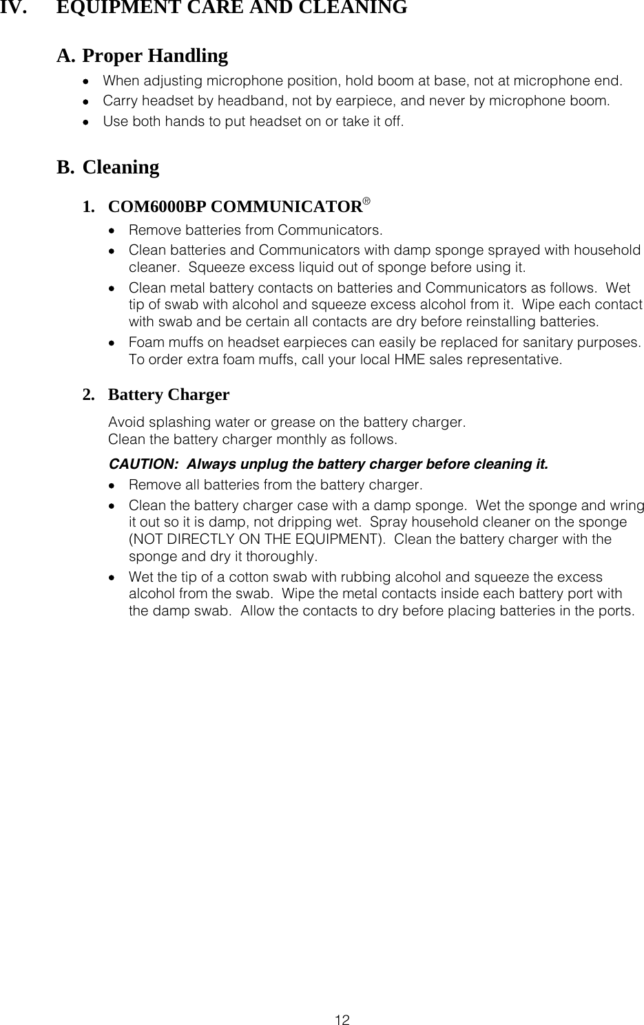
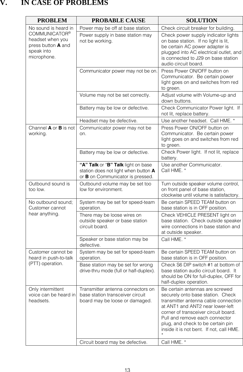
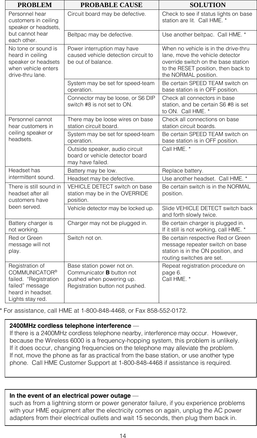
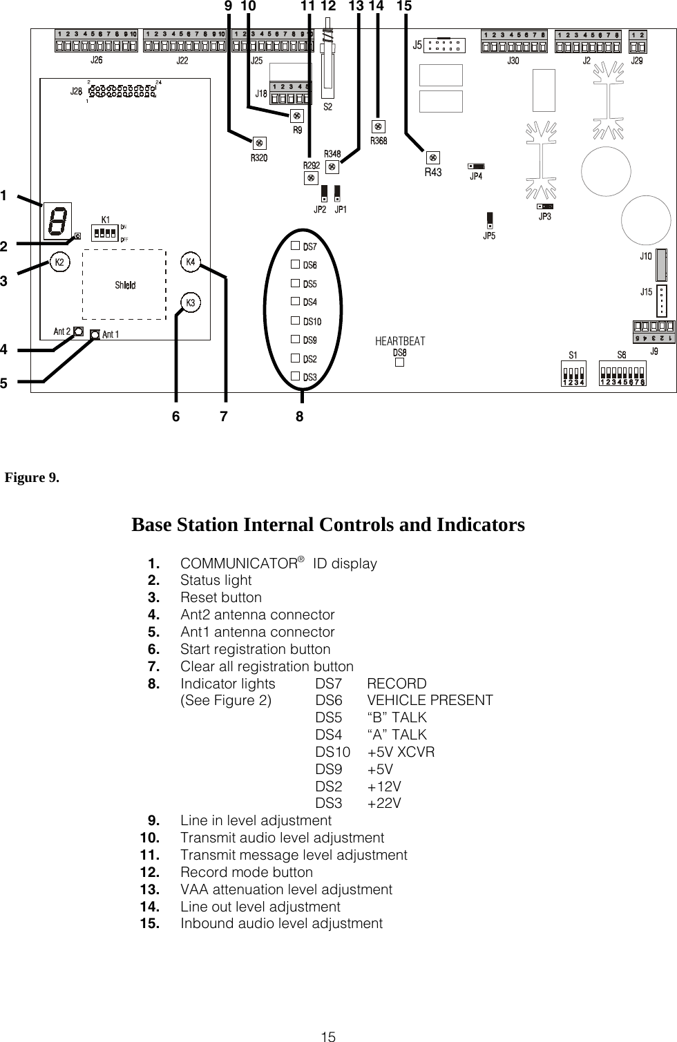
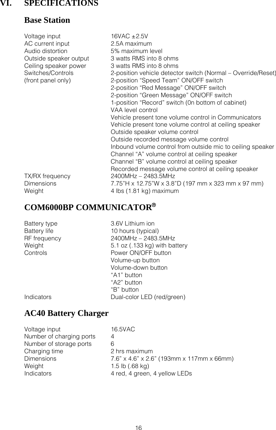
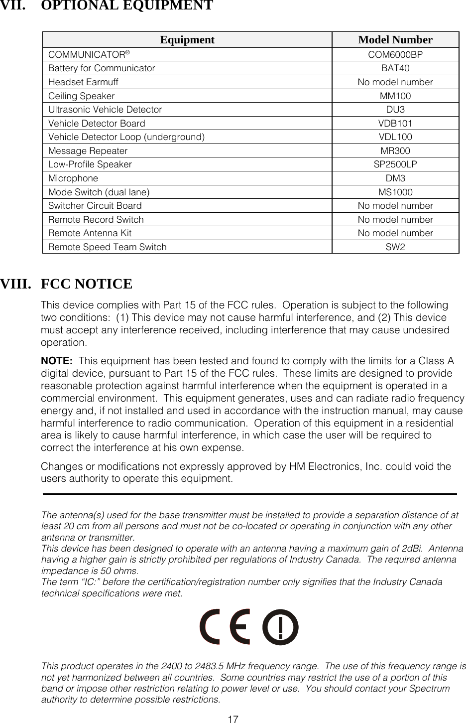
User Manual
2.
Manual
3.
installation guide
4.
antenna
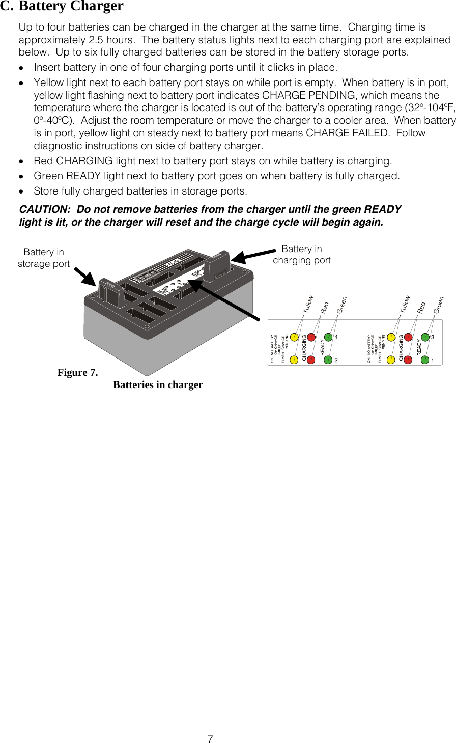
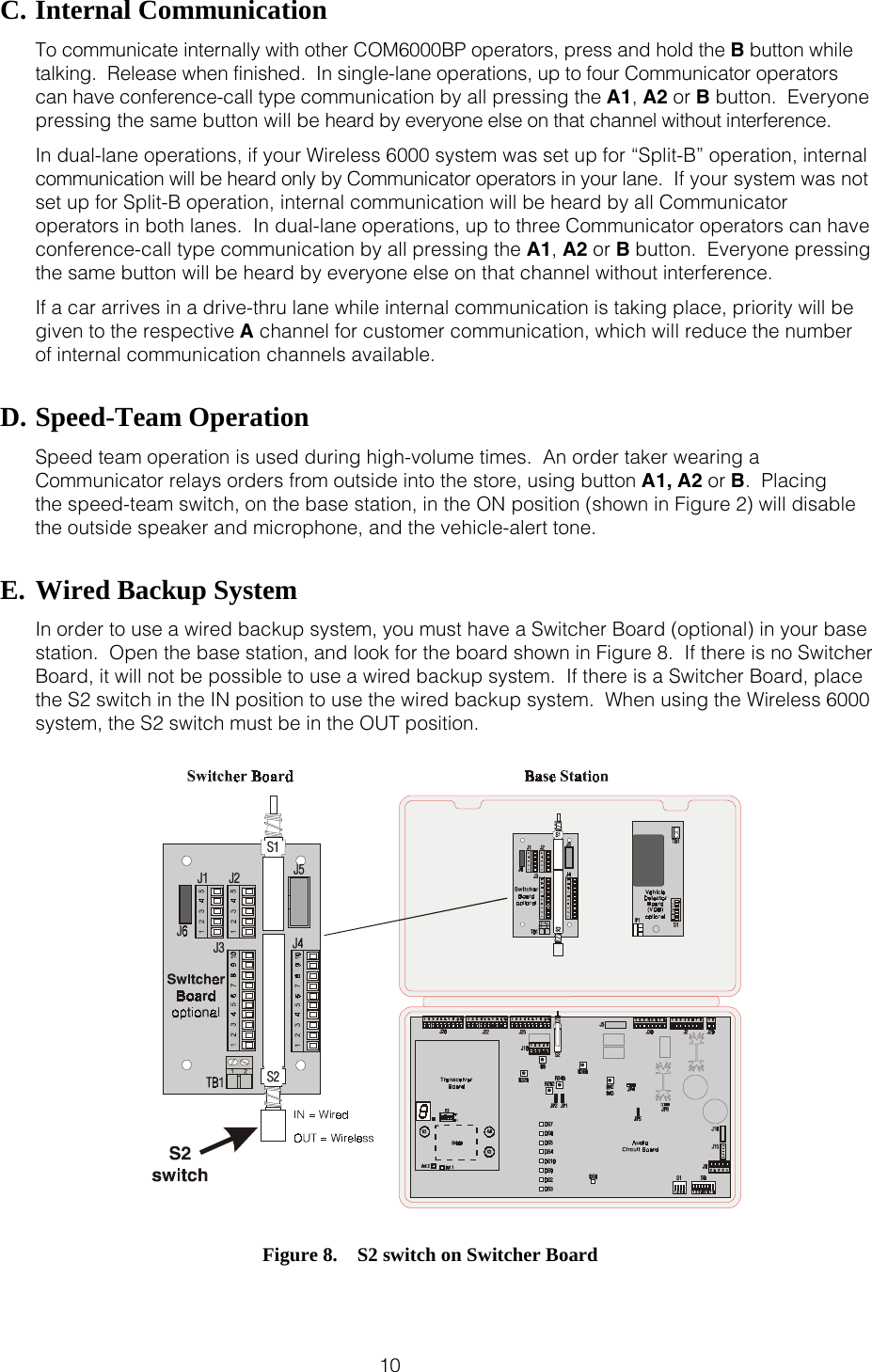
User Manual
Navigation menu
Upload a User Manual
Namespaces
Wiki Guide
HTML
PDF
Info
Views
User Manual
Discussion / Help
Navigation