HM Electronics BASE6000 BASE STATION 6000 User Manual 400519a
HM Electronics Inc BASE STATION 6000 400519a
Contents
- 1. User Manual
- 2. Manual
- 3. installation guide
- 4. antenna
User Manual

HME# 400519
Rev A 9/8/03
Wireless 6000
Wireless Drive-Thru Audio System
Operating Instructions

Table of Contents
I. GENERAL .........................................................................................................................1
II. EQUIPMENT FUNCTIONS AND USE .........................................................................1
A. Base Station .....................................................................................................................................2
B. COM6000BP COMMUNICATOR®...............................................................................................4
C. Battery Charger................................................................................................................................7
III. WIRELESS 6000 OPERATION......................................................................................8
A. Single-Lane Operation.....................................................................................................................8
B. Dual-Lane Operation .......................................................................................................................9
C. Internal Communication ................................................................................................................10
D. Speed-Team Operation ..................................................................................................................10
E. Wired Backup System ...................................................................................................................10
F. Message Repeater Operation .........................................................................................................11
IV. EQUIPMENT CARE AND CLEANING......................................................................12
A. Proper Handling.............................................................................................................................12
B. Cleaning ...................................................................................................................................12
V. IN CASE OF PROBLEMS.............................................................................................13
VI. SPECIFICATIONS.........................................................................................................16
VII. OPTIONAL EQUIPMENT............................................................................................17
VIII. FCC NOTICE..................................................................................................................17
List of Figures
Figure Title Page
1 Wireless 6000 equipment........................................................................................................1
2 Wireless 6000 Base Station with front door open...................................................................2
3 COM6000BP COMMUNICATOR® beltpac..........................................................................4
4 Wearing the Communicator headset .......................................................................................4
5 COMMUNICATOR® battery-release latch ............................................................................5
6 Registration buttons and indicators.........................................................................................6
7 Batteries in charger .................................................................................................................7
8 S2 switch on Switcher Board................................................................................................10
9 Base station internal controls and indicators.........................................................................15
The HME logo and the word COMMUNICATOR® are registered trademarks of HM Electronics, Inc.
© Copyright HM Electronics, Inc. - September 2003
1
I. GENERAL
The Wireless 6000 is a wireless audio system primarily for use at quick-service restaurants.
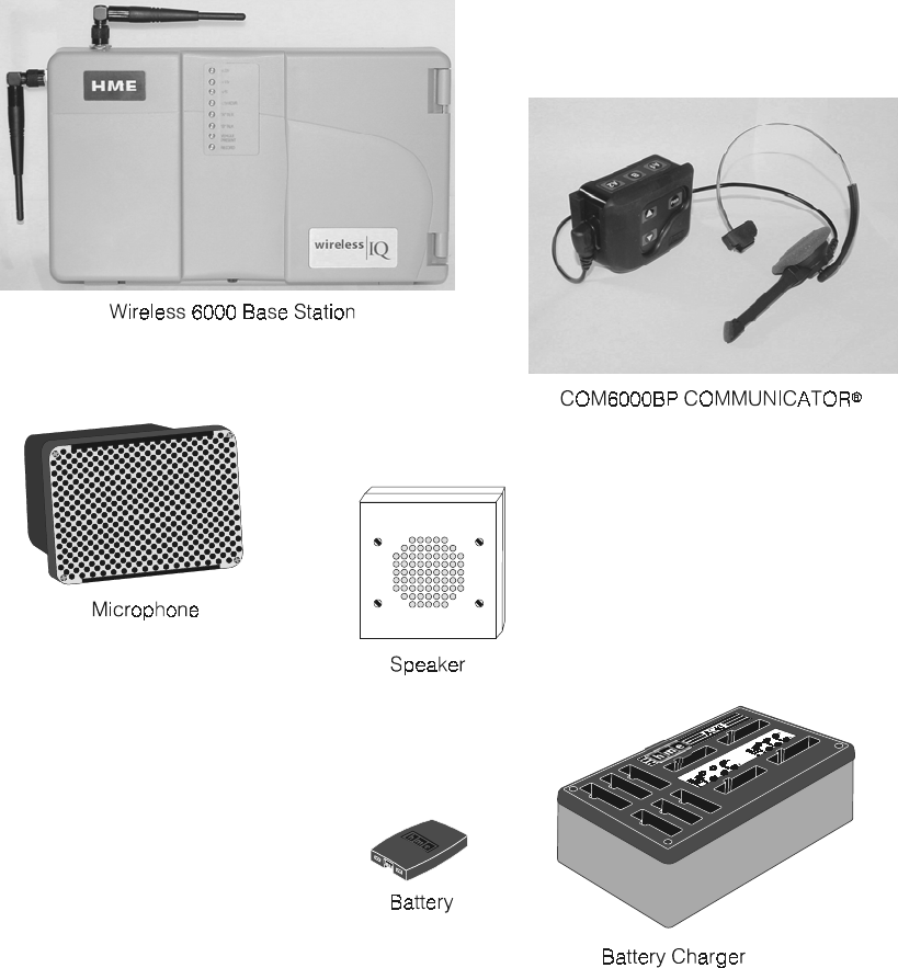
II. EQUIPMENT FUNCTIONS AND USE
Figure 1. Wireless 6000 equipment
2
A. Base Station
The base station is the electronic heart of the Wireless 6000. It contains the circuitry through
which all functions of the drive-thru audio system are channeled.
External base station features are shown in Figure 2, and described on page 3. Its internal
controls and connectors are shown in Figure 8 on page 14.
AC
B
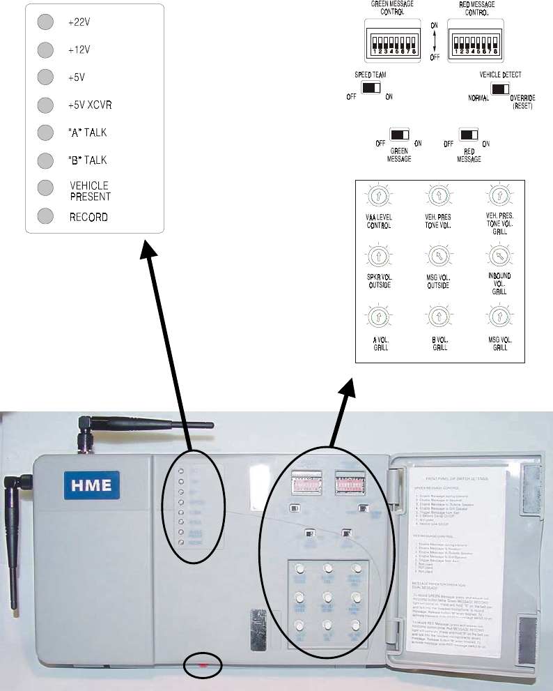
Figure 2. Wireless 6000 Base Station with front door open
3
Base Station External Features
Front — (See A on Figure 2.)
• Four power supply lights are on when the base station has AC power.
• “A” TALK light is on during channel-A transmission.
• “B” TALK light is on during channel-B transmission.
• VEHICLE PRESENT light is on when a vehicle is present in the drive-thru lane or
when the system is in vehicle-detect override.
• RECORD light is ON RED when the base station is ready to record red message for
the message repeater, and BLINKING RED while a red message is being recorded.
It is ON GREEN when the base station is ready to record green message for the
message repeater, and BLINKING GREEN while a green message is being recorded.
Bottom — (See B on Figure 2.)
• PUSH FOR RECORD MODE button must be pushed IN AND RELEASED ONCE to
prepare the base station to record red message for the message repeater, or pushed
IN AND RELEASED TWICE to record green message.
Behind Front Door — (See C on Figure 2.)
• GREEN MESSAGE and RED MESSAGE switches must be switched ON to use the
message repeater, OFF when the message repeater is not being used. Instructions
are given inside the front door.
• SPEED TEAM switch must be switched ON for speed-team operation, OFF for normal
drive-thru operation
• VEHICLE DETECTOR switch must be switched to OVERRIDE to disable the vehicle
detector. To reset the vehicle detector, switch to OVERRIDE for 5 seconds, then switch
back to NORMAL and leave for normal vehicle detection operation. If the switch is left
in the OVERRIDE position, the outside microphone will remain on continuously.
• DIP switches at the top are used to control message routing to the outside speaker, grill
speaker or COMMUNICATOR®s. DIP switch settings are shown inside the front door.
• Nine level controls are used to set the following levels:
VAA LEVEL CONTROL adjusts the volume level at which the order taker, speaking
into the headset microphone, will cause the inbound volume of the customer’s voice
to be lowered in the Communicator headset.
VEH. PRES TONE VOL. adjusts the vehicle-present tone volume in the headset.
VEH. PRES. TONE VOL. GRILL adjusts the volume of the vehicle present tone
played through the grill speaker.
SPKR VOL. OUTSIDE adjusts the outside speaker volume.
MSG VOL. OUTSIDE adjusts the volume of the outgoing message-repeater
message to the customer at the speaker post or menu board.
INBOUND VOL GRILL adjusts the volume of the inbound audio from the outside
microphone played through the grill speaker.
A VOL. GRILL adjusts the volume of channel A communication, from Communicator
operators, played through the grill speaker.
B VOL. GRILL adjusts the volume of channel B communication, from Communicator
operators, played through the grill speaker.
MSG VOL. GRILL adjusts the volume of the message-repeater message played
through the grill speaker.
4
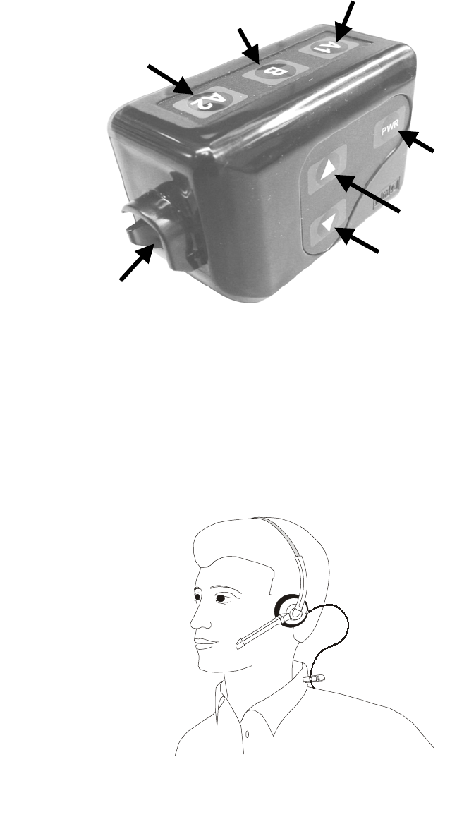
Channel “A1”
button
Channel “B”
button
Channel “A2”
button
Power
button
Volume-up
button
Volume-down
button
Headset cable
connector socket
B. COM6000BP COMMUNICATOR®
1. Features and Controls
Figure 3. COM6000BP COMMUNICATOR® beltpac
2. How to Wear the Communicator
• Wear the headset with the microphone on your right or left side next to your mouth.
• Adjust the headband for a comfortable fit.
• Clip the beltpac to your belt or waistband on either your right or left side.
• Run the headset cable up your back and clip it to the back of your shirt and collar with
clothing clips on the cable.
Figure 4. Wearing the Communicator headset
5
3. How to Use the COM6000BP COMMUNICATOR® Controls
The Communicator control buttons have a snap action. They will activate when pressed
firmly. Use your fingertips, not your fingernails, to press the buttons.
a. Power On/Off
• Power On – Press and release the PWR (power) button. A voice message in
the earpiece will say “power on,” and the beltpac number and software version,
and the red power lights next to the A1 and A2 buttons on the beltpac will go on.
After a short time, one light will go off and the other will change to green. The
voice message will then say “Lane 1 (or 2) ready.” The green light indicates the
COMMUNICATOR® is ready to use. In dual-lane operations, a green light next to A1
indicates ready on Lane 1 and a green light next to A2 indicates ready on Lane 2.
• Power Off – Press and hold the PWR button for approximately two seconds. A
voice message in the earpiece will say “power off,” and the power lights will go off.
b. Volume Up/Down
• Volume Up Adjustment – Press and release the volume-up S button. Each time
it is pressed, a beep will be heard in the earpiece as the volume increases one step.
When maximum volume is reached, “maximum” will be heard in the earpiece. If you
press and hold the volume-up button, repeating beeps will be heard as the volume
steps up to maximum. “Maximum” will be heard in the earpiece, and will be
repeated until you release the volume-up button.
• Volume Down Adjustment – Press and release the volume-down T button.
Each time it is pressed, a beep will be heard in the earpiece as the volume
decreases one step. When minimum volume is reached, a double beep will be
heard. If you press and hold the volume-down button, repeating beeps will be
heard as the volume steps down to minimum.
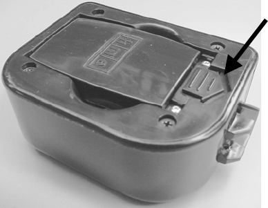
4. Battery Removal and Replacement
TO CHANGE BATTERIES: When a battery becomes weak, a voice in the earpiece will say
“Change battery.” When this happens, take the Communicator out of its pouch and remove
its battery. Slide the battery-release latch in the direction of the arrow shown in Figure 5.
Pull up on the end of the battery near the battery-release latch and lift the battery out of the
Communicator, or turn the Communicator over and catch the battery in your hand.
TO REPLACE BATTERIES: When replacing a battery in the Communicator, place the
end of the battery with the metal contacts into the battery holder on the Communicator, in
the same position as the battery you removed. Press the top of the battery carefully into
the battery holder until it snaps in place under the battery-release latch.
Battery-release
latch
Figure 5. COMMUNICATOR® battery-release latch
6
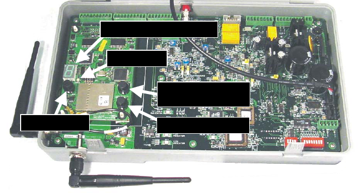
5. COMMUNICATOR® Registration
During installation of the Wireless 6000 system, each Communicator was registered for
use with a specific base station. The base station thereby recognizes all registered
Communicators when their power is on, differentiating between them and interfering
transmissions from other electronic equipment operating on similar frequencies. If a
Communicator is replaced, the new one must be registered. A maximum of 15
Communicators can be registered.
When a Communicator is replaced, the old one remains in memory. If the maximum
number of 15 is exceeded, all current registrations must be cleared, and all active
Communicators must be re-registered. To clear all current registrations, press the
“Clear All Registration” button and the “Reset” button simultaneously. Refer to Figure 6
below. Continue holding the “Clear All Registration” button after releasing the “Reset”
button, until the clear code “c” (lower case) appears on the Communicator ID display.
All active Communicators can then be registered, one at a time.
Register each Communicator as follows:
• Be certain all Communicators to be registered are powered off and the base station
power is on.
• Open the base station and press the registration button shown in Figure 6.
⎯ If no Communicators are powered on, the status light shown in Figure 6 will be blinking
red. If any Communicators are powered on, the status light will be blinking green.
⎯ After you press the registration button, the Communicator ID display will show a
small “o” for open.
• Press and hold the B button while pressing and releasing the PWR (power) button to
turn the Communicator on, then release the B button. This will cause the Communicator
to enter the registration mode.
⎯ The status light in the base station will be blinking green, and the Communicator ID
display will continue to show a small “o” for open.
⎯ The power lights next to the A1 and A2 buttons on the Communicator will be
blinking red then will change to green.
When the registration is successfully completed:
⎯ The green status light in the base station will be on steady and the Communicator
ID display, to the left of the status light, will show the ID number assigned to this
Communicator. ID numbers are assigned sequentially as 0 thru 9, A, b, C, d and E.
⎯ One of the power lights on the Communicator will remain on steady green.
Figure 6. Registration buttons and indicators
R
e
gi
strat
i
on
b
utton
S
tatus
ligh
t
C
ommun
i
cator
ID
di
sp
l
a
y
Cl
ear
All
Registration button
R
eset
b
utton
7
Battery in
storage port
Battery in
charging port
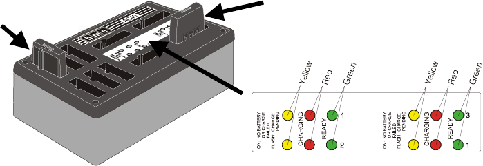
C. Battery Charger
Up to four batteries can be charged in the charger at the same time. Charging time is
approximately 2.5 hours. The battery status lights next to each charging port are explained
below. Up to six fully charged batteries can be stored in the battery storage ports.
• Insert battery in one of four charging ports until it clicks in place.
• Yellow light next to each battery port stays on while port is empty. When battery is in port,
yellow light flashing next to battery port indicates CHARGE PENDING, which means the
temperature where the charger is located is out of the battery’s operating range (32o-104oF,
0o-40oC). Adjust the room temperature or move the charger to a cooler area. When battery
is in port, yellow light on steady next to battery port means CHARGE FAILED. Follow
diagnostic instructions on side of battery charger.
• Red CHARGING light next to battery port stays on while battery is charging.
• Green READY light next to battery port goes on when battery is fully charged.
• Store fully charged batteries in storage ports.
CAUTION: Do not remove batteries from the charger until the green READY
light is lit, or the charger will reset and the charge cycle will begin again.
Figure 7.
Batteries in charger

8
III. WIRELESS 6000 OPERATION
The COM6000BP can be operated in Hands-Free (HF), Auto-Hands-Free (AHF) or Push-To-Talk (PTT)
modes. If your store does not have HF capability, the Wireless 6000 should be operated according to
section III. A. 3. below in single-lane stores, or section III. B. 3. (page 9) in dual-lane stores.
A full-duplex system supports HF, AHF and PTT operation. Communication can be transmitted and
received at the same time, as in a normal telephone conversation. In the AHF mode, transmission
and reception are activated automatically when a customer drives into the drive-thru lane. In the HF
mode, transmission and reception are activated by touching and releasing one of the A buttons on
the Communicator. In the PTT mode, one of the A buttons on the Communicator must be held while
the operator is talking to the customer. A half-duplex system only supports the PTT mode. One of
the A buttons on the Communicator must be held while the operator speaks to the customer. The
customer’s voice will not be heard while the operator is transmitting.
When a customer arrives in the drive-thru lane, you will hear a single beep in the headset for single
lane operations and for Lane 1 in dual-lane operations, or a double beep for Lane 2 in dual-lane
operations. In dual-lane operation, if you are communicating with a customer when another customer
arrives in the opposite lane, a higher pitch double beep will sound in the headset. When the first
customer leaves the speaker post, the same high pitch double beep will repeat in your headset
every four seconds until you touch the A1 or A2 button to communicate with the second customer.
NOTE: In dual-lane operations, if you have a Mode Switch and it is in the “2 OPERATORS” position,
you will only hear single beeps in your headset when customers arrive in the lane you are operating.
A. Single-Lane Operation (one base station for one speaker post)
1. Hands-Free (HF) Mode:
! With the power off, press and hold the volume-up S and B buttons while pressing and releasing the
PWR button to turn the power on in the HF mode. The Communicator will remember this setting.
! As a customer enters the drive-thru lane, you will hear an alert tone (single beep) in your headset,
and you will be able to hear the customer at the speaker post or menu board.
! Use volume-up S or down T buttons to adjust customer’s voice level in headset if necessary.
! Touch and release A1 or A2 button to speak and listen to customer.
! Touch and release A1, A2 or B button to end communication with customer.
! Touch and release A1 or A2 button if you want to speak to the customer again.
! If customer drives away from speaker post or menu board, the Communicator stops transmitting.
2. Auto Hands-Free (AHF) Mode:
NOTES: Only one Communicator operator at a time can use this feature. If a Communicator is turned
off while in the AHF mode, it will automatically be reset for its previous operating mode.
! With the power off, press and hold the volume-up S and A1 buttons while pressing and releasing the
PWR button to turn the power on in the AHF mode.
! As a customer enters the drive-thru lane, you will hear an alert tone (single beep) in your headset,
and you will be able to hear the customer at the speaker post or menu board.
! Use volume-up S or down T buttons to adjust customer’s voice level in headset if necessary.
! Speak and listen to customer without pressing any buttons.
! Touch and release A1, A2 or B button to end communication with customer.
! Touch and release A1 or A2 button if you want to speak to the customer again.
! If customer drives away from speaker post or menu board, the Communicator stops transmitting.
3. Push-To-Talk (PTT) Mode:
! With the power off, press and hold the volume-down T and B buttons while pressing and releasing the
PWR button to turn the power on in the PTT mode. The Communicator will remember this setting.
! As a customer enters the drive-thru lane, you will hear an alert tone (single beep) in your headset,
and you will be able to hear the customer at the speaker post or menu board.
! Use volume-up S or down T buttons to adjust customer’s voice level in headset if necessary.
! Touch and hold A1 or A2 button to speak to customer. Release when finished.

9
B. Dual-Lane Operation (two base stations for two speaker posts)
1. Hands-Free (HF) Mode:
! With the power off, press and hold the volume-up S and B buttons while pressing and releasing the
PWR button to turn the power on in the HF mode. The Communicator will remember this setting.
! As a customer enters a drive-thru lane, you will hear an alert tone (single beep for Lane 1,
double beep for Lane 2) in your headset, and you will be able to hear the customer at the
speaker post or menu board if that lane is selected.
! Use volume-up S or down T buttons to adjust customer’s voice level in headset if necessary.
! Touch and release A1 button for Lane 1 or A2 for Lane 2, to speak and listen to customer.
! Touch and release A1, A2 (depending on lane) or B button to end communication with customer.
! Touch and release A1 button for Lane 1 or A2 for Lane 2, to speak to the customer again.
! To change lanes, touch and release the opposite A button.
! If customer drives away from speaker post or menu board, Communicator stops transmitting.
2. Auto Hands-Free (AHF) Mode:
NOTES: Only one Communicator operator at a time, in each lane, can use this feature. If an operator
attempts to configure a second Communicator, “System busy” will be heard in his headset.
When operating in the AHF mode, changing lanes is not possible.
If a Communicator is turned off while in the AHF mode, it will automatically be reset for its
previous operating mode.
! For Lane 1 operation, with the power off, press and hold the volume-up S and A1 buttons while
pressing and releasing the PWR button to turn the power on in the AHF mode.
For Lane 2 operation, with the power off, press and hold the volume-up S and A2 buttons while
pressing and releasing the PWR button to turn the power on in the AHF mode.
! As a customer enters a drive-thru lane, you will hear an alert tone (single beep for Lane 1,
double beep for Lane 2) in your headset, and you will be able to hear the customer at the
speaker post or menu board if that lane is selected.
! Use volume-up S or down T buttons to adjust customer’s voice level in headset if necessary.
! Speak and listen to customer without pressing any buttons.
! Touch and release A1, A2 (depending on lane) or B button to end communication with customer.
! Touch and release A1 button for Lane 1 or A2 for Lane 2, to speak to the customer again.
! If customer drives away from speaker post or menu board, Communicator stops transmitting.
3. Push-To-Talk (PTT) Mode:
! With the power off, press and hold the volume-down T and B buttons while pressing and releasing the
PWR button to turn the power on in the PTT mode. The Communicator will remember this setting.
! As a customer enters a drive-thru lane, you will hear an alert tone (single beep for Lane 1,
double beep for Lane 2) in your headset, and you will be able to hear the customer at the
speaker post or menu board if that lane is selected.
! Use volume-up S or down T buttons to adjust customer’s voice level in headset if necessary.
! Touch and hold A1 button to speak to customer in Lane 1; A2 to speak to customer in Lane 2.
10
C. Internal Communication
To communicate internally with other COM6000BP operators, press and hold the B button while
talking. Release when finished. In single-lane operations, up to four Communicator operators
can have conference-call type communication by all pressing the A1, A2 or B button. Everyone
pressing the same button will be heard by everyone else on that channel without interference.
In dual-lane operations, if your Wireless 6000 system was set up for “Split-B” operation, internal
communication will be heard only by Communicator operators in your lane. If your system was not
set up for Split-B operation, internal communication will be heard by all Communicator
operators in both lanes. In dual-lane operations, up to three Communicator operators can have
conference-call type communication by all pressing the A1, A2 or B button. Everyone pressing
the same button will be heard by everyone else on that channel without interference.
If a car arrives in a drive-thru lane while internal communication is taking place, priority will be
given to the respective A channel for customer communication, which will reduce the number
of internal communication channels available.
D. Speed-Team Operation
Speed team operation is used during high-volume times. An order taker wearing a
Communicator relays orders from outside into the store, using button A1, A2 or B. Placing
the speed-team switch, on the base station, in the ON position (shown in Figure 2) will disable
the outside speaker and microphone, and the vehicle-alert tone.
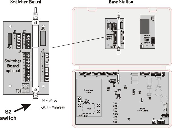
E. Wired Backup System
In order to use a wired backup system, you must have a Switcher Board (optional) in your base
station. Open the base station, and look for the board shown in Figure 8. If there is no Switcher
Board, it will not be possible to use a wired backup system. If there is a Switcher Board, place
the S2 switch in the IN position to use the wired backup system. When using the Wireless 6000
system, the S2 switch must be in the OUT position.
Figure 8. S2 switch on Switcher Board

11
F. Message Repeater Operation
ACTION RESULT
Press and release the RECORD MODE
button on the base station once.
The red MESSAGE RECORD light
on the base station will come on.
Press and hold button B on the
COMMUNICATOR® and talk into the
headset microphone to record a
message (up to 8 seconds).
The MESSAGE RECORD light on the
base station will begin blinking.
To record
Message #1
Release button B. The record function will stop and the
MESSAGE RECORD light will go off.
Press and release the RECORD MODE
button on the base station twice.
The green MESSAGE RECORD light
on the base station will come on.
Press and hold button B on the
Communicator and talk into the headset
microphone to record a message
(up to 8 seconds).
The MESSAGE RECORD light on the
base station will begin blinking.
To record
Message #2
Release button B. The record function will stop and the
MESSAGE RECORD light will go off.
Locate the ”RED MESSAGE” and “GREEN MESSAGE” slide switches, and the “RED MESSAGE
CONTROL” and “GREEN MESSAGE CONTROL” DIP switches inside the front door of the base
station for the following settings.
RED MESSAGE switch in the ON position enables the “RED MESSAGE” to be played.
A playing message can be cancelled by pressing Communicator button A.
RED MESSAGE CONTROL
Switch 1 enables inbound audio from speaker post to be heard while message is playing.
Switch 2 enables message to be played to all Communicators.
Switch 3 enables message to be played on the outside speaker.
Switch 4 enables message to be played on the ceiling speaker.
Switch 5 causes message to be triggered by an external alert signal.
Switches 6, 7 and 8 not used
GREEN MESSAGE switch in the ON position enables the “GREEN MESSAGE” to be played.
A playing message can be cancelled by pressing Communicator button A.
GREEN MESSAGE CONTROL
Switch 1 enables inbound audio from speaker post to be heard while message is playing.
Switch 2 enables message to be played to all Communicators.
Switch 3 enables message to be played on the outside speaker.
Switch 4 enables message to be played on the ceiling speaker.
Switch 5 causes message to be triggered by an external alert signal.
Switch 6 causes a 3 second delay before message is played.
Switch 7 not used
Switch 8 allows selection of a single-beep alert tone or two short beeps.
If both RED MESSAGE and GREEN MESSAGE switches are in the ON position, and are
selected for the same output, Red and Green Messages will be played alternately.
After a new message has been recorded or after the base station has lost and regained
power, any message to the outside speaker will always be heard in the Communicator
headset the first three times it plays, whether Switch 1 is in the ON or OFF position.
12
IV. EQUIPMENT CARE AND CLEANING
A. Proper Handling
• When adjusting microphone position, hold boom at base, not at microphone end.
• Carry headset by headband, not by earpiece, and never by microphone boom.
• Use both hands to put headset on or take it off.
B. Cleaning
1. COM6000BP COMMUNICATOR®
• Remove batteries from Communicators.
• Clean batteries and Communicators with damp sponge sprayed with household
cleaner. Squeeze excess liquid out of sponge before using it.
• Clean metal battery contacts on batteries and Communicators as follows. Wet
tip of swab with alcohol and squeeze excess alcohol from it. Wipe each contact
with swab and be certain all contacts are dry before reinstalling batteries.
• Foam muffs on headset earpieces can easily be replaced for sanitary purposes.
To order extra foam muffs, call your local HME sales representative.
2. Battery Charger
Avoid splashing water or grease on the battery charger.
Clean the battery charger monthly as follows.
CAUTION: Always unplug the battery charger before cleaning it.
• Remove all batteries from the battery charger.
• Clean the battery charger case with a damp sponge. Wet the sponge and wring
it out so it is damp, not dripping wet. Spray household cleaner on the sponge
(NOT DIRECTLY ON THE EQUIPMENT). Clean the battery charger with the
sponge and dry it thoroughly.
• Wet the tip of a cotton swab with rubbing alcohol and squeeze the excess
alcohol from the swab. Wipe the metal contacts inside each battery port with
the damp swab. Allow the contacts to dry before placing batteries in the ports.

13
V. IN CASE OF PROBLEMS
PROBLEM PROBABLE CAUSE SOLUTION
Power may be off at base station. Check circuit breaker for building.
Power supply in base station may
not be working.
Check power supply indicator lights
on base station. If no light is lit,
be certain AC power adapter is
plugged into AC electrical outlet, and
is connected to J29 on base station
audio circuit board.
Communicator power may not be on. Press Power ON/OFF button on
Communicator. Be certain power
light goes on and switches from red
to green.
Volume may not be set correctly. Adjust volume with Volume-up and
down buttons.
Battery may be low or defective. Check Communicator Power light. If
not lit, replace battery.
No sound is heard in
COMMUNICATOR®
headset when you
press button A and
speak into
microphone.
Headset may be defective. Use another headset. Call HME. *
Communicator power may not be
on.
Press Power ON/OFF button on
Communicator. Be certain power
light goes on and switches from red
to green.
Battery may be low or defective. Check Power light. If not lit, replace
battery.
Channel A or B is not
working.
“A” Talk or “B” Talk light on base
station does not light when button A
or B on Communicator is pressed.
Use another Communicator.
Call HME. *
Outbound sound is
too low.
Outbound volume may be set too
low for environment.
Turn outside speaker volume control,
on front panel of base station,
clockwise until volume is satisfactory.
System may be set for speed-team
operation.
Be certain SPEED TEAM button on
base station is in OFF position.
There may be loose wires on
outside speaker or base station
circuit board.
Check VEHICLE PRESENT light on
base station. Check outside speaker
wire connections in base station and
at outside speaker.
No outbound sound;
Customer cannot
hear anything.
Speaker or base station may be
defective.
Call HME. *
System may be set for speed-team
operation.
Be certain SPEED TEAM button on
base station is in OFF position.
Customer cannot be
heard in push-to-talk
(PTT) operation. Base station may be set for wrong
drive-thru mode (full or half-duplex).
Check S6 DIP switch #1 at bottom of
base station audio circuit board. It
should be ON for full-duplex, OFF for
half-duplex operation.
Transmitter antenna connectors on
base station transceiver circuit
board may be loose or damaged.
Be certain antennas are screwed
securely onto base station. Check
transmitter antenna cable connection
at ANT1 and ANT2 near lower-left
corner of transceiver circuit board.
Pull and remove each connector
plug, and check to be certain pin
inside it is not bent. If not, call HME.
*
Only intermittent
voice can be heard in
headsets.
Circuit board may be defective. Call HME. *

14
PROBLEM PROBABLE CAUSE SOLUTION
Circuit board may be defective. Check to see if status lights on base
station are lit. Call HME. *
Personnel hear
customers in ceiling
speaker or headsets,
but cannot hear
each other.
Beltpac may be defective. Use another beltpac. Call HME. *
Power interruption may have
caused vehicle detection circuit to
be out of balance.
When no vehicle is in the drive-thru
lane, move the vehicle detector
override switch on the base station
to the RESET position, then back to
the NORMAL position.
System may be set for speed-team
operation.
Be certain SPEED TEAM switch on
base station is in OFF position.
No tone or sound is
heard in ceiling
speaker or headsets
when vehicle enters
drive-thru lane.
Connector may be loose, or S6 DIP
switch #8 is not set to ON.
Check all connectors in base
station, and be certain S6 #8 is set
to ON. Call HME. *
There may be loose wires on base
station circuit board.
Check all connections on base
station circuit boards.
System may be set for speed-team
operation.
Be certain SPEED TEAM switch on
base station is in OFF position.
Personnel cannot
hear customers in
ceiling speaker or
headsets.
Outside speaker, audio circuit
board or vehicle detector board
may have failed.
Call HME. *
Battery may be low. Replace battery.
Headset has
intermittent sound. Headset may be defective. Use another headset. Call HME. *
VEHICLE DETECT switch on base
station may be in the OVERRIDE
position.
Be certain switch is in the NORMAL
position.
There is still sound in
headset after all
customers have
been served. Vehicle detector may be locked up. Slide VEHICLE DETECT switch back
and forth slowly twice.
Battery charger is
not working.
Charger may not be plugged in. Be certain charger is plugged in.
If it still is not working, call HME. *
Red or Green
message will not
play.
Switch not on. Be certain respective Red or Green
message repeater switch on base
station is in the ON position, and
routing switches are set.
Registration of
COMMUNICATOR®
failed. “Registration
failed” message
heard in headset.
Lights stay red.
Base station power not on.
Communicator B button not
pushed when powering up.
Registration button not pushed.
Repeat registration procedure on
page 6.
Call HME. *
* For assistance, call HME at 1-800-848-4468, or Fax 858-552-0172.
In the event of an electrical power outage –
such as from a lightning storm or power generator failure, if you experience problems
with your HME equipment after the electricity comes on again, unplug the AC power
adapters from their electrical outlets and wait 15 seconds, then plug them back in.
2400MHz cordless telephone interference –
If there is a 2400MHz cordless telephone nearby, interference may occur. However,
because the Wireless 6000 is a frequency-hopping system, this problem is unlikely.
If it does occur, changing frequencies on the telephone may alleviate the problem.
If not, move the phone as far as practical from the base station, or use another type
phone. Call HME Customer Support at 1-800-848-4468 if assistance is required.
15
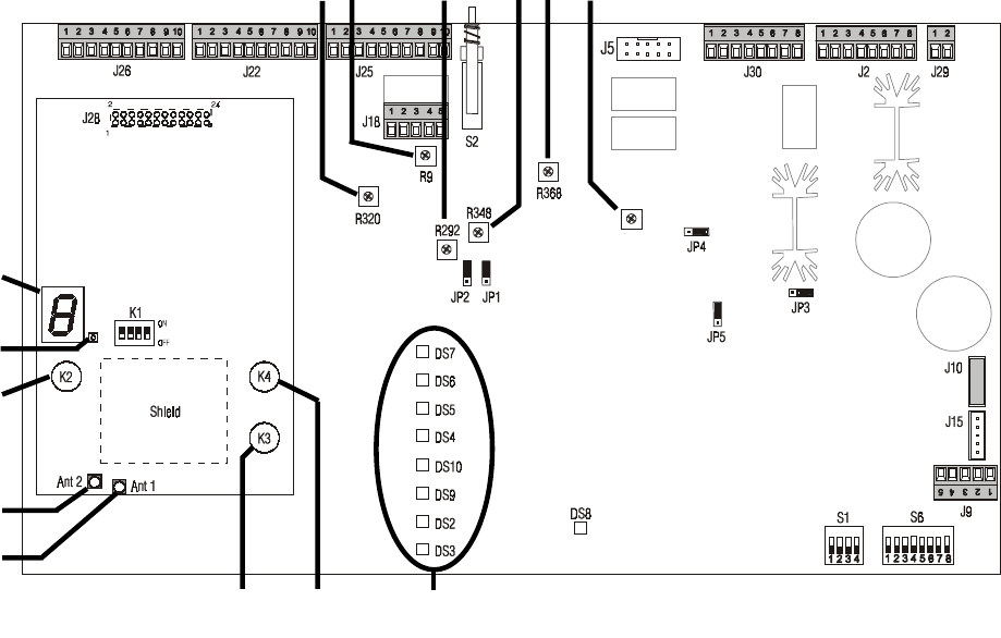
Figure 9.
Base Station Internal Controls and Indicators
1. COMMUNICATOR® ID display
2. Status light
3. Reset button
4. Ant2 antenna connector
5. Ant1 antenna connector
6. Start registration button
7. Clear all registration button
8. Indicator lights DS7 RECORD
(See Figure 2) DS6 VEHICLE PRESENT
DS5 “B” TALK
DS4 “A” TALK
DS10 +5V XCVR
DS9 +5V
DS2 +12V
DS3 +22V
9. Line in level adjustment
10. Transmit audio level adjustment
11. Transmit message level adjustment
12. Record mode button
13. VAA attenuation level adjustment
14. Line out level adjustment
15. Inbound audio level adjustment
R43
6 7 8
9 10 11 12 13 14 15
1
2
3
4
5
HEARTBEAT
16
VI. SPECIFICATIONS
Base Station
Voltage input 16VAC ±2.5V
AC current input 2.5A maximum
Audio distortion 5% maximum level
Outside speaker output 3 watts RMS into 8 ohms
Ceiling speaker power 3 watts RMS into 8 ohms
Switches/Controls 2-position vehicle detector switch (Normal — Override/Reset)
(front panel only) 2-position “Speed Team” ON/OFF switch
2-position “Red Message” ON/OFF switch
2-position “Green Message” ON/OFF switch
1-position “Record” switch (0n bottom of cabinet)
VAA level control
Vehicle present tone volume control in Communicators
Vehicle present tone volume control at ceiling speaker
Outside speaker volume control
Outside recorded message volume control
Inbound volume control from outside mic to ceiling speaker
Channel “A” volume control at ceiling speaker
Channel “B” volume control at ceiling speaker
Recorded message volume control at ceiling speaker
TX/RX frequency 2400MHz — 2483.5MHz
Dimensions 7.75”H x 12.75”W x 3.8”D (197 mm x 323 mm x 97 mm)
Weight 4 lbs (1.81 kg) maximum
COM6000BP COMMUNICATOR®
Battery type 3.6V Lithium ion
Battery life 10 hours (typical)
RF frequency 2400MHz — 2483.5MHz
Weight 5.1 oz (.133 kg) with battery
Controls Power ON/OFF button
Volume-up button
Volume-down button
“A1” button
“A2” button
“B” button
Indicators Dual-color LED (red/green)
AC40 Battery Charger
Voltage input 16.5VAC
Number of charging ports 4
Number of storage ports 6
Charging time 2 hrs maximum
Dimensions 7.6” x 4.6” x 2.6” (193mm x 117mm x 66mm)
Weight 1.5 lb (.68 kg)
Indicators 4 red, 4 green, 4 yellow LEDs

17
VII. OPTIONAL EQUIPMENT
Equipment Model Number
COMMUNICATOR® COM6000BP
Battery for Communicator BAT40
Headset Earmuff No model number
Ceiling Speaker MM100
Ultrasonic Vehicle Detector DU3
Vehicle Detector Board VDB101
Vehicle Detector Loop (underground) VDL100
Message Repeater MR300
Low-Profile Speaker SP2500LP
Microphone DM3
Mode Switch (dual lane) MS1000
Switcher Circuit Board No model number
Remote Record Switch No model number
Remote Antenna Kit No model number
Remote Speed Team Switch SW2
VIII. FCC NOTICE
This device complies with Part 15 of the FCC rules. Operation is subject to the following
two conditions: (1) This device may not cause harmful interference, and (2) This device
must accept any interference received, including interference that may cause undesired
operation.
NOTE: This equipment has been tested and found to comply with the limits for a Class A
digital device, pursuant to Part 15 of the FCC rules. These limits are designed to provide
reasonable protection against harmful interference when the equipment is operated in a
commercial environment. This equipment generates, uses and can radiate radio frequency
energy and, if not installed and used in accordance with the instruction manual, may cause
harmful interference to radio communication. Operation of this equipment in a residential
area is likely to cause harmful interference, in which case the user will be required to
correct the interference at his own expense.
Changes or modifications not expressly approved by HM Electronics, Inc. could void the
users authority to operate this equipment.
The antenna(s) used for the base transmitter must be installed to provide a separation distance of at
least 20 cm from all persons and must not be co-located or operating in conjunction with any other
antenna or transmitter.
This device has been designed to operate with an antenna having a maximum gain of 2dBi. Antenna
having a higher gain is strictly prohibited per regulations of Industry Canada. The required antenna
impedance is 50 ohms.
The term “IC:” before the certification/registration number only signifies that the Industry Canada
technical specifications were met.
This product operates in the 2400 to 2483.5 MHz frequency range. The use of this frequency range is
not yet harmonized between all countries. Some countries may restrict the use of a portion of this
band or impose other restriction relating to power level or use. You should contact your Spectrum
authority to determine possible restrictions.