HM Electronics BASE6000 EC20 - Extended Coverage Antenna Kit User Manual 400G633 1st
HM Electronics Inc EC20 - Extended Coverage Antenna Kit 400G633 1st
Contents
- 1. User Manual
- 2. Manual
- 3. installation guide
- 4. antenna
installation guide
HM ELECTRONICS, INC. 14110 Stowe Drive, Poway, CA 92064 USA • Phone: 1-800-848-4468 Fax: (858) 552-0172
HME# 400G633
Rev A
4
/
1
/0
9
EC20
Extended Coverage Antenna Kit
INSTALLATION INSTRUCTIONS
The EC20 is a directional antenna, primarily designed for extended outdoor coverage during speed-team
operations. It enables team members wearing HME COMMUNICATOR®s to greet customers at a greater
distance from the building, with uninterrupted transmission and reception. It can also be used indoors, in
stores where coverage is exceptionally difficult with standard, base station antennas.
These instructions are for typical outdoor installation of the EC20, which requires walk testing the antenna
coverage area to determine the best location for the antenna, mounting the antenna on the building, running
the coaxial cable from the base station to the antenna, connecting the cable to the antenna, lightning
arrestor, antenna adaptor cable and base station. Installation of the EC20 should only be done by an
HME-authorized installer. The installation should take approximately 2 hours.
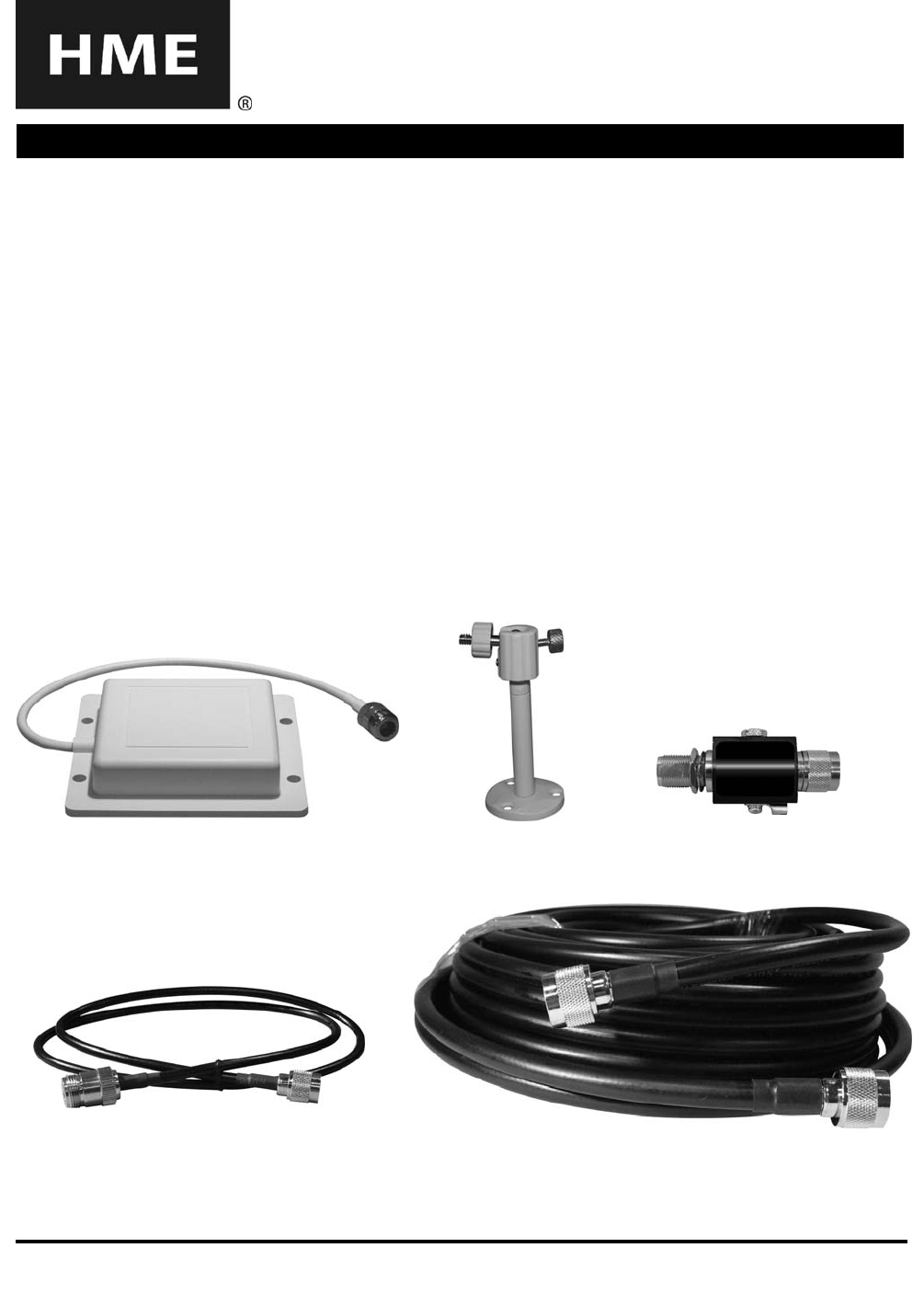
Equipment Provided
• EC20 Antenna
• Antenna mounting bracket with hardware
• Lightning arrestor with mounting bracket
• Coaxial Cable, 100 foot (30.48 meters)
• Antenna adaptor cable, 3 foot ( .91 meter)
Tools/Equipment Needed
• Phillips (cross-point) screwdriver, size #2
• Standard (slotted) screwdriver, ⅛ inch (3.2 mm)
• Power drill and drill-bit set
• Fish tape, 100 foot (30 meters)
• Wire, 18 gauge, for grounding lightning arrestor
• Ladder to reach outside antenna-mounting location
Antenna mounting
bracket
Coaxial cable, 100 ft (30.48 meters) Antenna adaptor cable, 3 ft (.91 meter)
Figure 1. Equipment provided in EC20 Extended Coverage Antenna Kit
Lightning arrestor
EC20 Antenna
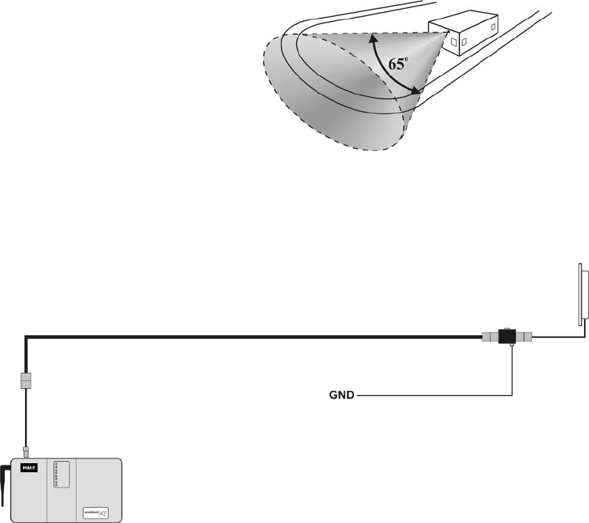
2
Figure 2. Typical EC20 Antenna coverage area
1. INSTALLATION
1.1 Determine Location
Determine the best location for mounting the EC20 Antenna, with the following considerations.
• Coverage area —
The optimum coverage area spans
out at 65 degrees in a cone shape,
extending outward in front of the
antenna approximately 130 feet
(39.62 meters). The mounting
bracket provided with the antenna
will allow it to be pivoted and locked
into the best position for the
required coverage area.
• Cable routing —
The 100 foot (30.48 meter) coaxial cable must be able to be routed from the base station,
through walls and ceiling as needed, to reach the antenna. Note that the coaxial cable is
thick and relatively stiff, making it difficult to route around corners and through tight openings.
• Esthetics —
Some stores restrict the location of equipment mounted on the outside of stores, with
regard to distance from signage or visibility to customers, for esthetic reasons.
• Walk test —
To determine the best location for mounting it, you must do a walk test before
permanently mounting the EC20 Antenna. Remove power from the HME base station
and remove one of the base station antennas. Temporarily connect the enclosed antenna
adapter cable where you removed the base station antenna, and then connect the coaxial
cable to the adapter cable as shown in Figure 3. Route the coaxial cable to the area where
you would like to mount the EC20 Antenna, and connect the lightning arrestor and antenna
to the cable connector. Place the antenna temporarily in a position with its front surface
pointing to the area where its extended coverage is needed. Return power to the base
station. With two people using COMMUNICATOR®s (with fully charged batteries) and
pressing button B to communicate with each other, check transmission and reception
around the menu board and throughout the area where speed-team operators will walk.
If necessary, move the antenna and repeat the walk test until you find the location where
the best transmission and reception occur. You can now permanently mount the EC20
Antenna in accordance with the following instructions.
HME
base station
Figure 3. Diagram of EC20 cable routing and connections
Ground wire
(not provided)
Coaxial cable
100 ft.
(
30.48 meters
)
Antenna
adapter cable
3 ft. (.91 meter)
Lightning
arrestor
EC20
Antenna
3
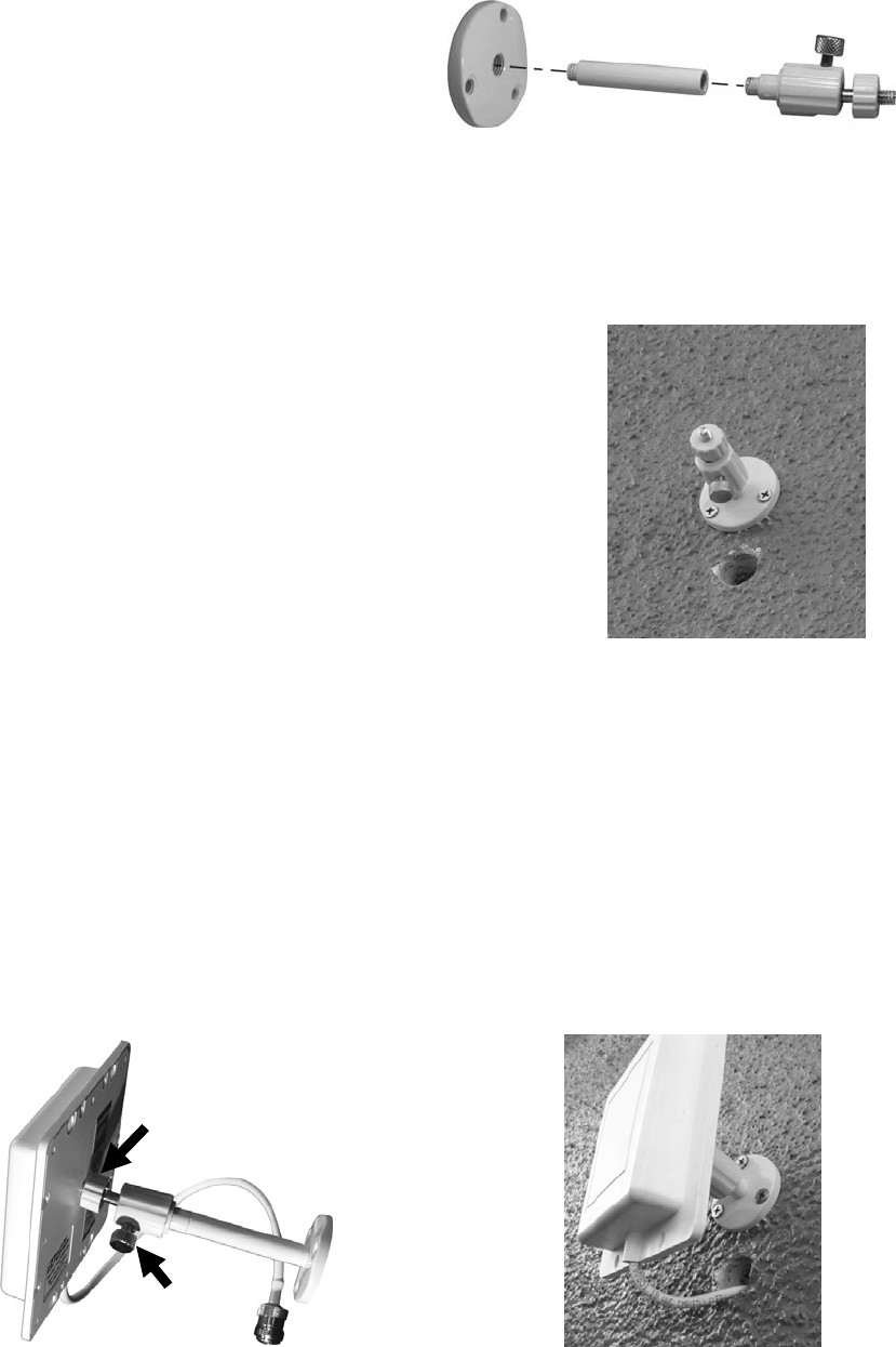
1.2 Mount Antenna
1.2.1 Assemble Antenna Bracket
The antenna bracket can be used without its
extension rod to mount the antenna about
2.5 inches (64 mm) from the wall or, with
the extension rod added, 5 inches (127 mm)
from the wall. Determine which will be best
for your installation and assemble the
bracket as needed. Refer to Figure 4.
NOTE: If the antenna will be mounted on the side of the building, where it may need to be
pivoted to nearly a 90 degree angle from the mounting surface, it will probably require using
the extension rod on the bracket.
1.2.2 Mount Antenna Bracket on Wall
• Hold the base of the antenna bracket against the wall at
the mounting location, and mark the wall through the
three screw holes in the base.
• Put the bracket aside and drill a 3/16 inch (4.76 mm)
hole in the wall at each of the marked spots.
• Insert one of the enclosed screw anchors all the way
into each of the drilled holes.
• Place the base of the bracket with its three screw holes
over the anchors and insert the enclosed screws
through the holes, screwing them all the way into the
anchors to hold the bracket securely in place.
• Drill a ¾ inch (19 mm) hole in the wall, centered
approximately 2 inches (50.8 mm) below the base of
the bracket, where the antenna cable will be inserted.
1.2.3 Attach Antenna to Bracket
• Screw the center hole on the back of the antenna onto the threaded tip of the bracket,
as shown in Figure 6.
• Pivot the antenna to the desired position, so the flat surface on the front of the antenna is
pointing toward the area where extended coverage is most needed, and lock it in place by
turning the lock knob clockwise to tighten it.
• Insert the antenna cable connector and cable through the hole in the wall below the
bracket, as shown in Figure 7.
• Be sure enough cable is left outside the hole for the antenna to be pivoted freely, and so
any rain water on the cable will drip off it rather than running down the cable toward the
hole, and fill the hole around the cable with weatherproofing sealant.
Figure 4. Antenna bracket assembly
Extension rod
Figure 5. Antenna bracket
mounted on wall with hole
below it for antenna cable
Figure 7. Antenna cable
inserted through hole in wall
Bracket
screwed into
center hole on
back of antenna
Figure 6. Antenna attached to bracket
(
shown here with extension rod
)
Lock knob
4
1.3 Run Cable
Inside the store, run the enclosed 100 foot (30.48 meter) coaxial cable from the base station of
the HME audio system, through walls and ceiling as needed, to where the antenna cable
comes through the wall.
1.4 Make Connections
• Remove the antenna from the top of the HME base station, and connect the EC20 antenna
adapter cable in its place. One end of the cable has a connector that fits the connector on
the base station, and the other end has a larger connector.
NOTE: For optimum antenna coverage, the EC20 adapter cable should be connected directly
to the base station connector, not to a splitter.
• Connect the other end of the antenna adapter cable to the coaxial cable.
• Go to where the EC20 antenna cable comes through the outside wall into the building.
Connect the enclosed lightning arrestor to the EC20 antenna cable, and then connect the
coaxial cable connector to the other side of the lightning arrestor.
• Attach a grounding wire to the ground connector screw on the lightning arrestor, and run
the other end of the wire to the nearest grounding point and connect it there.
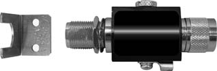
• Using the mounting bracket enclosed with the lightning arrestor to mount the lightning
arrestor on the wall is recommended. This will act as a strain relief to prevent pulling on the
antenna cable. Use two screws (not provided) to mount the bracket on the wall before
attaching the lightning arrestor to it. Tighten the bolt on the lightning arrestor to secure it to
the bracket.
2. TROUBLESHOOTING
If any dropouts occur in the HME audio system’s transmission and reception, try loosening the
lock knob on the EC20 Antenna and repositioning it, and locking it in place again. Then do
another walk test for transmission and reception with the antenna in its new position. If
necessary, continue readjusting the antenna position and repeating the walk test until the
dropouts no longer occur.
3. SPECIFICATIONS
Electrical
Frequency 2400-2500 MHz
Gain 8 dBic
Polarization Right hand circular
Beam width 65 degrees, vertical and horizontal
Impedance 50 Ohm
Max. input power 25 Watts
VSWR < 1.5:1 average
Lightning protection DC short
Mechanical
Weight 0.4 lbs. (.18 Kg)
Dimensions 4.5 x 4.5 x .9 inches (114 x 114 x 23 mm)
Operating temperature -40°F to 185°F (-40°C to 85°C)
Mounting Four ¼ inch (6.3 mm) screw holes
Figure 8. Lightning arrestor and bracket
5
FCC NOTICE
The use of all radio equipment is subject to radio regulations in each country. It is the responsibility of the
purchaser/installer/operator to insure that only approved equipment is installed/used. For the ISM band equipment
(equipment that generates RF energy for industrial, scientific or medical purposes) manufactured, sold/or used in the
USA, FCC Title 47, Part 15 governs its sale, lease, use and manufacture, and prohibits the same unless such equipment
is used in the FCC-certified system configuration with which it is authorized. This equipment is intended for use in
industrial or commercial environments only, and is not intended for use by the general public.
According to FCC rules, this equipment requires professional installation. This equipment must be purchased only
from HME authorized dealers, and its installation must be done by HME certified professionals. The installation of
this equipment must be done appropriately to ensure that its placement and setup meets the needs of individual
customers and locations. To ensure system components are installed in compliance with applicable building codes,
installation of this equipment may require a trained electrician.
Waste Electrical and Electronic Equipment (WEEE)
The European Union (EU) WEEE Directive (2002/96/EC) places an obligation on producers (manufacturers,
distributors and/or retailers) to take-back electronic products at the end of their useful life. The WEEE Directive
covers most HME products being sold into the EU as of August 13, 2005. Manufacturers, distributors and retailers are
obliged to finance the costs of recovery from municipal collection points, reuse, and recycling of specified percentages
per the WEEE requirements.
Instructions for Disposal of WEEE by Users in the European Union
The symbol shown below is on the product or on its packaging which indicates that this product was put on the market
after August 13, 2005 and must not be disposed of with other waste. Instead, it is the user’s responsibility to dispose
of the user’s waste equipment by handing it over to a designated collection point for the recycling of WEEE. The
separate collection and recycling of waste equipment at the time of disposal will help to conserve natural resources and
ensure that it is recycled in a manner that protects human health and the environment. For more information about
where you can drop off your waste equipment for recycling, please contact your local authority, your household waste
disposal service or the seller from whom you purchased the product.
The antenna(s) used for the base transmitter must be installed where there is a separation distance of at least 7.87 inches
(20 cm) from all persons, and must not be near or operating in conjunction with any other antenna or transmitter.