Honeywell KSN770 Aviation Communications Transceiver User Manual 006 10716 0000
Honeywell International Inc. Aviation Communications Transceiver 006 10716 0000
UserManual.wiki
>
Honeywell
>
KSN770 User Manual
User Manual
Navigation menu
Upload a User Manual
Namespaces
Wiki Guide
HTML
PDF
Info
Views
User Manual
Discussion / Help
Navigation


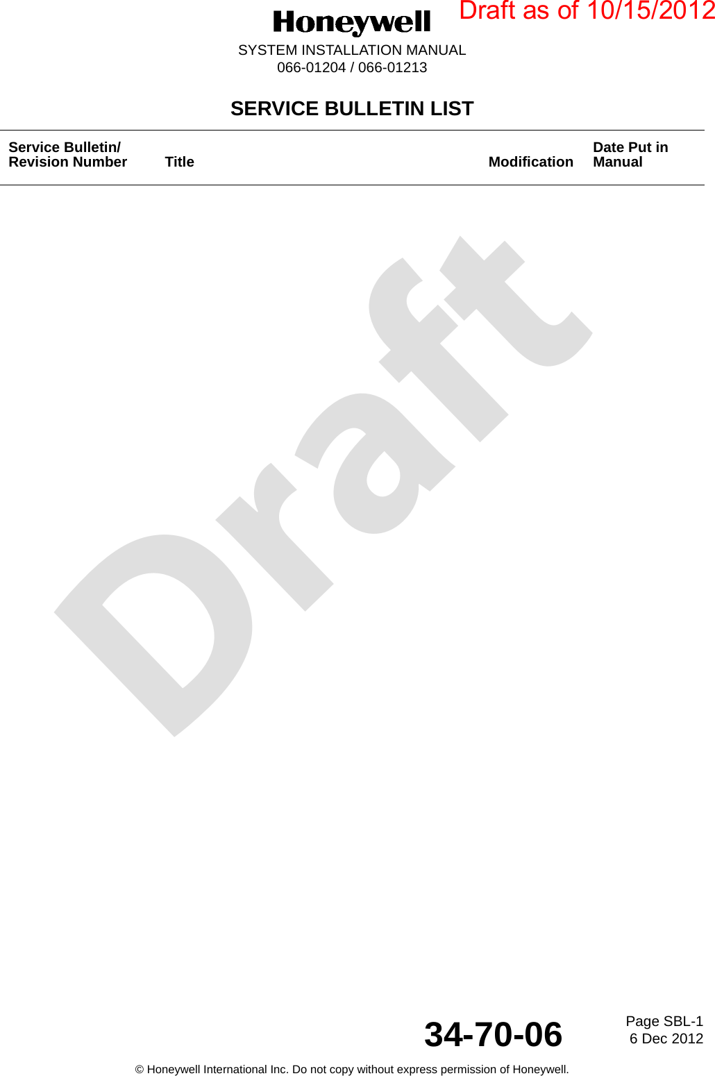


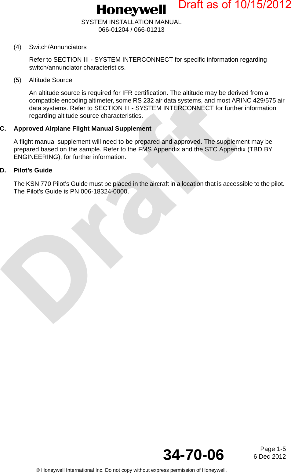


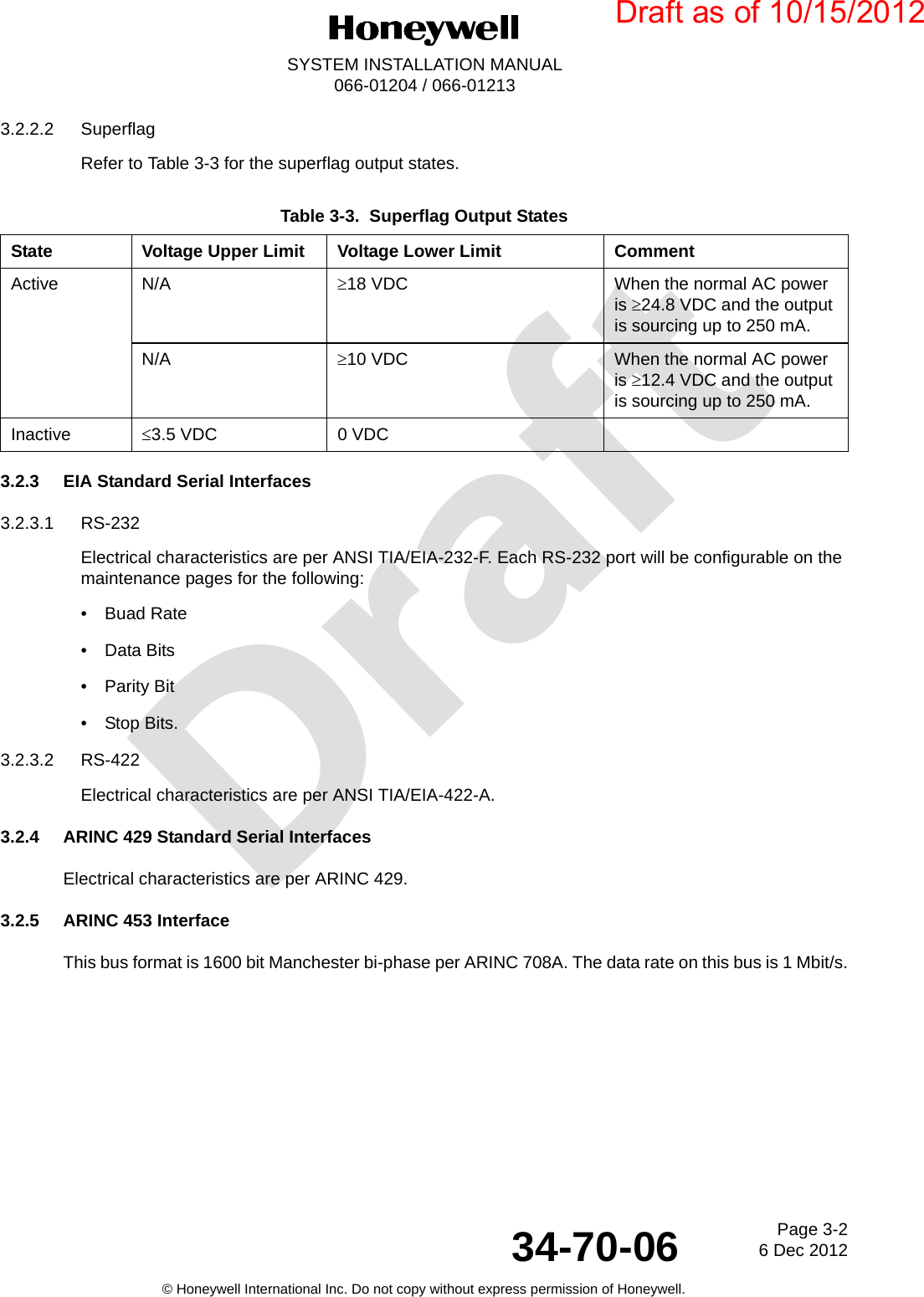
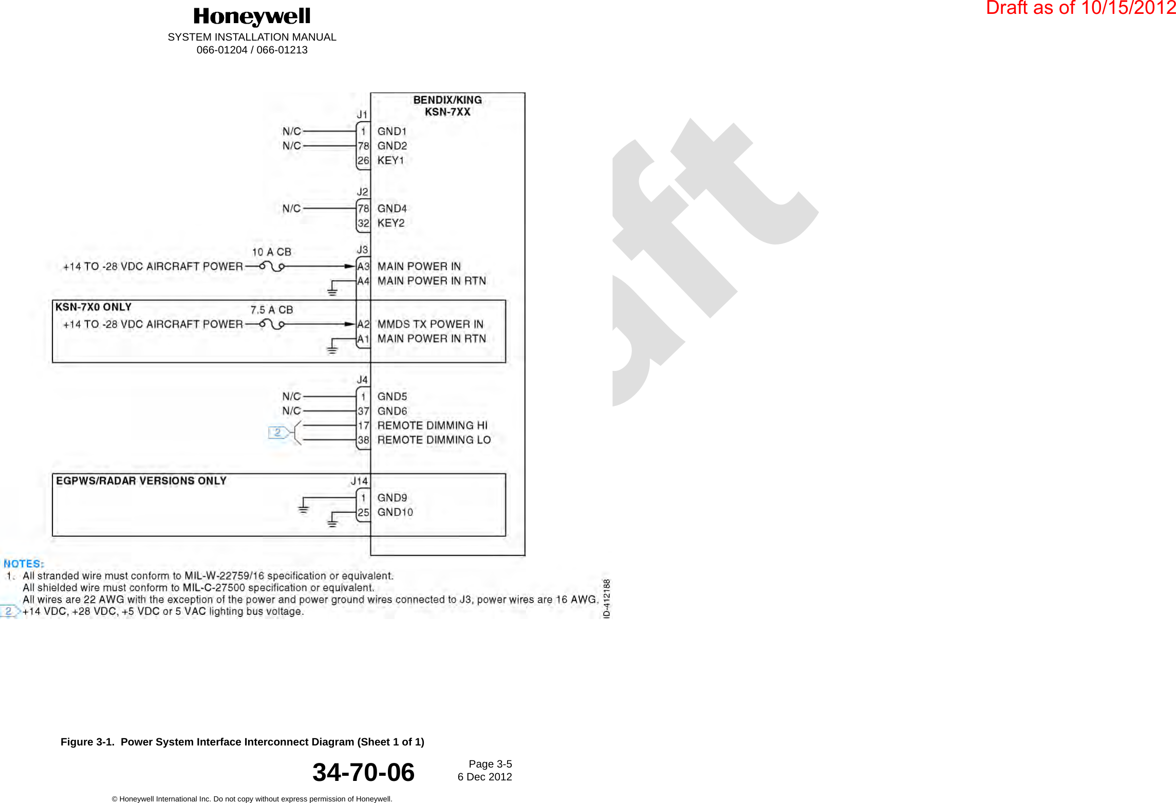
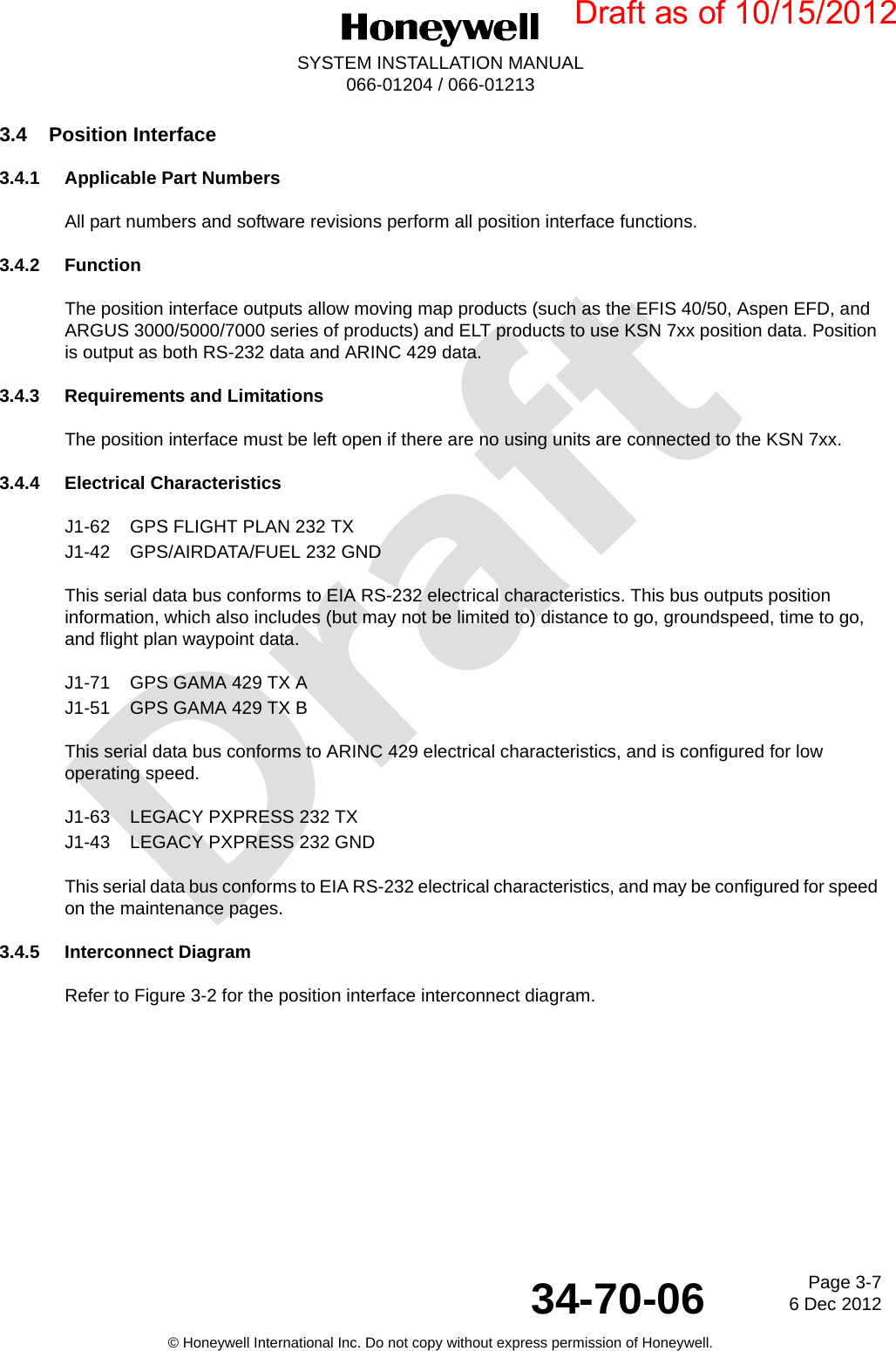
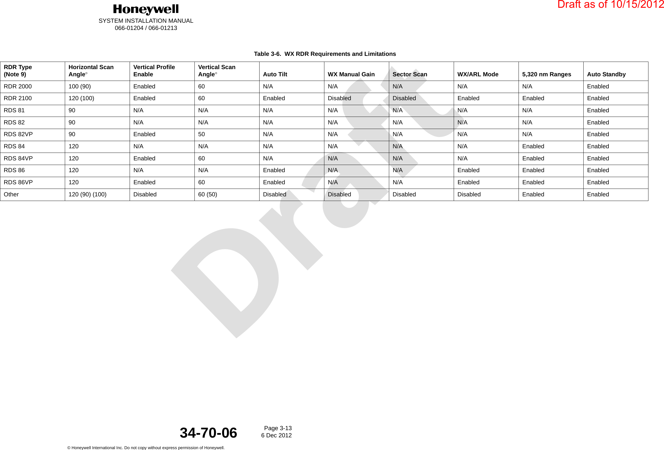
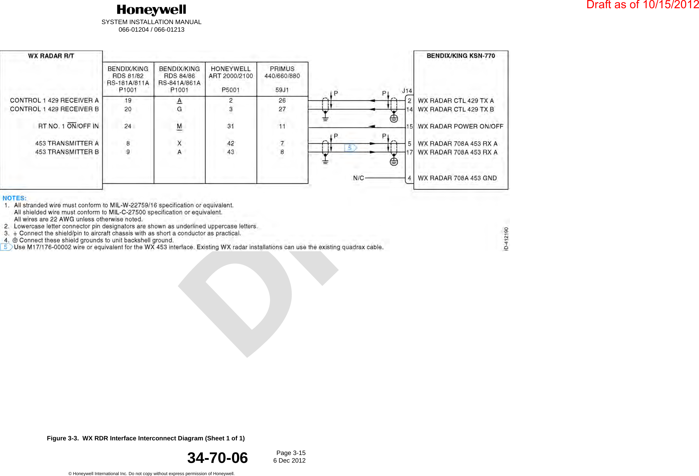
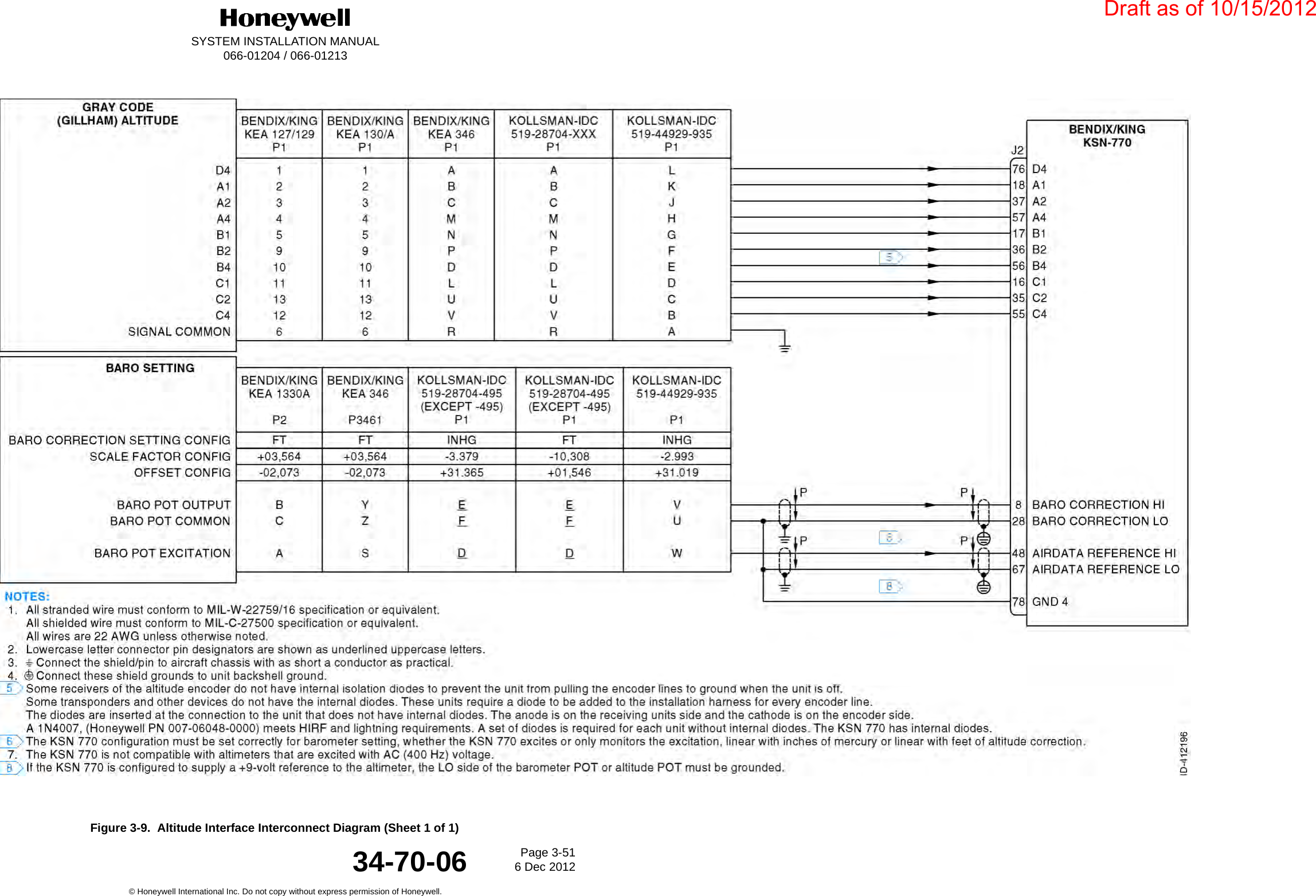
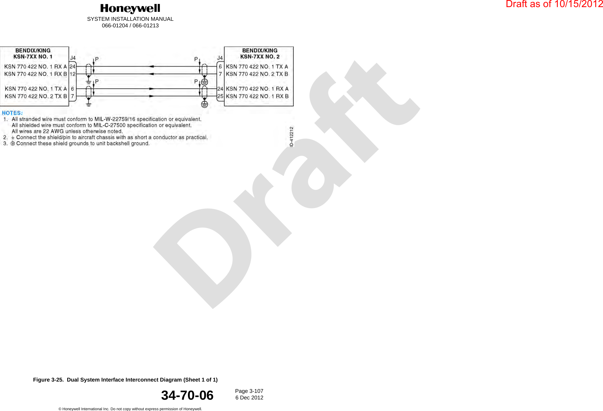
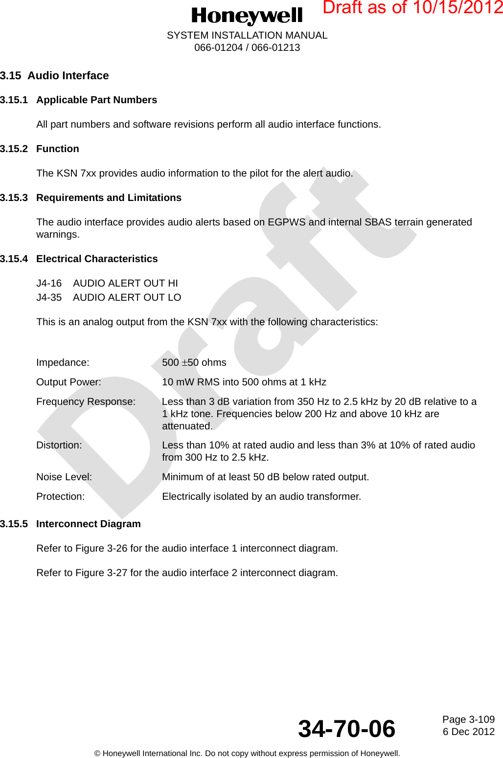
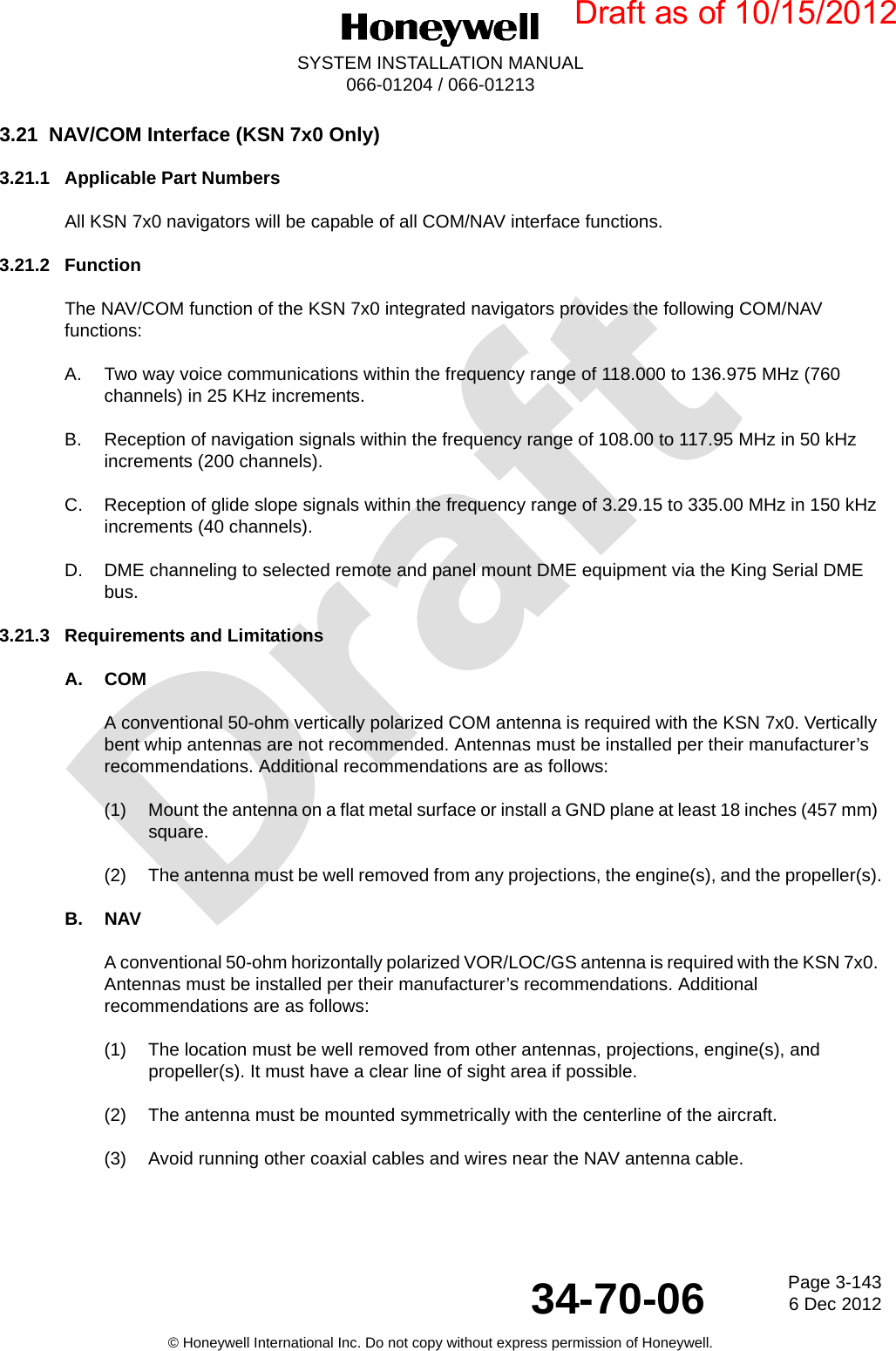
![DraftPage 2-456 Dec 201234-70-06SYSTEM INSTALLATION MANUAL066-01204 / 066-01213© Honeywell International Inc. Do not copy without express permission of Honeywell.2.3.8 KSN Power DistributionThe KSN 7xx is powered through two dedicated circuit breakers. A 10.0 AMP circuit breaker powers the MMDS radio system. A 7.5 AMP circuit breaker powers the rest of the KSN 7xx functions. These circuit breakers must be connected to the same power bus sources. The power bus can range from +11 to +33 VDC. For aircraft weighing less than 6000 pounds (2721.6 kg) with two KSNs, it is recommended that each KSN is powered from a separate power bus. For aircraft weighing more than 6000 pounds (2721.6 kg) with two KSNs, it is required that each KSN is powered from a separate power bus.2.3.9 Placards and LabelsAll placards and labels must be visible in all lighting conditions. Text must be a minimum of 0.10 inch (2.5 mm) in height, and must be a contrasting color to the background of the label/placard. Text must be permanent and not easily disfigurable. If the KSN is not configured for IFR operation, a placard stating “The KSN 7xx is limited to VFR use only” (or similar) must be installed in the pilots field of view.2.3.10 Weight and BalanceUsing component weights from Table 2-23 and the moment arm of the component mounting locations, perform a weight and balance calculation per AC 43-13-1B Chapter 10. Also account for equipment remove during the modification process.Table 2-23. Component WeightsComponent WeightKSN 770 (standard, includes KCM 200 and rack) 9.9 pounds (4.5 kg)KSN 770 (with WX RDR/EGPWS) 10.2 pounds (4.6 kg)KSN 765 (standard, includes KCM-200 and rack) 8.1 pounds (3.7 kg)KSN 765 (with WX RDR/EGPWS) 8.4 pounds (3.8 kg)GPS Antenna (KA-96) Refer to KA 96 IM (0.5 pounds [0.2 kg] nominal)Annunciator Panel Refer to the manufacturers dataNAV Antenna Refer to the manufacturers dataCOM Antenna Refer to the manufacturers dataIndicator Refer to the manufacturers dataDraft as of 10/15/2012](https://usermanual.wiki/Honeywell/KSN770/User-Guide-1912820-Page-85.png)

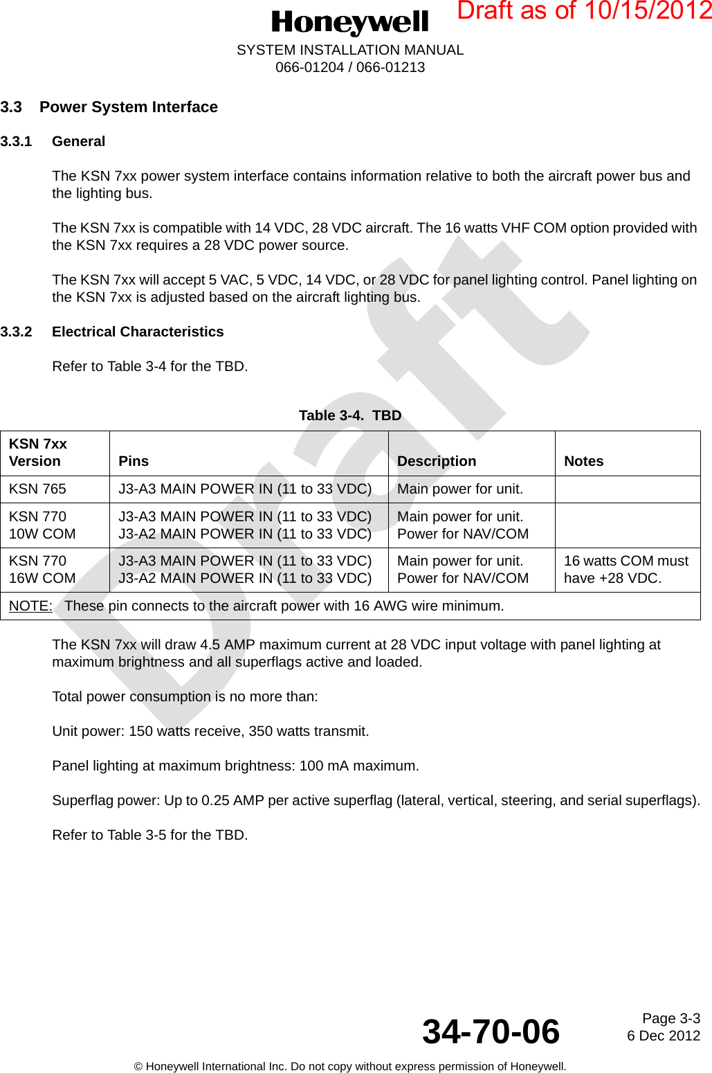
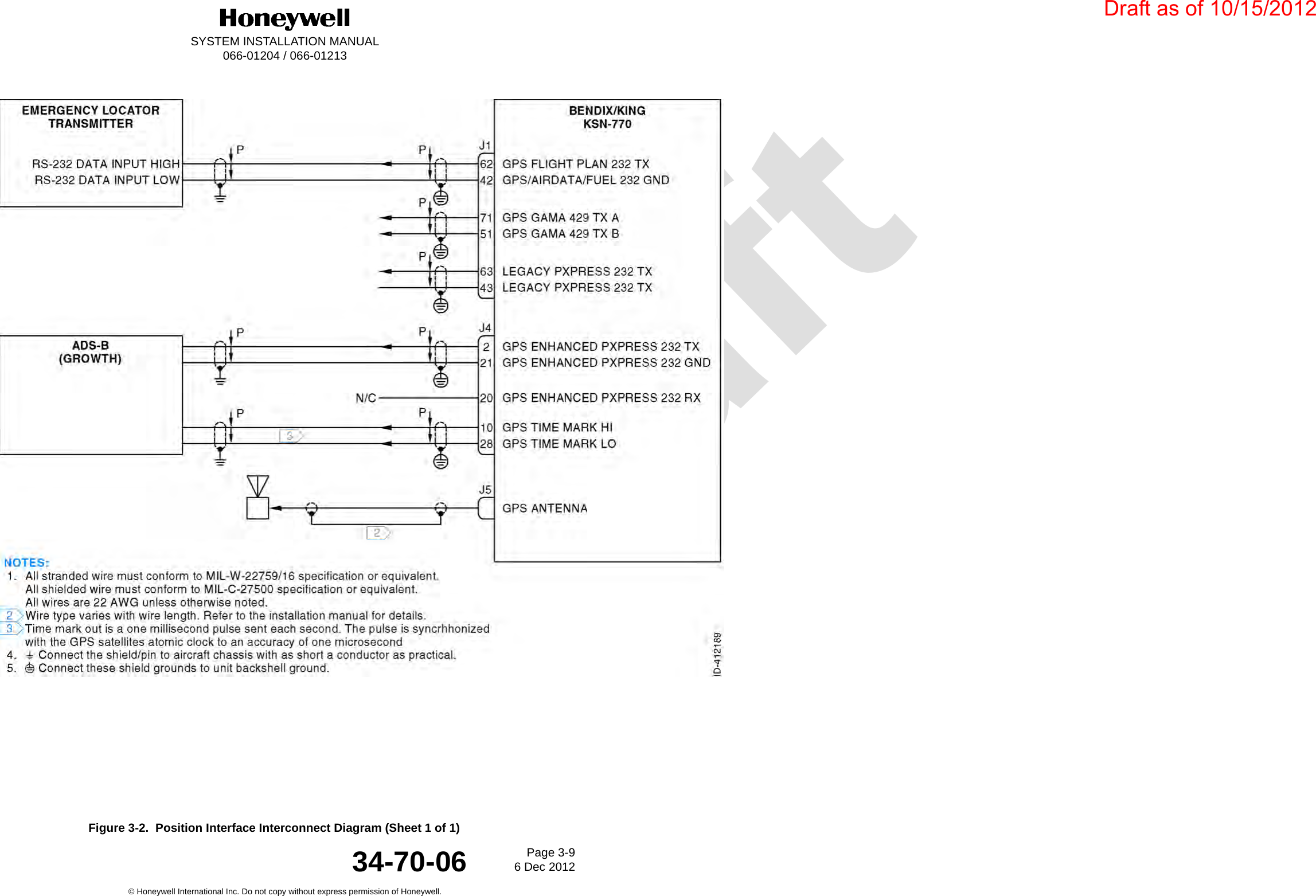
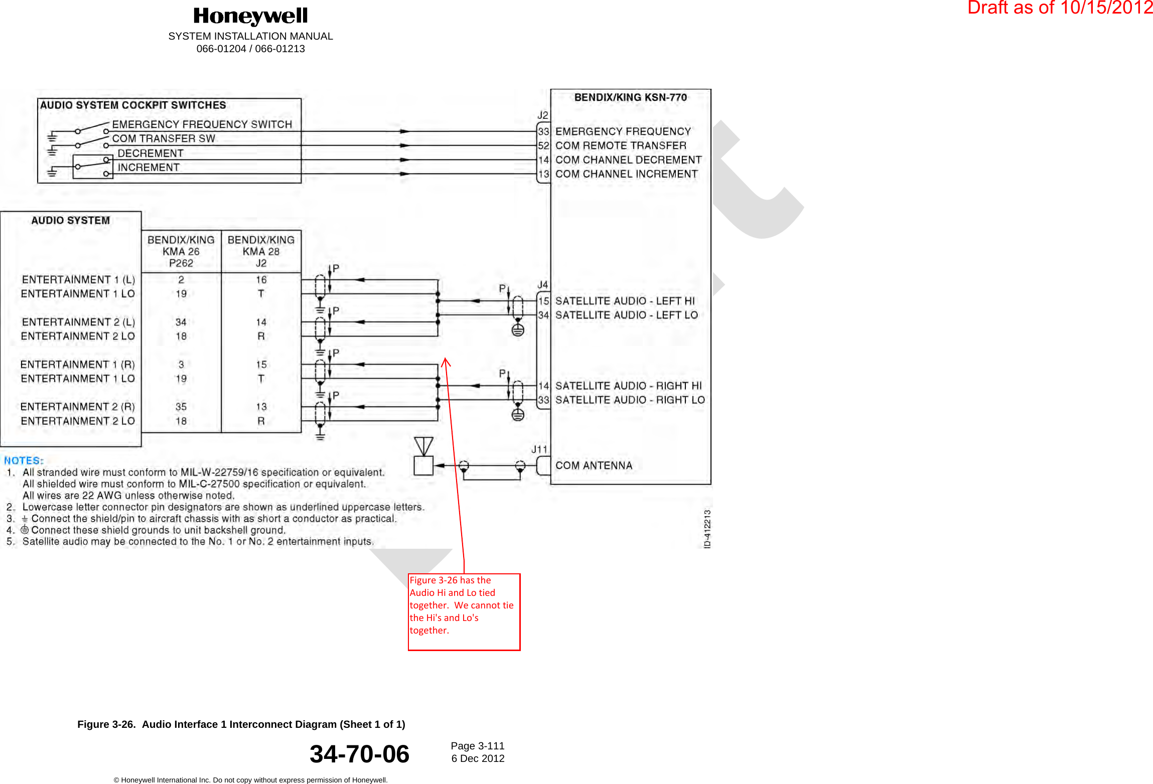
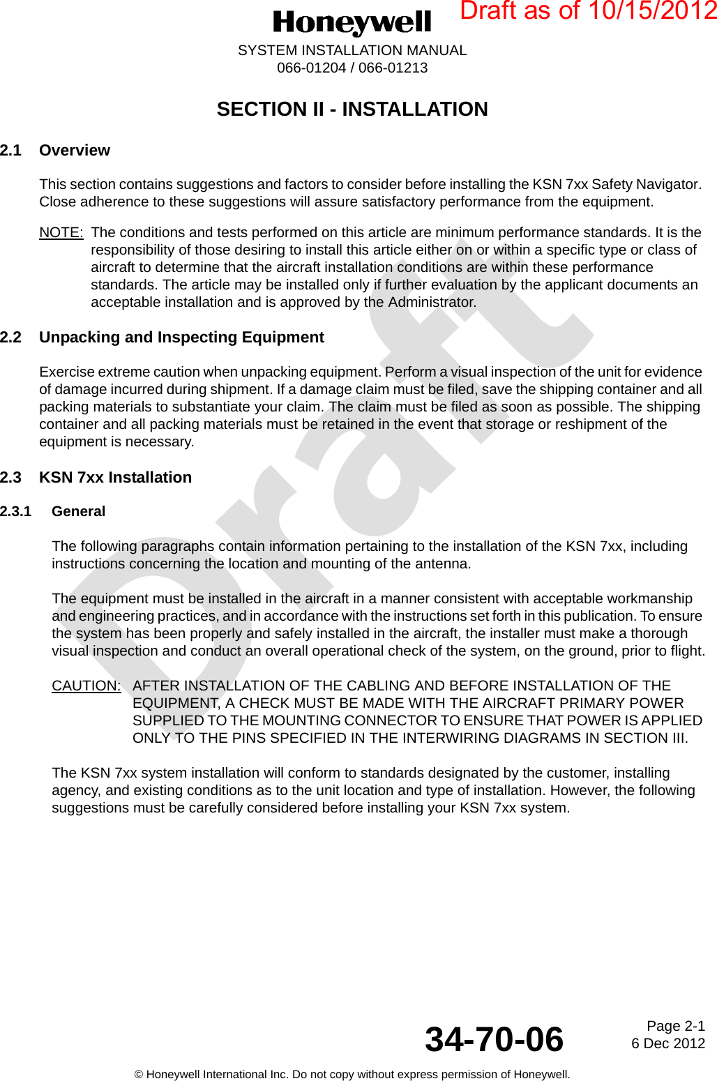
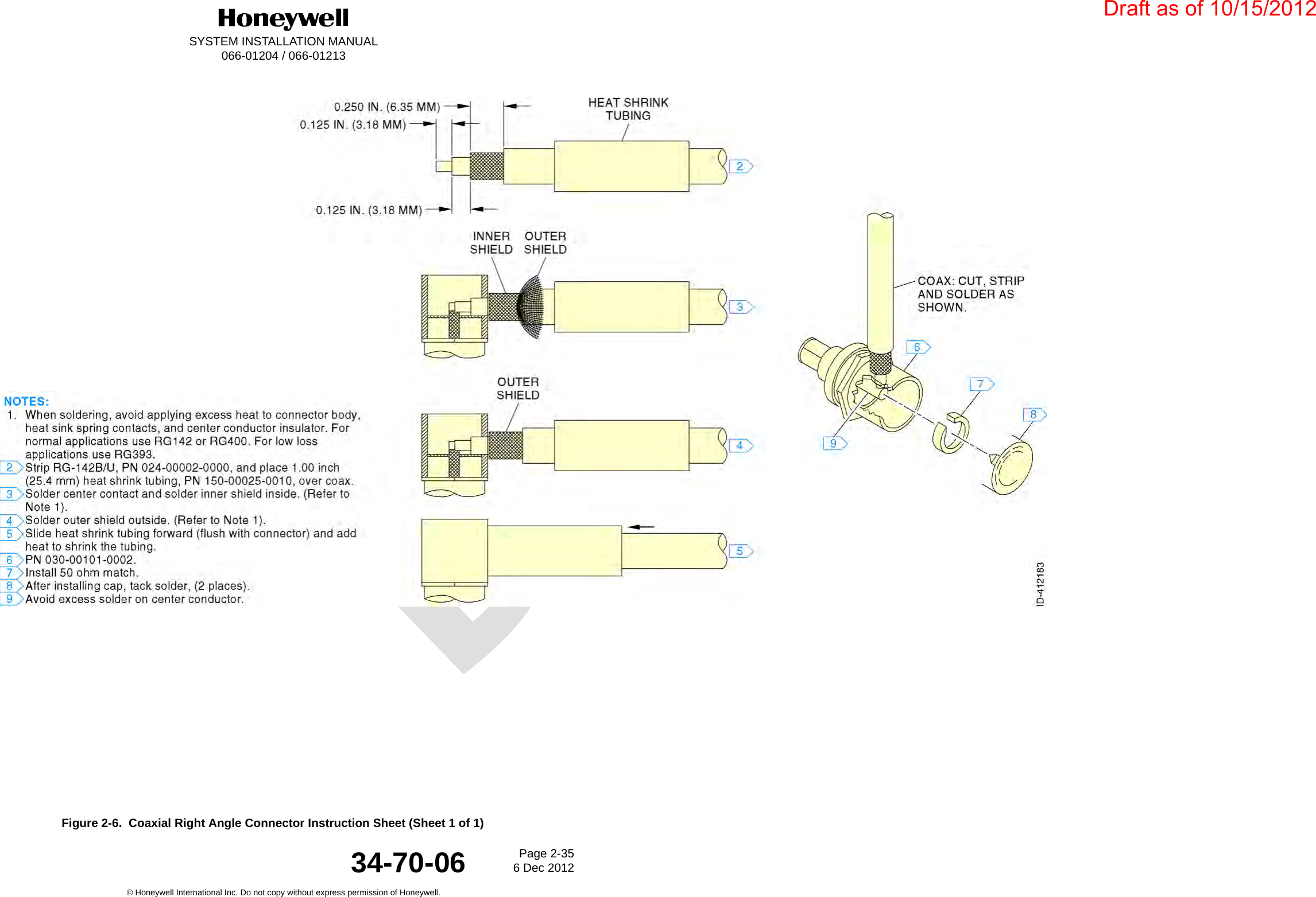
![DraftPage 2-496 Dec 201234-70-06SYSTEM INSTALLATION MANUAL066-01204 / 066-01213© Honeywell International Inc. Do not copy without express permission of Honeywell.2.4.2 COM and NAV Antenna Installation Considerations2.4.2.1 COM Antenna LocationThe VHF COM antenna must be mounted as far away as possible (8.0 feet [244 cm] minimum) from other similar antennas and the vertical stabilizer. Mounting the COM antenna as far away as possible from the navigation antenna will help reduce COM to NAV interference. The COM antenna must also be mounted as far away as possible from an ELT antenna to prevent distortion of the radiated pattern and to prevent radiated broadband noise from affecting the ELT when excited by the COM transmissions. Radiated broadband noise from an ELT is a common cause of COM-to-COM and COM-to-NAV interference. Mounting one antenna on top of the fuselage at the highest location to ensure a good radiation pattern and the other on the bottom of the fuselage offers good separation with a minimum of interaction.It is recommended that one COM transceiver be connected to the top antenna for good GND communication and that the other COM transceiver be connected to the bottom antenna to provide good airborne communications. If mounting antennas on the same side of the aircraft is unavoidable, maintain the minimum allowable separation (8.0 feet [244 cm]).The antenna must be mounted on a section of the aircraft that is horizontal during cruise flight. The base of the antenna must be well bonded to the metal aircraft skin. Remove any paint from around the mounting holes to ensure a good connection between the antenna and the skin. The metal aircraft skin at the base of the antenna must extend a minimum of 24.0 inches (610 mm) in every direction. This provides the GND plane required for the antenna. Any less metallized area will result in reduced communication range at some bearings around the aircraft and may increase interference to and from other systems.The COM transceiver performance depends heavily on the integrity of the electrical bonding to the airframe and also the electrical integrity of the aircraft structure. If the electrical resistance between an antenna and the aircraft or between adjacent skin panels changed intermittently, noisy communications may result.Connect the antenna to the COM unit with 50-ohm coaxial cable, keeping the cable length to a minimum and avoiding sharp bends in the cable. Keep the COM antenna cable as far away from other antenna cables as possible and do not bundle several antenna cables together. Prepare the cable to the BNC connector as shown in Figure 2-6.Use Dow-Corning DC-4, or equivalent, on both inside and outside of the connector and its mate as an effective barrier against moisture and to prevent corrosion.2.4.2.2 NAV Antenna LocationThe NAV antenna must be well removed from other antennas, projections, engines or propellers. It must have a clear line of sight area if possible. The antenna must be mounted symmetrically with the center line of the aircraft. Avoid running other coaxial cables and wires near the NAV antenna cable.The VOR/LOC antenna with Glideslope is a two piece dipole with one part mounted on each side of the vertical stabilizer. It must be installed on the upper section of the vertical stabilizer of single finned aircraft and be at least 28.0 inches (711 mm) (measured vertically) from the horizontal stabilizer.Draft as of 10/15/2012](https://usermanual.wiki/Honeywell/KSN770/User-Guide-1912820-Page-89.png)