KJ TECH KJ-3300 Biometrics Fingerprint Reader User Manual Manual
KJ TECH Biometrics Fingerprint Reader Manual
UserManual.wiki
>
KJ TECH
>
KJ-3300 User Manual
>
Manual
Contents
1.
Manual
2.
Manual Addendum
Manual
Navigation menu
Upload a User Manual
Namespaces
Wiki Guide
HTML
PDF
Info
Views
User Manual
Discussion / Help
Navigation

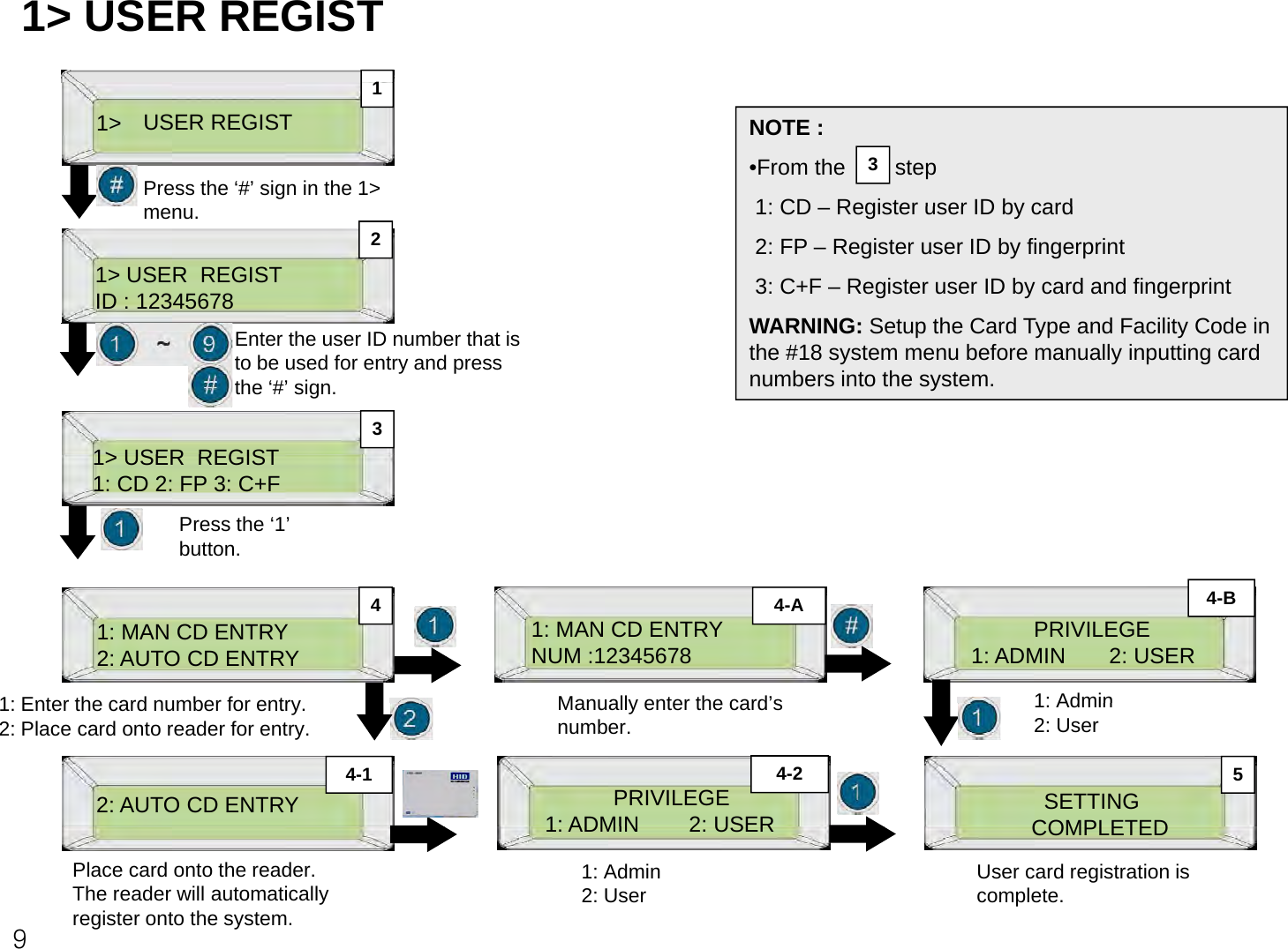
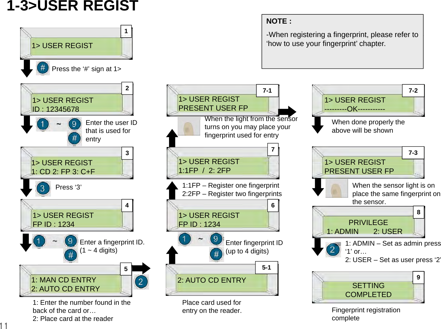
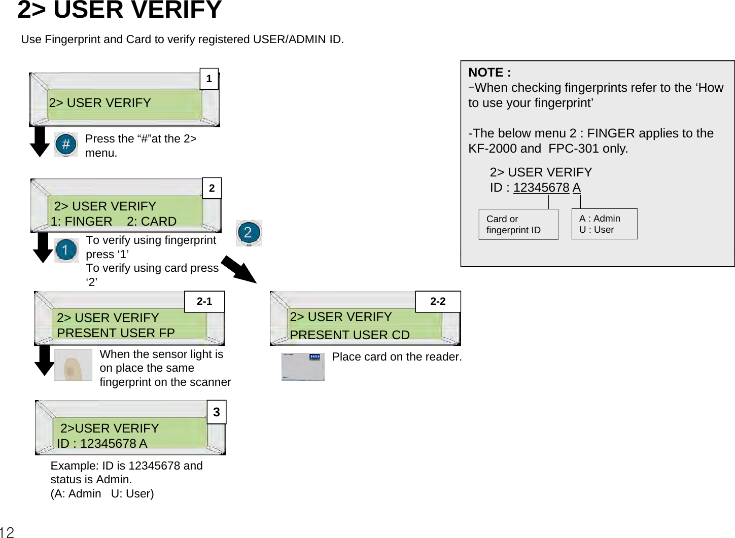
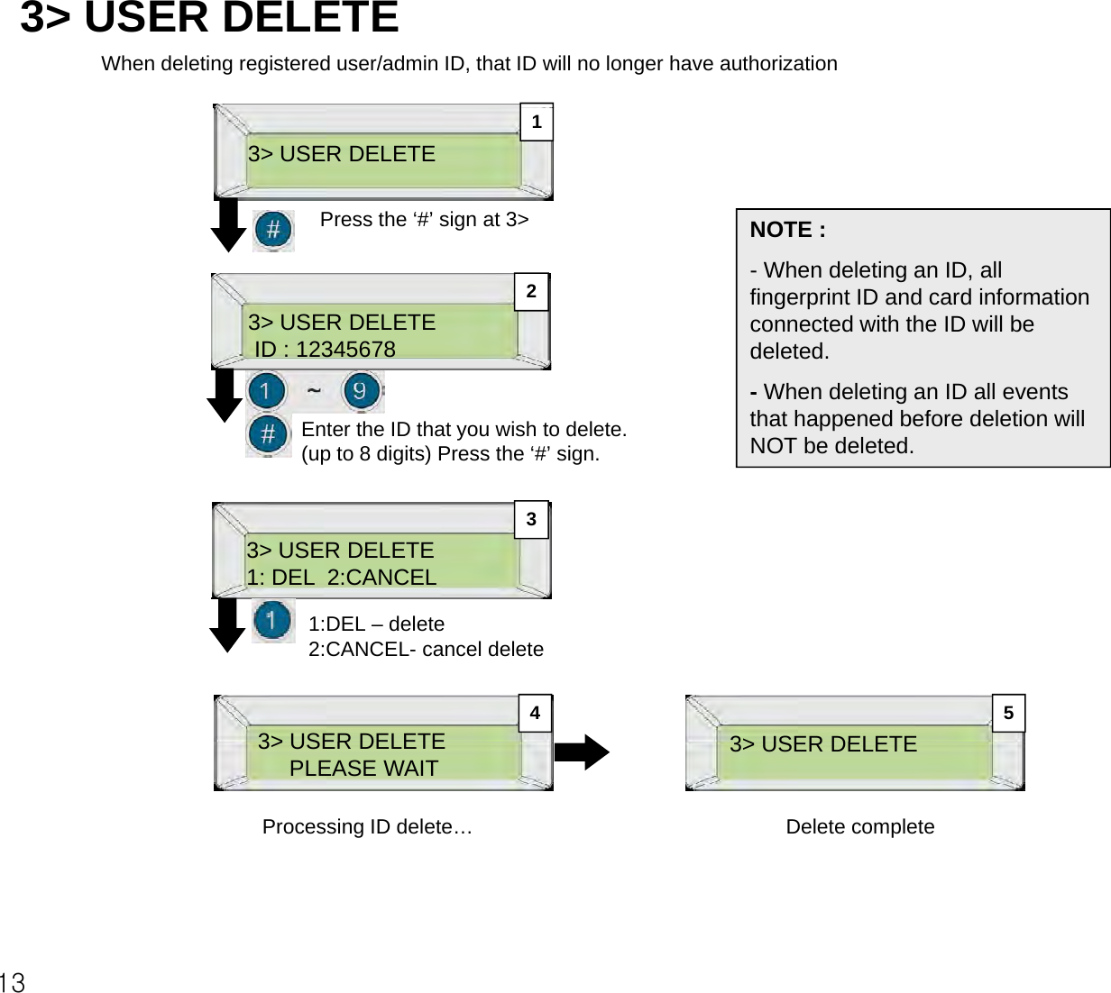
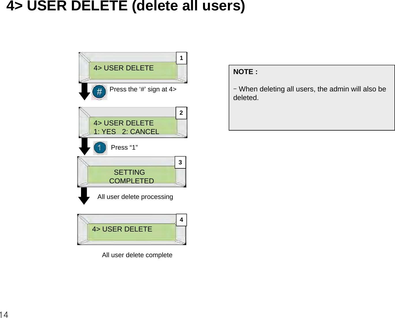
![Beginning – QUICK START 1When beginning the ADMIN (access control manager) should NOT be registered. When the ADMIN is not registered access the menu by pressing“ID”and“1234”(After registering the ADMIN the ID“1234”will not work and only theaccess the menu by pressing ID and 1234. (After registering the ADMIN the ID 1234 will not work and only the ADMIN ID will be able to access) How to access the menu:* When ADMIN is not registered * When ADMIN is registeredNOTE : When accessing the menu,-When ADMIN is not registered,gg1. Turn on the power.2. Follow the following steps.11-11. Turn on the power.2. Follow the following steps.Use ID“1234” to verify.-When ADMIN is registered,Only the ADMIN ID can verify.[ A N Y M O D E ]16: 10: 46 [WED]Press the ‘*’ sign.[ANY MODE]16: 10: 46 [WED]Press the ‘*’ sign to access the Administrator mode.VALIDATE ADMINID : 1234 VALIDATE ADMINID : 123456781> USER REGIST21-2 1-5After entering“1234”press the‘#’Enter the Admin ID and press If shown like the above, you have 1> USER REGISTVALIDATE ADMINVALIDATE ADMINPRESENT USER FP31-31-4After entering 1234 press the # sign.pthe ‘#’ sign.(the above is when the AdminID is “12345678”)accessed the system menu.VALIDATE ADMIN1:FP 2:CARDPRESENT USER FPIf shown like the above you have accessed the system menu. Decide how the Admin will be verified.When a red light is on in the fingerprint screen, place the Admin’s fingerprint on the scanner. Do not lift until the light is off. 3For first time registering:- To verify with fingerprint press 1(FP). - To verify with card press 2.](https://usermanual.wiki/KJ-TECH/KJ-3300.Manual/User-Guide-1817641-Page-3.png)
![BEGINNING – QUICK START 2 - MENU -Menu navigation buttons1> USER REGIST2> USER DELETE3> USER DELETE4> USER ALLDELgFORWARD BUTTONBACK BUTTON5> USER COUNT6> USER VIEW7> USER FP EDIT8> USER TEMP ID9> EVENT VIEWEND MENU AND RETURN TO BEGINNINGEXIT MENU 10> EVENT COUNT11> EVENT DELETE12> DOOR RELAY13> DOOR MODE14>DOOR TIME[ A N Y M O D E ] 16: 10: 46 [WED]GGPROCESS314 DOOR TIME15> DOOR ALARM16> SET COMM ID17> SET TIME18> SET CD TYPE19> SET FG TYPE[ A N Y M O D E ] 1> USER REGIST119> SET FG TYPE20> SET REACCESS 21> SET CD2 FUN22> SET ALM FUN23> SET ANTIPASS [O]16: 10: 46 [WED]Press the ‘*’ sign.24> SET FIRE25> SET SECRET 35> TCP/IP DHCP26> SET LIMIT 36>IP ADDRESS27> SET DAYLIGHT 37> SUBNET MASK28> VIEW AT-FUNC 38>GATEWAY2VALIDATE ADMINID : 1234 Menu Access29> VIEW AT-DOOR 39> LANGUAGE30> VIEW AT-MODE 40> SAVE ENROLL31> VIEW BELL 41> LOAD ENROLL32> VIEW T-ZONE 42> SAVE SLOG33>VIEW NOFUN 43> SAVE GLOG4After entering the Admin ID press the ‘#’ sign.(If the Admin ID does not exist,press “1234” to access the menu)33>VIEW NO-FUN 43> SAVE GLOG34> S/W VERSION 44> EXIT](https://usermanual.wiki/KJ-TECH/KJ-3300.Manual/User-Guide-1817641-Page-4.png)
![ADMIN REGISTRATION1> USER REGIST 1> USER REGIST1910[ANY MODE]16: 10: 46 [WED]-----------OK--------- PRESENT USER FPPress the ‘*’ sign to access the admin menu.When the machine accepts the fingerprint or card correctly the above will be shown.To make sure enter one more time.If its ‘2FP’ enter a different fingerprint8111> USER REGIST PRESENT USER FP2The above shows when ‘FP’(fingerprint) is selectedPRIVILEGE 1: ADMIN 2: USERPress ‘1’(1:Admin 2:User)VALIDATE ADMINID : 12348111> USER REGISTSETTINGCOMPLETE3After entering “1234” press the ‘#’ sign the enter the menu. (fingerprint) is selected. When the sensor emits a lightplace the finger to be used. -(1:Admin 2:User)1> USER REGIST7121> USER REGISTComplete1: 1 FP / 2: 2 FPNOTE :Press the ‘#’ sign to process.The above shows when ‘FP’ is selected.-FP 1 : Register 1 fingerprint-FP 2 : Register 2 fingerprints41> USER REGISTFP ID : 1234Enter fingerprints ID.1~4 digits)NOTE :- Admin authority is given to a users ID. Therefore, an Admin’s card or fingerprint can be reused to a new user’s ID. 1> USER REGISTID : 1234567861> USER REGIST1: CD 2: FP 3: CD/FPEnter an ID number to be used, up to 8 digits and press the ‘#’ sign. Decide which will be used for entrance.gp g)55pesst e # sg1.CD : Card2.FP : Fingerprint3.CD/FP : Card and FingerprintPress the ‘#’ sign after selection.](https://usermanual.wiki/KJ-TECH/KJ-3300.Manual/User-Guide-1817641-Page-5.png)

![1. SYSTEM MENU ACCESS(AFTER ADMIN IS REGISTERED)NOTE :Only when the admin is registered (referREGISTERED)[ A N Y M O D E ] 16:10:46[WED]1-1-Only when the admin is registered. (refer to pg13 for instructions)-When the admin ID is incorrect, access to the menu is denied and the screen will t t th i iti l16:10:46[WED]1-2The screen above shows the initial screen.Press the ‘*’ sign.return to the initial screen.-If the admin is not registered, access to the menu is allowed. It is a good idea to register at least one admin.VALIDATE ADMINID : 123456781-2Enter the admin ID and press the‘#’sign.gVALIDATE ADMIN 1-3 1-5the # sign.(the above shows when the admin ID is ‘12345678’.)VALIDATE ADMIN1-41. USER REGIST1:FP 2:CARDSelect what to use when registering for admin.1: Fingerprint 2:CardPRESENT USER FPAccess to the system menu.Press F1 and F2 to access a menu.Use fingerprint used to register admin ID.VALIDATE ADMINPRESENT USER CD1-4gpUse card used to register 8admin ID.](https://usermanual.wiki/KJ-TECH/KJ-3300.Manual/User-Guide-1817641-Page-8.png)
![8> USER TEMPORARY ID When a temporary user needs to enter, but doesn’t need to register (Ex. visitor, guest)NOTE :1 48> USER TEMP IDPress the ‘#’ sign at 8>SETTINGCOMPLETEDTemporary ID complete-Cannot register temporary ID as admin.-Cannot register temporary ID with8> USER TEMP IDID : 12345678 8> USER TEMP IDTIME [1 - 9] : 3Cannot register temporary ID with fingerprint.-When properly registered the following is shown:WELCOME [F00]23Enter a temporary ID number (up to 8 digits) and press the “#” sign.Enter the amount the temporary user is allowed to enter and press the “#” sign. (minimum 1, maximum 9)WELCOME [F0-0]ID: 12345678 T(T : Temporary)-The admin can set the amount of entries of a temporary ID.(1-9)-When the amount of entries are used, the Admin is able to add more entries allowed for the temporary ID.py-Events are recorded the same way as regular user ID.Cannot register temporary ID from17-Cannot register temporary ID from regular user ID.](https://usermanual.wiki/KJ-TECH/KJ-3300.Manual/User-Guide-1817641-Page-17.png)
![9> EVENT VIEW View user ID time of entry, date, access authorization, system authorization.9> EVENT VIEWNOTE :1Press ‘#’ at the screen above.NOTE :EVENT OVERVIEW- MASTER MENU IN : Access Admin menuMENU MODE EXIT E it Ad i21. SLOG 2. GLOG -MENU MODE EXIT : Exit Admin menu- MASTER MENU FAIL : Admin menu Access failed- 12345678 [GRANTED] : ID/fingerprint 12345678 entry- 12345678 [DENIED] : ID 12345678 Access failed- USER FG REG : Register user fingerprint1. SLOG : Access Event2. GLOG: Exit Eventggp- USER CD REG : Register user Card- FINGER DOWNLOAD : Download fingerprint- CARD DOWNLOAD : Download card- NONE : No event0001 : 09/06 15:09MASTER MENU IN39> EVENT VIEW MENU NAVIGATION BUTTONS NEXT EVENT44The example above shows that the admin accessed the admin menu at 9/6 at 15:09.0002 :[NONE]To exit press ‘*’ when the NEXT EVENTBACK EVENT418screen above appears.(The example above shows no event.)EXIT](https://usermanual.wiki/KJ-TECH/KJ-3300.Manual/User-Guide-1817641-Page-18.png)
![12> DOOR RELAYThis menu is for changing the functions of Relay 1 and 2. Normally Relay 1 controls the door.In cases where Relay 1 cannot be used, the user can change and use Relay 2 to control the door.12> DOOR RELAY 1Press the ‘#’ sign at 12>3212> DOOR RELAY1 : RLY 2 : RLY [1]When Relay 1 is controlling “Door Control”To change to Relay 2,Press “2”SETTINGCOMPLETEDRelay setup complete32Control”Press “2”13> DOOR MODE In this menu the user is allowed to setup door modes according to certain situations. There are a total of 15 ways. This page only shows how to setup.13>DOOR MODEList navigation menu NOTE :113 DOOR MODE Press the ‘#’ sign at 13>forwardback- When accessing the menu, the current mode used will be shown. Press “F1” to change to a different mode and press the”#”signt2013> DOOR MODE[ ID or FP ] exitmode and press the # signsetup2](https://usermanual.wiki/KJ-TECH/KJ-3300.Manual/User-Guide-1817641-Page-20.png)
![13-1> DOOR MODE (detailed auto door mode instructions)[Open] : Always Open (Fail-Safe Mode) [Close] : Always Closed (Fail-Secure Mode) – no access with any form of authorization[FINGER] : Fingerprint Only – no access with ID or card[CD] : Card Only – no access with ID or fingerprint NOTE :[ID or FP] : ID or Fingerprint Only – no access with card[ID or CD] : ID or Card Only – no access with fingerprint [CD or FP]: Card or Fingerprint Only –no access with ID-For fingerprint disabled personnel, any mode of ID entrance is allowed, except for [CLOSE] mode.[] gpy[Any Mode]: Any Form of Authorization - access granted with any form of authorization [ID and FP]: Both ID and Fingerprint Required for Access – must punch in ID before fingerprint authentication [ID and CD]: Both ID and Card Required for Accessmust punch in ID before Card authentication[ID and CD]: Both ID and Card Required for Access –must punch in ID before Card authentication [CD and FP]: Both Card and Fingerprint Required for Access – card must be authorized before fingerprint authentication[ID&FP]or[CD&FP] : both ID and Fingerprint or both Card and Fingerprint are required for Access[ID&FP]or[CD] : both ID and Fingerprint or just Card are required for Access[ID&FP]or[ID&CD] : both ID and Fingerprint or both ID and Card are required for Access[ID & CD & FP]: all three forms needed for access[CD]NOTE :The operation mode described above is shown in the graphic 21[ CD ] 16: 10: 46 [WED]gpon the right located in the dotted square](https://usermanual.wiki/KJ-TECH/KJ-3300.Manual/User-Guide-1817641-Page-21.png)
![16> SET COMM ID (controller address setup)When networking several controllers to a computer, each controller needs its own unique address. This menu is to designate controllers a unique address or edit/change an existing address. (users are recommended to seek advice)16> SET COMM ID 1Press ‘#’ when the above is shown.216> SET COMM ID[01] 1-16 = 022Choose between 1~16 that will be the address and press “#”.SETTING3COMPLETED Address setup complete-SF-3000 can each have address from 1-16Users must designate an address to each product that is connected. If the S/W is installed to the computer, it can be done from there.23SF-3000 can each have address from 1-16 -The factory default setting is ‘1’. For more details refer to the ‘installers instruction manual’](https://usermanual.wiki/KJ-TECH/KJ-3300.Manual/User-Guide-1817641-Page-23.png)
![20> SET REACCESS (authorization security setup)This function was created to decrease the troublesome situations of using a card again after a fingerprint is read as an error when a fingerprint scan is required after a card scanan error when a fingerprint scan is required after a card scan. 20> SET REACCESSNOTE :- If an admin is registered by a fingerprint, 1Press the ‘#’ sign at 20>authorization security is not in effect when accessing the system menu.220> SET REACCESS[ 3 ] 0-9 : 5Enter the amount of times a re-scans allowed. Press the SETTINGCOMPLETEDAuthorization security setup23“#” sign after setup. (maximum : 10)Authorization security setup complete 21> SET CD2 FUN (external reader function key)If a controller is connected to a reader, this function gives a function key to the external reader automatically, thus a an automatically setup function key is given to a user who is authorized from an external reader. Events of user entries from the reader are stored. (Ex. For time & attendance)21> SET CD2 FUNP th ‘#’ i t 2121> SET CD2 FUN[F1-0] FUN= F2-1Select a key you wish to SETTINGCOMPLETEDEt l d f ti k12 327Press the ‘#’ sign at 21>yysetup as a function key from F1 through F4 and enter a number (0-9)External reader function key setup complete](https://usermanual.wiki/KJ-TECH/KJ-3300.Manual/User-Guide-1817641-Page-27.png)
![22> SET ALM FUN (external alarm function setup)When opening a door and entering, an alarm will activate after pressing a set function key and inputting a card, fingerprint or ID number.number.This will be effective to alert security guards or law enforcement when an intruder forces a user to access a door. NOTE :To activate an alarm to indicate an intrusion press the function key at the22> SET ALM FUNP th ‘#’ i t 22To activate an alarm to indicate an intrusion, press the function key at the corresponding user/admin page from the machine and input an ID, fingerprint or card. Screen 2 explanation1: RELAY – activates an external alarm.2 BUZZERit lb f th hi i ti td122> SET ALM FUN1:RELAY 2:BUZZER244Press the ‘#’ sign at 22>2: BUZZER –an internal buzzer from the machine is activated.- Users may setup a function key to a RELAY or BUZZER53422> SET ALM FUN[Buzz] FUN= F0-04Button 1 : External alarm setupButton 2 : Internal buzzer setupAlarm setup completePress a function key from F1SETTINGCOMPLETED522> SET ALM FUN[Relay] FUN= F1-2Alarm setup completePress a function key from F1 key from F1 through F4, then press a button 0 through 9 and press the “#” signthrough F4, then press a button 0 through 9 and press the “#” sign28](https://usermanual.wiki/KJ-TECH/KJ-3300.Manual/User-Guide-1817641-Page-28.png)
![23> SET ANTIPASS (Anti-Pass Back)When a controller is located at an entrance and exit, a user must have permission to exit.(Ex Parking lot management office security etc)(Ex. Parking lot management, office security etc) 23> SET ANTIPASS 23> SET ANTIPASS1:YES 2:NO [1] SETTINGCOMPLETED1 2 3Button 1 : Anti-pass back setupButton 2 : Anti-pass back disable[1] : ‘1’ for anti-pass back setup[2] : ‘2’ for anti-pass back disablePress the ‘#’ sign at 23> Anti-Pass setup complete24> SET FIRE (fire/intrusion detect setup)This function is connected to a fire alert system. An alert signal is activated when there is a fire or intrusion. 24> FIRE-SENSORNOTE :-This function is connected to a fire alert system. An alert signal is activated when 12there is a fire or intrusion and all doors are forced open-Intrusion detect closes all doors when an intrusion is detected.Press the ‘#’ sign at 24>24> FIRE-SENSOR1:YES 2:NO [1] 23SETTINGCOMPLETEDButton 1 : fire detect setup (intrusion detect disable)329Fire/intrusion detect setup complete.)Button 2 : fire detect disable (intrusion setup)[1] : ‘1’ for fire detect setup[2] : ‘2’ for intrusion setup](https://usermanual.wiki/KJ-TECH/KJ-3300.Manual/User-Guide-1817641-Page-29.png)
![25> SET SECRET (ID security)For added security, ID shown in the LED screen will show as “********” when receiving authorization for entry.25> SET SECRETNOTE :-Regardless of the digits of the ID f/dithfllii1Press the ‘#’ sign at 25>25>SET SECRETSETTINGof a user/admin, the following is shown “********” 2325> SET SECRET1:ON 2:OFF [1]Button 1 : ID security setupButton 2 : ID security deactivateSETTINGCOMPLETEDID security setup complete26> SET LIMIT In this menu authorization is given once every set times (units of 10 minutes). 26> SET LIMIT 26> SET LIMIT[MIN]<0-600>] : 010SETTINGCOMPLETED2 31Press the ‘#’ at 26>[MIN] 0600 ] : 010Time is set in units of 1 minute. The above shows “10” therefore is 10 minutesCOMPLETEDEntry limit setup complete3010 minutes. If a user is authorized at AM10:00, the user is unauthorized until AM10:10](https://usermanual.wiki/KJ-TECH/KJ-3300.Manual/User-Guide-1817641-Page-30.png)
![28> VIEW AT-FUNC (View setup function key)This function automatically saves the function key to the event without pressing any function keys only within a set time zone This function is usually used to save users from pressing the function key to sign in and out of work all the time Inthiszone. This function is usually used to save users from pressing the function key to sign in and out of work all the time. In this menu you only have to assign a function key to a set time zone from the program. (See the program manual for edit and setup methods)List navigation button1228> VIEW AT-FUNC [ 01 ] DAY : ALL13:00 18:00 F4-9Next ButtonBack ButtonEitMPress the‘#’sign when theThe above shows: All days 12Exit MenuPress the # sign when the above is shown.yfrom 13:00 to 18:00 “F4-9” function key is automatic set so users do not have to press the function key.29> VIEW ATDOOR ( i t t d ti )29> VIEW AT-DOOR (view set auto door time zones)In this menu times are recorded when an automatic door setup at the program is activated. This menu is used only to view set times for automatic doors. (for editing and setup procedures please refer to the program manual.)29> VIEW ATDOOR[01] DAY ALLList navigation buttonforward2129> VIEW AT-DOOR[ 01 ] DAY : ALL13:00 - 18:00 backexitEx) the automatic doors are in operation from 13:00 to 18:00 Press the ‘#’ sign at 29>32peveryday](https://usermanual.wiki/KJ-TECH/KJ-3300.Manual/User-Guide-1817641-Page-32.png)
![30> VIEW AT-MODE (view time management setup)This function is used for changing activation modes at set times. This is different from the switching modes in menu 13. In this function operation modes are changed automatically Only the operation mode’s set times are shown (for editing and detailedfunction, operation modes are changed automatically. Only the operation mode s set times are shown. (for editing and detailedinformation, please refer to the program manual) List navigation buttonsForward1 230> VIEW AT-MODE [ 01 ] DAY : fri11:00 14:00 [FP]ForwardBackExitEx) from Friday 11:00 to 14:00 operation mode is “FINGER”Press ‘#’ at 30>p31> VIEW BELL31> VIEW BELL In this function, a bell is rung at set times automatically. This is usually used for school classroom bells or alarms. Users are only able to view set bell time zones. (for editing and detailed information please refer to the program manual.)31> VIEW BELL[01]DAY:friList navigation buttonsforward21Press ‘#’ at 31>31> VIEW BELL[ 01 ] DAY : fri11:00 T=005Ex) at Friday 11:00 a bell is rung for 5 secondsbackexit33for 5 seconds.](https://usermanual.wiki/KJ-TECH/KJ-3300.Manual/User-Guide-1817641-Page-33.png)
![32> VIEW T-ZONE The user is able to see saved Timezone Index. This menu is only able to view timezones that are setup.(for editing and detailed explanation please refer to the program manual.)32> VIEW TZONE32> VIEW TZONEList navigation buttonForward1 232> VIEW T-ZONEPress the ‘#’ sign at 32>32> VIEW T-ZONEINDEX: 001 [Y] BackExitView the setup timezone.(Up to 254 functions)(Up to 254 functions)33> VIEW NOFUN (View function keys with no33> VIEW NO-FUN (View function keys with no functions)This menu shows events saved when verification is denied and a door does not open. Users may only view function keys set up in the menu (for editing and detailed information please refer to the program manualkeys set up in the menu. (for editing and detailed information please refer to the program manual.33> VIEW NO-FUN[F1-1] [F2-1]21Press ‘#’ at 33>[F11] [F21][F3-1] [F4-1]Function key is setup as “F1-1” “F2-1” “F3-1” “F4-1”34](https://usermanual.wiki/KJ-TECH/KJ-3300.Manual/User-Guide-1817641-Page-34.png)
![34> S/W VERSION VIEWView the current controllers Firm Ware VersionNOTE:34> S/W VERSIONVER : 3.00NOTE:-The current F/W version is 3.00 and future F/W will be updated.34> S/W VERSION12Press the ‘#’ sign at 34>.35> TCP/IP DHCPExiting the menu.35> TCP/IP DHCP 35>TCP/IP DHCP1. ON 2.OFF [2]1 2Press the ‘#’ sign. TCP/IP DHCP On/Off verification35](https://usermanual.wiki/KJ-TECH/KJ-3300.Manual/User-Guide-1817641-Page-35.png)
![44> EXIT (EXITING THE MENU)Closing the menuNOTE:[CD]12:56:32 [THU]NOTE:-Press ‘F4’ to exit menu at anytime.44> EXIT12Press the ‘#’ sign at 44>. To initial screen40](https://usermanual.wiki/KJ-TECH/KJ-3300.Manual/User-Guide-1817641-Page-40.png)

![How to use the function keyThe Function Key is usually used in for time & attendance.The admin is able to setup a certain value to a function key in the program (F1 = sign in) The admin is then able to find out the sign in status.[ A N Y M O D E ]16 10 46 [THU]ACTIVATING FUNCTION KEY THROUGH FINGERPRINT INPUT[ A N Y M O D E ] 16 10 46 [THU][ A N Y M O D E ]16 10 46 [THU]ACTIVATING FUNCTION KEY THROUGH ID INPUT ACTIVATING FUNCTION KEY THROUGH CARD INPUT16: 10: 46 [THU]16: 10: 46 [THU]16: 10: 46 [THU]++ +1. Press a function key (F1~F4) at the initial screen or press a function key after pressing a number key. 2.Enter the ID number used for1. PRESS A NUMBER KEY AFTER PRESSING A FUNCTION KEY. Press a function key (F1~F4) only or, press a number key after pressing a function key.1. Press a function key (F1~F4) at the initial screen or press a function key after pressing a number key. 2. Enter the ID number used for2. Enter the ID number used for entry.pressing a function key.2. INPUT A FINGERPRINT USED FOR ENTRY.2. Enter the ID number used for entry.NOTE :The function key should be used with the time & attendance program. Only enter a function for the time & attendance and only saves data of entries.42y](https://usermanual.wiki/KJ-TECH/KJ-3300.Manual/User-Guide-1817641-Page-42.png)