KJ TECH KJ-3300 Biometrics Fingerprint Reader User Manual Manual
KJ TECH Biometrics Fingerprint Reader Manual
KJ TECH >
Contents
- 1. Manual
- 2. Manual Addendum
Manual

KJ-3300
USER MANUAL
1
KJTech

QUICK STAR
T
2
Beginning – QUICK START 1
When beginning the ADMIN (access control manager) should NOT be registered. When the ADMIN is not registered
access the menu by pressing
“
ID
”
and
“
1234
”
(After registering the ADMIN the ID
“
1234
”
will not work and only the
access
the
menu
by
pressing
ID
and
1234
.
(After
registering
the
ADMIN
the
ID
1234
will
not
work
and
only
the
ADMIN ID will be able to access)
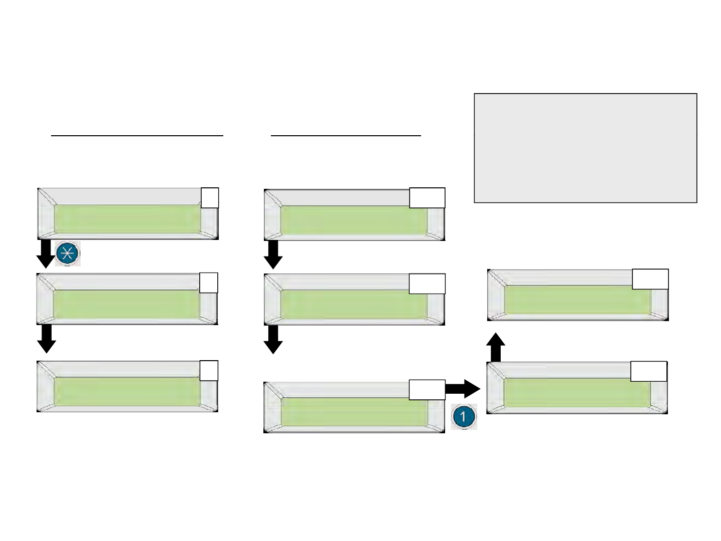
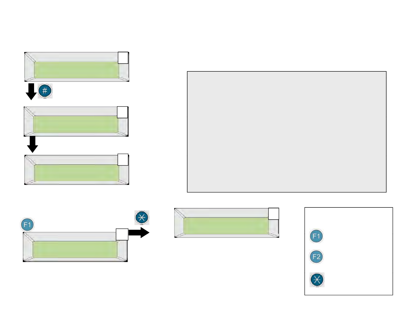
How to access the menu:
* When ADMIN is not re
g
istered * When ADMIN is re
g
istered
NOTE : When accessing the menu,
-When ADMIN is not registered,
g
g
1. Turn on the power.
2. Follow the following steps.
11-1
1. Turn on the power.
2. Follow the following steps.
Use ID“1234” to verify.
-When ADMIN is registered,
Only the ADMIN ID can verify.
[ A N Y M O D E ]
16: 10: 46 [WED]
Press the ‘*’ sign.
[ANY MODE]
16: 10: 46 [WED]
Press the ‘*’ sign to access the
A
dministrator mode.
VALIDATE ADMIN
ID : 1234 VALIDATE ADMIN
ID : 12345678
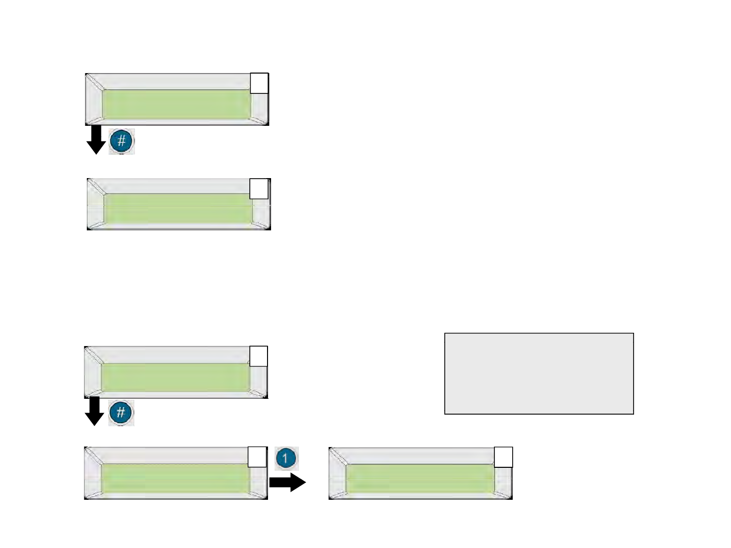
1> USER REGIST
21-2 1-5
After entering
“
1234
”
press the
‘
#
’Enter the Admin ID and
p
ress If shown like the above, you have
1> USER REGIST
VALIDATE ADMIN
VALIDATE ADMIN
PRESENT USER FP
3
1-3
1-4
After
entering
1234
press
the
#
sign.
p
the ‘#’ sign.
(the above is when the Admin
ID is “12345678”)
accessed the system menu.
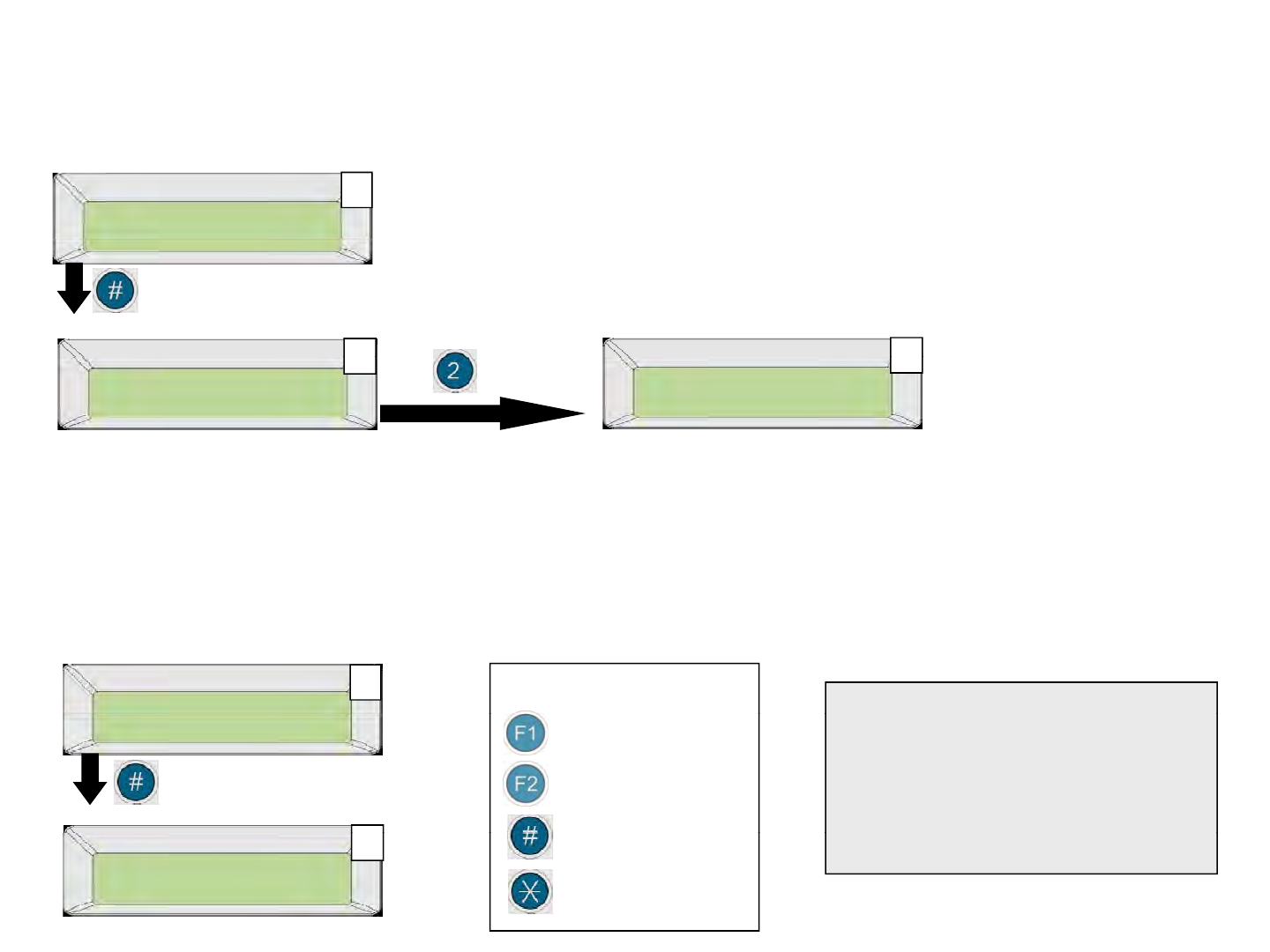
VALIDATE
ADMIN
1:FP 2:CARD
PRESENT
USER
FP
If shown like the above you have
accessed the system menu. Decide how the Admin will be
verified.
When a red light is on in the
fingerprint screen, place the
Admin’s fingerprint on the scanner.
Do not lift until the light is off.
3
For first time registering:
- To verify with fingerprint press
1(FP).
- To verify with card press 2.
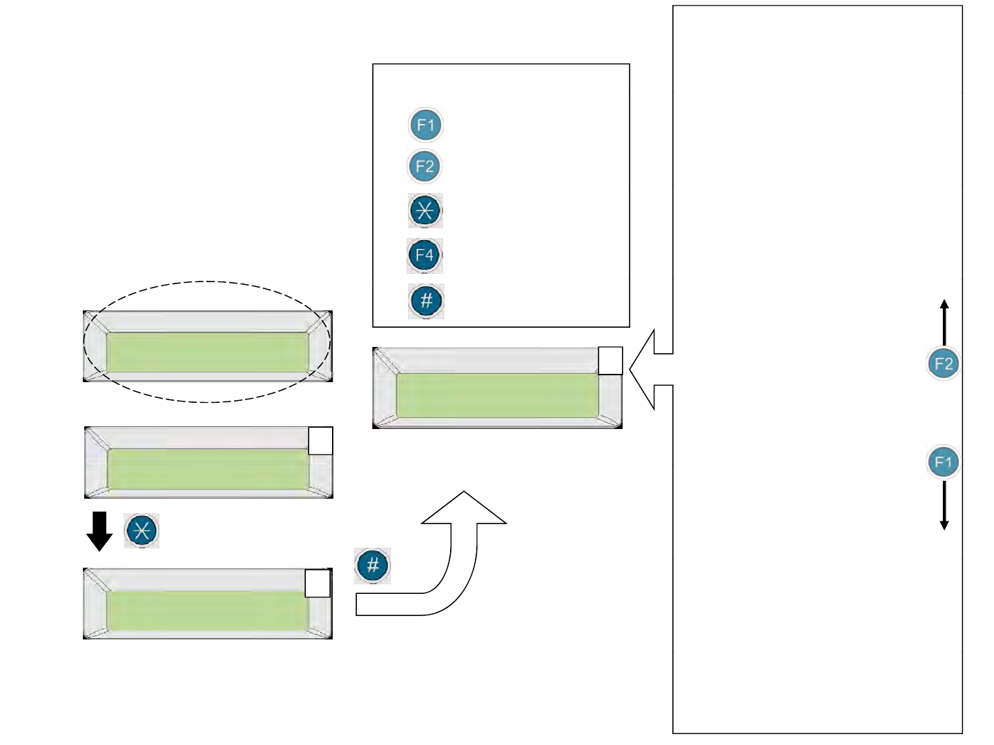
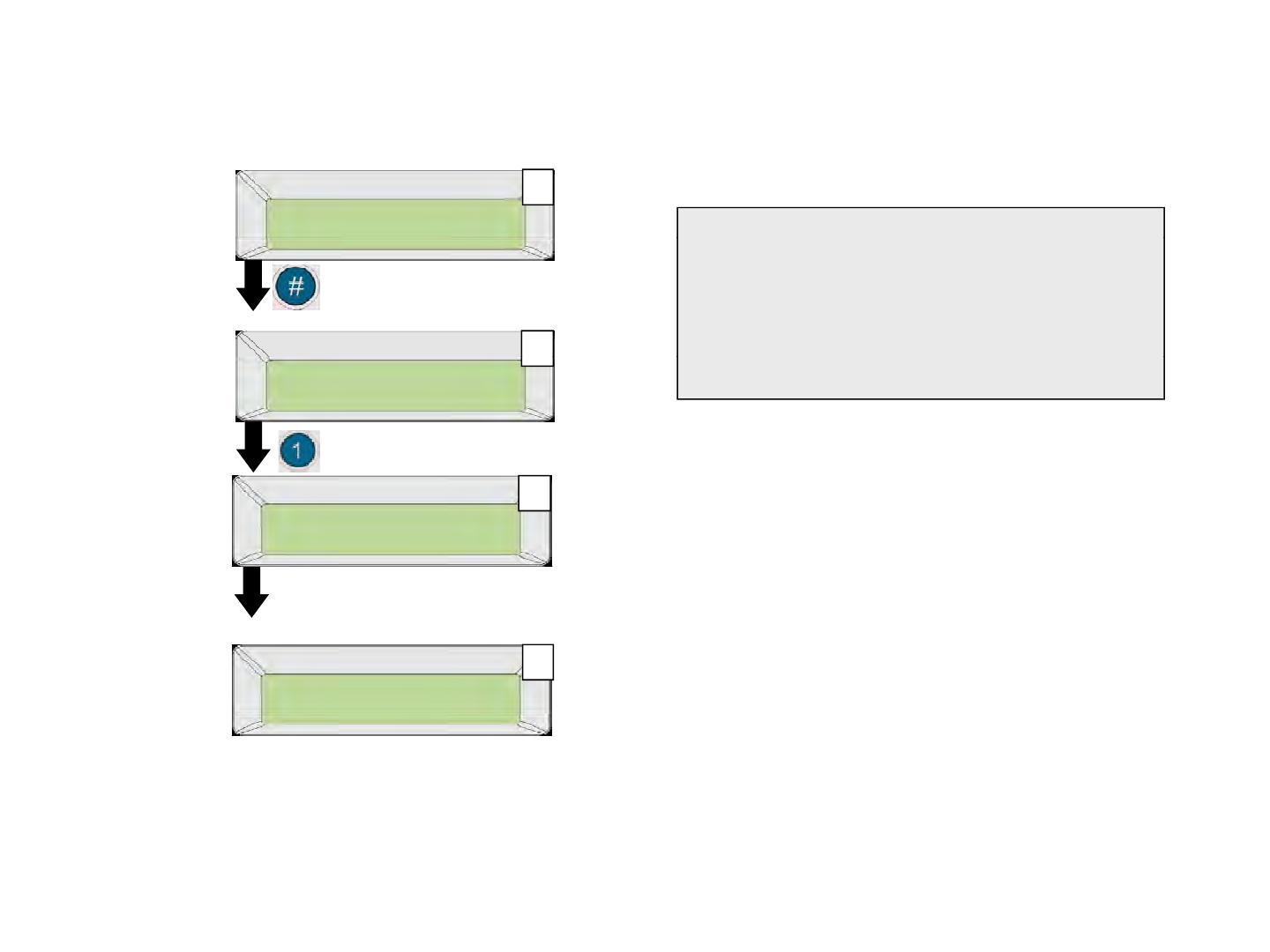
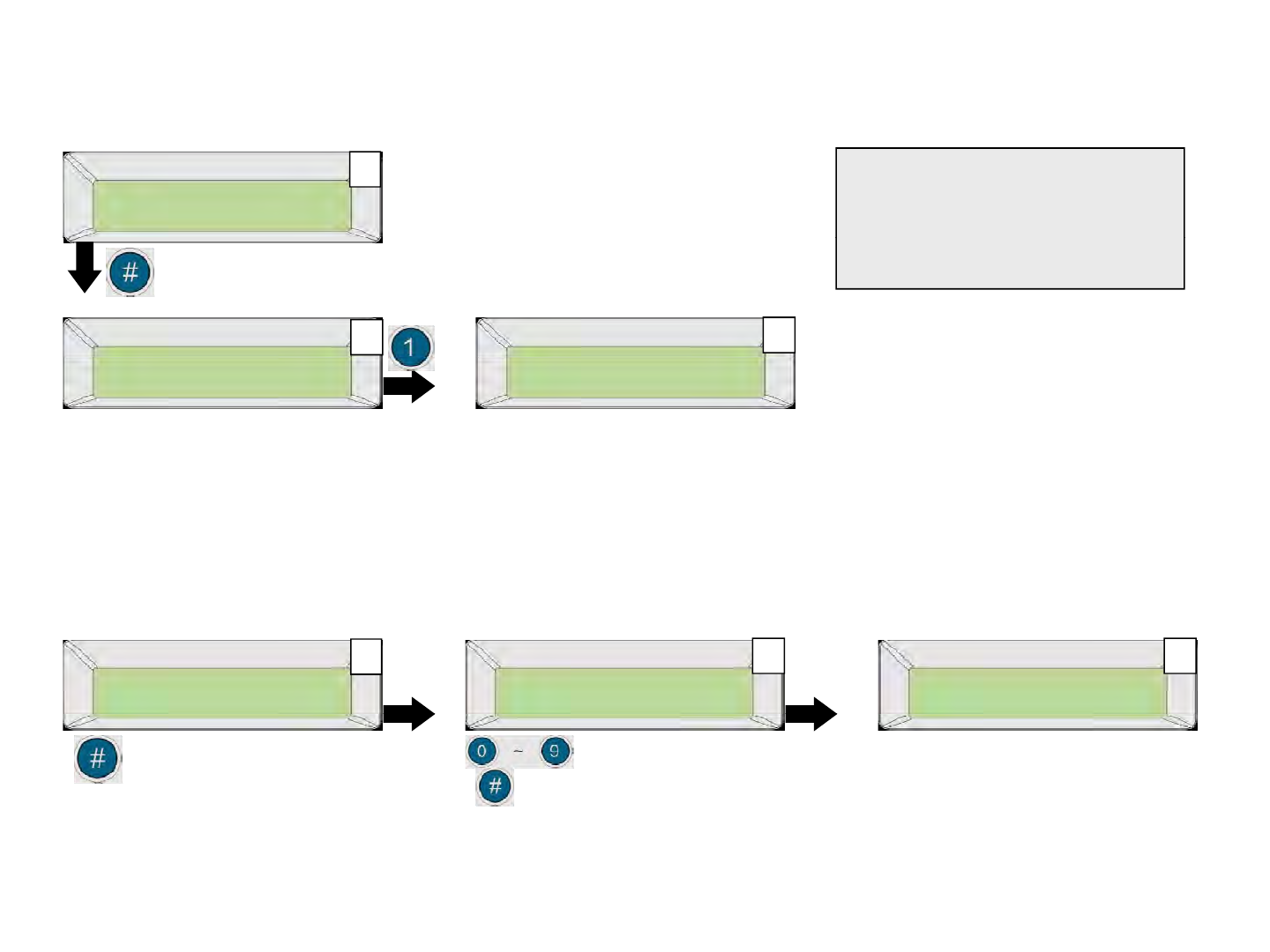
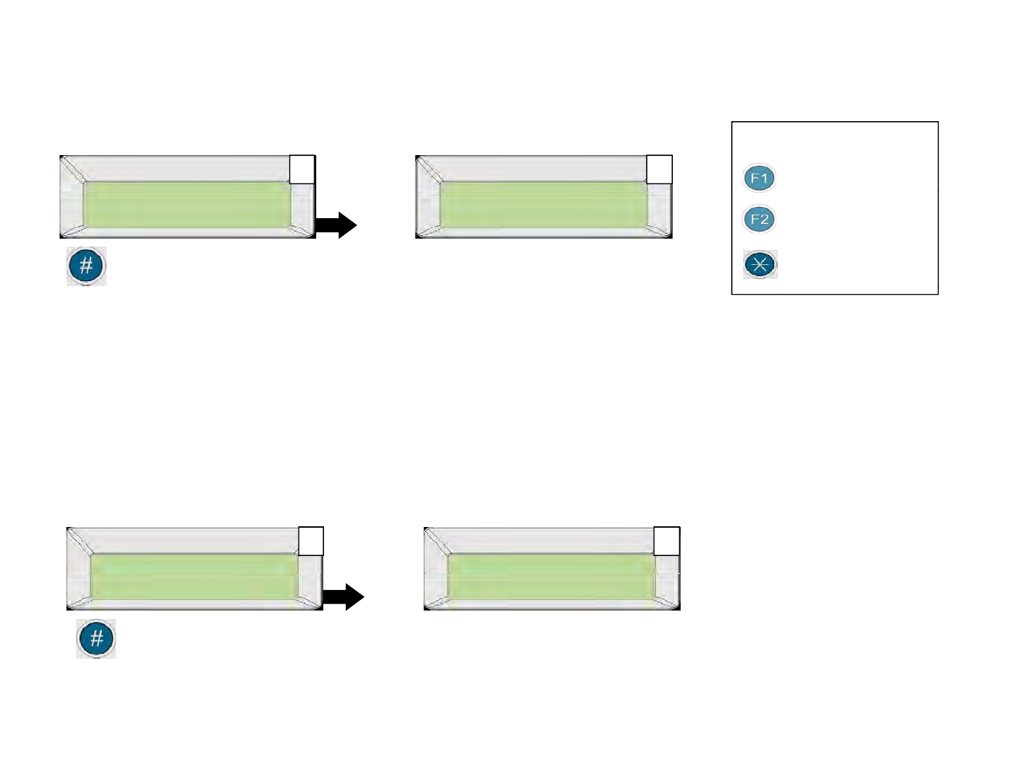
BEGINNING – QUICK START 2 - MENU -
Menu navi
g
ation buttons
1> USER REGIST
2> USER DELETE
3> USER DELETE
4> USER ALLDEL
g
FORWARD
BUTTON
BACK BUTTON
5> USER COUNT
6> USER VIEW
7> USER FP EDIT
8> USER TEMP ID
9> EVENT VIEW
END MENU AND
RETURN TO
BE
G
INNIN
G
EXIT MENU 10> EVENT COUNT
11> EVENT DELETE
12> DOOR RELAY
13> DOOR MODE
14
>
DOOR TIME
[ A N Y M O D E ]
16: 10: 46 [WED]
GG
PROCESS
3
14
DOOR
TIME
15> DOOR ALARM
16> SET COMM ID
17> SET TIME
18> SET CD TYPE
19> SET FG TYPE
[
A N Y M
O
D E
]
1> USER REGIST
1
19>
SET
FG
TYPE
20> SET REACCESS
21> SET CD2 FUN
22> SET ALM FUN
23> SET ANTIPASS
[O]
16: 10: 46 [WED]
Press the ‘*’ sign.
24> SET FIRE
25> SET SECRET 35> TCP/IP DHCP
26> SET LIMIT 36>IP ADDRESS
27> SET DAYLIGHT 37> SUBNET MASK
28> VIEW AT-FUNC 38>GATEWAY
2
VALIDATE ADMIN
ID : 1234 Menu Access
29> VIEW AT-DOOR 39> LANGUAGE
30> VIEW AT-MODE 40> SAVE ENROLL
31> VIEW BELL 41> LOAD ENROLL
32> VIEW T-ZONE 42> SAVE SLOG
33>VIEW NO
FUN 43> SAVE GLOG
4
A
fter entering the Admin ID press the ‘#’
sign.
(If the Admin ID does not exist,
press “1234” to access the menu)
33>VIEW
NO
-
FUN
43>
SAVE
GLOG
34> S/W VERSION 44> EXIT

ADMIN REGISTRATION
1> USER REGIST 1> USER REGIST
1
910
[ANY MODE]
16: 10: 46 [WED]
-----------OK--------- PRESENT USER FP
Press the ‘*’ sign to access
the admin menu.
When the machine accepts the
fingerprint or card correctly the
above will be shown.
To make sure enter one more time.
If its ‘2FP’ enter a different
fingerprint
8
11
1> USER REGIST
PRESENT USER FP
2
The above shows when ‘FP’
(fingerprint) is selected
PRIVILEGE
1: ADMIN 2: USER
Press ‘1’
(1:Admin 2:User)
VALIDATE ADMIN
ID : 1234
8
11
1> USER REGIST
SETTING
COMPLETE
3
After entering “1234” press
the ‘#’ sign the enter the
menu.
(fingerprint)
is
selected
.
When the sensor emits a light
place the finger to be used.
-
(1:Admin
2:User)
1> USER REGIST
7
12
1>
USER
REGIST
Complete
1: 1 FP / 2: 2 FP
NOTE :
Press the ‘#’ sign
to process.
The above shows when ‘FP’ is selected.
-FP 1 : Register 1 fingerprint
-FP 2 : Register 2 fingerprints
41> USER REGIST
FP ID : 1234
Enter fin
g
er
p
rints ID.1~4 di
g
its
)
NOTE
:
- Admin authority is given to a users ID.
Therefore, an Admin’s card or
fingerprint can be reused to a new
user’s ID.
1> USER REGIST
ID : 12345678
6
1> USER REGIST
1: CD 2: FP 3: CD/FP
Enter an ID number to be
used, up to 8 digits and
p
r
ess
t
h
e
‘
#
’
s
i
g
n. Decide which will be used for entrance.
gp g)
5
5
pesst e # sg
1.CD : Card
2.FP : Fingerprint
3.CD/FP : Card and Fingerprint
Press the ‘#’ sign after selection.

CHAPTER 2
CHAPTER
2
- MENU EXPLAINATION-
6

CHAPTER 2 – MENU EXPALINATION
- EXPLAINATION OF EACH OPTION
SYSTEM MENU 1. USER REGIST
1-1> USER/ADMIN CARD REGISTRATION 9
1-2> USER/ADMIN FINGERPRINT REGISTRATION 10
1-3> USER/ADMIN FINGERPRINT
AND CARD REGISTRATION 11
SYSTEM MENU
2 USER VERIFY
SYSTEM MENU 19. SET FG TYPE
19> FINGERPRINT SECURITY LEVEL 26
SYSTEM MENU 20. SET REACCESS
20> SECURITY RECOGNITION SETUP 27
SYSTEM MENU 21. SET CD2 FUN
21> EXTERNAL READER FUNCTION KEY SETUP
27
SYSTEM
MENU
2
.
USER
VERIFY
2> USER/ADMIN VERITY 12
SYSTEM MENU 3. USER DELETE
3> USER/ADMIN DELETE 13
SYSTEM MENU 4. USER ALL DELETE
4> USER/ADMIN ENTIRE DELETE 14
21>
EXTERNAL
READER
FUNCTION
KEY
SETUP
27
SYSTEM MENU 22. SET ALM FUN
22> EXTERNAL ALARM FUNCTION SETUP 28
SYSTEM MENU 23. SET ANTIPASS
23> ANTI-PASS BACK SETUP 29
SYSTEM MENU 24. SET FIRE
SYSTEM MENU 5. USER COUN
T
5> USER/ADMIN REGISTRATION STATUS 15
SYSTEM MENU 6. USER VIEW
6> VIEW REGISTERED USER/ADMIN 15
SYSTEM MENU 7. USER FP EDIT
7
>
EDIT USER/ADMIN FINGERPRINT
16
24> FIRE-SENSOR SETUP 29
SYSTEM MENU 25. SET SECRET
25> ID SECURITY (“*” SIGN) SETUP 30
SYSTEM MENU 26. SET LIMIT
26> SET PROHIBIT TIME 30
SYSTEM MENU
27.
SET DAYLIGHT
7
EDIT
USER/ADMIN
FINGERPRINT
16
SYSTEM MENU 8. USER TEMP ID
8> TEMPORARY USER ID SETUP 17
SYSTEM MENU 9. EVENT VIEW
9> EVENT VIEW 18
SYSTEM MENU 10. EVENT COUNT
10> EVENT COUNT
19
SYSTEM
MENU
27.
SET
DAYLIGHT
27> SETUP CONTROLLER TIME ZONES 31
SYSTEM MENU 28. VIEW AT-FUNC
28> VIEW FUNCTION KEY 32
SYSTEM MENU 29. VIEW AT-DOOR
29> VIEW ALLOWED AUTO DOOR TIME 32
SYSTEM MENU
30 VIEW AT
MODE
10>
EVENT
COUNT
19
SYSTEM MENU 11. EVENT DELETE
11> EVENT DELETE 19
SYSTEM MENU 12. DOOR RELAY
12> Door Relay SETUP 20
SYSTEM MENU 13. DOOR MODE
SYSTEM
MENU
30
.
VIEW
AT
-
MODE
30> VIEW TIME ZONE OPERATION MODES 33
SYSTEM MENU 31. VIEW BELL
31> VIEW BELL TIME ZONE 33
SYSTEM MENU 32. VIEW T-ZONE
32> VIEW SET TIME ZONE 34
13> DOOR MODE SETUP (Card, ID, 지문)20
SYSTEM MENU 14. DOOR TIME
14> LOCK TIME SETUP 22
SYSTEM MENU 15. DOOR ALARM
15> DOOR OPEN ALARM SETUP 22
SYSTEM MENU
16 SET COMM ID
SYSTEM MENU 33. VIEW NO-FUN
33> RELAY NO FUNCTION KEY VIEW 34
SYSTEM MENU 34. S/W VERSION
34> VIEW CONTROLLER VERSION 35
SYSTEMMENU 35,36,37,38 TCP/IP MENU 36
SYSTEMMENU 39 LANGUAGE
37
7
SYSTEM
MENU
16
.
SET
COMM
ID
16> CONTROLLER ADDRESS SETUP 23
SYSTEM MENU 17. SET TIME
17> CONTROLLER TIME SETUP 24
SYSTEM MENU 18. SET CD TYPE
18> CARD OPERATION MODE SETUP 25
SYSTEMMENU
39
.
LANGUAGE
37
39>CONTROLLER LANGUAGE SELECTION
SYSTEMMENU 40,41,42,43 USB MEMORY MENU 38
SYSTEM MENU 44. EXIT
44> EXIT MENU (TO INITIAL SCREEN) 39
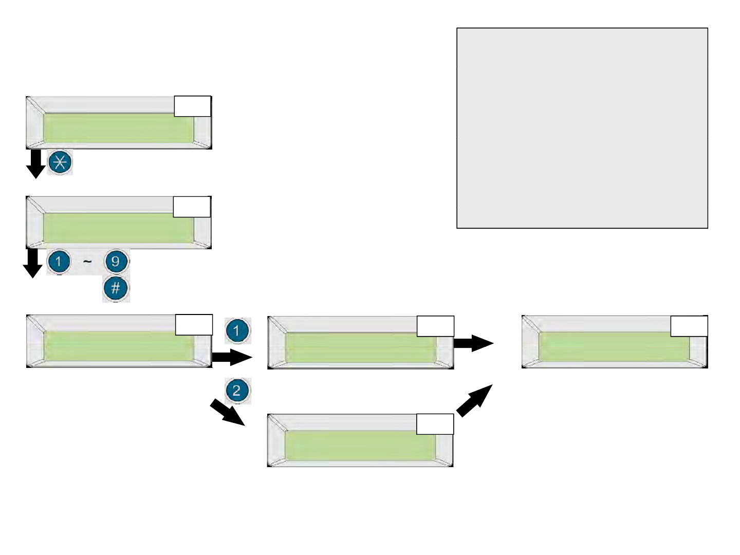
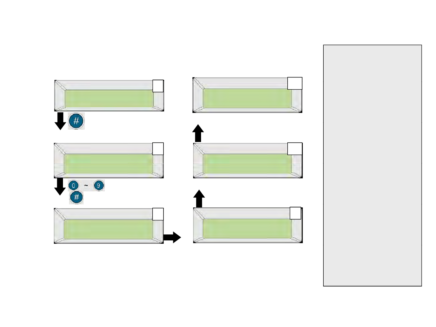
1. SYSTEM MENU ACCESS
(AFTER ADMIN IS
REGISTERED)
NOTE :
Only when the admin is registered (refer
REGISTERED)
[ A N Y M O D E ]
16
:
10
:
46
[WED]
1-1
-
Only
when
the
admin
is
registered
.
(refer
to pg13 for instructions)
-When the admin ID is incorrect, access to
the menu is denied and the screen will
t t th i iti l
16
:
10
:
46
[WED]
1
-
2
The screen above shows
the initial screen.
Press the ‘*’ sign.
re
t
urn
t
o
th
e
i
n
iti
a
l
screen.
-If the admin is not registered, access to
the menu is allowed. It is a good idea to
re
g
ister at least one admin.
VALIDATE ADMIN
ID : 12345678
1
-
2
Enter the admin ID and press
the
‘
#
’
sign.
g
VALIDATE ADMIN 1-3 1-5
the
#
sign.
(the above shows when the
admin ID is ‘12345678’.)
VALIDATE ADMIN
1-4
1. USER REGIST
1:FP 2:CARD
Select what to use when
registering for admin.
1: Fin
g
er
p
rint 2:Card
PRESENT USER FP
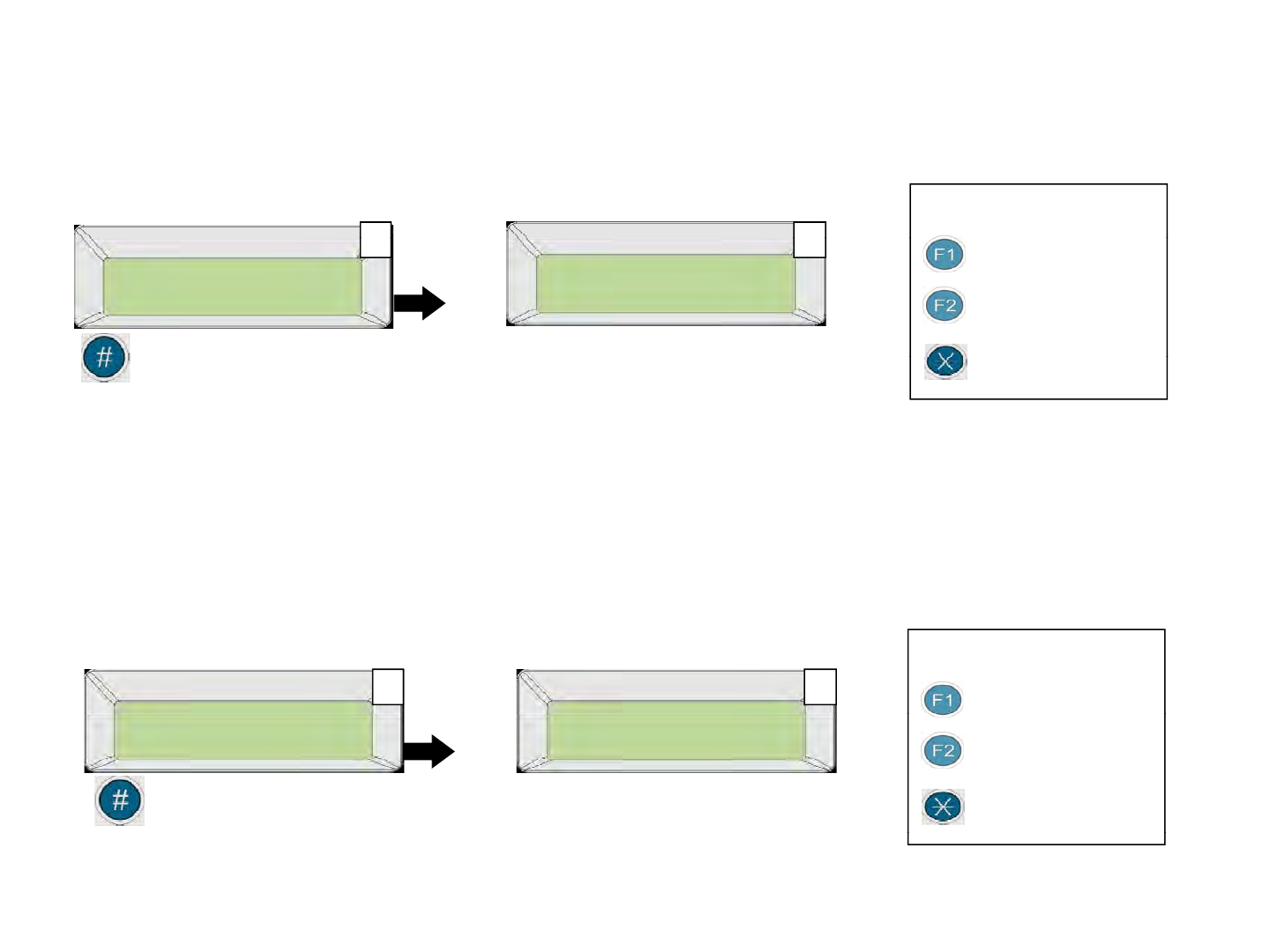
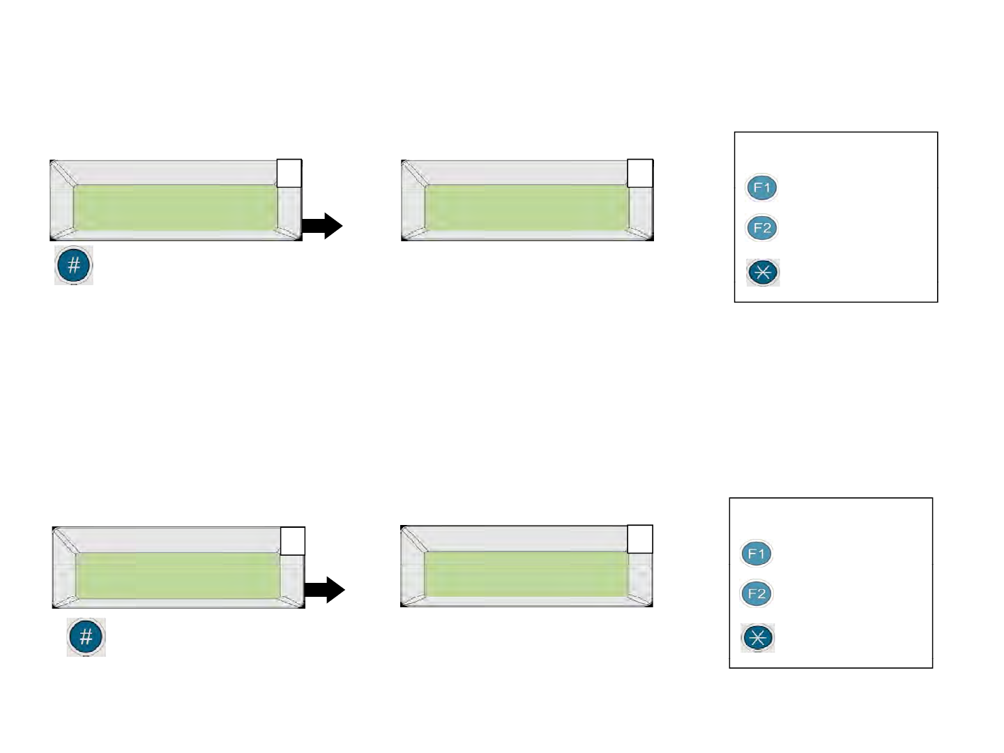
Access to the system menu.
Press F1 and F2 to access a
menu.
Use fingerprint used to
register admin ID.
VALIDATE ADMIN
PRESENT USER CD
1-4
gp
Use card used to register
8
admin ID.
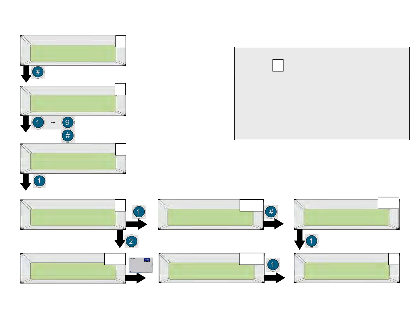
1> USER REGIST
1
1>
1
Press the ‘#’ sign in the 1>
NOTE :
•From the step
1: CD
Register user ID by card
3
USER REGIST
1> USER REGIST
ID : 12345678
2
menu.
1:
CD
–
Register
user
ID
by
card
2: FP – Register user ID by fingerprint
3: C+F – Register user ID by card and fingerprint
WARNING:
Setup the Card Type and Facility Code in
1> USER REGIST
WARNING:
Setup
the
Card
Type
and
Facility
Code
in
the #18 system menu before manually inputting card
numbers into the system.
3
Enter the user ID number that is
to be used for entry and press
the ‘#’ sign.
1>
USER
REGIST
1: CD 2: FP 3: C+F
Press the ‘1’
button.
1: MAN CD ENTRY
2: AUTO CD ENTRY
1: MAN CD ENTRY
NUM :12345678 PRIVILEGE
1: ADMIN 2: USER
4-B
44-A
1: Enter the card number for entry
Manually enter the card
’
s
1: Admin
2: AUTO CD ENTRY PRIVILEGE
1: ADMIN 2: USER
SETTING
COMPLETED
4-2
4-1 5
1:
Enter
the
card
number
for
entry
.
2: Place card onto reader for entry.
Manually
enter
the
card s
number.
1:
Admin
2: User
9
1:
ADMIN
2:
USER
COMPLETED
1: Admin
2: User
Place card onto the reader.
The reader will automatically
register onto the system.
User card registration is
complete.
NOTE :
Ui t fi it (2FP)i t d
1-2>USER REGIST
1
-
U
s
i
ng
t
wo
fi
ngerpr
i
n
t
s
(2FP)
i
ns
t
ea
d
of one (1FP) makes it more easy for
the system to recognize users.
-One fingerprint is placed on the
1> USER REGIST
1
Press the ‘#’ in the 1> menu.
sensor three times to complete
registration.
4-C
1> USER REGIST
SETTING
COMPLETED
1> USER REGIST
ID : 12345678
2
User fingerprint
6
5
PRESENT USER FP
PRIVILEIGE
1: ADMIN 2: USER
1>
USER REGIST
3
User
fingerprint
registration complete
When the red sensor light
appears place the same
finger on the sensor.
Enter the user ID used
for entry and press the
‘#’ sign.
4-B
1> USER REGIST
---------OK-----------
1:
ADMIN
2:
USER
1>
USER
REGIST
1: CD 2: FP 3: C+F
Press ‘2’.
When correctly done, the
1: ADMIN – Setup as Admin
2: USER – To setup as user
press ‘2’
4-A
44-3
1> USER REGIST
FP ID : 1234 1> USER REGIST
PRESENT USER FP
1> USER REGIST
PRESENT USER FP
Enter the fingerprint ID (1
above is shown
When the red sensor
54-2
1> USER REGIST 1> ENROLL USER
Enter
the
fingerprint
ID
(1
~ 4 digits) When the red sensor light
appears place the finger to be
used for entry on the sensor.
light appears, place a
different fingerprint.
10
4-1
1:1FP / 2: 2FP
1> ENROLL USER
PRESENT USER FP
---------O
K
-----------
1:1FP – Register one fingerprint
2:2FP – Register two fingerprints
When correctly done, the
above is shown.
1
1-3>USER REGIST
NOTE :
-
When registering a fingerprint please refer to
1> USER REGIST
Press the ‘#’ sign at 1>
When
registering
a
fingerprint
,
please
refer
to
‘how to use your fingerprint’ chapter.
1> USER REGIST
ID : 12345678
27-1
1> USER REGIST
PRESENT USER FP
7-2
1> USER REGIST
---------OK-----------
When the light from the sensor
Wh d l th
1>
USER REGIST
37
1>
USER REGIST
7-3
1>
USER REGIST
Enter the user ID
that is used for
entry
When
the
light
from
the
sensor
turns on you may place your
fingerprint used for entry
Wh
en
d
one proper
l
y
th
e
above will be shown
1>
USER
REGIST
1: CD 2: FP 3: C+F
4
6
1>
USER
REGIST
1:1FP / 2: 2FP
1>
USER
REGIST
PRESENT USER FP
Press ‘3’ 1:1FP – Register one fingerprint
2:2FP – Register two fingerprints When the sensor light is on
place the same fingerprint on
the sensor.
4
1> USER REGIST
FP ID : 1234
6
1> USER REGIST
FP ID : 1234
8
PRIVILEGE
1: ADMIN 2: USER
Enter a fin
g
erprint ID. Enter fin
g
er
p
rint ID
the
sensor.
1: ADMIN
–
Set as admin
p
ress
1: MAN CD ENTRY
2: AUTO CD ENTRY
5
2: AUTO CD ENTRY
5-1
SETTING
(1 ~ 4 digits)
gp
(up to 4 digits)
p
‘1’ or…
2: USER – Set as user press ‘2’
9
11
2:
AUTO
CD
ENTRY
SETTING
COMPLETED
1: Enter the number found in the
back of the card or…
2: Place card at the reader
Place card used for
entry on the reader. Fingerprint registration
complete
2> USER VERIFY
Use Fingerprint and Card to verify registered USER/ADMIN ID
Use
Fingerprint
and
Card
to
verify
registered
USER/ADMIN
ID
.
2> USER VERIFY
1NOTE :
-When checking fingerprints refer to the ‘How
to use your fingerprint’
Press the “#”at the 2>
menu.
-The below menu 2 : FINGER applies to the
KF-2000 and FPC-301 only.
2> USER VERIFY
ID
12345678
A
2> USER VERIFY
1: FINGER 2: CARD
To verify using fingerprint
press
‘
1
’
2
A : Admin
U : User
Card or
fingerprint ID
ID
:
12345678
A
press
1
To verify using card press
‘2’
2> USER VERIFY 2> USER VERIFY
2-1 2-2
PRESENT USER FP
When the sensor light is
on place the same
fingerprint on the scanner
PRESENT USER CD
Place card on the reader.
2>USER VERIFY
ID : 12345678 A
Example: ID is 12345678 and
3
12
Example:
ID
is
12345678
and
status is Admin.
(A: Admin U: User)
3> USER DELETE
When deleting registered user/admin ID, that ID will no longer have authorization
NOTE :
3> USER DELETE
1
Press the ‘#’ sign at 3>
3> USER DELETE
ID : 12345678
NOTE
:
- When deleting an ID, all
fingerprint ID and card information
connected with the ID will be
deleted.
2
-When deleting an ID all events
that happened before deletion will
NOT be deleted.
Enter the ID that you wish to delete.
(up to 8 digits) Press the ‘#’ sign.
3> USER DELETE
1: DEL 2:CANCEL
3
3> USER DELETE
4 5
1:DEL
–
delete
2:CANCEL- cancel delete
3> USER DELETE
3>
USER
DELETE
PLEASE WAIT
Processing ID delete… Delete complete
3>
USER
DELETE
13
4> USER DELETE (delete all users)
4> USER DELETE
1
NOTE :
2
Press the ‘#’ sign at 4> -When deleting all users, the admin will also be
deleted.
Press “1”
4> USER DELETE
1: YES 2: CANCEL
All user delete processing
3
SETTING
COMPLETED
4
All
user
delete
processing
4> USER DELETE
All user delete complete
14
5> USER COUNT (registered user/admin status view)
You can view the number of card or fingerprint ID’s registered to the controller.
5> USER COUNT
1
Press the
‘
#
’
at 5>
NOTE :
-Total number of users include the admin.
USER : 00123
FINGER: 00099
2
Press
the
#
at
5>
.
User (including admin) currently
registered is 123. Fingerprint user
amount is 99.
6> USER VIEW (view user/admin registered info.)
View user/admin registered info currently registered on the controller.
6> USER VIEW Order
User/Admin ID
User(U)/Admin(A)
List navigation
buttons
Back
1
Press the ‘#’ sign at 6>
0001 12345678 A
0001 12345678 A
FP:0001 TZ:01,02
Forward
Exit
2
15
FP: 0001 TZ:01,02
Order :0001 User ID : 12345678A (Admin)
Fingerprint ID : 0001 Time zone : 01, 02 time zone
Fingerprint(FP)/Card
(CD) ID Timezone
1,2 setup
Exit
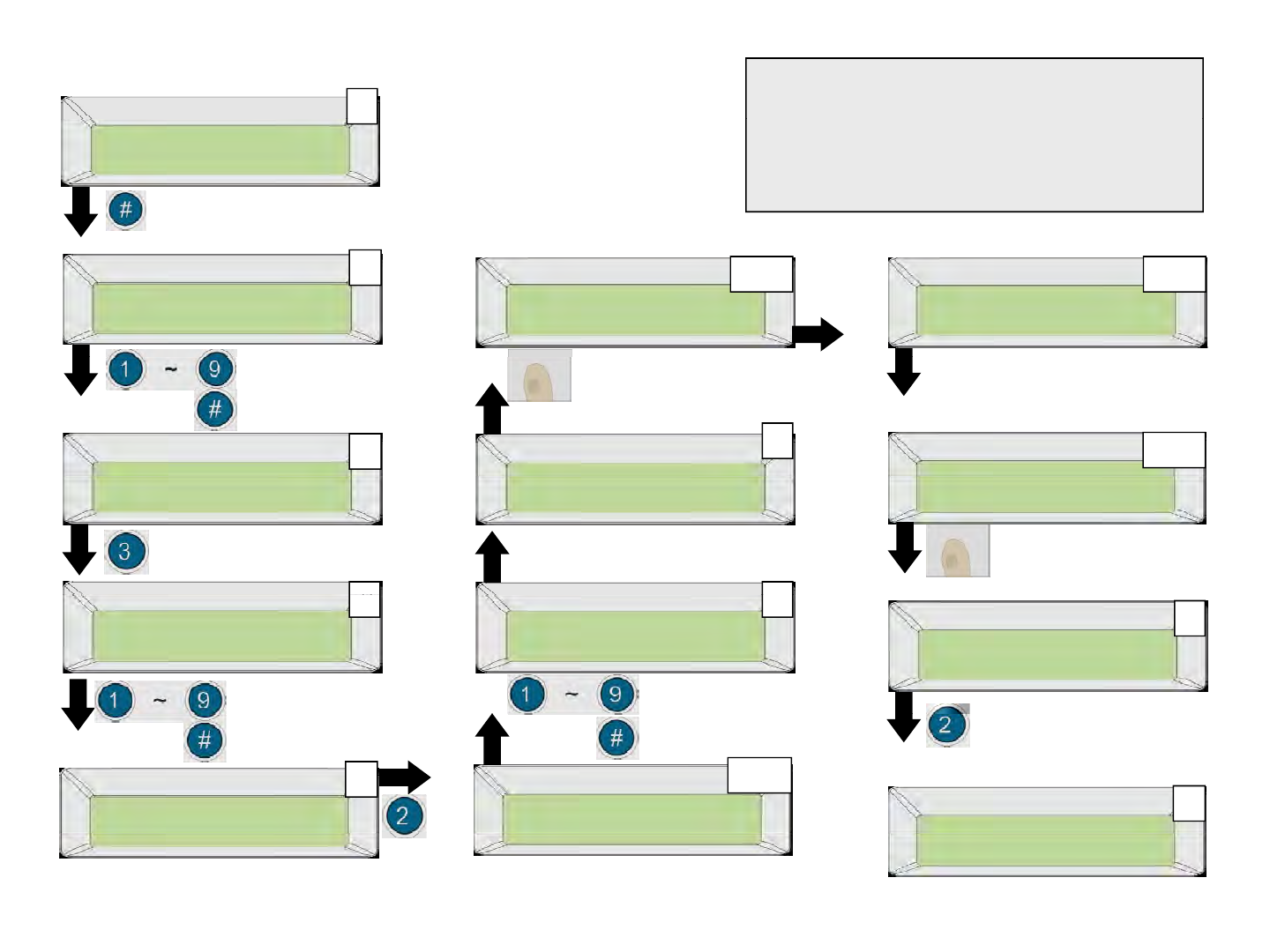
7> USER FP EDIT (Change user/admin fingerprint)
Used to change user/admin fingerprint. This will not change the user/admin ID.
1 5 NOTE :
7> USER FP EDIT
Press the ‘#’ sign at 7>
7> USER FP EDIT
PRESENT YOUR FP
Place the fingerprint to
replace the old
- Refer to the ‘how to use your
fingerprint’secton.
7> USER FP EDIT
ID : 12345678
26
7> USER FP EDIT
--------OK------------
3
Enter the user ID that you
wish to change and press
the ‘#’ sign
Fingerprint input complete
7
7> OPER.. MODE
1 : YES 2: CANCEL
Select ‘1’
7> USER FP EDIT
PRESENT YOUR FP
Place your fingerprint again
for verification
7> USER FP EDIT
1: 1FP / 2: 2FP
4
SETTING
COMPLETED
8
16
1FP: Change one fingerprint
2FP: Change two fingerprints Fingerprint input complete
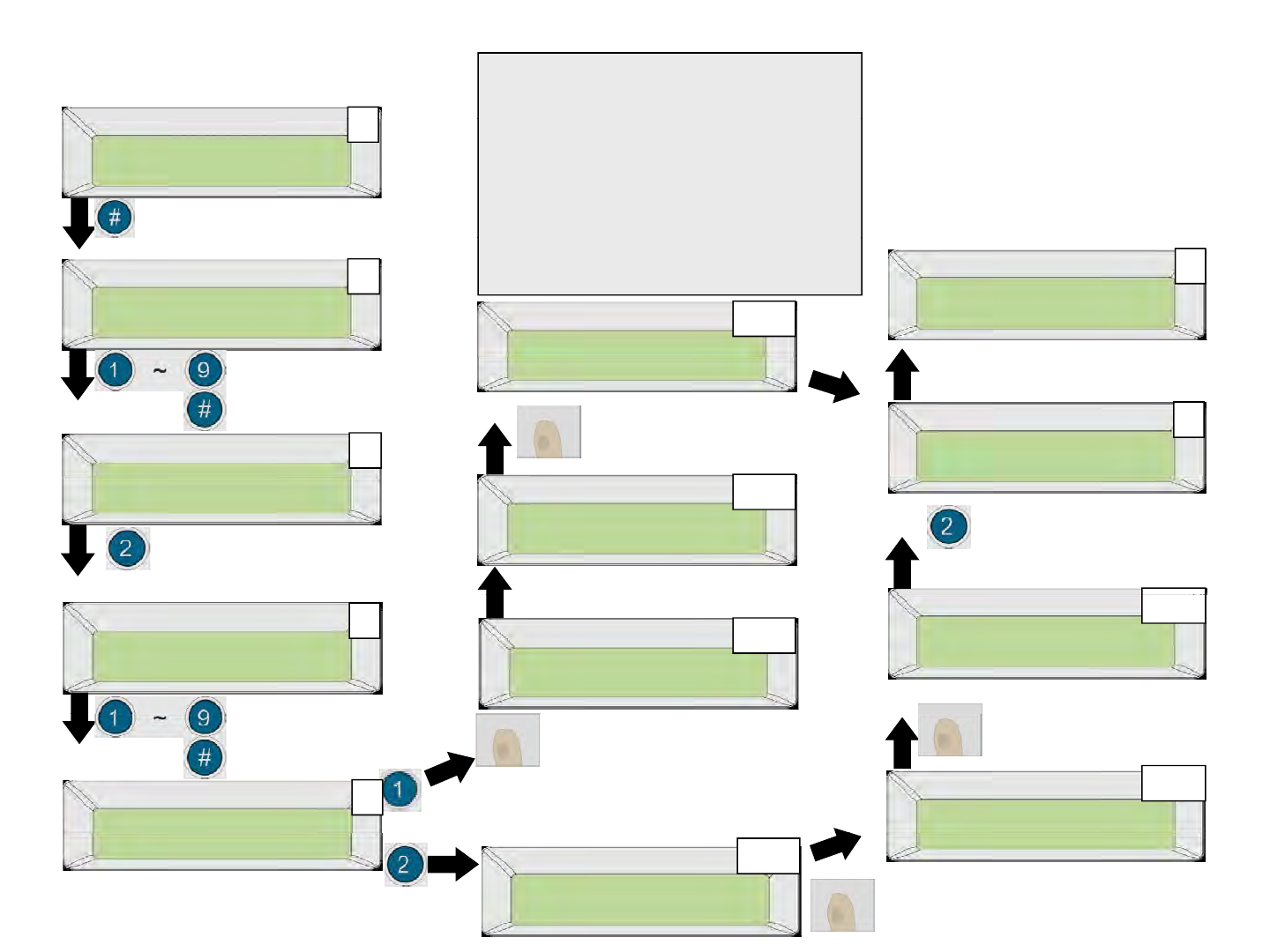
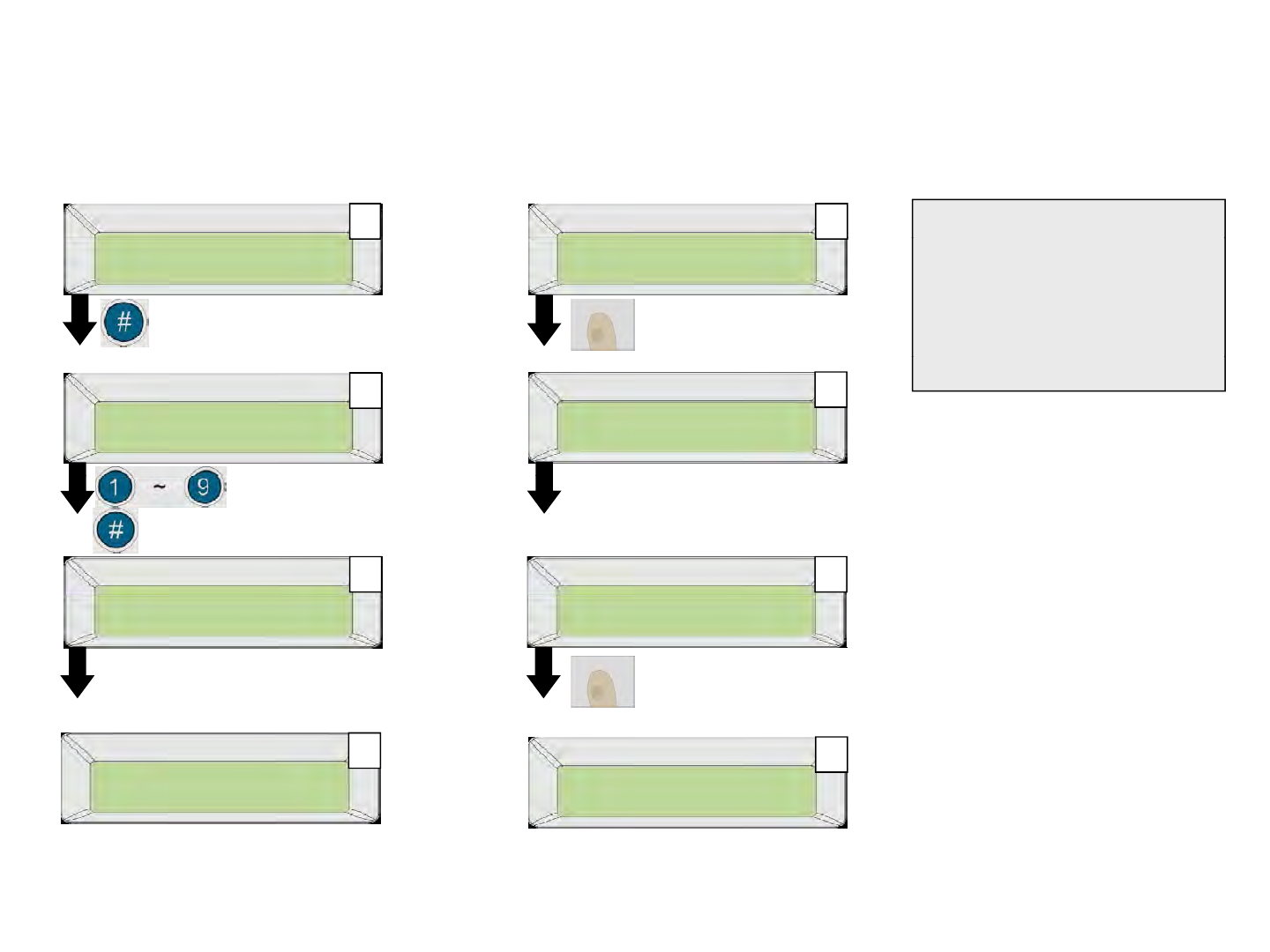
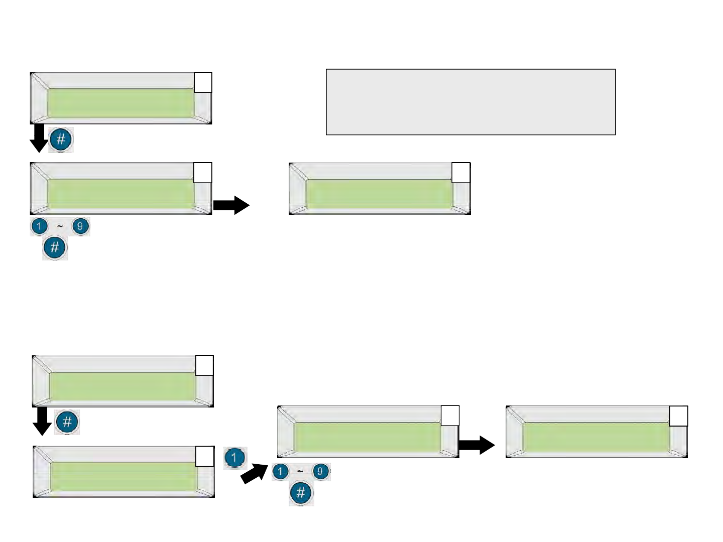
8> USER TEMPORARY ID
When a temporary user needs to enter, but doesn’t need to register (Ex. visitor, guest)
NOTE :
1 4
8> USER TEMP ID
Press the ‘#’ sign at 8>
SETTING
COMPLETED
Temporary ID complete
-Cannot register temporary ID as
admin.
-
Cannot register temporary ID with
8> USER TEMP ID
ID : 12345678 8> USER TEMP ID
TIME [1 - 9] : 3
Cannot
register
temporary
ID
with
fingerprint.
-When properly registered the
following is shown:
WELCOME [F0
0]
23
Enter a temporary ID number
(up to 8 digits) and press the
“#” sign.
Enter the amount the temporary
user is allowed to enter and
press the “#” sign. (minimum 1,
maximum 9)
WELCOME
[F0
-
0]
ID: 12345678 T
(T : Temporary)
-The admin can set the amount of
entries of a temporary ID.(1-9)
-When the amount of entries are used,
the Admin is able to add more entries
allowed for the tem
p
orar
y
ID.
py
-Events are recorded the same way as
regular user ID.
Cannot register temporary ID from
17
-
Cannot
register
temporary
ID
from
regular user ID.
9> EVENT VIEW
View user ID time of entry, date, access authorization, system authorization.
9> EVENT VIEW
NOTE :
1
Press ‘#’ at the screen above.
NOTE
:
EVENT OVERVIEW
- MASTER MENU IN : Access Admin menu
MENU MODE EXIT E it Ad i
2
1. SLOG 2. GLOG -
MENU
MODE
EXIT
:
E
x
it
Ad
m
i
n menu
- MASTER MENU FAIL : Admin menu Access failed
- 12345678 [GRANTED] : ID/fingerprint 12345678 entry
- 12345678 [DENIED] : ID 12345678 Access failed
- USER FG REG : Re
g
ister user fin
g
er
p
rint
1. SLOG : Access Event
2. GLOG: Exit Event
ggp
- USER CD REG : Register user Card
- FINGER DOWNLOAD : Download fingerprint
- CARD DOWNLOAD : Download card
- NONE : No event
0001 : 09/06 15:09
MASTER MENU IN
3
9> EVENT VIEW MENU NAVIGATION
BUTTONS
NEXT EVENT
4
4
The example above shows
that the admin accessed the
admin menu at 9/6 at 15:09.
0002 :
[NONE]
To exit press ‘*’ when the
NEXT
EVENT
BACK EVENT
4
18
screen above appears.
(The example above shows
no event.)
EXIT
10> EVENT COUNT
10> EVENT COUNT
Pres
‘
#
’
when the above appears
1
Pres
#
when
the
above
appears
.
10> EVENT COUNT 2
00012/00012
In this screen the user may know the
quantity of events.
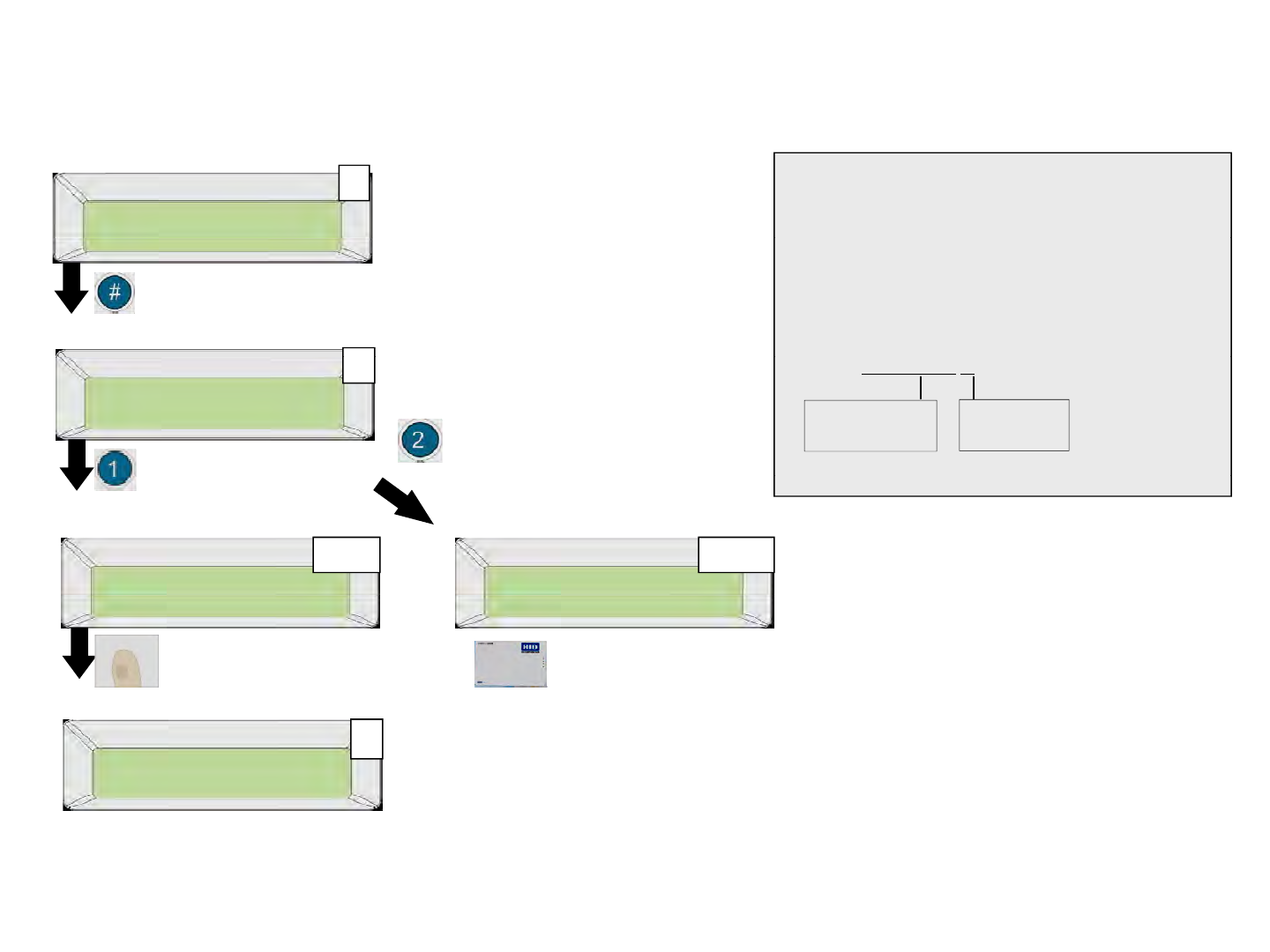
11> EVENT DELETE
NOTE :
11> EVENT DELETE
NOTE
:
-All events will be deleted.
1
Press ‘#’ when the above appears.
11> EVENT DELETE SETTING
23
19
1: YES 2: CANCEL COMPLETED
Event delete complete.
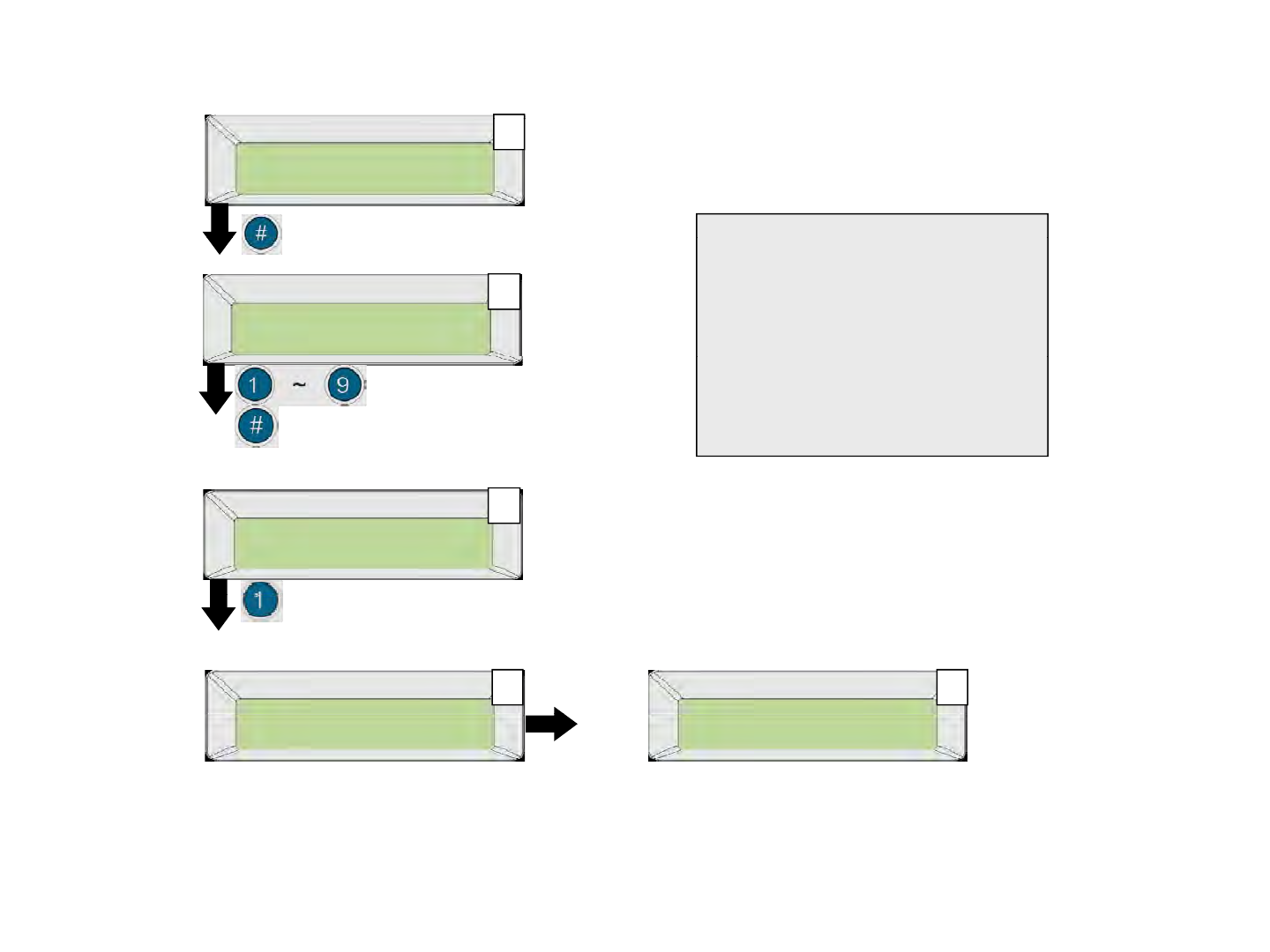
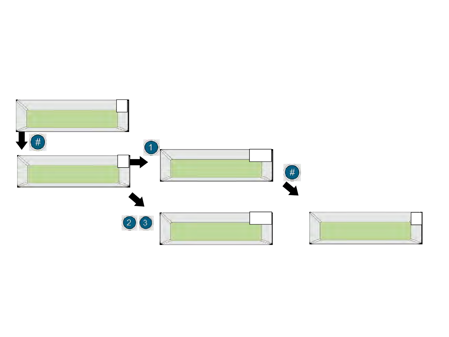
12> DOOR RELAY
This menu is for changing the functions of Relay 1 and 2. Normally Relay 1 controls the door.
In cases where Relay 1 cannot be used, the user can change and use Relay 2 to control the door.
12> DOOR RELAY 1
Press the ‘#’ sign at 12>
3
2
12> DOOR RELAY
1 : RLY 2 : RLY [1]
When Relay 1 is controlling “Door
Control”
To change to Relay 2,
Press “2”
SETTING
COMPLETED
Relay setup complete
3
2
Control”
Press
“2”
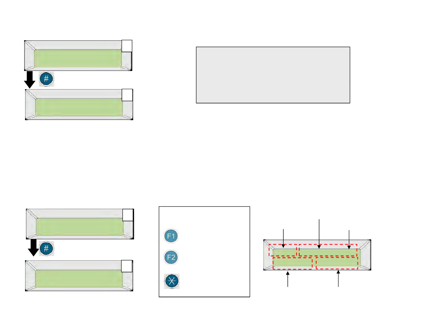
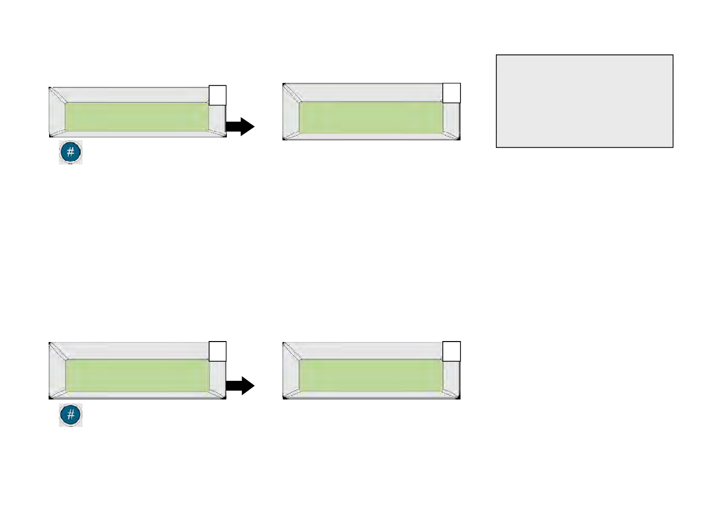
13> DOOR MODE
In this menu the user is allowed to setup door modes according to certain situations. There are a total of 15 ways.
This page only shows how to setup.
13
>
DOOR MODE
List navigation menu NOTE :
1
13
DOOR
MODE
Press the ‘#’ sign at 13>
forward
back
- When accessing the menu, the
current mode used will be shown.
Press “F1” to change to a different
mode and press the
”
#
”
sign
t
20
13> DOOR MODE
[ ID or FP ] exit
mode
and
press
the
#
sign
se
t
up
2
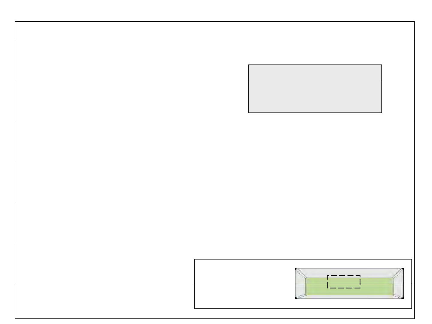
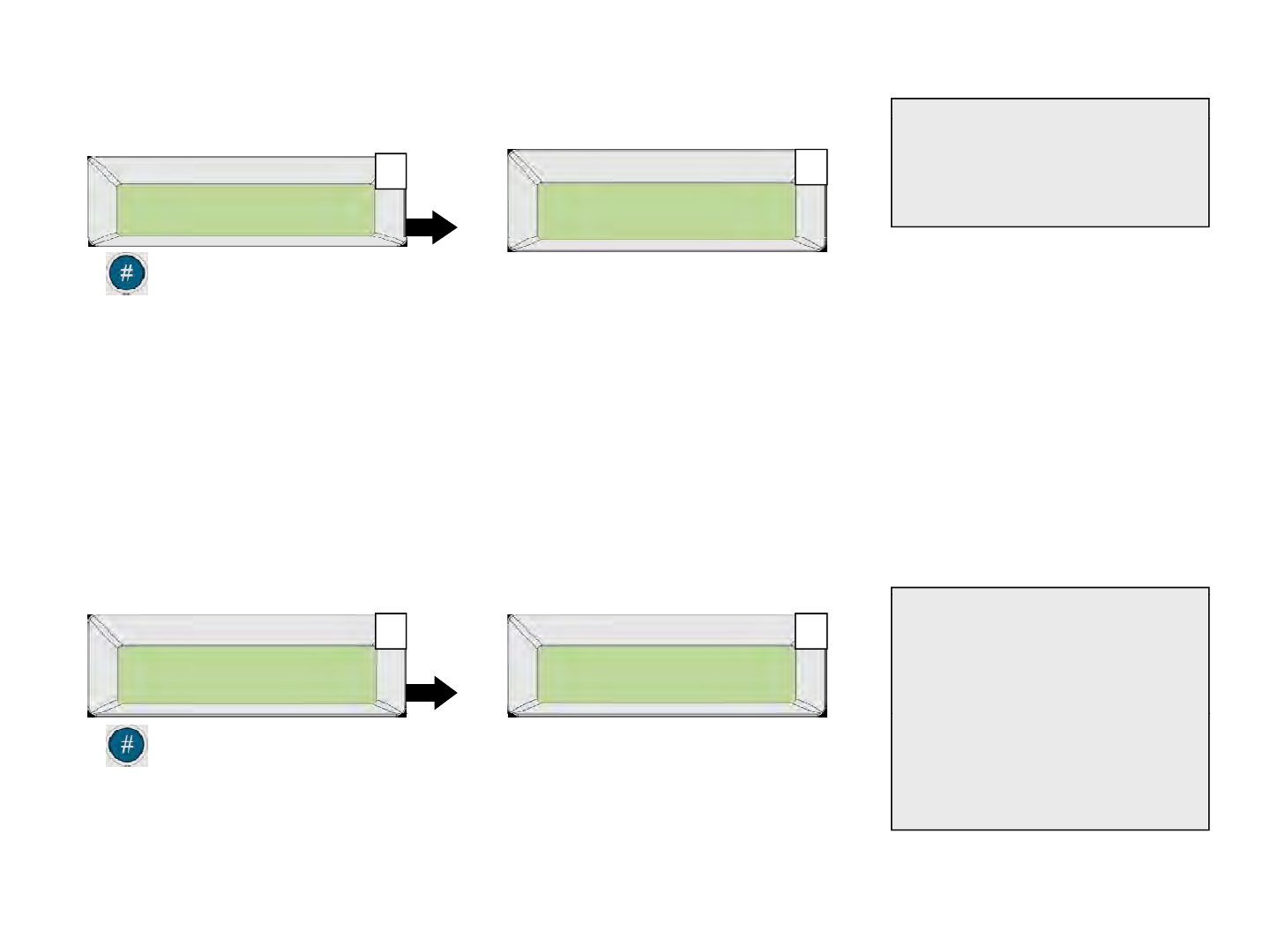
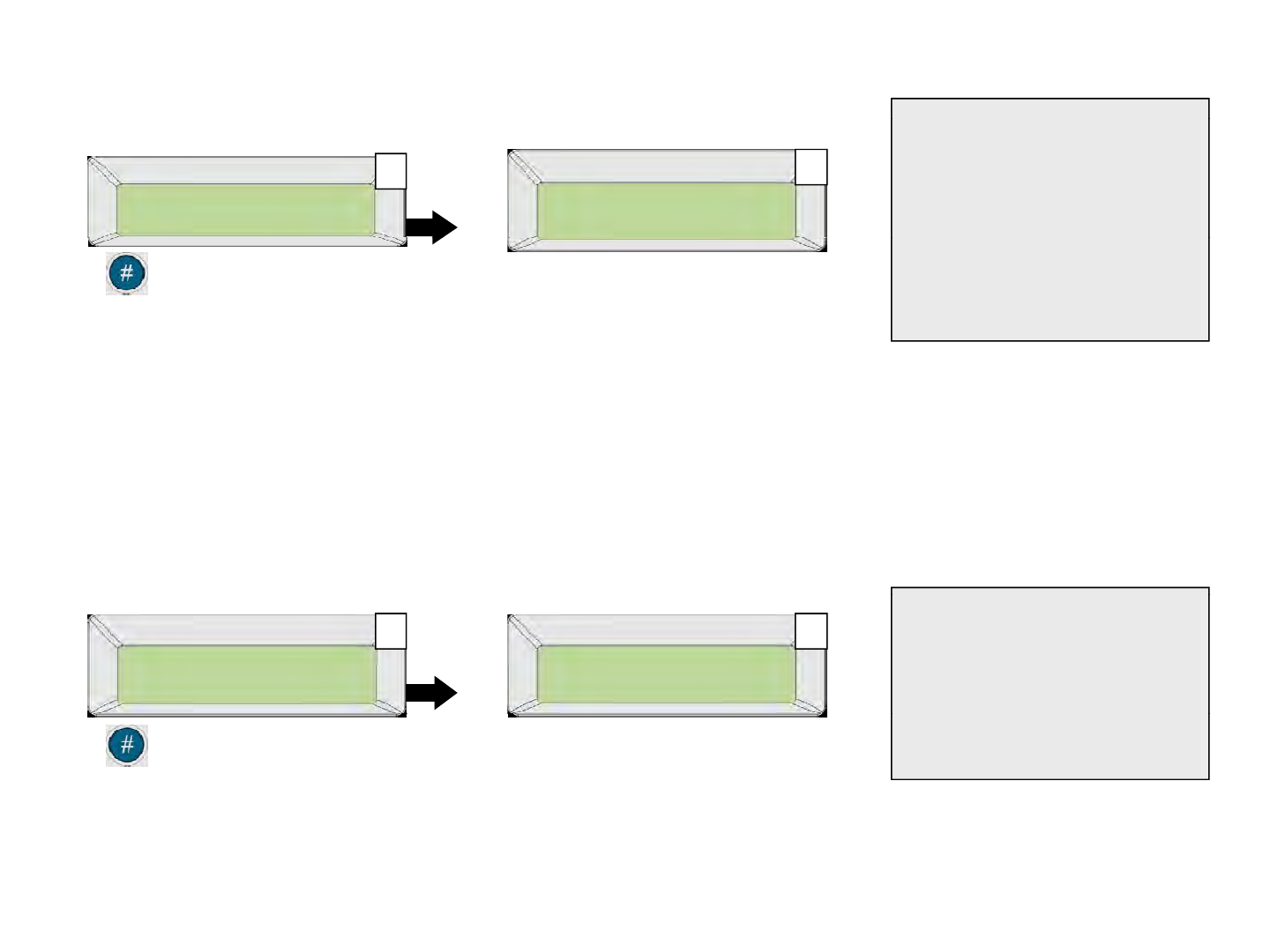
13-1> DOOR MODE (detailed auto door mode instructions)
[Open] : Always Open (Fail-Safe Mode)
[Close] : Always Closed (Fail-Secure Mode) – no access with any form of authorization
[FINGER] : Fingerprint Only – no access with ID or card
[CD] : Card Only – no access with ID or fingerprint NOTE :
[ID or FP] : ID or Fingerprint Only – no access with card
[ID or CD] : ID or Card Only – no access with fingerprint
[
CD or FP
]
: Card or Fin
g
er
p
rint Onl
y
–
no access with ID
-For fingerprint disabled personnel,
any mode of ID entrance is allowed,
except for [CLOSE] mode.
[] gpy
[Any Mode]: Any Form of Authorization - access granted with any form of authorization
[ID and FP]: Both ID and Fingerprint Required for Access – must punch in ID before fingerprint authentication
[ID and CD]: Both ID and Card Required for Access
must punch in ID before Card authentication
[ID
and
CD]:
Both
ID
and
Card
Required
for
Access
–
must
punch
in
ID
before
Card
authentication
[CD and FP]: Both Card and Fingerprint Required for Access – card must be authorized before fingerprint authentication
[ID&FP]or[CD&FP] : both ID and Fingerprint or both Card and Fingerprint are required for Access
[ID&FP]or[CD] : both ID and Fingerprint or just Card are required for Access
[ID&FP]or[ID&CD] : both ID and Fingerprint or both ID and Card are required for Access
[ID & CD & FP]: all three forms needed for access
[CD]
NOTE :
The operation mode described
above is shown in the
g
ra
p
hic
21
[
CD
]
16: 10: 46 [WED]
gp
on the right located in the
dotted square
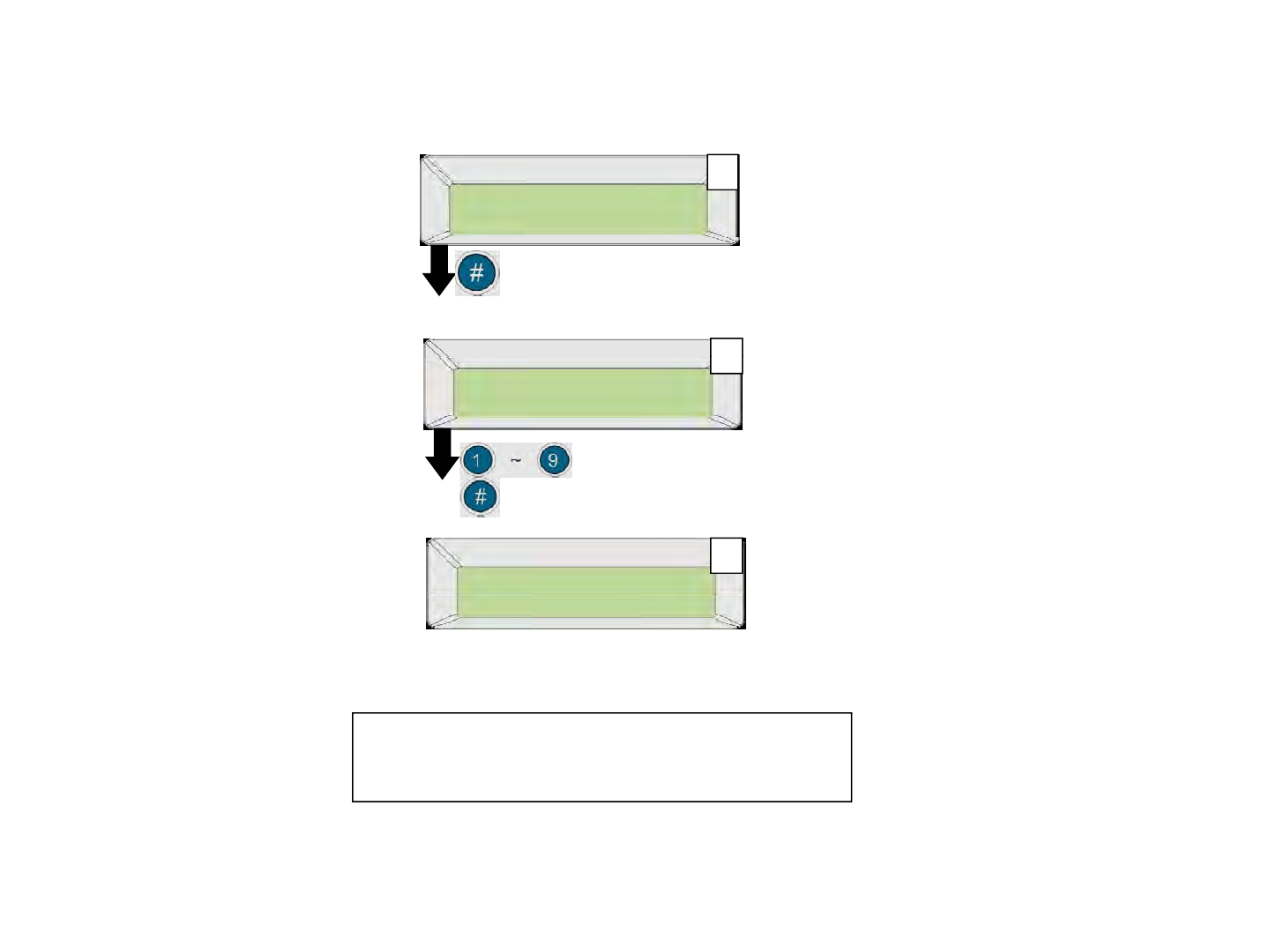
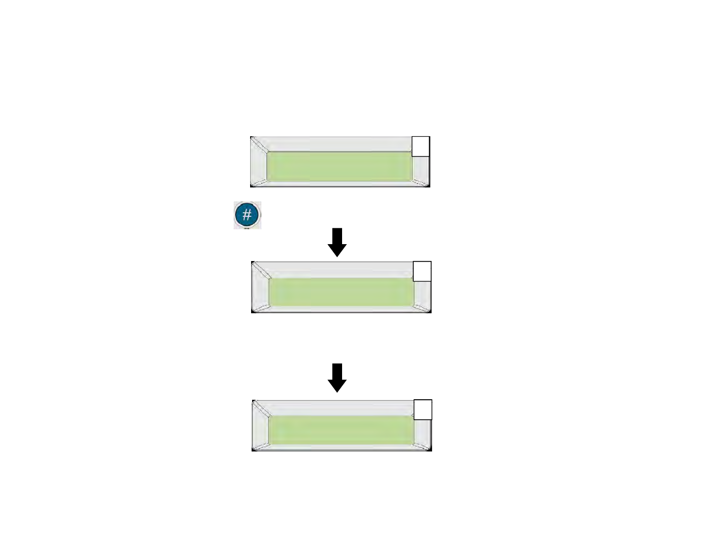
14> DOOR TIME
This menu is for setting the time when the lock device locks again after unlocking.
14> DOOR TIME
Press the
‘
#
’
sign when the
NOTE :
-The default door time is 3 seconds.
1
Press
the
#
sign
when
the
above appears.
14> DOOR TIME
03 TIME
=
05 sec
SETTING
COMPLETED
2 3
03
TIME
05
sec
Able to setup a maximum of 99
seconds.
Aft i t th “#” i
COMPLETED
Locking time setup complete
Aft
er
i
npu
t
press
th
e
“#”
s
i
gn.
15> DOOR ALARM (DOOR open ring)
This menu if to setup an alarm (ring) when a user fails to close the door after entry or exit. When this happens the alarm will
be activated after a user set time (1-99 seconds). The alarm will deactivate after the door closes properly.
15> DOOR ALARM 1
At the screen above, press
the ‘#’ sign.
15> DOOR ALARM
15> DOOR ALARM
03 TIME= 05 sec SETTING
COMPLETED
2
34
22
1 : SETUP 2 : NO
To setup press “1”
If you do not want this option press “2”
Delay time can be setup up to 99
seconds. Press
The “#” sign after completion.
Door Alarm complete.
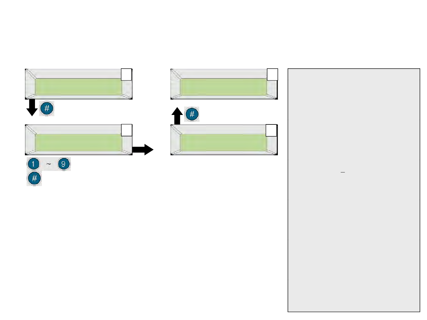
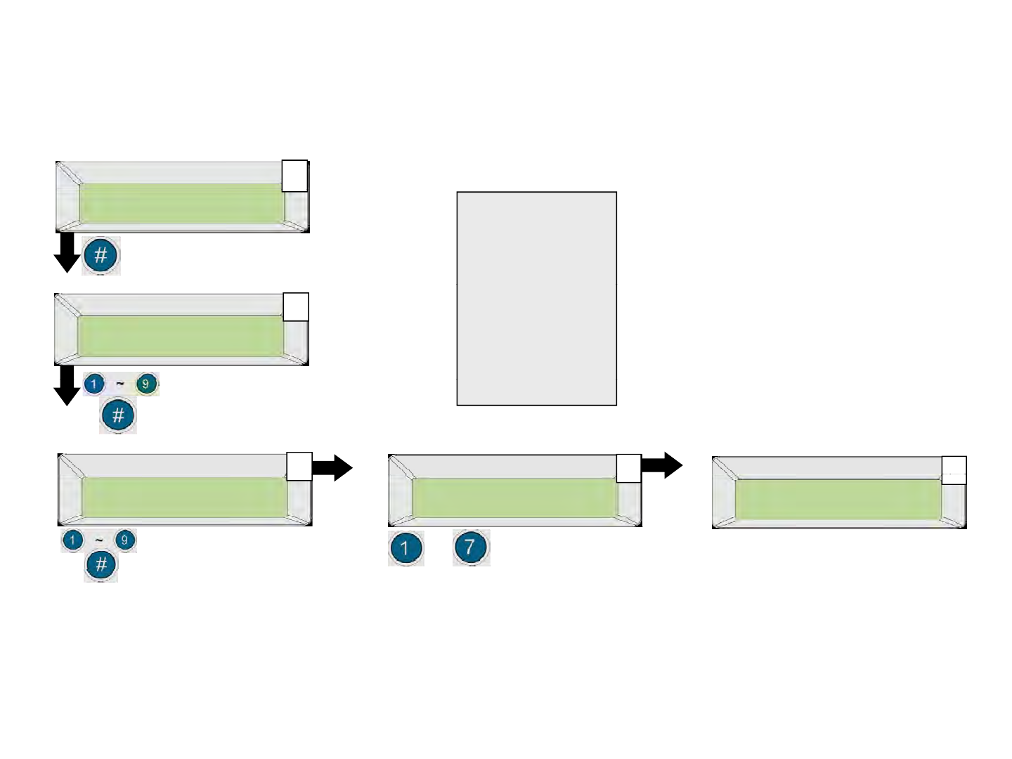
16> SET COMM ID (controller address setup)
When networking several controllers to a computer, each controller needs its own unique address. This menu is to designate
controllers a unique address or edit/change an existing address. (users are recommended to seek advice)
16> SET COMM ID 1
Press ‘#’ when the above is
shown.
2
16> SET COMM ID
[01] 1-16 = 02
2
Choose between 1~16 that will
be the address and press “#”.
SETTING
3
COMPLETED
Address setup complete
-
SF
-
3000 can each have address from 1
-
16
Users must designate an address to each product that is
connected. If the S/W is installed to the computer, it can be
done from there.
23
SF
-
3000
can
each
have
address
from
1
-
16
-The factory default setting is ‘1’. For more details refer to the ‘installers instruction
manual’
17> SET TIME (controller time setup)
The internal clock is used to save the time setup for an event. The internal clock must be exact.
S
1
17>
S
ET TIME NOTE :
Sunday – 1
Monday – 2
Td
3
Press the ‘#’ sign when the
above is shown.
YEAR:MON:DAY
05 : 09: 11
T
ues
d
ay
–
3
Wednesday – 4
Thursday - 5
Friday – 6
Saturday - 7
2
4
5
Enter by order year, month,
date and skip by pressing the
‘#’ sign.
3
HOUR:MIN:SEC
10 : 11: 26 S M T W T F S
1 2 3 4 5 6 7 SETTING
COMPLETED
5
First input the hour, minute
dddth‘#’
~Time setu
p
com
p
lete
an
d
secon
d
an
d
press
th
e
‘#’
sign Select the day by pressing
the number that corresponds
to the day
pp
24
18> SET CD TYPE (Wiegand type setup)
This menu provides information on how to setup cards used for entry. This chapter will teach you how to register your card
and change your card type
and
change
your
card
type
.
18> SET CD TYPE
1
18 SET CD TYPE
FACILITY CODE
23
Press ‘#’ at 18>
18
>
SET
CD
TYPE
1:26 2:34 3:37 0-255 :
1:26 – 26bit wiegand card
(HID, EM, INDALA)
2:34
–
34bit wiegand card (MIFARE)
Enter a secure code with the
number buttons from ‘0’ to ‘255’
SETTING
COMPLETED
SETTING
COMPLETED
4
3
2:34
–
34bit
wiegand
card
(MIFARE)
3:37 – 37bit wiegand card (KEICO)
Card type setup complete
’
Card type setup complete
Card
type
setup
complete
Card
type
setup
complete
25
19> BRIGHT ADJ (fingerprint sensor brightness setup)
19> BRIGHT ADJ
1
2
Press ‘#’ when the above menu is
shown
19> SET FG TYPE
1 : LEVEL 2 : AUTO
2
A
djusting the brightness
SETTING
COMPLETED
Fingerprint sensor brightness
4
26
Fingerprint
sensor
brightness
setup complete
20> SET REACCESS (authorization security setup)
This function was created to decrease the troublesome situations of using a card again after a fingerprint is read as
an error when a fingerprint scan is required after a card scan
an
error
when
a
fingerprint
scan
is
required
after
a
card
scan
.
20> SET REACCESS
NOTE :
- If an admin is registered by a fingerprint,
1
Press the ‘#’ sign at 20>
authorization security is not in effect when
accessing the system menu.
2
20> SET REACCESS
[ 3 ] 0-9 : 5
Enter the amount of times a
re-scans allowed. Press the
SETTING
COMPLETED
Authorization security setup
2
3
“#” sign after setup.
(maximum : 10)
Authorization
security
setup
complete
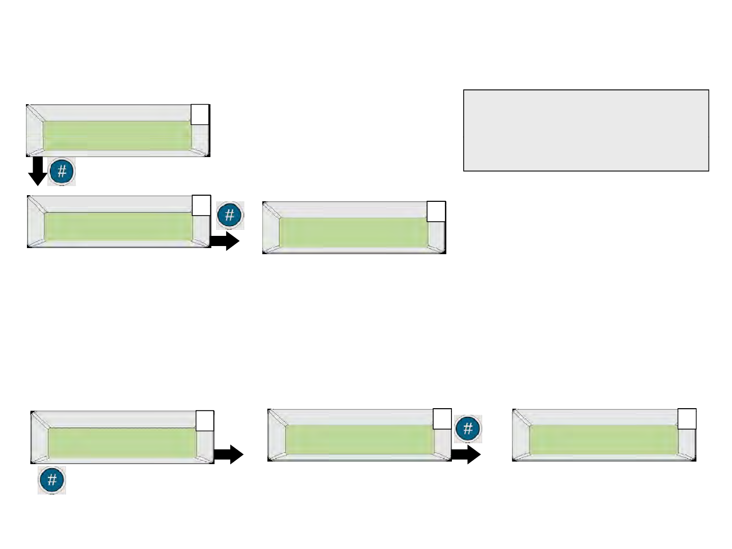
21> SET CD2 FUN (external reader function key)
If a controller is connected to a reader, this function gives a function key to the external reader automatically, thus a an
automatically setup function key is given to a user who is authorized from an external reader. Events of user entries
from the reader are stored. (Ex. For time & attendance)
21> SET CD2 FUN
P th ‘#’ i t 21
21> SET CD2 FUN
[F1-0] FUN= F2-1
Select a ke
y
y
ou wish to
SETTING
COMPLETED
Et l d f ti k
12 3
27
P
ress
th
e
‘#’
s
i
gn a
t
21
>
yy
setup as a function key from
F1 through F4 and enter a
number (0-9)
E
x
t
erna
l
rea
d
er
f
unc
ti
on
k
ey
setup complete
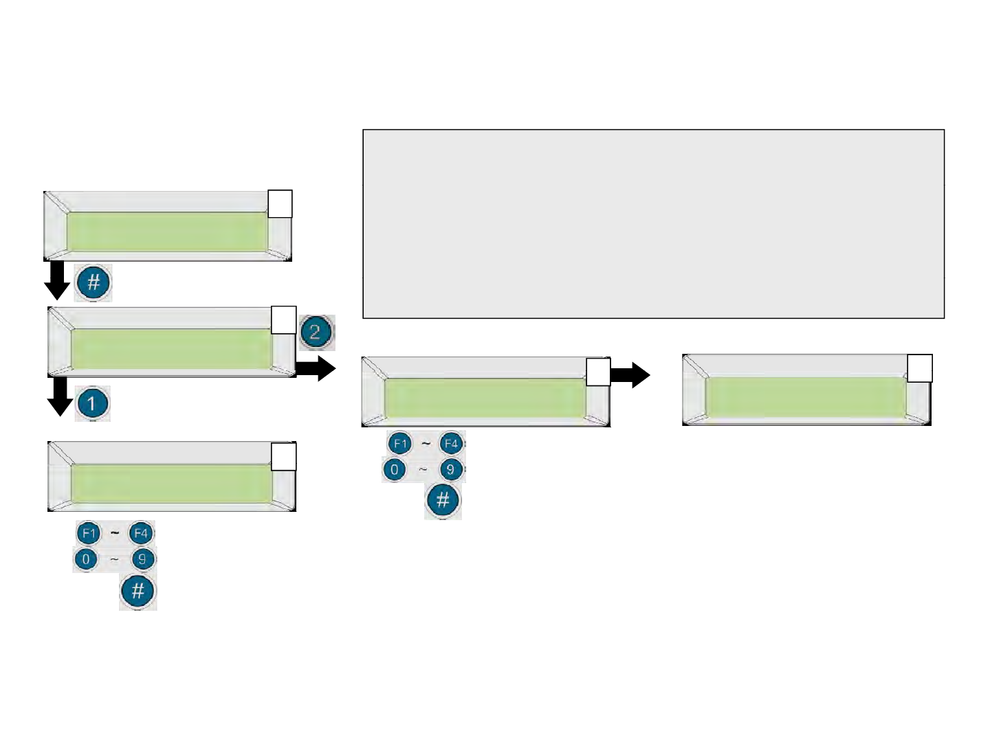
22> SET ALM FUN (external alarm function setup)
When opening a door and entering, an alarm will activate after pressing a set function key and inputting a card, fingerprint or ID
number.
number.
This will be effective to alert security guards or law enforcement when an intruder forces a user to access a door.
NOTE :
To activate an alarm to indicate an intrusion press the function key at the
22> SET ALM FUN
P th ‘#’ i t 22
To
activate
an
alarm
to
indicate
an
intrusion
,
press
the
function
key
at
the
corresponding user/admin page from the machine and input an ID, fingerprint
or card.
Screen 2 explanation
1: RELAY – activates an external alarm.
2 BUZZER
it lb f th hi i ti td
1
22> SET ALM FUN
1:RELAY 2:BUZZER
2
44
P
ress
th
e
‘#’
s
i
gn a
t
22
>
2
:
BUZZER
–
an
i
n
t
erna
l
b
uzzer
f
rom
th
e mac
hi
ne
i
s ac
ti
va
t
e
d
.
- Users may setup a function key to a RELAY or BUZZER
5
3
4
22> SET ALM FUN
[Buzz] FUN= F0-0
4
Button 1 : External alarm setup
Button 2 : Internal buzzer setup
Alarm setup complete
Press a function
key from F1
SETTING
COMPLETED
5
22> SET ALM FUN
[Relay] FUN= F1-2
Alarm
setup
complete
Press a function
key from F1
key
from
F1
through F4, then
press a button 0
through 9 and
press the “#” sign
through F4, then
press a button 0
through 9 and
press the “#” sign
28
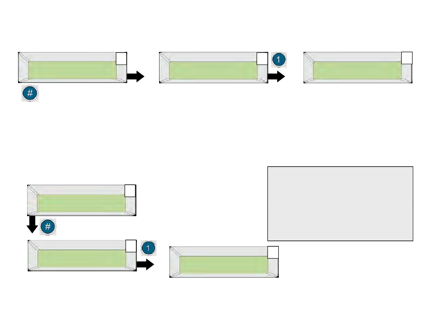
23> SET ANTIPASS (Anti-Pass Back)
When a controller is located at an entrance and exit, a user must have permission to exit.
(Ex Parking lot management office security etc)
(Ex
.
Parking
lot
management
,
office
security
etc)
23> SET ANTIPASS 23> SET ANTIPASS
1:YES 2:NO [1] SETTING
COMPLETED
1 2 3
Button 1 : Anti-pass back setup
Button 2 : Anti-pass back disable
[1] : ‘1’ for anti-pass back setup
[2] : ‘2’ for anti-pass back disable
Press the ‘#’ sign at 23> Anti-Pass setup
complete
24> SET FIRE (fire/intrusion detect setup)
This function is connected to a fire alert system. An alert signal is activated when there is a fire or intrusion.
24> FIRE-SENSOR
NOTE :
-This function is connected to a fire alert
system. An alert signal is activated when
1
2
there is a fire or intrusion and all doors are
forced open
-Intrusion detect closes all doors when an
intrusion is detected.
Press the ‘#’ sign at 24>
24> FIRE-SENSOR
1:YES 2:NO [1]
2
3
SETTING
COMPLETED
Button 1 : fire detect setup (intrusion detect
disable
)
3
29
Fire/intrusion detect setup
complete.
)
Button 2 : fire detect disable (intrusion setup)
[1] : ‘1’ for fire detect setup
[2] : ‘2’ for intrusion setup
25> SET SECRET (ID security)
For added security, ID shown in the LED screen will show as “********” when receiving authorization for entry.
25> SET SECRET
NOTE :
-Regardless of the digits of the ID
f/dithfllii
1
Press the ‘#’ sign at 25>
25>
SET SECRET
SETTING
o
f
a user
/
a
d
m
i
n,
th
e
f
o
ll
ow
i
ng
i
s
shown “********”
23
25>
SET
SECRET
1:ON 2:OFF [1]
Button 1 : ID security setup
Button 2 : ID security deactivate
SETTING
COMPLETED
ID security setup complete
26> SET LIMIT
In this menu authorization is given once every set times (units of 10 minutes).
26> SET LIMIT 26> SET LIMIT
[MIN]
<
0
-
600
>
] : 010
SETTING
COMPLETED
2 3
1
Press the ‘#’ at 26>
[MIN] 0
600 ]
:
010
Time is set in units of 1 minute.
The above shows “10” therefore is
10 minutes
COMPLETED
Entry limit setup
complete
30
10
minutes
.
If a user is authorized at AM10:00,
the user is unauthorized until
AM10:10
27> SET DAYLIGHT
This function is used to change or recover the time at a certain period in the controller.
(Ex
-
Summer Time)
(Ex
Summer
Time)
6
NOTE :
Ex.)
Chan
g
e the time to
27> SET DAYLIGHT
6
SETTING
COMPLETED
St lt
Press the
‘
#
’
sign at 27>
g
October 11th 10:00 at
September 11th 9:00.
Change the time back to
2005 September 15
th
at
1
Y M D H M
2 5
Y M D H M
S
e
t
up comp
l
e
t
e.
Press
the
#
sign
at
27>
2005
September
15
at
2005 October 15th 14:00.
Warning : The setup of
this menu can be set up in
1. 05 : 09 : 11 09 :00
Press the ‘#’ after setting up the
changed times
4. 05 :09 : 12 19 : 00
Press the ‘#’ sign after setting up
new time of recovery
the program as well. When
setting up from a controller
that is connected to a
computer, the computer’s
time will interfere.
3
Y M D H M
2. 05 : 10 : 11 10 :00
4
changed
times
Y M D H M
3. 05 : 10 :15 14 : 00
Therefore, the time should
be set offline. For
communication purposes,
setup from the program.
(For instructions on how to
Press the ‘#’ sign after setting up the
time that is changed from the daylight
savings
Press the ‘#’ sign after setting up
the time of recovery.
(For
instructions
on
how
to
set up from the program,
please refer to the program
manual)
31
28> VIEW AT-FUNC (View setup function key)
This function automatically saves the function key to the event without pressing any function keys only within a set time
zone This function is usually used to save users from pressing the function key to sign in and out of work all the time In
thi
s
zone
.
This
function
is
usually
used
to
save
users
from
pressing
the
function
key
to
sign
in
and
out
of
work
all
the
time
.
In
thi
s
menu you only have to assign a function key to a set time zone from the program. (See the program manual for edit and
setup methods)
List navigation
button
1
2
28> VIEW AT-FUNC [ 01 ] DAY : ALL
13:00 18:00 F4-9
Next Button
Back Button
EitM
Press the
‘
#
’
sign when the
The above shows: All da
y
s
1
2
E
x
it
M
enu
Press
the
#
sign
when
the
above is shown.
y
from 13:00 to 18:00 “F4-9”
function key is automatic set
so users do not have to
press the function key.
29> VIEW AT
DOOR ( i t t d ti )
29>
VIEW
AT
-
DOOR
(
v
i
ew se
t
au
t
o
d
oor
ti
me zones
)
In this menu times are recorded when an automatic door setup at the program is activated. This menu is used only to view set
times for automatic doors. (for editing and setup procedures please refer to the program manual.)
29> VIEW AT
DOOR
[01] DAY ALL
List navigation
button
forward
21
29>
VIEW
AT
-
DOOR
[
01
]
DAY
:
ALL
13:00 - 18:00 back
exit
Ex) the automatic doors are in
o
p
eration from 13:00 to 18:00
Press the ‘#’ sign at 29>
32
p
everyday
30> VIEW AT-MODE (view time management setup)
This function is used for changing activation modes at set times. This is different from the switching modes in menu 13. In this
function operation modes are changed automatically Only the operation mode
’
s set times are shown (for editing and detailed
function
,
operation
modes
are
changed
automatically
.
Only
the
operation
mode s
set
times
are
shown
.
(for
editing
and
detailed
information, please refer to the program manual)
List navigation
buttons
Forward
1 2
30> VIEW AT-MODE [ 01 ] DAY : fri
11:00 14:00 [FP]
Forward
Back
Exit
Ex) from Friday 11:00 to 14:00
o
p
eration mode is “FINGER”
Press ‘#’ at 30>
p
31> VIEW BELL
31>
VIEW
BELL
In this function, a bell is rung at set times automatically. This is usually used for school classroom bells or alarms.
Users are only able to view set bell time zones. (for editing and detailed information please refer to the program
manual.)
31> VIEW BELL
[01]DAY:fri
List navigation
buttons
forward
2
1
Press ‘#’ at 31>
31>
VIEW
BELL
[
01
]
DAY
:
fri
11:00 T=005
Ex) at Friday 11:00 a bell is rung
for 5 seconds
back
exit
33
for
5
seconds
.
32> VIEW T-ZONE
The user is able to see saved Timezone Index. This menu is only able to view timezones that are setup.
(for editing and detailed explanation please refer to the program manual.)
32> VIEW T
ZONE
32> VIEW T
ZONE
List navigation
button
Forward
1 2
32>
VIEW
T
-
ZONE
Press the ‘#’ sign at 32>
32>
VIEW
T
-
ZONE
INDEX: 001 [Y] Back
Exit
View the setup timezone.
(Up to 254 functions)
(Up
to
254
functions)
33> VIEW NO
FUN (View function keys with no
33>
VIEW
NO
-
FUN
(View
function
keys
with
no
functions)
This menu shows events saved when verification is denied and a door does not open. Users may only view function
keys set up in the menu (for editing and detailed information please refer to the program manual
keys
set
up
in
the
menu
.
(for
editing
and
detailed
information
please
refer
to
the
program
manual
.
33> VIEW NO-FUN
[F1
-
1] [F2
-
1]
21
Press ‘#’ at 33>
[F1
1]
[F2
1]
[F3-1] [F4-1]
Function key is setup as “F1-1” “F2-
1” “F3-1” “F4-1”
34
34> S/W VERSION VIEW
View the current controllers Firm Ware Version
NOTE:
34> S/W VERSION
VER : 3.00
NOTE:
-The current F/W version is
3.00 and future F/W will be
updated.
34> S/W VERSION
12
Press the ‘#’ sign at 34>.
35> TCP/IP DHCP
Exiting the menu.
35> TCP/IP DHCP 35>TCP/IP DHCP
1. ON 2.OFF [2]
1 2
Press the ‘#’ sign. TCP/IP DHCP On/Off
verification
35
36> IP ADDRESS (VIEW IP ADDRESS)
View the current controller’s IP ADDRESS
NOTE:
36> IP ADDRESS
192.168..001.224
NOTE:
-The current IP ADDRESS is
display. You can change this Ip
address as you want.
36> IP ADDRESS
12
Press the ‘#’ sign at 36>.
37> SUBNET MASK
View the current controller’s SUBNET MASK.
37> SUBNET MASK 37>SUBNET MASK
255.255.255.0
1 2 NOTE:
-The current Subnet Mask
address is set to
255.255.255.0. This menu is
lf i i th dd
Press the ‘#’ sign.
on
l
y
f
or v
i
ew
i
ng
th
e a
dd
ress.
Address setting is done from
the terminal or the S/W.
36
36> GATEWAY
View the current controller’s IP ADDRESS
NOTE:
38> GATEWAY
192.168..001.001
NOTE:
-The current GATEWAY is set
to 192.168.001.001. This menu
is only for viewing the address.
Address setting is done from
38> GATEWAY
12
Address
setting
is
done
from
the terminal or the S/W.
Press the ‘#’ sign at 38>.
39> LANGUAGE
View the current controller’s LANGUAGE OPTION.
39> LANGUAGE 39>LANGUAGE
1. KR 2. EN 3. CH
1 2 NOTE:
-1. KR (KOREAN)
-2. EN (ENGLISH)
3 CH (CHINESE)
Press the ‘#’ sign.
-
3
.
CH
(CHINESE)
37
40> SAVE ENROLL
Saving currently registered users to the USB Memory
NOTE:
40> SAVE ENROLL
1. YES 2. NO
NOTE:
-This menu displays how to
save registered users to the
USB memory stick.
O l USB2 0(FAT FAT32
40> SAVE ENROLL
12
-
O
n
l
y
USB2
.
0(FAT
,
FAT32
format) can be used.
Press the ‘#’ sign at 40>.
41> LOAD ENROLL
Uploading registered users to the controller from the USB Memory.
41> LOAD ENROLL 41>LOAD ENROLL
1.YES 2. NO
1 2
Press the ‘#’ sign.
38
42> SAVE SLOG
Saving ALL EVENTS from the controller to the USB Memory.
36> SAVE SLOG
1. YES 2. NO
42> SAVE SLOG
12
Press the ‘#’ sign at 42>.
43> SAVE GLOG
Saving Time & Attendance EVENTS from the controller to the USB Memory.
43> SAVE GLOG 43>SAVE GLOG
1. YES 2. NO
1 2
Press the ‘#’ sign.
39
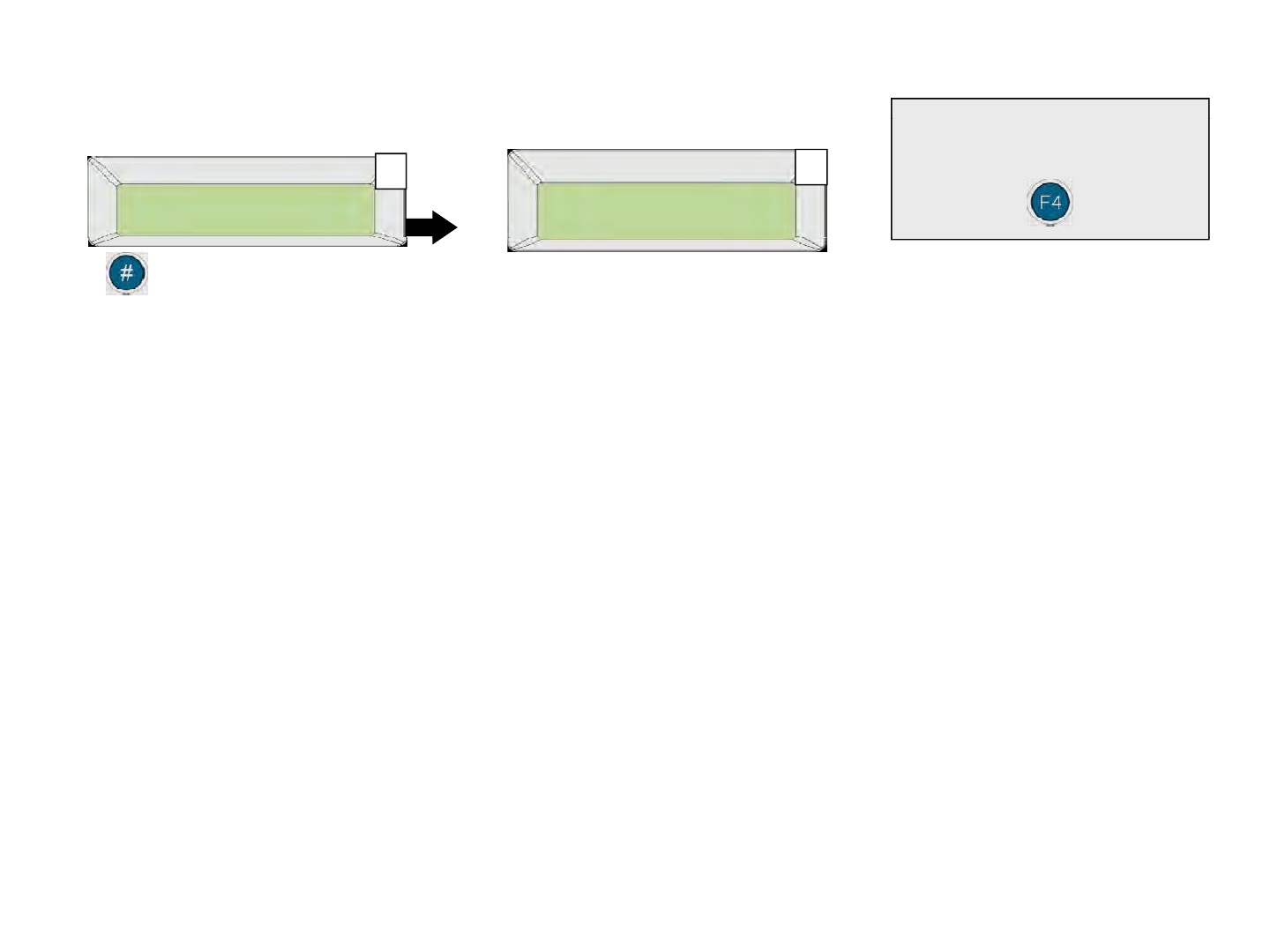
44> EXIT (EXITING THE MENU)
Closing the menu
NOTE:
[CD]
12:56:32 [THU]
NOTE:
-Press ‘F4’ to exit menu at
anytime.
44> EXIT
12
Press the ‘#’ sign at 44>. To initial screen
40

CHAPTER 3
CHAPTER
3
- OTHERS -
41
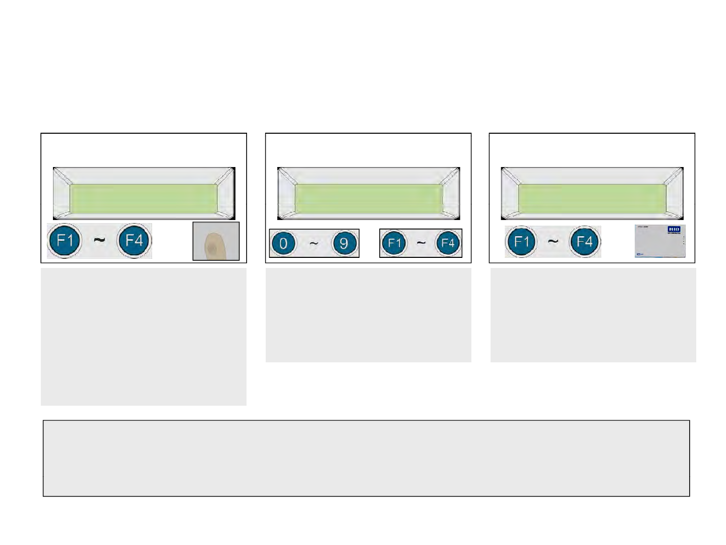
How to use the function key
The Function Key is usually used in for time & attendance.
The admin is able to setup a certain value to a function key in the program (F1 = sign in) The admin is then able to find
out the sign in status.
[ A N Y M O D E ]
16 10 46 [THU]
ACTIVATING FUNCTION KEY
THROUGH FINGERPRINT
INPUT
[ A N Y M O D E ]
16 10 46 [THU]
[ A N Y M O D E ]
16 10 46 [THU]
ACTIVATING FUNCTION KEY
THROUGH ID INPUT ACTIVATING FUNCTION KEY
THROUGH CARD INPUT
16
:
10
:
46
[THU]
16
:
10
:
46
[THU]
16
:
10
:
46
[THU]
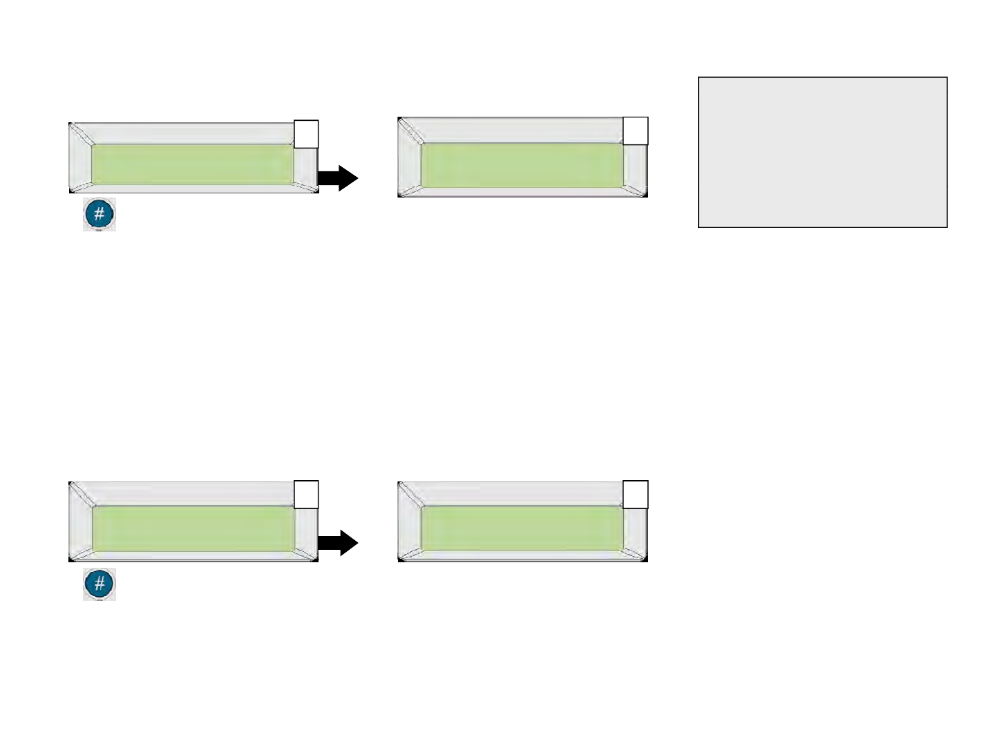
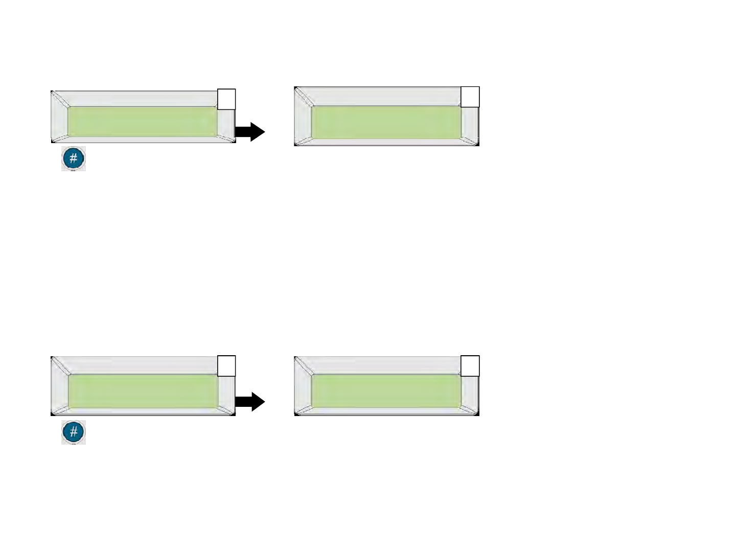
++ +
1. Press a function key (F1~F4) at
the initial screen or press a function
key after pressing a number key.
2.
Enter the ID number used for
1. PRESS A NUMBER KEY AFTER
PRESSING A FUNCTION KEY.
Press a function key (F1~F4)
only or, press a number key after
pressing a function key.
1. Press a function key (F1~F4) at
the initial screen or press a function
key after pressing a number key.
2. Enter the ID number used for
2.
Enter
the
ID
number
used
for
entry.
pressing
a
function
key.
2. INPUT A FINGERPRINT USED
FOR ENTRY.
2.
Enter
the
ID
number
used
for
entry.
NOTE :
The function key should be used with the time & attendance program. Only enter a function for the time & attendance
and onl
y
saves data of entries.
42
y