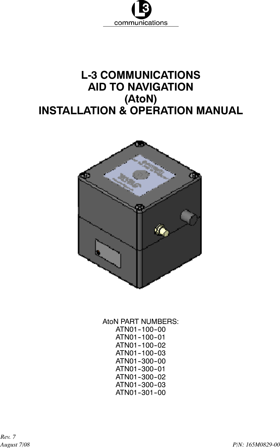
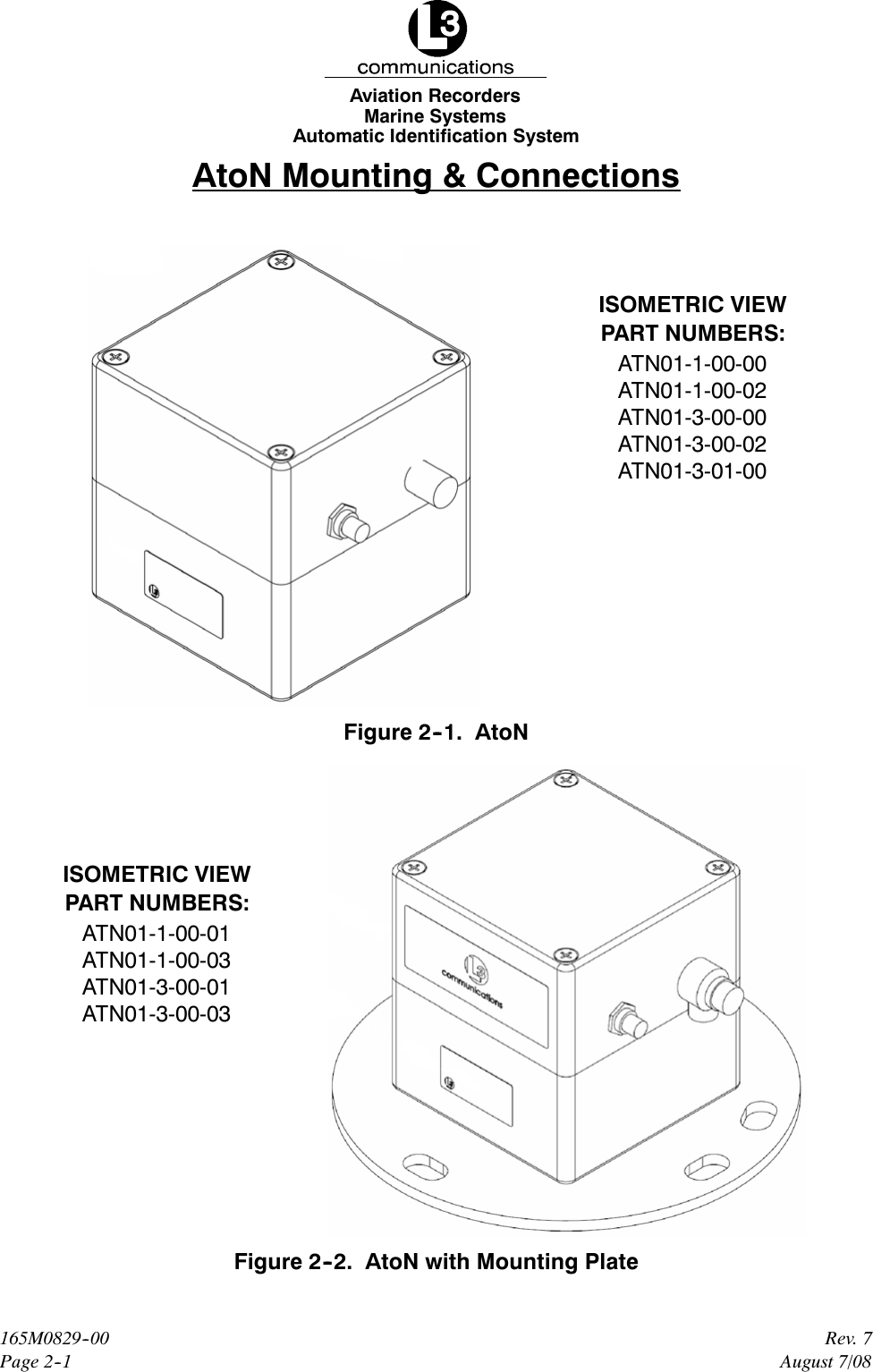
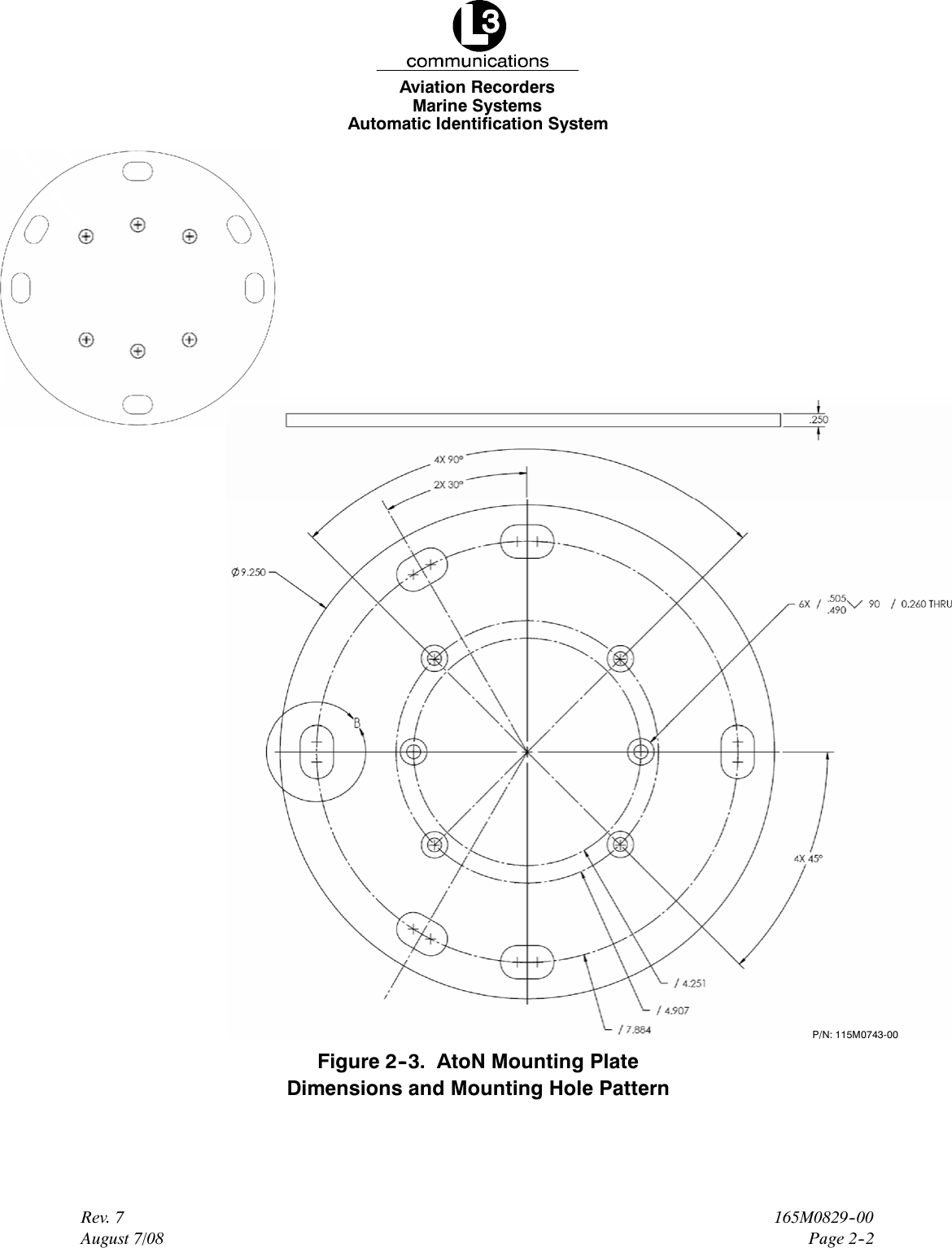
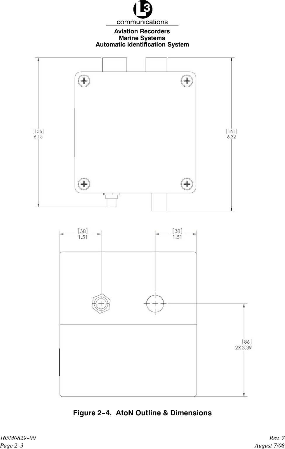
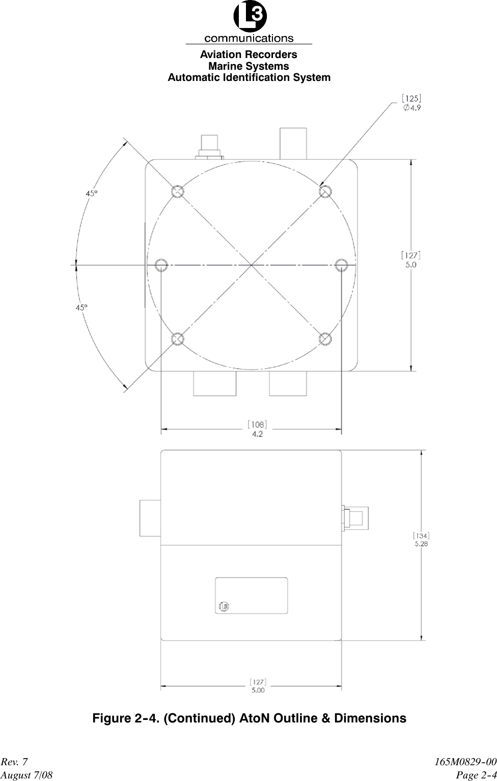
L3 Technologies 0ATN01 Aid to Navigation (AtoN) AIS User Manual title

L-3 Communications Aid to Navigation (AtoN) AIS title

Contents

user install

P/N: 165M0829-00August 7/08Rev. 7L-3 COMMUNICATIONSAID TO NAVIGATION(AtoN)INSTALLATION & OPERATION MANUALAtoN PART NUMBERS:ATN01--100--00ATN01--100--01ATN01--100--02ATN01--100--03ATN01--300--00ATN01--300--01ATN01--300--02ATN01--300--03ATN01--301--00
Marine SystemsAviation RecordersAtoN Installation & Operation ManualRev. 7August 7/08165M0829-00Page iiL--3AtoN I&O Manual 165M0829-00Rev. 7August 7/08EXPORT CONTROL STATEMENT AIS TECHNOLO-GY / DATA:“This technical data is controlled under the Export Ad-ministration Regulations ECCN 5E992, and may not beexported to a Foreign Person, either in the U.S. orabroad, without the proper authorization of the U.S. De-partment of Commerce.”This manual contains date sensitive information.To verify the latest revision level of this manual,visit our document download site athttp://www.L-3ar.net.ECopyright 2008 by L-3 Communications.All rights reserved. No part of this manual may be re-produced or utilized in any form or by any means, elec-tronic or mechanical, including photocopying, record-ing, or by information storage and retrieval system,without permission in writing.Inquiries should be addressed to:L-3 CommunicationsAviation Recorders PublicationsVendor Code: 06141P. O. Box 3041Sarasota, Florida 34230
Marine SystemsAviation RecordersAtoN Installation & Operation ManualRev. 7August 7/08165M0829-00Page iiiGENERALThis product and related documentation must be reviewed for familiarization with safetymarkings and instructions before operation.This board was constructed in an ESD (electro–static discharge) protected environment. This isbecause most of the semiconductor devices used in this board are susceptible to damage by staticdischarge.Depending on the magnitude of the charge, device substrates can be punctured or destroyed bycontact or mere proximity of a static charge. The results can cause degradation of device perfor-mance, early failure, or immediate destruction.These charges are generated in numerous ways such as simple contact, separation of materials,and normal motions of persons working with static sensitive devices.When handling or servicing equipment containing static sensitive devices, adequate precautionsmust be taken to prevent device damage or destruction.Only those who are thoroughly familiar with industry accepted techniques for handling static sen-sitive devices should attempt to service circuitry with these devices.In all instances, measures must be taken to prevent static charge build–up on work surfaces andpersons handling the devices.
Marine SystemsAviation RecordersAtoN Installation & Operation ManualRev. 7August 7/08165M0829-00Page ivTHIS PAGE IS INTENTIONALLY LEFT BLANK.
Marine SystemsAviation RecordersRev. 7August 7/08165M0829--00Page 1--1AtoN Introduction1.1. GeneralThe Aids to Navigation (AtoN) is an Automatic Identification System (AIS) transmitterthat is fully compliant to the technical specifications defined by the IMO and outlinedin ITU.R.M 1371-1. The transmitter is designed to be installed in weather and navi-gation buoys with no periodic maintenance required. The transmitter employs thelatest radio frequency and FATDMA technology to provide a high performance, auto-mated, and reliable identification system. The transmitter is a fully automated sys-tem, which ties into the buoy’s navigational and/or weather monitoring instrumenta-tion to provide automatic transmission of navigational and meteorological data (de-pendent on the installation).The Transponder is a fully automated system. This means that once it is installedand turned on, no maintenance is required to keep it operational.The L--3 ProTec Inland Waterways/Class A Automatic Identification Systemtransponder is manufactured in Sarasota, Florida, United States of America, pursu-ant to ISO 9000.1.1.1. System OverviewThe AtoN is an Aids to Navigation System fully compliant with the IMO specificationsdefined in IMO MSC.74(69) Annex 3, IEC 62320--2-2, and ITU.R M.1371-3.Withtheaddition of the FATDMA controllers, the AtoN provides a cost-effective AIS solution,which will meet the needs of any waterway required to transmit AtoN data. The com-pact, single-box design allows the AtoN to be easily incorporated into any buoy lay-out thus simplifying installation and cabling requirements.The AtoN has been designed as maintenance-free unit, which makes extensive useof surface mount technology (SMT). The repair of printed wiring assemblies (PWAs)containing SMT components requires specialized factory equipment, training, andtechniques, therefore, such PWAs are not field-repairable.As a result, maintenance philosophy for the AtoN is replacement of failed assemb-lies. In the case of the AtoN, the entire unit should be sent back to the factory, in theunlikely case of a failure.Attempts by anyone but an authorized L--3 representative to repair the AtoN will voidthe warranty.
Marine SystemsAviation RecordersRev. 7August 7/08165M0829--00Page 1--2For repair service, call or email to obtain an RMA # or Form:L-3 Communications, Aviation Recorders6000 E. Fruitville RoadSarasota, FL 34232 USAAttn: Repair DepartmentTel: (941) 377-5558Fax #: (941) 377-55851.1.2. ReferencesIMO Resolution MSC.74(69), Annex 3, Recommendation on Performance Standardsfor a Universal Shipborne Automatic Identification Systems (AIS)International Telecommunications Union Sector for Radio Communications (ITU-R)Recommendation M.1371-3, Technical Characteristics for a Universal ShipborneAutomatic Identification System Using Time Division Multiple Access in the MaritimeMobile Band.IEC 61993-2 Edition1, Maritime Navigation and Radio communication Requirements- Automatic Identification Systems (AIS) - Part 2: Class A shipborne Equipment ofthe Universal Automatic Identification System (AIS) - Operational and PerformanceRequirements, Methods of Test and Required Test ResultsIEC 60945 Edition 4, Maritime Navigation and Radio communication Equipment andSystems - General Requirements - Methods of Testing and Required Test Results.IALA Recommendation on AIS Shore Stations and Networking Aspects Relating tothe AIS Service, Edition 1.0, September 5, 2002IEC 61162-1 Edition 1.0, Maritime Navigation and Radio communication Equipmentand Systems - Digital Interfaces - Part 100: Single Talker and Multiple ListenersIEC 61162-2 Edition 1.0, Maritime Navigation and Radio communication Equipmentand Systems - Digital Interfaces - Part 100: Single Talker and Multiple Listeners,High-Speed Transmissions1.1.3. AcronymsABM Addressed Binary MessageABK Acknowledgment MessageACA AIS Channel AssignmentACK Acknowledgment MessageARM Advanced RISC MachineARPA Automatic Radar Plotting AidBBM Broadcast Binary MessageCOG Course Over GroundDGPS Differential Global Positioning SystemDSP Digital Signal Processor
Marine SystemsAviation RecordersRev. 7August 7/08165M0829--00Page 1--3FATDMA Fixed Access Time Division Multiiple AccessGGA Global Positioning Fix DataGLL Geographic Position, Latitude/LongitudeGNSS Global Navigation Satellite SystemGPS Global Positioning SystemGSA GPS DOP and Active SatellitesGSV GPS Satellites in ViewHDG Heading, Deviation & VariationHDT Heading, TrueIEC International Electrotechnical CommissionIMO International Maritime OrganizationLRF Long Range FunctionLFI Long Range InterrogationMMSI Maritime Mobile Service IDNMEA National Marine Electronics AssociationNV Non--VolatilePLL Phase Locked LoopRAIM Receiver Autonomous Integrity MonitoringRATDMA Random Access Time Division Multiiple AccessRF Radio FrequencyRMC Recommended Minimum Data for GPSROT Rate of TurnSOG Speed Over GroundSOTDMA Self Organized Time Division Multiple AccessSSD Station Static DataTDS Target Display SoftwareTXT Status/Indication MessageVBW Dual Ground/Water SpeedVDL VHF Data-link Other Vessel MessageVDM VHF Data-link MessageVDO VHF Data-link Own-vessel MessageVSD Voyage Static DataVSWR Voltage Standing Wave RatioVTG Track Made Good and Ground SpeedZDA Date and Time
Marine SystemsAviation RecordersRev. 7August 7/08165M0829--00Page 1--41.2. Technical SpecificationsStandards IMO MSC.74(69) Annex 3, IEC 61993-2 Ed. 1, ITU.R.M.1371-1, IALAA-126TDMA TransmitterTX Frequency: 156.025 MHz - 162.025 MHzTransmitter Power: 12.5 W max.Channel Bandwidth: 25 kHzOutputMessage 6, Message 21 as defined in ITU.R.M.1371-1Power Supply12 VDC nominalPower ConsumptionMessage 21 (FA) every 3 minutes for 30 minutes (10 full cycles):FAverage Instantaneous Current: 14.2 mA (Vin = 12.0 Vdc)FAverage Instantaneous Power: 170 mWMessage 21 (RA) every 3 minutes for 30 minutes (10 full cycles):FAverage Instantaneous Current: 125 mA (Vin = 12.0 Vdc)FAverage Instantaneous Power: 1500 mWPower usage in continuous receive mode:FAverage Instantaneous Current: 323 mA (Vin = 12.0 Vdc)FAverage Instantaneous Power: 3880 mWEnvironmentIEC 60945 Ed. 4 for Unprotected EnvironmentFrequencyVHF Marine Band
Marine SystemsAviation RecordersRev. 7August 7/08165M0829--00Page 1--51.3. AtoN Description1.3.1. Compact DesignThe completely self-contained L-3 AtoN has outside dimensions of 5.24” W (133mm.) x 4.73” H (120 mm.) x 4.73” D (120 mm.). It is easily mounted inside the buoyusing a flush-mount bracket.MODEL ATONAIS FOR AIDS TO NAVIGATION SYSTEMSPART NUMBER MATRIXATN01–XXX–XXCONFIGURATIONTYPE 1 (TRANSMIT ONLY) 1.........TYPE 2 (LIMITED RECEIVER) 2......TYPE 3 (FULL ATON) 3..............FEATURES00 BASIC......01 MOUNTING FLANGE......02 RF LIGHTNING PROTECTION......03 MOUNTING FLANGE & RF......LIGHTNING PROTECTIONINTERNAL DESIGNATORFigure 1--1. AtoN Part Number Matrix
Marine SystemsAviation RecordersRev. 7August 7/08165M0829--00Page 1--6THIS PAGE IS INTENTIONALLY LEFT BLANK.
Marine SystemsAviation RecordersAutomatic Identification SystemPage 2--1Rev. 7165M0829--00August 7/08AtoN Mounting & ConnectionsISOMETRIC VIEWPART NUMBERS:ATN01-1-00-00ATN01-1-00-02ATN01-3-00-00ATN01-3-00-02ATN01-3-01-00Figure 2--1. AtoNISOMETRIC VIEWPART NUMBERS:ATN01-1-00-01ATN01-1-00-03ATN01-3-00-01ATN01-3-00-03Figure 2--2. AtoN with Mounting Plate
Marine SystemsAviation RecordersAutomatic Identification SystemPage 2--2165M0829--00Rev. 7August 7/08P/N: 115M0743-00Figure 2--3. AtoN Mounting PlateDimensions and Mounting Hole Pattern
Marine SystemsAviation RecordersAutomatic Identification SystemPage 2--3Rev. 7165M0829--00August 7/08Figure 2--4. AtoN Outline & Dimensions
Marine SystemsAviation RecordersAutomatic Identification SystemPage 2--4165M0829--00Rev. 7August 7/08Figure 2--4. (Continued) AtoN Outline & Dimensions
Marine SystemsAviation RecordersAutomatic Identification SystemPage 2--5Rev. 7165M0829--00August 7/08Figure 2--5. AtoN Connections
Marine SystemsAviation RecordersAutomatic Identification SystemPage 2--6165M0829--00Rev. 7August 7/08The power cable, Part Number 024M0926--00, is supplied by L--3.Figure 2--6. Power Connection Pin OutFigure 2--7. GPS Connection Pin OutGND*PINPVUCONNECTRSVDRSVDRLKGGNDRSVDRSVDRSVDTSABI E C --- T X *I E C --- R X *SYNC+S Y N C ---Figure 2--8. Sensor Data Connection Pin Out**The Sensor Data cable, Part Number 024M0841--00, is supplied by L--3.*Used to connect to the AtoN IEC/serial port to a DB9 connector
Marine SystemsAviation RecordersAutomatic Identification SystemPage 2--7Rev. 7165M0829--00August 7/08**Signals names are with respect to the AtoN (RS--232).Installing the VHF AntennaInstallation of a VHF antenna is as important to reliable communications as thetransceiver itself. It is recommended that a high quality antenna be purchased froman established source and that all manufacturer’s instructions be followed withparticular attention to cable routing and connector installation. Some importantconsiderations in antenna installation are:FIn general, VHF antennas should be located as high as practical on thebuoy and separated as much as possible from each other.FThe VHF antenna should be placed in an elevated position with a mini-mum of 2 meters clearance from any construction that is made with con-ductive material. In addition, it should not be installed close to any largevertical obstruction, and the VHF antenna should have a 360°line of sightto the horizon.To install the VHF antenna, perform the following:(Refer to Figure 2--9.)(1) Position the antenna mounting bracket on a rigid and structurally sound sur-face.(2) Install the antenna on the antenna mount.NOTE: Use only high quality RG213/RG214 coaxial cable and keepcable length as short as possible to reduce signal attenua-tion.(3) Run the coaxial cable from the antenna to the transponder location.(4) Trim cable to length leaving a few inches slack at the transponder.(5) Attach the connectors to the end of the coaxial cable.(6) Connect the cables to the transponder. Soldering the connection isrecommended.
Marine SystemsAviation RecordersAutomatic Identification SystemPage 2--8165M0829--00Rev. 7August 7/08Installing the GPS AntennaThe correct installation of a GPS antenna is crucial to the operation of the trans-ponder because the internal transmission synchronization relies on the accuracy ofthe time signal obtained from the GPS. It is recommended that a high quality GPSantenna be purchased from an established source and that all manufacturer’sinstructions be followed with particular attention to cable routing and connectorinstallation. Some important considerations in GPS antenna installation are:FGPS antennas should be located to provide a clear, unobstructed view ofthe sky.FGPS signals can also be affected negatively by VHF transmissions, andthe GPS antenna should be positioned at least 3 meters from the VHFantenna, if possible.FThe GPS antennas can be flat mounted onto any surface but it is recom-mended that it be elevated as high as possible to prevent ice or sprayfrom negatively impacting the signal reception.To install the GPS antenna, perform the following:(Refer to Figure 2--9)(1) Position the antenna mounting bracket and/or antenna mast on a rigid andstructurally sound surface.(2) Install the antenna on the antenna mount.NOTE: Use only high quality RG213/RG214 coaxial cable and keep cablelength as short as possible to reduce signal attenuation.(3) Run the coaxial cable from the antenna to the transponder location through anexisting throughhull.(4) Trim cable to length leaving a few inches slack at the transponder.(5) Attach the connectors to the end of the coaxial cable.(6) Connect the cable to the transponder. Soldering the connection isrecommended.
Marine SystemsAviation RecordersAutomatic Identification SystemPage 2--9Rev. 7165M0829--00August 7/08Figure 2--9. AtoN Transponder Antenna Diagram
Marine SystemsAviation RecordersAutomatic Identification SystemPage 2--10165M0829--00Rev. 7August 7/08THIS PAGE IS INTENTIONALLY LEFT BLANK.
Marine SystemsAviation RecordersRev. 7August 7/08165M0829--00Page 3--1AtoN Configuration3.1. IntroductionThe AtoN may transmit messages 6 and/or 21 as specified by ITU--R M. 1371--1.Message 6 is defined as an Addressed Binary Message (ABM). It can be variablein length depending on the amount of binary data and can consist of 1 to 5 slots.Data from a message 6 may contain a status report on the health of the buoy, orother information. As implied in the name, the message must be addressed. Thatis, it must contain the appropriate destination MMSI of the base station that is to re-ceive the transmission.Message 21 is defined as an Aids-to-Navigation Report. This message is usuallytransmitted every 3 minutes and contains the origination MMSI, name of the AtoN (ifapplicable), type of AtoN (fixed or floating), position of the AtoN and the positionalaccuracy. The position information is derived from the on--board GPS receiver thatis internal to the AtoN. As well as the deriving position, the GPS receiver is used asthe basis for all transmission timing on the VDL. Unlike the message 6, this report ismeant to be seen by all AIS transponders.3.2. ConfigurationThe transmit functions of the AtoN must be configured prior to installation. The con-figuration parameters specify what messages are transmitted over the air, how oftenthe transmissions occur and what slot on the VHF data link (VDL) they are trans-mitted on.NOTE: All message assignments and intervals must be defined and ap-proved by the appropriate competent authority where the AtoNis to be installed.Configuration is accomplished via a personal computer (PC) using a simple terminalemulator. An AtoN configuration cable is connected from the PC’s serial port to theserial interface connector of the AtoN. In this example, WindowstHyperTerminal isused. Connect the PC to the AtoN using the configuration cable.3.3. Firmware UpdateIn order to update AtoN firmware, the following is required:FPower Cable: For details on the pin out, refer to Figure 2--6.FCommunications Cable: For details on the pin out, refer to Figure 2--8.
Marine SystemsAviation RecordersRev. 7August 7/08165M0829--00Page 3--2FFirmware Update Package3.4. OverviewThe AtoN contains two processors, an ARM and a DSP. The ARM has completecontrol over the DSP power and reset lines. The DSP runs the RF subsystem, butonly when the ARM has enabled it to do so.When the AtoN is up and running, the ARM Debug Unit (DBGU) serial port is usedfor Trace message output and shows ARM operational status and information. Thisinterface also functions as a menu-based configuration and command and controlchannel for the unit, with a set of built-in “hot key” sequences for initiating variousoperations. The interface to this channel is typically a serial console program suchas HyperTerminal. The ARM DBGU channel runs at 115200 Baud, 8 Data Bits, andNo Parity.NOTE: The AtoN’s sleep state may interfere with the configuration pro-cess.When left unattended, the AtoN unit may go into a “sleep” state (enter StandbyMode). As of Rev 1.14H of the ARM software, this is the case for both Type 1 andType 3 units. Standby Mode can interfere with running tests, loading code and con-figuring the AtoN unit. The AtoN can be prevented from entering Standby Mode byleaving the GPS antenna disconnected. The AtoN will not enter standby mode if ithas no time input that the GPS would normally provide.As of Rev 1.14H of the ARM software, the “Standby Enable” can be toggled on andoff using the ^P^P sequence (Ctrl Key with P, twice) at the ARM console interface.In order to run tests on the RF subsystem it is necessary that the DSP be poweredup and released from Reset. This is completely under control of the ARM processor,making it impossible to run tests on the DSP unless the ARM is cooperating. Use the“T-2-E” sequence at the ARM console to ensure that the DSP is running.The ARM DBGU serial interface also provides some user control in the form of Menuand command entry. There are three menus currently implemented, a System Con-figuration Menu, a General Configuration Menu and a Test Menu.The System Configuration Menu is invoked by typing ‘S’, the General ConfigurationMenu is invoked by typing ‘C’, and the Test Menu is invoked by typing ‘T’.On entry to any of these Menus, normal AtoN operation is terminated. Since the op-erations available in the Setup, Test and Config menus can leave the AtoN in anindeterminate state, a Reboot always follows the exit from these menus. This is au-tomatic upon termination of Menu activity. The operations associated with these Me-nus are discussed further in subsequent sections of this document.
Marine SystemsAviation RecordersRev. 7August 7/08165M0829--00Page 3--3Failure ModesFor Transmission Fault/Disabled Antenna:A disabled antenna is detected by the AtoN DSP as an antenna with a high VSWRduring the transmission of a message. If a high VSWR is detected, the DSP stopstransmission before a message completes transmission.For Reception Fault:The AtoN uses a frequency synthesizer incorporating a digital PLL. If both receiversare locked, a Lock Detect status signal is sent indicating the receivers are function-ing. If either or both receivers fail to lock then the Lock Detect status indicates a faultand RATDMA transmissions are stopped.3.5. Resetting the AtoN from the ARM HyperTerm ConsoleWhen the AtoN is operational and Trace messages are being displayed on the ARMHyperTerm console, the unit can be Reset at any time by holding the Ctrl key andtyping a pair of ‘C’ characters in succession. This avoids the need to cycle power inorder to restart the AtoN.3.6. ARM Code UpdateIf the Baseband Board has not been updated, it may still be loaded with Micromoni-tor in Flash. In this case, the ARM code must be updated as a first step. In order todo this, please follow the procedure below.NOTE:Note that this method of updating the ARM code will workwhether Micromonitor is in Flash or not. However, it is theonly method that will work for loading an ARM standalonebinary image if Micromonitor is still resident.(7) The ARM DBGU port should be connected to HyperTerm at 115200 Baud.(8) The BMS jumper must be installed on the Baseband Board, and power applied.The BMS jumper is installed on the Baseband Board at PL10, between pins 13 and14.(9) If the BMS jumper connection is made, and power is applied to the AtoN, the Hy-perTerm console should display ‘C’ characters at approximately one per second.Once the ‘C’ characters are being displayed at the HyperTerm console, the ARMcode update can begin.(10) On the HyperTerm menu pull--down bar, select Transfer-->Send File.
Marine SystemsAviation RecordersRev. 7August 7/08165M0829--00Page 3--4(11) In the Protocol box of the subsequent pop--up window, select Xmodem.(12) Use the “Browse” button to locate the ARM binary images. Typically, these are con-tained in a folder called “Aton Images”. Select the “SerBoot.bin” file by double---clicking on it in the file list (or single--click and hit the “Open” button).(13) Hit the “Send” button in the “Send File” window. This will start the transfer.(14) On completion of the transfer the ‘C’ characters will start again. At this time, locatethe ARM executable binary image in the same folder as the “SerBoot.bin” file. Anexample would be AtoN_1_03.bin. This name corresponds to Rev 1.03 of the ARMcode. Typically, one would select the file with the highest version number, but theremay be situations where an older version is to be loaded. Note that the Micromoni-tor image could also be sent at this point instead of the AtoN binary image. TheMicromonitor image is contained in a file named “CSB_637.bin” and represents theoriginal Micromonitor image as contained on the Cogent CSB637 developmentboards that preceded the Baseband board.(15) Select the binary file to be loaded by double-clicking on it in the file list (or single--click and hit the “Open” button).(16) Next hit the “Send” button in the “Send File” window. This will start the transfer ofthe binary image.(17) On completion of the transfer the ‘C’ characters will start again. Remove the BMSjumper and power the board up again. The unit should boot normally and Tracemessages will appear in the HyperTerm window. Note that if an ARM standaloneimage was loaded, the HyperTerm connection must be at 115200 Baud (the sameas the download). However, if the Micromonitor image was restored for some rea-son (not typical) the HyperTerm connection must be set to 38400 Baud.3.7. Clearing the NV ContentSome situations may require the entire NV configuration be cleared. This is a recom-mended procedure when an ARM software update is performed because the storedNV configuration structures may not be compatible with the code that has beenloaded.Clearing the NV content does not cause the Unit Type or Serial Number to be lost.This operation restores the NV to a fresh state. This is done from the ARM Hyper-Term console while Trace messages are being displayed.Hold the Ctrl key, and type the sequence, “NVERAS”. A message should appearindicating that the NV was erased. This will erase any transmit schedule that hadbeen created, and will set all NV values to the appropriate defaults for the configuredUnit Type on the next startup.
Marine SystemsAviation RecordersRev. 7August 7/08165M0829--00Page 3--53.8. Setting Transmit Schedule Using Scheduling UtilityIt is not necessary to use the Startup Dialog to create a transmit schedule. A sched-uling utility is now part of the General Configuration Menu. This can be invoked atany time by pressing the ‘C’ key, then selecting item 3.Figure 3--10. Transmit Schedule Setup UtilityFigure 3--10 shows the control choices for building transmit schedules. The line atthe bottom of the screen shows the attributes for a new schedule entry that will becreated if the User hits the ENTER key.Hitting the “V” key displays the current view of the schedule.Hitting the “C” key clears all reservations.Hitting the ‘F’ key toggles whether the new schedule item will be FATDMA or RATD-MA.Hitting the ‘A’ key toggles whether the entry will Add or Replace to any entries for theselected Message ID and Index.Hitting the ‘T’ key toggles the Tx Mode between Normal and Back to Back transmis-sions. This option is typically set to “Normal”, but special test scenarios might require“Back to Back” transmissions.
Marine SystemsAviation RecordersRev. 7August 7/08165M0829--00Page 3--6Hitting the SHFT and ‘+’ (plus) key increases the value of the “base” or “anchor” slotupwards by 10 for the scheduled transmission.Hitting the ‘--’ (minus) key decreases the value of the “base” or “anchor” slot down-wards by 10 for the scheduled transmission.Hitting the ‘*’ key will toggle the slot adjustment to a value between 10 and 1. Thisallows for fine control over the base slot.Hitting the ‘M’ key will cycle through the Message ID and Index as choices for thenext field.Hitting the ‘I’ key increases the transmit interval value for the scheduled transmis-sion.Hitting the ‘D’ key decreases the transmit interval value for the scheduled transmis-sion.Hitting the Space Bar will cycle through the choices for the final field and change theChannel Selection.Hitting the ESC button returns the screen to the main “System Configuration Menu.”Hitting the ENTER button displays a message to “Hit Any Key to Continue...” HitENTER again, and the Transmit Schedule Setup Utility screen appears.
Marine SystemsAviation RecordersRev. 7August 7/08165M0829--00Page 4--1System Configuration Menu4.1. System Configuration MenuThe features of the AtoN “System Configuration Menu” are described in this section.A more detailed explanation of each feature, how it is configured, and its parameterswill be provided in a future version of this manual.To access the “System Configuration Menu” for the ARM, press “C” in the ARMHyperTerminal while it is transmitting data normally. The window appears, as shownbelow.If a different window is open, press “ESC,” so a “Hit Any Key to Reboot” messageappears. Press any key, so the system reboots. Press “C” to open the System Con-figuration Menu.To configure a specific feature, type in the number or letter associated with it in themenu. This opens self--explanatory options at the bottom of the screen.Figure 4--11. System Configuration MenuWhen “1” is entered in the “System Configuration Menu,” the “Current ConfigurationInformation” screen appears with a summary of the AtoN’s existing setup. The “Cur-rent Configuration Information” screen is shown below.
Marine SystemsAviation RecordersRev. 7August 7/08165M0829--00Page 4--2Figure 4--12. Current Configuration Information ScreenTo set the MMSI, enter “2” in the main “System Configuration Menu,” and the optionshown below appears at the bottom of the screen.Figure 4--13. MMSI Mode
Marine SystemsAviation RecordersRev. 7August 7/08165M0829--00Page 4--3To set the Latitude and Longitude, enter “3” in the main “System ConfigurationMenu” and the option appears at the bottom of the screen, as shown below.Figure 4--14. Configure Latitude and LongitudeTo view the current transmit schedule, enter “4” in the main “System ConfigurationMenu,” and the screen shown below summarizes the information at the bottom.Figure 4--15. Configure Transmit Schedule
Marine SystemsAviation RecordersRev. 7August 7/08165M0829--00Page 4--4To set the transmit data, enter “5” in the main “System Configuration Menu,” and ascreen opens with the features and descriptions shown below.Figure 4--16. Transmit Schedule Setup UtilityTo set attributes for schedule binary messages, enter “6” in the main “System Con-figuration Menu,” and the option appears at the bottom of the screen.Figure 4--17. Set Attributes for Scheduled Binary Message Types
Marine SystemsAviation RecordersRev. 7August 7/08165M0829--00Page 4--5To set the system startup time, enter “7” in the main “System Configuration Menu,”and the screen shown below displays options to increase or decrease the time.Figure 4--18. Setting System Startup TimeTo set the 6320--2 FDIS Mode, enter “8” in the main “System Configuration Menu”.The features appear in the screen, as shown below.Figure 4--19. Setting 6320--2 FDIS Mode
Marine SystemsAviation RecordersRev. 7August 7/08165M0829--00Page 4--6To change the standby mode, enter “9” in the main “System Configuration Menu,”and the screen shown below displays the option.Figure 4--20. Controlling Standby OperationTo control the acquisition subsystem, enter “a” in the main “System ConfigurationMenu,” and the screen shown below displays the option.Figure 4--21. Controlling Acquisition Subsystem
Marine SystemsAviation RecordersRev. 7August 7/08165M0829--00Page 4--7To enable or disable the SART relay feature, enter “b” in the main “System Configur-ation Menu,” and the screen shown below displays the option.Figure 4--22. Controlling the SART Relay ModeTo set the SART relay parameters, enter “c” in the main “System ConfigurationMenu,” and the screen shown below displays options for the parameters.Figure 4--23. SART Relay Mode Parameters
Marine SystemsAviation RecordersRev. 7August 7/08165M0829--00Page 4--8To enable or disable the DGNSS input, enter “d” in the main “System ConfigurationMenu,” and the screen shown below displays the option.Figure 4--24. DGNSS Serial InputTo set the Tx test mode parameters, enter “e” in the main “System ConfigurationMenu,” and the screen shown below displays options for configuration.Figure 4--25. Tx Test Mode Parameters
Marine SystemsAviation RecordersRev. 7August 7/08165M0829--00Page A--1Additional FeaturesA.1. Composition of an AIS AtoN StationThe following shows the composition of an AIS AtoN Station.
Marine SystemsAviation RecordersRev. 7August 7/08165M0829--00Page A--2A.2. Type 1 AIS AtoN Station AlternativesIn addition to Message 21, the controller will compose optional output messages to the VDL, usingFATDMA as described in Table 1.Table 1. Summary of optional Type 1 AIS AtoN Station messagesMsgIDMessage name Message description Application examples6Binary addressed message Binary data for addressedcommunicationMonitoring of AtoN lantern,power supply, etc.8Binary broadcast message Binary data for broadcastcommunicationMeteorological and hydrologic-al data12 Addressed safety related mes-sageSafety related data for broad-cast communicationWarn AtoN malfunctioning14 Broadcast safety related mes-sageSafety related data for broad-cast communicationWarn AtoN malfunctioningA.3. Type 3 AIS AtoN Station -- alternativesThe Type 3 AIS AtoN Station alternatives include all the Type 1 and Type 2 AIS AtoN Station alternatives.A.3.1. Additional controller capabilityIn addition to Message 21, the controller composes optional output messages to the VDL, as described inTable 2.Table 2. Summary of optional Type 3 AIS AtoN Station messagesMsgIDMessage name Message description Application examples6Binary addressed message Binary data for addressedcommunicationMonitoring of AtoN equipment8Binary broadcast message Binary data for broadcastcommunicationMeteorological and hydrologic-al data12 Addressed safety related mes-sageSafety related data for broad-cast communicationWarn AtoN malfunctioning14 Broadcast safety related mes-sageSafety related data for broad-cast communicationWarn AtoN malfunctioning
Marine SystemsAviation RecordersRev. 7August 7/08165M0829--00Page B--1Return Material PolicyComponents and spare parts purchased from L--3 that are discrepant for any of the following reasons may be re-turned immediately provided the extended value of the parts is in excess of $100.00.1. OvershipmentsQuantity of parts received in excess of quantity specified on purchase order.2. Wrong Part NumbersReceipt of parts numbered other than those identified on a customer order where L--3 has not advised the cus-tomer by purchase order acknowledgment, by telex, or by notification on the shipping document that the receivedpart is a replacement for the ordered part.3. Parts Nonconforming to SpecificationsIf the extended value of the items is less than $100.00, the items are to be scrapped instead of returned. Whenthis occurs, notification must be sent to L--3 advising: (1) the reason for the rejection; (2) the items are less than$100.00 in extended value and have been scrapped, and; (3) whether credit or replacement is desired.If you wish to return material to L--3 for reasons other than warranty returns or those specified above, please contactan L--3 Account Administrator for authorization before proceeding. A Return Authorization Number will be assigned atthis time. Your request should specify the relevant Return Authorization Number, purchase order number, part num-ber, quantity and the reason you wish the part returned.To assist us in processing these items more efficiently, we ask that all returned goods be accompanied by paperworkthat clearly indicates the following:1. Reason for return.2. Purchase Order Numbers.3. Correspondence Reference Number.4. Return Authorization Number.4. Copies of returned goods paperwork should be mailed to:L--3 COMMUNICATIONS CORPORATIONAVIATION RECORDERS DIVISIONP. O. Box 3041Sarasota, FL 34230--3041Attn: Tom Meloche / Marine Systems Product Support Department5. Parts returned under the above conditions should be addressed to:L--3 COMMUNICATIONS CORPORATIONAVIATION RECORDERS DIVISION6000 E. Fruitville RoadSarasota, FL 34232Attn: SERVICE DEPARTMENTComponent and spare parts purchased from L--3 that have been on the customer’s shelf for more than 10 weeks fromdate of receipt; have been installed in a component or on a vessel, are not covered by this procedure. Such partsmay be covered by warranty in which case they should be returned through normal warranty channels.
Marine SystemsAviation RecordersRev. 7August 7/08165M0829--00Page B--2RETURN OF MATERIAL UNDER WARRANTY1. Material should be returned to the following address:L--3 COMMUNICATIONS CORPORATIONAVIATION RECORDERS DIVISION6000 E. Fruitville RoadSarasota, FL 34232Attn: WARRANTY RETURNS2. For returning overseas shipments, the following customs broker must be used:L--3 COMMUNICATIONS CORPORATIONAVIATION RECORDERS DIVISIONc/o A.J. ArangoAir Cargo Bldg.4700 N. Hoover Blvd.Tampa Int’l AirportTampa, Florida 33634Tel: (813) 248--9220Fax: (813) 248--6013To ensure prompt handling of material returned under warranty, your return order and shipment should clearlyidentify the item as a warranty return, and a copy of such return order should accompany the shipment. Status ofwarranty in process will be provided by the Warranty Administrator.3. Warranty claims and warranty return orders pertaining to components and spare parts returned should bemailed to the following address:L--3 COMMUNICATIONS CORPORATIONAVIATION RECORDERS DIVISIONP. O. Box 3041Sarasota, FL 34230--3041Attn: Marine Systems Warranty AdministratorTel: (941) 377--5574Fax: (941) 377--5591RETURNED GOODSGoods returned to stock for credit, at the request of the Buyer, and authorized by the Seller, will be subject to a re-stocking charge of 10% of the purchase price if notified within 30 days of the order, and 25% of the purchase price ifnotified after 30 days of the order.CANCELLATION CHARGEAny order wishing to be canceled must be approved by the pertinent Account Administrator and may be accountablefor a cancellation fee of 15%. This cancellation fee shall take into account expenses already incurred and commit-ments made by L--3.
Marine SystemsAviation RecordersRev. 7August 7/08165M0829--00Page C--1AtoN IEC SentencesC.1. IntroductionAn AtoN transmits 1371 Message 21 (the AtoN Position Report) according to someconfigured schedule. The function of such a device would be to provide a warning(Aid to Navigation) to approaching vessels. The AtoN transmission schedule andVDL slot assignments would be determined by a competent authority and used toconfigure the AtoN prior to installation and activation.C.2. Working Group 14 Sentence UsageThe IEC Working Group 14 committee has created a document containing the PI(Presentation Interface) sentences for AtoN IEC 62320--2 compliance. The L--3 AtoNsoftware has been developed based on the interface defined by this document. Thissection will describe the primary sentences and how they are used to configure anAtoN and interact with it once it is operational. The sentences to be considered areAID, ACF, ACE, AAR, and MPR.An AtoN as defined by IEC 62320--2 can be configured with multiple MMSI values(unique identifiers) in order to provide Virtual and/or Synthetic AtoN operation. AnAtoN can also act as a relay point in a chain of AtoNs to allow for remote configura-tion of AtoNs using the VDL. Furthermore an AtoN can be configured to useRATDMA for transmissions on the VDL. All of these features are optional AtoN en-hancements that are not discussed here. It is the intent of this section to focus onthe use of the PI (AtoN serial interface) to configure an AtoN for autonomousFATDMA and/or RATDMA transmission of Message 21 and, optionally, the transmis-sion of some combination or subset of Messages 6, 8, 12, and 14. The assumptionis that the PI will be used to configure a schedule of FATDMA and/or RATDMA trans-missions of the aforementioned messages, and that the PI will also be used toprovide the payloads for any of the optional messages.The system model on which this discussion is based would have an AtoN configuredusing the AID, ACF, ACE and AAR sentences prior to installation or activation of theAtoN. Of course there is nothing that precludes subsequent reconfiguration of anAtoN using either a direct PI connection or a remote VDL link. However, once theAtoN is operational, the MPR sentence would be used to provide payloads for theoptional messages.An important point to be made is that the source of the AID, ACF, ACE, and AARsentences would likely be a host computer system tightly coupled to an AIS BaseStation, and under control of a competent authority. Such a system (or the personrunning it) needs to have knowledge of the VDL allocations in the area of deploy-
Marine SystemsAviation RecordersRev. 7August 7/08165M0829--00Page C--2ment and the working set of AtoNs in terms of MMSI assignments, target locations,etc.C.3. The AID SentenceThe AID sentence provides a means for setting the MMSI for a “real” AtoN. It alsoallows for establishing additional “virtual” MMSI identities for an AtoN, and for provid-ing the MMSIs of AtoNs in the relay chain used for remote configuration of AtoNsover the VDL. The sentence can also be used for restoring an AtoN to the factorydefault MMSI by specifying the deletion of the “real” MMSI setting.It is important to note that when the AID sentence is used to set the “”real” MMSI foran AtoN, the PI must provide the current MMSI as well. This makes it important thatAtoNs be shipped from the factory with a known, fixed MMSI, or that some mechan-ism be provided for determining the current MMSI setting. The L--3 AtoNs use MMSI0 as the default setting. It is also worth noting that later versions of the AtoN soft-ware support a proprietary IEC sentence that will restore the AtoN to the MMSI 0state.Since the MPR sentence provides no destination MMSI when used for an addressedbinary message (1371 Message 6) the AtoN needs some mechanism for setting thedestination MMSI to be used for these transmissions. The MPR sentence providesonly the payload for a specified binary message type. The AID sentence has beenextended in the FDIS version of IEC 62320--2 to include the ability to specify thedestination MMSI. This is referred to as the “other” MMSI and uses a type field of“O”.C.4. The ACF and ACE SentencesThe ACF and ACE sentences are used to establish certain Message 21 content in-cluding configured location (Lat and Lon for the AtoN), dimensions, and name forboth “real” and “virtual” AtoNs. These sentences are also used to specify VDL chan-nel selections; transmit power levels, “off position threshold” and various exceptioncondition behavior characteristics for a “real” AtoN.Several fields in the ACF sentence do not correspond to configurable attributes ofan AtoN. These include the “Type of EPFD”, the “Position Accuracy”, and the “VirtualFlag”. The first two attributes are typically a function of the AtoN hardware designand the method used for obtaining position information. For example, the L--3 AtoNuses an internal uBlox GPS module for position information. The AtoN software re-cognizes the GGA sentences that come from this device, and the associated GPTalker ID characters that prefix these sentences. This causes the AtoN software toset the EPFD type to the GPS selection, and this provides the value for the corres-ponding Message 21 field. Likewise the Position Accuracy setting is a function of theposition source and would not be set using an ACF sentence.
Marine SystemsAviation RecordersRev. 7August 7/08165M0829--00Page C--3It might be desirable to configure an AtoN to use a surveyed position regardless ofwhether there is an internal GPS device providing position information. In this casethe ACF sentence “Position Accuracy” qualifier. The ACF sentence would be provid-ing a sort of override command.C.5. The AAR SentenceThe AAR sentence is used to configure the transmit schedule for “real” and “virtual“AtoNs. This includes the schedule for Message 21 transmissions and any of the op-tional data--oriented messages (Message 6, 8, 12, 14, etc.).The content for a Message 21 transmission is determined primarily based on con-figured parameters and current operating conditions. However, an AtoN may need totransmit multiple variants of a particular data--oriented message type. For example,the same AtoN may be configured to transmit a Message 6 containing data loggerstatus according to one schedule, and a Message 6 containing flasher status ac-cording to a different schedule. The AtoN uses a Message Index value to distinguishbetween variants associated with a single Message ID. The AAR sentence specifiesa schedule for a particular MMSI, Message ID, and Message Index. Furthermore adifferent schedule can be established for transmission on the two AtoN AIS Chan-nels.C.6. Use of AAR Sentence for Scheduling RATDMA TransmissionsThe AAR sentence contains a field that indicates whether the schedule is for anFATDMA or RATDMA transmission. When this field is set to “1” to indicate RATDMA,it is important to note that the IEC 62320--2 document specifies that the Interval fieldrepresents seconds rather than slots. Refer to the section later in this appendix for adiscussion of CDV and FDIS issues and the following section that specifically ad-dresses how the AAR sentence has been affected.C.7. Add or Replace Behavior in AAR Sentence ProcessingThe AAR sentence provides a mechanism for explicitly deleting all existing scheduleentries for a particular MMSI, Message ID, Message ID Index and AIS Channel com-bination.C.8. The MPR SentenceThe MPR sentence provides the payload for AtoN data--oriented messages. Thismessage is the linkage between AtoN peripheral devices and the AtoN schedule.While the AAR sentence provides the schedule for transmission of AIS binary mes-sages such as Message 6, 8, 12, and 14, there still needs to be a means by whichthe payload for these messages is obtained.
Marine SystemsAviation RecordersRev. 7August 7/08165M0829--00Page C--4The L--3 AtoN software allows the MMSI field of the MPR sentence to be set to 0.This is taken to mean “MMSI of this AtoN”.The first 16 bits of the payload segment of a 1371 Message 6 and Message 8 rep-resents a DAC and FI specification. The 10--bit DAC and 6--bit FI must be providedas the first 16 bits of the encapsulated, ASCII--encoded payload. This is representedby the first three payload characters. Since each payload character represents 6 bitsof payload data, the 18 bits of the first three characters (6 bits times 3) contain theDAC, FI and two additional bits of payload.C.9. The MPR Sentence and the Transmission ScheduleAs stated earlier, the MPR sentence provides payload information for 1371 BinaryMessages 6, 8, 12, and 14. There is an inherent relationship between an MPR sen-tence and the schedule entries created using the AAR sentence. That is, an MPRsentence for a particular MMSI, Message ID, and Message ID Index combinationcontains a payload that will be used to build a 1371 Binary message of the corres-ponding Message ID type. There is a fundamental question, however, as to whenthat message will be transmitted over the VDL. Assuming that an AAR has created aschedule for the specific MMSI, Message ID, and Message ID Index combination,and assuming that the “Use Next” field (also known as the “Broadcast behaviorfield”) in the MPR sentence is set to “0”, then the payload will be stored until the nextscheduled transmission for that combination.If the “Use Next” field is set to “1”, or if there is no schedule for the MMSI, MessageID, and Message ID Index combination contained in the MPR sentence, then thecorresponding 1371 Binary Message will be built immediately and queued for trans-mission using either RATDMA or reserved Message 0 FATDMA slots. If the AtoNdoes not support RATDMA and there are no reserved Message 0 FATDMA slotswithin four seconds of the arrival of the MPR, the message will simply be discarded.Note that MPR payloads are not preserved through Sleep/Standby/Power Downcycles. Therefore a new MPR must be provided each time an AtoN wakes up.C.10. Extended Format for MPR SentenceIn the extended form of the MPR sentence supported by the L--3 AtoN, the “TotalNumber of Sentences” field is set to 0 to identify the extended format. The “MessageID” and “Message ID Index” fields specify the binary message type for which theextended information applies. The message type must already have been scheduledusing an AAR sentence or other supported method. The “Sentence Number” field(sometimes erroneously referred to as “Sequence Number”) is used to specify therequired preparation time in seconds for that message type. The default value is 15seconds, and if this is acceptable the extended MPR is unnecessary. The upper limitis 1800 seconds (30 minutes). The “Use Next Available Slot” field is normally set to
Marine SystemsAviation RecordersRev. 7August 7/08165M0829--00Page C--5“0”, but can be set to “1” to cause the AtoN to retain power to the GPS module whenentering standby (low power) mode during the preparation interval for the specifiedmessage type. This is a special requirement for certain integrated daughter boardsthat require GPS power while building certain message types.C.11. Synthetic Position Report VDO SentencesIn some cases the data acquisition subsystem requires information from the AtoN inorder to construct certain binary payloads. Examples would be the current AtoN pos-ition, the Off Position flag, etc. Most of the information of interest is contained in theAtoN MSG 21 Position Report. An external device connected to an AtoN throughone of the IEC PI channels can obtain this information from the VDO sentences gen-erated by the AtoN whenever a message is transmitted. The L--3 AtoN software hasbeen enhanced such that a synthetic MSG 21 VDO is generated every few seconds,independently of the MSG 21 transmission schedule. These synthetic VDO sen-tences contain a special Channel ID marker. While real MSG 21 VDO sentencesshow either “A” or “B” in this field (depending on the actual AIS transmit channel),these synthetic sentences show “X” or “Y”. The sentences contain “X” if UTC has notbeen established, and “Y” if UTC has been established.C.12. Alternate Off--Position Schedule Using Message 21--2The Message ID index is normally meaningless when scheduling Message 21 trans-missions with one notable exception. A schedule for Message 21, Message Index 2,represents the Off--Position reporting schedule for Message 21 when the Off--Posi-tion behavior is configured as “Mode 1” (Alternate Reporting interval), and the AtoNis in the Off--Position state.C.13. Proprietary IEC SentencesAs of Rev 1.14J of the AtoN software, support for a proprietary IEC sentence hasbeen added. This sentence returns the current position and UTC date and time asprovided by the internal GPS module. The sentence format is as follows:$PL3A,QATON1The response sentence takes the following form:$PL3A,ATON1,000007762,2720.0578,N,08227.0534,W,11,22:29:11,02/08/2008The first field following the “ATON1” string is the AtoN MMSI. This is followed by theLatitude and Longitude in standard IEC format. The “11” field in the above examplerepresents the UTC second associated with the position report. This is followed byUTC time and date.As of Rev 1.15I of the AtoN software, support for another proprietary IEC sentencehas been added. This sentence resets the MMSI to 0 and clears the Reservation
Marine SystemsAviation RecordersRev. 7August 7/08165M0829--00Page C--6List. It also echoes the sentence string to the IEC port. The sentence format is asfollows:$PL3A,ATONR

Navigation menu