L3 Technologies 0ATN01 PROTEC_D AtoN User Manual title
L-3 Communications PROTEC_D AtoN title
UserManual.wiki
>
L3 Technologies
>
0ATN01 User Manual
>
Manual
Contents
1.
user install
2.
additional info
3.
Manual
Manual
Navigation menu
Upload a User Manual
Namespaces
Wiki Guide
HTML
PDF
Info
Views
User Manual
Discussion / Help
Navigation


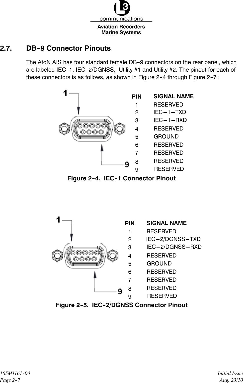


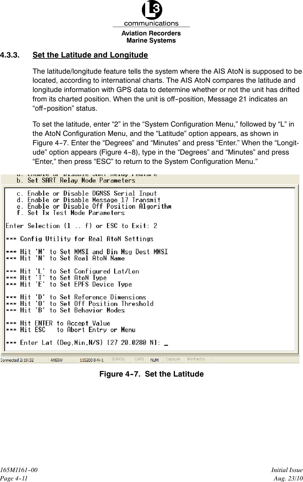
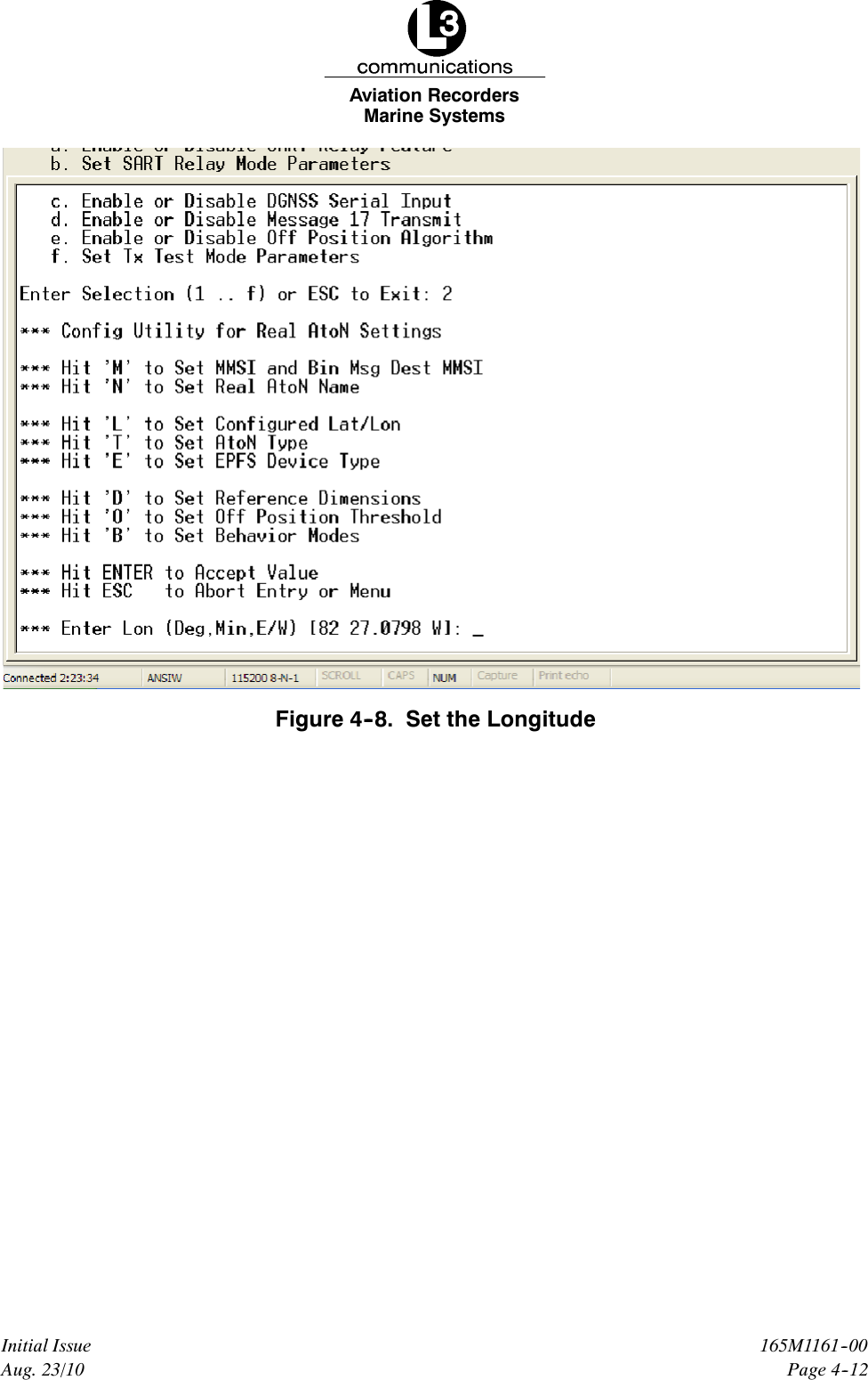
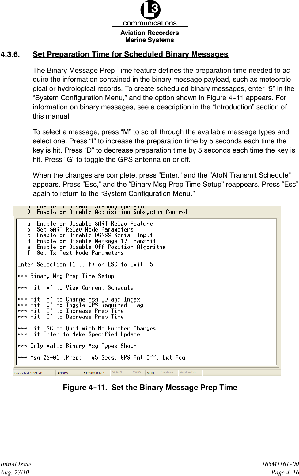
![Marine SystemsAviation RecordersPage 4--14165M1161--00Initial IssueAug. 23/104.3.5. Add or Replace Transmit SchedulesTo set the transmit data, enter “4” in the main “System Configuration Menu,” and thescreen in Figure 4--10 opens with the message “Adds or Replaces Schedule forSpecified MsgID.” Table 4--3 describes the configurable fields displayed in the lastline of the screen.Figure 4--10. Change the Transmit ScheduleTable 4--3. Transmit Schedule Setup Utility Field DescriptionsField KeyStrokeDescriptionFATDMA / RATDMA FEnables the user to toggle between the FATDMA andRATDMA formats[Add][Rplc][Del]ATells the unit that the user is either adding a new transmitschedule or replacing or deleting the existing schedule](https://usermanual.wiki/L3-Technologies/0ATN01.Manual/User-Guide-1347921-Page-40.png)
![Marine SystemsAviation RecordersPage 4--15Initial Issue165M1161--00Aug. 23/10Field KeyStrokeDescriptionTx TToggles between “Std” (Standard) and “Back2Back” formsof transmission; Typically set to “Std,” but special test sce-narios might require “Back to Back” transmissions[Slt 0009,Min1] “Shift”“+”Sets the slot on which to transmit the message; Press“Shift” and “+” (plus sign) key to increase the value of the“base” or “anchor” slot by increments of either 1 or 10, de-pending upon how the adjustment is set with the “Shift” and“*” keys[Slt 0009,Min1] “--” Decreases the value of the “base” or “anchor” slot by incre-ments of either 1 or 10, depending upon how the adjust-ment is set with the “Shift” and “*” keys[Slt 0009,Min1] “Shift” * Toggles the amount the base slot is adjusted between in-crements of either 1 or 10, allowing for fine control over theslot[Slt 0009, Min 1] U Changes the Universal Coordinated Time (UTC) by incre-ments of 1 minute, ranging from 0 to 9 minutesMsg MCycles through the message types to select a message toconfigure[10 Sec Ivl] IIncreases the time between message transmissions by cyc-ling the slot adjustment to within a range of 2 seconds and30 minutes (decreases the transmission rate)[10 Sec Ivl] DDecreases the time between message transmissions bycycling the slot adjustment to within a range of 2 secondsand 30 minutes (increases the transmission rate)Ch A Only / Ch B Only/ChA/BSpaceBarSelects the type of channel used to transmit the messageAction Key VDisplays a current view of the scheduleAction Key CClears all current reservationsAfter making a change and pressing the “ENTER” button, the “AtoN Transmit Sched-ule” appears with the message “Hit Any Key to Continue...” Press any key, and the“Transmit Schedule Setup Utility” screen reappears. Press “Esc” in the main “Trans-mit Schedule Utility” screen to return to the main “System Configuration Menu.”](https://usermanual.wiki/L3-Technologies/0ATN01.Manual/User-Guide-1347921-Page-41.png)