Maiden Rock Communications MRC565-40-43 Packet Data Radio Transceiver User Manual OPERATION AND MAINTENANCE
Maiden Rock Communications,LLC Packet Data Radio Transceiver OPERATION AND MAINTENANCE
Users manual
OPERATION & MAINTENANCE
OF THE
MRC-565 PACKET DATA RADIO
Rev. F
July 23, 2014
Maiden Rock Communications
PO Box 575
Seeley Lake, Montana USA
Tel: (207) 715 8242
2014 by Maiden Rock Communications
All rights reserved

Page 2 MRC-565 Packet Data Radio Operations & Maintenance
GENERAL WARRANTY
Maiden Rock Communications (MRC) warrants that its products conform to the published
specifications and are free from manufacturing and material defects for one year after shipment.
Warranty-covered equipment that fails during the warranty period will be promptly repaired at
MRC’s facility in Kent, Washington.
International customers are required to pay shipping costs to the MRC facility, with Seattle as the
point of U.S. entry. MRC will pay incoming U.S. duty fees. MRC will pay shipping costs to
return the equipment to the customer, with the customer paying all return duty fees.
This warranty is contingent upon proper use of the equipment and does not cover equipment that
has been modified in any way without MRC’s approval or has been subjected to unusual
physical or electrical stress, or on which the original identification marks have been removed or
altered.

Page 3 MRC-565 Packet Data Radio Operations & Maintenance
EXPOSURE TO RF RADIATION
The FCC guidelines limit the maximum permitted exposure to RF radiation for Occupational/
Controlled Exposure to 1 mw/sq. cm for frequency ranges of 30-300 MHz. This limit and the
following equation for calculating field strength (obtained from OET Bulletin 65) is used to
calculate the minimum separation between humans and the transmit antenna based on MPE
S= P*G* DC/(4**R*R)
P = Transmit power in milliwatts = 100,000
G = Antenna gain referenced to an isotropic radiator
= 1.68 (2.2dbi) mobile quarter wave dipole mounted to fender/roof of automobile
= 10.0 (10.0 dbi) fixed 5 element Yagi mounted to top of fixed antenna tower
= 3.3 (5.2 dbi) fixed half wave dipole mounted to fixed antenna tower leg
R = separation required cm
DC = Maximum duty cycle of transmitter = 10 %
S = Power density = 1 milliwatt/square cm
This equation is accurate for the far field of an antenna, but will over-predict power density in the
near field. Thus, the near field MPE distances calculated here are “worst case” or conservative.
Antenna separation for mobile applications:
The typical antenna used in mobile application has a maximum antenna gain of less than 2.2 dBi
(¼ wave dipole or ½ wave dipole). To insure safe operation the antenna must be mounted such
that the separation between the antenna and any human occupants of the vehicle exceeds .36
meters (14”). The best location for antenna mounting is the center of the vehicle roof. This will
provide additional RF shielding between the antenna and the human occupants that reduces the
RF exposure to levels well below that specified in FCC OET Bulletin 65.
When working on the antenna and or co-ax cable always disable the transmitter by turning its
power off.
Antenna separation for fixed applications:
For fixed applications, antenna gains and mounting techniques can vary depending on the
application. For Yagi antennas whose gain does not exceed 10 dBi, that antenna must be
mounted a minimum of .90 meters from any humans occupants. Lower gain antennas, such as
side mount dipoles, exhibit lower gain (5.2 dBi) allow closer separations (.52 meters for 5.2 dBi
antennas). This will provide RF shielding between the antenna and the human occupants that
reduce the RF exposure to levels below that specified in FCC OET Bulletin 65.
When working on the antenna and or co-ax cable always disable the transmitter by turning its
power off.

Page 4 MRC-565 Packet Data Radio Operations & Maintenance
REVISION PAGE
Document Title: Operation of the MRC-565 Packet Data Radio in a Meteor Burst Network
Document Number: MAN-OPS-MRC-565 – Meteor Burst
Revision #
Date
Revision
Redline
04/20/2014
Redline Release
Initial
05/10/2014
Initial Release
A
05/25/2014
Release A TD
B
7/23/14
Update format, references, TOCs (JW)
C
6/21/2014
Update format, references, TOCs (JW)
D
6/22/2014
Updated Theory of Ops TD
E
7/17/2014
Update format, TOC (JW)
F
G
H
I

Page 5 MRC-565 Packet Data Radio Operations & Maintenance
MCC 545B MRC-565 DIFFERENCES
There are several differences between the MCC 545B and the MRC-565. A summary of these
differences is given below:
Number of circuit boards MRC-565 has 2 MCC 545 has 3
MRC-565 is a software defined radio with no adjustments on CMU board
Both units have similar power amp boards
No battery backed up RAM. No PWR FAIL RESTORE message
New LPM modes
Ethernet Port with TCP/IP
USB Host Port for Thumb drive Logging and Data Storage
USB Device Port for connecting to PC USB port. Requires Driver
For the most part the MRC-565 operator commands are the same as the MCC 545B commands.
However, there are a few differences as noted below:
MCC 565
MRC 545
ASSIGN
ASSIGN
ASSIGN,RXn,CHAN,PROTOCOL
NONE
CHAN,TX,RX,MOD-VAL,CHAN
FREQ,TX,RX,CHAN
CHAN,N
FREQ,N
CHAN
FREQ
CAL
NONE
DSP
NONE
IP
NONE
IPCONFIG
NONE
FILE
NONE
FPGA
FPGA
LPM
LP[M
RECEIVERS
NONE
SCALE
SCALE
SP
NONE
SIG
NONE
RXTH
RXTH
TEST,TX
TEST,TX
TRACEERT
TRACEPORT
SDI12
NONE
In the cases where there are similar commands for the MCC 545 and MRC-565, the commands
are slightly different. Refer to APPENDIX C for details.
Page 6 MRC-565 Packet Data Radio Operations & Maintenance
TABLE OF CONTENTS
Title Page
EXPOSURE TO RF RADIATION ................................................................................................ 3
MCC 545B MRC-565 DIFFERENCES ......................................................................................... 5
1 INTRODUCTION ................................................................................................................ 14
2 NETWORKS ........................................................................................................................ 16
2.1 Meteor Burst Communications ..................................................................................... 16
2.2 Extended Line of Site Systems ..................................................................................... 17
2.3 Related Documents ....................................................................................................... 19
3 DESCRIPTION..................................................................................................................... 21
3.1 General .......................................................................................................................... 21
3.2 Printed Circuit Board Assemblies ................................................................................. 22
3.2.1 Communications Management Unit (CMU) ................................................................ 23
3.2.2 Power Amplifier (PA) ................................................................................................... 24
3.3 Detailed Specifications ................................................................................................. 24
3.4 Memory Organization ................................................................................................... 26
3.5 Front Panel LEDs .......................................................................................................... 27
4 INSTALLATION ................................................................................................................. 29
4.1 Cable Connections ........................................................................................................ 29
4.1.1 DC Power ...................................................................................................................... 29
4.1.2 VHF Antenna ................................................................................................................ 30
4.1.3 GPS Antenna (Optional) ............................................................................................... 30
4.1.4 I/O Port.......................................................................................................................... 31
4.1.5 USB-A Port ................................................................................................................... 34
4.1.6 Ethernet Port ................................................................................................................. 34
4.2 Power-Up Sequence ...................................................................................................... 35
4.3 Description of Critical Device Parameters for a MB Network ..................................... 36
4.3.1 Device ........................................................................................................................... 36
4.3.2 Role ............................................................................................................................... 36
4.3.3 Radio ID Number .......................................................................................................... 37
4.3.4 Frequency and Modulation Parameters ........................................................................ 38
Page 7 MRC-565 Packet Data Radio Operations & Maintenance
4.3.5 Select Site Name ........................................................................................................... 39
4.4 Enter Script Files........................................................................................................... 39
4.5 RF TEST ....................................................................................................................... 41
5 OPERATIONS ...................................................................................................................... 44
5.1 Getting Started .............................................................................................................. 44
5.1.1 Command Entry and Editing ........................................................................................ 44
5.1.2 HELP Command .......................................................................................................... 45
5.1.3 System Time and Date .................................................................................................. 45
5.1.4 Factory Default Parameters........................................................................................... 45
5.2 Configuring the MRC-565 Manually............................................................................ 46
5.2.1 Setting the Radio ID...................................................................................................... 46
5.2.2 Radio Frequencies and Modulation Format .................................................................. 47
5.2.3 Device Type .................................................................................................................. 48
5.2.4 Setting the Operating Role ............................................................................................ 49
5.2.5 Setting the Power Mode ................................................................................................ 49
5.2.6 Selecting Network Parameters ...................................................................................... 51
5.3 Local Area Network Configuration .............................................................................. 53
5.3.1 I/O Configuration Commands....................................................................................... 53
5.3.2 Scheduling MRC-565 Events ....................................................................................... 55
5.3.3 Setting Timeout Duration ............................................................................................. 56
5.3.4 Defining Data Relays .................................................................................................... 56
5.3.5 Scaling A/D Readings ................................................................................................... 57
5.3.6 Selecting the Burst Monitor .......................................................................................... 58
5.3.7 Controlling the Hourly Statistics Report....................................................................... 59
5.3.9 Power Turn On .............................................................................................................. 60
5.3.10 Saving and Restoring the Configuration ....................................................................... 60
5.4 Sending and Receiving Messages ................................................................................. 61
5.4.1 Entering and Deleting Messages ................................................................................... 63
5.4.2 Editing Messages .......................................................................................................... 65
5.4.3 Sending Messages ......................................................................................................... 65
5.4.4 Sending Remote Commands ......................................................................................... 66
5.4.5 Sending Canned Messages ............................................................................................ 66
Page 8 MRC-565 Packet Data Radio Operations & Maintenance
5.4.6 Receiving Messages ...................................................................................................... 67
5.4.7 Examining Message Status ........................................................................................... 68
5.4.8 Examining and Revising Message Queues ................................................................... 68
5.5 Sensor I/O Port .............................................................................................................. 69
5.6 Data Loggers Interface .................................................................................................. 70
5.7 CR10X Data Logger ..................................................................................................... 71
5.7.5 Update Interval.............................................................................................................. 75
5.7.6 Transmission Order ....................................................................................................... 75
5.7.8 Time of Day .................................................................................................................. 76
5.7.9 Time Tagging ................................................................................................................ 76
5.7.10 Memory Management ................................................................................................... 76
5.7.11 Data Scaling .................................................................................................................. 77
5.7.12 Modem Enable .............................................................................................................. 77
5.7.13 Setting/Reading CR10X Internal Registers .................................................................. 78
5.7.14 Entering CR10X Security Codes .................................................................................. 79
5.7.15 Downloading a CR10X .DLD Program ........................................................................ 79
5.7.16 Replacing an MRC-565 to an Operational CR10X ...................................................... 80
5.7.17 Replaying Data from a CR10X ..................................................................................... 81
5.8 CR1000 Data Logger .................................................................................................... 82
5.8.1 CR1000 Driver Configuration Command Summary: ................................................... 84
5.8.2 Acquire Mode: .............................................................................................................. 86
5.8.3 Data Retrieval Pointer Initialization ............................................................................. 86
5.8.4 Data Retrieval Hole Collection ..................................................................................... 87
5.8.5 Update Interval.............................................................................................................. 87
5.8.6 Transmission Order ....................................................................................................... 88
5.8.7 Group ID Assignment ................................................................................................... 88
5.8.8 Time of Day .................................................................................................................. 88
5.8.9 Time Tagging ................................................................................................................ 88
5.8.10 Memory Management ................................................................................................... 89
5.8.11 Data Scaling .................................................................................................................. 89
5.8.12 Modem Enable .............................................................................................................. 89
5.8.13 Reading CR1000 Internal Pointers and Error Statistics ................................................ 90
5.8.14 Displaying Status Table Data........................................................................................ 90
Page 9 MRC-565 Packet Data Radio Operations & Maintenance
5.8.15 Displaying and Setting Public Table Data .................................................................... 92
5.8.16 Downloading a Program ............................................................................................... 93
5.9 SDI-12 Sensors ............................................................................................................. 96
5.9.1 Data Collection ............................................................................................................. 97
5.9.2 Setup ............................................................................................................................. 97
5.9.3 Periodic Data Collection ............................................................................................... 98
5.9.4 Data Logging ................................................................................................................ 99
5.9.5 User Interface ................................................................................................................ 99
5.9.6 MRC-565 Commands ................................................................................................. 101
5.9.7 SDI, CMD, COMMAND TEXT ................................................................................ 103
5.9.8 SDI, TRACE, {OFF/ON} ........................................................................................... 103
5.9.9 SDI-12 Command/Response List ............................................................................... 104
5.9.10 Serial Port Command and Response Diagrams .......................................................... 105
5.10 Generic Data Logger ................................................................................................... 106
5.10.1 Typical Report Formats .............................................................................................. 106
5.10.2 Setup and Configuration ............................................................................................. 107
5.10.3 Viewing the generic device driver setup ..................................................................... 108
5.10.4 AUTO Format ............................................................................................................. 108
5.10.5 MULTI-LINE Format ................................................................................................. 109
5.11 Event Programming .................................................................................................... 112
6 Maintenance ........................................................................................................................ 116
6.1 Script Files .................................................................................................................. 116
6.2 Measuring Voltage Levels .......................................................................................... 116
6.3 Setting Up and Calibrating the MRC-565 Radio Parameters ..................................... 117
6.3.1 CMU Adjustments ...................................................................................................... 117
6.3.2 Power Amp Adjustments ............................................................................................ 118
APPENDIX A: COMMANDS ................................................................................................... 120
APPENDIX B: FACTORY DEFAULTS ................................................................................... 163
The following is a list of MRC 565 Parameters that are installed after typing: ....................... 163
To obtain a list of parameters settings in SCRIPT format for the MRC 565 type:..................... 163
APPENDIX C: EVENT PROGRAMMING .............................................................................. 168

Page 11 MRC-565 Packet Data Radio Operations & Maintenance
LIST OF FIGURES
Figure Page
FIGURE 1. MRC-565 PACKET DATA RADIO......................................................................... 15
FIGURE 2. EXPLODED VIEW OF MRC-565 ........................................................................... 21
FIGURE 3. MRC-565 WIRE DIAGRAM.................................................................................... 22
FIGURE 4. MRC-565 FRONT PANEL ....................................................................................... 27
FIGURE 5. MRC-565 CONNECTOR PANEL............................................................................ 29
FIGURE 6. DC POWER CONNECTOR ..................................................................................... 30
FIGURE 7. MRC-565 44 PIN I/O CABLE .................................................................................. 31
FIGURE 8. TYPICAL DATA ACQUISITION SYSTEM........................................................... 83
FIGURE 9. EXAMPLE SENSOR TABLE .................................................................................. 97
FIGURE 10. TEST BENCH CONNECTION DIAGRAM ........................................................ 100
FIGURE 11. DATA PORT BYTE STREAM TIMING AND DATA BYTE FORMAT .......... 105
FIGURE 12. CMU MRC 56500300-04 BLOCK DIAGRAM, CF PORTION ................ ERROR!
BOOKMARK NOT DEFINED.
FIGURE 13. CMU MRC 56500300-04 BLOCK DIAGRAM, RADIO PORTION ........ ERROR!
BOOKMARK NOT DEFINED.
FIGURE 14. CMU MRC 56500300-04 CMU LAYOUT ............ ERROR! BOOKMARK NOT
DEFINED.
FIGURE 15. DETECTED RF PLOT......................... ERROR! BOOKMARK NOT DEFINED.
FIGURE 16. TRANSMITTER BLOCK DIAGRAM ERROR! BOOKMARK NOT DEFINED.
FIGURE 17. POWER AMPLIFIER BLOCK DIAGRAM ........... ERROR! BOOKMARK NOT
DEFINED.
FIGURE 18. POWER AMPLIFIER LAYOUT......... ERROR! BOOKMARK NOT DEFINED.
FIGURE 19. TYPICAL REMOTE STATION WITH 3-ELEMENT YAGI ANTENNA ......... 199
FIGURE 20. MRC NETWORKS ............................................................................................... 202
FIGURE 21. NETWORK DOCUMENT TREE ........................................................................ 209
LIST OF TABLES
Table Page
TABLE 1. MRC-565 GENERAL SPECIFICATIONS ................................................................ 24
TABLE 2. MRC-565 RECEIVER SPECIFICATIONS ............................................................... 24
TABLE 3. MRC-565 TRANSMITTER SPECIFICATIONS ....................................................... 25
TABLE 4. MRC-565 MICROPROCESSOR SPECIFICATIONS ............................................... 25
TABLE 5. MRC-565 SCALING FACTORS ............................................................................... 57
ACRONYMS AND ABBREVIATIONS
A/D
Analog-to-Digital
ACK
Acknowledgement
ADC
Analog-to-Digital Converter

Page 12 MRC-565 Packet Data Radio Operations & Maintenance
AUX
Auxiliary Port
AVL
Automatic Vehicle Location
BPSK
Binary Phase Shift Keying
CR
Carriage Return
CSMA
Carrier Sense Multiple Access
DAC
Digital-to-Analog Converter
DMC
Data, Management and Control
DSP
Digital Signal Processing
DTA
Data Port
ELOS
Extended-Line-of-Sight
ETE
End-to-End Acknowledgement
GMSK
Gaussian Minimum Shift Keying
GPS
Global Positioning System
KBPS
Kilo (1,000) bits per seconds
LED
Light Emitting Diode
LOS
Line-of-Sight
MBC
Meteor Burst Communication
MBCS
Meteor Burst Communication System
MRC
Maiden Rock Communications
MNT
Maintenance Port
NMEA
National Marine Electronic Association
PC
Personal Computer
PCA
Printed Circuit Assembly
PCB
Printed Circuit Board
RAM
Random Access Memory
RF
Radio Frequency
RTCM
Radio Technical Commission for Maritime Services
RX
Receive
SCADA
Supervisory Control and Data Acquisition
SDATA
Sensor Data
SNP
System Network Parameter
SPDT
Single Pole Double Throw
TDMA
Time Division Multiple Access
TX
Transmit
UPDT
Update
UTC
Universal Time Clock
VSWR
Voltage Standing Wave Ratio
XTERMW
Terminal Emulator

Page 13 MRC-565 Packet Data Radio Operations & Maintenance
INTRODUCTION

INTRODUCTION
Page 14 MRC-565 Packet Data Radio Operations and Maintenance
1 INTRODUCTION
The MRC-565 Packet Data Radio can be used in Meteor Burst Communications (MBC)
networks or Extended Line of Site (ELOS) networks. Both networks are, packet switched,
digital data networks. MBC networks can operate at ranges up to 1200 miles, while ELOS
networks operate at ranges up to 100 miles, depending on terrain.
The MRC-565 can operate with two modulation formats:
1. Coherent BI Phase Shift Key (BPSK) Modulation operating at 4 KB/SEC. This format
matches the MCC 545B modulation format and is used in Meteor Burst Communications
Systems (MBCS). This format provides a more sensitive receiver (typically 6 DB more
sensitive than GMSK at 9.6 KB/SEC) required for good performance in the MBCS
2. Non Coherent Gaussian Minimum Phase Shift Key (GMSK) Modulation operating at 9.6
KB/SEC. This format matches the MCC 545C's modulation format and is typically used
in Extended Line of Site Systems (ELOS). It offers a higher thru put than the BPSK
modulation at the expensive of sensitivity.
The radio is FCC type accepted for operation with either modulation in Low Band VHF 40-50
MHZ band with an authorized bandwidth of 20 KHZ.
The MRC-565 is frequency synthesized. Three MRC-565 models cover the range of frequencies
from 40 to 50 MHZ. Each model has a unique FCC Type acceptance number as noted below:
MRC-565-40-43 Frequency Range 40-43 MHZ FCC ID 2ABUV-MRC565-40-43
MRC-565-43-47 Frequency Range 43-47 MHZ FCC ID 2ABUV-MRC565-43-47
MRC-565-47-50 Frequency Range 47-50 MHZ FCC ID 2ABUV-MRC565-47-50
Each model is unique and cannot be modified in the field. Once a unit has been set up as one of
the three models, it cannot be set to operate in another model's frequency range (prevented by
firmware), without returning to the factory for modification and recalibration.
In addition, radios are set up and calibrated at specific frequencies to match a customer's
authorized frequency or frequencies. Once calibrated, the authorized frequencies are locked into
the software and operation beyond the authorized frequencies is not allowed. If a customer
wishes to change his authorized frequencies, he must return the unit back to factory for
recalibration and possible model change.
Note: This equipment has been tested and found to comply with the limits for a Class A
digital device, pursuant to part 15 of the FCC Rules. These limits are designed to provide
reasonable protection against harmful interference when the equipment is operated in a
commercial environment. This equipment generates, uses, and can radiate radio frequency
energy and, if not installed and used in accordance with the instruction manual, may cause
harmful interference to radio communications. Operation of this equipment in a residential
INTRODUCTION
Page 15 MRC-565 Packet Data Radio Operations and Maintenance
area is likely to cause harmful interference in which case the user will be required to
correct the interference at his or her own expense.
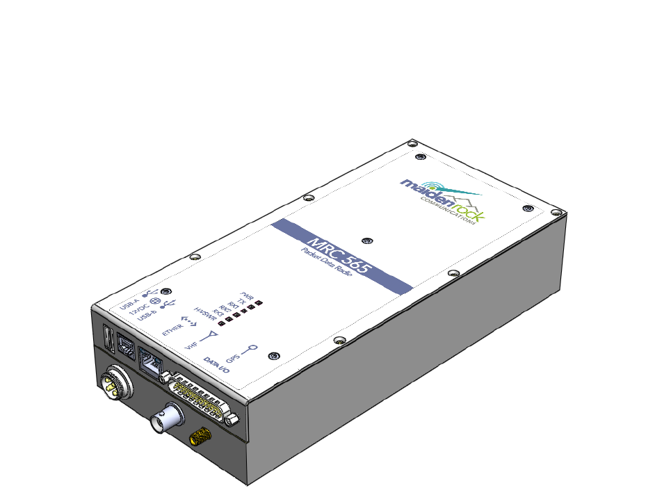
The MRC-565 is packaged in a aluminum, weather-resistant enclosure that measures 9.4”L X
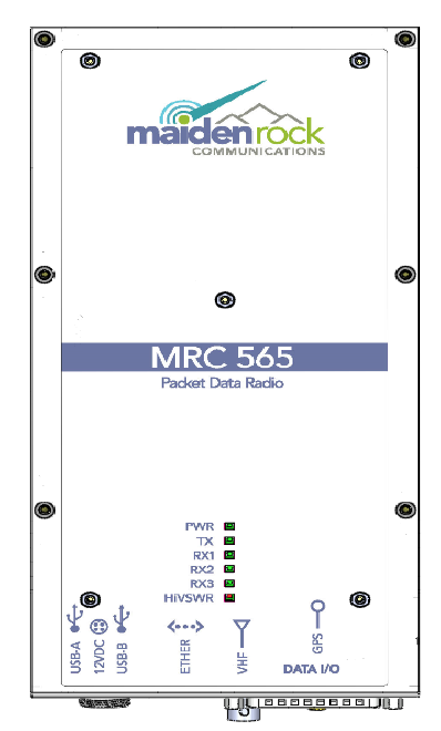
4.5”W X 2.00” H and weighs 3.5 pounds. A drawing of MRC-565 enclosure is given in Figure 1.
Figure 1. MRC-565 Packet Data Radio
The MRC-565 has two Printed Circuit Assemblies:
1. A Communications Management Unit (CMU)
The CMU contains an embedded 32-bit controller for managing all the network functions
associated with a packet switched data network and for interfacing to a variety of peripheral
devices. It also contains an RF Analog to Digital Converter (ADC), a Field Programmable
Gate Array (FPGA), an a Digital Signal Processor (DSP) to perform all receive and transmit
functions without the need for any Analog Signal Processing requiring physical tweaking or
adjustments. In addition, it has a built-in test capability that automatically monitors the
operating integrity of the unit at all times.
2. A 100 watt Power Amplifier (PA)
A power amplifier is used to boost the RF TX level of the CMU from 0 DBM to 50DBM
(100 watts) using a 5 stage power amp. This amplifier contains an agc that maintains a fixed
INTRODUCTION
Page 16 MRC-565 Packet Data Radio Operations and Maintenance
power level of 100 watts under varying DC voltage levels over a temperature range of -30 to
+60 C. As noted above the PA is factory tuned to operate over 3 frequency bands.
2 NETWORKS
2.1 Meteor Burst Communications
A meteor burst communication (MBC) network operates seamlessly between ground wave and
meteor burst for the transmission of digital data. Ground wave will generally cover distances up
to about 100 miles and meteor burst seamlessly extends this coverage to 1,000 miles. Ground
wave provides instantaneous communications while meteor burst reflects signals off the ionized
trails created by micro meteors entering the atmosphere at a height of 60 miles above the earth’s
surface. These trails, called bursts, are random but predictable in number, and last from a few
milliseconds to several seconds. During this brief period, information is exchanged between a
master station and a remote station. MBCS is a natural time division multiplexed (TDMA)
system, therefore thousands of remote stations can operate into one master station on a single
frequency.
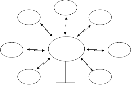
In its simplest form, a Meteor Burst network consists of one master station operating in a star
configuration to all remote stations located within its RF communication range of 1,000 miles.
The master station is an MRC-525 and the remote stations are MRC-565's or MCC MCC-545's.
The MRC-565 is a replacement radio for the earlier MCC MRC-545 which is out of production.
The master station is normally connected to a host computer in a Data Center or a customer’s
office. The master station operates on either a single frequency for half-duplex or two
frequencies for full-duplex.
The master station operates in the “probing” mode and the remote stations operate in the
“transponder” mode. That is, when a remote station hears a probe signal from the master station
it responds by transmitting the data stored in its buffer. The remote stations can be programmed
to respond at specific time intervals (e.g., hourly) or on events that may have occurred at the
remote station site. Programming may be done on-site with a laptop.
MASTER
STATION
REMOTE
REMOTE
REMOTE
REMOTE
REMOTE
REMOTE
REMOTE
HOST
INTRODUCTION
Page 17 MRC-565 Packet Data Radio Operations and Maintenance
The RF protocol for this type of network is called Meteor Burst Protocol (MBP). There are two
types of stations:
Master
Remote
Master stations and Remote stations are defined with:
ROLE = PROBE for Masters
ROLE=TRANSPOND for Remotes
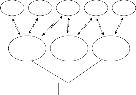
Multiple master stations are interconnected into a clustered star configuration as shown below.
The remote stations may be assigned to a specific master station or they can be programmed to
transmit their data to whichever master station probe is received. Multiple master stations will
significantly improve the latency of the network because of the additional RF links available to
each remote station.
2.2 Extended Line of Site Systems
The MRC-565 can also operate in Extended Line-of-Sight (ELOS) networks using ground wave.
The range of communication by ground wave is primarily determined by diffraction around the
curvature of the earth, atmospheric diffraction, and troposphere propagation.
The RF protocol for these types of networks is called Line of Site (LOS). All radios in these
networks are defined with:
ROLE = LOS
There are 4 types’ radios:
MASTER
STATION
REMOTEREMOTE REMOTE REMOTE REMOTE
HOST
MASTER
STATION
MASTER
STATION
INTRODUCTION
Page 18 MRC-565 Packet Data Radio Operations and Maintenance
Base
Repeater
Remote
The Base is always connected to a Host computer where data is being collected. Repeaters are
similar to Bases, but they do not have a Host connection. They repeat data collected from
Remotes to a Base which then sends the Data to the Host.
Remote stations connect to either a Base or a Repeater. When they have data to send in, they
transmit data directly to the Base of Repeater in carrier sense multiple access mode. They do not
wait for a probe from a Base or Master like a MB remote does.
The majority of this manual is devoted to Meteor Burst Networks. With a few Master Stations
and a lot of Remotes.
The remainder of this manual is organized in the following four sections
Section 3.0 DESCRIPTION
This section provides both a physical description and a functional description of each module
in the MRC-565. The detailed technical specifications for each printed circuit board
assembly (PCA) and the organization of the memory is provided.
Section 4.0 INSTALLATION
Site selection and general installation guidelines are provided in this section, including
instructions for cabling, antenna, and power source connections. Power up procedures,
initialization and functional test procedures are described that should be performed prior to
placing the MRC-565 on-line within the network.
Section 5.0 OPERATION
This section describes all the operating procedures for the MRC-565. All commands and
operational parameters are described for data collection, supervisory control, messaging and
interpreting system operational statistics. It also contains the list of all commands, along with
description and a few commonly used command printouts.
Section 6.0 THEORY OF OPERATION
This section provides overall review of the functioning of the CMU and the PA circuit board
assemblies. It describes the block diagram details of each printed circuit board.
Section 7.0 MAINTENANCE
APPENDIX A TABLE OF COMMANDS
INTRODUCTION
Page 19 MRC-565 Packet Data Radio Operations and Maintenance
APPENDIX B FACTORY DEFAULTS
APPENDIX C EVENT PROGRAMMING
APPENDIX E INSTALLATION DETAILS
APPENDIX E INTEROPERABILITY WITH OTHER MRC PRODUCTS
2.3 Related Documents
Additional documents and application notes that may be helpful in the operation of an MRC-565
Packet Data Radio are given below. They can be obtained from MRC.
1. Operations of the MRC-525 Operators and Maintenance Manual Rev. F, September 30
2013.
2. Application Note: CR10X Data Acquisition, January 25, 2014
3. Application Note: CR1000 Data Acquisition, February 23, 2014.
4. Application Note: SDI-12 Data Acquisition, May 24, 2014.

DESCRIPTION
Page 20 MRC-565 Packet Data Radio Operations and Maintenance
DESCRIPTION
DESCRIPTION
Page 21 MRC-565 Packet Data Radio Operations and Maintenance
3 DESCRIPTION
3.1 General
The MRC-565 Packet Data Radio provides packet switched communications from fixed sites to
a central Host. It can be used for data collection, supervisory control, sending and receiving
messages, or other custom applications. The unit's low standby-power consumption (<1 watt)
makes it ideal for operating in remote locations where only solar power is available.
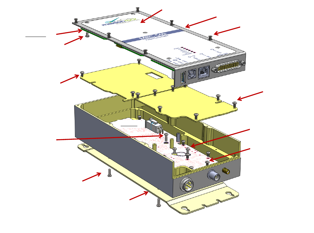
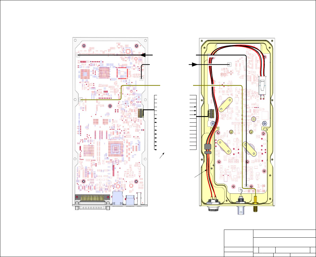
An exploded view of the chassis is shown in Figure 2. A simplified wiring diagram is shown in
Figure 3.
Figure 2. Exploded view of MRC-565
Qty6 –Flat head Stainless
4-40 x ¼” (MISC-1)
Qty5 - Pan head Stainless
4-40 x 3/16” (MISC-6)
Qty4 - Pan head Stainless
4-40 x 3/16” (MISC-3)
Qty1 –Lid Label (MISC-15)
Qty4 - Pan head Stainless
4-40 x 3/8” (MISC-4)
Qty8 - Pan head Stainless
4-40 x 3/16” (MISC-2)
Qty6 - Pan head Stainless
4-40 x 1/4” (MISC-5)
Qty9 - Pan head Stainless
4-40 x 3/16” (MISC-7)
Qty1 - Pan head Stainless
4-40 x 3/8” (MISC-8)
PA Lid2 (MetalWork-4)
PA Lid1 (MetalWork-3)
Mounting Plate
(MetalWork-5)
Enclosure
(MetalWork-1)
Lid (MetalWork-2)
CMU Board
PA Board
DESCRIPTION
Page 22 MRC-565 Packet Data Radio Operations and Maintenance
Maiden Rock Comm
MRC565 WIRING DIAGRAM
SIZE FSCM NO DWG NO REV
C
SCALE Not to scale SHEET 1 OF 3
J2
J1
J5
J3
J4
J15
J1
J4
J16
1 Gnd 20
2 Gnd 19
3 Gnd 18
6 PA-DC Enabled 15
7 PA-TX Key 14
8 PA RF Pwr Lvl Ctl 13
9 PA_VR 12
10 PA_VF 11
11 Gnd 10
12 12 VDC 9
13 12 VDC 8
14 PA HiVSWR 7
16 PA Power Good 6
18 PA_TX_Limit 3
20 PA_Temp 1
TX RF to PA (MRC56500803)
GPS RX (MRC56500802)
RX RF from LNA (MRC56500804)
J7
Data I/O J12
Ethernet
J14
USB-B
Slave
J13
USB-A
Master
12 VDC
Power Input VHF
40-50 MHz
GPS
PA–Power I/O Ribbon
(MRC56500805)
Power Cable (MRC56500801)
Figure 3. MRC-565 Wire Diagram
3.2 Printed Circuit Board Assemblies
The MRC-565 contains two printed circuit board assemblies as shown in Figure 2.
1. Communications Management Unit (CMU) MRC-56500300
2. 100 Watt Power Amplifier (PA) MRC-56500301
DESCRIPTION
Page 23 MRC-565 Packet Data Radio Operations and Maintenance
3.2.1 Communications Management Unit (CMU)
The CMU contains a Host Processor and a Software Defined Radio that contains a Digital Signal
Processor (DSP) . The Host processor is used to control the wire side protocols and interfaces as
well as the Over the Air protocols. The main microprocessor is a Motorola-based, embedded
processor located on a single PCB that contains:
512K x 16 of non-volatile flash memory for program storage
512K x 16 of non-volatile flash memory for parameter storage
32M x 16 of low power dynamic RAM for data storage
3 External RS-232 I/O ports
Ethernet Adaptor
USB-A Host Port for Thumb Drive Memory Devices
USB-B Device Port for connecting MNT port Laptop
Internal TTL GPS port GPS can be added to the CMU as an option.
Transmitter communication port
Receiver communication port
12-bit 16 channel A/D converter (6 channels are available for external sensors)
Real-time clock (w or w/o an internal battery)
Power fail detection circuitry
Digital Signal Processor with D/A converters
4 Optically isolated digital inputs
2 Solid State SPST Relay Outputs with a current rating of .5 amps
All I/O ports are RS 232 compatible (+/- 5V) and can be programmed to adapt to various
customer protocols. The DATA port contains full flow control hardware lines. The A/D
converter measures TX forward and reverse power, battery voltage, antenna noise voltage,
transmitter board temperature, and 6 channels of 0-5V external sensor inputs.
An internal battery is optional. This battery can be used to maintain the clock circuit whenever
power is removed from the unit. This battery is not required for operation of the unit. If the
battery is not present, it will be necessary to enter that date and time whenever the DC voltage is
removed from the unit. The low power modes will operate without the battery.
A Digital Signal Processor (DSP), a Field Programmable Gate Array (FPGA), a D/A converter,
and a A/D converter form the Software Designed Radio. The DSP is composed of a receiver
portion and a transmitter portion. The receiver RF signal is amplified and routed to the A/D
converter used to digitize the RF signal at the RF frequency. The FPGA provides a digital down
conversion (DDC) of the digital RF signal. The converted signals are fed to the DSP for
demodulation of the BPSK or GMSK signal.
The transmitter portion is implemented with an AD 9957 Quadrature Digital Upconverter
(QDUC). The AD9957 functions as a universal I/Q modulator and agile Upconverter. The
AD9957 integrates a high speed, direct digital synthesizer (DDS), a high performance, high
speed, 14-bit digital-to-analog converter (DAC), clock multiplier circuitry, digital filters, and

DESCRIPTION
Page 24 MRC-565 Packet Data Radio Operations and Maintenance
other DSP functions onto a single chip. It provides baseband upconversion for data transmission
in the Low Band VHF band. The RF output ( 0 DBM) is routed to the Power Amplifier (PA), via
a short coax cable.
3.2.2 Power Amplifier (PA)
A single power amplifier board is used to amplify RF output from the CMU board to the final
100 watt output. A special DC power switch is used to control the rise and fall times of the RF
power output. A duty cycle limiter circuit limits the duty cycle of the power amplifier to 10%.
A temperature sensor is also located on this board for monitoring the internal temperature of the
MRC-565. This temperature reading may be transmitted to the Host for maintenance purposes.
The 100 watt power amplifier is mounted inside an aluminum enclosure to provide RF shielding
between the CMU and the high power output. This board contains a T/R switch for half-duplex
operation, a harmonic low pass filter, and a dual directional coupler and AGC circuit for power
level control. The coupler measures forward and reverse power. If the VSWR exceeds 3.0:1, the
power amplifier automatically shuts down. The power amplifier’s parameters are also
transmitted to the Host for maintenance purposes. The antenna port of the T/R switch connects
directly to the COAX connector mounted on the MRC-565 front panel. The receive port of the
T/R switch is routed through a low pass filter to the Receiver COAX Connector. A short COAX
cable connects the PA receive port to the CMU receive port.
3.3 Detailed Specifications
The detailed specifications for each of the printed circuit board assemblies are given in Tables
2.1 through 2.4.
Table 1. MRC-565 General Specifications
CHARACTERISTIC
SPECIFICATION
Dimensions (excluding mtg braclet)
9.4”L X 4.5”W X 2.0”H
Weight
3.5 lbs.
Temperature Range
-30 to 60 C (-22 to 140 F)
Power Requirements
LPM = Low Power Mode
LPM,SP = Signal Present wake up
LPM,Alarm = DC PWR Alarm Clock wake up
LPM,PWR = No DC PWR Alarm Clock wake up
Cannot enter LPM,PWR unless TXQ empty
12 VDC Nominal (11-16 VDC)
Receiver Current
LPM,OFF 120 ma @ 13.0 VDC
LPM,SP: 80 ma @ 13.0 VDC
LPM,ALARM 65 ma @ 13.0 VDC
LPM,PWR 2 ma @ 13.0 VDC
Transmit Current
20 Amps Nominal (100 msec)
Table 2. MRC-565 Receiver Specifications
CHARACTERISTIC
SPECIFICATION
Frequency (Three models)

DESCRIPTION
Page 25 MRC-565 Packet Data Radio Operations and Maintenance
40-43 MHZ
43-46 MHZ
46-50 MHZ
+/-.0005% Synthesized 10KHz steps
Modulation: Type
Rate
Format
BPSK
4 kbps
NRZ
Noise Figure
< 7 dB minimum
Sensitivity: Bit Error Rate < 10-3 at 4 kbps
-120 dBm
IF Bandwidth (3/80 dB)
13/40 KHz typical
RF Bandwidth (3 dB)
13 MHz typical
Signal Acquisition Time
< 5 msec
3rd Order Intercept Point
>- 15 dBm
Image Response Attenuation
> 70 dB minimum
Spurious Response Attenuation
> 70 dB minimum
SP Threshold
Adjustable from –130 to –100 dBm
Noise Blanker
> 20 dB Reduction in Impulse Noise
I/O
MRC Standard (Refer to Section 3.2)
Table 3. MRC-565 Transmitter Specifications
CHARACTERISTIC
SPECIFICATION
Frequency (Three Models)
40-43 MHZ
43-46 MHZ
46-50 MHZ
+/- .0005% Synthesized 5KHz steps
RF Power Output
> 100 Watts at 12-16 VDC Input
Load VSWR
< 3:1 Rated Power (shut down if >3:1)
Harmonic Levels
70 dB below Unmodulated Carrier
Modulation: Type
Rate
Format
BPSK
4 kbps
Diff
Spurious
> 70 dB below Unmodulated Carrier
Transmit Modulation Spectrum
10 KHz offset – 25 dBC
50 KHz offset – 63 dBC
Tx Duty Cycle
10 % Max without shutting down transmitter
T/R Switch
Solid-State
Switching Time < 100 microseconds
I/O
MRC Standard (Refer to Section 3.2)
High VSWR Protection
Withstands Infinite VSWR
Table 4. MRC-565 Microprocessor Specifications
CHARACTERISTIC
SPECIFICATION
Main Processor
Motorola MC68332FC 32-bit Embedded Controller

DESCRIPTION
Page 26 MRC-565 Packet Data Radio Operations and Maintenance
Memory: Program Storage
Data Storage
Parameter Storage
512K x 16 non-volatile Flash memory
32M x 16 static Dynamic RAM
512K x 16 non-volatile Flash memory
Jumper: JP1
JP2
JP3
Watchdog Disable m(install to disable WD)
Ignition Bypass (install to disable IGN ON)
Power By Pass (Does not let 12V shut down)
3.4 Memory Organization
The MRC-565 has three types of memory:
Program Memory (PM): The Program memory is non-volatile Flash (512K X 16). It
contains the MBNET200 image software, bootstrap, configuration and application software.
These programs are installed at the MRC facilities at the time of shipment. The information
stored in the Program memory is referred to as “factory defaults”.
Parameter Memory (CPM): The Parameter memory is non-volatile Flash (512K X 16). It
contains the configuration data for the unit such as the customer number, the serial number and
ID of the MRC-565 and the authorized FCC frequencies it may use. This information is normally
programmed into the unit prior to shipment. The Script files are also stored in Parameter
memory, either at the MRC facilities or on site.
Data Memory (RAM): The Data memory is volatile Dynamic RAM (32M X 16). Date, time,
executable programs, command parameters and program dynamic data (messages, data, position,
etc) are all stored in RAM during normal operations.
During normal operation, the MRC-565 software uses the data and configuration parameters
stored in RAM. If the data information in RAM is lost or corrupted, for whatever reason, the
configuration parameters can be retrieved from Parameter memory. This ensures uninterrupted
operation.
The RAM contents will be lost under the following conditions:
1. The Boot command is issued.
2. Power is removed from the unit.
3. The watchdog timer initiates a restart.
The software will detect these events and will recopy the parameters and configuration values
from Parameter memory back into RAM when operation is resumed.
If the contents of Parameter memory become invalid, the unit will revert to the factory defaults
in Program memory.
DESCRIPTION
Page 27 MRC-565 Packet Data Radio Operations and Maintenance
3.5 Front Panel LEDs
The six LEDs on the front panel provide the operator with a quick assessment of the unit’s
operational status. See Figure 4.
PWR Flashes for about 2 seconds during power on. Then flashes once per second when SW starts
RX1,RX2,RX3 Flashes for 2 seconds on power up, then flashes whenever a signal is received
TX Flashes during Tx when the RF Output power is > 50 watts
HIVSWR Flashes during Tx when the VSWR > 3:1 is detected (means bad antenna, RF power turned off)
Figure 4. MRC-565 Front Panel

INSTALLATION
Page 28 MRC-565 Packet Data Radio Operations and Maintenance
INSTALLATION
INSTALLATION
Page 29 MRC-565 Packet Data Radio Operations and Maintenance
4 INSTALLATION
4.1 Cable Connections
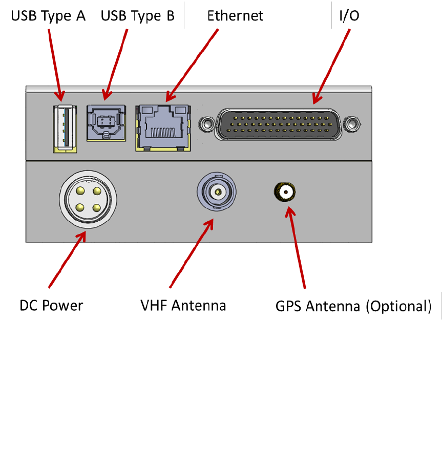
There are a maximum of seven cable connections to be made to the MRC-565 as shown in
Figure 5.
Figure 5. MRC-565 Connector Panel
4.1.1 DC Power
The MRC-565 requires a power source that can deliver up to 20 amps of pulsed power (100
msec) from a +12 VDC to +16VDC power source.
The 20 amp current draw will cause a voltage drop to occur at the transmitter input, resulting in
reduced transmit power, unless the power cable to the source is sized appropriately. MRC
recommends using two #16 AWG wires for both the power and ground and a cable length that
does not exceed 10 feet. If a longer cable is required, use #14 AWG. MRC provides a standard
INSTALLATION
Page 30 MRC-565 Packet Data Radio Operations and Maintenance
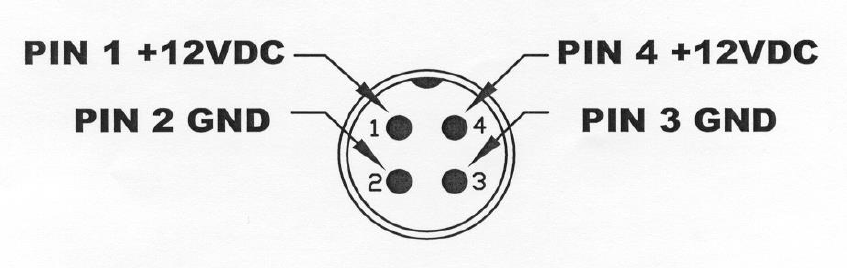
6 foot power cable with lugs for connecting to a 3/8" battery post (Part No. 14001350-01).The
power connector pins are shown in Figure 6 as follows:
Figure 6. DC Power Connector
Note the indent is at top of plug. The +12V inputs are on top side of connectors. Be careful not
to try an plug the cable into the connector in reverse order so that +12V is on bottom. If plugged
in backwards the +12V is shorted to ground (on PA board) and the DC line fuse will blow and
or a trace on the Power Amp board may burn out. Do not force.
4.1.2 VHF Antenna
Connect the antenna cable to the BNC RF connector. RG-223 may be used for cable lengths
under 50 feet. Use a large diameter cable (RG-214) for cable lengths up to 100 feet. Refer to
Appendix B for proper cable length.
4.1.3 GPS Antenna (Optional)
An external GPS antenna is required when the internal GPS receiver is used. Connect the GPS
antenna cable to the SMA connector on the front panel. The antenna port has a 3.3 VDC on the
center pin to power the GPS antenna,
INSTALLATION
Page 31 MRC-565 Packet Data Radio Operations and Maintenance
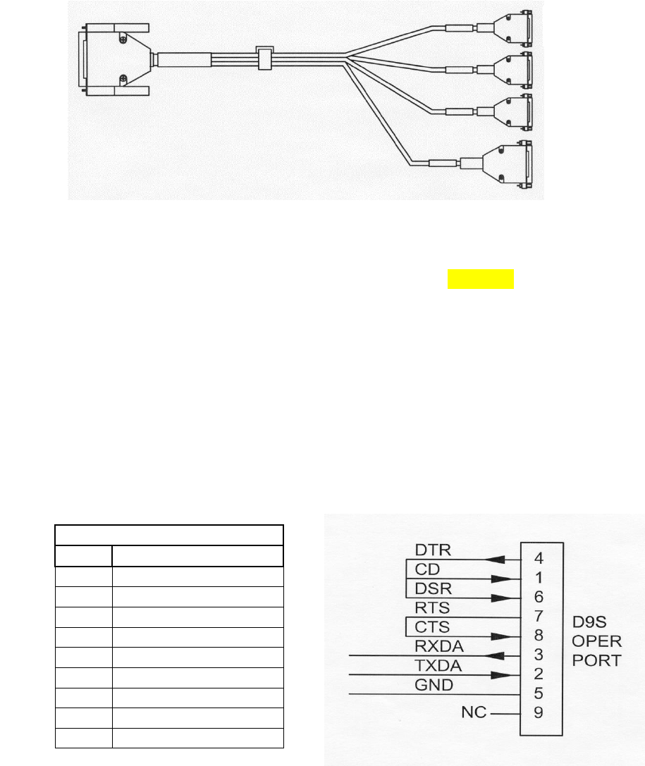
4.1.4 I/O Port
The 44 pin I/O connector on the front panel includes three RS-232 ports and one Sensor port.
MRC provides a standard cable harness that breaks out these four ports as shown below:
MRC-565 I/O Port Cable
Figure 7. MRC-565 44 Pin I/O Cable
A drawing showing the pin out for the 44 pin connector is given in Appendix below. A
description of each of the other connectors is given below. A description of the various ports is
given below.
4.1.4.1 Operator Port
The Operator Port is normally connected to a local operator terminal using a standard RS-232
straight thru cable with a 9-pin male D connector to 9-pin female D connector. Normally, only 3
wires (pins 2, 3 and 5) are required when connecting to the operator port. The port is wired to
support handshaking where required such as when using a modem. RS 232 levels are +/- 5V.
OPERATOR PORT – 9S
Pin
Signal
1
CD
2
Tx Data
3
Rx Data
4
DTR
5
Ground
6
DSR
7
RTS
8
CTS
9
Not Used
The Operator Port will display all warnings, messages, data report, and alerts.
I/O Port
(44 Pin)
Operator Port
(9 Pin)
Aux Port
(9 Pin)
Data Port
(9 Pin)
Sensor Port
(25 Pin)
INSTALLATION
Page 32 MRC-565 Packet Data Radio Operations and Maintenance
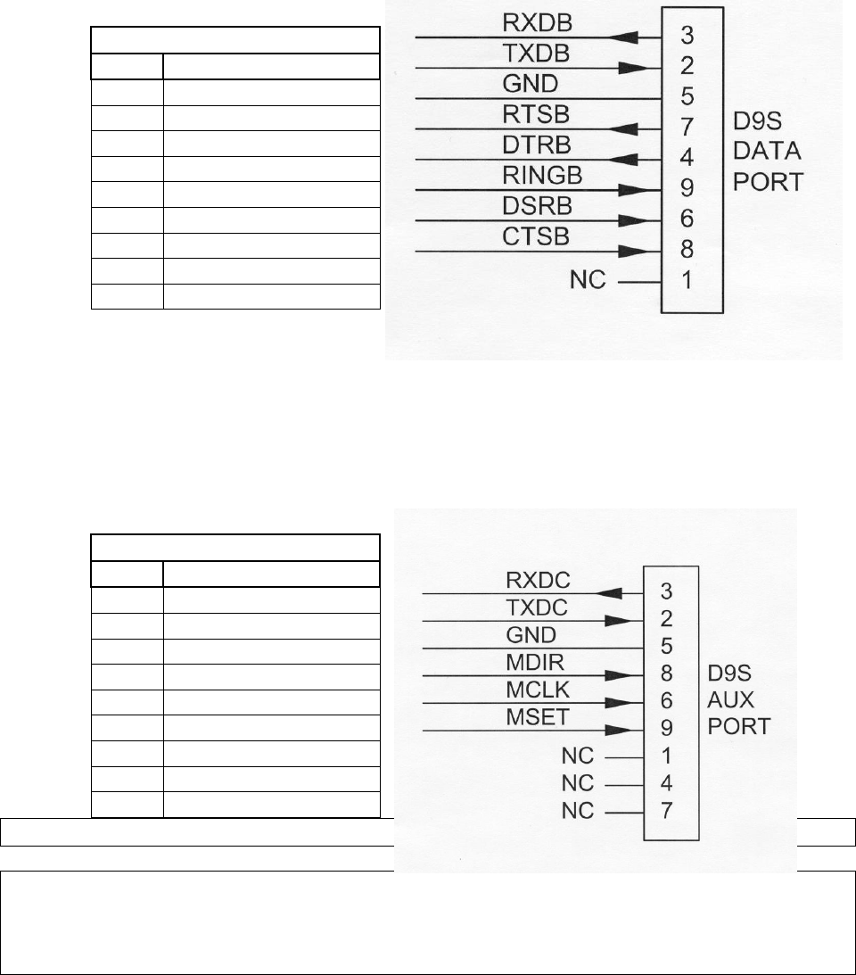
4.1.4.2 Data Port
The Data Port may be used for connecting to a data logger, GPS receiver or other serial input
device using a standard straight thru RS-232 cable with a 9-pin male D connector to 9-pin female
D connector. Refer to Section 4.0 for more information on interfacing to data loggers or other
serial input devices. All signals are RS232 (+/- 5V) levels.
DATA PORT – 9S
Pin
Signal
1
Not Used
2
Tx Data
3
Rx Data
4
DTR
5
Ground
6
DSR
7
RTS
8
CTS
9
Ring
4.1.4.3 Aux Port
The AUX PORT may be connected to any serial input device using a standard straight thru RS-
232 cable with a 9-pin male D connector to 9-pin female D connector. This port is also used for
interfacing to MRC test equipment (pins 6, 8, and 9).
UX PORT – 9S
Pin
Signal
1
Not Used
2
Tx Data
3
Rx Data
4
Not Used
5
Ground
6
MCLK (3.3V CMOS)
7
Not Used
8
MDIR (3.3V CMOS)
9
MSET (3.3V CMOS)
IMPORTANT
The AUX port connector has three extra pins (pins 6, 8, and 9) whose signals do not
conform to the RS-232 standard. These are for MRC test purposes. These pins will NOT
interfere with a normal 3-wire RS-232 connector (pins 2, 3, and 5).

INSTALLATION
Page 33 MRC-565 Packet Data Radio Operations and Maintenance
4.1.4.4 Sensor Port
The Sensor port is used as a general purpose Supervisory Control and Data Acquisition
(SCADA) interface requiring limited I/O in lieu of a full data logging capability. Use a mating
cable with a 25-pin male D connector for access to the various functions. For convenience, this
cable may be routed to a terminal block for interfacing to the various sensors and other external
devices. The Sensor Port contains:
SDI-12 Input/output and ground
Four (4) Optical Isolated Discrete Inputs. All 4 inputs share a common ground.
Two (2)Optical Solid State Switches which are normally open.
Six (6)Analog inputs
+12V Current limited to .50 amps
Switched + 12V Current limited to .5 AMP
TX Key Test Point
SP Test Point
A pin out of the Sensor Port is given below.
SENSOR PORT
Pin
Signal
1
Optocoupled input #1 positive
2K Input R, 2 V threshold
2
SDI-12 Data
3
Optocoupled input #2 positive
2K Input R, 2 V threshold
4
Optocoupled input #2 return
5
Optocoupled input #3 positive
2K Input R, 2 V threshold
6
Det RF for Chan #3
7
Optocoupled input #4 positive
2K Input R, 2 V threshold
8
Det RF for Chan #2
9
Ground
10
Solid State Relay #1 +
(.5 Amp rating)
11
Solid State Relay #1 -
12
Signal Presence (SP) 3.3V Logic
13
Solid State Relay #2 +
(.5 Amp rating)
14
Solid State Relay #1 -
15
TX KEY 3.3V Logic
16
+5V Reference (10 ma Max +/- 2%)
17
Analog Input #1 ( 0 to 5 V) 1%
18
Analog Input #2 ( 0 to 5 V) 1%

INSTALLATION
Page 34 MRC-565 Packet Data Radio Operations and Maintenance
19
Analog Input #3 ( 0 to 5 V) 1%
20
Analog Input #4 ( 0 to 5 V) 1%
21
Analog Input #5 ( 0 to 5 V) 1%
22
Analog Input #6 ( 0 to 5 V) 1%
23
+12V Switched (.5A Max)
24
+12V (0.5A Max)
25
Det RF for Chan #1
4.1.5 USB-A Port
A USB Host port can be used for storing TRACE log files or Data Reports. It can also be used as
a Configuration Management Unit (CIM) for reading and writing SCRIPT files.
4.1.6 Ethernet Port
An Ethernet Port that supports TCP/IP protocol is used to connect the MRC-565 to a wired Wide
Area Network (WAN). This eliminates the need for a router and terminal server to route data
back to a Host Computer.
There are two commands required to set up the Ethernet Port for operation. Enter the following
command to check the configuration:
IPCONFIG
the response will
The Ethernet port factory defaults to an IP address of
192.168.10.1
To change the IP address enter the following command
IPCONFIG,E1,nnn.mmm.ppp,qqq E1 is the Ethernet port.
To enable the port use the following command:
ASSIG,function1,n,protocol
where E1F1 is the function, n is the port number, and p is the protocl
The function can be ASCII,MSC,or MSC2
The port can be 4,5,6,or 7
A complete description of the TCP/IP protocol is given in Section .
INSTALLATION
Page 35 MRC-565 Packet Data Radio Operations and Maintenance
4.2 Power-Up Sequence
Connect a laptop, with XTERMW installed, to the Operator Port (MNT). The Operator Port
settings of the MRC-565 is programmed with the following factory default configuration at the
time of shipment:
Baud rate 9600
Data bits 8
Stop bit 1
Parity no
Protocol ASCII
Flow control none
When the unit first turns on after applying power the PWR, RX1, RX2, and RX3 front panel
LED's will turn on for about 2 seconds. This indicates that +12V is applied to the unit and that
the internal 3.3V regulators have turned on. At this point, the main control software is booting
up. After a few more seconds, the PWR LED will start flashing and the other LED's should turn
off. This flashing indicates that the main control software is running and the following messages
should be printed on the operator (MNT) port.
03/20/14 08:00:50 MNT port 0
/
/ / /
/ / /
*** O / O Maiden Rock Comm, LLC
******* O /\
/\ ********* /\/ \/\
/\/ ***********\/ \ / \
^^^^^^^^^^^^^^^^^^^^^^^^^^^^^^^
MRC-565 Packet Data Radio
Copyright (C) 2014 Maiden Rock Comm, LLC
All Rights Reserved
CMU Version 1.01.0057 03/15/14 07:30 AM
DSP Version 02.10 140221a_fc
FPGA Version 01.20 140216_ab
CPLD Version 43 01/27/14a
The software versions numbers for the CMU (Coldfire processor), DSP, FPGA, and the CPLD
are displayed. These numbers will change as newer versions of the software are developed. The
CPLD is an Altera Complex Programmable Logic Device. It is a single chip device used to
interface the various I/O functions with the Cold Fire Processor.
INSTALLATION
Page 36 MRC-565 Packet Data Radio Operations and Maintenance
With the exception of the CPLD, all versions of software can be updated via the Operator Port.
The CPLD requires direct connection of the Altera Blaster to the board.
4.3 Description of Critical Device Parameters for a MB Network
Most of the parameters used in a MB network do not have to be changed from there Factory
Defaults for normal operation. However, a few critical parameters must be set to obtain proper
operations. These are described below. These commands should be included in the SCRIPT
file used to program the unit as described in Section 4,4 below.
4.3.1 Device
The MRC-565 can be programmed to operate as a REMOTE, BASE, or MASTER. To check the
Device Type enter the following command:
DEVICE [ENTER]
If the device is not a REMOTE and you want to change it to a REMOTE enter
DEVICE,REMOTE [ENTER]
SAVE [ENTER] SAVE stores the Device type into FLASH memory.
The MRC-565 is always a REMOTE device in a MBC network. It may be any of the three
types in an LOS network.
4.3.2 Role
ROLE is used to set the Operating Mode and the RF Protocol for the device. There are four
modes:
PROBE Used if device is set up as a Master Station
TRANSPOND Used if device is a Remote Station in a MBC network
SILENT Used if device is set up to listen only (No Tx)
LOS Used if device is set up as a Remote Station in a LOS network
To determine the operating ROLE for the device type the following command:
ROLE [ENTER}
In a MBC network, the Role for all remotes is defined with the following command:
ROLE,TRANSPOND,High #,LOW#,MB for auto MB/LOS select.
INSTALLATION
Page 37 MRC-565 Packet Data Radio Operations and Maintenance
ROLE,TRANSPOND,MB for MB only
In the MB mode, the remote will respond to every idle probe from the Master and Transmit if it
has data to send Data or its time for it to check in.
When a Remote station is close to a Master station (<60 miles) the unit will probably hear the
Master station IDLE probe continuously. To prevent the Remote from responding to every Idle
probe (which occur about every 25 msec) the unit will automatically switch to a LOS mode. In
the LOS mode, the remote will not respond to every Idle probe, but will respond to every N
probes, where N is a Random number. The Random number prevents multiple remotes that are
operating LOS to the Master from interfering with each other. Note that LOS mode is not the
LOS protocol used in Line of Site only network.
The two numbers in the ROLE command are used to determine when a remote unit will switch
operation between MB and LOS. The high number is the number of Idle probes received per
minute it takes to switch from MB mode to LOS mode. The low number is the number of Idle
probes received per minute it takes to switch back to MB mode. The defaults settings for these
numbers is:
HIGH = 100
LOW = 50
Note that since the IDLE probes occur every 25 msec, there are 40 Idle probes per minute, so it
would take about 2 ½ minutes to switch to LOS protocol when default settings are used.
4.3.3 Radio ID Number
Every unit in a Meteor Burst Communications System has a 16-bit ID. This allows up to 65,536
unique ID numbers. The MRC-565 ID number will already be programmed into the unit by
MRC prior to shipment. Enter the command ID [ENTER] and the unit ID number will be
displayed on the operator terminal. Contact your System Administrator to register this ID in the
network configuration database. In some cases this number will be “locked” and cannot be
changed in the field, you can type LOCK to determine if the ID is locked or not.
Under some circumstances, the ID may have to be changed on-site. It can only be done if the ID
is not locked. In that event, this action must be coordinated with both MRC and your System
Administrator. Failure to do so may result in data or messages being misrouted or lost.
To change the ID use the following command:
ID,nnnnn,mmmmm{,aaaaaa},INIT [ENTER]
where nnnnnn is the unit ID, mmmmm is the master station assignment and aaaaaa is the
master select mode (FIXED, AUTO, PREF, MULTI). Obtain the proper master station
INSTALLATION
Page 38 MRC-565 Packet Data Radio Operations and Maintenance
assignment and select mode from your System Administrator. The MRC-565 will save this ID
and will use it whenever the unit is powered up or reset.
MODE
DESCRIPTION
PREF
Unit connects to the mmmm Master for the NDOWN period (set with SNP
command). After NDOWN period unit will connect to the Master that it has
received the most syncs from. In this mode the unit can communicate with only
one Master at a time.
AUTO
Unit connects to the mmmm Master, if it’s not successful it switches to another
Master. It will stay with that Master as long as it can communicate with it. In this
mode the unit can communicate with only one Master at a time. This is the
preferred mode for LOS networks
FIXED
Connectivity will be fixed to the mmmm Master. In this mode the unit can
communicate with only one Master at a time. This is the preferred mode for
networks with a single master.
MULTI
In this mode the unit can connect to any multiple Masters, This is the
preferred mode for Meteor Burst Networks. The format for this mode is:
ID,nnnnn,1,MULTI,INIT [ENTER]
You can also change the mode for the ID by typing
ID,aaaaaa
4.3.4 Frequency and Modulation Parameters
The MRC-565 will already be programmed with the authorized frequencies to be used in your
network. These frequencies are stored in parameter memory and cannot be changed. Verify that
the correct frequency is configured by entering the command:
CHANNEL (cr)
This will show you the “Active” TX and RX Frequency pair and frequency pairs for up to 20
channels that were programmed at the factory.
The following table will be displayed for the SNOTEL network:
+CHANNEL 01/01/00 01:08:29
Primary Channel TX mhz RX mhz Mod-Val Bit rate Modulation
07 41.6100 40.6700 1 4K bpsk25
Channel Table:
Channel TX mhz RX mhz Mod-Val Bit rate Modulation
INSTALLATION
Page 39 MRC-565 Packet Data Radio Operations and Maintenance
00 40.5300 41.6100 1 4K bpsk25
01 41.5300 41.5300 1 4K bpsk25
02 40.5300 41.5300 1 4K bpsk25
03 41.5300 40.5300 1 4K bpsk25
04 40.6700 40.6700 1 4K bpsk25
05 41.6100 41.6100 1 4K bpsk25
06 40.6700 41.6100 1 4K bpsk25
>07* 41.6100 40.6700 1 4K bpsk25
08 41.6100 40.5300 1 4K bpsk25
09 41.5300 40.6700 1 4K bpsk25
+
You can select any frequency pair from the frequency table by entering the following commands:
ASSIGN,RX1,n Where n is the channel number you want to assign to RX1.
CHANNEL, n Where n is the desired channel number
For example: To select channel 7 above enter:
ASSIGN,RX1,7
CHANNEL, 7
The active channel is the one with > in front and * after the channel number, 07 in this case.
The table above shows all the assigned channels and is Locked into each MRC radio before it
leaves the factory. Operation on channels beyond those listed is not possible without sending it
back to the factory for reprogramming.
4.3.5 Select Site Name
A descriptive name may be given to the site where the MRC-565 is being installed. The selected
site name must be coordinated with your System Administrator. To enter a site name use the
following command:
SITE NAME, XXXXXX [ENTER]
where XXXXXX may have a maximum of 32 alpha-characters.
4.4 Enter Script Files
The MRC-565 must be programmed with the parameters that “fit” the network that it is being
used in. This programming is accomplished by loading “Script file” from your PC into the MRC-
565 using the Operator (MNT) port. The Script File can also be downloaded into a Remote
Station via RF from the Master Station.

INSTALLATION
Page 40 MRC-565 Packet Data Radio Operations and Maintenance
If a script file have not been programmed into the MRC-565 and it must be changed, a new file
can be loaded from your operator terminal using XTERMW software. One script file uniquely
programs the MRC-565 to operate as a remote station in your specific network. Other script files
define application programs that are performed by the station.
For example, the application for a remote station may be as a mobile unit reporting position data
or as a fixed site reporting sensor data.
The procedure for loading the script file is described below:
1. Install the MRC-565 Meteor Burst CD (or diskette), with the script file on it, into your laptop
or equivalent, and load the script file into your XTERM subdirectory.
2. Start XTERMW and open a connection at the correct baud rate and COM port (typically
COM1, 9600 baud. All other parameters are defaults.
3. Type “factory,default,init” to load the default parameters into the MRC-565. The MRC-565
has a very large Flash memory for storing station parameters, as such it takes longer (90
seconds)to erase than it does to erase the MCC 545 flash memory (30 seconds)
4. Choose “Execute Script” from the “scripts” pull down menu.
5. Select the appropriate script file in the XTERM subdirectory. Double click the file name to
start execution.
The commands in the script file will be executed one at a time until the end of the file is reached.
Press the “up arrow” key to scroll up and review the command responses. If any commands
result in BAD COMMAND, BAD PARAMETER, or similar message, the script file may have
an error in it.
You may verify that the correct configuration file has been loaded by entering the three
commands: ASSIGN, SNP, and CONFIG. A typical script file for a remote operating in a
MBC network connected to a CR10X Data Logger is given below.)
IMPORTANT
The SAVE command must be performed at this time. Failure to do so will result in the loss
of any new configuration data in RAM that you may have entered during initialization.
The CONFIG command may be used to confirm that the MRC-565 has been configured
correctly for the network it is operating in. For example, if your MRC-565 is being used in a
Meteor Burst network the following configuration parameters will be displayed on your operator
terminal when you enter CONFIG [ENTER].
DATE
2/17/14
TIME
13:58:16

INSTALLATION
Page 41 MRC-565 Packet Data Radio Operations and Maintenance
DEVICE TYPE
REMOTE
ROLE
TRANSPOND,100,50,MB
ID
00500,00001,MULTI
DEFAULT DEST.
0
MODULATION
BPSK25
TRANSMIT KEY
STARTED
BIT RATE
4K
MESSAGE HOLD
OFF
DUPLEX MODE
HALF DUPLEX
SCHEDULE
ACTIVE or EMPTY
SERIAL
1
TX LIMIT
200
CHECK IN
900
STAT RPT INT.
24
LOS CHECKIN
5
DUTY CYCLE
10%
LOS RETRY
2
POS
30,TXT,NMEA
POLL
OFF
SOURCE RELAY
OFF
BASE
0,0
REPEATER
OFF
PULSE
OFF
POSRPT
OFF
HOURLIES
ON
NETMON
ON
ENTEK MDP
OFF
RCT
OFF
RXTYPE
MRC-565
REMOTE TYPE
COMM
SUBST
OFF
SCALE B: 0.062500, D: 0.018800, T: 0.000353
MAINTENANCE CONSOLE DEVICE
4.5 RF TEST
A very thorough RF test can be made by entering the command TEST [ENTER]. TEST causes
the processor to turn the transmitter ON and measures the forward and reverse RF power that is
being transmitted. It also measures the battery voltage under load and the antenna noise voltage.
The following response will be displayed on the operator terminal:
Syncs Xmits Acks pwr-fwd pwr-rev v-bat det-rf resets
XXXX YYYY ZZZZ AAAA BBBB CCC DDD EEE
where: XXXX = # of sync patterns received from the master station.
YYYY = # of transmissions made by the MRC-565.
ZZZZ = # of Acknowledgements received from the master station.
AAAA = Forward power in watts. This should be greater than 80 watts.
BBBB = Reflected power in watts. This should be less than 5 watts.
CCC = Battery voltage under load (while transmitting). This should be greater
than 10.6 VDC.
DDD = Received signal strength in dBm. This will normally be the noise level
at the antenna and should read about –120..
EEE Number of times the radio has rebooted.
NOTE
The forward RF power should be at least 80 watts if the battery voltage is normal. If it is
lower than 80 watts check for proper cabling to the power source. (see Section 3.2.2.1).

INSTALLATION
Page 42 MRC-565 Packet Data Radio Operations and Maintenance
If the reverse RF power is greater than 5 watts check the antenna and coaxial cabling for
proper installation.
If both the forward and reverse power are low, the transmitter may be automatically
shutting down due to an antenna VSWR greater than 3:1. Check the antenna and coaxial
cabling for proper installation.
If the DET RF is greater than –115 dBm (for example, -110 dBm), the unit will still
perform properly but the latency time of the link will be increased. Refer to Section 3.1 for
reducing site noise conditions.
An overall figure of merit for the link performance is the XMIT to ACK ratio. If this ratio
is 3:1 or lower, the overall performance will be very good.
This completes the initialization and power-up sequence of the MRC-565.The unit is now
ready for operation. Refer to Chapter 4 for detailed operating instructions.

OPERATIONS
Page 43 MRC-565 Packet Data Radio Operations & Maintenance
OPERATIONS
OPERATIONS
Page 44 MRC-565 Packet Data Radio Operations & Maintenance
5 OPERATIONS
This chapter covers the basic operating procedures for the MRC-565 as it's used in a Meteor
Burst network. The MRC-565 is programmed using Script Files that contain the specific system
parameters for operating in the meteor burst mode. These are loaded into the MRC-565 at the
MRC facilities prior to shipment. The script files may also be loaded and/or modified at the
customer’s site. You should always reset to factory default parameters by typing
FACTORY,DEFAULT,INIT prior to loading any new script files.
It is assumed at this point that the appropriate script file has already been loaded into the unit, as
part of the installation procedures outlined in Section 4.0, and that the unit is configured properly
and operational within its network. This chapter describes the various commands that are
available to the operator for modifying the station configuration parameters to accommodate
specific applications, sending and receiving messages and interfacing to peripheral devices for
data collection and supervisory control.
5.1 Getting Started
5.1.1 Command Entry and Editing
You must enter carriage returns after every command. A list of all the operator commands are
given in Appendix B
When a command is accepted, the operator terminal will print the system time.
Before you begin you should familiarize yourself with the special editing functions that you can
use when entering commands:
[DEL] Deletes last character entered.
[CTRL] Prints command line on next line down.
[CTRL]-R Repeats last command line
\X Removes current line from command buffer.
[CR], [LF] or [ENTER] Terminates line and causes the command entered to be executed.
OPERATIONS
Page 45 MRC-565 Packet Data Radio Operations & Maintenance
5.1.2 HELP Command
Entering HELP [ENTER] produces a single page display of all the commands used in the
operation and maintenance of the MRC-565. To obtain descriptive information about a particular
command and how it is used by the MRC-565 enter the command type. For example: HELP,
ASSIGN [ENTER].
5.1.3 System Time and Date
The MRC-565 has its own internal clock that is periodically synchronized to the nearest second
with the master station. The master station receives the correct date and time from either its
Host, GPS, or RTCM broadcast. The master station then periodically broadcasts this date and
time information to all remotes for synchronizing their internal clocks. If required, the date and
time may be initialized using the following commands:
DATE, mm/dd/yy [ENTER]
TIME, hh:mm{:ss} [ENTER]
In a Meteor Burst network the internal battery that is used to back up the Real Time Clock chip
is not installed so time and date must be entered at site whenever power is applied to unit. The
internal clock will be maintained during all Low Power Modes.
The date and time of day maintained in the Master Station (MRC-525 or the MCC 520B) is
transmitted to all Remote Stations between the times of 00:10:00 and 00:50:00 of each day, time
keeping all units in a network on the same time reference. If the time of day received at a
Remote Station differs by more than two minutes from the internal Remote clock, the Remote
will set its clock to the received time of day.
To manage time properly, each Master Station and Remote Station must know how its own time
zone relates to UTC and the system time. This relationship is established by relating its time
zone to known reference points. UTC is always referenced to GMT; however, system time can
be referenced to any desired time zone.
The time zone offset is defined with the following command:
TIME ZONE,UTC, Local Time Offset
Always set UTC Offset to 0, the local time offset should be set to the time zone offset (+/- TZ)
the remote station is from the master station time zone.
5.1.4 Factory Default Parameters
When you type
OPERATIONS
Page 46 MRC-565 Packet Data Radio Operations & Maintenance
FACTORY,DEFAULT,INIT
The unit restores the factory default parameters. A complete list of Factory Defaults is included
in Appendix B.
The station configuration parameters are usually entered by loading a configuration script file as
described in Section 4.4. It is also possible to enter these commands one at a time from the
operator port. This section describes some of the key commands. Refer to Appendix A for a
complete list of commands.
In order for the MRC-565 to operate correctly in your network, it must be properly configured.
Configuration requirements will vary from application to application, therefore refer to your
systems manual or consult your systems manager for correct settings.
Use the commands described in this section to set the configuration as per required. You may use
the CONFIG, ASSIGN, SNP and CR10X commands to verify proper configurations have been
set.
5.2 Configuring the MRC-565 Manually
The critical configuration parameters are:
Radio ID Sets unique radio up to 65,000
Channel Sets frequency, modulation type, and channel number.
Device Type Remote, Master, Base
Device Role Probe, Transpond, LOS, Silent
I/O Port Assignment//Drivers Port function, number, and protocol
Low Power Modes Power modes to reduce DC power used in receive modes
IP Configuration Ethernet Configuration
Parameters or operational states set by these commands are retained and will determine the way
in which the MRC-565 will interact with other equipment at the site and with the
communications network.
Most configuration parameters can be viewed with the CONFIG, ASSIGN, SNP and CR10X
commands. You should use these commands to verify that the configuration is correct. If it is not
correct, use the appropriate command(s) to correct the configuration, and then enter the "save"
command to write the configuration parameters into the CPM.
5.2.1 Setting the Radio ID
In command descriptions, the parameter "name" is the assigned Station name. The name is the
numeric Station ID. For more information on MRC-565C operation as either a Remote or Master
Station, refer to Section 4.2.1. Station IDs, represented by "nnnn", can be assigned as follows:
OPERATIONS
Page 47 MRC-565 Packet Data Radio Operations & Maintenance
2 – 254 Master Station
256 – 4095 Remote
Verify the ID is set correctly with the following command:
ID [ENTER]
If it is not correct, refer to Section 4.3.3 for instructions on how to set it.
This will show you the “Active” TX and RX Frequency pair and frequency pairs for up to 20
channels that were programmed at the factory.
5.2.2 Radio Frequencies and Modulation Format
As noted in Section 4.3.4 above, the MRC-565 will already be programmed with the authorized
frequencies to be used in your network. These frequencies are stored in parameter memory and
cannot be changed. Verify that the correct frequency is configured by entering the command:
CHANNEL (cr)
The following table will be displayed for the SNOTEL network:
+CHANNEL 01/01/00 01:08:29
Primary Channel TX mhz RX mhz Mod-Val Bit rate Modulation
07 41.6100 40.6700 1 4K bpsk25
Channel Table:
Channel TX mhz RX mhz Mod-Val Bit rate Modulation
00 40.5300 41.6100 1 4K bpsk25
01 41.5300 41.5300 1 4K bpsk25
02 40.5300 41.5300 1 4K bpsk25
03 41.5300 40.5300 1 4K bpsk25
04 40.6700 40.6700 1 4K bpsk25
05 41.6100 41.6100 1 4K bpsk25
06 40.6700 41.6100 1 4K bpsk25
>07* 41.6100 40.6700 1 4K bpsk25
08 41.6100 40.5300 1 4K bpsk25
09 41.5300 40.6700 1 4K bpsk25
+
You can select any frequency pair from the frequency table by entering the following commands:
ASSIGN,RX1,n Where n is the channel number you want to assign to RX1.
CHANNEL, n Where n is the desired channel number
OPERATIONS
Page 48 MRC-565 Packet Data Radio Operations & Maintenance
5.2.3 Device Type
The MRC-565 can operate as either a Remote Station, Master, or Base Station. Use the DEVICE
command to select the mode you require.
For normal MRC-565 Remote Station operation, enter:
DEVICE,REMOTE
As a Remote Station, the device will respond to Master Stations (usually MRC 525 or MCC 520)
every time they hear an IDLE probe. If they hear the Master IDLE probes continuously they will
revert to a pseudo Line of Site Role and limit how often they respond to the IDLE.. If the hear
the Master intermittently, they will operate in a Meteor Burst (MBC) role and generally respond
to all IDLE probes if they have something to transmit or its time for them to check in. Refer to
the command "ROLE" to set how and when devices choose a ROLE.
For MRC-565 operation as a Master Station, enter:
DEVICE,MASTER
As a MASTER the MRC-565 must operate in Halfduplex mode, with a delay between
transmissions of a t least 1000 msec.
For MRC-565 operation as a Base Station, enter:
DEVICE,BASE
BASE operation is used exclusively in ELOS networks. BASE stations are usually connected to
a back office host computer through a wired network connection (Ethernet)
Select the Operating Channel
As noted in the section above, the operating frequencies and modulation formats have already
been locked into the unit at the factory, according tour authorized operating channels.
OPERATIONS
Page 49 MRC-565 Packet Data Radio Operations & Maintenance
5.2.4 Setting the Operating Role
To see what ROLE the device is set to enter:
ROLE
In a MBC network, the ROLE is usually set to the following as described in Section 4. Above.
ROLE,TRANSPONFD,100,50,MB
A detailed description of the ROLE command is given in Section 4.3.2 above.
5.2.5 Setting the Power Mode
The MRC-565 has several power modes that determine the DC Power consumed when the unit is
in the non-transmit state. These modes do not affect the DC power consumed when in the
transmit state.
There are four Low Power Modes.
5.2.5.1 LPM,OFF
In this mode the unit operates without going to low power modes. A typical current draw for this
mode is about 130 ma, although during certain software functions the current may get as high as
180 ma. These function include FALSH download. The current can be reduced about 20 ma if
the Ethernet interface is not required. To turn off the interface use the turn off any ports that use
the Ethernet port using the ASSIGN command.
ASSIGN,E1F1,OFF
5.2.5.2 LPM,SP
In this mode, the CF and DSP processors operates in a low power mode. The receiver front end
is always active, and will produce an interrupt that wakes up the DSP when RF energy is
detected in the receiver bandwidth (10 kHz). When the DSP receives a wakeup interrupt, it will
demodulate the received signal and start looking for the Correlation pattern that is the front end
of all MBNET 200 data frames. When Correlation is detected, the DSP will wake the CF by
raising the DSP_SP. In this manner the MRC-565 can operate in a relatively low power mode
while still able to respond to received signals from the Master. Once the unit receives and
processes the Received data, it will go back to the LPM.
OPERATIONS
Page 50 MRC-565 Packet Data Radio Operations & Maintenance
It should be noted that unit will be in the LPM even if the TXQ has data to send. This means
there is relatively low receive current even when there is data to send as opposed to the MCC
545B LPM which operates at full receive current until all data is sent.
An interrupt timer is built into the hardware that wakes up the CF and DSP every 10 seconds.
This allows an operator typing on the keyboard (holding down the "period" key for about 10
seconds to wake the unit up. Applying an external voltage to the Ignition input (IN2+) can also
be used to turn on the power within 10 seconds of applying the voltage.
This mode has the advantage that the receiver is always active, which means that it can respond
to Master station Idle probes at any time. Wake up time to a receive signal is a few milliseconds
5.2.5.3 LPM,ALARM
This mode is the same at LPM,SP except that when there is no data to transmit, the entire radio
receiver is turned off, and current drops to about 50 ma. This mode also uses an interval timer to
wake up the CF processor every 10 seconds. In addition to the timer an internal alarm clock can
also be programmed to wake the CF up at a specific interval. Use the following command to set
an alarm clock interval:
PTW,NN
Applying an external voltage to the Ignition input (IN2+) can also be used to turn on the power
within 10 seconds of applying the voltage.
Where NN is a wake up interval in seconds. Wake up time from this mode is less than 1 second.
5.2.5.4 LPM,PWR
In this mode the CF is held in LPM,SP state until all data is transmitted. It then turns power off
to all internal circuitry except the Alarm clock. In this mode the internal timer is not power on,
so the only way to wake up the unit is to set the PTW to wake up the unit at a specific interval
using the following command:
PTW,NN
Where NN is the wake up interval.
In the is mode you must also set an power time out interval which turn power off:
PTO,XXX

OPERATIONS
Page 51 MRC-565 Packet Data Radio Operations & Maintenance
Where XX is the time before power is turned off.
You can also turn power onto to the unit by applying an external voltage(+3 to +12V) to the
Ignition input (IN2+) can also be used to turn on the power at any time.
A summary of the power modes and the expected current while operating in each mode.
MODE
DESCRIPTION
Current
WU TIME
LPM,OFF
LPM off with Ethernet on
130ma
NA
LPM,OFF
LPM off with Ethernet off
110ma
NA
LPM,SP
Rx on, CF halted, power on
75 ma
3 MSEC
LPM,ALARM
Rx off, CF halted, power on
50 ma
300 MSEC
LPM,PWR
Rx off, CF halted, power off
2 ma
3 SECONDS
5.2.6 Selecting Network Parameters
MRC recommends using the given default network parameters (values that are set on power-up
or after reset). If you choose to change these parameters, first review the discussion in this
Section and in Section 4.8.5, then use the following commands to change to the desired settings:
SNP{,pname,value}
where "pname" is the network parameter and "value" is a limit dependent on "pname". The
"pname" parameters are as follows:
TTL – Time-to-live in minutes (default is 120 minutes); this is the time limit for a message to
reach its destination before it is deleted from the queue.
The time-to-live parameter input is truncated to a 10-minute boundary. If you enter 60 through
69, the TTL for the next message will be 60 minutes. A resultant value of 0 (parameter range 0 –
9) means the message will never time out.
TTR – Time-to-retransmit in minutes (default is 30 minutes); i.e., the message is retransmitted if
it has not reached its destination within this time frame.
NUP – Neighbor-up threshold (default is 2 acquisitions); the number of times a Station must hear
from another Station within a one minute time interval before it becomes a neighbor.
NDOWN – Neighbor-down threshold in minutes (default is 120 minutes); if there is no
communication with a neighboring Station within the set time, the route to that neighbor is
ignored. Setting NDOWN to 0 maintains the routing to the neighbor indefinitely.
OPERATIONS
Page 52 MRC-565 Packet Data Radio Operations & Maintenance
RDOWN – Remote-down threshold in minutes (default is 2 minutes); if there is no
communication with a Remote Station within the set time, the Remote is declared down and is
removed from the Remote table. Setting RDOWN to 0 keeps a Remote defined indefinitely.
OTL – Outstanding text limit (default is 20 texts); the number of messages a Station is allowed
to send to another Station without an end-to-end acknowledgment.
CONNP – MASTER OPERATION ONLY - Connectivity message precedence (default is 1
precedence); information on changes in the connectivity table is given highest precedence
(automatic feature).
ETEAP – End-to-end ACK message precedence (default is 2 precedence); the
acknowledgment of a message when it reaches its final destination is given highest precedence.
HTO – History file timeout in minutes (default is 5 minutes); maintains information for
duplicate filtering.
TEXTL – MASTER OPERATION ONLY - Text size in segments (default is 32 segments).
FLOODP – MASTER OPERATION ONLY - Partial "flooding" precedence level (default is
A precedence). Messages of this precedence level and above are transmitted over all routes of
minimum length; messages below this precedence are not sent over all minimum length routes,
but are sent only over the routes where the shortest transmit queues exist.
MBHOP – meteor burst link hop weight (default is 1 hop). Defines the number of network
hops to associate with a meteor burst Master Station link when determining the minimum path to
use in routing a message. MBHOP should be set high enough to prevent a meteor burst Master
Station link to be chosen over a line-of-sight Remote to Remote link in a network that is
predominantly line-of-sight.
INF – MASTER OPERATION ONLY - Infinity hop quantity (default is 8 hops). Defines the
width of the network in hops plus one to determine when connectivity to a node is broken.
Should be as low as possible to minimize auto-connectivity traffic in the network, but large
enough to not erroneously flag nodes as being offline.
RELAY – MASTER OPERATION ONLY - Relay function specification (default is ON).
Specifies whether the MC-565 should act like a Remote in terms of relay functionality (i.e., does
not share connectivity table with other Masters.
DATAP – Priority of data reports initiated at the MRC-565 (default is Y precedence). When
used in any data collection network, this setting defines the precedence of data reports generated
asynchronously by the equipment itself. Typically, it should be lower than operator entered
messages and commands.
OPERATIONS
Page 53 MRC-565 Packet Data Radio Operations & Maintenance
5.3 Local Area Network Configuration
The MRC 525 has two groups of Network setup commands – IPCONFIG and the enhanced
ASSIGN commands. Each group of commands has several options, as shown below and in the
command summary table at the end of this chapter. The IPCONFIG commands set up IP
addresses for the Ethernet ports The ASSIGN commands were enhanced to include the Ethernet
and RX's. The RX port numbers are the Channel Numbers selected in CHANNEL command
With careful planning, MRC-525s can be configured in the shop and installed without needing
additional setup commands. The usual method, however, is to configure each site while the
technician is at the site, using pre-configured script files entered using XTERMW software. The
technician then verifies operation of each port before leaving the site.
A task in the MRC-525 then monitors each port once per second and establishes a connection
with the external equipment. Usually the RS-232 ports and Ethernet ports are permanent
connections that are always connected, but the external equipment may be powered on or off.
The monitor task will re-establish ports that are turned off when they come back on again.
It should be noted that the Ethernet port is non functional when operating in any of the Low
Power Modes (LPM) described in Section 5.2.5 above. Whenever any LPM are turned on, the
Ethernet Port will be placed in low power state. In addition removing Ethernet Port from the
Assign command will also turn the port off and place it in low power mode.
5.3.1 I/O Configuration Commands
5.3.1.1 Port Settings Using ASSIGN Command
The ASSIGN command is used to control the port settings and has been enhanced over the MCC
545B to include not only the serial data ports but also the Receiver and Ethernet ports.
ASSIGN Command Summary
ASSIGN, FUNCTION, PORT, PROTOCOL, TIMEOUT
where: Function = MNT, DTA, ALT, POS, (RS-232 Port Functions)
E1F1, E1F2, E1F3, E1F4, (Ethernet1 Functions)
RX1, RX2, RX3 (RF Receiver Functions)
Port = 0, 1, 2, 3 (RS-232 ports)
4, 5, 6, 7 (Ethernet1 Ports)
0, 1, 2 (Rx Channels)
Protocol = ASCII, MSC, MSC2, CR10X, CR1000, MBNET, PKT, PAKBUS,
SERPKT, APCL5, GPS, RTCM, M12RTCM,
OPERATIONS
Page 54 MRC-565 Packet Data Radio Operations & Maintenance
M12DIFF, TRAN, UAIS, GYRO, SOUNDER, PHAROS, H350,
DIRECT, GENERIC, AEI, HOTBOX, DRIVERs.MPL
Timeout = Optional timeout value in seconds.
Examples: ASSIGN, DTA, 1, MSC2, 5
ASSIGN, E1F1, 4, ASCII, 30
ASSIGN,RX1,0 where the last number is the channel number described above.
ASSIGN.ALT,2,IPC1
ASSIGN,POS,3,IPC2
A typical printout from entering:
ASSIGN.
Task Port Protocol T/O Type State Baud P D S F IP Address Port TP PT
----- ---- ---------------- --- ---------- ---------- ------ - - - - ---------------- ----- -- --
MNT 0 ASCII 30 SERIAL Open 9600 N 8 1 N *
ALT 2 IPC1 30 SERIAL Connected 115200 N 8 1 N
DTA 1 MSC2 30 SERIAL Open 9600 N 8 1 N
POS 3 IPC2 30 SERIAL Connected 115200 N 8 1 N
E1F1 4 ASCII 30 ETHERNET Connected 192.168.10.1 04000
FTRC 12 TRACEFILE 30
RX1 00 MBNET LB VHF
RX2 01 MBNET LB VHF
RX3 02 MBNET LB VHF
5.3.1.2 Ethernet Port Configurations Settings
The IPCONFIG commands is used to set up IP address for the Ethernet port.
IPCONFIG Command Summary Description
IPCONFIG Display IP Settings
IPCONFIG,ALL Display ipconfig, arp and routing
IPCONFIG,{E1},OFF Disable Operation on a port
IPCONFIG,PORT,192.168.16.30 Enable operation , supply IP address
IPCONFIG,PORT,DHCPC,{ON,OFF} Enable/Disable DHCP Client on a port
IPCONFIG,GATEWAY,192.168.16.2 Define IP Gateway for all ports
IPCONFIG,SUBNETMASK,255.255.255.0 Define subnet mask
IPCONFIG,MAC1,00-CF-54-85-CF-00 Enter port 1 MAC Address
The MRC 565 has one Ethernet Port, E1. You can connect to the Ethernet Port by connecting a
laptop computer’s Ethernet port to the front panel Ethernet Connector. Use the Operator RS232
Port to set the IP as shown below.
IPCONFIG,E1,192.168.10.1 Factory default
Set the IP address of the Laptop to a fixed address:
OPERATIONS
Page 55 MRC-565 Packet Data Radio Operations & Maintenance
IP ADDRESS 192.168.10.10
MASK 255.255.255.0
GATEWAY Don’t care
Before you can connect to an Ethernet Port, ensure that an Ethernet Port is assigned using the
following command.
ASSIGN,E1F1,4,ASCII,30
This assigns Ethernet Function E1 to Port 4 using ASCII protocol. Note that this port is not the
MNT function.
You can now start XTERM. In XTERM:
Select Device Type MCC 6100 SDR.
Set to connect to IP 192.168.10.1
Set the Port Number to 4000
An Ethernet connection to the MRC 565 is much faster than the RS 232 ports and really speeds
up the download of the Operating System (OS) software.
5.3.2 Scheduling MRC-565 Events
The SCHED command allows you to schedule automated command "events". An "event" simply
consists of giving one or more commands a trigger time. When the MRC-565's real-time clock
reaches the trigger time, the scheduler invokes the command as though you had entered it from
the MRC-565's operator terminal.
Two different types of time trigger options are provided for command scheduling: INTERVAL
and TIME. The INTERVAL trigger allows you to schedule a command to be invoked at
periodic intervals within a 24-hour time period; the TIME trigger allows you to schedule a
command to be invoked only once at a specified point within a 24 hour period. The command
schedule list is restarted each time the real-time clock reaches midnight.
To display the current schedule list, enter:
SCHED
To add a new command to the schedule list, enter:
SCHED,type,time{OFFSET,time},command
OPERATIONS
Page 56 MRC-565 Packet Data Radio Operations & Maintenance
where: type = INTERVAL or TIME (I or T)
time = hours:minutes:seconds
OFFSET,hh:mm:ss = time offset from specified timeframe (optional)
command = any MRC-565 command (with parameters)
To remove command event(s) from the schedule list, enter:
SCHED,DEL,xxx
where: xxx = ALL (erases entire schedule)
or
= schedule list number (removes single scheduled event from the schedule list)
You can schedule several command events to trigger at the same time, however, you cannot
force one command to execute before or after another. After assigning command events to the
schedule, the order of commands displayed in the schedule list is the order in which the events
will trigger for any given trigger time (i.e., an event with a low schedule number occurs before
an event with a higher schedule number).
5.3.3 Setting Timeout Duration
There is one programmable time limit for the I/O port input on the MRC-565. MRC
recommends using the pre-programmed default timeout parameter. If you choose to change the
timeout the time limits may be set by entering the number of seconds, from 0 to 32767. Enter a 0
to turn off the time limit.
Command Description
STT,secs The Set Teleprinter Timeout command sets the time limit for characters at the
maintenance terminal. Default is 60 seconds (1 minute).
5.3.4 Defining Data Relays
The ambient noise conditions at a remote station site may sometimes be excessive and a poor
communication path to the Master Station will result particularly if the remote station is
operating in a meteor burst mode. To overcome this problem, another MRC-565 may be placed
in a nearby quiet location and used as relay station between the MRC-565 at the noisy site and its
master station. When used as a relay, the MRC-565 will concentrate the data reports it receives
from one or more neighboring remote sites and forwards the data to the Master Station.
In this mode, the MRC-565 must be defined as a Master Station. The relay will then receive
Group data reports from other MRC-565 units located in noisy or un secure locations and
repackage them and forward them to the Master Station. A relay can handle sixteen GROUP
reports. These reports can be in any combination; i.e., four groups from each of four Remote
units, one group from each of sixteen Remote units or any combination in between. Substitution
OPERATIONS
Page 57 MRC-565 Packet Data Radio Operations & Maintenance
tables must be established in both the relay unit and at the Master Station to manage the relay
function.
When a designated GROUP report is received at the relay, it will substitute its own ID and group
number in the report as defined in its substitution table and forward the data to an MRC-520B
Master Station using the MRC-550C RF format rather than the standard MRC-565 message
format. When the relayed data is received at the MRC-520B it reconstructs the original data
report based on its own substitution table and route the report as required.
The following command is used to define the entries in the substitution table for a relay unit:
SUBST,relay_id,relay_group,remote_id,remote_group
where: relay_id is the relay unit's ID
relay_group is the data group report number at the relay
remote_id is the originating Remote unit's ID
remote_group is the data group report number at the originating Remote unit
5.3.5 Scaling A/D Readings
The MRC-565 contain a 12 bit A/D converter that is used to measure 16 analog voltages input
including:
Battery Voltage 0- 20VDC
Power Amplifier Forward Voltage VF VF = 5.2 V when Power = 100 watts
Power Amplifier Reverse Voltage VR
Power Amplifier Temperature
Six Internal Regulated Voltages
Six External Voltages (ADC1 – ADC6)
Table 5.2-1 below lists the various parameters.
The MRC-565 automatically converters the raw readings from its A/D converter to calibrated
engineering units for operator use. The scale factor and offset values for the first ten parameter
are preset in the software and should not be changed. The final 6 parameters are external
parameters that are input through the I/O connector. (Refer to Section 4.4.1.4)
Entering the following command will produce a table of A/D readings along with their scale and
offset values as well as Raw and Cal values for each parameter
SCALE
16 parameters are read by the A/D converter as noted below.
Table 5. MRC-565 Scaling Factors

OPERATIONS
Page 58 MRC-565 Packet Data Radio Operations & Maintenance
CHAN
SCALE
OFFSET
RAW ADC
SCALED ADC
VBAT
0.0048800
0.0000
2551.0000
12.448880
PA_VF
0.0000221
0.0000
0.0000000
0.000000
PA_VR
0.0000221
0.0000
0.0000000
0.000000
PATEMP
0.2250000
-58
3.3V
0.0012207
0.0000
2695.0000
3.2897865
1.8V
0.0012207
0.0000
1454.0000
1.7748978
1.5VCFC
0.0012207
0.0000
1134.0000
1.3842738
3.3DSP
0.0012207
0.0000
2675.0000
3.2653725
1.6DSPC
0.0012207
0.0000
1256.0000
1.5331992
1.2VFPGAC
0.0012207
0.0000
967.00000
1.1804169
ADC1
1.0000000
0.0000
0.0000000
0.0000000
ADC1
1.0000000
0.0000
0.0000000
0.0000000
ADC1
1.0000000
0.0000
0.0000000
0.0000000
ADC1
1.0000000
0.0000
0.0000000
0.0000000
ADC1
1.0000000
0.0000
0.0000000
0.0000000
ADC1
1.0000000
0.0000
0.0000000
0.0000000
Scale factors and offset values are dependent on the range of input voltages for these parameters.
The input voltage at the I/O connector must not exceed 5.00 VDC. A 12 bit A/D converter is
used to convert the input voltage to a digital value from 0 to 4095. Scale Factor is set using the
following formula:
Scale Factor = (5.0/4095) *1/INPUT DIVIDER = .0012207 * 1/INPUT DIVIDER
Where the INPUT DIVIDER is the voltage attenuator at the ADC input required to keep the
maximum input voltage below 5.00 VDC
Use the following command to change scale and offset values for each of the external inputs:
SCALE,ADCn,SCALE,OFFSET
5.3.6 Selecting the Burst Monitor
The MRC-565 has a unique meteor burst monitoring capability that allows monitoring the
number of characters received, the RF signal level and other parameters on each reception.
To turn on the burst monitor and to record statistics on a meteor burst link, type:
MON{,d{,r}}
The two optional parameters are designed to limit the printout. The burst monitor generates two
or three lines of printout for every burst. This could conceivably create hundreds of pages of

OPERATIONS
Page 59 MRC-565 Packet Data Radio Operations & Maintenance
printout a day in a network environment. The first parameter is the duration character count
limit. Only meteors lasting long enough to deliver "d" characters will be monitored. The second
parameter is the received character count limit; if at least "r" characters are received on the burst,
a monitor line will be generated. The default values are 100 for "d" and 1 for "r". For example, to
limit the printout, but still receive some maintenance benefit from the monitor, enter:
MON,500,100
This will limit the printout to meteors that have a duration character count greater than 500, or a
received character count greater than 100. These parameters may be adjusted as desired.
The command MONOFF turns off the burst monitor
5.3.7 Controlling the Hourly Statistics Report
By default, an hourly statistics report is generated on the maintenance terminal port on the hour.
This report consists of the same statistic reports generated by the BINS, MEM, and STAT
commands.
The hourly report can be disabled by entering the command:
HOURLIES,OFF
The hourly report can be re-enabled by entering the command:
HOURLIES,ON
5.3.8 Reading Internal Sensor Values
The MRC-565 radio has the capability to read certain sensor values, e.g. Internal rechargeable
battery (-03 only), internal temperature, etc.
Following are the most commonly used commands to read these sensor values, please note that
some commands are only available on -03 radios. For a more detailed description of this feature,
refer to Section 4.7.
COMMAND
DESCRIPTION
EVENT,STATUS,PATEMP
Reads the internal PA temperature of the unit
EVENT,STATUS,BAT
Reads the unloaded battery (external) of the radio
EVENT,STATUS,LBAT
Reads the loaded battery (external) of the radio
EVENT,STATUS,ADC1 { thru DC6}

OPERATIONS
Page 60 MRC-565 Packet Data Radio Operations & Maintenance
5.3.9 Power Turn On
The MRC-565 has the ability for the radio to be powered off by the CF Processor. This can be
used to turn the radio off under electronic control for purposes of reduction standby operating
current.
An external control signal (e.g. car ignition, data logger, etc) connected to the I/O port is used to
turn the unit on.
This external signal (+3 to 12VDC voltage) is applied to the optical isolated port 2, available on
the 25 pin connector (I/O Port). There is an internal 2000 ohms resister to limit the current. To
connect the control signal to IN2, apply +V to IN2+ (Pin 3 on DB-25 connector) and –V
(ground) to IN2- (Pin 4 on DB-25 connector).
To enable the power off feature, use the following command to set the Power Time Out (PTO)
in seconds to turn the radio off after the IN2 is removed.
PTO,xxx where xxx is the timeout in seconds.
NOTE
PTO command must not be used (i.e. set to PTO,OFF) if JP2 is installed.
5.3.10 Saving and Restoring the Configuration
To aid your understanding how the MRC-565 operational configuration is saved and restored it
is helpful to understand the hardware and design philosophy of the MRC-565.
The MRC-565 is designed to operate unattended in a variety of environments where power may
be applied continuously or intermittently. The goal is for the unit to continue to operate without
loss of messages, data or configuration even if power is randomly turned on and off. Therefore
the software is designed to operate continuously, to save all operational information when power
is off and to resume operation from that point when power is restored.
To support this philosophy, the MRC-565 has three types of memory:
PROGRAM MEMORY (PM)
CONFIGURATION PARAMETER (CPM)
RAM
The PM is non-volatile flash memory that has been programmed with the MRC-565's
operational software (OS). This software contains the initial values of all operational parameters.
The values are referred to as the "factory defaults" because they are programmed into the MRC
MRC-565 operating system software at the factory. The PM can only be modified by replacing
the operating system using the flash download. (Consult XTERMW manual to learn how to
download a new flash into the PM.)

OPERATIONS
Page 61 MRC-565 Packet Data Radio Operations & Maintenance
The RAM contains all the dynamic data for the MRC-565. All data logger data, positional data,
and messages entered into the MRC-565 are stored in RAM. Also, all command parameters are
stored in RAM. But RAM is volatile and can only retain information while power is applied.
Turning off or disconnecting power will cause all RAM information to be lost.
During normal operation, the MRC-565 software operates from the data and the parameters that
are stored in RAM. Unfortunately, there are always situations when the RAM data may be lost
or corrupted due to total discharge of the battery, software crash or operator error. Since we do
not want to lose our configuration data during these situations, we have a third type of memory.
The third type of memory, CPM, is also nonvolatile flash memory and retains data even when
power is removed. The MRC-565 retains a copy of all the programmed configuration parameters
in CPM. The MRC MRC-565 will write configuration parameters, which have been entered
from the operator port, into CPM when the SAVE command is entered. Only values that have
changed are written into CPM. Whenever the unit radio ID is changed the MRC MRC-565 will
automatically SAVE the configuration. A validation checksum is used by the MRC-565 to verify
the data in CPM is correct. If the checksum is invalid, the unit will revert to factory defaults.
When the MRC-565 ships from the factory it is programmed with the following default
configuration: the Operator Port (port 0) is set for 9600 baud, 8 data bits, 1 stop bit, no parity,
ASCII protocol and no flow control. This provides a known starting point for communicating to
the unit from a terminal or computer. From this starting point, the user can program the unit ID
and other operational parameters and then use the "Save" command to write them to CPM. As
soon as the parameters are entered they take effect.
CAUTION
Once the software is rebooted or is restarted due to a SW crash, power cycle, operator
BOOT, all changes will be lost unless they were previously saved in CPM.
5.4 Sending and Receiving Messages
The MRC-565 is a packet data radio and therefore enables an operator to send and receive
messages to all units within the network.
The messages may be entered from an operator terminal that is connected to the MNT PORT of
the MRC-565. There are three basic message types: (1) free-form text messages, (2) canned
messages and (3) commands. The general format for all messages is shown below:
MESSAGE, R , dest 1, dest 2, …dest n
where: R = Message priority; A is highest, Z is lowest.
dest = ID of the station(s) to which the message will be sent.
OPERATIONS
Page 62 MRC-565 Packet Data Radio Operations & Maintenance
The message text is then entered and edited in the TEXT EDIT BUFFER. They are then
transferred to one or more TX QUEUE buffers for transmission to the designated destinations.
The diagram below depicts the general flow of messages within the MRC-565 software and the
various commands associated with each step in the process.
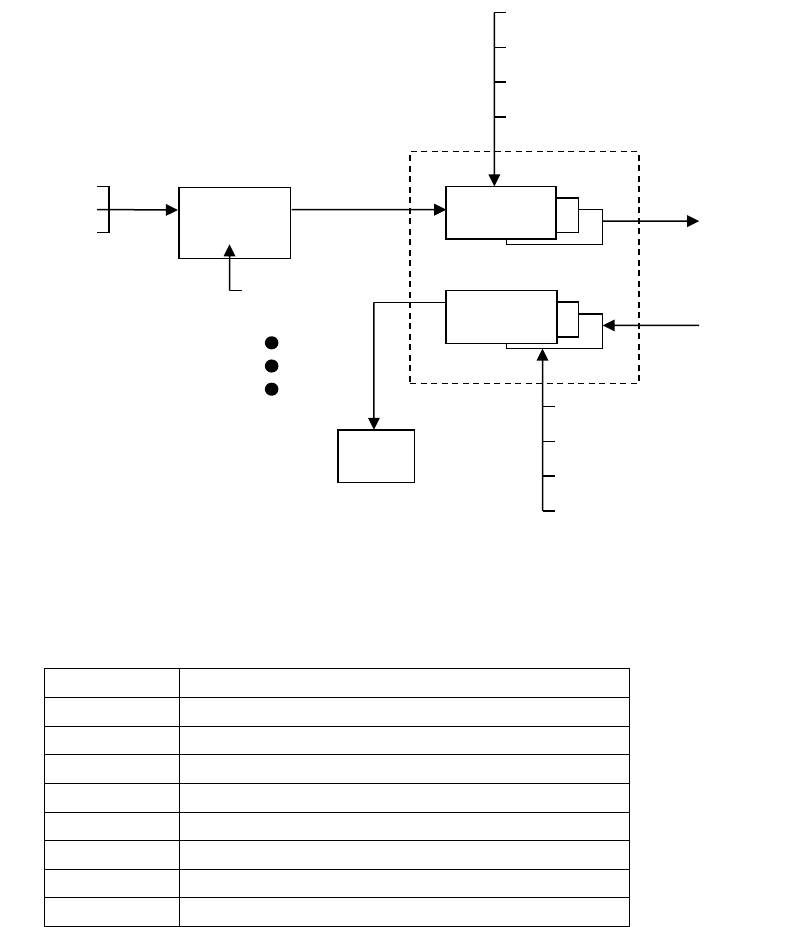
OPERATIONS
Page 63 MRC-565 Packet Data Radio Operations & Maintenance
Figure 7. Message Flow and Associated Commands
The following operations are explained in this section:
SECTION
OPERATIONS
5.3.1
Entering and Deleting Messages
5.3.2
Editing Messages
5.3.3
Sending Messages
5.3.4
Sending Commands
5.3.5
Sending Canned Messages
5.3.6
Receiving Messages
5.3.7
Examining Message Status
5.3.8
Examining and Revising Message Queues
5.4.1 Entering and Deleting Messages
All messages are composed and edited in the TEXT EDIT BUFFER. Messages may be 3,570
characters in length. When composing the message press [ENTER] at the end of each 80
character line.
There is a default destination programmed into the MRC-565 during the installation and
initialization of the unit when it is first brought on-line in the network. If a message is not given
a specific destination it will be sent to the default destination only.
To enter a message:
TX
QUEUE
PRINT
RX QUEUE
[SHOW]
[FLUSH]
[DEL]
[SMS]
[SHOW
]
[FLUSH]
[DEL]
[SMS]
TEXT EDIT
BUFFER
[MESSAGE]
[REMCMD]
[CANMSG]
EDIT COMMANDS
[ESC]
[DEL]
[ESC]
TO/FROM
NEIGHBORING
STATIONS
ACK
END-TO-END ACK

OPERATIONS
Page 64 MRC-565 Packet Data Radio Operations & Maintenance
1. Type MESSAGE. The operator terminal will respond with ENTER TEXT. The MRC-565
will now be in the compose and edit mode.
2. Enter a message up to 3,570 characters in length, pressing [ENTER] at the end of each 80
character line.
3. Press the [ESC] key. The message will now be transferred to a Tx queue and will be
automatically transmitted to the default destination at a priority level R.
The following message will be displayed, or printed, on the operator terminal:
hh:mm:ss Message No: name:ss,nnnn chars, nnn segments
hh:mm:ss ROUTING name :sss TXT sss/nn TO: name
If you wish to send a message to multiple destinations, and at a different priority level, type
MESSAGE, R, dest1, dest2, …dest n
where: “R” is any priority level from A to Z. A is the highest and Z is the lowest.
“Dest” is the numerical ID of the stations to which the message will be routed.
NOTE
If you also want to send the message to your default destination you must enter its station
numerical ID as one of the destination parameters (“dest1”, “dest2”, etc.) as specified
above.
Three other special editing functions may be used:
1. To Retransmit the Previously Entered Message
To retransmit a previously entered message simply depress the [ESC] key after the operator
terminal prints ENTER TEXT and before any other key is depressed. The previous message
entered into the TEXT EDIT BUFFER will then be sent to the destinations that are now
designated in the MESSAGE command.
2. To Revise the Previously Entered Message
To revise a previously entered message press [CTRL]T after the ENTER TEXT prompt to
revise a previously entered message or to recover from an aborted session. The previous
message will be displayed with the cursor placed at the end of the message. You may now
resume editing the message.
3. To Delete a Message
To delete a message after it has been placed in the Tx Queue, type

OPERATIONS
Page 65 MRC-565 Packet Data Radio Operations & Maintenance
DELMSG, ID: sss
where: ID is the numerical station ID
sss is the message serial number
The operator terminal will print the date and time, followed by MESSAGE DELETED.
5.4.2 Editing Messages
The following editing functions may be used from the keyboard while the message is in the
TEXT EDIT BUFFER.
KEY
FUNCTION
[DEL]
Deletes the last character entered.
[CTRL]R
Prints the current line of text on the next line down.
[CTRL]I
Performs a fixed tab function
\
Removes the current line from the edit buffer.
[ENTER]
Performs a carriage return and line feed.
[LF]
Performs a carriage return and line feed.
[CTRL]X
Removes the current line from the edit buffer and places the
cursor at the end of the previous line.
[CTRL]T
Prints the contents of the edit buffer & puts cursor at the end of
text.
[CTRL]D
Erases the entire contents of the edit buffer.
[CTRK]A
Aborts the edit mode and returns to the command mode.
A “+” indicates the command mode.
[ESC]
Leaves text edit mode and queues the message for transmission.
5.4.3 Sending Messages
Messages are automatically stored for transmission with the [ESC] key. Each message will be
placed in the Tx Queue in accordance with its assigned priority. Messages of equal priority are
placed in the Tx Queue in the order received from the TEXT EDIT BUFFER.
The following display will appear on the operator terminal as the MRC-565 stores and routes a
message:
hh:mm:ss Message No: name:ss,nnnn chars, nnn segments
hh:mm:ss ROUTING name :sss TXT sss/nn TO: name
Messages are transmitted in packets and are routed to their destination in a store and forward
manner, using the most efficient routing within the packet switched network. The originating
station will receive an acknowledgement (ACK) if the message has been received successfully
by the first routing station.

OPERATIONS
Page 66 MRC-565 Packet Data Radio Operations & Maintenance
mm/dd/yy hh:mm:ss TXTMSG ACK name:sss, xxxx CHARS FROM name
When the entire message has been delivered to its final destination an end-to-end
acknowledgement will be displayed on the operator terminal:
hh:mm:ss END-TO-END ACK OF name:sss FROM name
If the end-to-end ACK is not received within the specified time-to-live limit, the MRC-565 will
purge the message from the Tx Queue and display the following message:
hh:mm:ss MESSAGE TIME-TO-LIVE EXPIRED, MSG.NO:sss, DESTN: name
You must then reenter the message. Continued failure to successfully transmit a message
indicates that something may be wrong with the equipment or the link (e.g., excessive noise
interference).
5.4.4 Sending Remote Commands
Commands may be sent to any station within the network. The entry of a command is similar to
the MESSAGE command described in Section 4.3.1.
REMCMD, R, dest1, dest2, …destn
where: R = priority level
dest = numerical ID of destination station(s)
The operator is then prompted to enter the text of the command using the message editor. Once
the command is entered, press the [ESC] key to send the command. The operator terminal will
display:
A response will be received from the destination station(s) if it was successfully received.
5.4.5 Sending Canned Messages
The MRC-565 may be placed into a canned message mode for automatic transmission of a
repetitive message to an assigned neighboring station. In the canned message mode no more
hh:mm:ss Message No: name:sss, nnnn chars, nnn segments
Destination ID
Message Number (0-255)
Number of characters
Number of 14-character segments
OPERATIONS
Page 67 MRC-565 Packet Data Radio Operations & Maintenance
than 25 messages may be placed into the Tx Queue at one time. You may either send an edited
text message or a message that is generated from the alphabet.
To enter a canned message generated from the alphabet, enter:
CANMSG,id,msg length{,min.queue depth}{,total number of messages}
where “id” is the neighboring station ID, the message length is from 1 to 3000 characters and the
queue depth is from 1 to 25. The default queue depth is 5. Additional canned messages will be
automatically injected if the number of canned messages in the queue falls below the minimum
queue depth.
To enter an edited canned message, enter:
CANMSG,id
where “id” is the neighboring station’s ID. After composing your message press the [ESC] key.
The MRC-565 will automatically route up to 25 copies of the canned message to the destination
station.
Each canned message will be acknowledged by the selected neighboring station. No end-to-end
acknowledgement will be received.
If the TOTAL parameter was entered the canned message mode will stop when the desired
number of messages have been transmitted.
To manually terminate the mode, enter:
CANMSG OFF,id
Canned messages are normally not printed at the destination station. To print canned messages
as they are received, enter:
CANMSG MODE,PRINT
To turn off the print mode, enter:
CANMSG MODE,NO PRINT
5.4.6 Receiving Messages
When a new message is received it is announced by the following display:
hh:mm:ss RECEIVING name:sss TXT sss/nn FROM name ROUTED TO: name

OPERATIONS
Page 68 MRC-565 Packet Data Radio Operations & Maintenance
The MRC-565 then generates an ACK of the message packet and transmits the ACK to the
neighbor from whom the message was received:
hh:mm:ss TXTMSG ACK name:sss, nnnn CHARS FROM name
When the destination MRC-565 receives a complete message, it displays the following message:
hh:mm:ss MSG RECEIVED name:sss, xxxx CHARS
text………………………………
**end-of-message**
where “name:sss” is the message serial number.
Messages are deleted as they are displayed or printed unless they are being forwarded to further
destinations.
5.4.7 Examining Message Status
The status of all messages may be examined while they are still in the Tx Queue. (Note: once
an end-to-end acknowledgement is received for a message it is deleted from the queue).
To examine a message, enter:
SMS {,ID}
5.4.8 Examining and Revising Message Queues
There are two types of queues for transmitting and receiving messages:
QUEUE NAME
DESCRIPTION
TXQ
(Transmit
Queue)
This queue is used for transmitting all messages. There is a separate transmit
queue for each neighboring station in the network. For example, if you enter
a message for DEST1 That message is placed in DEST1’s transmit queue.
RXQ
(Receive
Queue)
This queue is used for all received messages. There is a separate receive
queue for each neighboring station in the network. For example, to examine
message statistics from NODE5, examine the receive queue from NODE5.
To examine the contents of either queue, type:
SHOW TXQ,ID or SHOW RXQ,ID
You must specify the queue by entering the station ID. For example, SHOW TXQ,006 prints
statistics for all messages being transmitted to station 006.
You can only examine the receive and transmit queues for neighbor stations in the network.
OPERATIONS
Page 69 MRC-565 Packet Data Radio Operations & Maintenance
To delete the contents of the transmit and receive queues, you must specify the exact queue by
entering a station name:
FLUSH TXQ,id or FLUSH RXQ,id
For each message deleted, the terminal prints:
Id:sss unlinked {and deleted}
The “and deleted” text appears only if the message is not present in another queue. When all
messages have been deleted, the terminal prints:
queue flushed
To delete a specific message, enter:
DEL MSG,id:sss
The terminal prints:
Message deleted
To delete all messages from all queues, enter:
FLUSH MSG
For each message deleted, the terminal prints:
Id:sss deleted
Entering the FLUSH MSG command deletes all messages in all queues for every node of the
network, including connectivity and end-to-end acknowledgment messages.
5.5 Sensor I/O Port
A limited data acquisition capability is built in to the MRC-565 for those applications when a full
data logger capability is not required. The following capability is provided:
4 optically isolated inputs for discrete ON/OFF functions
6 analog voltage inputs (0 to 5V)
2 solid state switches
In addition, +12VDC is supplied for sensor power and a +5V reference voltage for sensor
excitation is available.

OPERATIONS
Page 70 MRC-565 Packet Data Radio Operations & Maintenance
The Sensor port interface is a 25-pin male D connector. The connector pin outs and their
respective functions are shown below.
The analog voltages are routed to a 12-bit analog-to-digital converter (ADC) which provides a
resolution of +/-.1% and an accuracy over temperature of 1%.
SIGNAL PORT
Pin
Signal
1
Optocoupled input #1 positive
(500 ohm resistor)
2
SDI-12 Data
3
Optocoupled input #2 positive
(500 ohm resistor)
4
Optocoupled input #1,2,3,&4 return
5
Optocoupled input #3 positive
(500 ohm resistor)
6
Det RF Channel 3
7
Optocoupled input #4 positive
(500 ohm resistor)
8
Det RF Channel 2
9
Ground
10
SS Relay Out #1 - .5 Amp Rating
11
SS Relay Out #1 +
12
Signal Presence SP
13
SS Relay Out #2 - .5 Amp Rating
14
SS Relay Out #2 +
15
TX Key
16
+5V Reference (10 ma max) +/- 2%
17
Analog Input #1 ( 0 to 5 V)
18
Analog Input #2 ( 0 to 5 V)
19
Analog Input #3 ( 0 to 5 V)
20
Analog Input #4 ( 0 to 5 V)
21
Analog Input #5 ( 0 to 5 V)
22
Analog Input #6 ( 0 to 5 V)
23
+12V Switched (.5 A Max)
24
+12V (0.5A Max)
25
Detected RF Channel 1
A 25-pin terminal block is a convenient means for interfacing to the various sensors and control
points.
5.6 Data Loggers Interface

OPERATIONS
Page 71 MRC-565 Packet Data Radio Operations & Maintenance
Any data logger that MRC supports and has an RS-232 interface may be connected to any one of
the 3 ports on the MRC-565. Normally, the Data or AUX Port is used. You may connect to
either port using a 9-pin “D” type connector:
PIN
FUNCTION
2
TX Data
3
RX Data
5
Ground
Three commands are required to configure the Data Port for proper operation with the particular
data logger being used:
ASSIGN,DTA,OFF [ENTER]
ASSIGN, DTA, 1, type [ENTER]
The first command clears any previous assignments that still may be in effect for the DTA Port.
The second command assigns a specific type of data logger and protocol to the DTA Port. The
specific type of data loggers that MRC supports may be obtained from MRC or your System
Administrator.
The following section explains the interface of Campbell Scientific Data LoggerS to MRC-565.
5.7 CR10X Data Logger
The MRC-565 RF Modem can be used with the Campbell Scientific CR10X data logger to
transmit data from a remote site to a destination in a Meteor Burst (MB) or Line-Of-Sight (LOS)
network. Because of the unique timing of a MB system, the MRC-565 does not provide a real-
time connection between a CR10X and a PC running a data collection program as a pair of
dedicated phone modems would. The connection is a packet store-and-forward type instead.
The design approach used was not to add the MRC-565 to the list of modems supported by the
CR10X, but to add the CR10X to the list of data loggers supported by the MRC-565. Each
CR10X data-array recorded in the final storage is treated as a data logger packet by the MRC-
565. Packets are acquired by the MRC-565 from the CR10X, and delivered through the MB
network to another MRC-565 or master station. The packets are then “printed” on one of the RS-
232 ports at the destination unit in a format that is compatible with all the other supported data
loggers.
In this type of system, the central data system does not “poll” each remote for its data. Instead,
each remote MRC-565 gets the data from the locally attached CR10X using an internal data
acquisition schedule and CR10X driver software module, then routes it to a particular
destination. The MRC-565 driver module uses the CR10X telecommunications commands to
read the data from the final storage. It is then the responsibility of the central data system to store
and process the data as it arrives from each remote site.
OPERATIONS
Page 72 MRC-565 Packet Data Radio Operations & Maintenance
Because of the flexibility of both the CR10X and the MRC-565, several parameters must be
setup to define the operation of the data acquisition process used to get data from the CR10X to
the MRC-565. The following sections show the command structure as it relates to the CR10X
driver, and then discusses each command in detail.
5.7.1 CR10X Commands
The following tree diagram shows the commands used to set up and configure the CR10X data
Logger drivers in the MRC-565 RF Modem.
An example is: CR10X,ACQMODE,ALL.

OPERATIONS
Page 73 MRC-565 Packet Data Radio Operations & Maintenance
CR10X Display CR10X configuration parameters
,ACQMODE,ALL Get all reports since previous scan
,CURRENT Get only the current (last) data group
,LAST,N Get only the last ‘N’ data groups (backsup ‘N’ data
groups from the last one)
,SETPTR,DATE,TIME Manual set up of last data pointer in
the MRC-565
,INTERVAL,N Scan interval in seconds
,OFF Scan only when UPDT command is entered
,ORDER,FIFO Get final storage data in FIFO order
,LIFO (not avail) Get final storage data in LIFO order
,GROUP,MRC-565A Let MRC-565 assign group numbers
,CR10X Get Group Number from 1st stored sensor
,TIME,MRC-565A Use MRC-565 internal Time
,CR10X Get time from 2nd and 3rd sensor
,MAXQ,NNN Set maximum number of reports to queue
for each scan of the CR10X
,SCALE,CR10X Scale sensors in cr10X Hex units
,INT (or MRC-565A) Scale sensors in integer Hex units
,REGISTER,N Read internal storage register ‘N’
N,DDD Set internal storage register ‘N’ to ‘DDD’
,STAT Read and display CR10X internal pointers
and error statistics.
,RESET Reset CR10X internal error statistics.
,SECURITY,1111,2222,3333 Enter CR10X Internal Security Codes
,SIGNATURE Read and Display Current CR10X programs
Signature.
,MODEM ENABLE Enable/Disable use of ME/Ring control
5.7.2 Parameter Default Values
Default values are set up to support systems already deployed in the field. These are defined to
allow only the last single data group to be read each time the UPDT command is entered or
scheduled in the MRC-565. The time tag will use internal MRC-565 date and time, it is assumed
the day and time are not stored in the CR10X data arrays, scaling will be in CR10X Hex format,
transmission in FIFO order, group assignment by the MRC-565 and the maximum queue depth
OPERATIONS
Page 74 MRC-565 Packet Data Radio Operations & Maintenance
will be 200. The use of MODEM ENABLE is normally off and the RING line is tied high to
keep the CR10X in an active state.
The current values are viewed by entering CR10X<Enter> as shown in the following example.
+cr10x 04/08/14 10:43:12
ACQMODE = ALL
INTERVAL = OFF
ORDER = FIFO
GROUP = CR10X
TIME = CR10X
MAXQ = 3
SCALE = CR10X
MODEM ENABLE = OFF
5.7.3 Acquire Mode
There are three modes used by the MRC-565 for controlling data acquisition from the CR10X.
These are "ALL", "CURRENT", and "LAST,N".
The CR10X,ACQMODE,ALL mode will read all the data recorded in the Final Storage area
starting from the last location read by the MRC-565. This is useful where all the data for each
site is important, not just the most-recent data. This mode lets the CR10X gather data for a while
then the MRC-565 can acquire all that was stored later. For example, you might want the CR10x
to store data every hour, but have the MRC-565 acquire and transmit all of it at midnight. For
each scan, the MRC-565 will read as many data reports as it can, limited by the
CR10X,MAXQ,NN setting, and the amount of available memory. These two limits are
discussed below in the memory management paragraph.
The CR10X,ACQMODE,CURRENT mode will only get the very last single data group stored
in the Final Storage area with each scan. It assumes there is only one group for each data
interval. This is compatible with systems already installed in the field.
The CR10X,ACQMODE,LAST,N mode will read the last "n" data groups each time a scan is
scheduled. The value of "n" is set to the number of groups in each reporting interval. This mode
is useful when you want to be able to change the reporting interval remotely, and the cr10X
program cannot be modified. For example, you can setup the CR10X program to record data
every minute, but have the MRC-565 acquire the most recent data every hour. You can then
change the MRC-565 acquisition scan timing to any interval from one minute to 24 hours
without modifying the CR10X program.
OPERATIONS
Page 75 MRC-565 Packet Data Radio Operations & Maintenance
5.7.4 Data Retrieval Pointer Initialization
The CR10X,SETPTR,XXXX command is used to control where the next data will be read from
the CR10X Final Storage. The MRC-565 maintains an internal pointer for reading data. This
pointer is accessed each time the MRC-565 requests data from the CR10X. The CR10X records
data in a “circular ring buffer” mode and will reuse memory locations as long as it remains
operational. If required, as in the case where older data was lost, when data must be re-read from
the CR10X and retransmitted by the MRC-565, the internal MRC-565 data pointer can be
modified to point to the start of the required data. In addition, when an MRC-565 is replaced, but
the CR10X still has data, it will be necessary to set the pointer in the new MRC-565 to the last
known location of the old MRC-565.
There are two variations of this command. The form allows the operator to set the pointer to a
numerical location. This may be known, and can be read using the STAT command shown
below. The CR10X,SETPTR,DATE,TIME form will search through the CR10X Final Storage
memory and set the pointer to the first data array that is equal to or greater than the given date
and time. The search uses a binary algorithm, and will take a few seconds to locate the desired
data point. This search mode can only be used if the CR10X has recorded the group number, date
and time in the first three locations of each data array as discussed below in the Group ID
Assignment and Time of Day paragraphs.
5.7.5 Update Interval
The update CR10X,INTERVAL,N sets up the number of seconds between scans of the data
from the CR10X. If N is set to OFF, then the MRC-565 internal SCHED command can be used
to schedule UPDT,TX commands at any particular time, or interval. When set to a number from
1 to 32767 seconds, an internal timer triggers an UPDT,TX type of action at the desired interval.
The interval is synchronized with time-of-day so that an interval of 10 seconds (for example)
falls on 0, 10, 20, 30, 40, 50 seconds of each minute. The interval can be set more often than data
is recorded in the Final Storage, and is there is no new data since the last scan, nothing will get
queued.
5.7.6 Transmission Order
The order of transmission is currently limited to FIFO, but provision has been made for a later
version to support LIFO.
5.7.7 Group ID Assignment
The group ID can be assigned in the CR10X data arrays, or can be assigned by the MRC-565.
Each group can contain from 1 to 16 sensor data values. The MRC-565 mode will assign group
number 2 to each group report by default. This is for compatibility with older systems deployed
in the field.
OPERATIONS
Page 76 MRC-565 Packet Data Radio Operations & Maintenance
The CR10X mode uses the group ID assigned in the CR10X by using the P80,p1,p2 instruction
in the CR10X DLD File, where the 1st parameter selects Final Storage area 1, and the 2nd
parameter defines the group (array ID) number. These can be assigned from 0 to 15.
5.7.8 Time of Day
To send the MRC-565 time to the CR10X, enter (or schedule) a UPDT,TIME command. This
will not be done when a time probe is received from the master station, as it might cause a skip
in the data acquisition cycle. It should be scheduled to happen at a convenient time of day or
interval using the MRC-565 SCHED command such that data will not be lost if the time
advances or retards across an acquisition interval. If the time update is more than +/- two minutes
from the current CR10X time, then a time resync message will be transmitted to the default
destination.
5.7.9 Time Tagging
The time tag assigned to each group report can be taken from the MRC-565 internal date and
time as the data is read, or it can use a CR10X internal time stored in the data array.
To use the CR10x internal time, the date and time in the CR10X DLD File must be set up in
each group as the first two sensor values of the group using the code "110" in the P77
instruction. This records the Julian day as the first sensor, and the Hour/Minute as the second
sensor. The maximum number of sensors would then be 18, and actual data would be in sensors
3-18 for 16 values. The MRC-565 will use sensor slots 1-16 for this data rather than 3-18. The
time tag is placed in the data report header.
If the MRC-565 time is used, actual sensor data can be recorded in sensors 1-16. If the data
array has the time in each record, but you use the MRC-565 time stamp, then the 1st two sensors
which actually contain the CR10X date and time will be treated as the 1st two sensor values.
There is no option to skip the 1st two data array values in this case, except to use the CR10X
time tag mode.
5.7.10 Memory Management
Each time the MRC-565 reads data from the CR10X, it saves the last data pointer accessed in the
CR10X’s Final Storage RAM. This is used at the next scheduled update interval to get the next
data values without missing anything.
If there is no new data recorded in the Final Storage area when the MRC-565 scans, then nothing
is transmitted. The MRC-565 will try again at the next interval. The interval can be set from 1 to
32767 seconds. A good typical value to use is 60 seconds.
OPERATIONS
Page 77 MRC-565 Packet Data Radio Operations & Maintenance
The MRC-565 limits the amount of data read from the CR10X to prevent overflowing its’
transmit memory queue. Each time a group is read, the available memory is checked, and if it
goes below 600 Queue blocks, then the MRC-565 will stop reading data from the CR10X until
the next scan interval. As data is transmitted, memory will get freed up for the next interval.
The CR10X,MAXQ,N setting is used to limit the number of group reports created with each
scan. For example, if MAXQ is set to 20, each scan will read, at most, 20 group reports. 20 more
will be read at the next interval, etc. There is no provision for limiting the length of the transmit
queue as in the MRC-550 data acquisition unit. In effect, limiting the transmit queue length can
be accomplished by setting the SNP,TTL,NN time to purge reports older than the given number
of minutes.
5.7.11 Data Scaling
Two data formats are supported, and must agree with the setup of the internal CR10x Program.
Only the low-precision format is currently supported.
The CR10X,SCALE,CR10X format will use the Campbell Scientific floating point format and
assumes the sensors are calibrated in engineering units within the CR10X.
The CR10X,SCALE,INT format assumes each sensor is calibrated in integer mV, and formats
the data in 2's complement integer Hexadecimal format by truncating the fractional part of the
floating point number. Example: CR10X outputs 103.7, MRC-565 truncates it to 103, then
converts it to hex 0067. The value -103.7 will be converted to hex FF99. The cr10X maximum
low-precision values are 13 bits where +6999 is converted to hex 1B57 and -6999 is converted to
hex E4A9. The MRC-565 uses 16 bits for each sensor data value, but the MRC-550B/C (and
some customers) is limited to 12 bits of significance.
5.7.12 Modem Enable
By default, the use of the MODEM ENABLE line is turned OFF and the RING line is tied high
to keep the CR10X awake. For applications that require very low power, the CR10X can go to
sleep between operations, and must be woken up to communicate with it. This mode is enabled
in the MRC-565 by the command: CR10X,MODEM ENABLE,ON. When the MRC-565 wants
to communicate with the CR10X, it raises the RING line, and waits for the CR10X to raise the
ME line. The ME line must be tied to the RTS line of the MRC-565. Once the ME line is high,
the MRC-565 lowers the RING line and begins its command sequences. When the last
command is completed, the MRC-565 sends an "E<cr>" command to the CR10X to put it back
to sleep.
OPERATIONS
Page 78 MRC-565 Packet Data Radio Operations & Maintenance
5.7.13 Setting/Reading CR10X Internal Registers
The CR10X has internal registers that are used to hold data while it is being manipulated prior to
being output to final storage memory. The MRC-565 can read these registers using local or
remote commands and transmit the contents back to the originator of the remote command. In
addition the contents of the registers can be changed via remote command. This capability allows
the CR10X internal program to access a register value as a parameter that can be changed
remotely. Some uses might include controlling switches, motors, software options, final storage
update rate, input scan rate, etc.
To read a register use the command CR10X,REGISTER,N where "n" is the register number.
The result will be displayed as follows:
+cr10x,register,1 01/08/99 10:42:37
[+12.355 ]
The current value in the register is shown within the square brackets.
To change a register use the command CR10X,REGISTER,N,XXXX where "n" is the register
number and "XXXX" is the new contents in decimal or "0xHHHH" is the new contents in
hexadecimal. The following example shows the old value in square brackets followed by the new
value.
+cr10x,register,1,10.4 01/08/99 10:42:49
[+12.355 ] +10.400
Reading CR10X Internal Pointers and Error Statistics:
The CR10X,STAT command will read and display the CR10X internal pointers and error
counters. The following example shows the response format:
+cr10x,stat 01/08/99 10:39:44
R10185 F62262 V3 A1 L10151 E00 02 00 M0256 B+3.1117 C2858
MRC-565A DPTR:08219 008 09:42, CR10X Start:007 04:09 End:008 10:39
The first line of the response is the “A” command response from the CR10X. It shows “R”xxxx
the current data pointer, “F”xxxx the number of filled memory locations, “A”x the storage area
number, “L”xxxx the last modem pointer, “E”xx xx xx error statistics, “M”xxxx memory size,
and “B”xxxx internal battery voltage. The “C”xxxx is a checksum value and not otherwise
useful.
The second line is the MRC-565 current data pointer value, the Julian day and time (hr:mn) of
the report at that location, the day and time of the oldest and newest report in the CR10X Final
Storage memory. The values on this line depend on the format of the data arrays having the
Julian day and time in the first two sensor locations as discussed in the “Time Tagging”
paragraph above.
OPERATIONS
Page 79 MRC-565 Packet Data Radio Operations & Maintenance
Resetting CR10X Internal Error Statistics:
The CR10X,RESET command will zero the CR10X internal error counters.
+cr10x,reset 01/08/99 10:41:48
R10253 F62262 V3 A1 L8219 E00 00 00 M0256 B+3.1117 C3042
MRC-565A DPTR:08213 008 09:42, CR10X Start:007 04:11 End:008 10:41
This format is the same as for the STAT command shown above. Note that the error counter has
been zeroed.
5.7.14 Entering CR10X Security Codes
The CR10X uses security codes that are set up within the source code of the stored program.
When these are included in the source code, and their values are non-zero, then access will be
inhibited as described in section 1.7 of the CR10X Operators Manual. Of the 3 codes used, the
MRC-565 needs code 1 and 3. Code 1 inhibits downloading and uploading operations, while
code 3 inhibits all telecommunications operations except those required to allow setting up a
connection to the CR10X. To enter the codes, use the command
CR10X,SECURITY,XXXX,YYYY,ZZZZ
Where xxxx is code 1, yyyy is code 2 and zzzz is code 3.
5.7.15 Downloading a CR10X .DLD Program
A new or revised CR10X internal program can be transmitted to an MRC-565 which will then
download it to the CR10X and tell the CR10X to compile and run it. The program source, in
".dld" format must be copied into a message (or multiple messages if longer than 3500 bytes)
that starts with "$CR10X,DOWNLOAD," as the first 16 characters is the message fragment.
Note: the last character must be a comma following the message fragment identifiers. Do not
forget to use caps on all letters and to include the comma after DOWNLOAD. You should edit
the .DLD files to remove all unnecessary information in order to reduce the size of the message
as much as possible. Any program lines preceded with a “;” are comment lines and can usually
be eliminated.
Following is the procedure to download a “.dld” file into the CR10X using XTERMW.
You can use Base/Master Station to send this file to the Remote Station , or you can connect to
the Operator Port (MNT) directly to the Remote Station.
1. Modify the “.dld” file to start with “ $CR10X,DOWNLOAD,”
2. Save the “.dld” file as ”.msg” file, which starts with "$CR10X,DOWNLOAD," .Go
3. “Send” and to “Message File…”
4. Enter the destination ID, Browse to the desired “.msg” file and click Open
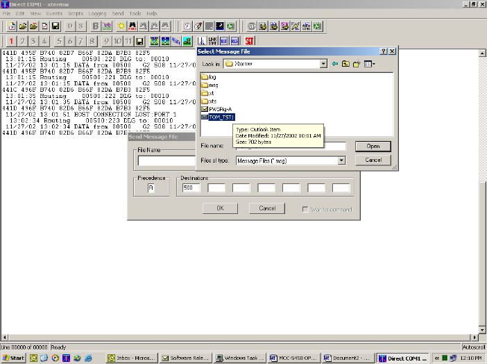
OPERATIONS
Page 80 MRC-565 Packet Data Radio Operations & Maintenance
The maximum message file length including the 16 character header must be no greater than
3500 characters. If the file length is larger than this, it can be reduced in length by editing it to
remove comment lines and blank lines, or use XTERM DOS Version for larger files. (XTERM
DOS can be obtained MRC upon request.) When an MRC-565 with a device driver assigned to
the CR10X receives the message in this format it will be sent to the CR10X, compiled, and begin
executing. A status message will be returned to the unit that originated the download message
indicating whether the compilation was successful.
If the program is different than the previous program, the memory in the final storage area will
be deleted, otherwise it will be left untouched. Refer to the Campbell Scientific documentation
for details on exactly when the data is deleted or not.
5.7.16 Replacing an MRC-565 to an Operational CR10X
When an MRC-565 is connected to a CR10X that has been previously collecting data, the data
pointers in the MRC-565 must be set to the current data point in the CR10X. If this is not done,
the MRC-565 pointers will begin retrieving data from location 1 in the data logger. If this is not
done then the data retrieved will either be all the data collected since installation or the data at
the time the cR10X memory last filled and rolled back to re-use memory from location 1.
OPERATIONS
Page 81 MRC-565 Packet Data Radio Operations & Maintenance
1. Before connecting the MRC-565 data cable to the CR10X, enter the
CR10X,INTERVAL,OFF and CR10X,MAXQ,1 commands to disable the automatic data
acquisition.
2. Connect the MRC-565 data cable to the CR10X, then enter the CR10X,STAT command to
read the current pointer from the CR10X.
+CR10X,STAT 03/27/04 14:11:48
R+2113. F+2112. V5 A1 L+2113. E00 00 32 M0256 B+3.1027 C2967
MRC-565A DPTR:1563 331 12:26, CR10X Start:331 10:04 End:331
13:15
This report will show the MRC-565 pointer (DPTR:) and the current and maximum CR10X
pointer. It also shows the start and end dates for the data set in the CR10X. Note that it does
not contain the year when the data was acquired. This is why we position the pointers using
the actual pointers, rather than the data report date.
3. Enter the CR10X,SETPTR,xxxxxx command to set the pointer in the MRC-565 and the
CR10X to the desired point Enter the CR10X,STAT command again to verify the pointers.
4. Return the Interval and Maxq settings to the desired values to begin automatic reporting, e.g.
CR10X,INTERVAL,60 and CR10X,MAXQ,200.
5. If it is necessary to recover data from the CR10X and automatically transmit it to the Host,
follow the instructions in the following section.
5.7.17 Replaying Data from a CR10X
Data can be replayed from a CR10X by determining where the current data pointer is in the
CR10X, calculating the approximate location of the start of the data to be replayed and then
setting the pointer to that location. (Note: The MRC-565 and CR10X have commands for setting
the pointer by date and time, but this only works if all the data in the CR10X is for the current
year. If the CR10X cannot locate the proper data, you may lose control of the CR10X, Then, do
NOT use these commands.)
To locate the position of the current data pointer, determine which master station the remote is
reporting to and send a CR10X,STAT command to the remote. The remote command response
will contain the current pointers (“R”) (Command responses will not be immediately received in
a meteor burst system):
11/27/02 14:36:17 Command response received from 00500
#CR10X,STAT 11/27/02 14:36:10
# R+2377. F+2376. V5 A1 L+2377. E00 00 32 M0256 B+3.1027 C3003
# MRC-565A DPTR:2377 331 13:39, CR10X Start:331 10:04 End:331 13:39

OPERATIONS
Page 82 MRC-565 Packet Data Radio Operations & Maintenance
To now replay the data, determine the current pointer and note the date and time of the pointer
reading. Each site uses about 50 words of CR10X final storage per hour, therefore determine
how many hours you want to move the pointer back. Multiply by 50 and subtract the result from
the current point. Send the new pointer to the remote with the CR10X,SETPTR,nnnnnn
command. The remote will send back the new pointer setting:
11/27/02 14:42:41 Command response received from 00500
#cr10x,setptr,2300 A1 L+2300 C0884
# 11/27/02 14:42:33 Completed
# 11/27/02 14:42:31
# R+292750. F+2453. V5 A1 L+2454. E00 00 32 M0256 B+3.1027 C2991
# MRC-565A DPTR:291200 331 13:33, CR10X Start:331 10:04 End:331 13:46
In this example, the pointer was set back from 292750 to 291200- about 31 hours.
NOTE 1
2043 will report four groups hourly and will use about 70 words per hour.
NOTE 2
If the pointer calculation goes negative the pointer has wrapped around. Add the
maximum pointer value to the negative pointer (“F”?) to determine the proper value.
5.8 CR1000 Data Logger
The MRC-565 Packet Data Radio (hereafter called the radio) can be used with the Campbell
Scientific CR1000 data logger to transmit data from a remote site to a destination in a Meteor
Burst (MB) or Line-Of-Sight (LOS) network. Because of the unique timing of a MB system, the
radios do not provide a real-time connection between a CR1000 and a PC running a data
collection program as a pair of dedicated phone modems would. The connection is a packet
store-and-forward type instead.
Each CR1000 table data array recorded in the final storage is treated as a data logger packet by
the radio. Packets are acquired by the radio from the CR1000, and delivered through the MB
network to another relay radio or master station. The packets are then "printed" on one of the RS-
232 ports, or Ethernet port at the destination unit in a format that is compatible with all the other
supported data loggers.
In this type of system, the central data system does not "poll" each remote for its data. Instead,
each remote radio gets the data from the locally attached CR1000 using an internal data
acquisition schedule and CR1000 driver software module, then routes it to a particular
destination. The radio’s driver module uses the Campbell Scientific PakBus Network Layer and
SerPkt serial port protocols to read the data from the CR1000 Tables. Data is reformatted into the
SDATA and MBNET standard format for transmission. It is the responsibility of the central data
system to store and process the data as it arrives from each remote site.
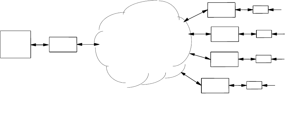
OPERATIONS
Page 83 MRC-565 Packet Data Radio Operations & Maintenance
CR1000
DATA
SENSORS
CR1000
MCC-545
RF MODEM
DATA
SENSORS
CR1000
MCC-545
RF MODEM
DATA
SENSORS
CR1000
MCC-545A
RF MODEM
DATA
SENSORS
RF NETWORK
MCC-545
RF MODEM
CENTRAL
DATA
SYSTEM
MCC-545
RF MODEM
TYPICAL DATA ACQUISITION SYSTEM
Figure 8. Typical Data Acquisition System
Because of the flexibility of both the CR1000 and the radio, several parameters must be setup to
define the operation of the data acquisition process used to get data from the CR1000 to the radio
RAM data transmit queues. The following sections show the configuration and control command
structure as it relates to the CR1000 driver, and then discusses each command in detail.
The MRC-565 interface to the CR1000 using Campbell Scientific PAKBUS protocol. A
PAKBUS ID must be assigned to the MRC-565 before communications can occur. You can
assign the ID with the following command:
PAKBUS,ID,nnn
Where nnn is the ID. You can use any ID from 1-4095, but it must be different than the ID used
for the CR1000. The CR1000 is typically programmed with ID = 1. To verify the MRC-565 ID
enter the following command:
PAKBUS
The following data is returned:
PAKBUS 05/07/14 14:46:28
ID :nnn
Interval : 60
INF : 15
MyHop : 4
MyLstVer : 0
PakID IsRt Hops Port LinkState Sessions Age Modem IsCtl Isand BInt

OPERATIONS
Page 84 MRC-565 Packet Data Radio Operations & Maintenance
5.8.1 CR1000 Driver Configuration Command Summary:
The following list shows the commands used to set up and configure the CR1000 data Logger
drivers in the Packet Data Radios. Each command is detailed in the pages following.
CR1000 Display CR1000 configuration parameters
CR1000,ACQMODE,ALL Get all reports since previous scan
CR1000,ACQMODE,CURRENT Get only the current (last) data group
CR1000,ACQMODE,LAST,N Get only the last 'N' data groups (backs up
‘N’ data groups from the last one)
CR1000,SETPTR, Manual set up of last data pointer(s) in
CR1000,SETPTR,DATE,TIME the RADIO. Set all data pointers to this
Date and Time. DATE={mm/dd/yy} TIME={hh:mm}.
CR1000,SETPTR,RECORD,GROUP Set GROUP data pointer to this RECORD number.
GROUP = integer 1-16, RECORD = integer
0-4,294,967,295. Note: Use CR1000,STAT to
determine valid groups and group record pointers.
CR1000,INT,N Scan interval in seconds
CR1000,INT,OFF Scan only when UPDT command is entered
CR1000,ORDER,FIFO Get final storage data in FIFO order
CR1000,ORDER,LIFO (not avail)Get final storage data in LIFO order
CR1000,GROUP,545 Not implemented. Group numbers come from
CR1000,GROUP,CR1000 CR1000 only.
CR1000,TIME,545 Use radios internal Time
CR1000,TIME,CR1000 Get time from CR1000 BMP-5 packet.
CR1000,MAXQ,NNN Set maximum number of reports to queue
for each GROUP in the CR1000.
CR1000,SCALE,CR1000 Not available. Scale sensors in CR1000 HEX
CR1000,SCALE,INT only.
CR1000,STAT Read and display CR1000 beginning, current and
end group pointers and time stamps.
CR1000,SECURITY,1111,2222,3333 Enter CR1000 Internal Security Codes (Not
Currently implemented)
CR1000,MODEM ENABLE Enable/Disable use of RI/ME control
CR1000,TSWATH,BEGIN,END,{TX} Hole collection using date and time. This command
Will set all group record pointers to the begin
time Where: BEGIN ={mm/dd/yy,hh:mm} and
END = {mm/dd/yy,hh:mm}. The optional TX, if
I ncluded, will transmit SDATA reports. Note: Use
CR1000,STAT to determine valid date and time
stamps.
CR1000,TABLEDEF Show current tables and fields that are
programmed into the CR1000.
CR1000,GETTIME Display current CR1000 date and time.
OPERATIONS
Page 85 MRC-565 Packet Data Radio Operations & Maintenance
CR1000,STATUS,ALL Displays all Status fields in list form.
CR1000,STATUS,FIELD NAME Display CR1000 Status Table fields and values.
Where: FIELD NAME is a required parameter.
FIELD NAME, if included, will display value of the
named CR1000 Status Table field. Note: FIELD NAME
is an ASCII label of a variable in the table.
CR1000,PUBLIC,ALL Displays all Public fields in list form.
CR1000,PUBLIC,FIELD NAME,{xxx} Display CR1000 Public Table fields and values.
Where: FIELD NAME is a required parameter.
FIELD NAME, if included, will display value of the
named CR1000 Status Table field. Note: FIELD NAME
is an ASCII label of a variable in the table.
Xxx is an optional parameter. If it is used it will
Replace the original value of that public field.
If it is not used then the current value of the
Field will be displayed.
Default Values
Default values are set up to support systems already deployed in the field. These are defined to
collect all data groups to be read each time the UPDT command is entered or scheduled in the
radio. The time tag will use internal CR1000 date and time CR1000 table data arrays, scaling
will be in CR1000 Hex format, transmission in FIFO order, group assignment by the CR1000
and the maximum queue depth will be 20. If connected to the CSI port, MODEM ENABLE
must be "ON" for communication to take place directly between the radio and CR1000. If the
RS-232 port is used then set CR1000, MODEM ENABLE, OFF.
The current values are viewed by entering CR1000<Enter> as shown in the following example.
+cr1000 09/26/05 09:21:28
ACQMODE = ALL
INTERVAL = OFF
ORDER = FIFO
GROUP = CR1000
TIME = CR1000
MAXQ = 20
SCALE = CR1000
MODEM ENABLE = OFF
Table Name Fields Nsens NumRecs LastRec# FirstRec# Interval Signature
Status 98 1208 1 0 0 0 3292
Group1 1 16 3280 0 0 120 D10D
Group2 1 16 3280 0 0 120 D4C5
Group3 1 16 3280 0 0 120 E83A
Group4 1 16 3280 0 0 120 EDCD
Group5 1 16 3280 0 0 120 5B49
Group6 1 16 3280 0 0 120 B453
Group7 1 16 3280 0 0 120 D629
Group8 1 16 3280 0 0 120 F9DF
Group9 1 16 3280 0 0 120 3332
Group10 1 16 3280 0 0 120 A325
Group11 1 16 3280 0 0 120 FE23
Group12 1 16 3280 0 0 120 B14B
Group13 1 16 3280 0 0 120 833E
Group14 1 16 3280 0 0 120 2896
Group15 1 16 3280 0 0 120 6D25
Group16 1 16 3280 0 0 120 99E4
Public 3 3 1 0 0 0 D9AE
OPERATIONS
Page 86 MRC-565 Packet Data Radio Operations & Maintenance
+
5.8.2 Acquire Mode:
There are three modes used by the radios for controlling data acquisition from the CR1000.
These are "ALL", "CURRENT", and "LAST,N".
The CR1000,ACQMODE,ALL mode will read all the data records in each Table, starting from
the last location pointers set into the radio. This is useful where all the data for each site must be
transmitted, not just the most-recent data. This mode lets the CR1000 gather data independently
and lets the radio acquire and transmit the data as the MB RF Link permits. For example, the
user might want the CR1000 to store data every hour, but have the radio acquire and transmit all
of it at midnight, or have the radio acquire and transmit data as soon as possible. For each scan of
final storage the radio will read as many data reports from each Table in the CR1000 as it can.
The command CR1000, MAXQ, NN sets the maximum number of data reports to be acquired
per scan. These limits are discussed below in the memory management paragraph.
The CR1000,ACQMODE,CURRENT mode will acquire and transmit only the last or most
recent data record in each Table for every scan of the CR1000’s final storage.
The CR1000,ACQMODE,LAST,N mode will read the last "n" data records from each Table
each scan of the CR1000’s final storage. This mode is useful when you want to be able to change
the reporting interval remotely, and the CR1000 program cannot be modified. For example, you
can setup the CR1000 program to record data every minute, but have the radio acquire the most
recent data every hour. You can then change the radios acquisition scan timing to any interval
from one minute to 24 hours without modifying the CR1000 program.
5.8.3 Data Retrieval Pointer Initialization
The normal data collection method is to set the pointers to the last or most-recent data record,
then let the radio collect and transmit data whenever new data has been recorded into the
CR1000 final storage. The pointers will also be set to the most recent data report if the radio
resets. Power failures and subsequent recovery will leave the pointers where they were at the
time of the failure and continue from that point in a 545B, but will be lost in a 565 radio.
The radio maintains an internal pointer for accessing each data Table in the CR1000. These
pointers are accessed each time the radio requests data from the CR1000. The CR1000 records
each data Table in a “circular ring buffer” and will reuse memory locations when the Table gets
full. The size of each Table can be displayed using the CR1000 command. The size value uses
the field name MAXRECORDS. It should be noted that the pointers increment from 0 -
4,294,967,294 but the “circular ring buffer” MAXRECORDS limit is a much smaller number.
Any time stamps prior to the oldest, or beyond the newest of the actual records stored will not be
valid.
The CR1000, STAT will display the start, current, end and time stamps pointers for each Table.
OPERATIONS
Page 87 MRC-565 Packet Data Radio Operations & Maintenance
+cr1000,stat 02/21/14 15:46:33 Waiting...
---------First--------- ---------Current------- ----------Last---------
Grp Date Time Record Date Time Record Date Time Record
=== ======== ===== ======== ======== ===== ======== ======== ===== ========
01 02/21/14 13:00 00000000 02/21/14 15:00 00000003 02/21/14 15:00 00000002
02 02/21/14 13:00 00000000 02/21/14 15:00 00000003 02/21/14 15:00 00000002
03 02/21/14 13:00 00000000 02/21/14 15:00 00000003 02/21/14 15:00 00000002
04 02/21/14 13:00 00000000 02/21/14 15:00 00000003 02/21/14 15:00 00000002
05 01/01/90 00:00 00000000 01/01/90 00:00 00000000 01/01/90 00:00 00000000
The CR1000, SETPTR, DATE, TIME command is used to control where the next data will be
read from the CR1000 Final Storage using a date and time stamp value. The DATE and TIME
parameters must be within the start and end pointers time stamp boundaries. For instance,
assume the Table data record pointer is pointing at the last record entry which happens to be
3000. The user can not, in this example, set the pointer to a number larger than 3000, or cannot
set the date/time values to a time beyond the time stamp of the last record. The CR1000,
SETPTR, DATE, TIME command will search through the CR1000 Final Storage memory and
set the pointer to the first data array that is equal to or greater than the given date and time. The
search will take a few seconds to locate the desired data point.
The CR1000, SETPTR, XXXX, G command allows the operator to set the pointer to a
numerical location where XXXX is a record number and G is a group number (1-16). This may
be known, or can be read using the CR1000, STAT command. (545B Radios Only)
5.8.4 Data Retrieval Hole Collection
Data retrieval “hole” collection refers to the process of collecting data that was missed during the
normal operation of data acquisition. For example, if several data reports were missed last week,
they can be retrieved without having to retransmit all of the data from the missing data to the
present time. The “hole” is referred to as a “swath”. There are two commands for this purpose.
One command is used to specify the swath in terms of date and time, and the other command
specifies the swath in terms of record numbers in the final storage. The random data “hole”
collection process does not interfere with normal sequential data collection.
The CR1000,TSWATH,BEGIN-DATE-TIME,END-DATE-TIME,{TX} command is used to
specify a time-swath. The begin and end times are each given as both a date and time. For
example, the command, CR1000,tswath,12/01/02,00:00,12/01/02,12:00,TX will collect and
transmit all data records for all tables from midnight to noon on 12/01/02. The optional TX
indicates the data is to be transmitted. If the TX is omitted the data will be displayed on the
maintenance port but not transmitted.
5.8.5 Update Interval
The command CR1000, INTERVAL, N sets up the number of seconds between scans for data
from the CR1000 final storage. If N is set to OFF then the radio internal SCHED command can
be used to schedule UPDT, TX commands at any particular time or interval. If N is set to a
number from 1 to 32767 seconds, an internal timer triggers an UPDT, TX type of action to scan
OPERATIONS
Page 88 MRC-565 Packet Data Radio Operations & Maintenance
the final storage at the desired interval. The interval is synchronized with time-of-day so that an
interval of 10 seconds (for example) falls on 0, 10, 20, 30, 40, 50 seconds of each minute. The
interval can be set more often than data is recorded in the Final Storage and if there is no new
data since the last scan, nothing will get queued for transmission.
5.8.6 Transmission Order
The order of transmission is currently limited to FIFO, but provision has been made for a later
version to support LIFO.
5.8.7 Group ID Assignment
The group number is calculated from the order that the Data Tables are created inside the
CR1000 Basic program. The first Table defined is group 1, the second Table is group 2, etc.
There can be up to 16 Data Tables, and each Table can have up to 16 sensors. The sensor values
must be limited to 16 bits each. The CR1000 Basic program should use FP2 or UINT2 as the
data type for each sensor.
5.8.8 Time of Day
To send the radio time to the CR1000 enter (or schedule) an UPDT, TIME command. The time
update does not automatically happen when a time probe is received from the master station, as it
might cause a skip in the data acquisition cycle. The UPDT,TIME should be scheduled to
happen at a convenient time of day or interval using the radios SCHED command so data will
not be lost if the time advances or retards across an acquisition interval. If the time update is
more than +/- two minutes from the current CR1000 time then a time-resync message will be
transmitted to the default destination.
5.8.9 Time Tagging
The time tag assigned to each group report can be taken from the RADIO internal date and time
as the data is read, or it can use a CR1000 internal time stored in the data table. Use of the
CR1000 internal time is the normal option. Each record of each data table record is time-tagged
with a unique data and time tag. If the radios time is used, the date and time from the table will
be ignored, and the actual radios local time (at the moment of readout from the CR1000) will be
used.
OPERATIONS
Page 89 MRC-565 Packet Data Radio Operations & Maintenance
5.8.10 Memory Management
Each time the radio reads data from the CR1000, it saves the last data pointer accessed in the
CR1000’s Final Storage RAM. This is used at the next scheduled update interval to get the next
data values without missing data.
If there is no new data recorded in the Final Storage area when the radio scans then nothing is
transmitted. The radio will try again at the next interval. The interval can be set from 1 to 32767
seconds. A good typical value to use is 30 seconds.
The radio limits the amount of data read from the CR1000 to prevent overflowing its’ transmit
memory queue. Each time a group is read, the available memory is checked, and if it goes below
600 Queue blocks, the radio will stop reading data from the CR1000 until the next scan interval.
As data is transmitted memory will get freed up for the next scan interval. In addition, the radio
is limited to a maximum of 200 messages at a time because of the way it assigns message
numbers to each message. These are limited from 1-200, and cannot be duplicated.
The CR1000, MAXQ, N setting is used to limit the number of group reports input to be less than
or equal to a set limit. For example, if MAXQ is set to 20, each scan will read enough to bring
the total to 20 group reports.
5.8.11 Data Scaling
Two data formats are supported and must agree with the setup of the internal CR1000 program.
Only the low-precision format is currently supported. The CR1000,SCALE,CR1000 option will
use the Campbell Scientific floating point format and assumes the sensors are calibrated in
engineering units within the CR1000.
The CR1000,SCALE,INT format assumes each sensor is calibrated in integer mV, and formats
the data in 2's complement integer Hexadecimal format by truncating the fractional part of the
floating point number. Example: CR1000 outputs 103.7, the radio truncates it to 103, then
converts it to hex 0067. The value -103.7 will be converted to hex FF99. The CR1000 maximum
low-precision values use 13 significant bits where +6999 is converted to hex 1B57 and -6999 is
converted to hex E4A9. The radio uses 16 bits for each sensor data value.
5.8.12 Modem Enable
For applications that require very low power, the CR1000 can go to sleep between operations.
By default the use of the ME line is turned ON and the RING line must be pulled high to wake
up the CR1000. This mode is enabled in the radio by the command: CR1000, MODEM
ENABLE,ON. When the radio wants to communicate with the CR1000, it raises the RING line,
and waits for the CR1000 to raise the ME line. The ME line must be tied to the RTS line of the
radio. Once the ME line is high the radio lowers the RING line and begins its command
sequences. When the last command is completed the CR1000 goes back to sleep.
OPERATIONS
Page 90 MRC-565 Packet Data Radio Operations & Maintenance
When a CR1000 is connected to other CS-I/O-enabled devices, it will be necessary to use an
interface adapter available from CSI, such as the SC105. This device manages the RI/ME lines
internally, so this option must be turned off in the radio using the command:
CR1000, MODEM ENABLE, OFF.
5.8.13 Reading CR1000 Internal Pointers and Error Statistics
The CR1000,STAT command will read and display the CR1000 internal pointers and error
counters. The following example shows the response format:
+cr1000,stat 09/22/05 09:06:20
/--------First--------\ /--------Current------\ /--------Last---------\
Grp Date Time Record Date Time Record Date Time Record
=== ======== ===== ======== ======== ===== ======== ======== ===== ========
01 08/19/05 09:19 00000000 09/22/05 09:06 00047490 09/22/05 09:06 00047489
+
5.8.14 Displaying Status Table Data
Data in the Status Table can be displayed, but cannot be “set”. To display a single value in the
Status Table, use the command: CR1000, STATUS, field-name.
Example:
+CR1000,STATUS,OSVERSION 02/23/14 12:27:11 CR1000.Std.26.2013.08.27.02
To display a list of all status values, use the command CR1000, STATUS, ALL.
Example:
+cr1000,status,all 02/23/14 11:09:56 Waiting...
OSVersion CR1000.Std.26.2013.08.27.02
OSDate 130827
OSSignature 56366
SerialNumber 51256
RevBoard 019.008
StationName 51256
PakBusAddress 1
ProgName CPU:CR1000.CR1
StartTime 2D68A731:01312D00
RunSignature 50227
ProgSignature 9141
Battery 12.03465
PanelTemp 26.46690
WatchdogErrors 0
LithiumBattery 3.45162
Low12VCount 0
Low5VCount 0
CompileResults CPU:CR1000.CR1 -- Compiled in SequentialMode.
StartUpCode 0
OPERATIONS
Page 91 MRC-565 Packet Data Radio Operations & Maintenance
ProgErrors 0
VarOutOfBound 0
SkippedScan 0
SkippedSystemScan 0
ErrorCalib 0
MemorySize 4194304
MemoryFree 8284
CPUDriveFree 479744
USRDriveFree 0
CommsMemFree 9251505
FullMemReset 0
DataTableName Tbl1
SkippedRecord 0
DataRecordSize 43715
SecsPerRecord 3600.00000
DataFillDays 1821.45837
CardStatus No Card Present.
CardBytesFree -1.00000
MeasureOps 139
MeasureTime 28800
ProcessTime 40716
MaxProcTime 6093450
BuffDepth 0
MaxBuffDepth 0
LastSystemScan 2D6B396C:00989680
SystemProcTime 5355
MaxSystemProcTime 5985
PortStatus 00000000
PortConfig Input
SW12Volts 00000000
Security 0
RS232Power 00000000
RS232Handshaking 0
RS232Timeout 0
CommActiveRS232 FFFFFFFF
CommActiveME 00000000
CommActiveCOM310 00000000
CommActiveSDC7 00000000
CommActiveSDC8 00000000
CommActiveCOM320 00000000
CommActiveSDC10 00000000
CommActiveSDC11 00000000
CommActiveCOM1 00000000
CommActiveCOM2 00000000
CommActiveCOM3 00000000
CommActiveCOM4 00000000
CommConfigRS232 4
CommConfigME 4
CommConfigCOM310 4
CommConfigSDC7 4
CommConfigSDC8 4
CommConfigCOM320 0
CommConfigSDC10 4
CommConfigSDC11 4
CommConfigCOM1 0
CommConfigCOM2 0
CommConfigCOM3 0
CommConfigCOM4 0
BaudrateRS232 -9600
BaudrateME -9600
BaudrateSDC 115200
BaudrateCOM1 0
BaudrateCOM2 0
OPERATIONS
Page 92 MRC-565 Packet Data Radio Operations & Maintenance
BaudrateCOM3 0
BaudrateCOM4 0
IsRouter 00000000
PakBusNodes 50
CentralRouters 0
BeaconRS232 0
BeaconME 0
BeaconSDC7 0
BeaconSDC8 0
BeaconSDC10 0
BeaconSDC11 0
BeaconCOM1 0
BeaconCOM2 0
BeaconCOM3 0
BeaconCOM4 0
VerifyRS232 0
VerifyME 0
VerifySDC7 0
VerifySDC8 0
VerifySDC10 0
VerifySDC11 0
VerifyCOM1 0
VerifyCOM2 0
VerifyCOM3 0
VerifyCOM4 0
MaxPacketSize 1000
USRDriveSize 0
TCPPort 6785
pppInterface 0
pppIPAddr 0.0.0.0
pppUsername
pppPassword
pppDial
pppDialResponse CONNECT
IPTrace 0
Messages
CalGain 0.00000
CalSeOffset 0
CalDiffOffset 0
5.8.15 Displaying and Setting Public Table Data
To display a single value in the Public Table, use the command: CR1000,PUBLIC,field-name.
Example:
+CR1000,PUBLIC,PROGVER 02/23/14 12:33:27 308.10001
To display a list of all status values, use the command CR1000,PUBLIC,ALL.
Example:
+CR1000,PUBLIC,ALL 02/23/14 12:31:02 Waiting...
Flag 00000000
PROGINIT 1.00000
PROGVER 308.10001
BATT 12.03430
PRECIP 0.00000
TB_TOTAL 0.00000
AIR_TEMPC -94.36020
SOLAR 0.00000
WIND_SPD 0.00000
OPERATIONS
Page 93 MRC-565 Packet Data Radio Operations & Maintenance
WIND_DIR -nan
RH 100.00000
BARO_PRES -1.67392
ENCL_RH -43.71719
BARO_HG 8.62277
LBatt 0.00000
CSI_R 308.10001
DEW_PT -37.50831
SVP 0.02434
PVP 0.02434
Sthpv -nan
NetRad 8.51829
NetRad_cor 8.51829
WS_MS 0.00000
Scratch1 0.00000
Scratch2 0.00000
Scratch3 0.00000
5.8.16 Downloading a Program
A new or revised CR1000 internal program can be transmitted to a radio which will then
download it to the CR1000 and tell the CR1000 to compile and run it. The program source, in
".CR1" format must be copied into a message (or multiple messages if longer than 3500 bytes)
that starts with "$CR10X,DL,xx,yy," as the first 18 characters followed by the source text. "xx"
is the message fragment sequence number with a leading zero and "yy" is the total number of
fragments with a leading zero. Note: the last character must be a comma following the message
fragment identifiers. The “$CR10X” type string must be used even though the actual data logger
may be either a CR10X or a CR1000. The radio software will handle the download in the proper
way for whichever logger is ASSIGNed to the port at the time.
The maximum message file length including the 18 character header must be no greater than
3500 characters. If the file length is larger than this, it can be reduced in length by editing it to
remove comment lines and blank lines, or made into multiple fragmented messages. When a
radio, with a device driver assigned to the CR1000, receives the message in this format the
message will be sent to the CR1000. The CR10TD will compile the new program and begin
execution. A status message will be returned to the unit that originated the download message
indicating whether the compilation was successful or not.
WARNING:
The 565 radio software does not have a way to get the filename from Xtermw at the time of the
download so there can only be one program in the data logger memory at a time. Its name will be
“CPU:CR1000.CR1” by default. When the program is downloaded all of the previous final
storage data records will be deleted. This must be done to ensure the data records exactly match
the table definitions of the new program, and there is no easy way to determine whether the
tables are the same or not from the source code at the time it is downloaded.
If Xtermw is used to send the message file, each fragment’s filename must use the ".MSG"
extension. The Xtermw main popup menu can send the file using the "Send/Message File" menu
option. Xtermw also has a "CR10X FILE DOWNLOAD" option in the "SEND" menu that
should NOT be used because most versions of Xtermw do not properly operate that transaction.
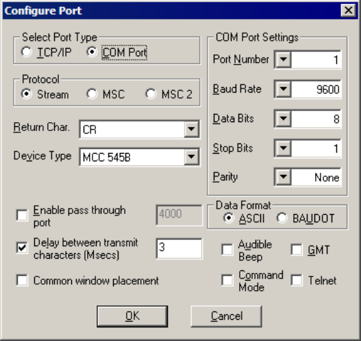
OPERATIONS
Page 94 MRC-565 Packet Data Radio Operations & Maintenance
Before starting a download be sure to set some delay between characters in the connection
configuration settings dialog box. In the box below this is checked and set to “3”. Failure to do
this can cause corruption in the file or script to be downloaded.
The following screen image shows the popup window to get to the file selection point when
sending a ".MSG" file.
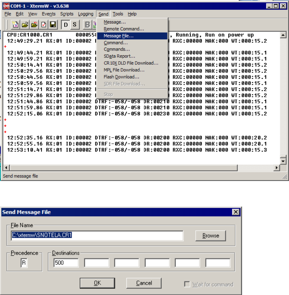
OPERATIONS
Page 95 MRC-565 Packet Data Radio Operations & Maintenance
The Send Message File window will pop up next.
Use the “Browse” button to navigate to the desired file name or type in its path directly. Enter a
message priority “A – Z” and the ID of the radio. Click on “OK” to send the message. If the file
was fragmented into more than one piece, be sure to send the pieces in proper sequence.
The radio ID in the Destination field must be set to a valid ID. This can be the radio that Xtermw
is connected to, or it can be a remote radio with Xtermw connected to a Base. Each message will
be routed to the destination radio and when the last message fragment arrives, that destination
radio will delete the old file and data tables, then download the new file and launch the new
program. The radio will create a return message to the sending radio that indicates success or
failure of the download.

OPERATIONS
Page 96 MRC-565 Packet Data Radio Operations & Maintenance
For example:
02/21/14 12:22:05 Command response received from 00500
# 02/21/14 12:19:54 CPU:CR1000.CR1 Downloaded to PakID:00001 OK
Note that the PakID is the ID of the data logger attached to the destination radio.
5.9 SDI-12 Sensors
Support for collecting data from sensors using the SDI-12 protocol is described in this document
in three sections. These are:
1. Data Collection
2. Data Logging
3. User Interface.
The MRC-565 (hereafter referred to as the radio) is a data radio whose primary use is as a
telemetry modem that acquires data from data loggers or sensors and transmits that data to a Host
Data System using the Meteor Burst RF Link protocol. The Meteor Burst link protocol uses
ionized air molecules in the Ionosphere to re-transmit radio signals beyond Line of Sight.
Legacy Systems have used the CSI CR10X and CR1000 Data Loggers as the interface to all
sensor devices. The radio periodically polls the data logger for any new data and then transmits it
to a Master Station radio as the meteor trails randomly allow a communication path. The data
logger’s record the data making it possible to remotely interrogate them for collecting data
reports if they are not stored in the central data system for some reason.
METEOR
TRAIL
IONOSPHERE
EARTHS
SURFACE
REMOTE
STATION
TO BE RECEIVED BY THE REMOTE
ALLOWS THE IDLE PROBE SIGNAL
2. THE IONIZED TRAIL OF A METEOR
IDLE
PROBE
IONOSPHERE
EARTHS
SURFACE
REMOTE
STATION
THE IDLE PROBE SIGNAL AGAIN
MASTER STATION RETURNS TO SENDING
4. THE TRAIL DISAPATES AND THE
IDLE
PROBE
IONOSPHERE
EARTHS
SURFACE
MASTER
STATION
MASTER
STATION REMOTE
STATION
CONTINUOUS IDLE PROBE
1. MASTER STATION TRANSMITS A
METEOR
TRAIL
IONOSPHERE
EARTHS
SURFACE
MASTER
STATION REMOTE
STATION MASTER
STATION
METEOR TRAIL REFLECTS THE SIGNAL
IS ESTABLISHED AS LONG AS THE
3. BI-DIRECTIONAL COMMUNICATION

OPERATIONS
Page 97 MRC-565 Packet Data Radio Operations & Maintenance
The radios can have SDI-12 sensors directly connected offering the possibility of eliminating the
data loggers in locations where the source-point data logging requirement is not required.
5.9.1 Data Collection
The data collection process usually requires a smart processor to connect to each data logger and
extract the recorded data. In many cases the data loggers have the required software to access
sensors and perform the calculations to convert the reading into engineering data values. Sensor
development has led to devices that do their own data calculations and use the simple SDI-12
protocol to send that data to data recorders.
The MRC-565 radio can collect data from SDI-12 sensors then transmit it to the central data
system. This is usually done on a periodic basis, every hour for example. The radio organizes the
data measurements into message packets called Sensor Data (SDATA) Reports for transmission
to a master station. Each SDATA report can hold from 1 to 16 data values of 16 bits each. These
can be in integer (hex) or CSI-Floating-point format. Each SDATA report has a unique group
number (0-15) and data/time tag. The 565 radio can hold up to 200 of these group reports while
waiting for meteor trail communication opportunities to deliver them to the master station, or
during brief network outages.
5.9.2 Setup
This section gives a general description of how the radio’s commands are used to adapt the radio
to the SDI-12 paradigm used by the sensors. The User Interface section below gives the details
of each radio command.
The radio commands define a Sensor Definition Table and create a data collection and
transmission schedule. The SDI-12 protocol is used to give the radio control of and access to the
sensors and their data measurements. The sensors also require commands to configure and
calibrate them. The sensor setup will be described by the documentation provided by each
Manufacturer and is not discussed here.
The Sensor Definition Table is built in the form of a two dimensional matrix with rows and
columns. There is a row for each unique combination of sensor-address and SDI-12 command
type, and columns for selecting the SDI-12 command and expected number of measurements.
Data Collection
ID
Sensor Address
Data Set Name
SDI-12
Command
Number of
Values
1
0
Weather
M1
7
2
0
Rain
M2
3
3
1
Moisture
M
5
4
2
Snow Pillow
M
4
Figure 9. Example Sensor Table
OPERATIONS
Page 98 MRC-565 Packet Data Radio Operations & Maintenance
Some sensors will output several measurements with one SDI-12 command. Others can, or will,
require several SDI-12 commands to collect all of the data measurements. The extended SDI-12
commands can be used to collect some particular measurements that are specific and pertain to
different features or capabilities of that sensor. The transparent mode will be used to control and
configure sensors.
When one sensor has several sets of data that require different SDI-12 commands to access, it
will be necessary to use the same sensor address in several rows of the table as in row 1-2 of the
example table. The row number becomes the collection ID for data collection and reporting
purposes. The columns of each row are configured parameters to define a sensor address, a data
set reference name, SDI command required and number of expected measurements.
The SDI, SEN, ID, ADDR, MTYPE,NVAL command creates the table rows.
The EVENT, GROUP, N, SDI[R:M], SDI[R:M], SDI[R:M]… command “maps” which data
values in the Sensor Table are to be combined into each SDATA group message. The number
‘N’ is the group number (1-16).
Each parameter following ‘N’ is a data value ID. There can be from 1 to 16 data values. The data
values can be pre-defined radio values (see radio HELP,EVENT command) or they can be SDI-
12 sensor measurements.
Using the pre-defined name of SDI[] in the command will specify a row [R] and measurement
number [M]. For example SDI[3:2] specifies row 3 and measurement 2. In this way, any
measurement can be reported in any group number and slot. There can be up to 16 groups with
16 values each for a total of 256 values per radio (or data collection site). The format of the
group SDATA reports are exactly the same as those created for data logger sites. Both data
logger reports and SDI sensor reports can be created for one site, but the total is limited to 16
groups and the data groups can not contain SDI measurements and Vice Versa.
As an example we could define two group SDATA reports from the Example Table:
EVENT,GROUP,1,SDI[1:1],SDI[1:2],SDI[1:3],SDI[1:4],SDI[1:5],SDI[1:6],SDI[1:7],
SDI[2:1],SDI[2:2],SDI[2:3]
EVENT,GROUP,2,SDI[3:1],SDI[3:2],SDI[3:3],SDI[3:4],SDI[3:5],SDI[4:1],SDI[4:2],
SDI[4:3],SDI[4:4]
After the Sensor Table and Group definitions are completed, they are saved in the configuration
Flash Memory with all the other radio setup command parameters.
5.9.3 Periodic Data Collection
After the Sensor Table is set up, a schedule needs to be created to tell the radio when to collect
the data and when to build and transmit the SDATA reports.
OPERATIONS
Page 99 MRC-565 Packet Data Radio Operations & Maintenance
A data collection command is periodically scheduled which uses the row number to trigger the
collection of data for that row. The data measurements that are returned by the sensor are stored
in the sensor table. Up to 64 measurements for each row can be stored.
The SDI,COLLECT,1,2,3,4,… command triggers data collection for all the rows in that
command. Once all the data is collected and stored in the table for one SDI,COLLECT command
the radio can go to the next scheduled command. There can be several commands scheduled to
collect all the data for each reporting interval.
Following the data collection commands, the commands to build and transmit each SDATA
group report are scheduled. This is the EVENT, UPDT, G command where ‘G’ is the desired
GROUP number.
The schedule is also saved in the radios configuration Flash memory. An example for our Sensor
Table might be:
SCHED,INTERVAL,1:0:0,SDI,COLLECT,1,2,3,4
SCHED,INTERVAL,1:0:0,OFFSET,15,EVENT,UPDT,1
SCHED,INTERVAL,1:0:0,OFFSET,15,EVENT,UPDT,2
This will repeat every hour and take up to 15 seconds to collect the data, then create the SDATA
reports.
To summarize: (1) the Sensor Table and Groups are defined, (2) the schedule commands are
created, (3) this is SAVE’d in the configuration Flash memory, and (4) the radio periodically
collects and then transmits the data to its Master station.
5.9.4 Data Logging
The 565 is not a data recorder, but does have the ability to log trace files. A USB memory stick
can be plugged into the front of the 565 and set up to log the maintenance port trace output. This
will log all the SDATA reports as they are created. The USB device can be exchanged for a new
one when it is filled. The USB device can then be delivered to the Customer for data analysis.
The USB device has a DOS 6.2 file format with a new log file for each day. The user will have
to provide software to extract the data from the log files.
The 565 cannot look back in this file in real-time to re-transmit old SDATA reports as of the
initial software release, but that could be implemented in the future if/when required.
5.9.5 User Interface
The MRC-565 has a RS-232 communication port for local user interface. If the breakout cable is
supplied, the 9-pin connector labeled “MNT” is the correct port. A direct connection to the front
panel of the MRC-565 USB connector can be used with a proper USB/RS-232 adapter cable.
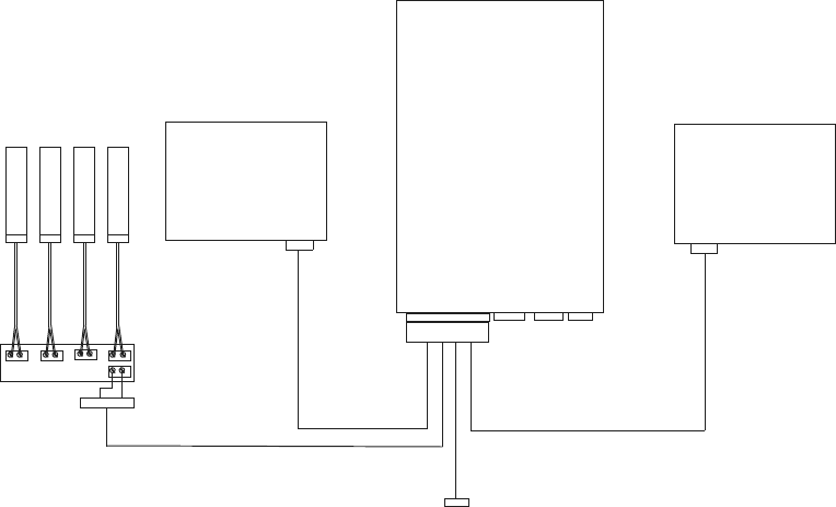
OPERATIONS
Page 100 MRC-565 Packet Data Radio Operations & Maintenance
A terminal server program, such as XTERMW.EXE provides a text-based operator command
interface to the radio Operating system. The commands required to operate the SDI-12 capability
are documented in the next section. There is a HELP command to list all commands, then the
HELP,xxxx command will give a brief description of each (xxxx) command.
A “transparent” user command is provided to let users configure their sensors if that is required.
This command takes any command format and passes it to a sensor on the SDI-12 line. The first
character of the command is the sensor address.
See the SDI,CMD,xxxx… command in the next section. This capability gives a technician the
ability to visit a site and perform some (maybe not all) diagnostic operations without
disconnecting a sensor or using the sensor Manufacturers software to communicate with the
sensor.
Since all user commands are also capable of being sent from the central host system to any radio
in the network, these commands can provide some unscheduled manipulation and status
interrogation of the SDI-12 sensors. In a Meteor burst system the use of remote commands may
require additional software such as XTERMW.EXE, DATACENTER.EXE or DDD.EXE. These
are documented elsewhere.
Figure 10. Test Bench Connection Diagram
SDI-12 Sensors
Data Logger
9 2
9=gnd
2=SDI-12
25 Pin
connector
Terminal strip
DTA
Port MNT
Port
MRC-565
Packet
Data
Radio LapTop PC
ALT
Not Available
on the MRC-565
OPERATIONS
Page 101 MRC-565 Packet Data Radio Operations & Maintenance
5.9.6 MRC-565 Commands
The following commands are used with SDI-12 Sensor data collection. The setup commands are
listed first followed by the control and status type real-time commands.
5.9.6.1 SDI
Show the Sensor Table settings and values.
5.9.6.2 SDI, SEN, N, ADDR, NOMENCLATURE, MTYPE, NVAL
Define a Sensor Table entry where:
N entry or Row number (1-64)
ADDR Sensor address (0-9) or (A-Z) or (a-z)
Nomenclature 18 character Text name for this entry
MTYPE Measurement Type (M or M1-M9 or MC or MC1-MC9)
(C or C1-C9 or CC or CC1-CC9)
NVAL Maximum number of values returned
Example setup script:
+SDI,DEL,ALL
+SDI,SEN,1,0,Measurement,M,9
+SDI,SEN,2,0,Concurrent,C,9
+SDI
Sensor Definitions
Num ADDR Measurement Name MTYPE NVAL
=== ==== ==================== ===== ====
1 0 Measurement M 9
2 0 Concurrent C 9
+
5.9.6.3 SDI, SEN, DEL, ALL
Deletes all of the entries in the Sensor Table. This is used in script files where a new
script is being loaded. If this is not done first then there may be residual data or
definitions that were not meant to be there.
5.9.6.4 SDI, SEN, DEL, N
Delete only entry ‘N’ from the Sensor Table. All other entries are left untouched.
OPERATIONS
Page 102 MRC-565 Packet Data Radio Operations & Maintenance
5.9.6.5 EVENT, GROUP, GN, SDI[1:1], SDI[1:2], SDI[1:3]…
Define a new Event Group or replace the old Event Group with this GN where:
GN New Group number (1-16)
SDI[x:y] Each entry specifies which Sensor Table entry (x) and which
measurement number (y) (1-64) to record in that slot of the
SDATA message. There is a maximum of 16 slots in each SDATA
message. They will be formatted as 16-bit CSI floating point
numbers.
Example: EVENT,GROUP,1,SDI[1:1},SDI{1:2],SDI[1:3]<CR>
5.9.6.6 SDI, COLLECT, 1, 2, 3…
This command triggers the data collection of each Sensor Table entry listed as a parameter. Up
to 10 sensor table numbers can be given in each command. The command processing will scan
the table and immediately collect all type ‘M’ sensor measurements if finds. It will start all type
‘C’ concurrent measurements it finds then wait for them to complete, and finally collect the data
from the sensors. All the data collected is stored in the Sensor Table rows for the given sensors
and can be viewed with the SDI command.
5.9.6.7 EVENT, UPDT, G
The EVENT, UPDT command runs the SDATA group building function for the G group number
given. One SDATA group report is created for each UPDT command. The SDATA builder
extracts data from the Sensor Table. This command should be scheduled after the COLLECT
command has completed gathering all the sensor data. The data measurements remain in the
table and can be looked at or transmitted again without updating if that is appropriate for the
particular sensor.
5.9.6.8 SCHED, I, TIME, ANY COMMAND TEXT
The command scheduler can hold up to 50 entries and has several options as shown by its HELP
text below.
+HELP,SCHED 05/15/14 19:05:35
SCHED Show Schedule
SCHED,DEL,N Notes: N is the sched item number
SCHED,DEL,ALL TOD can be hh:mm:ss or mm:ss or ss
SCHED,I,TOD,<cmd-string>
SCHED,I,TOD,OFFSET,TOD,<cmd-string>
SCHED,T,TOD,<cmd-string>
SCHED,T,TOD,OFFSET,TOD,<cmd-string>
OPERATIONS
Page 103 MRC-565 Packet Data Radio Operations & Maintenance
To schedule data collection for our sensors and transmission of the GROUP SDATA report we
could enter the following commands:
SCHED,I,30:0,SDI,COLLECT,1,2
SCHED,I,30:0,OFFSET,15,EVENT,UPDT,1
The first command schedules data collection of sensor table items 1 and 2 every 30 minutes and
00 seconds. The second command schedules the event group 1 to be created and send every 30
seconds with an offset of 15 seconds to give time for the data collection to complete.
5.9.7 SDI, CMD, COMMAND TEXT
Transparent Mode command. This command will output the text to the SDI-12 data line exactly
as typed with the ‘!’ character appended to the end. The first character must be a sensor address
and the remaining characters should be some valid basic or extended SDI-12 Command. The ‘!’
character should not be entered.
Example: SDI,CMD,0V<cr>
A list of the basic SDI-12 commands is given at the end of this document. Some Sensor
Manufacturers have their own special commands for setup and calibration which this transparent
mode is designed to support. These commands are not saved in the radio configuration flash
memory so if the sensor does not retain it in a power cycle it will be lost. If this command is
entered as a real-time-scheduled command it will be saved in the configuration flash memory.
5.9.8 SDI, TRACE, {OFF/ON}
The SDI,TRACE command is useful for debugging the setup and operation of the radio with the
sensors.
The example below shows a data collection from a sensor testing device that was set up to
emulate a sensor. The trace output can get to be a lot of information and should not be left on for
long periods or its output can overrun the radio output memory and cause the radio to reset. Be
careful using this command option.
Characters enclosed in the “<>” characters are transmitted out of the radio. Characters enclosed
in the “[]” characters are received by the radio. The time tag is in hundredths of seconds.
Example with TRACE,ON
+sdi,collect,1
20:14:44.59 <BREAK>
20:14:44.60 <MARK>
20:14:44.62 <0M!>
20:14:44.69 [00056(cr)(lf)]
OPERATIONS
Page 104 MRC-565 Packet Data Radio Operations & Maintenance
20:14:49.22 [0(cr)(lf)]
20:14:49.23 <BREAK>
20:14:49.24 <MARK>
20:14:49.27 <0D0!>
20:14:49.34 [0+0.0(cr)(lf)]
20:14:49.35 <BREAK>
20:14:49.36 <MARK>
20:14:49.40 <0D1!>
20:14:49.46 [0+1.0(cr)(lf)]
20:14:49.48 <BREAK>
20:14:49.49 <MARK>
20:14:49.52 <0D2!>
20:14:49.59 [0+2.0(cr)(lf)]
20:14:49.60 <BREAK>
20:14:49.61 <MARK>
20:14:49.64 <0D3!>
20:14:49.71 [0+3.0(cr)(lf)]
20:14:49.72 <BREAK>
20:14:49.73 <MARK>
20:14:49.77 <0D4!>
20:14:49.83 [0+4.0(cr)(lf)]
20:14:49.85 <BREAK>
20:14:49.86 <MARK>
20:14:49.89 <0D5!>
20:14:49.96 [0+5.0(cr)(lf)]
5.9.9 SDI-12 Command/Response List
Name Command Response
Break Continuous spacing for 12 ms None
Acknowledge Active a! a<CR><LF>
Send Identification aI! allccccccccmmmmmmvvvxxx...xx<CR><LF>
Change Address aAb! b<CR><LF> (support for this command is required
only if
the sensor supports software changeable addresses)
Address Query ?! a<CR><LF>
Start Measurement* aM! atttn<CR><LF>
Start Measurement + CRC* aMC! atttn<CR><LF>
Send Data aD0! … aD9! a<values><CR><LF> or
a<values><CRC><CR><LF>
Additional Measurements* aM1! … aM9! atttn<CR><LF>
Additional Measurements + CRC* aMC1! ... aMC9! atttn<CR><LF>
Start Verification* aV! atttn<CR><LF>
Start Concurrent Measurement aC! atttnn<CR><LF>
Start Concurrent Measurement + CRC aCC! atttnn<CR><LF>
Additional Concurrent Measurements aC1! … aC9! atttnn<CR><LF>
Additional Concurrent + CRC aCC1! ... aCC9! atttnn<CR><LF>
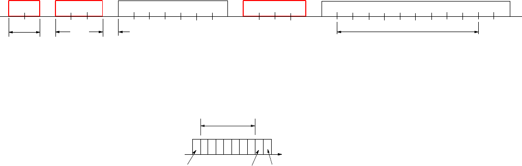
OPERATIONS
Page 105 MRC-565 Packet Data Radio Operations & Maintenance
Continuous Measurements aR0! ... aR9! a<values><CR><LF> (formatted like the D commands)
Continuous Measurements + CRC aRC0! ... aRC9! a<values><CRC><CR><LF> (formatted like the D
commands)
*These commands may result in a service request.
5.9.10 Serial Port Command and Response Diagrams
Figure 11. Data Port Byte Stream Timing and Data Byte Format
The Diagrams above summarize the type of command/response that is used in the SDI-12
protocol. The data rate is always 1200 baud. The BREAK signal is a minimum of 12ms at +5V
followed by at least 8.33ms of a MARK signal at 0V. The purpose of the BREAK is to wake up
all the sensors on the line.
The “line” is a single wire in tri-state mode where the Recorder is master and the Sensors are
slaves. Only one device can transmit at a time, the master device always initiates
communication, and the slaves always respond to commands addresses to them, are received
correctly, and are valid in format and content.
The first byte of each command and response is a 1-byte sensor address. Valid addresses are 0-9,
A-Z and a-z. The last byte of a command is always a ‘!’ character. Response strings always
begin with the sensor address and end with <cr><lf>.
Each byte has 1 start bit, 7 data bits, 1 parity bit and 1 stop bit. The start bit is +5V. The data and
parity bits are Negative polarity where a ‘0’ is +5V and a ‘1’ is 0V. The stop bit is 0V. The bytes
that a device sends should have no space between them, but the protocol allows up to 1.66ms
between bytes.
low power command
wake-up command acknowledge send data command data report with one value
break a
mark M!\r \n aD 0 !a
a+12 3 4
05.
6 7 \r \n
001
12ms 8.33
ms wake
up
delay
15-100ms
always has +/- sign but may not
have the decimal point if it is an
integer value. So it can be from
2 to 9 bytes including sign and
decimal point.
MASTER
SLAVE
varies from 1 to 7 digits
S1 2 34 5 6 7 S
Ptime
data bits
even
parity
bit
Start
bit (high) Stop
bit(low)
Least significant bit
is sent first
Data Port Byte Stream Timing Diagram
Data Byte Format
+5V = 0
0V = 1
OPERATIONS
Page 106 MRC-565 Packet Data Radio Operations & Maintenance
Sensors should respond to a command in 15ms, but they can take up to 100ms to wake up from a
sleep state and respond to the first command after the BREAK. The master (in this case the
MRC-565 Radio) will retry commands if it gets no response. The first timeout is 100ms and
subsequent retries will time out after 20ms. The MRC-565 basic timing internal clock is 10ms
per “tick” so all of the timing is rounded up to the next 10ms tick.
5.10 Generic Data Logger
The MRC-565 includes a set of device drivers for its serial ports. These have been customized
for various external devices over the years as the requirements became known. The SDATA
command was created to allow a simple text-based interface to send data groups to the MRC-565
for transmission to the master. Any customer that could configure their data report to meet this
format could interface his data logger with no change in the MRC-565 software. From 1 to 16
groups can be input, and there can be from 1 to 16 sensors per group. Each sensor data value is
formatted into a 16-bit binary value for transmission, then converted to engineering units by the
Data Center or Host software.
Some date loggers have a complex and non-configurable interface protocol, and cannot meet any
of the currently implemented protocols, but they can output data reports on a serial port as if it
were connected to a line printer. The GENERIC data logger driver has been created for this type
of interface. Some things can be setup by user commands to configure the report parsing, within
a limited set of constraints, and allow the MRC-565 to create SDATA type messages from the
ASCII text reports.
The following sections describe what can be done to adapt the MRC-565 to a variety of report
formats.
5.10.1 Typical Report Formats
A typical report printed by a data logger has one line, or a set of lines for each report. There are
usually two types, single-line reports, and multiple-line reports. An example of each type would
be as shown below:
Single line report examples:
123.4 19.8 33 99 -1089.45 ….<cr><lf>
or
10/14/02 09:15:00 +123.4 +19.8 +33 +99 -1089.45 ….<cr><lf>
Note that the report ends with carriage return and linefeed characters, and may or may not print a
date and/or time. The data fields are usually separated by blanks, and the data values may or
may not contain a sign or decimal point. The line is usually output by the data logger as the
report is placed into the devices' memory in real-time. There is no provision for error checking,
but if the serial port cable is wired correctly with shielding, etc., it may be reliable enough.
OPERATIONS
Page 107 MRC-565 Packet Data Radio Operations & Maintenance
Multiple line report examples:
No time tag With time tag With Sensor Labels
123.4<cr><lf> 10/14/02 09:15:00<cr><lf> Date/Time: 10/14/02
09:15:00<cr><lf>
19.8<cr><lf> +123.4<cr><lf> AC Voltage +123.4<cr><lf>
33<cr><lf> +19.8<cr><lf> DC Voltage +19.8<cr><lf>
99<cr><lf> +33<cr><lf> Pulse Count +33.0<cr><lf>
1089.45<cr><lf> +99<cr><lf> Error Code +99.0<cr><lf>
-1089.45<cr><lf> Pressure -1089.45<cr><lf>
If the generic device driver software is set up to "poll" for data by outputting a command string,
then the data report may need to be processed as a multiple line report even when the data logger
outputs only one line. This can happen if the data logger "echoes" the polling command. The
generic device driver will "see" the echoed command as part of the data report response.
5.10.2 Setup and Configuration
The MRC-565 generic data logger driver can configure the following:
Report type (single-line, multi-line)
Group ID Number (Auto generated, Location in report, Fixed)
Date (Auto generated, Location in report, Format of date characters)
Time (Auto generated, Location in report, format of time characters)
Sensor Values (Auto free-format, Location in report)
Poll command definition
Start-of-report definition
Remote Commands
Each operator command begins with the command name and port number as shown in the
following command. Example: GENERIC,1,TYPE,AUTO.
Selecting The Generic Protocol for a Port
The ASSIGN command is used to define the device driver to use on a port. As an example, the
command ASSIGN,DTA,1,GENERIC,5 will assign the DTA function to use port 1 (the DATA
port), and run the GENERIC data logger device driver with a 5 second timeout. Use the
SETBAUD,DTA,9600 command to specify a baud rate for the port. Any port (0-3) can be used,
and multiple ports can select the generic device driver at the same time. Port 0 is usually
reserved for an operator terminal, and port 3 is an internal GPS port. That means ports 1 and 2
are open for external devices.
OPERATIONS
Page 108 MRC-565 Packet Data Radio Operations & Maintenance
5.10.3 Viewing the generic device driver setup
Enter the GENERIC command with no parameters to display the current setup for all active
ports. The following example response shows a typical setup with only port 2 set up for generic
operation.
+generic 12/11/01 10:54:32
Rpt Group............ Date......... Time......... Sensor.......
P Type Type N L# S E Type L# S E Type L# S E Type L# S E
= ==== ===== == == == == ==== == == == ==== == == == ==== == == ==
2 LINE FIXED 02 00 00 00 LINE 01 10 16 LINE 01 18 25 LINE 02 22 32
Report:DATE/TIME: Date:YY/MM/DD Time:HH:MM:SS
From the report one can see that only port 2 is configured, and the other ports have a report type
of OFF. The Group section has 5 fields: Type, Number, Line number, Start column, End column.
This line shows the group is fixed at group number 2. The Date, Time and Sensor sections each
have 4 fields: Type, Line number, Start column, End column. The date is on line 1 between
columns 10 and 16. The time is on line 1 between columns 18 and 25. The first sensor value is
on line 2 between columns 22 and 23, and the remaining lines of the report will each contain 1
sensor value between columns 22 and 23.
The line following the port 2 line shows additional options for that port. Shown here are the
start-of-report string, the date format, and the time format. Only options selected will be shown
on this line. All of the settings in this generic driver table are saved in the non-volatile memory
of the MRC-565.
Report Type: GENERIC,P,TYPE,{AUTO,LINE,OFF}
This command selects whether the report is in a single line format or multiple line format.
AUTO specifies single line with free-format, and LINE specifies the multiple line format. The
OFF option is provided to turn off a previously set-up port.
Reports are parsed from sets (bursts) of characters read into a 1024 byte buffer. The end of the
data set will be signaled by a timeout period with no more characters being received. The
timeout is taken from the ASSIGN command described earlier. When each set is finished being
processed, the input buffer is cleared to wait for the next set of characters.
5.10.4 AUTO Format
For the simplest AUTO report type, with no group number, date or time stamp, each line will be
parsed from left to right using blanks and commas as delimiters between data values. The
carriage return and line feed characters are also ignored. The first group report will take up to 16
data values, then the next 16 go into group 2, the next 16 into group 3, and so on until the last
character has been reached.
OPERATIONS
Page 109 MRC-565 Packet Data Radio Operations & Maintenance
For example see the following set of characters:
1 2 3 4 5 6 7 8 9 10<cr><lf>
11 12 13 14 15 16 17 18 19 20<cr><lf>
21 22 23 24 25 26 27 28<cr><lf>….timeout
This character set will create two groups where the values 1-16 will go into group 1, and the
values 17-28 will go into group 2. Each report will be time and date stamped using the current
time of the MRC-565. Up to 256 data values can be parsed into 16 groups using this format as
long as the total number of characters in each set does not exceed the buffer size( including all
delimiters).
An Example of an AUTO format with a date and time stamp is:
10/15/01 12:00:00<cr><lf>
1 2 3 4 5 6 7 8 9 10<cr><lf>
11 12 13 14 15 16 17 18 19 20<cr><lf>
21 22 23 24 25 26 27 28<cr><lf>….timeout
Another example:
10/15/01 12:00:00 1 2 3 4 5 6 7<cr><lf>
8 9 10 11 12 13 14 15 16 17<cr><lf>
18 19 20 21 22 23 24 25 26 27<cr><lf>
28<cr><lf>….timeout
For these two formats with date and time above, the port should be setup for an AUTO report
type, then select a date and time option that locates the date and time fields on line 1. Use the
sensor setup command to indicate that the 1st sensor is located either on line 2 as in the 1st
example or on line 1 as in the second example. The AUTO formatting will use the first two
"fields" found as the date and time, then use the remaining fields as the sensor data.
5.10.5 MULTI-LINE Format
For the LINE (multi-line) report type, the first "line" includes all the bytes from the beginning of
the buffer to the first carriage return. Any line feed characters are ignored. The 2nd line is all the
bytes from one past the carriage return to the next carriage return and so forth to the end of the
set of characters. The report ends with the last character received prior to the timeout period
with no more bytes being received. This example shows that each line holds only one sensor
value. Reports with both labels and data that have multiple values per line are not yet supported
by the generic driver, but it is possible to report multiple sensors per line when there are no line
labels present on each line.
One example of a multi-line report from the AANDERAA 3660 data logger is shown below:
Date/Time: 1.12.11 18:57:50
OPERATIONS
Page 110 MRC-565 Packet Data Radio Operations & Maintenance
00 Battery Voltage 12.7 Volt
01 Reference 699
02 Wind speed 79.4 m/s
03 Wind gust 79.4 m/s
04 Wind direction 359.6 Deg.M
05 Air temperature 48.8 Deg.C
06 Relative humidity 101.6 % RH
07 Air pressure (QNH) 1089.6 hPa
08 Visibility 3002.9 m
09 Sunshine duration 1023.0 min
10 Net atm. radiation 2120.4 W/sqm
11 Rainfall 204.6 mm
From the above report one can see that the date is on line 1 in columns 12-19, and is in year-
month-day format. The time is also on line 1 in columns 21-28. Sensor data then starts on line 2
and repeats on subsequent lines in columns 25-30. The label fields are ignored.
Group Number: GENERIC, P, GROUP, AUTO
GENERIC, P, GROUP, LINE, Line Number, Start, End
GENERIC, P, GROUP, FIXED, Line Number
The AUTO group numbering will start at group number 1 and increment by 1 for each 16 sensor
values. The LINE option allows the group number to be within the data at the given line number
and between the given start and end column numbers. The FIXED option will use the Line
Number parameter as the first group number then increment by 1 for each 16 sensor values.
Date: GENERIC, P, DATE, AUTO
GENERIC, P, DATE, LINE, Line Number, Start, End,{FORMAT}
The AUTO date option will use the MRC-565 internal Date. The LINE option allows the date
to be within the data at the given line number and between the given start and end column
numbers. The FORMAT is optional, and shows a "template" of the date format. It can be
"MM/DD/YY", "YY/MM/DD", "MMDDYY", "YYMMDD". If the format is not given it will
default to the "MM/DD/YY" format.
Time: GENERIC, P, TIME, AUTO
GENERIC, P, TIME, LINE, Line Number, Start, End,{FORMAT}
The AUTO time option will use the MRC-565 internal time. The LINE option allows the time to
be within the data at the given line number and between the given start and end column numbers.
The FORMAT is optional, and shows a "template" of the time format. It can be "HH:MM:SS",
"HH:MM", "HHMMSS", "HHMM". If the format is not given it will default to the
"HH:MM:SS" format. The MRC-565 SDATA reports are only time-tagged with month-day-
hour-minute. Year and seconds are not transmitted.
Sensor Values: GENERIC, P, SENSOR, AUTO
GENERIC, P, SENSOR, AUTO, Line Number, Start
GENERIC, P, SENSOR, LINE, Line Number, Start, End
OPERATIONS
Page 111 MRC-565 Packet Data Radio Operations & Maintenance
In AUTO mode, sensor values are delimited by blanks or commas and there may be several per
line. If the line number parameter is not given (example 1 above) then data is assumed to start
on the 1st line of the report. If the line number is given, data can start on other than the 1st line.
In addition, if the start parameter is given, data can begin in a column other than the 1st column.
For example you may have a report such as the following:
10/14/02 09:15:00 +123.4 +19.8 +33 +99 -1089.45 ….<cr><lf>
Notice it has a date, time, then data values on the same line. In this case you would use a
GROUP,P,SENSOR,AUTO,1,18 command to locate the start of the sensor data, and use the
"auto" method of locating the rest of the data.
In LINE mode, Sensor values will start on the given line number and start-end columns, then
will repeat, either in free format, or one value per line, depending on the report type.
Polling: GENERIC, P, POLL, Poll String, Interval
The polling feature can be used for data loggers that do not print a data report unsolicited, but
require some command string to be sent to request the next report. The poll string can be any
printable ASCII characters up to 20 bytes in length. The INTERVAL parameter is given in
decimal and is the number of seconds between outputting the poll string. If a poll is output, the
response string from the data logger will be parsed in the same manner as when there is no poll
string required. If the data logger echoes the poll string, this will look like part of the report and
must be accounted for in the setup. To handle data loggers that need to wake up from a low-
power mode, the poll string will be preceded by a carriage return and line feed, and the poll
string will be followed by another carriage return and line feed.
Polling using binary (non-printable-ASCII) characters is not yet supported.
Start of Report: GENERIC, P, REPORT, Report String
The report string allows the definition a fixed string of printable ASCII characters that is at the
beginning of each new set of report characters. This is useful for ignoring bursts of non-report
text. Each report is started with the report string and ends with the timeout parameter. If the
cable between the data logger and MRC-565 is connected part way through the output of one
report, and the report string text is "missed", then a partial report will not be created.
Remote Commands: GENERIC, P, COMMAND, Command String
Some support for remotely commanding and configuring a generic data logger is provided using
this command format. If the data logger can accept commands as a single line of text (no
embedded <cr><lf>) without having to be locally present at the data logger to type keys into a
menu, then this capability may be just the ticket. When a remote command is received by the
MRC-565, it will output the Command String bytes to the data logger preceded and followed by
OPERATIONS
Page 112 MRC-565 Packet Data Radio Operations & Maintenance
a carriage return and line feed. The response text, up to 1024 bytes, will be captured and
returned to the originating modem as a remote command response message.
Example Script:
generic,1,type,auto
generic,1,group,auto
generic,2,type,line
generic,2,group,fixed,2
generic,2,sensor,line,2,22,32
generic,2,date,line,1,12,19,YY/MM/DD
generic,2,time,line,1,20,29,HH:MM:SS
generic,2,poll,off
generic,2,report,Date/Time:
generic,3,type,off
generic,0,type,off
assign,dta,off
assign,alt,off
assign,dta,2,generic,5
setbaud,2,9600
assign,alt,1,generic,2
setbaud,1,9600
generic
save
5.11 Event Programming
The MRC-565 supports customer-programmed event logic. Discrete and analog inputs can be
monitored by the event program to detect "events" which then perform a defined "action".
Actions may include the controlling of discrete output signals, incrementing counters, setting
timers, transmission of canned messages and issuance of various reports. This means that
customers are somewhat independent of factory reprogramming from MRC and that MRC-565
behavior can be readily modified in the field. It also means that operators now have limited
power to make the MRC-565 react to various field-programmable conditions.
The operator sets up the event program when installing the MRC-565 or during maintenance and
operation. Because the event program is implemented via operator commands, it can be entered
not only at a local maintenance console, but also via the remote command capability. The event
programs are stored within a non-volatile table in the MRC-565 battery-backed-up RAM. They
are not lost due to external power failure. When the external power is restored, they will be
enabled to respond to events again.
Programming is usually done by creating a "script file" of the required event commands, and
loading these into the MRC-565 using XTERM or any other terminal emulator software.
OPERATIONS
Page 113 MRC-565 Packet Data Radio Operations & Maintenance
Several input/output lines are available directly from the processor card of the MRC-565
modems. In addition, an I/O expander card (XIO) can be optionally used which uses 3 lines to
implement a high-speed serial link for accessing the signals of the expander card.
Refer to APPENDIX D for details on Event Programming.
MAINTENANCE
Page 114 MRC-565 Packet Data Radio Operations & Maintenance

MAINTENANCE
Page 115 MRC-565 Packet Data Radio Operations & Maintenance
MAINTENANCE
MAINTENANCE
Page 116 MRC-565 Packet Data Radio Operations & Maintenance
6 Maintenance
Maintenance of the MRC-565 has been reduced dramatically because of the use of a Software
Define Radio (SDR). Proper operation is guaranteed through the verification and or adjustment
of a few software and hardware parameters. These parameters are described in the following
sections.
6.1 Script Files
It is critical that the proper script files are loaded before operation begins. These script files
configure the MRC 525 for operation in its specific location. Script files are loaded using
XTERM and can be enter from either the front panel COM port or the Ethernet connector. This
can be done either locally or at a remote connection that has an Ethernet connection to the
Master. Refer to the XTERM manual for details on loading script files.
Of all the parameters that are entered through the script files, only three are unique to each
station. These are:
ID
SERIAL NUMBER
SITE NAME
It’s best to setup script files for each Master with these three parameters and then use and
INCLUDE STATEMENT to add all the common parameters as a file name.
If all are blinking, the internal Power Supply must be working properly, however it’s a good idea
to measure this voltage as noted in the next step.
6.2 Measuring Voltage Levels
There are several voltage regulators on the CMU board. All have test points for measuring
values. A list of test points and there location is shown below.
In addition the following command can be used to verify several of the voltages:
SCALE
TP TABLE
MAINTENANCE
Page 117 MRC-565 Packet Data Radio Operations & Maintenance
6.3 Setting Up and Calibrating the MRC-565 Radio Parameters
6.3.1 CMU Adjustments
There are two calibration commands required to set up a CMU to make the radio portion
function properly. These adjustments are set up and saved in the factory or repair center and
require the use of calibrated RF test equipment. These commands are not to be used at the
installation site. A special password sequence must be used to save a new value to any of the
parameters. For troubleshooting purposes, these values can be overwritten on a temporary basis
without the password sequence.
The following values are stored in EEPROM, and are not changed in any operational
circumstance, including factory default command or loading a new operating system. Use the
following commands to view and change these parameters.
CAL Prints out the current cal values
CALRAND Returns value for use in saving CAL parameters
Specific CAL parameter commands:
1. CAL, FREQCAL,nnn Calibrates the freq of the 19.2MHz TCXO
2. CAL, ADCGAIN,nnn Calibrates the ADC1 (J2) rx sig strength, default 47
It’s a good idea to measure and record the 19.2 MHZ Reference Oscillator (TCXO) . Connect a
scope probe connected to TP and plugged into the BNC connector of a counter with a stable
clock reference (<1 PPM) to make this measurement. The oscillators must be within +/- 2PPM
of the desired frequency of 19.20 MHZ. AT 19.2 MHz this is about +/- 5 Hz. If any frequency is
off by more than 5 Hz, you must calibrate it with the following command:
CAL, FREQCAL,nnn
Change nnn around the value 510 to achieve the desired results.
The RSSI values for the receiver can be adjusted by connecting a calibrated signal generator to
each receiver input and the typing MM to read the value the values in DB. You should adjust
the RSSI value at an input level of -106 DBM at the receiver input. At this level MM should
read -106.
You can calibrate the readings by connecting a signal generator to RX Input at J1 and using the
following commands to adjust the gain number.
CAL, ADCGAIN,nnn Calibrates the ADC rx sig strength, default 47
MAINTENANCE
Page 118 MRC-565 Packet Data Radio Operations & Maintenance
The other cal parameters should not be changed.
Once you enter the Cal parameters noted above, you should save these values, so that when the
SW reboots or power is removed from the MRC 525, the parameters are saved. To SAVE Cal
parameters enter the following commands:
CALRAND to obtain a CALRAND#
CAL,SAVE,CALRAND# to save the values
Once you have saved these parameters, enter the following command to display the cal
parameters.
CAL
Record the results.
6.3.2 Power Amp Adjustments
The MRC-56500301 Power Amplifier is factory tuned to the customer specific frequencies at the
factory. These parameters should not be changed in the field.

APPENDIX A: COMMANDS
Page 119 MRC-565 Packet Data Radio Operations & Maintenance
APPENDIX A: COMMANDS
APPENDIX A: COMMANDS
Page 120 MRC-565 Packet Data Radio Operations & Maintenance
APPENDIX A: COMMANDS
All implemented MRC-565 commands are listed in the Table below alphabetically for ease of
reference. However, many commands are used in conjunction with others. These functional
groups are given below. You may also type HELP or HELP,command to receive an
explanation of any listed command.
The commands with a * in front are stored in Parameter Memory. The most critical commands
are in BOLD text.
STATION CONFIGURATION
COMMANDS
STATUS
COMMANDS
MESSAGE
COMMANDS
*ASSIGN
RCT
BINS
CANMSG
REMOTE TYPE
CLS
CANMSG MODE
*CHANNEL
RXTYPE
CONFIG
CANMSG OFF
*CHECKIN
SAVE
*HOURLIES
COMPRESSION
CLOSE PORT
SCALE
MEM
DEL MSG
CONNECT
SCHED
MODE
DQE RXQ
DATE
SERIAL
MON
DQE TXQ
*DESTINATION
*SET BAUD
MONOFF
FLUSH MSG
*DEVICE
*SNP
NETMON
FLUSH RXQ
*DUTY CYCLE
*SOURCE RELAY
STAT
FLUSH TXQ
HOST MODE
START
*STAT TIME
*HOLD
*ID
STOP
T
MESSAGE
IP
STT
TEST
*MSG
IPCONFIG
SUBST
*PRINT
LOGOFF
TIME
REMCMD
LOGON
TIME ZONE
*LOS CHECKIN
*TXLIMIT
POSITION LOCATION COMMANDS
*MODULATION
*POS
RED
APPENDIX A: COMMANDS
Page 121 MRC-565 Packet Data Radio Operations & Maintenance
NEW PASSWORD
IPC
POSRPT
RTCM
OPEN PORT
S”n”
PASSWORDMODE
MODE CONTROL COMMANDS
MASTER SIMULATOR COMMANDS
*CORPAT
*HALF DUPLEX
*P
*FULL DUPLEX
*ROLE
MAINTENANCE COMMANDS
DUAL MASTER STATION COMMANDS
BOOT
SHOW TXQ
SWCTL
RESET
SMS
REV
UPDT
UTILITY COMMANDS
SHOW RXQ
HELP
DATA LOGGER COMMANDS
SDATA
$PENTM
CR10X COMMANDS
CR10X
CR10X,ORDER
CR10X,SETPTR
CR10X,ACQMODE
CR10X,REGISTER
CR10X,SIGNATURE
CR10X,GROUP
CR10X,RESET
CR10X,STAT
CR10X,INTERVAL
CR10X,SCALE
CR10X,TIME
CR10X,MAXQ
CR10X,SECURITY
CR10X,UPLOAD
MASTER MODE COMMANDS
*BASE
POLL
SHOW RXQ
CONFIGURATION
PRG
SHOW TXQ
LISTM
REMOTE STAT
SML
APPENDIX A: COMMANDS
Page 122 MRC-565 Packet Data Radio Operations & Maintenance
MM
*REPEATER
SMS
NET
SHOW REMOTES
* Parameters/settings specified by these commands are stored in Parameter Memory (CPM). Changes specified by these commands
take effect immediately but are lost when the unit is rebooted unless the SAVE command is issued to write the changes to the non-
volatile Flash memory. Changing the unit ID automatically saves the entire configuration.

APPENDIX A: COMMANDS
Page 123 MRC-565 Packet Data Radio Operations & Maintenance
MRC-565 Command List
MRC-565 COMMANDS
TABLE
COMMAND
DESCRIPTION
PARAMETERS
RANGE
*ASSIGN
{,function,port,protocol
{,timeout}}
NOTE
{function, port and protocol}
information for all ports
(except internal port 3) are
stored in CPM; this
information for port 3 and all
timeout information is stored in
RAM.
Control allocation of user interface functions among
physical device channels. When no parameters are
entered, displays I/O configurations. Port definitions
are as follows:
Port I/O Connector
0 OPERATOR PORT
1 DATA PORT
2 AUXILIARY PORT
3 (internal) DIAGNOSTICS PORT
Port Ethernet / USB Connector
4-7 ETHERNET1 (IP PORT
4000)
NOTE
It is possible to “lose control” of the MCC-565
software by assigning control functions to ports with
no devices attached or by turning off control
functions. For example, if you turn off the Operator
Port (ASSIGN,MNT,OFF), you will not be able to
enter commands or view printouts from the MRC-
565. You must open the Power Cycle the MRC-565
to enable the Operator Port.
function = user
interface function
port = physical device
channel
protocol = link level
protocol
MNT, DTA,
ALT,
POS,E1F1,E1F
2,E1F3,E1F4,C
R10X,CR1000
0=OPERATO
R,1=DATA,2=
AUX,
4-7= Ethernet
ASCII,MSC,M
SC2,PKT,FWS
,CR10X,CR10
XTD,CR1000,
PAKBUS,SER
PKT,APCL5,G
PS,RTCM,M1
2RTCM,M12D
IFF,TRAN,UA
IS,GYRO,SOU
NDER,PHAR
OS,H350,DIR
ECT,GENERI
C,AEI,HOTB
OX,
drivers.MPL

APPENDIX A: COMMANDS
Page 124 MRC-565 Packet Data Radio Operations & Maintenance
MRC-565 COMMANDS
TABLE
COMMAND
DESCRIPTION
PARAMETERS
RANGE
timeout in seconds
0 – 32767
ASSIGN,RXn,Channel,Proto
col
RXn = Receive Number 1,2,3. (All use same ADC)
Channel = Channel Number
Default is all RX1, RX2, and RX3 assigned
Refer to Channel Command to set frequencies
Channel = 0 to 20
Protocol =
OFF,MBNET
*BASE{,nnn,nnn}
Set/display range of Master Station IDs reserved for
use as Base Stations. In MB networks set BASE to
OFF.
nnn = lowid,highid
OFF = no Bases
2 – 253
BINS
Print link distribution statistics
BOOT
Cold start of Station software. All volatile memory
is lost.
CANMSG,name,len{,Qsize}{,
count}
Automatically generate a test message of specified
length that repeats until turned off with CANMSG
OFF command. You can compose the message by
entering only the destination name (not message
length or minimum queue depth). Destination node
must be a neighbor node. CANMSG cannot contain
more than 25 messages in its queue. If the number of
canned test messages in queue falls below minimum
queue depth, additional canned messages will be
injected.
nnnn = Station ID
Master = 1 – 4095
Remote = 256 – 4095
len = number of
characters in message
Qsize = min. # of
canned messages in
queue
count = total number of
canned messages to
generate
1 – 4095
1 – 3000
0 – 25
0 – 9999
CANMSG MODE {,mode)
Set reception of canned test messages to two of the
following states:
PRINT – print all test messages
NO PRINT – does not print test messages
mode = PRINT
NO PRINT
CANMSG OFF,nnnn
Turn canned test message mode off
nnnn = Station ID
Master = 1 – 245
Remote = 256 - 4095
1 – 4095

APPENDIX A: COMMANDS
Page 125 MRC-565 Packet Data Radio Operations & Maintenance
MRC-565 COMMANDS
TABLE
COMMAND
DESCRIPTION
PARAMETERS
RANGE
CHANNEL
Shows the Active Transmitter and Receiver
frequency and the frequency table where up to 21
frequency channels can be defined.
There are three frequency bands.
1-
CHANNEL,xxx.xxxx,yyy.yyy
y,aa,bb
Select Frequencies, Modulation Value, and Channel
for the Transmitter and the Receiver.
xxx.xxxx= Transmitter
Frequency
yyy.yyyy= Receiver
frequency
aa = mod_val
bb = Channel Table
Channel Number
xxx.xxxx= 40.000
– 50.000 MHz
yyy.yyyy=40.000 –
50.000 MHz
aa= 1 - 6
aa= 1-6
bb= 0 - 20
CHANNEL,zz
Sets operating Channel from the list frequency
channels under frequency table.
zz = Channel Table
Channel Number
zz= 0 - 20
*CHECKIN{,ii}
Select check-in interval in seconds
ii = interval
1 – 65535
CLEARBINS
Clear hourly bins
CLEARLINKSTAT
Clear link stats
CLOSE PORT,function
{,function,…}
Close specified MRC-565 port from operation. You
can enter more than one port name to close, using
commas to separate the names on the same line.
CAUTION
The OPEN/CLOSE PORT commands directly
affect MRC-565 network activity and message flow.
Do NOT use these commands unless directed to do
so by your System Administrator.
function = user
interface function
RS-232
functions
MNT, POS,
ALT, DTA
Ethernet1 func.
E1F1, E1F2,
E1F3, E1F4
USB functions
U1F1, U1F2,
U1F3, U1F4
CLS
Print current values, then clear link statistics (see

APPENDIX A: COMMANDS
Page 126 MRC-565 Packet Data Radio Operations & Maintenance
MRC-565 COMMANDS
TABLE
COMMAND
DESCRIPTION
PARAMETERS
RANGE
LINKSTAT).
CONFIG,{ }
Show current configuration parameters report.
NOTE
Configuration in CPM may differ unless the SAVE
command is used after configuration changes are
made.
NONE
ALL
SCRIPT
L:ists Summary
Table of
parameters
Lists all
parameters in
list format
Lists all
parameters in a
SCRIPT format
CONFIGURATION
List major Master Station configuration settings.
CONNECT,{id1…id10}
Limits Remote-to-Master connectivity for lab and
field network configuration. Up to 10 Master IDs
can be set. The radio will only communicate with the
other radios in its connect list.
id = Master Station
OFF = no limitation
1 – 65,500
CORPAT
Without parameters, display report of available
correlation patterns and indicate usage.
CORPAT,RX,action
{,pppp...}
Define Receiver correlation patterns to recognize.
Pattern 1 is the default and is the only pattern
recognized if no others specified. Up to 16 pre-
defined patterns are recognized.
action = ON – define
patterns or
OFF – use only default
pattern
pppp = pattern number;
ALL means recognize
all patterns
1 – 8
CORPAT,TX,pppp
{,ALWAYS}
Define Transmitter correlation pattern to send.
Pattern 1 is the default and is the only pattern
recognized if no other specified. Up to 16 pre-
defined patterns may be used.
pppp = pattern number
ALWAYS means use
specified pattern
instead of received
1-- 8

APPENDIX A: COMMANDS
Page 127 MRC-565 Packet Data Radio Operations & Maintenance
MRC-565 COMMANDS
TABLE
COMMAND
DESCRIPTION
PARAMETERS
RANGE
pattern
CR10X
Display CR10X configuration parameters
CR10X,ACQMODE,mode
Set CR10X acquisition mode - Get all reports since
last UPDT
mode =
ALL – get all reports
since last update
CURRENT – get
only the current data
report
LAST,n – get last “n”
data reports
CR10X,GROUP,source
Specify source of data report group assignment.
source =
565 – 565 assigns
group numbers;
CR10X internal group
number matches data
array
CR10X – CR10X
assigns group
numbers; 565 gets
group number from
first sensor
CR10X,INTERVAL,n
Acquisition scan interval in seconds. OFF disables
acquisition scan
n = seconds
0 – 32767
CR10X,MAXQ,nnn
Set maximum number of reports to queue for each
scan of the CR10X
nnn = number of
reports
1 – 200
CR10X,REGISTER,n{,ddd}
Read/Set internal storage register.
n = register number
ddd = value
1 – 28
Signed floating
point number
(see CR10X
manual)

APPENDIX A: COMMANDS
Page 128 MRC-565 Packet Data Radio Operations & Maintenance
MRC-565 COMMANDS
TABLE
COMMAND
DESCRIPTION
PARAMETERS
RANGE
CR10X,RESET
Reset CR10X internal error counters to zero
CR10X,SCALE,type
Define sensor scaling type.
type =
545C – data scaled in
integer hexadecimal
units
CR10X – data scaled
in Campbell Scientific
floating point format
CR10X,SECURITY,nnnn,
nnnn,nnnn
Enter CR10X Internal Security Codes. See CR10X
manual. If CR10X program contains security codes,
this command (with correct security codes) must
precede any other command for CR10X to respond.
nnnn = security code
0 - 9999
CR10X,SETPTR,date,time
Manual set up of last data pointer in the MCC-6100
date = mmddyy
time = hhmm
mm = 1 - 12
dd = 1 - 31
yy = 0 - 99
hh = 0 - 23
mm = 0 - 59

APPENDIX A: COMMANDS
Page 129 MRC-565 Packet Data Radio Operations & Maintenance
MRC-565 COMMANDS
TABLE
COMMAND
DESCRIPTION
PARAMETERS
RANGE
CR10X,SIGNATURE
Read and Display Current CR10X program signature.
The Signature is a checksum of program bytes.
Signature = checksum
0 - FF (hex)
CR10X,STAT
Read and display CR10X internal pointers and error
statistics.
CR10X,TIME,source
Specify source of data report group timestamp.
source =
545B – 545B assigns
timestamp
CR10X – CR10X
assigns timestamp;
MCC-6100 gets
timestamp from
second and third
sensors
CR1000
Show current settings
CR1000,ACQMODE,{CURRE
NT,ALL,LAST,N}
Set CR1000 acquisition mode - Get all reports since
last UPDT
mode =
ALL – get all reports
since last update
CURRENT – get
only the current data
report
LAST,n – get last “n”
data reports
CR1000,SETPTR,MM/DD/YY,
HH:MM
Set the CR1000 pointer to a specific date & time
CR1000,INTERVAL,{off,n}
Sets the CR1000 Scan interval to off or to nnn
seconds
n
0-32767
CR1000,GROUP,{CR1000}
CR1000,TIME,{CR1000}
CR1000,MAXQ,nnn
CR1000,SCALE,{CR1000,INT}

APPENDIX A: COMMANDS
Page 130 MRC-565 Packet Data Radio Operations & Maintenance
MRC-565 COMMANDS
TABLE
COMMAND
DESCRIPTION
PARAMETERS
RANGE
CR1000,PUBLIC
CR10XTD,STAT
CR10XTD,RESET
CR10XTD,SECURITY,xxxx,yy
yy,zzzz
CUSTID,nnnnn
Display/Set customer id for this radio.
nnnnn= customer ID
1-99999
DATE{,mm/dd/yy}
Set system date. If no parameters are given, show
current date. If parameters are given, DOS calendar
will also be updated.
mm = month
dd = day
yy = year
1 – 12
1 – 31
0 – 99
DEL MSG,nnnn:sss
Delete specified message.
nnnn = Station ID
sss = message serial #
1 – 255
*DESTINATION{,nnnn....}
Set default message/data destination(s). For MB
operation enter 0 to use source routing at the Master
Station.
nnnn = OFF, 0 or
Station ID:
Master = 1 – 245
Remote = 256 –
4095
0 – 4095
*DEVICE{,type}
Select device type mode of operation (i.e., the MRC-
565 acts as a Remote, Base, Repeater, etc.).
MAK
ETE
type =
MASTER
REPEATER,{ID}
BASE,ETE,{on,off}
REMOTE,
{MAK,{ON,OFF}},
{ETE,{ON,OFF}}
DQERXQ,nnnn:sss
Delete specified message from the receive queue
nnnn=Station ID
Master = 1 – 245
Remote = 256 – 4095
sss = msg serial
number
1 – 4095
1 – 245
DQETXQ,nnnn:sss
Delete specified message from the transmit queue
nnnn=Station ID
Master = 1 – 245
1 – 4095

APPENDIX A: COMMANDS
Page 131 MRC-565 Packet Data Radio Operations & Maintenance
MRC-565 COMMANDS
TABLE
COMMAND
DESCRIPTION
PARAMETERS
RANGE
Remote = 256 – 4095
sss = msg serial
number
1 – 245
DSP
SHOWS DSP IMAGES STORED IN FLASH
DSP,WATCHDOG,ON OR
OFF
SETS WD TIMER TO RESET DSP IF NO RX
WITHING 5 MINUTES
ON OFF
*DUTY CYCLE
{,percent,{max burst length in
bytes}}
Set/display transmitter duty cycle (default is 10%).
Duty cycle increases in increments of 5%.
percent = 1 – 100
1 – 100
EVENT
Show Event Table.
EVENT,DEL,ALL
Delete Event Table.
EVENT,DEL,n
Delete Event Number 'n'.
EVENT,RESET,ACTION
Define an action to be taken at power-up/reset.
EVENT,{DIOHI,DIOLOW,DI
OFLASH},BIT,DURATION,H
OLDOFF,ACTION
Define an event that looks for a discrete input line to
go to a high/low level.
DIOHI = Scan discrete
input signal for high
condition.
DIOLOW= Scan
discrete input signal for
low condition.
Bit-name= Name of
discrete input signal to
be scanned for high
level. (single or
multiple inputs)
Duration= Number of
clock ticks for the input
signal to settle at the
high level before
clearing an event
Holdoff= Number of

APPENDIX A: COMMANDS
Page 132 MRC-565 Packet Data Radio Operations & Maintenance
MRC-565 COMMANDS
TABLE
COMMAND
DESCRIPTION
PARAMETERS
RANGE
clock ticks for the
analog input signal to
settle at the low level to
be armed for detecting
the next event.
Action= MCC-6100
action to be taken when
the event is declared.
See actions below.
EVENT,{ADCHI,ADCLOW,
ADCFLASH},CHAN,LEVEL,
DURATION,HOLDOFF,ACTI
ON
Define an event that looks for an analog input signal
to go at or above a high level, or to go at or below a
low level
ADCHI= Scan A-to-D
converter
channel(analog input
signal)for high
condition
ADCLOW= Scan A-
to-D converter
channel(analog input
signal)for low
condition
Level= Signal level for
the event to trigger at
or above (for hi-level),
or at or below (for low-
level) which the analog
input signal must
persist in order for an
event to be declared.
Scaled in Engineering
Units.

APPENDIX A: COMMANDS
Page 133 MRC-565 Packet Data Radio Operations & Maintenance
MRC-565 COMMANDS
TABLE
COMMAND
DESCRIPTION
PARAMETERS
RANGE
EVENT,{IFGT,IFLT,IFEQ},B
IT1,BIT2,ACTION
Test whether a time, counter or accumulator is
greater than/less than/equal to another timer, counter
or accumulator.
IFGT= If this
parameter is greater
than second parameter.
IFLT= If this
parameter is less than
second parameter.
IFEQ= If this
parameter is equal to
second parameter.
Bit1= Name of a timer,
counter or accumulator
to test.
Bit2= Name of a timer,
counter or accumulator
to test Bit1 against.
Action= MCC-6100
action to be taken when
event is declared. See
actions below.
EVENT,CONT,ACTION
The CONT (Continue) event is used to define
multiple actions to an event. An event definition
command can be followed by any number of CONT
commands and are considered to be an extension of
the previous event command.
EVENT,DO,ACTION
The DO event is used where an unconditional action
is required. This type of event is not connected to
other event lines as the CONT is. It is independent
and will be initiated every time the event monitor
executes the script item.
EVENT,TEXT
Show Event Text Message Table

APPENDIX A: COMMANDS
Page 134 MRC-565 Packet Data Radio Operations & Maintenance
MRC-565 COMMANDS
TABLE
COMMAND
DESCRIPTION
PARAMETERS
RANGE
EVENT,TEXT,{TEXT ITEM
NUMBER, MESSAGE or
COMMAND TEXT}
Add a new text string into the text table. This
command will replace an existing item if one already
exists with the same item number.
TEXT= Define a Text
string command.
Item-number = Item
number to be created or
replaced by this
command.
Message text = Body
of the text. Can be up
to 40 characters, and
will be converted to
upper case. The text is
used by the TXT or
CMD action to send a
text message or issue a
local command.
TEXT= 1-40
MESSAGE
TEXT = upto
40 Chars.
EVENT,TEXT,DEL,ALL
Deletes all previously defined text items.
EVENT,TEXT,DEL,TEXT
ITEM NUMBER
Deletes a specific item from the text table. This
command makes the given item be a null message.
The other text string items in the table are not
affected.
EVENT,DISPLAY,TEXT
ITEM NUMBER
Display a specific item from the text table.
EVENT,XDISPLAY,Acc#
EVENT,GROUP
Show Group Table
EVENT,GROUP,DEL,ALL
Delete all Group definitions. Clears the group table.
EVENT,GROUP,DEL,GROU
P-NUMBER,bit/chan list
Delete a specific group definition from the group
table. This does not cause the other defined groups

APPENDIX A: COMMANDS
Page 135 MRC-565 Packet Data Radio Operations & Maintenance
MRC-565 COMMANDS
TABLE
COMMAND
DESCRIPTION
PARAMETERS
RANGE
to be renumbered.
Note: use channel/F(x.xx) for CSI Flt Point Example:
EVENT,GROUP,1,FPWR/F A0/F(0.1)
EVENT,INVERT,DEL,{ALL,
ITEM NUMBER}
EVENT,INVERT,INPUT BIT
LIST
EVENT,TESTBITS,DEL,{AL
L,ITEM NUMBER}
EVENT,TESTBITS,INPUT
BIT LIST
EVENT,SELFTEST,N,action
EVENT,UPDT,GROUP
NUMBER
Produce an immediate SDATA group report when
the command is entered.
UPDT = Update sub-
command; i.e. issue a
group sensor data
(SDATA) report.
Group-number= Group
number to be reported
in an SDATA report.
Group Number
= 1-16
EVENT,STATUS,{CHANNE
L,BIT}
Display an immediate value for any discrete input bit
or any ADC channel.
EVENT,STATUS,GROUP,TI
MERS,COUNTERS,ACCUM
ULATORS}
Show current values
EVENT,ACTION
Immediate command
Where ACTION =
TXT,40 CHAR TEXT Msg
CMD,N – Execute Local Command, N=Text String Number
ERROR MESSAGE – Send Wayside error message to Host
DISPLAY,N – Display Text on Operator Terminal
CAN,NNN

APPENDIX A: COMMANDS
Page 136 MRC-565 Packet Data Radio Operations & Maintenance
MRC-565 COMMANDS
TABLE
COMMAND
DESCRIPTION
PARAMETERS
RANGE
POS
MARK
COLLISION
SET{/N,/T},BIT or SET,{Tn,Cn,An},ttt
CLR{/N},BIT or CLR,{Tn,Cn,An}
PULSE,BIT,HI,LOW,COUNT
UPDT,GROUP-NUMBER
{INC,DEC},Cn
{ADD,SUB,MUL,DIV,AND,OR,XOR},An – Acc and
Constant
MOV,{Tn,Cn,An},{Tn,Cn,An}
ADCIN,CHAN,An,Fmul - Read ADC Channel into
Accumulator
Where CHAN =
FPWR,RPWR,BAT,LBAT,IBAT,DETRF,TEMP,TXC,RXC,A
CK,PROBE,REMOTE,
ADC1-ADC6,XADC1-XADC6,SS/ch/loc
Where BIT =
(inputs)DTR RTS IN1 IN2 IN3 IN4
(inputs)XIN1,XIN2...XIN32, XINPB
(outputs)DSR CTS RING MCLK MDIR MSET RO1 RO2
SW12V
(outputs)Xout1,XOUT2...XOUT10
(Status Bits)BIT0 ... BIT15
(Timers)T1,T2...T8
(Counters)C1,C2...C8
(Accumulators)A1,A2...A24
(Logical Operators) '&'=AND, '|'=OR, '!'=NOT
FACTORY,DEFAULT,INIT
Restores the factory default parameters.
FILES
Show current working drive and directory.
FILES,x
Change current working drive.
FILES,{CD,CHDIR}{,dir}
Change or report current working drive and
directory.

APPENDIX A: COMMANDS
Page 137 MRC-565 Packet Data Radio Operations & Maintenance
MRC-565 COMMANDS
TABLE
COMMAND
DESCRIPTION
PARAMETERS
RANGE
FILES,{MD,MKDIR},dir
Make new directory.
FILES,DIR{,dir}
Lists files in current or specified directory.
FILES,{RD,RMDIR},dir
Deletes (removes) a directory.
FILES,COPY,src,dst
Copies a file.
FILES,MOVE,src,dst
Moves a file.
FILES,{DEL,ERASE},file
Deletes a file or directory.
FILES,REN,src,dst
Rename a file or directory.
FILES,TEST,file,len
Create a test text file of specified length.
FILES,TYPE,file
Displays the contents of a file.
FLOODTIMEOUT{,tt}
Displays or sets flood timeout in minutes.
FLUSHMSG
Delete all messages from all queues.
FLUSHRXQ{,name}
Delete all messages from “name” from RX queue.
FLUSHTXQ{,name}
Delete all messages from “name” from TX queue.
*FULL DUPLEX
Set MCC-6100 in full-duplex mode.
IMPORTANT
Use this command only if directed to do so by your
System Administrator. When set to full-duplex
mode, the MCC-6100’s receiver is disabled by the
built-in Tx/Rx switch.
GATEWAY
UAIS MSC port Gateway mode on,off
GENERIC
Show settings
GENERIC,Port,TYPE,{AUT
O,LINE,OFF}
This command selects whether the report is in a
single line format or multiple line format. AUTO
specifies single line with free-format, and LINE
specifies the multiple line format. The OFF option is
provided to turn off a previously set-up port.
GENERIC,Port,GROUP,AUT
The AUTO group numbering will start at group

APPENDIX A: COMMANDS
Page 138 MRC-565 Packet Data Radio Operations & Maintenance
MRC-565 COMMANDS
TABLE
COMMAND
DESCRIPTION
PARAMETERS
RANGE
O
number 1 and increment by 1 for each 16 sensor
values.
GENERIC,Port,GROUP,LIN
E,1stGrpNo,START,END
The LINE option allows the group number to be
within the data at the given line number and between
the given start and end column numbers.
GENERIC,Port,GROUP,FIX
ED,GrpNo
The FIXED option will use the Line Number
parameter as the first group number then increment
by 1 for each 16 sensor values.
GENERIC,Port,GROUP,SCA
LE,{FLOAT,INT}
The SCALE option will scale sensor values by the
factor given. (Default scale is “1”.)
GENERIC,Port,DATE,AUTO
The AUTO date option will use the MCC-6100
internal Date.
GENERIC,Port,DATE,LINE,
LineNo,START,END{,MM/D
D/YY}
The LINE option allows the date to be within the
data at the given line number and between the given
start and end column numbers.
The FORMAT is
optional, and shows a
“template” of the date
format. It can be
“MM/DD/YY”,
“YY/MM/DD”,
“MMDDYY”,
“YYMMDD”. If the
format is not given it
will default to the
“MM/DD/YY” format.
GENERIC,Port,TIME,AUTO
The AUTO time option will use the MCC-6100
internal time.
GENERIC,Port,TIME,LINE,L
ineNo,START,END,{,HH:MM
:SS}
The LINE option allows the time to be within the
data at the given line number and between the given
start and end column numbers.
The FORMAT is
optional, and shows a
“template” of the time

APPENDIX A: COMMANDS
Page 139 MRC-565 Packet Data Radio Operations & Maintenance
MRC-565 COMMANDS
TABLE
COMMAND
DESCRIPTION
PARAMETERS
RANGE
format. It can be
“HH:MM:SS”,
“HH:MM”,
“HHMMSS”,
“HHMM”. If the
format is not given it
will default to the
“HH:MM:SS” format.
GENERIC,Port,SENSOR,AU
TO
In AUTO mode, sensor values are delimited by
blanks or commas and there may be several per line.
GENERIC, P, SENSOR,
AUTO, 1stSenLineNo, START
If the line number is given, data can start on other
than the 1st line.
GENERIC, P, SENSOR,
LINE,1stSenLineNo,START,E
ND
if the start parameter is given, data can begin in a
column other than the 1st column.
GENERIC,Port,POLL,OFF
GENERIC,Port,POLL,POLLS
TRING,Interval
The polling feature can be used for data loggers that
do not print a data report unsolicited, but require
some command string to be sent to request the next
report. The poll string can be any printable ASCII
characters up to 20 bytes in length. The INTERVAL
parameter is given in decimal and is the number of
seconds between outputting the poll string.
GENERIC,Port,REPORT,OF
F
GENERIC,Port,REPORT,Rep
ort String
The report string allows the definition a fixed string
of printable ASCII characters that is at the beginning

APPENDIX A: COMMANDS
Page 140 MRC-565 Packet Data Radio Operations & Maintenance
MRC-565 COMMANDS
TABLE
COMMAND
DESCRIPTION
PARAMETERS
RANGE
of each new set of report characters. This is useful
for ignoring bursts of non-report text. Each report is
started with the report string and ends with the
timeout parameter.
GENERIC,Port,COMMAND,
Command String
If the data logger can accept commands as a single
line of text (no embedded <cr><lf>) without having
to be locally present at the data logger to type keys
into a menu, then this capability may be just the
ticket. When a remote command is received by the
MCC-6100, it will output the Command String bytes
to the data logger preceded and followed by a
carriage return and line feed. The response text, up
to 1024 bytes, will be captured and returned to the
originating modem as a remote command response
message.
HALFDUPLEX
Set MCC-6100 in half-duplex mode. (default setting)
HELP{,command}
Display help information on specified command. If no
parameter entered, all commands are sequentially
displayed in alphabetical order.
command = valid
MCC-6100 command
*HOLD
Select message hold mode.
HOLDOFF{,n}
Time to hold off selecting a Master Station in
minutes.
HOST MODE{,mode}
Define host mode functionality in composite
networks when host link is not available.
STOP = stop
transmitting if host
connection lost
CONTINUE = keep
transmitting if host
connection lost, but
set bit flagging loss in

APPENDIX A: COMMANDS
Page 141 MRC-565 Packet Data Radio Operations & Maintenance
MRC-565 COMMANDS
TABLE
COMMAND
DESCRIPTION
PARAMETERS
RANGE
probe
OFF = ignore host
connection state; keep
transmitting and do
not set bit flagging
loss in probe
HOSTSEGFWD{,on,off}
Enable/Disable multi-Master segment mode.
*HOURLIES{,action}
Turn on/off hourly statistics.
action =
ON – enable
OFF – disable
HTTL{,n}
Set Host port timeout in minutes.
If device = Remote: Normal
operation
*ID{,nnn,mmm{,mode}
{,INIT}}
NOTE
Remote and Master IDs are
kept in CPM, and mode is kept
in RAM.
Set MRC 525’s assigned Master Station ID to
number “nnn”. When no parameters are given,
current ID is displayed. When system is already
initialized, you must enter the INIT parameter to
change ID. INIT gives “OK” to save configuration
and reboot unit with new ID. ID changes are
automatically saved with the entire configuration in
CPM. “mode” parameter (if used) specifies initial
connectivity with specified Master. AUTO means
no connectivity established. PREF means Remote
considers connectivity established. FIXED (Default)
means connect only with specified Master. MULTI
means Remote can connect to multiple Master
Stations.
NOTE
If command does not change the ID or Master
Station, the SAVE and reboot are not performed.
nnn = Remote ID
mmm = Master ID
mode mode = AUTO,
PREF, FIXED, or
MULTI
INIT = initializes ID
change
256 – 4095
1 – 245

APPENDIX A: COMMANDS
Page 142 MRC-565 Packet Data Radio Operations & Maintenance
MRC-565 COMMANDS
TABLE
COMMAND
DESCRIPTION
PARAMETERS
RANGE
ID,mode
Change “mode” as discussed above without affecting
ID; no reboot performed.
mode = AUTO, PREF,
FIXED, or MULTI
If device = Master:
*ID{,nnn{,INIT}}
Set MRC-565’s assigned Master Station ID to
number “nnn”. When no parameters are given,
current ID is displayed. When system is already
initialized, you must enter the INIT parameter to
change ID. INIT gives “OK” to save configuration
and reboot unit with new ID. ID changes are
automatically saved with the entire configuration in
CPM.
CAUTION
If you enter INIT, you will lose all current message
information.
nnn = assigned Master
ID
INIT = initializes ID
change
1 – 245
INICHECK,{SCRIPT}
Check CIM signature with current configuration
signature and reports results. If the SCRIPT option
is entered, automatically run script from CIM if
signatures are not equal.
INIPRINT
Display command lines saved in the CIM.
INIRUN
Force scripting from the CIM.
INISTOP
Stop writing command lines to CIM. This command
terminates the INIWRITE command.
INIWRITE
Copy all Command lines, following this one, to the
CIM. Use the INISTOP command to finish copying
lines to the CIM.
NOTE
Commands entered after INIWRITE are not
processed by the MCC-6100 but redirected to CIM

APPENDIX A: COMMANDS
Page 143 MRC-565 Packet Data Radio Operations & Maintenance
MRC-565 COMMANDS
TABLE
COMMAND
DESCRIPTION
PARAMETERS
RANGE
until the INISTOP command is entered.
IP
Show Port IP address.
IPC or IPCONFIG
Show only IP Settings
IPCONFIG,E1,{off,192.168.16.30}
IPCONFIG,E1,DHCP,{ON,OFF}
IPCONFIG,E1,DHCPSERVER,{ON,OFF}
IPCONFIG,GATEWAY,192.168.16.2
IPCONFIG,SUBNETMASK,255.255.255.0
IPCONFIG,TXRATE,{10,100}
LINKSTAT
Show the complete linkstat table. The up arrow “ ^”
next to the unit ID denotes the current neighbor(s).
The dash “–” means that the unit(s) is declared as
neighbor down, or is being received over the RF link.
LINKSTAT,{M}asters,
{B}rief
LINKSTAT,{R}emotes,
{B}rief
LINKSTAT,{U}p,{B}rief
LINKSTAT,{D}own,{B}rief
LINKSTAT,id1,id2, , , id1-2. .
. {B}rief
LIST
Show all Nodes with Monitor on.
LISTM{,nnnnn…}
Display Remotes with burst monitor bit set (all
Remotes or given IDs up to 12).
nnnnn = Station ID
Master = 1 – 245
Remote = 256 - 4095
1 – 4095
LOCATION{lat,lon,{alt(mete
rs)}}
Set/display the position information (latitude,
longitude). You can enter the location information
manually to calculate distance, etc from the other
radios when there is no GPS connected physically to
Format
example>47:14.1234N,
122:16.7812W

APPENDIX A: COMMANDS
Page 144 MRC-565 Packet Data Radio Operations & Maintenance
MRC-565 COMMANDS
TABLE
COMMAND
DESCRIPTION
PARAMETERS
RANGE
the radio. The radio will not transmit the position
information if there is no GPS connected, you can
use “UPDT, POS” to transmit your location
information.
Example: 47:14.1234N,122:16.7812W,12.89
LOCK,{ID,CHANNEL,CONF
IG}
Lock the ID, Channel, Config settings. Valid radio
ID must be entered to lock the ID structure.
Valid frequency CHANNEL must be entered to lock
the Channel structure.
Valid Serial Number, Customer ID, DSP image must
be entered to lock the Channel structure.
LOGOFF
Used to disallow operator commands with automatic
10 minute timeout for LOS role and 60 minute
timeout for TRANSPOND role. Logs you off,
disables ALL following operator commands except
LOGON, $PENTM, or SDATA.
LOGON,password
LOGON used to allow operator commands. To log
onto a unit, enter the LOGON command followed by
the current password. This will remain in effect for a
timeout period (10 or 60 minutes depending on
operating mode), or until you log off. Default =
MCC-6100
Password = 3-20
character password
A-Z, 0-9, -
*LOS CHECKIN{,ii,rr}
Select check-in interval (in seconds) and retry count
for LOS operation.
ii = interval
rr = retry
1 – 65535
1 – 65535
LPM{,OFF}
LPM,SP
Turns LPM OFF
LPM,SP
Receiver Front End fully operational. Main
Processor and DSP go to lowest power state,
Ethernet turned off. DSP and CF wake up
when FPGA detects a signal above FPGAHI
LPM,OFF
LPM,SP1

APPENDIX A: COMMANDS
Page 145 MRC-565 Packet Data Radio Operations & Maintenance
MRC-565 COMMANDS
TABLE
COMMAND
DESCRIPTION
PARAMETERS
RANGE
threshold. Timer and Alarm can also turn
everything on. Estimated Receive Current is
80ma. An internal Timer will wake up main
processor for 1 sec every 10 seconds to allow
a keypad entry to wake up device. Tapping a
key continuously for up to 10 seconds will
wake up device for 20 seconds after last
keypad entry.
LPM,ALARM
Same as SP except Receiver front
(DSP,ADC,RX CLOCK) turns off if nothing
in TXQ. CPLD Timer or Alarm turns
everything back on. Estimated Receive
Current is 60ma. When TXQ has data, same
current as in LPM,SP
LPM,PWR
Same as SP2 except Power to entire radio is
turned off. Alarm clock or Ignition wire set
to (2 to 12V). Estimated Current is 2 ma. This
mode is the same as that in 545B.
LPM,SP2
LPM,PWR
MAINTMON,id
Define Maintenance monitor node ID.
MEM
Show usage of dynamic pool memory.
MESSAGE
{,p{,dest1…destn}}
Enter a message with text editor. Message priority
and destination are optional parameters. After
entering message, press [ESC] to queue for
transmission. If you do not enter a destination ID,
the MCC-6100 automatically sends your message to
its default destination (set with the DESTINATION
command). If you want to use source rounting, enter
p = priority
dest1...destn =
destination(s)
name = node name
nnnn = Station ID
Master = 1 – 245
Remote = 256 – 4095
A – Z, 0 – 9
A – Z, 0 – 9
1 – 4095

APPENDIX A: COMMANDS
Page 146 MRC-565 Packet Data Radio Operations & Maintenance
MRC-565 COMMANDS
TABLE
COMMAND
DESCRIPTION
PARAMETERS
RANGE
0 for the destination.
MM{,count,{HIST,DIST}}
Print current value of RF signal on Receiver in dBm.
MODE
Print operating mode information.
MON{,d{,r}}
Turn on burst monitor. Only meteors lasting long
enough to deliver “d” characters will be monitored.
If at least “r” characters were received, a monitor line
is generated.
d = duration character
count limit
r = received character
count limit
0 – 32767
0 – 32767
MONITOR{action{,nnn
{,nnn,…,nnn}}}
Control monitoring of individual units and print burst
statistics. Overrides MONOFF command and
causes monitor lines to print for each reception from
this unit.
action =
ON – enable
OFF – disable
nnn = units to be
monitored
ALL – default
Master = 1 – 245
Remote = 256 - 4095
1 - 4095
MONOFF
Turn off burst monitor
*MSG
Display and delete top operator message in receive
queue when message HOLD is enabled.
MSTUP,ID
Force Master Neighbor up
MSTDOWN,ID
Force Master Neighbor down
MSTSEL
Force Master selection. Used in LOS Protocol only
NET
Display network routing table for all selected
neighbors.
NET – no neighbors
NET1,2 – 1,2, etc., neighbors
NET,all – all neighbors
NETMON,ON,OFF}
Network monitor
NEWPASSWORD,old
password, new password
Used to change the password. The NEW
PASSWORD command is used to change the internal
stored password. You must be logged on and know
password = 3-20
character password
A-Z, 0-9, -

APPENDIX A: COMMANDS
Page 147 MRC-565 Packet Data Radio Operations & Maintenance
MRC-565 COMMANDS
TABLE
COMMAND
DESCRIPTION
PARAMETERS
RANGE
the old password. The password will automatically
be saved.
NHL,starthour,duration
24 hour noise history
- 5min averages
- hourly averages
- date stamp
NHHA,starthour,duration
Noise history hourly averages
- hourly averages
- date stamp
NHCLR
Clear noise history buffer.
OPEN PORT,port
Resume activity on specified closed port. You can
enter more than one port name to open, using
commas to separate the names on the same line.
CAUTION
The OPEN/CLOSE PORT commands directly
affect MRC-565 6100 network activity and message
flow. Do NOT use these commands unless directed
to do so by your System Administrator.
function = user
interface function
RS-232
functions
MNT, POS,
ALT, DTA
Ethernet1 func.
E1F1, E1F2,
E1F3, E1F4
Ethernet2 func.
E2F1, E2F2,
E2F3, E2F4
USB functions
U1F1, U1F2,
U1F3, U1F4
*P{,?/sec/OFF}
LOS MODE only. Configures MRC-565 for pulse
probe mode. If no parameters are entered, transmit
single pulse probe. Enter transmit single pulse probe.
Enter P,? to display current pulse probe mode
settings. Enter P,xxx to send a single periodic probe
once every “xxx” seconds. Enter P,OFF to turn off
? = current settings
sec = periodic pulse
period (in seconds)
OFF = turn off
periodic pulse mode

APPENDIX A: COMMANDS
Page 148 MRC-565 Packet Data Radio Operations & Maintenance
MRC-565 COMMANDS
TABLE
COMMAND
DESCRIPTION
PARAMETERS
RANGE
periodic pulse mode (you can still transmit single
pulses with P).
PAKBUS
Show PAKBUS Protocol Settings. Use with CR1000
PAKBUS,ID,n
Sets PAKBUS ID
n
N = 1 to 4095
PAKBUS,INT,mm
Route Broadcast Interval
mm
MM= 1 to 3600
PAKBUS,INF, iii
Max # of hops in network
iii
Iii= 1 to 100
PASSTHRU
Show settings
PASSTHRU,P1#,P2#
PASSTHRU,OFF,P#
PASSTHRU,OFF
PASSWORDMODE,action,
password
Used to enable/disable use of passwords. Default is
disabled. To enable or disable the operation with
passwords, enter this command giving the desired
action along with the current password for the unit.
This will trigger an automatic “save” operation. If
set to the ON mode, the state of the unit will be set to
“logged-off”. All operator and remote commands
except scheduled commands, $PENTM commands,
and SDATA commands will respond with “ACCESS
DENIED!”. You will not be able to turn off the
mode without first logging on.
action =
ON – enable
OFF – disable
password = 3-20
character password
A-Z, 0-9, -
POLL,{OFF,{interval,offset,d
uration,retry}}
Define/display polling schedule for Base/Repeater
Station.
interval = polling
interval in seconds
offset = offset from top
of minute
duration = length of
poll
retry = retry count for
1 – 86400
1 – 59
1 – 10
1 – 99

APPENDIX A: COMMANDS
Page 149 MRC-565 Packet Data Radio Operations & Maintenance
MRC-565 COMMANDS
TABLE
COMMAND
DESCRIPTION
PARAMETERS
RANGE
failed polls
PORTROUTING{,ON,OFF}
*POS{,interval,format,
protocol}
Display/initialize internal MRC 565 timing for
reporting GPS position data. Specify update period
in seconds, in either binary or text format, using
given protocol.
interval = reporting
interval in seconds
format = display
format
protocol = GPS unit
protocol
0 – 65535
BINARY,
TEXT
NMEA,
ARNAV,
TAIP,
TRANSAS
POS,LOCAL{,interval}
Display/initialize timing for local output of position
reports on MNT and DTA ports as well as sending
them.
interval = reporting
interval in seconds;
OFF disables local
output
1 – 86400
POS{additional commands}
POS,COPY,Port#
POS,AUTO,miles,min seconds,max seconds
POS,AUTO,{ON,OFF}
POS,GPS,Cc,p
POS,HIGH - Precision
POS,LOW - Precision
POS,HDOP,OFF
POS,HDOP,ON, x.x, y.y - WHERE: low=x.x
high=y.y
POS,HOLD,{ON,OFF}
POS,LOCK,on,speed(m/s),dist(m)
POS,SPEED,mm - manual test speed over-ride
POS,SCALE,f.ff - rrc scaling
POS,RXDIFF,OFF
POS,RXDIFF,ON,{ALL,MASTER}
POSRPT{,action}
Enable/disable echoing of intercepted position
action =

APPENDIX A: COMMANDS
Page 150 MRC-565 Packet Data Radio Operations & Maintenance
MRC-565 COMMANDS
TABLE
COMMAND
DESCRIPTION
PARAMETERS
RANGE
reports to local MNT and DTA ports. Also used to
enable/disable duplicate filtering and control format
of these reports.
IMPORTANT
Do not use POSRPT,ON command at a Base
Station.
ON – enable
OFF – disable
DUPL,ON – enable
duplicate filtering
DUPL,OFF – disable
duplicate filtering
FORMAT,LONG –
output report on two
lines
FORMAT,SHORT –
output report on one
line
DIST,nnn – set
minimum distance for
reporting
PRE
Shows status of preamble bits in the TX frame.
PRE,TOTAL
BYTES,NUMBER
NULLS,BIT PATTERN
Define your own preamble pattern of 1’s and 0’s.
BIT PATTERN =
1 = 01010101
2 = 00110011
PRG,ID,ID,ID,......
Purge Master ID defs
*PRINT
Enable messages to print as they are received.
PRIORITY,message type,p
Priority for GLOF Reports
F
message type =
FLOOD, ALERT,
ROUTINE
p = priority
A – Z, 0 – 9
PTO
Power Time Out Power Down Delay in seconds
0ff, 1-34,464
PTW
Power wakeup Power wakeup interval in
seconds
1-86000
RCT,{on,off}
Remote Control Terminal
REMCMD
With the text editor, enter a command to be sent to a
p = priority
A – Z, 0 – 9

APPENDIX A: COMMANDS
Page 151 MRC-565 Packet Data Radio Operations & Maintenance
MRC-565 COMMANDS
TABLE
COMMAND
DESCRIPTION
PARAMETERS
RANGE
,p,dest1{,…destn}
Remote. After entering command, press [ESC] to
send the command.
dest1…destn
destination(s)
name = node name
nnnn = Station ID
Master = 1 – 245
Remote = 256 – 4095
A – Z, 0 – 9
1 – 4095
REG
Show Registration data
REG,TX
Transmit REG report to Default Destination
REMDOWN,ID
Force Remote Neighbor down
REMOTES{,n}
Maximum number of remotes
n= # of remotes
1-4095
REMUP,ID
Force Remote Neighbor up
REMOTE STAT{,nnnnn…}
Display transmit/receive statistics for all Remote
Stations or for given IDs (up to 12).
nnnn = Station ID
Master = 1 – 245
Remote = 256 – 4095
REMOTE TYPE{,aaaaa}
Display/set communication characteristics of the
unit. Determines how certain statistics are reported
and how remote commands/messages are framed.
aaaaa =
COMM
DATA
PACKET
RESET
Resets the DSP and FPGA Processors. Does not
affect CF
REV
Display part and revision numbers of the:
Main Processor CF
DSP Processor
FPGA Processor.
CPLD Gate Array
*ROLE{,role{,low,high}
{,mode}}
Define role played in network, either SILENT (never
transmits), TRANSPOND (responds to probes),
PROBE (actively probes), or LOS (line of sight)
role = SILENT, LOS,
TRANSPOND or
PROBE

APPENDIX A: COMMANDS
Page 152 MRC-565 Packet Data Radio Operations & Maintenance
MRC-565 COMMANDS
TABLE
COMMAND
DESCRIPTION
PARAMETERS
RANGE
NOTE
Role is kept in CPM, and
low,high and mode are kept in
RAM.
mode. If role is set to TRANSPOND, the low and
high parameters can be used to specify the threshold
values for automatic meteor burst vs. line of sight
modes of operation and the mode parameter can set
the starting mode (meteor burst or line of sight).
Thresholds are specified in idle probes per minute.
To prevent LOS operation altogether, set the low
threshold to 1000 if the unit’s Master is half duplex
or 5500 if it is full duplex.
low = threshold for
switching from LOS
to MB mode in idle
probes per minute
high = threshold for
switching from MB
to LOS mode in idle
probes per minute
mode = MB or
LOS
0 – 32767
0 – 32767
RR,{on,off}
Remote Relay On or Off
RTCM{,nnn}
Define time latency in seconds between beacon
receiver and local time. Without parameter, display
report of satellites in view by beacon receiver.
nnn = latency in
seconds
0 – 59
RXSTAT
Shows stats for each receiver that is defines
Up to 3
RXTYPE
Display Receiver Type MRC-565
RXTH
Display Receiver Threshold
SAVE
Save CONFIG parameters in CPM. Reboot of
MCC-6100 (or restart due to software failure) returns
unit to configuration saved in CPM.
SCALE
Chan
Scale Offset Raw ADC Cal Value
====== ========= ====== ========= =========
VBAT 0.0048800 0.0000 2598.0000 12.678240
PA_VF 0.0000221 0.0000 1.0000000 0.0000221
PA_VR 0.0000221 0.0000 0.0000000 0.0000000
PATEMP 0.8820000 0.0000 0.0000000 0.0000000
3.3V 0.0012207 0.0000 2686.0000 3.2788002
1.8V 0.0012207 0.0000 1450.0000 1.7700150
1.5VCFC 0.0012207 0.0000 1132.0000 1.3818324
3.3DSP 0.0012207 0.0000 2671.0000 3.2604897
1.6DSPC 0.0012207 0.0000 1218.0000 1.4868126
1.2VFPGAC 0.0012207 0.0000 976.00000 1.1914032
ADC1 1.0000000 0.0000 0.0000000 0.0000000
ADC2 1.0000000 0.0000 0.0000000 0.0000000
ADC3 1.0000000 0.0000 0.0000000 0.0000000
ADC4 1.0000000 0.0000 0.0000000 0.0000000
ADC5 1.0000000 0.0000 0.0000000 0.0000000

APPENDIX A: COMMANDS
Page 153 MRC-565 Packet Data Radio Operations & Maintenance
MRC-565 COMMANDS
TABLE
COMMAND
DESCRIPTION
PARAMETERS
RANGE
ADC6 1.0000000 0.0000 0.0000000 0.0000000
+
SCALE,parameter,value{,offs
et}
Display set A/D scaling factors for the unit. Factors
depend on type of receiver and power supply used in
the MCC-6100.
parameter =
VBAT – battery
voltage
PA_VF – PA Fwd Pwr
PA_VR– PA Rev Pwr
PA_TEMP- PA Temp
3.3V
1.8V
1.5VCFC
3.3VDSP
1.6VDSPC
1.2VFPGAC
ADC1, . . . ADC6
value = scale factor
SCHED
Display all scheduled commands
SCHED{,basis,hh:mm:ss
{,OFFSET,hh:mm:ss},
command string}
IMPORTANT
Up to 50 commands can be
scheduled. Do not schedule
commands that require user
interaction (such MESSAGE
Schedule execution of the specified command string.
If timeframe basis = INTERVAL, the command
string will be executed whenever the specified time
interval elapses during the day. If timeframe basis =
TIME, the command string will be executed at the
specified time. The OFFSET option allows
specification of an offset from the timeframe basis.
basis = TIME or
INTERVAL
hh - hours
mm - minutes
ss - seconds
0 – 23
0 – 59
0 – 59

APPENDIX A: COMMANDS
Page 154 MRC-565 Packet Data Radio Operations & Maintenance
MRC-565 COMMANDS
TABLE
COMMAND
DESCRIPTION
PARAMETERS
RANGE
and REMCMD), or any
commands that change port
configurations.
SCHED,DEL,nn
Delete specified schedule item number. If nn =
ALL, the entire schedule will be cleared.
nn = schedule item
number
1 – 50
SDATA,g,c,time stamp,
value...
Enter an MCC-550C data report directly from the
serial I/O port. Up to 16 values may be entered. Use
the LINK command to route the data. Enter
00000000 in Time Stamp to use current time.
g = group number
c = sensor count
time stamp = mdddhhmn
value = ASCII hex sensor
value
1 – 4
1 – 16
mm 1 – 12
dd 1 – 31
hh 0 – 23
mn 0 – 59
0 – FFFF
SERIAL{,sss}
Set next packet serial number. Parameter “sss” is
serial number of last packet transmitted.
sss = message serial
number
1 – 255
SERIALNUMBER{,sn}
Display/Set serial number of this modem
*SET BAUD
{,function,baud,parity,data,stop
,flow}
Adjust baud rate and flow control of specified port.
When no parameters are entered, this command
displays I/O configurations.
function = user interface
function
baud = baud rate
parity
data
stop
flow = flow control
ALT,C&S,DT
A,MNT,MSG,
POS
50-115200
O/E/N
5/6/7/8
1/2
Y or N

APPENDIX A: COMMANDS
Page 155 MRC-565 Packet Data Radio Operations & Maintenance
MRC-565 COMMANDS
TABLE
COMMAND
DESCRIPTION
PARAMETERS
RANGE
SHOW REMOTES
Display ID and assigned 520/525 of each Remote in
system.
SHOW RXQ,nnnn
Display contents of receive queue for the originating
Station.
nnnn = originating
Station ID
Master = 1 – 245
Remote = 256 – 4095
1 – 4095
SHOW TXQ,nnnn
Display contents of transmit queue for the destination
Station.
nnnn = destination
Station ID
Master = 1 – 245
Remote = 256 – 4095
1 – 4095
SIGNALPRESENT{,dBm}
Display/Set Signal Present threshold in dBm.
dBm = -0 to -130
SIG,Block,-dbm
Enter the threshold in dbm for each block.
MANUAL AUTO
Block = DSP
FPGAHI
FPGALO
SITENAME{,name}
Display/Set Site name
30 characters
SML{,nnnn}
Display names and serial numbers of message
packets in specified message list. If parameter is not
entered, all message packet names and numbers are
displayed.
nnnn = destination
Station ID
Master = 1 – 245
Remote = 256 – 4095
1 – 4095
SMS{,nnnn}
Display status of message packet in specified
message list.
nnnn = Station ID
Master = 1 – 245
Remote = 256 – 4095
1 – 4095
*SNP{pname,value}
NOTE
Some network parameters are
only for use in Master
Operation mode (RDOWN,
CONNP, TEXTL, FLOODP,
INF, RELAY).
Set network parameters. See range column for
values entered for each parameter.
pname = TTL time-to-
live (truncated to
nearest 10 minute
boundary)
TTR time-to-retransmit
0 – 2550 min.
default = 120
0 – 255 min.
default = 20
1 – 255 acq.

APPENDIX A: COMMANDS
Page 156 MRC-565 Packet Data Radio Operations & Maintenance
MRC-565 COMMANDS
TABLE
COMMAND
DESCRIPTION
PARAMETERS
RANGE
NOTE
TTL, TTR, NUP, NDOWN,
RDOWN, OTL, HTO,
TEXTL, CONNP, ETEAP,
FLOODP, RELAY and INF
are kept in CPM; DATAP and
MBHOP are kept in RAM.
N UP neighbor up
N DOWN neighbor
down (minutes or
number of
transmissions)
R DOWN Remote
down
OTL outstanding text
limit
CONNP connectivity
msg. precedence
ETEAP End-to-End
ACK precedence
HTO history file
timeout
TEXTL text size in
segments
FLOODP partial
flooding precedent
default = 20
1 – 255 min. or
transmissions
default = 20
0 – 32767
default = 1440
1 – 255
default = 20
0 – 9, A – Z
default = 1
0 – 9, A – Z
default = 0
1 – 255 min.
default = 120
5 – 255
default = 32
A – I
default = A
2 = 255 hop
default = 8

APPENDIX A: COMMANDS
Page 157 MRC-565 Packet Data Radio Operations & Maintenance
MRC-565 COMMANDS
TABLE
COMMAND
DESCRIPTION
PARAMETERS
RANGE
level
INF infinity hop
quantity
RELAY relay function
control. Use 3333 in
MB networks
DATAP priority of
data reports created by
6100
MBHOP meteor burst
link hop weight for
meteor burst links
Master,Remote
A – Z
default = Y
1 – 99
default = 1
*SOURCE RELAY{,nnnn}
Specify source routing table of one entry. The designated
Station will receive all information sent without an
explicit destination specification. If set to OFF, such
information is discarded.
nnnn = Station ID
Master = 1 – 245
Remote = 256 – 4095
START
Turn transmitter on.
STAT
Display RF statistics report.
*STAT TIME{,xx}
Set interval (in hours, starting at midnight) when
MCC-6100 automatically transmits statistics to
Master Station.
xx = interval
1 – 24 hours
STOP
Turn transmitter off.
STT,secs
Set command timeout (in seconds). Default is 15
seconds.
secs = time limit before
reset (0-off, >0-on)
0 – 32767

APPENDIX A: COMMANDS
Page 158 MRC-565 Packet Data Radio Operations & Maintenance
MRC-565 COMMANDS
TABLE
COMMAND
DESCRIPTION
PARAMETERS
RANGE
SUBNET{,code}
Display/Set subnet code.
SUBST,rrr,g1,nnn,g2
Substitute Remote unit information in data reports
received from a relay unit.
rrr = relay ID
g1 = relay grp#
nnnn = Remote ID
g2 = Remote grp#
1 – 245
0 – 15
256 – 4095
1 – 4
SUBST,DEL,ALL
Delete entire substitution table
SUBST,DEL,rrr,g1
Delete entry in substitution table
rrr = relay ID
g1 = relay grp#
1 – 245
0 – 15
SWCORR
SWCTL
SWMON
T
Show current date/time.
TOD
Display Time of Day and Date
TEST
Displays RF Statistics with TX Keyed
TEST{,Tx}{,bit
pattern,duration,interval}
Send test transmission and return updated statistics.
Bit pattern=
1 = random
2 = all 1’s
3 = all 0’s
4 = 01010101
5 = 00110011
6 = 00001111
7 = PN9 Sequence
CW= no modulation
Duration of Tx key
Interval is best fit
1-7 & CW
10-10000
30-60000
TESTMODE{,ON,OFF}
Show/set test mode
TIME{,hh:mm:ss}
Set system time. If no parameters are specified,
show current time. If parameters are given, DOS
calendar will also be updated.
hh – hours
mm – minutes
ss – seconds
0 – 23
0 – 59
0 – 59

APPENDIX A: COMMANDS
Page 159 MRC-565 Packet Data Radio Operations & Maintenance
MRC-565 COMMANDS
TABLE
COMMAND
DESCRIPTION
PARAMETERS
RANGE
TIMEPROBE
Show current setting
TIMEPROBE,OFF
Do NOT transmit time probes
TIMEPROBE,SLOW
Tx Slow Time Probes Like 520B
TIMEPROBE,FAST
Tx Time Probe once a minute
TIMESYNC
Show current setting
TIMESYNC,ON
Sync to ALL Master ID's
TIMESYNC,OFF
Do Not Sync to Any Master ID's
TIMESYNC,ID1,ID2...ID10
Sync only to ID's in this list
TIMESYNC,GPS
Use UTC from GPS
TIMESYNC,RTCM
Use UTC from RTCM Beacon Receiver
TIMEZONE{,UTC,sys}
Set local time zone offsets from UTC time (GMT)
and system time.
UTC = offset from
GMT
sys = offset from
system time
-12 – 12
-12 – 12
TIMEZONE{,+/-UTC,+/-
System}
Set/Display UTC and System Time Zone Offsets
TRACE{,action}{data
stream}{,port#}
Diagnostic command used to enable/disable detailed
analysis of the specified data stream.
action =
ON – enable
OFF – disable
data stream =
RF,GPS,DSP,RTCM,
IDLE,NOISE,DEBU
G,IPC,TX,RX,Port #
TRACE,PORT,n
Change output port
n = port number
*TX LIMIT{,count}
Set limit on number of transmissions allowed in a 15-
minute period (in minutes).
count = # of
transmissions
period = minute
0, 3-32767
UPDT{,function,parameters}
Send update message to data logger type device.
NOTE: Read sensors
but do not transmit
data read

APPENDIX A: COMMANDS
Page 160 MRC-565 Packet Data Radio Operations & Maintenance
MRC-565 COMMANDS
TABLE
COMMAND
DESCRIPTION
PARAMETERS
RANGE
TX: Read sensors and
transmit data read
TIME: Set time of
Data Logger (CR10X
or CR1000)
TEST: Operate compo-
nent in GLOF test
mode:
ALERT
FLOOD
HORN
GATE
WARNING
OUT: Set output
register:
BYTE
BIT,BITNUMBER
BITS,STARTBIT,
ENDBIT
ARM: Enable alarm
activation
DISARM: Disable
Alarm activation
RESET: Reset alarm
condition
RM: Routine
message format
RMP: RMP
Message format
value
appropriate to
the register:
0 – 255
1 – 8 (bit); 0 - 1
1 – 8 (bits); 0 -
255
USB,{on,off}
Turn USB Clock On or OFF Default = on
VERBOSE{,ON,OFF}
Show/set full/partial command mnemonic

APPENDIX A: COMMANDS
Page 161 MRC-565 Packet Data Radio Operations & Maintenance
MRC-565 COMMANDS
TABLE
COMMAND
DESCRIPTION
PARAMETERS
RANGE
VDUREV
Show SW Rev of VDU

APPENDIX B: FACTORY DEFAULTS
Page 162 MRC-565 Packet Data Radio Operations & Maintenance
APPENDIX B: FACTORY
DEFAULTS
APPENDIX B: FACTORY DEFAULTS
Page 163 MRC-565 Packet Data Radio Operations & Maintenance
APPENDIX B: FACTORY DEFAULTS
The following is a list of MRC 565 Parameters that are installed after typing:
FACTORY,DEFAULT,INIT
To obtain a list of parameters settings in SCRIPT format for the MRC 565 type:
CONFIG,SCRIPT
ASSIGN,MNT,0,ASCII,30
ASSIGN,E1F1,4,ASCII,30
ASSIGN,RX1,0
ASSIGN,RX2,1
ASSIGN,RX3,2
BASE,OFF
CAL,ADCGAIN,50
CAL,FREQCAL,510
CAL,CAPTURETHRESH,6
CAL,TXRXLEVEL,255
CANMSGMODE,NOPRINT
CHECKIN,45
CHAN,41.6100,40.6700,1,0
CHAN,41.6100,40.6700,1,1
CHAN,41.6100,40.6700,1,2
CHAN,0
COMPRESSION,OFF
CONTENTION,OFF
CONTENTION,TRACE,OFF
CONTENTION,MIN,62
CONTENTION,MAX,620
CONNECT,OFF
CR10X,ACQMODE,ALL
CR10X,INTERVAL,OFF
CR10X,ORDER,FIFO
CR10X,GROUP,CR10X
CR10X,TIME,CR10X
CR10X,MAXQ,20
CR10X,SCALE,CR10X
CR10X,ME,OFF
CR10XTD,DLOG PORT,-1
CR10XTD,ACQMODE,ALL
CR10XTD,INTERVAL,OFF
CR10XTD,ORDER,FIFO
CR10XTD,GROUP,CR10XTD
APPENDIX B: FACTORY DEFAULTS
Page 164 MRC-565 Packet Data Radio Operations & Maintenance
CR10XTD,TIME,CR10XTD
CR10XTD,MAXQ,20
CR10XTD,SCALE,CR10XTD
CR10XTD,ME,ON
CR1000,ACQMODE,ALL
CR1000,INTERVAL,OFF
CR1000,ORDER,FIFO
CR1000,GROUP,CR1000
CR1000,TIME,CR1000
CR1000,MAXQ,20
CR1000,SCALE,CR1000
CR1000,ME,OFF
CUSTID,00000
DEST,00000
DEVICE,REMOTE,MAK,ON,ETE,ON
DITHER,ON
DUTYCYCLE,15,3500,4
ETE,ON
01/01/00 18:16:07
Mode:OFF, Errors:20, Test:0/FIXED, History:5
Gcrc:0, Bcrc:0, Gfec:0, Bfec:0, Corrected:0
History by Neighbor ID:
C:0.00000, T/A: 0.000, MeanErrs: 0.000, Sdev: 0.000
FEC State:OFF
C:0.00000, T/A: 0.000, MeanErrs: 0.000, Sdev: 0.000
FEC State:OFF
GATEWAY,OFF
HOLDOFF,0
HOSTMODE,OFF
HOSTSEGFWD,OFF
HOURLIES,OFF
HTTL,2
ID,00500,00002,FIXED,INIT
IPCONFIG,E1,192.168.10.1
IPCONFIG,E1,DHCP,OFF
IPCONFIG,GATEWAY,OFF
IPCONFIG,E1,SUBNETMASK,255.255.255.0
LPM,OFF
LPM,KEYB,10
LPM,REMC,10
LPM,STOP,3
NETMON,ON
PAKBUS,ID,0000
PAKBUS,INT,60
PAKBUS,INF,15
PAKBUS,MYHOP,4
APPENDIX B: FACTORY DEFAULTS
Page 165 MRC-565 Packet Data Radio Operations & Maintenance
POLL,OFF
POS,30,TEXT,UBX
POS,AUTO,OFF
POS,LOW
POS,HDOP,OFF
POS,HOLD,OFF
POS,LOCK,OFF
POS,COPY,OFF
POS,SCALE,0.0000
POS,RXDIFF,ON,ALL
POSRPT,ON
POSRPT,DUPL,ON
POSRPT,FORMAT,LONG
POSRPT,DIST,OFF
PRE,0
PRI,A,B,C
PTO,OFF
PTW,OFF
RECEIVERS,1
REMOTES,400
REPEATER,OFF
RFP,HIGH
ROLE,TRANSPOND,100,50,MB
RR,OFF
RTCM,-13
RXTH,-120
SCALE,VBAT,0.0048800,0.0000
SCALE,PA_VF,0.0000221,0.0000
SCALE,PA_VR,0.0000221,0.0000
SCALE,PATEMP,0.2250000,-58.00
SCALE,3.3V,0.0012207,0.0000
SCALE,1.8V,0.0012207,0.0000
SCALE,1.5VCFC,0.0012207,0.0000
SCALE,3.3DSP,0.0012207,0.0000
SCALE,1.6DSPC,0.0012207,0.0000
SCALE,1.2VFPGAC,0.0012207,0.0000
SCALE,ADC1,1.0000000,0.0000
SCALE,ADC2,1.0000000,0.0000
SCALE,ADC3,1.0000000,0.0000
SCALE,ADC4,1.0000000,0.0000
SCALE,ADC5,1.0000000,0.0000
SCALE,ADC6,1.0000000,0.0000
SDI,TRACE,OFF
SERIAL,3
SIG,DSP,-120
SIG,RELSPHI,10
APPENDIX B: FACTORY DEFAULTS
Page 166 MRC-565 Packet Data Radio Operations & Maintenance
SIG,RELSPLO,3
SIG,AUTO
SNP,TTL,120
SNP,TTR,60
SNP,NUP,1
SNP,NDOWN,60,10
SNP,RDOWN,2
SNP,OTL,255
SNP,CONNP,1
SNP,ETEAP,2
SNP,HTO,5
SNP,TEXTL,255
SNP,FLOODP,A
SNP,INF,5
SNP,RELAY,MASTER
SNP,DATAP,Y
SNP,MBHOP,4
SOURCERELAY,OFF
STATTIME,24
SUBNET,OFF
TIMEPROBE,FAST
TIMESYNC,ON
TIMEZONE,0,0
TRACE,PORT:0
TRACE,DIR,A:\LOGS
TXLIMIT,200
USB,ON

APPENDIX C: EVENT PROGRAMMING
Page 167 MRC-565 Packet Data Radio Operations & Maintenance
APPENDIX C: EVENT
PROGRAMMING
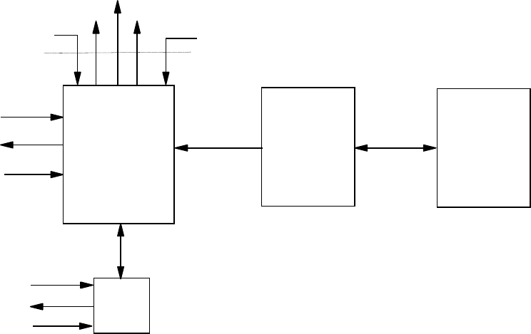
APPENDIX C: EVENT PROGRAMMING
Page 168 MRC-565 Packet Data Radio Operations & Maintenance
APPENDIX C: EVENT PROGRAMMING
The MRC-565 supports customer-programmed event logic. Discrete and analog inputs can be
monitored by the event program to detect "events" which then perform a defined "action".
Actions may include the controlling of discrete output signals, incrementing counters, setting
timers, and transmission of canned messages and issuance of various reports. This means that
customers are somewhat independent of factory reprogramming from MRC and that MRC-565
behavior can be readily modified in the field. It also means that operators now have limited
power to make the MRC-565 react to various field-programmable conditions.
The operator sets up the event program when installing the MRC-565 or during maintenance and
operation. Because the event program is implemented via operator commands, it can be entered
not only at a local maintenance console, but also via the remote command capability. The event
programs are stored within a non-volatile table in the MRC-565 battery-backed-up RAM. They
are not lost due to external power failure. When the external power is restored, they will be
enabled to respond to events again.
Programming is usually done by creating a "script file" of the required event commands, and
loading these into the MRC-565 using XTERM or any other terminal emulator software.
Several input/output lines are available directly from the processor card of the MRC-565
modems. In addition, an I/O expander card (XIO) can be optionally used which uses 3 lines to
implement a high-speed serial link for accessing the signals of the expander card.
MCC-545 Rf Modem EVENT SCRIPT
FILE TEXT EDITOR
XIO
$HT
TEXT
MESSAGES REMOTE
COMMANDS
DISCRETE
INPUTS
DISCRETE
OUTPUTS
ANALOG
INPUTS
DISCRETE
INPUTS
DISCRETE
OUTPUTS
ANALOG
INPUTS
RF LINK
SERIAL
PORT
MCLK
MDIR
MSET
POS TEXT
MSG
SDATA
APPENDIX C: EVENT PROGRAMMING
Page 169 MRC-565 Packet Data Radio Operations & Maintenance
Event Programming Overview
Event programs are composed of signal test and action commands stored in a non-volatile event
table. The MRC-565A stores the event table in battery-backed-up-RAM. The MRC-565 and
MRC-565C store the event table in FLASH memory.
The operator enters these event commands into the MRC-565. The MRC-565 scans the event
table at power-up/reset, and then at every 1/16 second clock interval. It looks for the occurrence
of defined events. When a defined event occurs, the MRC-565 invokes the corresponding action
commands. The capability includes:
Testing discrete input lines
Setting or clearing a discrete output line
Testing Analog input values
Transmitting brief text messages
Execute a local command of up to 40 characters
Transmitting vehicle position reports
Transmitting marker drop reports
Transmitting vehicle collision reports
Transmitting canned message reports.
Defining sensor data (SDATA) groups
Transmitting sensor data (SDATA) reports
Setting or clearing the MDP Status Bits
Setting or clearing and testing 5 timers
Testing GPS status as a discrete input
Testing Network status as a discrete input
Setting or clearing and testing counters
Setting or clearing and testing 2 high-speed counters
Outputting pulses and square waves (pulse modulation)
Reading and counting pulse inputs
Max, Min, Average or other real-time signal computations
The position, marker drop, collision and canned message reports created conform to the
FleetTrak standard. In addition other status bits can be set or cleared individually. Up to 16 data
report groups can be defined for SDATA formatted data report generation.
The MRC-565 event monitor reads discrete and analog inputs and evaluates them with respect to
event definitions in the event table. It can look for discrete input signals going persistently high
or low, and for analog signals persistently exceeding or under running thresholds.
APPENDIX C: EVENT PROGRAMMING
Page 170 MRC-565 Packet Data Radio Operations & Maintenance
Event definition
An "event" occurs when some input signal or timer changes its state. You can think of a state as
being "on" or "off", "1" or "0", "true" or "false". When the state changes, an "action" can then
be taken. Once the signal has changed state and the action performed, it will not take further
action until the state changes again to prevent a continuous string of actions. For example, if a
switch is turned "on", the lights come on and stay on. They don’t continually go on,on,on…
Once the switch is turned off, the lights can go off, and then they are ready to be turned on again,
etc.
There are three classes of events: Reset, Immediate and Scanned. Scanned events subdivide into
discrete I/O events and analog input events. These are defined in the following paragraphs.
Reset Event
A reset event occurs only once when the MRC-565 powered up or reset, when the event monitor
task is started for the first time, or is stopped - then restarted. It is a well-defined event that does
not need to scan anything in order to determine whether or not a reset has occurred. It occurs
once on each power up or monitor-start. There is also no corresponding end to this event. The
logical end of this event would be power failure or shutdown, but either such event makes the
MRC-565 unable to respond to anything. An action taken on a reset event command will remain
as defined in the command until the MRC-565 is reset again or powered off, or until some other
event changes the action. Stopping the event monitor will not clear the reset event definitions.
Command Event
An immediate action can be triggered by entering a local event command from any port, or by
remote command sent over the RF link. This type of action does not get stored in the event table
and will not be re-issued on power-up or restart. In this way, the operator has the ability to
manually override or control conditions in the field. The event state is considered to be "true" as
soon as the command is entered or received. Once the action is completed, the event state is set
to "false" again.
Scanned Event
Scanned events are tested on a periodic basis by the monitor task. An input signal that would
trigger a scanned event must be repeatedly tested to see if the signal persists at a trigger level
before an event is started. A scanned event is started when a signal remains at (or above or
below) the trigger level for a defined settling duration. When an event is detected by its input
condition persisting at its high state for a settling duration, that event's associated action is
triggered and the monitor task begins looking for the end of the event. The end of an event
occurs when the event remains at a low state for a defined hold-off duration. After the hold-off
duration with the input condition at its low state, the event is enabled to scan for the next event.
For example, if an event is testing the battery voltage to be above 5.0 volts, the action will be
triggered when the voltage is first detected to be at or above 5.0 volts for the entire settling
period. When the voltage goes below 5.0 volts for the hold-off period, it will re-arm the event to
APPENDIX C: EVENT PROGRAMMING
Page 171 MRC-565 Packet Data Radio Operations & Maintenance
trigger the next time the voltage goes to or above 5.0 volts. The event action is not triggered
when the voltage crosses the 5.0 level in the downward direction, only the upward direction. If
one wants to detect both voltage crossings, there should be two events defined, one to detect the
positive change (ADCHI), and one to detect the negative change (ADCLOW).
The settling and hold-off durations are programmable for each scanned event. They are specified
in clock-tick counts where each tick is 62.5 milliseconds, or 1/16 second. Because these
durations are programmable, scanned event hysteresis is fully controllable. Given the 62.5
millisecond sampling rate, events are limited to those that persist longer than 62.5 milliseconds
but shorter than about an hour duration. Similarly, hold-off times between events must also
persist longer than 62.5 milliseconds. Attempting to program events that are briefer than 62.5
milliseconds will prove unreliable. It is important to remember that a scanned event must
change slow enough that the event monitor can sample the input line reliably.
The external I/O expander (XIO) has its own processor to scan its event definition table. Its
internal "clock-tick" will be set to one millisecond per increment. The MRC-565 will configure
the XIO when event commands are processed from the script file. The XIO will monitor its own
events and send changes to the MRC-565 using a serial interface.
Discrete Event
A discrete event is determined by whether or not a discrete input signal remains either high or
low for the given settling duration. "high" or "low" is a part of the event definition set by the
operator. The end of a discrete event occurs when the signal has persistently returned to its
previous low or high state for the hold-off duration. For RS 232 signals, "high" is considered the
ON state and "low" the OFF state. "high" is also known as SET; "low" as CLR.
The high/low convention follows the voltage level of the input signal. For TTL signals, "high" is
a +5 volt level, and "low" is zero volts. For the RS-232 modem-control signals, "high" is +10
volts and "low" in -10 volts. For the GPS input, a "high" is when the GPS is at "V1" or "V2"
status, and "low" is when there is no GPS characters being received at the RS-232 port or when
the GPS is at the "V0" status. The NET input is "high" when the RF modem is online to a Base
or Repeater that is connected to a host system. The NET "low" input indicates the RF modem is
offline to a Base or Repeater.
Analog Event
An analog event is determined by whether or not an analog input signal remains above or below
a threshold for the given settling duration. "Above" or "below" and the threshold level are also
given in the event definition. The end of an analog event occurs when the signal has persistently
returned to the non-event side of the threshold for the hold-off duration.
APPENDIX C: EVENT PROGRAMMING
Page 172 MRC-565 Packet Data Radio Operations & Maintenance
Action Definition
An "action" can be assigned to each event defined in the event table. When the event condition
is detected, the action is initiated. Available actions are defined in the following sections.
Multiple actions are supported by defining multiple events that test the same input, but take
different action, or multiple actions can be defined using a special "continue" event. The
“continue” event does not test the input condition again, but will trigger the action when the
event it is connected to detects the event.
Any action can be forced on a timed basis by several methods. One method is to use the MRC-
565 scheduler (SCHED command) to trigger the desired immediate action. For example, the
UPDT action can be specified by the insertion of the EVENT,UPDT, group-number command
into the MRC-565 scheduler to produce reports on a timed basis. See the SCHED command for
this capability. Another example would be to pulse an output line by placing two commands in
the scheduled event list that would first SET then CLR the signal. The duration of the pulse
would be controlled by the offset value in the SCHED command. Yet another method is to use
an event timer (counter) to facilitate scheduling of actions. Special timer registers are provided
for this purpose, and will automatically count down from a non-zero value to zero at a rate of
1/16 seconds per count. An event command can monitor the timer register, and when it reaches
zero, the action can be taken, and the timer reset to the next desired time count.
Programming in Real-Time
Events are programmed via operator commands, one event per command line. It is a multi-step
process. Because of this, each event being entered will be a fragment until all event definitions
are complete. If the event monitor is allowed to execute a fragment of an event, strange and
possibly adverse actions will occur. Therefore, the operator should stop the event monitor when
adding events and actions to the event table. The event monitor task can be stopped and started
by operator command. The best way to do this is to use a script file containing the stop
command, a command to delete all prior definitions, the desired event definitions, and a start
command.
Some examples are given below, following these, a detailed description of each event command
and action is given.

APPENDIX C: EVENT PROGRAMMING
Page 173 MRC-565 Packet Data Radio Operations & Maintenance
Example 1: A Scanned Event - Vehicle Tip-Over Detection
Suppose the MRC-565 is wired to detect a vehicle tip-over using the CTS and DTR signals and a
gravity switch that closes if it does not remain mostly upright. The CTS output is used to enable
tip-over detection. The DTR input is the signal on which tip-over event is detected. Normally
open, the switch prevents DTR from receiving the CTS signal. If CTS is enabled and the vehicle
tips over such that the switch closes, the CTS signal is presented to DTR.
To make the tip-over detection mechanism function, the CTS signal must be enabled so that it
can be detected at DTR should the switch close. A good time to enable CTS – set CTS to high –
may be when the MRC-565 is powered up. The command EVENT,RESET,SET,CTS will do
this. The event is RESET. The action is SET,CTS. The "ignition" bit should also be set in the
status word. The bits of the status register are numbered from low order to high order, BIT0
through BIT15. The COLLISION bit is the same as BIT0, and the action "COLLISION" is used
instead of "SET,BIT0" for clarity.
The command EVENT,DIOHI,DTR,16,160,COLLISION defines an event that creates a
vehicle collision report if the DTR signal is high for 1 second (16 sixteenths of a second).
Collision is defined as the vehicle being tipped over. The event will clear and be ready for
another event if the signal is low for 10 seconds (160 sixteenths of a second). "DIOHI" means
"discrete I/O high" and "DTR" specifies the DTR discrete input. The parameters
"DIOHI,DTR,16,160" define the event. The parameter "COLLISION" defines the action.
The User will create the event table with the following commands:
MCC-545 RF Modem
CTS
DTR
Gravity
Switch
CTS is set to 5V on power-up, DTR is low if switch is open
DTR will go high when the switch is closed
EVENT,STOP
EVENT,DEL,ALL
EVENT,RESET,SET,CTS
EVENT,RESET,SET,BIT2
EVENT,DIOHI,DTR,16,160,COLLISION
EVENT,START
SAVE

APPENDIX C: EVENT PROGRAMMING
Page 174 MRC-565 Packet Data Radio Operations & Maintenance
Example 2: A Scanned Event - Marker-Drop
Suppose the MRC-565 is wired to detect a marker-drop pushbutton using the CTS and DTR
signals wired to a pushbutton switch mounted somewhere in a vehicle or aircraft. The CTS
output is used to enable switch detection. The DTR input is the input signal on which marker-
drop is detected. Normally open, the switch prevents DTR from receiving the CTS signal. If CTS
is enabled and the marker-drop button pressed such that the switch closes, the CTS signal is
presented to DTR.
To make the marker-drop mechanism function, the CTS signal must be enabled so that it can be
detected at DTR should the switch close. A good time to enable CTS – set CTS to high – may be
when the MRC-565 is powered up. The command EVENT,RESET,SET,CTS will do this. The
event is RESET. The action is SET,CTS. The "ignition" bit should also be set in the status
word, the command EVENT,RESET,SET,BIT2 will set the ignition bit. The bits of the status
register are numbered from low order to high order, BIT0 through BIT15. The MARK bit is the
same as BIT3, and the action "MARK" is used instead of "SET,BIT3" for clarity.
The command EVENT,DIOHI,DTR,16,160,MARK defines an event that creates a vehicle
collision report if the DTR signal is high for 1 second (16 sixteenths of a second). The event will
clear and be ready for another event if the signal is low for 10 seconds (160 sixteenths of a
second). "DIOHI" means "discrete I/O high" and "DTR" specifies the DTR discrete input. The
parameters "DIOHI,DTR,16,160" define the event. The parameter "MARK" defines the
action.
MCC-545 RF Modem
CTS
DTR
Marker-Drop
Switch
CTS is set on reset in order to have a signal to detect on DTR
DTR is scanned every 1/16 second for the high condition

APPENDIX C: EVENT PROGRAMMING
Page 175 MRC-565 Packet Data Radio Operations & Maintenance
The User will create the event table with the following commands:
Event Programming Command Summary
There can be from 1 to 400 events defined in the event table including reset and scanned events.
The following list shows all the command formats. Commands tagged "Yes" in the "Event"
column each consume one entry in the event table. Some of the commands, tagged with "No",
are used to free up event table entries or control the operation of the event monitor.
There is also a group table, and a text table. The group table an array of 16 groups by 16 sensors.
Each entry in the group table consists of a sensor type – discrete or analog – and a discrete bit
identification or analog channel number. Commands tagged "Yes" in the "Group" column each
consume one entry in the group table. Some of the commands with "Yes" are used to free up
group table entries. The text table is used to store up to 40 text messages or operator commands
of up to 40 characters each.
There are 8 accumulators, 8 timers and 8 counters that can be used to facilitate the creation of
complex logic.
Table Entry?
Command
Event
Group
EVENT
No
No
EVENT, DEL, event number
No
No
EVENT, DEL, ALL
No
No
EVENT, START
No
No
EVENT, STOP
No
No
EVENT, RESET, action
Yes
No
EVENT, DIOHI, bit-name, settle, holdoff, action
Yes
No
EVENT, DIOLOW, bit-name, settle, holdoff, action
Yes
No
EVENT, ADCHI, chan-name, hi-level, settle, holdoff, action
Yes
No
EVENT, ADCLOW, chan-name, low-level, settle, holdoff, action
Yes
No
EVENT, IFGT, bit-name, bit-name, action
Yes
No
EVENT, IFLT, bit-name, bit-name, action
Yes
No
EVENT, IFEQ, bit-name, bit-name, action
Yes
No
EVENT, CONT, action
Yes
No
EVENT, DO, action
Yes
No
EVENT,STOP
EVENT,DEL,ALL
EVENT,RESET,SET,CTS
EVENT,RESET,SET,BIT
2
EVENT,DIOHI,DTR,16,
160,MARK
EVENT,START
SAVE

APPENDIX C: EVENT PROGRAMMING
Page 176 MRC-565 Packet Data Radio Operations & Maintenance
EVENT, DISPLAY, item-number
Yes
No
EVENT, TEXT
No
No
EVENT, TEXT, item-number, message text
Yes
Yes
EVENT, TEXT, DEL, ALL
No
No
EVENT, TEXT, DEL, item-number
No
No
EVENT, GROUP
No
No
EVENT, GROUP, group-number, bit-name or chan-name, …
No
Yes
EVENT, GROUP, DEL, ALL
No
Yes
EVENT, GROUP, CLEAR, group-number
No
Yes
EVENT, UPDT, group-number
No
No
EVENT, STATUS, {bit-name, chan-name}
No
No
EVENT, action
No
No
SCALE, chan-name, slope, offset
No
No
Event Programming Command Details
Commands
EVENT
Displays the current event and group table when no additional parameters are attached. All the
event commands begin with "event," followed by parameters.
EVENT, DEL, ALL
Delete all events in the event table. Event table commands should be edited in script files and
output to the MRC-565 using XTERM in order to reload the event table. This command does not
delete the text messages or group definitions.
EVENT, DEL, number
Delete only the numbered event from the event table. The events will be renumbered when one is
deleted. Event table commands should be edited in script files and output to the MRC-565 using
XTERM in order to reload the event table.
EVENT, START
Start the event scanner. Scanned events will not be detected unless scanning is started. This
command causes the event scanner to review the event table every 62.5 milliseconds for the
occurrence of scanned events and the end of scanned events. This command also performs
RESET events. On MRC-565 reset, the event scanner is started.
EVENT, STOP
Stop the event scanner. Scanned events will not be detected while scanning is stopped. This
command should be issued prior to clearing the event table (EVENT,DEL,ALL) and
reprogramming it with events. This command does not affect the detection of the reset event. On

APPENDIX C: EVENT PROGRAMMING
Page 177 MRC-565 Packet Data Radio Operations & Maintenance
MRC-565 reset, the event scanner is started again if the SAVE command was not issued while in
the EVENT,STOP state.
EVENT, action
A direct command for immediate action can be issued. This event command will not be added to
the event table, but will cause the action to occur when the command is entered. This can be
used to take action using remote commands, and also can be placed in the MRC-565 schedule
list for periodic event application.
EVENT, STATUS, {bit-name, or chan-name}
This form of the command lets the operator display an immediate value for any discrete input bit
or any ADC channel. For example: to display the status on the DTR input line,
EVENT,STATUS,DTR<cr>. To display forward power, enter EVENT,STATUS,FPWR<cr>.
EVENT, RESET, action
Define an action to be taken at power-up/reset. This is useful for setting control outputs at a
known state or sending a message to a host system that the MRC-565 has been reset. These
RESET actions will also occur if the event monitor is stopped, then restarted. This allows
entering new RESET events into an existing table.
EVENT, DIOHI, bit-name, settle, holdoff, action
Define an event that looks for a discrete input line to go to a high level.
Parameter
Description
DIOHI
Scan discrete input signal for high condition.
bit-name
Name of discrete input signal to be scanned for high level. (single or multiple
inputs)
settle
Number of clock ticks for the input signal to settle at the high level before
declaring an event
holdoff
Number of clock ticks for the analog input signal to settle at the low level to be armed
for detecting the next event.
action
MRC-565 action to be taken when event is declared. See actions below.
Logical combining of multiple discrete inputs is allowed. This is done by expanding the bit-
name parameter of the command into a list on inputs separated by logic operator characters. For
example, to test both the RTS and DTR inputs in one event, use the string ",DTR & RTS," in the
bit-name parameter. Up to 5 inputs can be used in a single event line. Any of the inputs can be
"inverted" before the combination. For example, if the DTR input must be high and the RTS
input low to trigger an event, use the string ",DTR & !RTS," in the bit-name parameter.
The inputs can be combined in any order. The evaluation is done from left to right. There is no
use of "(" and ")" to form more complex ordering. The "0" and "1" values are used for "low" and

APPENDIX C: EVENT PROGRAMMING
Page 178 MRC-565 Packet Data Radio Operations & Maintenance
"high". If the result of the combination of signals is "1", then the DIOHI condition is satisfied. If
the result of the combination is "0", then the DIOLOW condition is satisfied.
Both the DIOHI and DIOLOW event types can use the logical signal support.
Table of Logical Operators: Operator Definition
& AND
| OR
! NOT Logical signal inversion
EVENT, DIOLOW, bit-name, settle, holdoff, action
Define an event that looks for a discrete input line to go to a low level.
Parameter
Description
DIOLOW
Scan discrete input signal for low condition.
bit-name
Name of discrete input signal to be scanned for low level. (single or multiple
inputs)
settle
Number of clock ticks for the input signal to settle at the low level before
declaring an event.
holdoff
Number of clock ticks for the analog input signal to settle at the high level to be
armed for detecting the next event.
action
MRC-565 action to be taken when event is declared. See actions below.
EVENT, IFGT, bit-name1, bit-name2, action
Test whether a timer, counter or accumulator is greater than another timer, counter or
accumulator.
Parameter
Description
IFGT
If first parameter is greater than second parameter.
bit-name1
Name of a timer, counter or accumulator to test.
bit-name2
Name of a timer, counter or accumulator to test bit-name1 against.
action
MRC-565 action to be taken when event is declared. See actions below.
EVENT, IFLT, bit-name1, bit-name2, action
Test whether a timer, counter or accumulator is less than another timer, counter or accumulator.
Parameter
Description
IFGT
If first parameter is less than second parameter.
bit-name1
Name of a timer, counter or accumulator to test.
bit-name2
Name of a timer, counter or accumulator to test bit-name1 against.
action
MRC-565 action to be taken when event is declared. See actions below.
EVENT, IFEQ, bit-name1, bit-name2, action
Test whether a timer, counter or accumulator is equal to another timer, counter or accumulator.

APPENDIX C: EVENT PROGRAMMING
Page 179 MRC-565 Packet Data Radio Operations & Maintenance
Parameter
Description
IFEQ
If first parameter is equal to second parameter.
bit-name1
Name of a timer, counter or accumulator to test.
bit-name2
Name of a timer, counter or accumulator to test bit-name1 against.
action
MRC-565 action to be taken when event is declared. See actions below.
EVENT, CONT, action
The CONT (Continue) event is used to define multiple actions to an event. An event definition
command can be followed by any number of CONT commands and are considered to be an
extension of the previous event command. For example:
EVENT,DIOHI,DTR,1,1,SET,BIT0 ;Defines an event with one action
EVENT,CONT,TXT,1 ;Add another action
EVENT,CONT,UPDT,1 ;Add another action
EVENT,CONT,CLR,T1 ;Add another action
EVENT,DIOLOW,DTR,1,1,CLR,BIT0 ;End previous event definition, Start next one
EVENT, DO, action
The DO event is provided for cases where an unconditional action is required. This type of event
is not connected to other event lines as the CONT is. It is independent and will be initiated every
time the event monitor executes the script item. For example: EVENT,DO,INC,C1
EVENT, ADCHI, chan-name, hi-level, settle, holdoff, action
Define an event that looks for an analog input signal to go at or above a high level.
Parameter
Description
ADCHI
Scan A-to-D converter channel (analog input signal) for high condition.
Chan-name
Name of analog input signal to be scanned for high condition. (single input
only)
hi-level
Signal level for the event to trigger at or above which the analog input signal must
persist in order for an event to be declared. Scaled in Engineering Units.
settle
Number of clock ticks for the input signal to settle at or above the trigger level
before declaring an event.
holdoff
Number of clock ticks for the input signal to settle below the trigger level to be armed
for detecting the next event.
action
MRC-565 action to be taken when event is declared. See actions below
EVENT, ADCLOW, chan-name, low-level, settle, holdoff, action

APPENDIX C: EVENT PROGRAMMING
Page 180 MRC-565 Packet Data Radio Operations & Maintenance
Define an event that looks for an analog input signal to go at or below a low level.
Parameter
Description
ADCLOW
Scan A-to-D converter channel (analog input signal) for low condition.
Chan-name
Name of analog input signal to be scanned for low condition. . (single input
only)
low-level
Signal level for the event to trigger at or below which the analog input signal must
persist in order for an event to be declared. Scaled in Engineering Units.
settle
Number of clock ticks for the input signal to settle at or below the trigger level
before declaring an event.
holdoff
Number of clock ticks for the input signal to settle above the trigger level to be
armed for detecting the next event.
action
MRC-565 action to be taken when event is declared. See actions below.
EVENT, TEXT, item-number, message or command text
Add a new text string into the text table. This command will replace an existing item if one
already exists with the same item number.
Parameter
Description
TEXT
Define a Text string command.
item-
number
Item number to be created or replaced by this command. Valid range: 1
through 40.
message
text
Body of the text. Can be up to 40 characters, and will be converted to upper case.
The text is used by the TXT or CMD action to send a text message or issue a local
command.
EVENT, TEXT
Displays the current text table.
EVENT, TEXT, DEL, ALL
Deletes all Previously defined text items.
EVENT, TEXT, DEL, item-number
Deletes a specific item from the text table. This command makes the given item be a null
message. The other text string items in the table are not affected.
EVENT, GROUP
Displays the group table. There can be as many as 16 groups defined, where each group consists
of a selected set of analog inputs or discrete inputs. The "event, group" set of commands allows
the groups to be defined, displayed, and transmitted as a sensor data report.

APPENDIX C: EVENT PROGRAMMING
Page 181 MRC-565 Packet Data Radio Operations & Maintenance
The Group Table layout is like a two dimensional array where each row is a different group, and
each column is a different sensor. In this case a sensor can be either an analog or discrete input.
Type indicates discrete or analog. For discrete, Id is the bit number. For analog, Id is the
channel number.
Sensor Number
1
2
3
● ● ●
16
Group Number
1
Type/Id
Type/Id
Type/Id
Type/Id
2
Type/Id
Type/Id
Type/Id
Type/Id
3
Type/Id
Type/Id
Type/Id
Type/Id
●
●
●
16
Type/Id
Type/Id
Type/Id
Type/Id
EVENT, GROUP, group-number, bit-name or chan-name, …
Define an event sensor data (SDATA) report group.
Parameter
Description
GROUP
Group control event command.
group-
number
Group number to be set by this command. Valid range: 1 through 16.
bit-name or
chan-name
List of up to 16 discrete and/or analog input signal names to be included in the
group. The values of these signals form the contents of a sensor data (SDATA)
report. They are reported in the order specified in this command. Append a “/F” to
any name for floating point scaling. Append “(x.xx)” for decimal scaling as:
ADC1/F(0.1)
Example: EVENT, GROUP, 1, FPWR/F, ADC1, ADC2/F(1.123)
EVENT, GROUP, DEL, ALL
Delete all group definitions. Clears the group table.
EVENT, GROUP, DEL, group-number
Delete a specific group definition from the group table. This does NOT cause the other defined
groups to be renumbered.
Parameter
Description
GROUP
Group control event command.
DEL
Delete group table sub-command.
group-
number
Group number to be deleted by this command. Valid range: 1 through 16.

APPENDIX C: EVENT PROGRAMMING
Page 182 MRC-565 Packet Data Radio Operations & Maintenance
EVENT,UPDT, group-number
Produce an immediate SDATA group report when the command is entered.
Parameter
Description
UPDT
Update sub-command; i.e., issue a group sensor data (SDATA) report.
group-
number
Group number to be reported in an SDATA report. Valid range: 1 through
16.
This command can be included in the MRC-565 schedule to produce reports on a periodic or
prescribed time of day. For example, "SCHED,I,10:0,EVENT,UPDT,3" will schedule the
group 3 sensor data report every 10 minutes.
SCALE, chan-name, slope {, offset}
Enter engineering units scale factor and offset for an analog channel. This adds the optional
offset parameter to the original MRC-565 SCALE command. Analog event detection is based on
scaled values, not raw counts. The scaled value is computed as:
scaled value = (analog channel raw count * slope) + offset
Parameter
Description
chan-name
Name of analog input channel to be scaled by the factors provided in this
command.
slope
Multiplier scaling factor. The analog input channel raw count is multiplied by
this value. Valid: any decimal floating point number that can be represented
in Motorola 68000 32-bit floating point format. However, there is a further
restriction on the value of slope. See below.
offset
Bias scaling factor. This value is added to the product of the channel raw
count and the multiplier scaling factor. Optional parameter. Assumes zero
offset when not given. Valid: any decimal floating point number that can be
represented in Motorola 68000 32-bit floating point format. However, there
is a further restriction on the value of slope. See below.
Slope and offset values must be chosen such that the resultant scaled value is in the range -
8192.0 through -0.001, 0.000 and +0.001 through +8191.0. Only four digits of the scaled value
are significant.

APPENDIX C: EVENT PROGRAMMING
Page 183 MRC-565 Packet Data Radio Operations & Maintenance
Action Definitions
The following table shows the possible types of action that can be taken when an event occurs.
Action Value
Action Parameters
Description
TXT, nn
text table item number
Transmit a text message to the default destinations.
NN can range from 1 to 40.
CMD, nn
text table item number
Execute a local command. NN can range from 1 to
40.
CAN, nn
Canned message number
The canned message number is transmitted to 1 to 4
default destination IDs. Valid range: 0 to 255.
POS
A position report with current GPS coordinates is
transmitted to 1 to 4 default destination IDs.
MARK
A marker report with current GPS coordinates is
transmitted to 1 to 4 default destination IDs. The
marker bit is set in one report, but does not remain
set.
COLLISION
A vehicle collision report is transmitted to 1 to 4
default destination IDs. The collision bit is set in one
report, but does not remain set.
SET, ccc, ddd
ccc=Bit, Timer, Counter,
Accumulator Name
ddd=optional decimal value
for Timer, Counter or
Accumulator
If ccc is a named discrete output or status bit, it is
set = 1 and ddd is not used. If ccc is a Timer,
Counter or Accumulator, then ddd is a decimal value
to put into ccc. If ccc is a status bit, a POSS report
will be transmitted with the updated status bits. The
bit remains set.
SET/N, ccc
ccc = status bit name
Sets the status bit and does NOT transmit POSS
SET/T, ccc
ccc = status bit name
"Trigger" a POSS report after setting the status bit,
but clear the bit after the transmission so it is a one-
time event and does not persist.
CLR, ccc
ccc=Bit, Timer, Counter,
Accumulator Name
The named discrete output, status bit, Timer,
Counter or Accumulator is cleared to 0. If ccc is a
status bit, a POSS report will be transmitted with the
updated status bits. The bit remains cleared.
CLR/N,ccc
ccc = status bit name
Clears the status bit and does NOT transmit POSS
PULSE,bit-
name, ddd,
iii, nnn
bit-name is any discrete
output signal
Produce a pulse or series of pulses on the output line
where: ddd is the pulse duration in clock ticks, iii is
the interval between pulses in clock ticks and nnn is
the number of pulses to output.
ADCIN, ccc,
aaa, mult
ccc=any ADC channel name
aaa=accumulator name A1 –
A24
mult=decimal scaling
multiplier
Read the ADC channel value and store in it the given
accumulator. The value is scaled, multiplied by the
optional multiplier, then converted from floating
point to a long 32-bit integer. The value of 10.123
with a multiplier of 10 will be stored as 103.
UPDT, group-
number
SDATA report group
number
The SDATA report specified by the group number is
transmitted to 1 to 4 default destination ids.
NC, ccc
+1
Increment a counter by 1. Where ccc must be a valid
counter (C1-C8)
DEC, ccc
-1
Decrement a counter by 1. Where ccc must be a valid
counter (C1-C8)

APPENDIX C: EVENT PROGRAMMING
Page 184 MRC-565 Packet Data Radio Operations & Maintenance
ADD, ccc,
ddd
Add the decimal value of ddd to ccc. Where ccc must
be a valid accumulator (A1-A24) . The result is
stored in ccc.
SUB, ccc,
ddd
Subtract the decimal value of ddd from ccc. Where
ccc must be a valid accumulator (A1-A24) . The
result is stored in ccc.
MUL, ccc,
ddd
Multiply ccc by the decimal value of ddd and place
the result in ccc. Where ccc must be a valid
accumulator (A1-A24).
DIV, ccc,
ddd
Divide ccc by the decimal value of ddd and place the
result in ccc. Where ccc accumulator (A1-A24).
MOV, ddd,
sss
Move the source sss into ddd where sss and ddd are
valid Timers (T1-T8) , Counters (C1-C8) or
Accumulators (A1-A24)
ADDA, ccc,
aaa
Add the accumulator value of aaa to ccc. Where aaa
and ccc must be a valid accumulator (A1-A24) . The
result is stored in ccc.
SUBA, ccc,
aaa
Subtract the accumulator value of aaa from ccc.
Where aaa and ccc must be a valid accumulator (A1-
A24) . The result is stored in ccc.
MULA, ccc,
aaa
Multiply ccc by the accumulator value of aaa and
place the result in ccc. Where aaa and ccc must be a
valid accumulator (A1-A24).
DIVA, ccc,
aaa
Divide ccc by the accumulator value of aaa and place
the result in ccc. Where aaa and ccc accumulator
(A1-A24).
The default destination IDs for messages created by the actions above are set via the DESTINATION, d1
{, d2 {, d3 {, d4}}} command. When a single ID of “0” is given in a Meteor Burst Network that uses the
MRC-520B for a Master Station, the messages are sent to the network host system for routing via the
source routing system. In a Line-of-Sight network, using MRC-565’s as Base and/or Repeater Stations,
then a single ID of “1” is used for routing to the Host via any Base or Repeater.
Common Command Parameters
Settle
settle is the number of clock ticks required "at or above" the event level to trigger an event.
Valid range: 1 - 65535. This corresponds to a range of 62.5 milliseconds to 1 hour, 8 minutes
and 16 seconds. For discrete events, the event level is "high" or "1". For analog events, the
level is given in engineering units.
Holdoff
holdoff is the number of clock ticks required "below" the event level to allow another event.
Valid range: 1 - 65535. This corresponds to a range of 62.5 milliseconds to 1 hour, 8 minutes
and 16 seconds.

APPENDIX C: EVENT PROGRAMMING
Page 185 MRC-565 Packet Data Radio Operations & Maintenance
Bit-name
Bit Name
I/O; Voltage Range
Definition
Description
BIT0-
BIT15
Status Register Bits
0 or 1
The bit names BIT0, BIT1, …through BIT15
correspond to the bits of the 16-bit status register.
BIT0 is the low order bit, BIT15 is the high order bit.
DTR
Input; TTL 0V to 5V
Data
Terminal
Ready
RS 232 serial port signal indicating the data terminal
connected to the serial port is ready and able to
receive data from the MRC-565 (dataset) on Rx Data.
RTS
Input; RS 232 ±10V
Request to
Send
RS 232 serial port signal indicating the data terminal
connected to the serial port wants to transmit data to
the MRC-565 (dataset) on Tx Data.
CTS
Output; TTL 0V to 5V
Clear to
Send
RS 232 serial port signal indicating the MRC-565
(dataset) is ready and able to receive data from the
data terminal connected to the serial port on Tx Data.
RING
Output; RS 232 ±10V
Ring
Detected
RS 232 serial port signal indicating the MRC-565
(dataset) is wants the attention of the data terminal
connected to the serial port.
MCLK
Output; TTL 0V to 5V
Clock
These three signals can be used as individual inputs
and outputs as noted. In addition they can be used to
communicate with the external I/O expander using a
clocked serial high speed data stream.
MDIR
Output; TTL 0V to 5V
Data In
MSET
Input; TTL 0V to 5V
Data Out
IN1,IN2
IN3,IN4
Optically Isolated
Inputs 0-5 Volts
0 or 1
Typically requires an input greater than 1 volt to
trigger an input transition from 0 to 1.
RO1,RO2
Relay Contacts
NO,NC
Provides NO,COM,NC contacts
GPS
GPS status
0 or 1
Current GPS receiver status and RS-232 port
condition. 0=V0 or RS-232 disconnected. 1=V1 or
V2 and RS-232 connected.
NET
Network Status
0 or 1
Network online/offline status. 0=offline , 1=online
T1 – T8
32-bit Timers can be
used both as an Input
and as an Output.
Timers range from 0
to 16,777,216 counts.
(12 days, 2 hrs, 18
min, 58.5 seconds)
0 or n
Timer registers. When these are set to a non-zero
value, they will count down one count for each 1/16
second (62.5 milliseconds).
Use action = SET, T1, nnnn to start counting. These
all are set=0 on reset. Power fail/restart will retain the
count at power fail.
C1 – C8
32-bit Counters can be
used both as an input
and as an output.
Counters can range
from 0 to 16,777,216
counts.
0 or n
Counter registers. These can be set to a value, cleared
to zero, incremented or decremented. A 0 decrements
to 16,777,216. A 16,777,216 increments to 0.
A1-A24
32-bit Accumulators
can be used both as an
input and as an output.
Value can range from
0 to +/-16,777,216
0 or n
General purpose accumulators. These are used for
computational or temporary storage of numerical
values.
Each of the bit-names in the above table can be used in Event and Action definitions. The
DIOHI/DIOLOW events can use DTR, RTS, IN1-4, GPS, NET, T1-T8, C1-C8, A1-A24 as inputs. The

APPENDIX C: EVENT PROGRAMMING
Page 186 MRC-565 Packet Data Radio Operations & Maintenance
Action parameter can use BIT0-BIT15, CTS, RING, MCLK, MDIR, MSET, RO1-R02, T1-T8, C1-C8,
A1-A24 as outputs.
Examples:
EVENT,DIOHI,IN1,16,16,SET,RO1 Waits for input line 1 to go high for 1 second, then sets RO1 to
NC.
EVENT,DIOLOW,DTR,16,16,SET,T1,160 Waits for DTR to go high for 1 second, then starts
timer-1 at 160 counts (10 seconds).
EVENT,DIOLOW,T1,1,1,TXT,1 Waits for timer-1 to go to zero, then sends a text message
indicating that DTR timed-out.
ADC Channel Names
Channel Name
Definition
Description
FPWR
Forward RF power
RF power going out of the MRC-565 transmitter.
RPWR
Reverse RF power
RF power being reflected back to the MRC-565 transmitter.
LBAT
Battery level
Voltage level of the MRC-565 battery.
DETRF
Detected RF
Current MRC-565 receiver detected RF level.
TEMP
Internal temperature
Internal temperature of the MRC-565 enclosure.
TXC
Transmit Count
Total number of transmissions
ACK
Acknowledge Count
Total number of acknowledgements
RXC
Received Segments
Total number of received text message segments, position
reports and data reports
PROBE
Idle Probe Count
Total number of Idle probes and poll frames received
REMOTE
Number of Remotes
Number of remotes connected to this unit.
ADC1
Analog Input
Available MRC-565/C 10-bit A-to-D channel.
ADC2
Analog Input
Available MRC-565/C 10-bit A-to-D channel.
ADC3
Analog Input
Available MRC-565/C 10-bit A-to-D channel.
ADC4
Analog Input
Available MRC-565C/ 10-bit A-to-D channel.
ADC5
Analog Input
Available MRC-565/C 10-bit A-to-D channel.
ADC6
Analog Input
Available MRC-565/C 10-bit A-to-D channel.
Event Programming Examples
Example 1: Vehicle Collision Detection
From the example above, the following is the script for initializing the MRC-565 for the
detection of vehicle tip-over.
EVENT,STOP
EVENT,DEL,ALL
EVENT,RESET,SET,CTS
EVENT,DIOHI,DTR,16,160,COLLISION
.
. other MRC-565 initialization commands

APPENDIX C: EVENT PROGRAMMING
Page 187 MRC-565 Packet Data Radio Operations & Maintenance
.
EVENT,START
Example 2: MRC-565 Reset Notification
Suppose a system that requires notification if the MRC-565 resets. The following is the script for
initializing the MRC-565 for the detection and reporting of MRC-565 reset using a text message.
EVENT,STOP
EVENT,DEL,ALL
EVENT,TEXT,1,Dead River RF Modem Reset
EVENT,RESET,TXT,1
.
. other MRC-565 initialization commands
.
EVENT,START
The following is the script for initializing the MRC-565 for the detection and reporting of MRC-
565 reset using a canned message number 1.
EVENT,STOP
EVENT,DEL,ALL
EVENT,RESET,CAN,001
.
. other MRC-565 initialization commands
.
EVENT,START
Example 3: MRC-565 High Temperature Notification
Suppose a system that requires notification of the MRC-565 enclosure becoming excessively
warm. The following is the script for initializing the MRC-565 for the detection and notification
of high temperature using canned message number 2. This example assumes the temperature
sensor and A/D converter are calibrated to produce a raw count range of 0 to 1023 that
corresponds to a Celsius temperature range of -64 degrees to +192 degrees. The SCALE
command provides the engineering units conversion factors for this. The event occurs when the
temperature A/D channel is at 50 degrees C or above for one minute or more (960 ticks). The
event ends when the temperature drops below 50 degrees C for 10 minutes (9600 ticks).
EVENT,STOP

APPENDIX C: EVENT PROGRAMMING
Page 188 MRC-565 Packet Data Radio Operations & Maintenance
EVENT,DEL,ALL
SCALE,TEMP,0.25,-64.0
EVENT,ADCHI,TEMP,50.0,960,9600,CAN,002
.
. other MRC-565 initialization commands
.
EVENT,START
Example 4: MRC-565 Low Temperature Notification
Suppose a system that requires notification of the MRC-565 enclosure becoming excessively
cold. The following is the script for initializing the MRC-565 for the detection and notification of
low temperature using canned message number 3. This example the same temperature scaling as
the previous example. The event occurs when the temperature A/D channel is at -30 degrees C or
below for one minute or more (960 ticks). The event ends when the temperature goes above -30
degrees C for 10 minutes (9600 ticks).
EVENT,STOP
EVENT,DEL,ALL
SCALE,TEMP,0.25,-64.0
EVENT,ADCLOW,TEMP,-30.0,960,9600,CAN,003
.
. other MRC-565 initialization commands
.
EVENT,START
Example 5: MRC-565 Temperature Control
Suppose a system that requires thermostatic-like control of the MRC-565 enclosure when it
becomes excessively warm or cold. The following is the script for initializing the MRC-565 for
the detection and correction of temperature out-of-bounds conditions. This example uses the
same temperature scaling as the previous two examples. The same temperature thresholds are
used. Instead of sending canned messages, it uses relay closures to turn a heat pump on and off
as needed to heat and cool the equipment room as needed. Relay closure RO5 is used to turn the
heat pump on and off in cooling mode. Relay closure RO6 is used to turn the heat pump on and
off in heating mode. RTS is used to detect heat pump failure. If the heat pump fails indicated by
RTS going low for 5 seconds, canned message 4 is transmitted.

APPENDIX C: EVENT PROGRAMMING
Page 189 MRC-565 Packet Data Radio Operations & Maintenance
EVENT,STOP
EVENT,DEL,ALL
SCALE,TEMP,0.25,-64.0
EVENT,ADCHI,TEMP,26.0,960,960,SET,RO5
EVENT,ADCLOW,TEMP,25.0,960,960,CLR,RO5
EVENT,ADCLOW,TEMP,5.0,960,960,SET,RO6
EVENT,DIOHI,TEMP,10.0,960,960,CLR,RO6
EVENT,DIOLOW,RTS,CAN,80,960,CAN,004
.
. other MRC-565 initialization commands
.
EVENT,START
Example 6: Marker Drop Button
The following is the script for initializing the MRC-565 for the detection of a vehicle operator
pressing a "drop marker" button wired into the RTS signal to go high when the button is
depressed. A MARK message is transmitted if the operator depresses the button for at least a
quarter of a second (4). The operator must release the button for three seconds (48) before
another button press will be detected.
EVENT,STOP
EVENT,DEL,ALL
EVENT,DIOHI,RTS,4,48,MARK
.
. other MRC-565 initialization commands
.
EVENT,START
Example 7: Max/Min/Averaging A/D channel values
Calculations can be performed on ADC channel values to compute averages, maximums,
minimums, etc. This is accomplished using the ADCIN action to read a value into an
accumulator, then doing math operations as desired. The following example shows a way to
average the forward power value. Many other calculations are possible. Every 5 seconds the
FPWR channel is read into accumulator 9. This value is then added to accumulator 10 to sum
the readings. Every minute the sum is divided by the number of samples to compute the average.
Notice that the ADCIN command uses a multiplier of 10 when inputting the value into
accumulator 9. Since the accumulator is an integer, this multiplier lets one decimal fraction digit
be included in the sum. The value of 100.6 Watts would be read in as 100.6, multiplied by 10 to

APPENDIX C: EVENT PROGRAMMING
Page 190 MRC-565 Packet Data Radio Operations & Maintenance
get 1006. Later, when the sum is put into the SDATA report, the FPWR/F(0.1) group/sensor
definition converts the average value back to floating point and scales the value back to Watts
with one decimal fraction digit.
MRC-565 I/O Signals
The discrete I/O lines provide digital inputs that can be read (sensed) by the event software.
MRC-565 has 3 discrete input lines, 4 discrete output lines and 4 internal analog inputs. One
input senses a 0 to 5 Volt CPU input pin and the other senses a modem control RS 232 ±10V
input line (RTS). The MRC-565 has 7 discrete input lines, 6 discrete output lines, 5 internal
analog inputs and 6 external analog inputs.
;EVENT ACTION COMMENTS
event,stop ;stop event monitor
event,del,all ;delete prev table
;
event,reset, clr, a9 ;clear current reading
event,reset, clr, a10 ;clear total
event,reset, clr, a11 ;clear max
event,reset, set, a12, 9999 ;init min to a big value
event,reset, clr, c1 ;clear sample counter
event,reset, set, c2, 12 ;set number of samples
;
event,diolow,t1,1,1,set, t1, 80 ;if t1 is zero, set t1 to 80(5
secs)
event,cont, adcin, fpwr, a9, 10 ;also read fwdpwr into reg A9
event,cont, adda, a10, a9 ; add A9 to total A10
event,cont, inc, c1 ; increment sample counter
;
event,ifgt,a9,a11, mov, a11, a9 ;get new max value
;
event,iflt,a9,a12, mov, a12, a9 ;get new minimum value
;
event,ifeq,c1,c2, diva, a10, c2 ;if C1 == C2 compute average
event,cont, updt, 1 ;then trigger group 1 SDATA report
event,cont, clr, a10 ; clear the total
event,cont, clr, c1 ; clear the sample counter
event,cont, clr, a11 ; clear the max value
event,cont, set, a12, 9999 ; init min to big value
;
;Define the SDATA group contents
; Max Min Average
event,group,1, a11/f(.1), a12/f(.1), a10/f(.1)
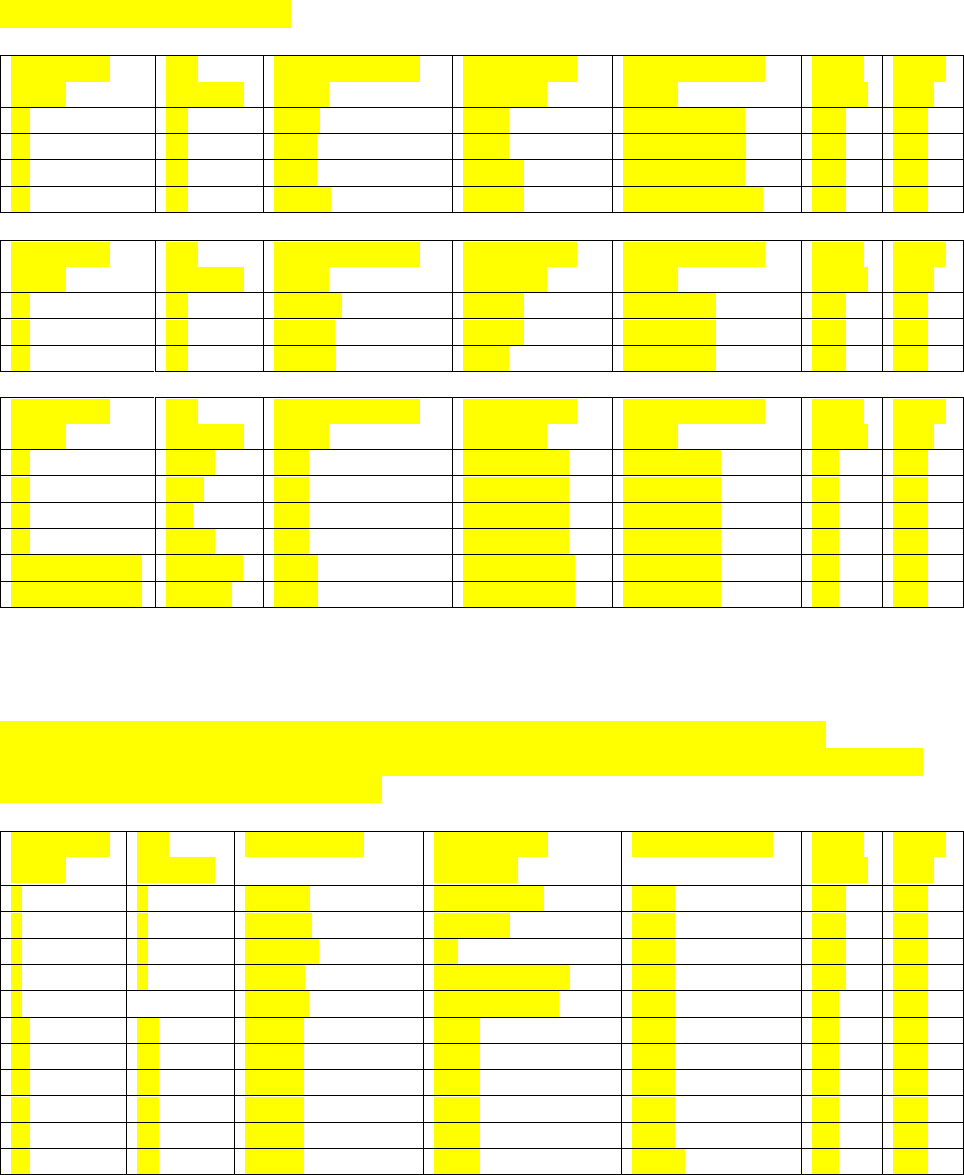
APPENDIX C: EVENT PROGRAMMING
Page 191 MRC-565 Packet Data Radio Operations & Maintenance
Discrete Inputs and Outputs
Connector
Name
Pin
Number
External Signal
Name
Direction or
Function
Internal Signal
Name
MRC
-565A
MRC
-565
J8
36
DTR
Input
TP3 +/- 10V
Yes
Yes
J8
32
RTS
Input
DSR +/- 10V
Yes
Yes
J8
31
CTS
Output
TP4 +/- 10V
Yes
Yes
J8
34
RING
Output
AVEC +/- 10V
Yes
Yes
Connector
Name
Pin
Number
External Signal
Name
Direction or
Function
Internal Signal
Name
MRC
-565A
MRC
-565
J8
12
MCLK
Output
TP2 0-5V
Yes
Yes
J8
28
MDIR
Output
TP1 0-5V
Yes
Yes
J8
13
MSET
Input
TP0 0-5V
Yes
Yes
Connector
Name
Pin
Number
External Signal
Name
Direction or
Function
Internal Signal
Name
MRC
-565A
MRC
-565
J8
19,20
IN1
OptIsoInput
TP5 0-5V
No
Yes
J8
18,3
IN2
OptIsoInput
TP6 0-5V
No
Yes
J8
1,2
IN3
OptIsoInput
TP7 0-5V
No
Yes
J8
16,17
IN4
OptIsoInput
TP10 0-5V
No
Yes
J8 (no,com,nc)
15,14,29
RO1
RelayOutput
TP11 0-5V
No
Yes
J8 (no,com,nc)
11,26,9
RO2
RelayOutput
TP12 0-5V
No
Yes
Analog Input Channels
The Analog input channels are read using a 12-bit A/D converter. Each of these has a
corresponding scaling factor and offset that is set using the SCALE command. The MRC-565A
has only the first four internal channels.
Connector
Name
Pin
Number
Signal Name
Direction or
Function
Internal Signal
MRC
-565A
MRC
-565
–
–
FPWR
Tx Fwd Pwr
AN0
Yes
Yes
–
–
RPWR
Rev Pwr
AN1
Yes
Yes
–
–
DETRF
SP
AN2
Yes
Yes
–
–
LBAT
Loaded Battery
AN3
Yes
Yes
–
TEMP
Internal Temp
AN4
No
Yes
J8
38
ADC1
Input
AN5
No
Yes
J8
39
ADC2
Input
AN6
No
Yes
J8
40
ADC3
Input
AN7
No
Yes
J8
37
ADC4
Input
AN8
No
Yes
J8
42
ADC5
Input
AN9
No
Yes
J8
41
ADC6
Input
AN10
No
Yes

APPENDIX C: EVENT PROGRAMMING
Page 192 MRC-565 Packet Data Radio Operations & Maintenance
External Input/Outputs (XIO)
When the XIO controller is attached to the MRC-565 or the MRC-565C, then 8 additional
discrete inputs, 10 discrete outputs, 2 counters and 6 analog inputs are available. The controller
uses three I/O lines, MCLK, MDIR and MSET, for a high speed synchronous port, and can input
and output packets for communicating with the XIO controller.
External Signal Name
Direction or Function
Internal Signal
Name
XIN1
Discrete Input
Port C, bit 2
XIN2
Discrete Input
Port C, bit 1
XIN3
Discrete Input
Port B, bit 7
XIN4
Discrete Input
Port B, bit 6
XIN5
Discrete Input
Port B, bit 5
XIN6
Discrete Input
Port B, bit 4
XIN7
Discrete Input
Port B, bit 3
XIN8
Discrete Input
Port A, bit 4
XIC1
High Speed Input Counter
---
XIC2
High Speed Input Counter
---
XOUT1
Discrete Output
Port D, bit 7
XOUT2
Discrete Output
Port D, bit 6
XOUT3
Discrete Output
Port D, bit 5
XOUT4
Discrete Output
Port D, bit 4
XOUT5
Discrete Output
Port D, bit 3
XOUT6
Discrete Output
Port D, bit 2
XOUT7
Discrete Output
Port D, bit 1
XOUT8
Discrete Output
Port D, bit 0
XOUT9
Discrete Output
Port C, bit 7
XOUT10
Discrete Output
Port C, bit 8
XADC1
10-Bit Analog Input
Port A, bit 0
XADC2
10-Bit Analog Input
Port A, bit 1
XADC3
10-Bit Analog Input
Port A, bit 5
XADC4
10-Bit Analog Input
Port E, bit 0
XADC5
10-Bit Analog Input
Port E, bit 1
XADC6
10-Bit Analog Input
Port E, bit 2

APPENDIX D: INSTALLATION DETAILS
Page 193 MRC-565 Packet Data Radio Operations & Maintenance
APPENDIX D:
INSTALLATION DETAILS
APPENDIX D: INSTALLATION DETAILS
Page 194 MRC-565 Packet Data Radio Operations & Maintenance
APPENDIX D: INSTALLATION DETAILS
Site selection and general installation guidelines are provided in this section, including
instructions for cabling, antenna and power source connections. Power up procedures,
initialization and functional test procedures are described that should be performed prior to
placing the MRC-565 on-line within the network.
Site Selection
There are 5 important factors to consider in selecting an optimum site:
1. External noise/interference
2. DC power source
3. Horizon angle
4. Antenna type
5. Antenna height
External Noise/Interference
Noise and signal interference can reduce the performance of the MRC-565. The most common
sources of noise and interference are as follows:
Cosmic Noise
Power Line Noise
Auto Ignition Noise
Computer-Generated Interference
External Signal Interference
Cosmic Noise
Cosmic noise is the limiting noise factor in a meteor burst system. This noise is generated by star
systems in the galaxy and is frequency dependent. The noise is approximately 15 dB above
thermal at 40 MHz and 13 dB above thermal at 50 MHz. This noise is diurnal in nature. It is the
highest when the antennas are pointed directly at the center of the galaxy and lowest when they
are pointed at right angles to it. Daily variations of 3 to 4 dB can be expected. An optimal
meteor burst site is one that is limited only by cosmic noise.
Power Line Noise
One of the main sources of manmade noise are high voltage power lines. Noise on these lines is
generated by high voltage breakdown occurring on power line hardware such as transformers
and insulators. This noise can be seen with an oscilloscope at the Receiver IF test point as a
series of spikes that occur every 8 ms (1/60 Hz) or every 10 ms (1/50 Hz). The level of the spikes
will be much higher than the normal background noise floor. The number of spikes can vary,
depending upon the level of interference, from one or two every 8-10 ms to several dozen every
8-10 ms. The impulse noise blanker in the MRC-565 will remove a large amount of this noise.

APPENDIX D: INSTALLATION DETAILS
Page 195 MRC-565 Packet Data Radio Operations & Maintenance
However, as the number of spikes increase, the effectiveness of the blanker is reduced. When
setting up a site always look at the IF test point with a scope to determine the level of the power
line noise interference. It is mandatory that power line noise be avoided for an optimum site. Try
to place the receiver antenna well away from power lines.
NOTE.
Power companies are required to properly maintain their power lines to reduce noise. Call
the local utility in case of severe noise.
Automobile Ignition Noise
Automobile ignition noise is generated by all gasoline engines and is a result of the high voltage
required to fire the spark plugs. Auto ignition noise is similar to power line noise with the
exception that it does not have the 8-10 ms period which is associated with power line noise.
Computer-Generated Interference
All computers and printers contain high-speed circuits that generate spurious signals throughout
the 37-50 MHz band. Interference will result if any of these signals couple into the antenna at
the MRC-565 receive frequency. To minimize this type of interference, try to keep the antenna
away from computers by at least 100 feet. The noise blanker will not suppress computer-
generated interference.
Signal Interference
This type of interference will occur whenever another transmitter is producing harmonics at the
receiver center frequency of the MRC-565. Antenna nulling and spatial separation can be used
to reduce this type on interference.
NOTE
With XTERMW installed (see Section 3.3), the STAT command can be used to determine
the site antenna noise levels. Ideally, the background noise levels should be less than –115
dBm.
DC Power Source
The MRC-565 requires a 12 (11.0-16.0) VDC power source. The average standby current at an
input voltage of 13.0 VDC is about 150 ma in a full operating mode (w/o GPS) without any low
power modes (LPM) enabled. When the unit transmits it requires about 25 amps for 100 msec.
An automobile battery provides an excellent power source. When operating from a battery with
Solar Panel Charger low power modes can be used to reduce current drain in receive mode.
If there is no AC power available a solar panel can be used to charge the battery. The size of the
solar panel is determined by the solar radiation available at the location of the site. In most
locations in the USA, a 40 watt solar panel will suffice. At higher elevations, where winter

APPENDIX D: INSTALLATION DETAILS
Page 196 MRC-565 Packet Data Radio Operations & Maintenance
temperatures are below freezing, a larger panel will have to be used. Consult MRC or contact
the solar panel manufacturer to perform this calculation for you and make a recommendation.
The power cable between the battery and the MRC-565 should be kept shorter than 10 feet and
rated at #14 AWG or lower. (See Section 3.2.2.1 for more details.)
CAUTION
The MRC-565 does not have an internal fuse and consideration should be given to
installing an external fuse between the battery and 565.
Horizon Angle
To obtain maximum performance in an MBC network the station must be installed on level flat
ground to provide a good ground plane. Lack of a good ground plane can reduce link
performance by a factor of two. Furthermore, the terrain in front of the antenna must be free of
buildings, bridges and other obstructions for a distance at least 30 times the height of the
antenna. Trees and other shrubbery do not present a problem if they are kept at least 20 feet (6
meters) from any of the antenna elements.
The antenna for MBC operation generally does not require a tilt angle and can be mounted
parallel to the ground. In the case of very short ranges (200-300 miles) and obstructions
exceeding 5 from horizontal a tilt angle may be advantageous. Please consult MRC’s sales
department for specific recommendations.
Antenna Selection
Horizontal polarization is normally used in a meteor burst network. The simplest antenna to use
is a dipole, however, a Yagi antenna will provide an improvement in performance by a factor
from 2 to 4, depending on the number of elements used.
DIPOLE ANTENNA

APPENDIX D: INSTALLATION DETAILS
Page 197 MRC-565 Packet Data Radio Operations & Maintenance
3-ELEMENT YAGI ANTENNA
The information bandwidth of the system is less than 20 KHz, therefore, a very narrow
bandwidth antenna may be used when operating on a single frequency. In a two-frequency
network the bandwidth of the antenna must be wide enough to accommodate both frequencies.
The antenna must provide a 50 load. In the U.S. USDA SNOTEL Network, two frequencies
are used:
TX = 41.61 MHz and RX = 40.67 MHz. The Bandwidth of the antenna used is 1 MHz.
Always consult with MRC’s engineering department for assistance when any questions arise
with respect to antenna selection.
Assembly instructions are included with each antenna. Please refer to these for proper assembly
for all antenna elements.
Antenna Height
The height of the antenna for MBC operation should be optimized as a function of the distance
between the remote station and the master station. A plot of optimum antenna height versus
range is shown below.
REMOTE STATION ANTENNA HEIGHT FOR METEOR BURST
0
5
10
15
20
25
30
35
40
45
50
55
60
65
70
75
80
85
90
95
100
100
150
200
250
300
350
400
450
500
550
600
650
700
750
800
850
900
950
1000
Antenna Height (ft)
RANGE (mi)
Best Antenna Height
4
0
M
h…

APPENDIX D: INSTALLATION DETAILS
Page 198 MRC-565 Packet Data Radio Operations & Maintenance
The antenna cable length must be kept as short as possible to minimize line losses. Try to
maintain a line loss between the antenna and the MRC-565 to less than 2 dB.
A table of cable loss (at 50 MHz) for various types of co-ax cables is given below for reference.
CABLE TYPE
Loss/100 feet
(dB)
Diameter
(Inches)
Weight/100 feet
(lbs.)
RG 223, RG 58
3.0
.211
3.4
RG 214, RG 8
1.8
.425
12.6
RG 17
1.2
.870
20.1
LDF4A-50 ½ inch heliax
.48
.500
15.0
LDF5A-50 7/8 inch heliax
.26
.875
33.0
Human Exposure To Radio Frequency Electromagnetic Fields
For fixed applications, antenna gains and mounting techniques can vary depending on the
application. A Yagi antenna, not exceeding 10 dBi, must be mounted a minimum of .90 meters
from humans. Lower gain antennas (5.2 dBi), such as side mount dipoles must be mounted no
closer than .52 meters. This separation will provide RF shielding between the antenna and
humans, reducing the RF exposure to levels below that specified in FCC OET Bulletin 65.
Always disable the transmitter when working on the antenna and/or co-ax cable.
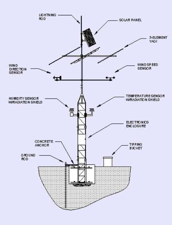
APPENDIX D: INSTALLATION DETAILS
Page 199 MRC-565 Packet Data Radio Operations & Maintenance
Equipment Installation
The MRC-565 operates over a temperature range from -30C to +60C and is housed in a
aluminum case. A NEMA waterproof enclosure is recommended for outdoor installations. To
ensure proper operation, shielded cable is recommended for all connectors. Also, use adequate
strain relief on all cables and a weatherproof seal at the entry point of the enclosure. A typical
remote station installation is shown below.
Figure 12. Typical Remote Station with 3-Element YAGI Antenna

APPENDIX D: INSTALLATION DETAILS
Page 200 MRC-565 Packet Data Radio Operations & Maintenance
In general, the following components are required for a typical remote station installation
(sensors are not specified since they will vary from site to site).
ITEM
DESCRIPTION
QTY
PART NUMBER
1
Packet Data Radio
1
MRC-56500300
2
Data Logger (optional)
1
CR10X/CR1000 or
equivalent
3
Antenna (choose one of the following):
Folded Dipole or 3-Element Yagi
1
MBD or MBY-3
4
40-60 Watt Solar Panel (with 20 ft., 12 AWG
Cable)
1
5
Mounting Bracket for Solar Panel
1
6
Solar Panel Regulator, 6A
1
7
Shielded Cable for Solar Panel
20 ft.
8
12V, 100 A-H, Rechargeable, Sealed Battery
1
9
6’ Power Cable
1
10
Lightning Surge Protector (Coax)
1
11
Aluminum NEMA Enclosure
1
12
Mounting Plate for NEMA Enclosure
1
13
50’ RG-214N Coax Cable
1
14
Conduit Assembly
Lot
15
Hose Clamps
Lot
16
Ground Rod Assembly
1
17
Tower Assembly
1
18
Entry Connectors for NEMA Enclosure
Lot
19
Padlock
1
20
Lightning Rod
1

APPENDIX E: INTEROPERABILITY
Page 201 MRC-565 Packet Data Radio Operations & Maintenance
APPENDIX E:
INTEROPERABILITY
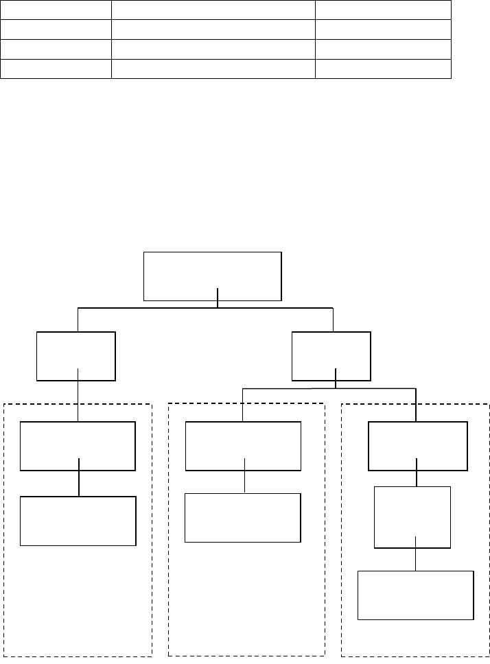
APPENDIX E: INTEROPERABILITY
Page 202 MRC-565 Packet Data Radio Operations & Maintenance
APPENDIX E: INTEROPERABILITY WITH OTHER MRC PRODUCTS
MBNET200 is the network software and operating system that is embedded within the MRC-
565. This network software module is also embedded in MRC’s other products and provides
interoperability among MRC’s three primary networks: Meteor Burst, DataNet and FleetTrak.
MODEL NO.
DESCRIPTION
MODULATION
MRC-525
Meteor Burst Master Station
BPSK
MRC-565
Packet Data Radio
BPSK
MRC-565
Packet Data Radio
GMSK
There are two network protocols that are embedded within MBNET200:
Meteor Burst Communications Protocol (MBC)
Extended-Line-of-Sight Protocol (ELOS)
MRC configures these products and protocols into three distinct networks as shown in the figure
below.
Figure 13. MRC Networks
NETWORK SOFTWARE
MBNET200
ELOS
PROTOCOL
FleetTrakTM
BASE STATION
(LOS)
REPEATER
STATION
(LOS)
REMOTE STATION
(LOS)
MBC
PROTOCOL
Meteor Burst
REMOTE STATION
(TRANSPONDER)
MASTER STATION
(PROBER)
DataNet
MASTER STATION
(LOS)
REMOTE STATION
(LOS)

APPENDIX E: INTEROPERABILITY
Page 203 MRC-565 Packet Data Radio Operations & Maintenance
The three primary products are used within the three networks as follows:
MRC-525
MRC-565
Meteor Burst
Master
Remote
X
X
DataNet
Master
Remote
X
X
FleetTrakTM
Base
Repeater
Remote
X
X
X
The MRC-565 Packet Data Radio is configurable into six different operating modes. Each mode
is a function of its specific role within one of the three networks.
MODE
NETWORK
PROTOCOL
FUNCTION
Transponder
Meteor Burst
MBC
As a remote station in a meteor burst
network
Master
DataNet
ELOS (CSMA)
Direct communications with other master
stations in networks that have no landlines
or a central Host. It also communicates
with remote stations but not repeaters.
Base
FleetTrakTM
ELOS (CSMA
& TDMA)
It is connected by landline to a central
Host. It communicates with both remotes
and repeaters.
Repeater
FleetTrakTM
ELOS (CSMA
& TDMA)
As a repeater it communicates with base
stations, other repeaters and remote
stations.
Remote
FleetTrakTM
ELOS (CSMA
& TDMA)
As a remote it communicates with base
stations, repeaters and other remote
stations.
Remote
DataNet
ELOS (CSMA)
As a remote it communicates with Master
Stations and other remote stations.
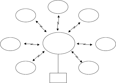
APPENDIX E: INTEROPERABILITY
Page 204 MRC-565 Packet Data Radio Operations & Maintenance
The MRC-565 operating with BPSK modulation has a 6 dB improvement in sensitivity over the
MRC-565 operating with GMSK modulation, however, its data rate is limited to 4.0 kbps. The
MRC-565 operating in GMSK has a maximum data rate of 9.6 kbps. Therefore, the choice
between using the MRC-565 or the MRC-565C is a trade-off between performance and data
rates.
For reference, each of the three networks are briefly described below.
Meteor Burst
Meteor Burst is a meteor burst communication system (MBCS) that uses the MBC protocol. An
MBCS system operates seamlessly between ground and meteor burst for the transmission of
digital data. Groundwave will generally cover distances up to about 100 miles and meteor burst
seamlessly extends this coverage to 1,000 miles. Groundwave provides instantaneous
communications while meteor burst reflects signals off the ionized trails created by
micrometeors entering the atmosphere at a height of 60 miles above the earth’s surface. These
trails, called bursts, are random but predictable in number and last from a few milliseconds to
several seconds. During this brief period of time, information is exchanged between a master
station and a remote station. MBCS is a natural time division multiplexed (TDMA) system,
therefore thousands of remote stations can operate into one master station on a single frequency.
In its simplest form, a Meteor Burst network consists of one master station operating in a star
configuration to all remote stations located within its RF communication range of 1,000 miles.
The master station is an MRC-520B and the remote stations are all MRC-565s. The master
station is normally connected to a host computer in a Data Center or a customer’s office. The
network operates on either a single frequency for half-duplex or two frequencies for full-duplex.
The master station operates in the “probing” mode and the remote stations operate in the
“transponder” mode. That is, when a remote station hears a probe signal from the master station
it responds by transmitting the data stored in its buffer. The remote stations are programmed to
respond at specific time intervals (e.g., hourly) and also based on events that may have occurred
MASTER
STATION
REMOTE
REMOTE
REMOTE
REMOTE
REMOTE
REMOTE
REMOTE
HOST
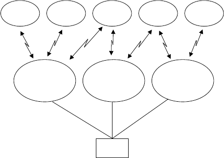
APPENDIX E: INTEROPERABILITY
Page 205 MRC-565 Packet Data Radio Operations & Maintenance
at the remote station site. Programming may be done on-site or from any off-site location using
a web browser.
Multiple master stations are interconnected into a clustered star configuration as shown below.
The remote stations transmit their data to whichever master station probe is received. Multiple
master stations will significantly improve the performance of the network because of the
additional RF links available to each remote station.
For a complete description of Meteor Burst networks, refer to MRC’s web site or the documents
referenced in Section 1.2.
The specific O&M manuals for the products used in a Meteor Burst network are:
MAN-OM-525 Meteor Burst Master Station
MAN-OM-MRC-565 Meteor Burst Remote Station
MASTER
STATION
REMOTEREMOTE REMOTE REMOTE REMOTE
HOST
MASTER
STATION
MASTER
STATION

APPENDIX E: INTEROPERABILITY
Page 206 MRC-565 Packet Data Radio Operations & Maintenance
DataNet
DataNet is an autonomous packet switched network that uses the ELOS protocol and does not
require the use of landlines or a central Host. A typical network configuration is shown below.
DataNet is an ELOS system that uses the same robust protocols developed for meteor burst,
however, it operates line of sight only and relies on groundwave diffraction, atmospheric
diffraction and tropospheric propagation. These various modes of operation, along with robust
protocols and low band VHF, provide communication ranges from 50 to 100 miles. DataNet is
basically a cellular network with either an MRC-565 or MRC-565C operating as the master
station for each cell. DataNet operates as either a single cell or can be expanded to include
hundreds of cells. Adaptive network connectivity, two-way messaging and data acquisition are
features embedded within the network.
All network data is routed between master stations and their respective remote stations. No
repeaters are used. Access to the network is made at any node by connecting an operator
terminal (e.g., a laptop or PC) to one of the RS-232 ports that are available at each of the master
station and remote station locations. If desired, a Host may be interfaced to any one of the
master stations using a landline.
The remote stations are normally at fixed locations and can interface to a variety of peripheral
devices.
The connectivity between specific master stations and remotes are normally defined at the time
the network is designed and deployed. If one master station goes down, the remote stations
assigned to it automatically choose their own connectivity with a new master station based on
their proximity to the master station, signal strength and other link parameters. Connectivity
tables are automatically updated and exchanged among all master stations whenever a remote
station attaches itself to a new master station.
The network operates on a single frequency. The ELOS protocol uses CSMA for
communication between all network nodes.
MASTER
STATION
REMOTE
REMOTE
REMOTE LAPTOP
MASTER
STATION
MASTER
STATION
CLIENT PC
DATA
LOGGER
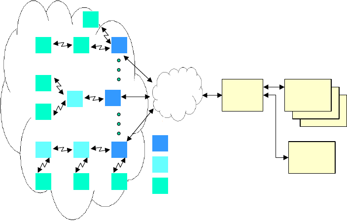
APPENDIX E: INTEROPERABILITY
Page 207 MRC-565 Packet Data Radio Operations & Maintenance
FleetTrakTM
The FleetTrakTM network is used for applications that require the position of mobile resources to
be reported in real-time and at varying update rates. A typical FleetTrak network is shown
below. One or more Data Centers are normally used for the central collection and distribution of
data to a customer’s office. The network can be as small as one base station or may be comprised
of thousands of base stations, repeaters and remote stations. The networks are used for position
reporting in mobile applications (AVL), fixed site data collection (SCADA) and messaging.
Either an MRC-565 or MRC-565C may be used in a FleetTrakTM network.
The FleetTrakTM network operates line-of-sight using groundwave. The range of communication
by groundwave is primarily determined by diffraction around the curvature of the earth,
atmospheric diffraction and tropospheric propagation. These ranges are successfully extended by
MRC from 50-100 miles through the use of robust protocols, sensitive receivers and short
packetized messages.
The FleetTrakTM network uses the ELOS protocol and combines CSMA (carrier sense multiple
access) and TDMA (time division multiple access) for achieving a channel utilization greater
than 90%.
When a remote station (mobile) desires to establish connectivity with the network it sends a “poll
request”, which specifies data type and desired update interval, to the nearest base station using
the CSMA mode. The base station acknowledges this request and adds the mobile to its TDMA
polling database. The mobile then sends its data in the TDMA mode when polled by the base
station.
Since one base station may be in contact with hundreds of mobiles at any one time, it organizes
the responses from up to 10 mobiles on a single transmission burst (TDMA). The ten mobiles
CLIENT’S
OFFICES
DATA
NETWORK
DATA CENTER
OR
HOST
CLIENT’S
OFFICES
B
R
M
BASE STATION
REMOTE STATION (FIXED OR MOBILE)
REPEATER STATION
M B
M
M
M
M
RB
R
M M M
R B
ELOS RF NETWORK
OTHER
CLIENTS
APPENDIX E: INTEROPERABILITY
Page 208 MRC-565 Packet Data Radio Operations & Maintenance
will then report in sequence, in accordance with their assigned transmit slots. The base station
acknowledges the data received from each of the ten mobiles and then polls ten more mobiles on
the next burst transmission.
Using the above techniques, there is no contention and all reports are delivered at a 90% channel
utilization rate. With these efficiencies, sufficient channel time is still available for two-way
messaging and various other non-periodic data transfers using the CSMA mode.
The MRC-565C is the only VHF transceiver used in the network. It can be dynamically
configured to operate in three distinct modes: as a remote (mobile), as a base station or as a
repeater station. As a base station, it also maintains RF communications with all mobiles
operating within its own cell network, routing all data to a Host through a data network
connected to one of its RS-232 ports.
When a direct connection to a central Host is not available at a particular base station site, the
MRC-565C is configured to operate as a repeater station. As a repeater station, it routes all data
to the nearest base station for subsequent delivery to the Host. Multiple repeater links may be
chained together for expansion of the network.
As a mobile, the MRC-565C is free to roam throughout the network, automatically linking with
the nearest base station or repeater. When mobiles are out of range of a repeater or base station,
but within range of other mobiles, they will automatically select another mobile as their repeater
into the network. The only mobiles that may be selected are ones that have connectivity with a
repeater or base station.

APPENDIX E: INTEROPERABILITY
Page 209 MRC-565 Packet Data Radio Operations & Maintenance
Related Documents
The documents that describe each product’s operating role within each of the three networks is
shown below.
OPERATION
OF THE
MRC-565
IN A
FleetTrakTM NETWORK
MAN-OM-MRC-565C -
FleetTrakTM
OPERATION
OF THE
MRC-565
IN A
DataNet NETWORK
MAN-OM-MRC-565C -
DataNet
OPERATION
OF THE
MRC-525
IN A
Meteor Burst NETWORK
OPERATION
OF THE
MRC-565
IN A
FleetTrakTM NETWORK
MAN-OM-MRC-565 -
FleetTrakTM
OPERATION
OF THE
MRC-565
IN A
DataNet NETWORK
MAN-OM-MRC-565 -
DataNet
OPERATION
OF THE
MRC-565
IN A
Meteor Burst NETWORK
MAN-OM-MRC-565 - Meteor
BurstTM
MBNET200
A COMPLETE LIST
OF ALL
COMMANDS AND PRINTOUTS
Figure 14. Network Document Tree