Media Vision USA MVALSSTFM Stationary Transmitter User Manual MV ALS STFM Install
Media Vision USA Stationary Transmitter MV ALS STFM Install
UserManual.wiki
>
Media Vision USA
>
MVALSSTFM User Manual
>
Manual End User
Contents
1.
Manual End User
2.
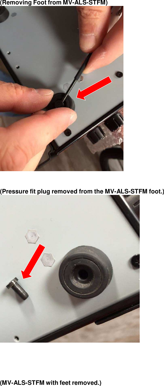
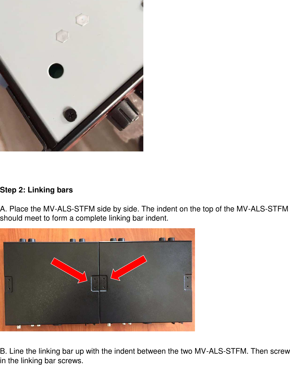
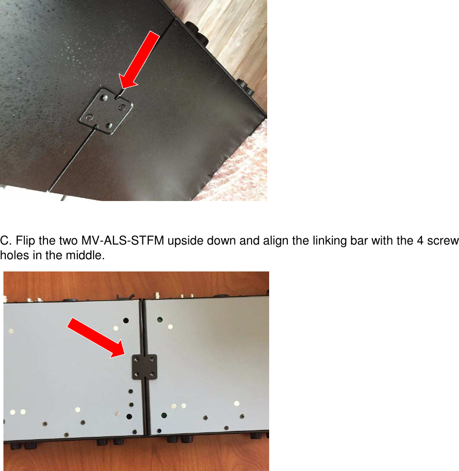
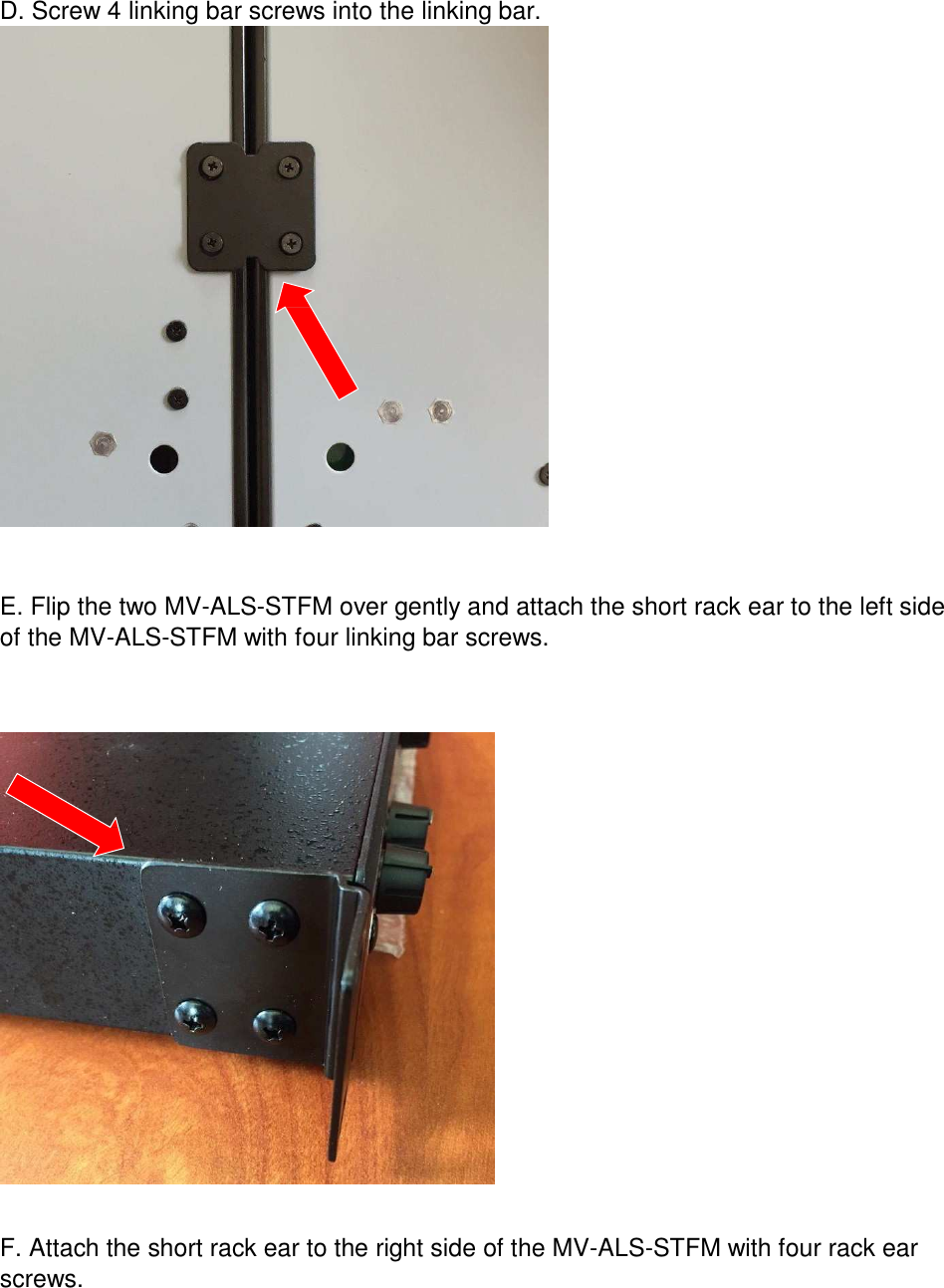
Manual Installation
Manual End User
Navigation menu
Upload a User Manual
Namespaces
Wiki Guide
HTML
PDF
Info
Views
User Manual
Discussion / Help
Navigation