Media Vision USA MVALSSTFM Stationary Transmitter User Manual MV ALS STFM Install
Media Vision USA Stationary Transmitter MV ALS STFM Install
Contents
- 1. Manual End User
- 2. Manual Installation
Manual End User

MV-ALS-STFM
Professional Installation Guide

Table of Contents
Overview 1 - 2
Introduction 2
Product Highlights 2
Product Package 2
General Information 3
RF Power 3
Single MV-ALS-STFM Rack Kit Installation 4 - 6
Double MV-ALS-STFM Rack Kit Installation 6 – 12
Helical Antenna 12 – 13
Remote Dipole Antenna 14 – 17
Installation Technical Information 17 - 18

Overview
This manual covers basic configuration and installation of the Media Vision Assistive
Listen System which consists of the MV-ALS-STFM (Stationary Base Transmitter), MV-
ALS-PRFM (Portable Receiver), MV-ALS-AT01 (Helical Antenna), and MV-ALS-AT02
(Remote Dipole Antenna). Together these devices are classified by the FCC as a
professional install device. To be in compliance with FCC guidelines, the radios must be
installed with one of the approved antennas listed in this document. The MV-ALS-STFM
is currently FCC certified for use with three external antennas.
Antenna Part # Description Power Handling
Capability
MV-ALS-AT01 8.89” Helical Antenna 20 mW, Nominal
M
V
-
AL
S
-
A
T
02
7
.
09
”
R
e
m
ote
Di
p
ole An
t
e
n
na
20
m
W
,
N
o
m
in
a
l
The MV-ALS-STFM Base Unit works in conjunction with the MV-ALS-PRFM. Please
see the Media Vision Assistive Listening User Manual for general information on overall
system implementation and software configuration.
Federal Communication Commission Interference Statement
This device complies with Part 15 of FCC Rules and Regulations. Operation is subject
to the following two conditions: (1) This device may not cause harmful interference and
(2) this device must accept any interference received, including interference that may
cause undesired operation. This equipment has been tested and found to comply with
the limits for a Class B digital device, pursuant to Part 15 of the FCC Rules. These limits
are designed to provide reasonable protection against harmful interference in a
residential installation. This equipment generates, uses, and can radiate radio-
frequency energy and, if not installed and used in accordance with these instructions,
may cause harmful interference to radio communications. However, there is no
guarantee that interference will not occur in any particular installation. If this equipment
does cause harmful interference to radio or television reception, which can be
determined by turning the equipment off and on, the user is encouraged to correct the
interference by one of more of the following measures:
1) Reorient the antenna;
2) Increase the separation between the affected equipment and the unit;
3) Connect the affected equipment to a power outlet on a different circuit from that
which the receiver is
connected to;
4) Consult the dealer and/or experienced Assistive Listening Technician.
FCC ID: 2AHER-MVALSSTFM

Warranty Information
The Media Vision Assistive Listening Core products carry a Lifetime Warranty against
manufactory defects. Please visit www.media-vision.com for more information.
Installation only by Professional Installers:
The Media Vision Stationary Base Transmitter requires professional installation. A
professional installer is required to install the MV-ALS-STFM. You must follow Part 15 of
the FCC rules, and specifically Part 15.203 pertaining to antenna requirements of an
intentional radiator.
The antenna installation may only be modified by a Mediavision authorized person, who
must be aware of the FCC regulations for such devices
1 Introduction
The Media Vision Assistive Listening system is a powerful stationary transmitter that
delivers a high quality personalized audio signal that allows everyone to understand.
2 System Highlights
• Operates on the FCC protected 72-76 Mhz FM bandwidth
• 57 programmable channels with settings lock
• Simultaneous operation of up to 6 channels Easy Integration:
• Balanced and unbalanced Inputs, Dante Interface
3 Product Package
The following items are included in the MV-ALS-STFM package:
• Stationary Base Transmitter (MV-ALS-STFM)
• Rack Kit (MV-ALS-RK01)
• Power Adapter Cord
• Programming Cable
4. General Information
4.1 Contents
The MV-ALS-STFM Stationary Base Transmitter comes with the Stationary Base
Transmitter, Rack Kit, Power Adapter Cord, and programming Cable. Required to make
the MV-ALS-STFM function properly are one of the two FCC approved Antenna:
A. MV-ALS-AT01 (Helical Antenna).
B. MV-ALS-AT02 (Remote Dipole Antenna)
4.2 Connections
See Media Vision Assistive Listening User Manual for detailed diagram for connecting
the system to a verified outlet.
MV-ALS-STFM
Input 1 XLR - TRS Combo Jack - Line, Mic,
Mic+PH
I
n
p
u
t 2
St
e
reo
RCA
Audio
O
u
t
St
e
reo
RCA. M
i
x
o
f A
u
x
a
nd
M
i
c Si
g
nal
He
a
d
p
ho
n
e
O
ut
1/
8
”
T
RS C
o
nne
c
t
o
r
Pro
g
ra
mm
ing
Ch
a
n
n
el E
n
able
/ D
i
s
a
ble & Cu
s
t
o
m
Lables Via Software
RF
Po
w
er
Lo,
M
id, Hi
Ant
e
nna
Co
n
nec
t
or
BNC
Po
w
er S
u
pply
DC
a
da
p
t
o
r
1
2 ~ 1
5
V,
1A
O
p
erating
t
e
m
pera
t
ure
ran
g
e
-
10
º
C
-
6
0ºC
NOTE: DO NOT APPLY DC POWER TO THE MV-ALS-STFM UNTIL THE ANTENNA
IS ATTACHED OTHERWISE DAMAGE TO THE RADIO MAY OCCUR.
5. Setting the Maximum RF Power
When installing MV-ALS-STFM we offer two FCC certified antennas options.
Only the antennas listed below are allowed to be used with the MV-ALS-STFM.
Antenna Model Antenna Gain Radio Max power
set
t
ing
M
V
-
AL
S
-
A
T
01
?
??
?
?
?
M
V
-
AL
S
-
A
T
02
?
??
?
?
?
NOTE: IT IS THE RESPONSIBILITY OF THE INSTALLER TO ENSURE THAT THE
FCC REQUIREMENTS DESCRIBED ABOVE ARE MET.
7. Installing single MV-ALS-STFM - Rack Kit
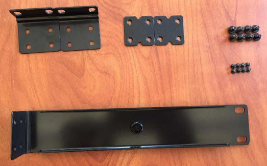
Rack Kit (Pictured below)
Includes (In Order):
1. (2) – Rack ears
2. (1) – Linking bars
3. (2) – Rack ear screws
4. (8) – Linking bar screws
5. (8) – Long rack ear
Note: For installation of (2) MV-ALS-STFM into Rack System please skip to section 8.
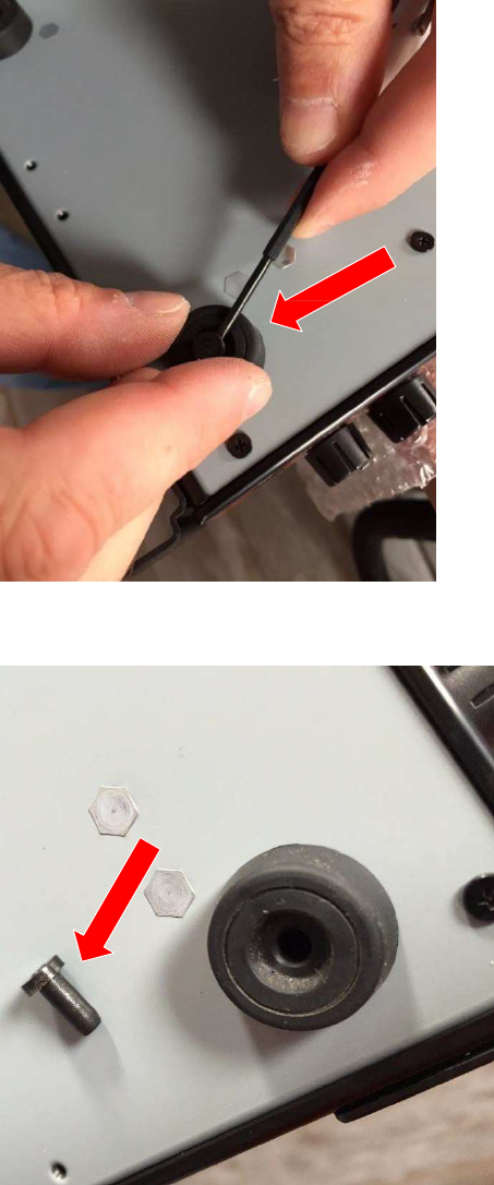
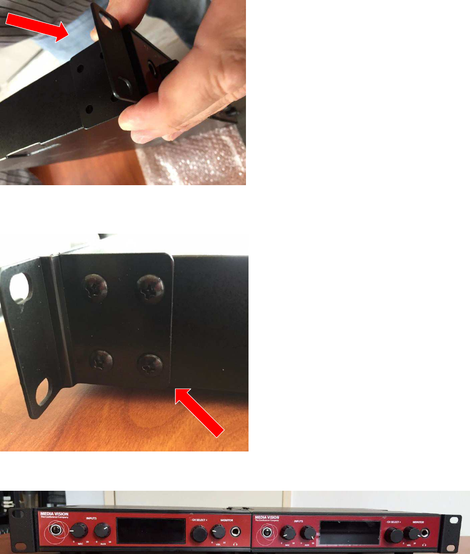
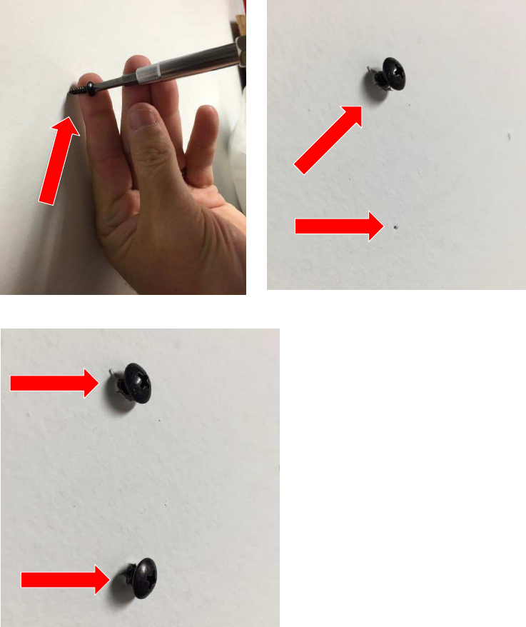
Step 1.
The feet on the MV-ALS-STFM are secured and locked in by a pressure fit plug.
Utilizing a flathead screwdriver or comparable tool, remove the (4) feet from the MV-
ALS-STFM by inserting it into the foot and gently lift the plug until you are able to
remove it.
Once you have removed the plug, grab the foot and gently pull it out of the MV-ALS-
STFM.
(Removing Foot from MV-ALS-STFM)
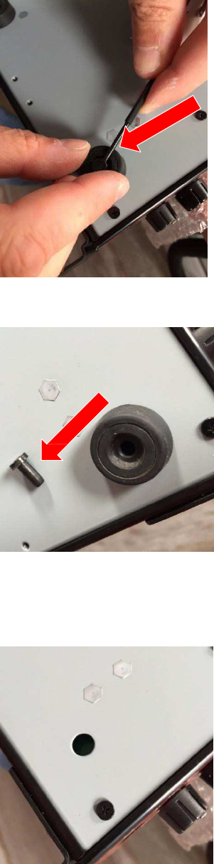
(Screw Removed from the MV-ALS-STFM Foot.)
(MV-ALS-STFM with feet removed.)
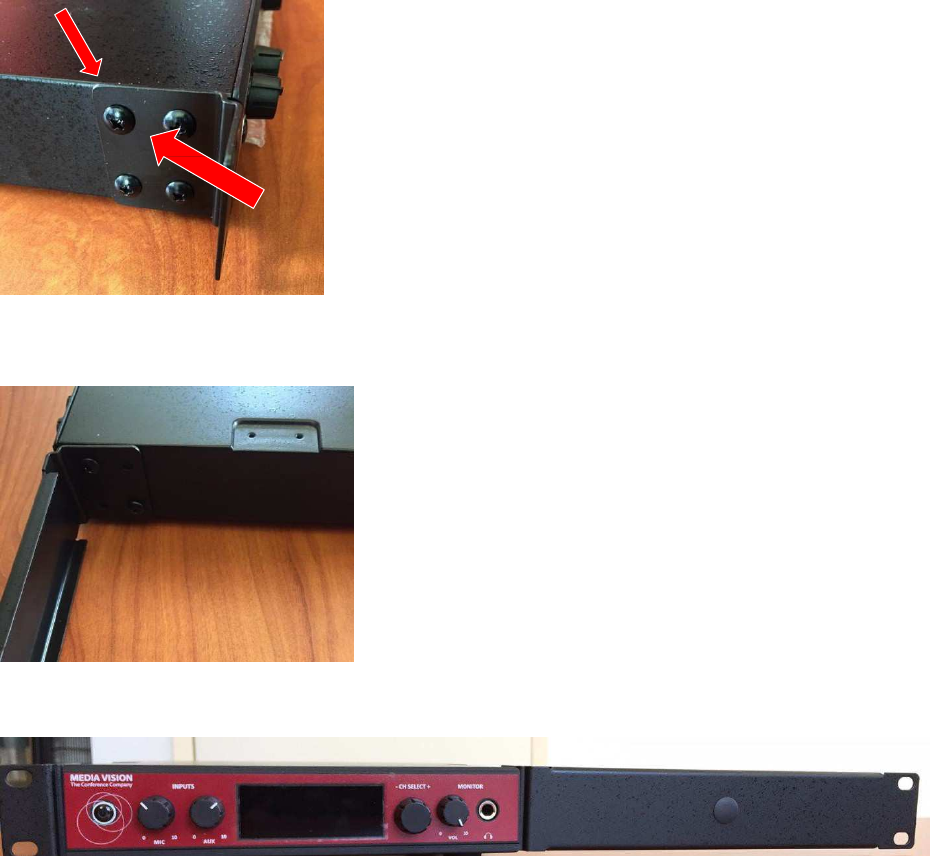
Step 2: Rack Ears
A. Attach the short rack ear to the left or right side of the MV-ALS-STFM with the four
rack ear screws.
B. Attach the long rack ear to the right or left side of the MV-ALS-STFM with four rack
ear screws.
(Rack Kit Installed on the MV-ASL-STFM)
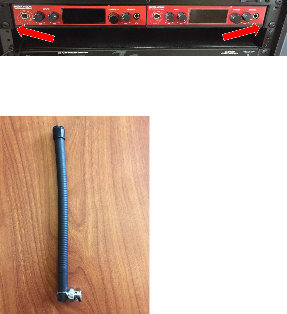
Step 3.
A. Select the position within the Rack System for your MV-ALS-STFM.
B. Place the MV-ALS-STFM in the Rack System and utilize rack screws (not included)
to secure both ends.
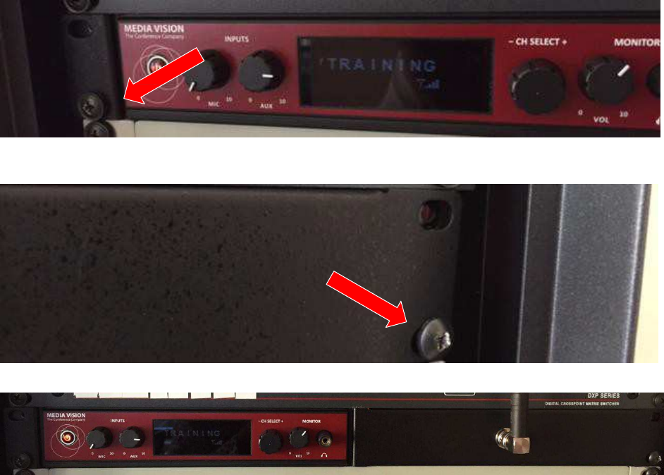
(
S
ho
r
t
r
a
ck
e
ar
s
c
r
e
w
ed
into
r
a
c
k
s
y
s
t
em
.
)
(Long rack ear screwed into rack system.)
(MV-ALS-STFM with Rack Kit installed in Rack System)
8. Installation of two MV-ALS-STFM - Rack Kit
Step 1. The feet on the MV-ALS-STFM are secured and locked in by a pressure fit plug.
Utilizing a flathead screwdriver or comparable tool, remove the (8) feet from the (2) MV-
ALS-STFM by inserting it into the foot and gently lift the pressure fit plug until you are
able to remove it.
Once you have removed the pressure fit plug, grab the foot and gently pull it out of the
(2) MV-ALS-STFM.
(Remo
v
ing
F
o
ot
f
r
om
M
V
-
A
L
S
-
S
T
F
M
)
(Pressure fit plug removed from the MV-ALS-STFM foot.)
(MV-ALS-STFM with feet removed.)
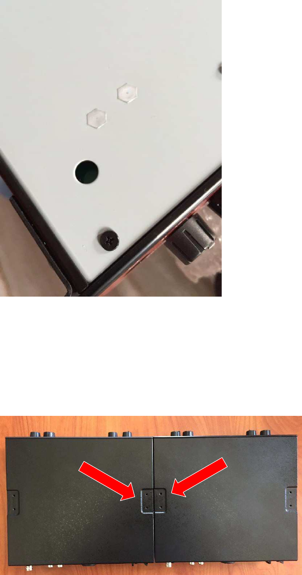
Step 2: Linking bars
A. Place the MV-ALS-STFM side by side. The indent on the top of the MV-ALS-STFM
should meet to form a complete linking bar indent.
B. Line the linking bar up with the indent between the two MV-ALS-STFM. Then screw
in the linking bar screws.
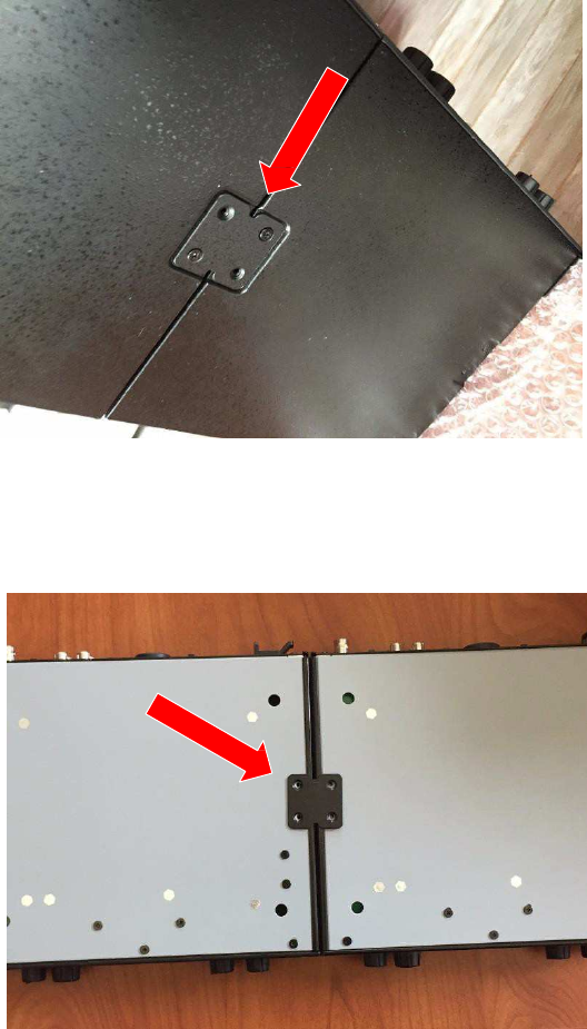
C. Flip the two MV-ALS-STFM upside down and align the linking bar with the 4 screw
holes in the middle.
D. Screw 4 linking bar screws into the linking bar.
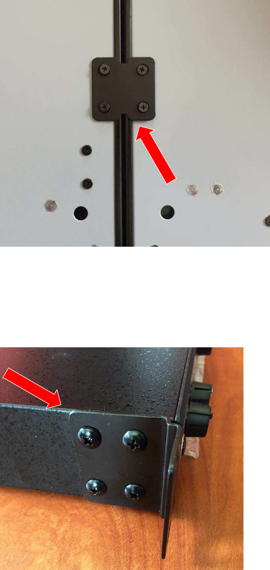
E. Flip the two MV-ALS-STFM over gently and attach the short rack ear to the left side
of the MV-ALS-STFM with four linking bar screws.
F. Attach the short rack ear to the right side of the MV-ALS-STFM with four rack ear
screws.
(Rack Kit Installed on two MV-ALS-STFM)
F. Place the two MV-ALS-STFM into the Rack System and utilize rack ear screws to
secure both ends
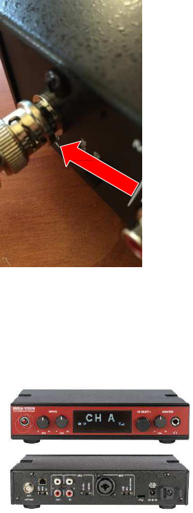
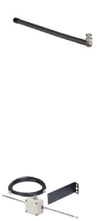
9. Helical Antenna Installation
Included:
(1) Helical Antenna
Step 1. Align the Helical Antenna with the BNC Antenna connector.
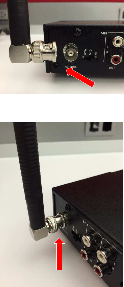
Step 2. Connect the Antenna and the BNC antenna connector. Secure and lock it into
place.
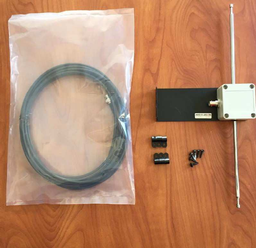
9. Remote Dipole Antenna Installation
Includes:
(1) Bracket with Mounted Antenna
(1) 25” Coaxial Cable
(6) Stoppers
(6) Screws.
Step 1. Choose the location where you’d like to install the Antenna Bracket.
When selecting the location of your Antenna avoid any metal obstructions or steel
beams between the Antenna and the receiver.
Once you have chosen the position where you’d like to mount the antenna. Utilizing #2
pencil, mark the position.
Step 2: Utilizing a screw driver, screw in the two bracket screws into the spots that were
marked. Do not screw them in all the way.
Step 3. Position the two openings on each end of the bracket onto the screws and slide
the bracket down until it can move no further.
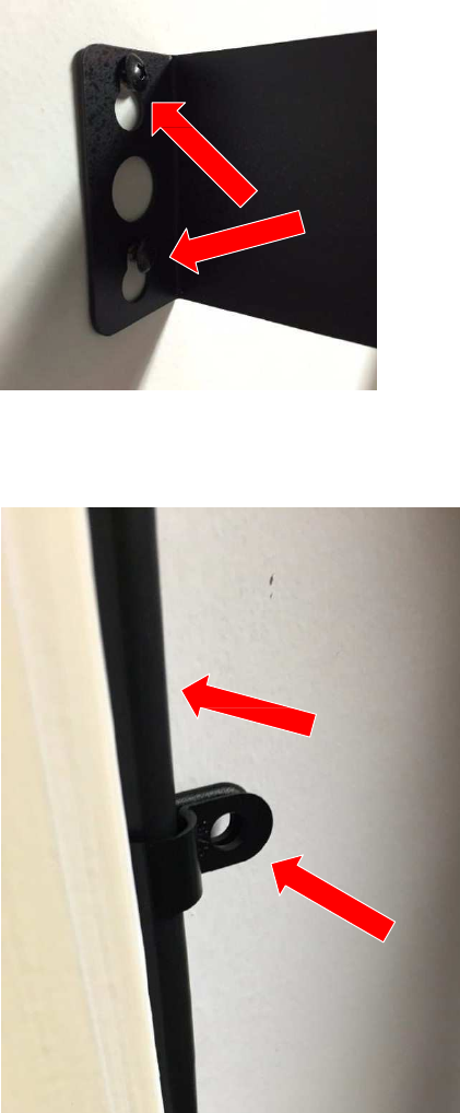
Step 4. Using the cable clips, secure the coaxial cable onto a flat surface. Make sure
that cable clips are at least 4 inches apart.
Step 5. Attach the coaxial cable to the BNC antenna connector on the back of the
transmitter. Secure and lock it into place.
8. Installation - Technical Information
8a. MV-ALS-STFM
Channels 57 (6 Simultaneous)
T
ran
s
m
iss
i
on
Ran
g
e
Up to
1,
5
00
ft.
SNR
80
d
B
F
r
e
q
uency
Response
70H
z
-
12Khz
D
i
st
o
rt
i
on
<
2%
D
i
splay
O
L
ED
I
n
p
u
t 1
X
LR
-
T
RS C
o
m
bo
Jack - Line, Mic,
Mic+PH
I
n
p
u
t 2
St
e
reo
RCA
Audio
O
u
t
St
e
reo
RCA. M
i
x
o
f
Aux and Mic Signal
He
a
d
p
ho
n
e
O
ut
1/
8
”
T
RS C
o
nne
c
t
o
r
Pro
g
ra
mm
ing
Ch
a
n
n
el E
n
able
/
Disable & Custom
Lables Via Software
RF Power Lo, Mid, Hi
Ant
e
nna
Co
n
nec
t
or
BNC
Po
w
er S
u
pply
DC
a
da
p
t
o
r
1
2 ~
15V, 1A
O
p
erating
temperature range
-
10
º
C
-
6
0ºC
Si
z
e
8.
4
6” X
8
.
26” X
1
.
96”
W
e
i
g
ht
3.7
lb
s
.
W
a
r
r
anty
Lifeti
m
e
Appro
v
als /
Certifications
F
C
C, RoHS
8b. MV-ALS-AT01
Dimensions 8.89” Height; 1.14” Distance from MV-ALS-STFM
Weight 2 oz.
Frequency Range 72-76 MHz
Nominal Impedance 50 Ω
VSWR 2:1 or Better
Power Handling Capability 20 mW, Nominal
Warranty 90 Days
8b. MV-ALS-AT02
Dimensions (41 mm) High, Collapsed; (970 mm) Extended; (180 mm)
Distance from Wall
Weight 245g
Frequency Range 72-76 MHz
Nominal Impedance 50 Ω
VSWR 3:1 or Better
Power Handling Capability 20mW, Nominal
Warranty 90 Days