Meteorcomm 54505003-01 Packet Data Radio Transceiver - Fixed or Mobile User Manual
Meteorcomm LLC Packet Data Radio Transceiver - Fixed or Mobile Users Manual
UserManual.wiki
>
Meteorcomm
>
54505003-01 User Manual
>
Users Manual
Contents
1.
Users Manual
2.
RF Users Guide
Users Manual
Navigation menu
Upload a User Manual
Namespaces
Wiki Guide
HTML
PDF
Info
Views
User Manual
Discussion / Help
Navigation
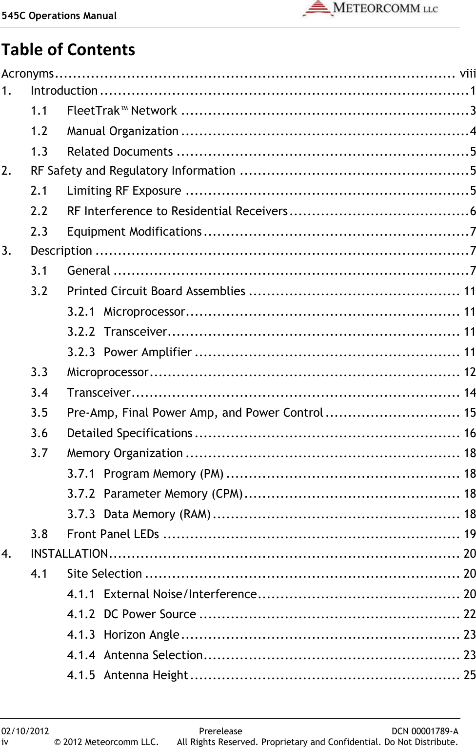
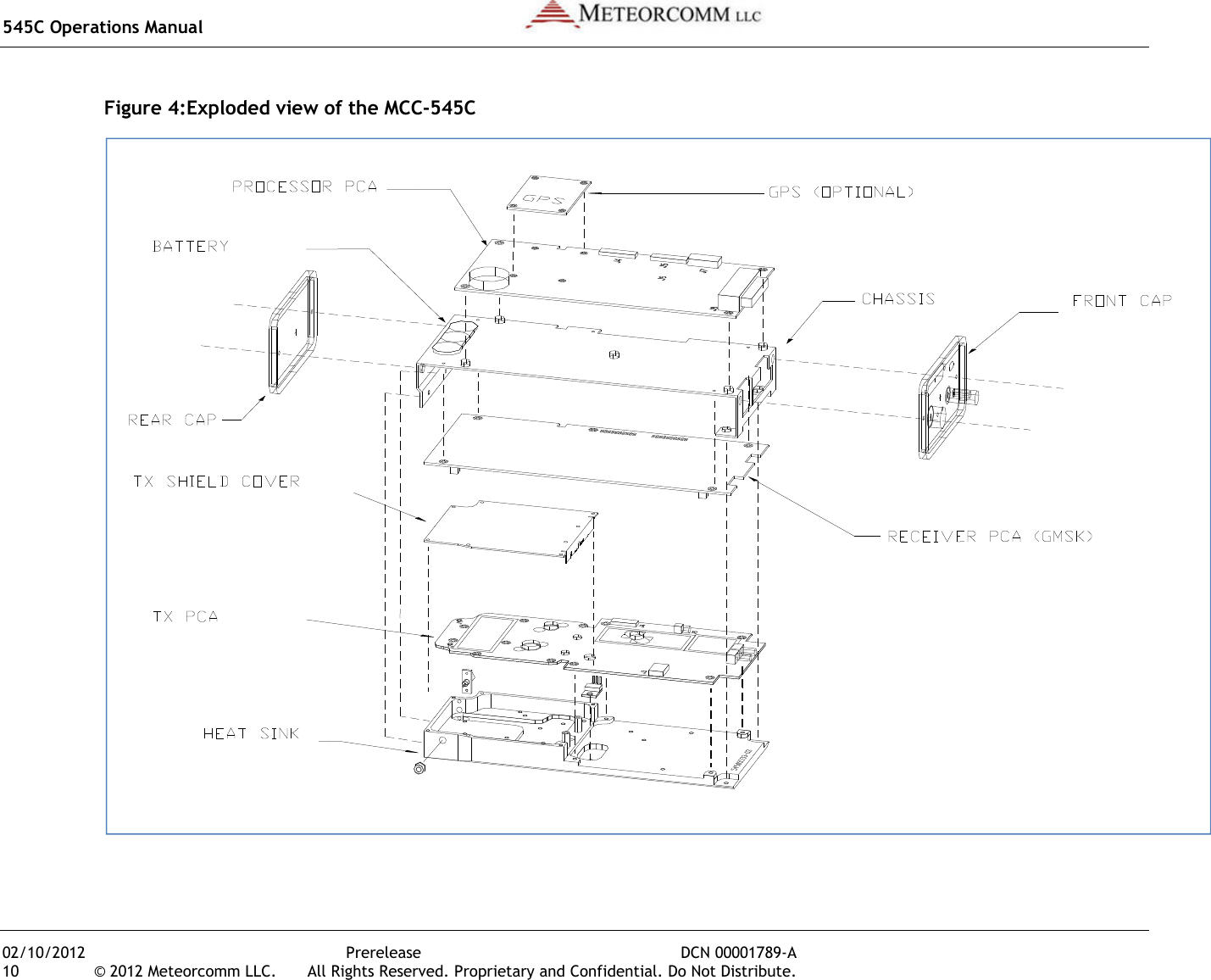
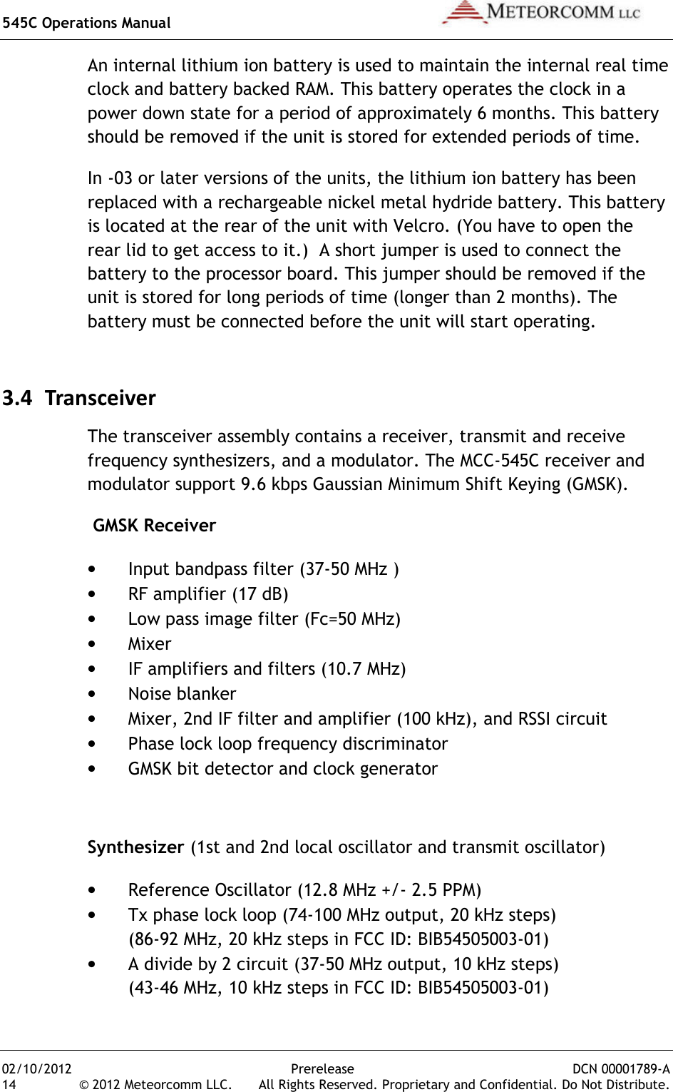
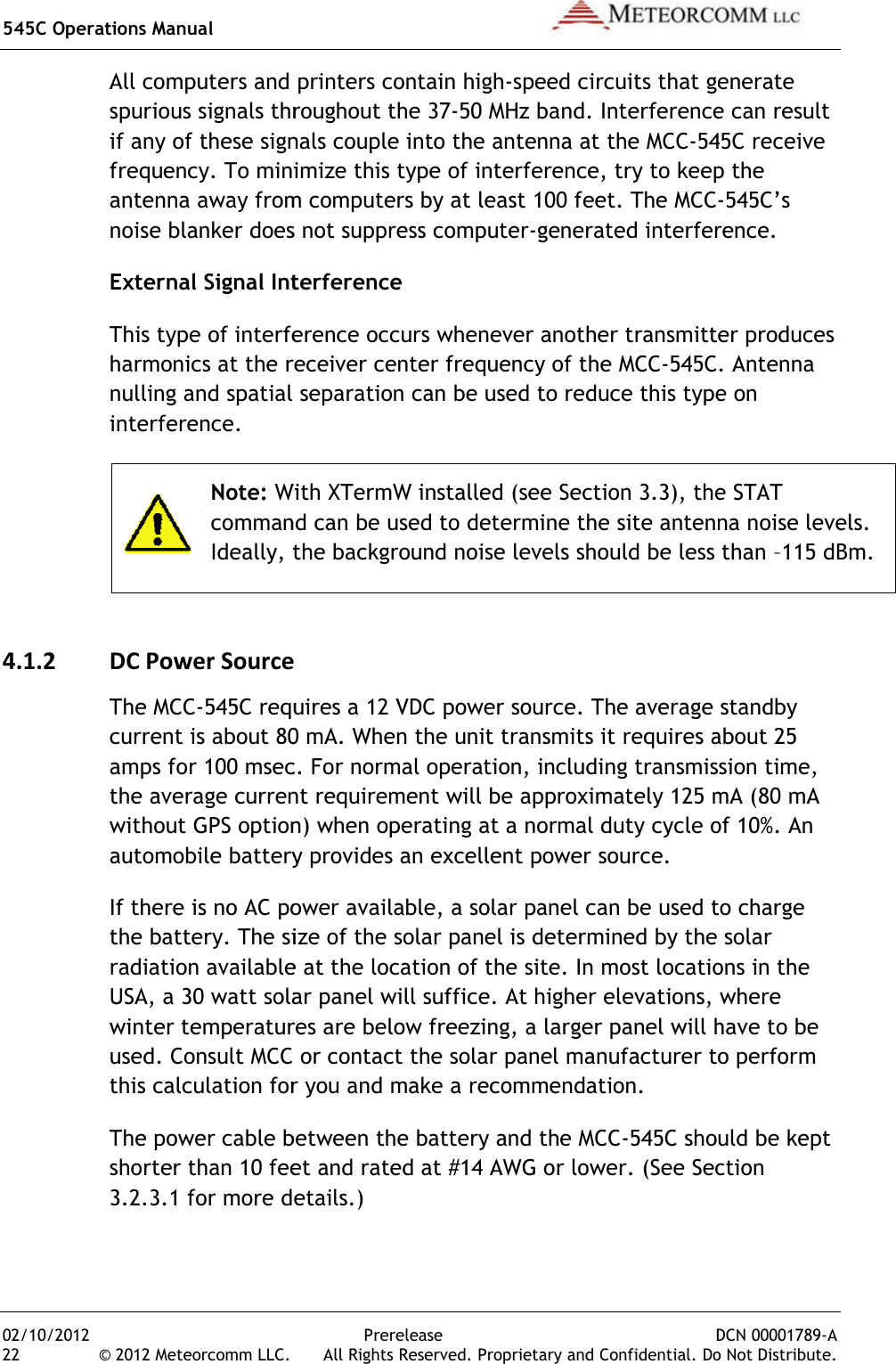
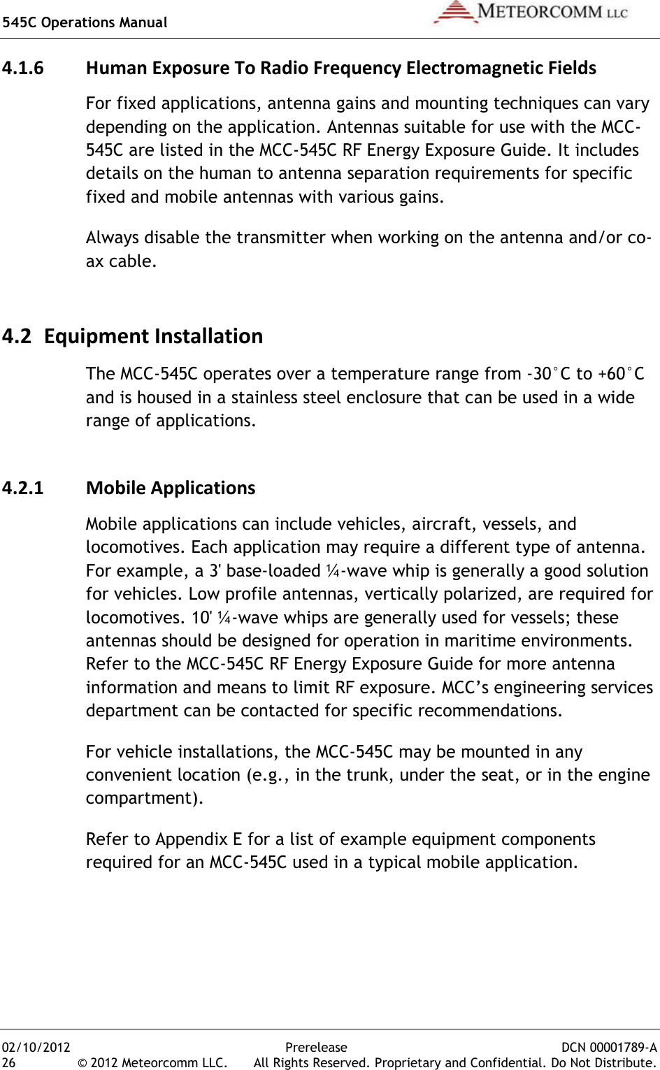

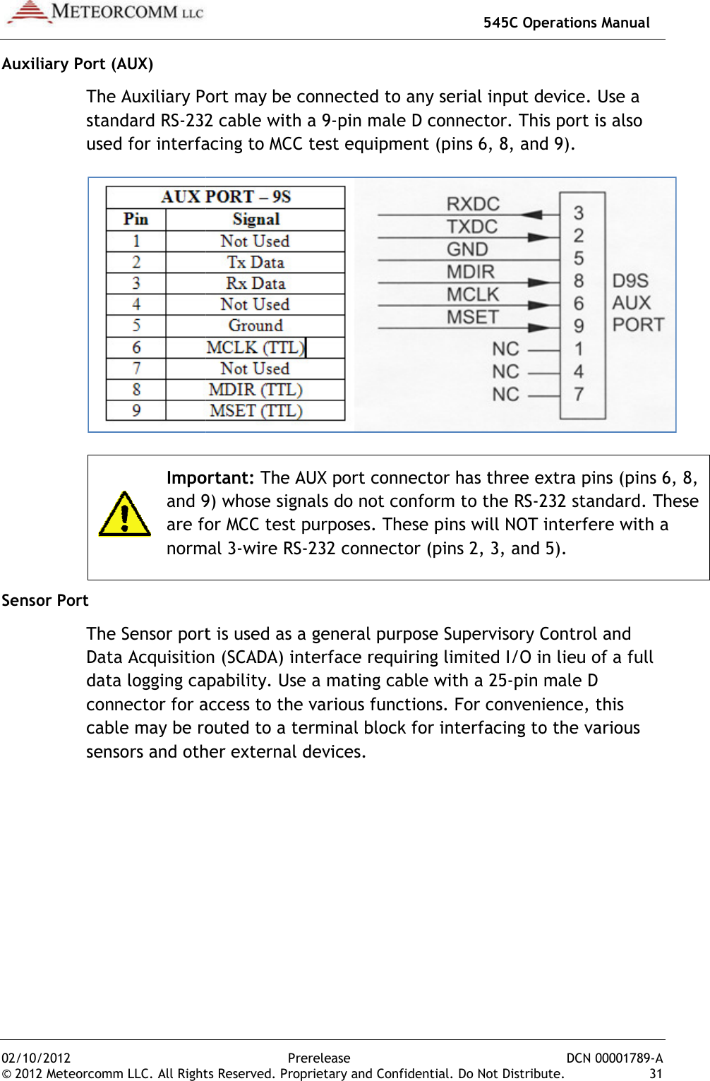
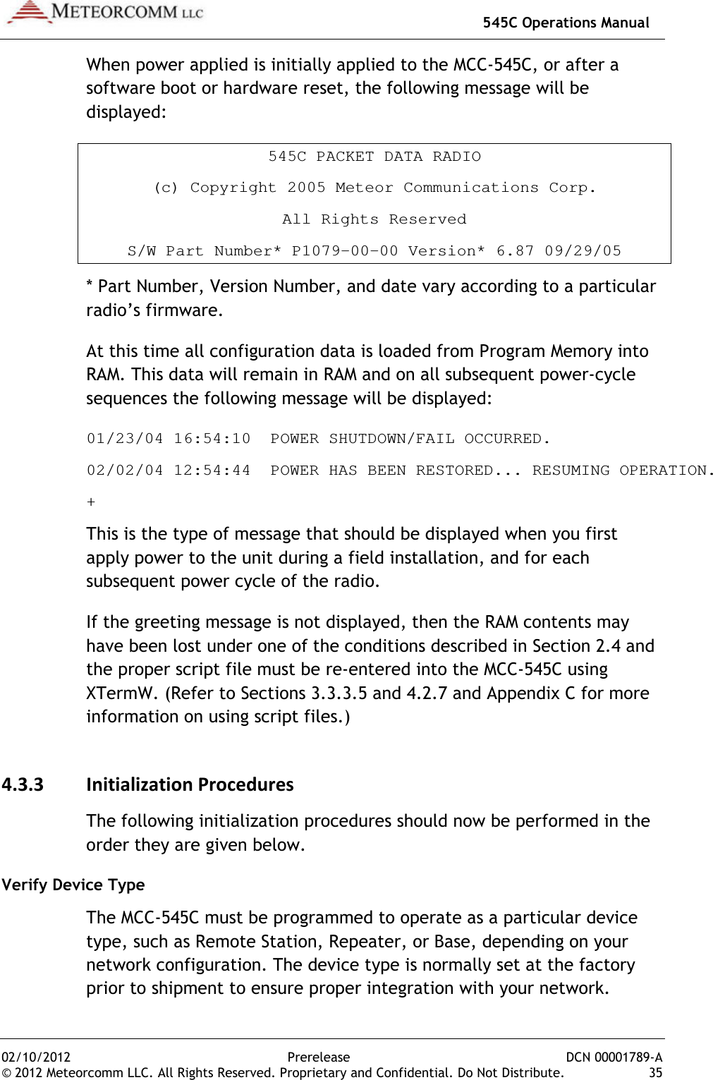
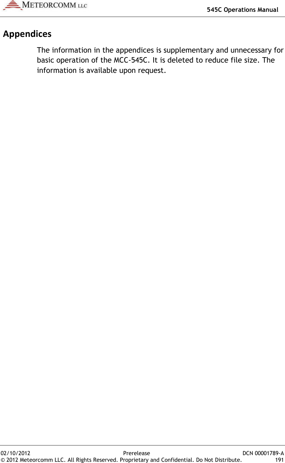
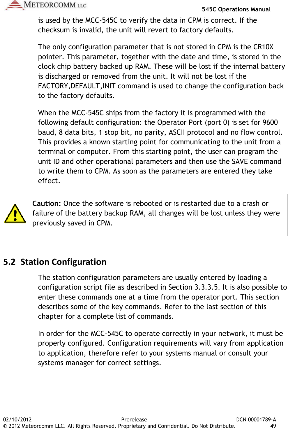
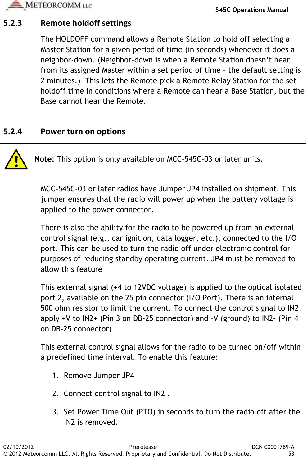
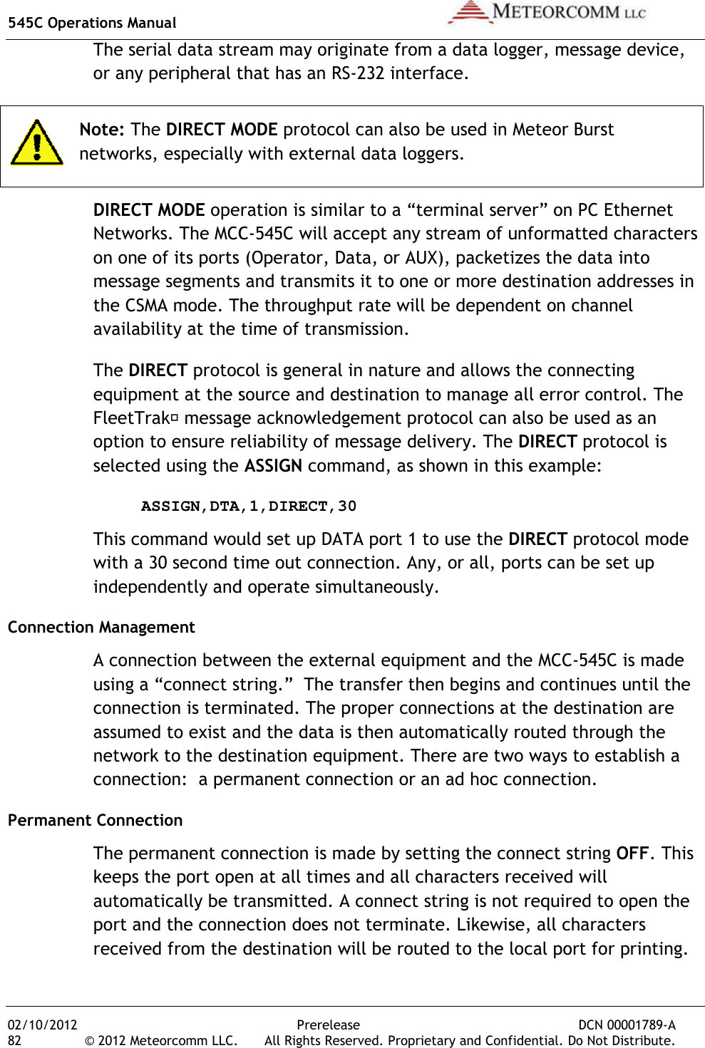
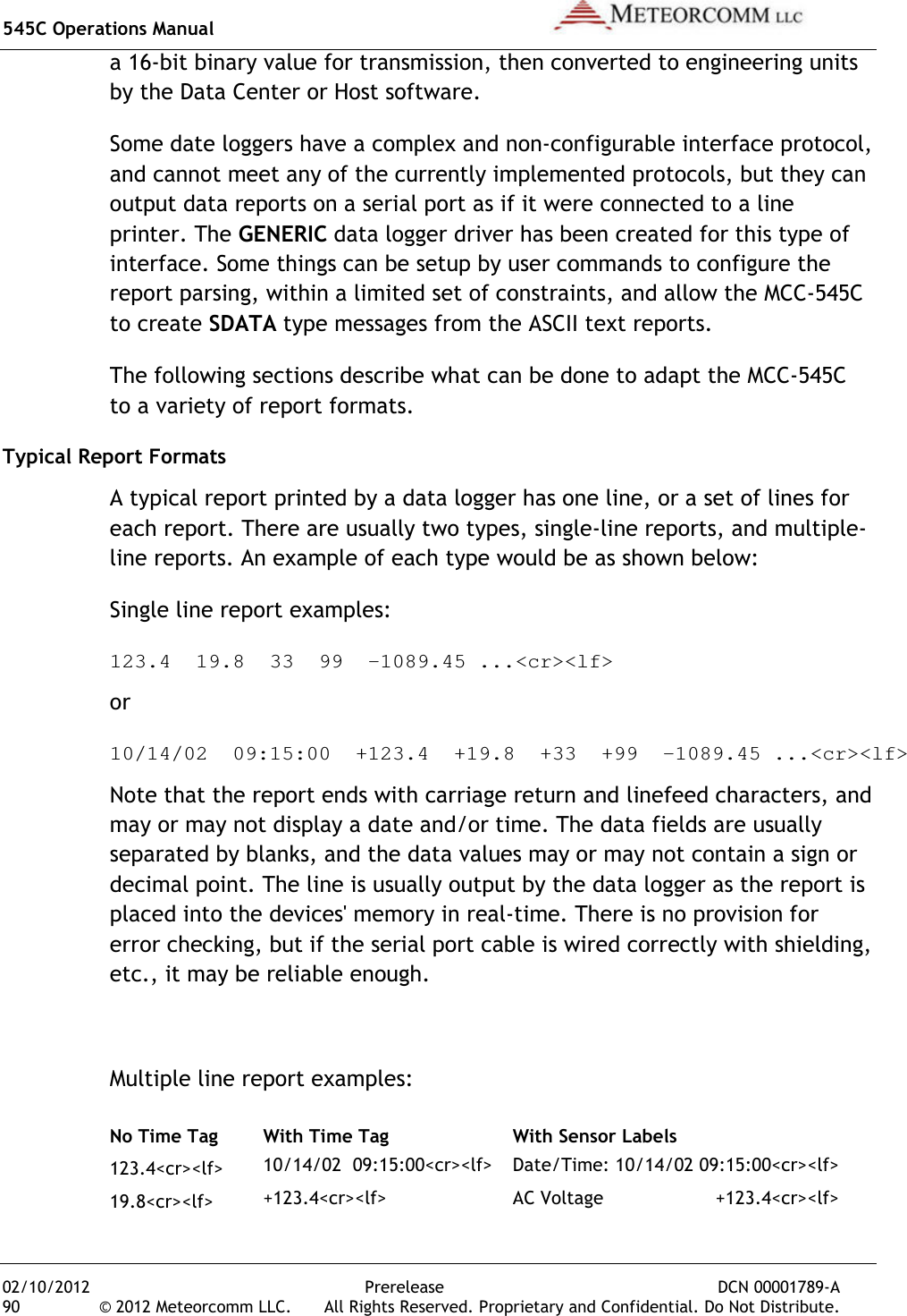
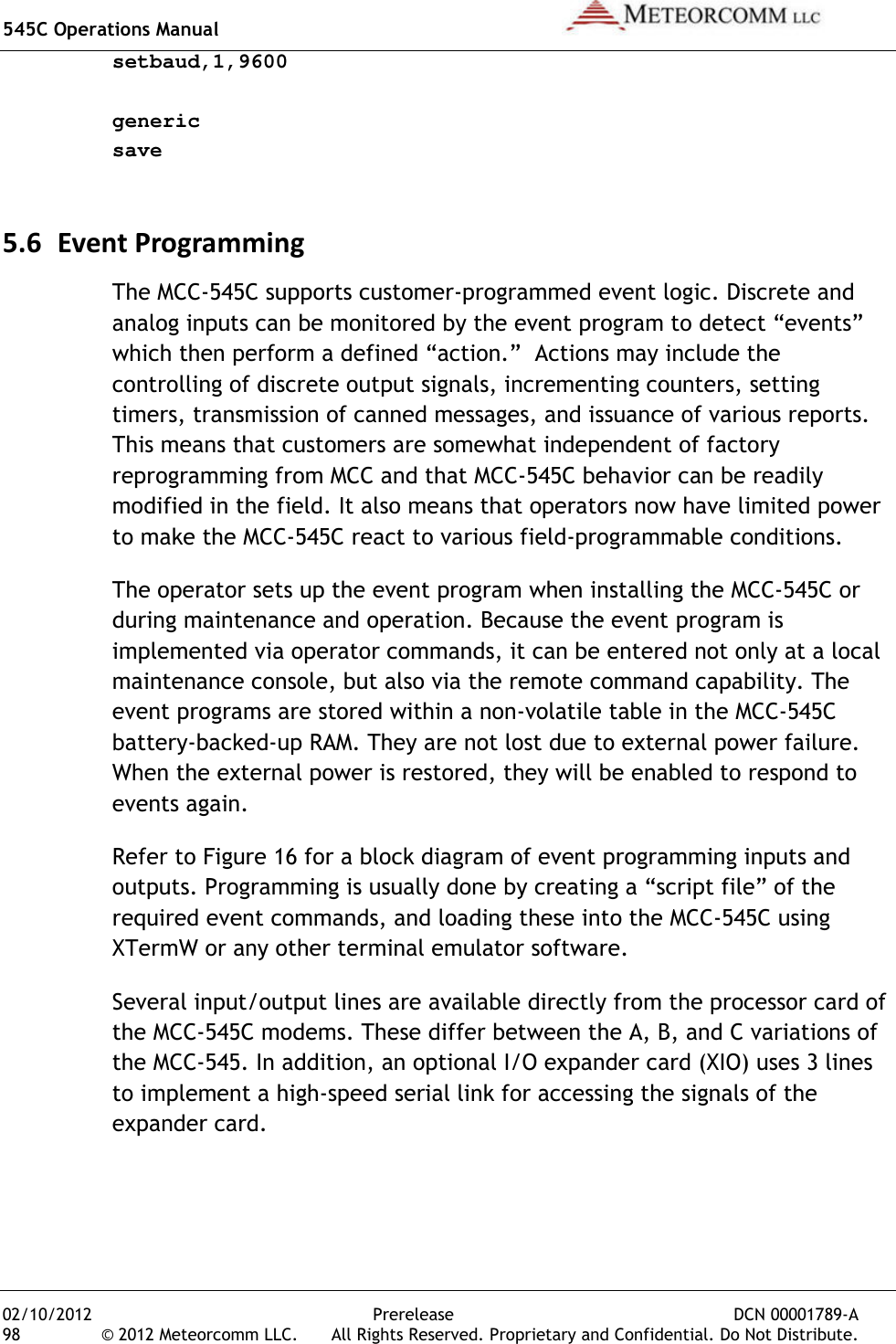
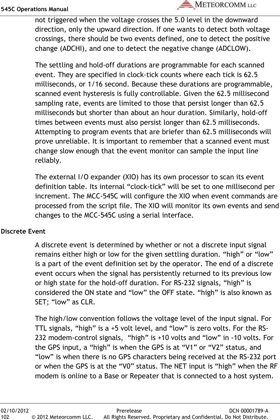
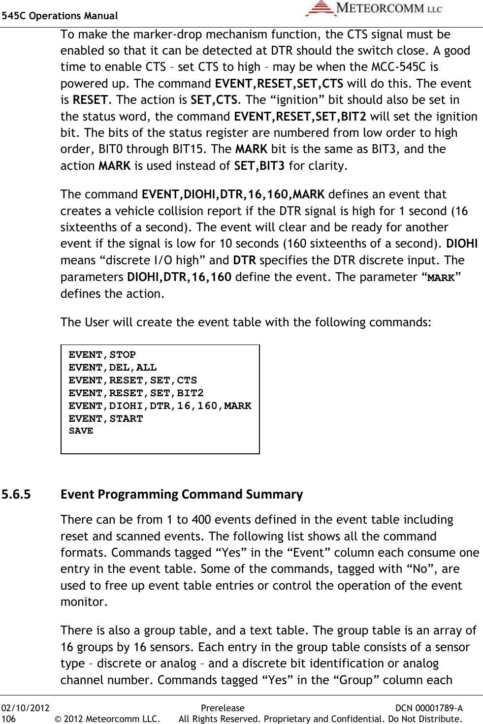
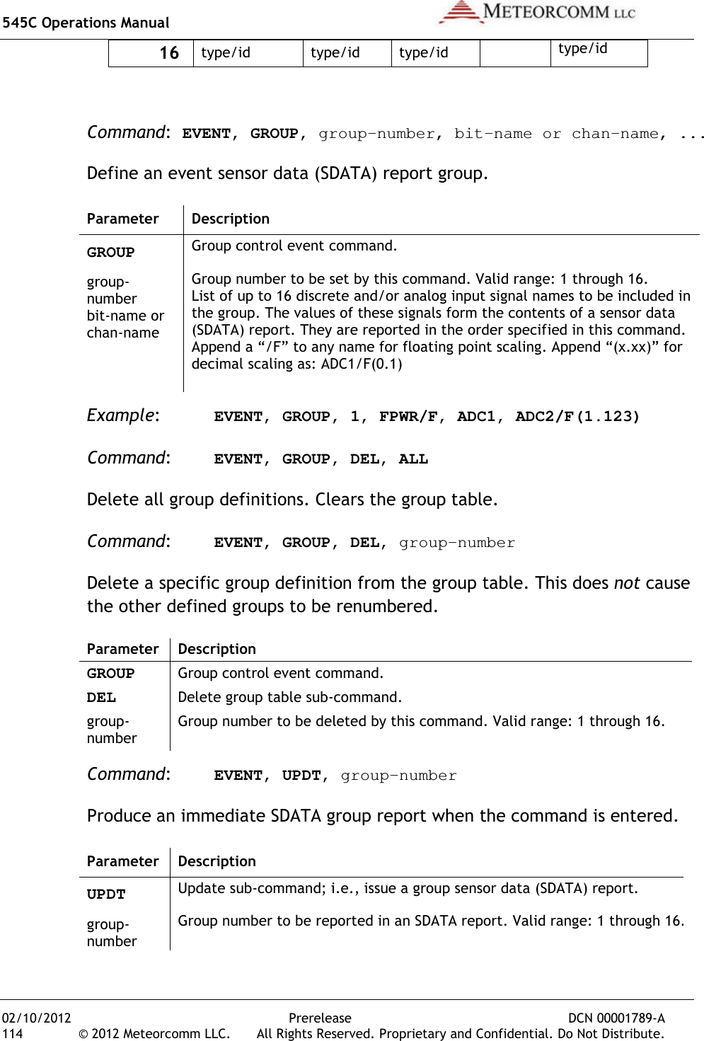
![545C Operations Manual 02/10/2012 36 © 2012 Meteorcomm LLC. Use the following command to display what device type the unit is configured as: DEVICE [ENTER] Always check with your System Administrator to determine which device type your unit should be configured as.For example, if the device should be a Remote Station and it is not currently configured properly, you can change the device type, as follows: DEVICE,REMOTE [ENTER]SAVE [ENTER] Caution: Do not change the device type uAdministrator. Changing the device type can make your unit cease operating and can impact communications throughout the entire network.Verify ID Number Every MCC unit is programmed at the factory with a 16display the unit ID number on the operator terminal, enter:ID [ENTER] Contact your System Administrator to make sure this ID is registered in the network configuration databasemay have to be changed onlocked. Caution: ID changes must be coordinated with both MCC and your System Administrator. Failure to do so may result in data or messages being misrouted or lost. Refer to Section 4.1.4.1 for more information on unit ID settings. Verify Frequency The MCC-545C is programmed at the factory with the authorized frequencies to be used in your networkParameter memory and cannot be changedfrequency is configured by enterPrerelease DCN . All Rights Reserved. Proprietary and Confidential. DoUse the following command to display what device type the unit is Always check with your System Administrator to determine which device your unit should be configured as. For example, if the device should be a Remote Station and it is not currently configured properly, you can change the device type, as DEVICE,REMOTE [ENTER] Do not change the device type unless told to do so by your System Administrator. Changing the device type can make your unit cease operating and can impact communications throughout the entire network.Every MCC unit is programmed at the factory with a 16-bit unit IDdisplay the unit ID number on the operator terminal, enter: Contact your System Administrator to make sure this ID is registered in the network configuration database. Under some circumstances the ID may have to be changed on-site. This can only be done if the ID is not ID changes must be coordinated with both MCC and your System Administrator. Failure to do so may result in data or messages being misrouted or lost. Refer to Section 4.1.4.1 for more information on unit ID 545C is programmed at the factory with the authorized frequencies to be used in your network. These frequencies are stored in Parameter memory and cannot be changed. Verify that the correct frequency is configured by entering the command: DCN 00001789-A Do Not Distribute. Use the following command to display what device type the unit is Always check with your System Administrator to determine which device For example, if the device should be a Remote Station and it is not currently configured properly, you can change the device type, as nless told to do so by your System Administrator. Changing the device type can make your unit cease operating and can impact communications throughout the entire network. bit unit ID. To Contact your System Administrator to make sure this ID is registered in Under some circumstances the ID nly be done if the ID is not ID changes must be coordinated with both MCC and your System Administrator. Failure to do so may result in data or messages being misrouted or lost. Refer to Section 4.1.4.1 for more information on unit ID 545C is programmed at the factory with the authorized These frequencies are stored in Verify that the correct](https://usermanual.wiki/Meteorcomm/54505003-01.Users-Manual/User-Guide-1643156-Page-46.png)
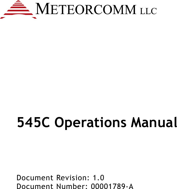
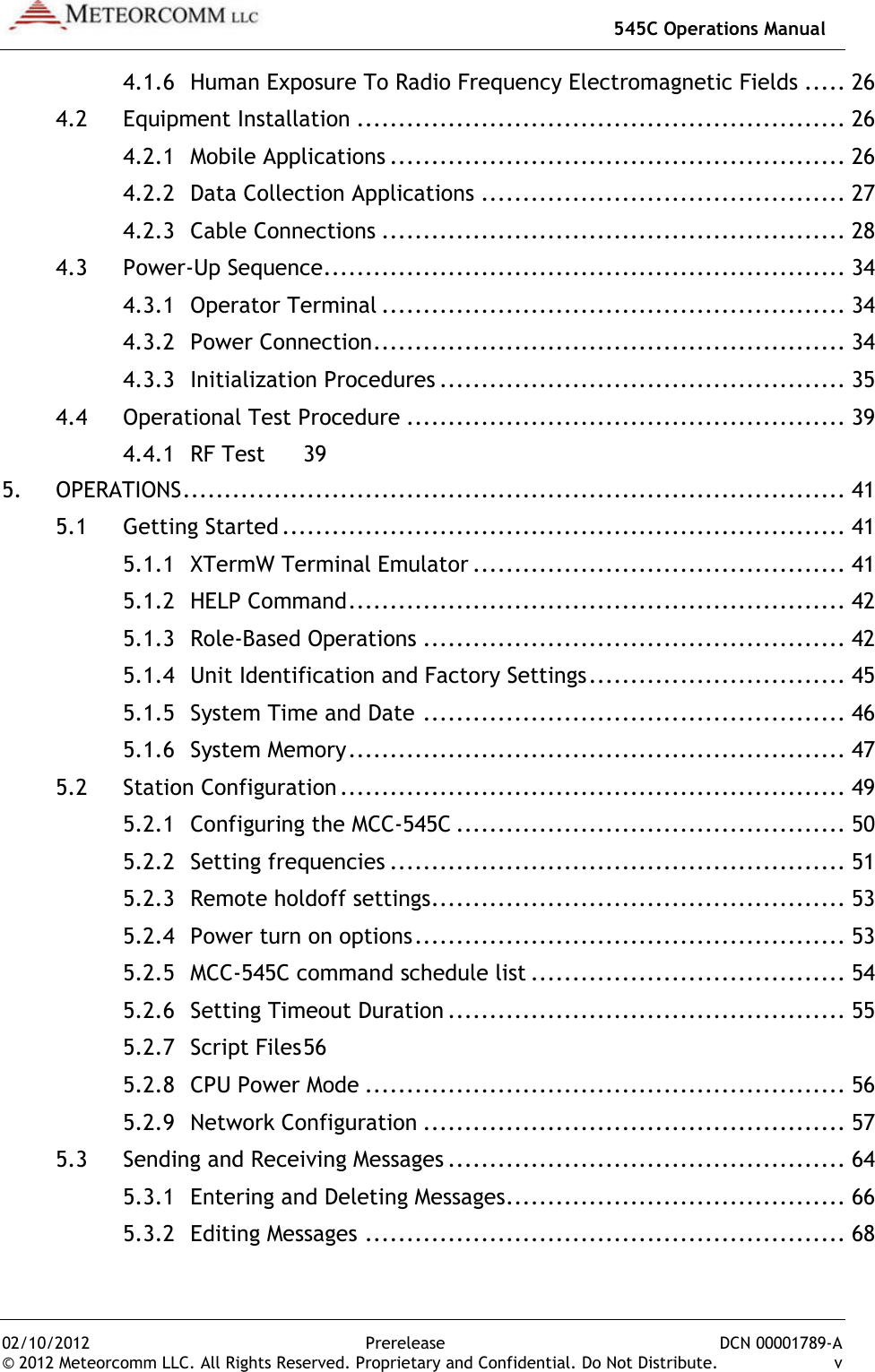
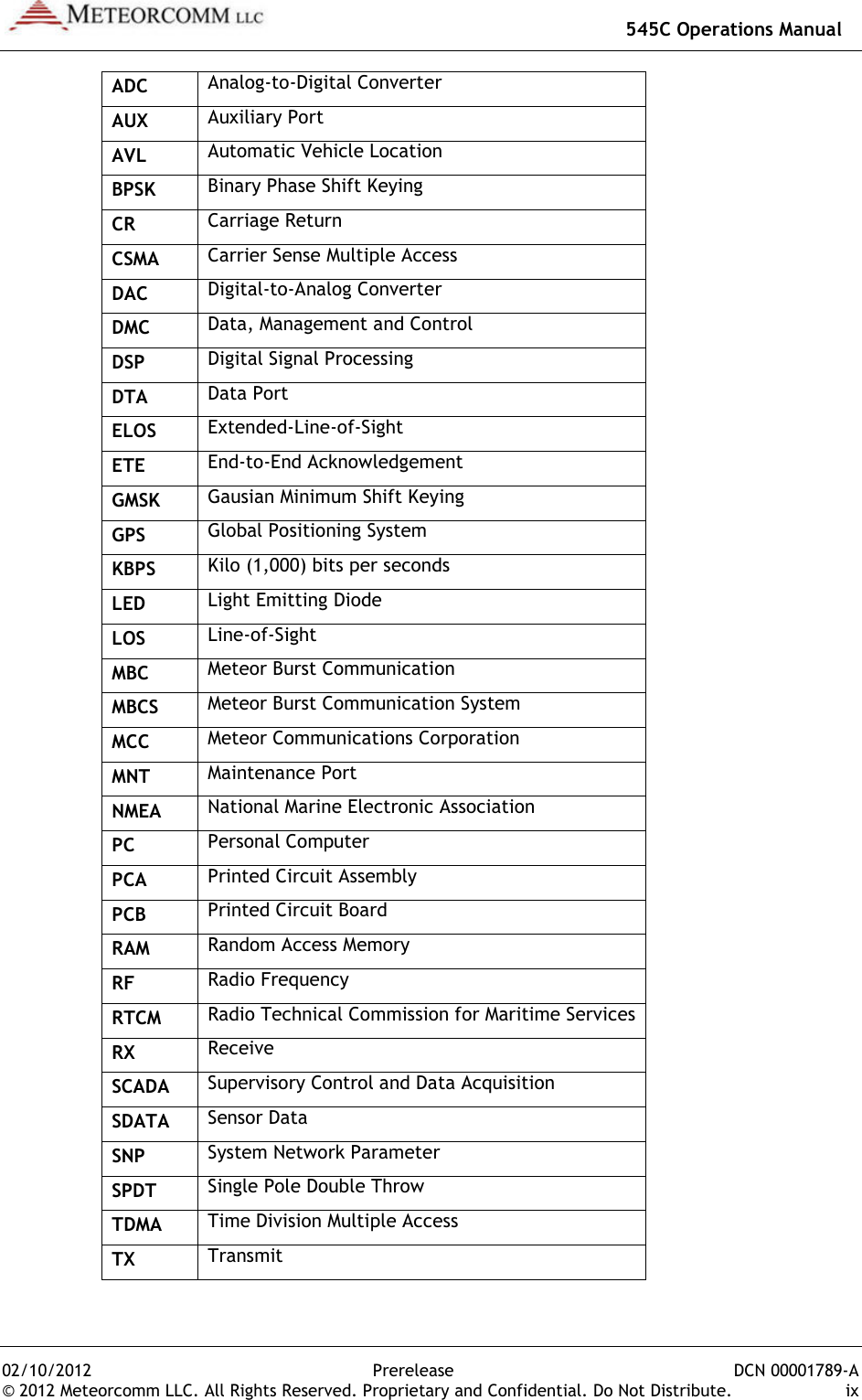
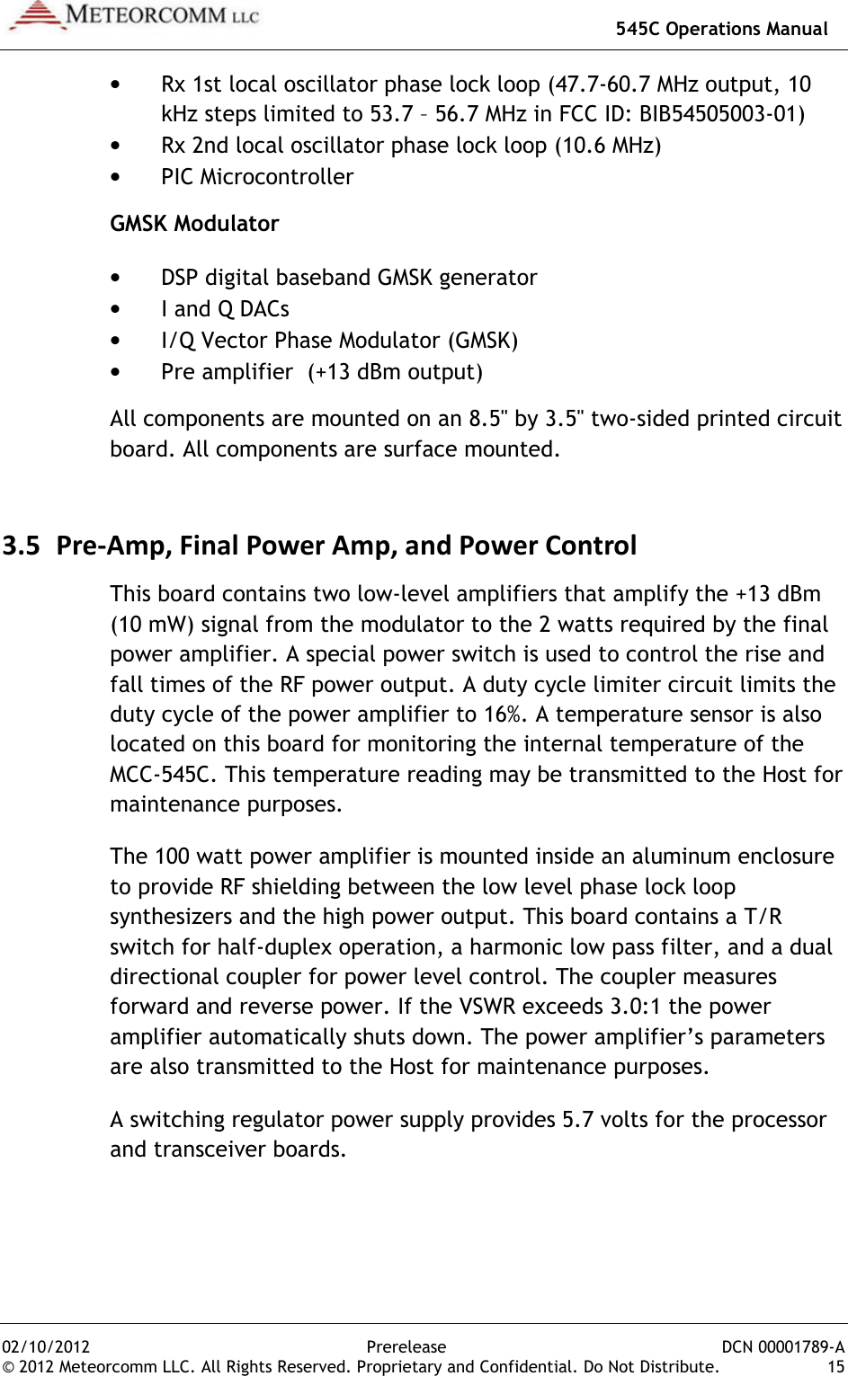
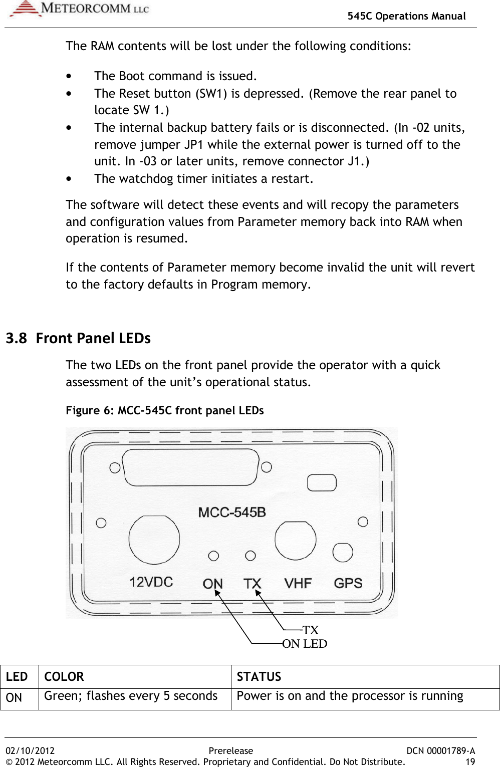
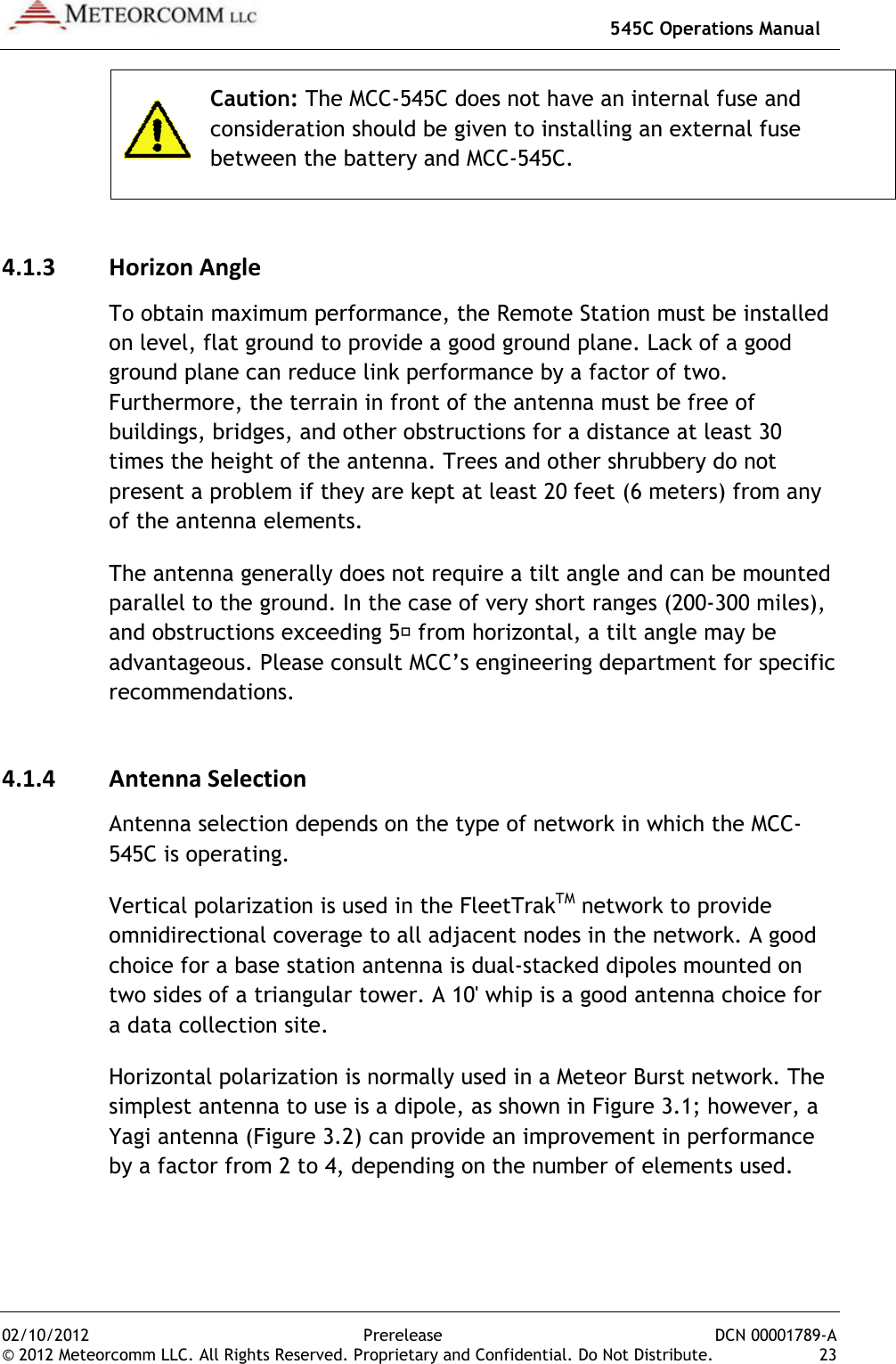
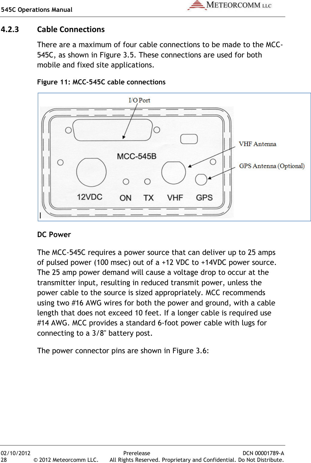
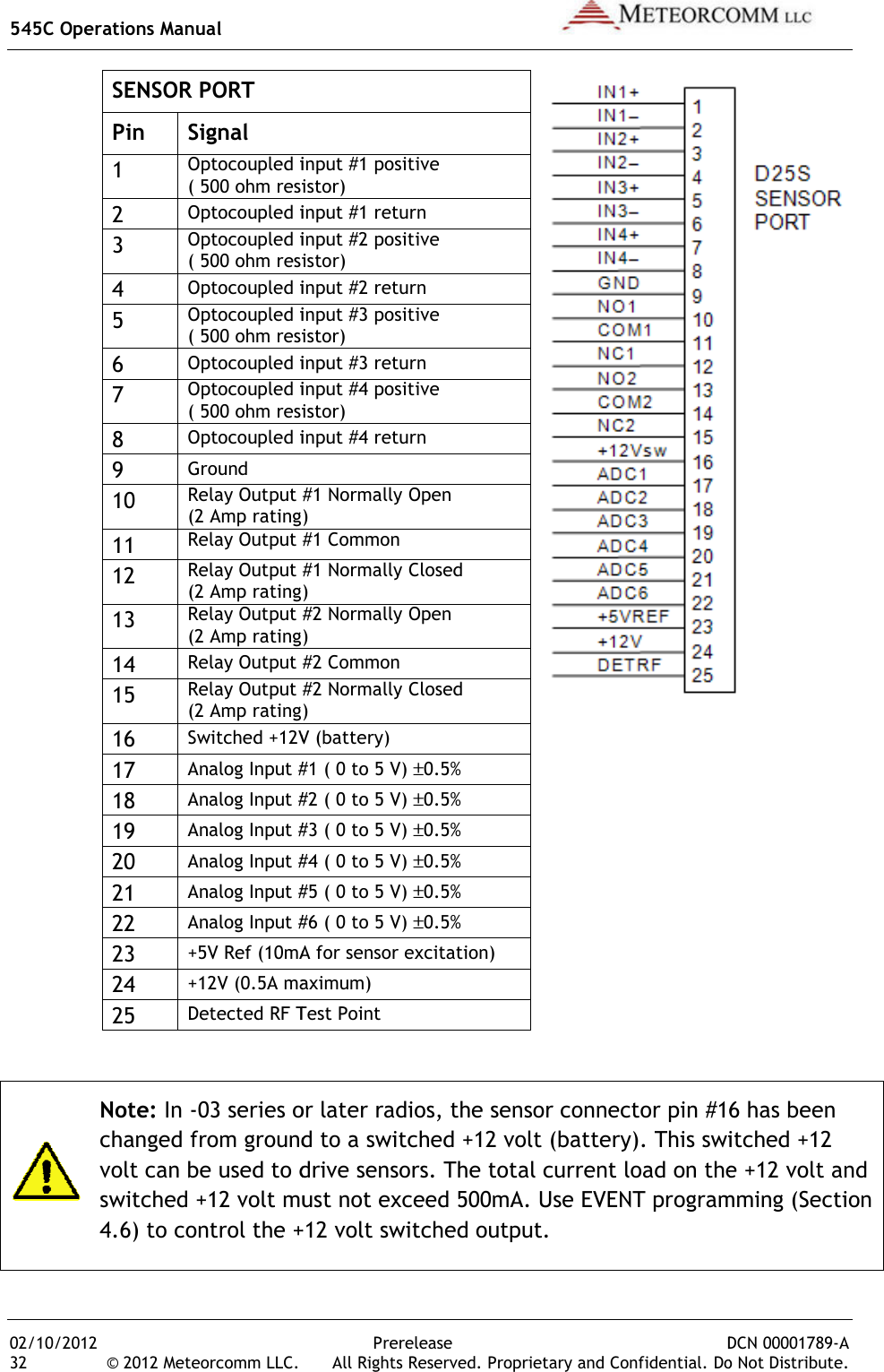
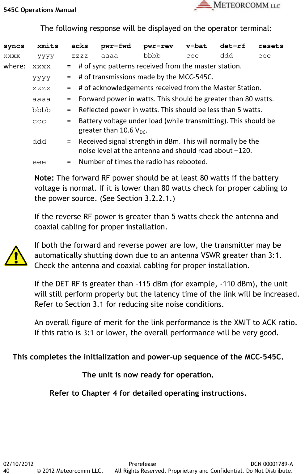
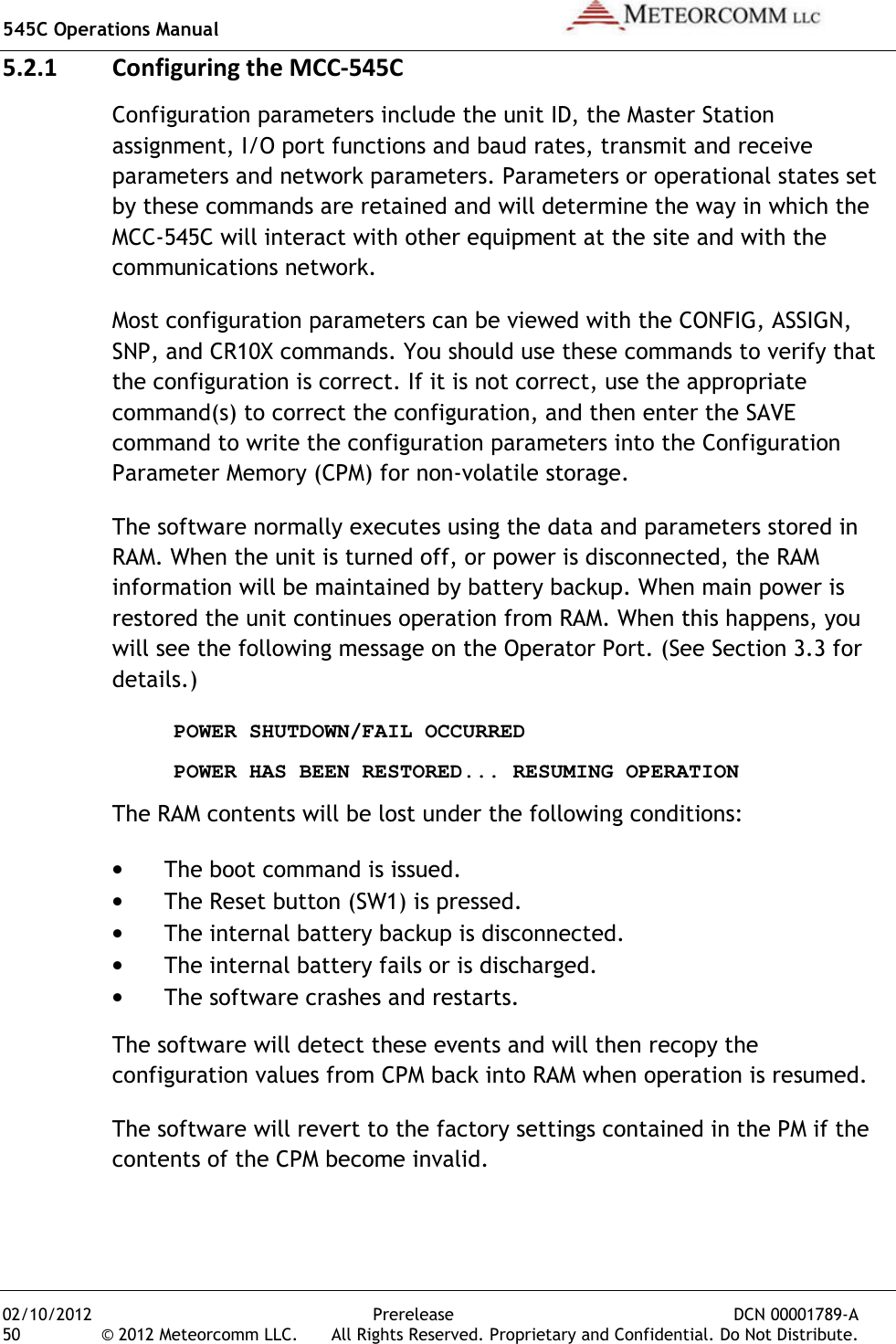
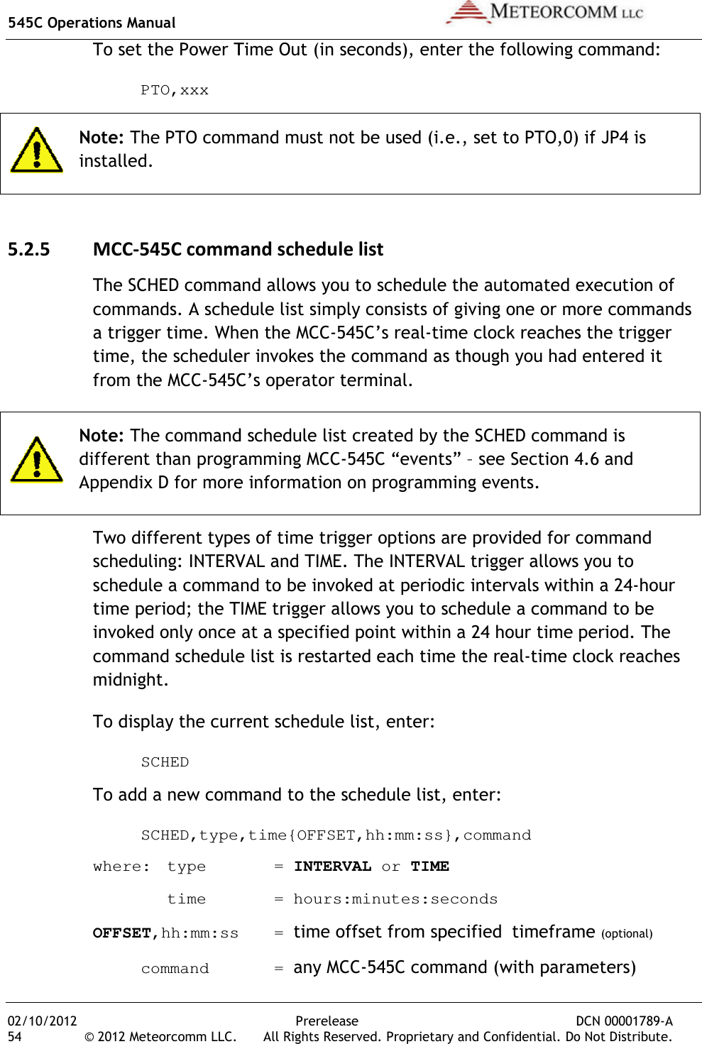
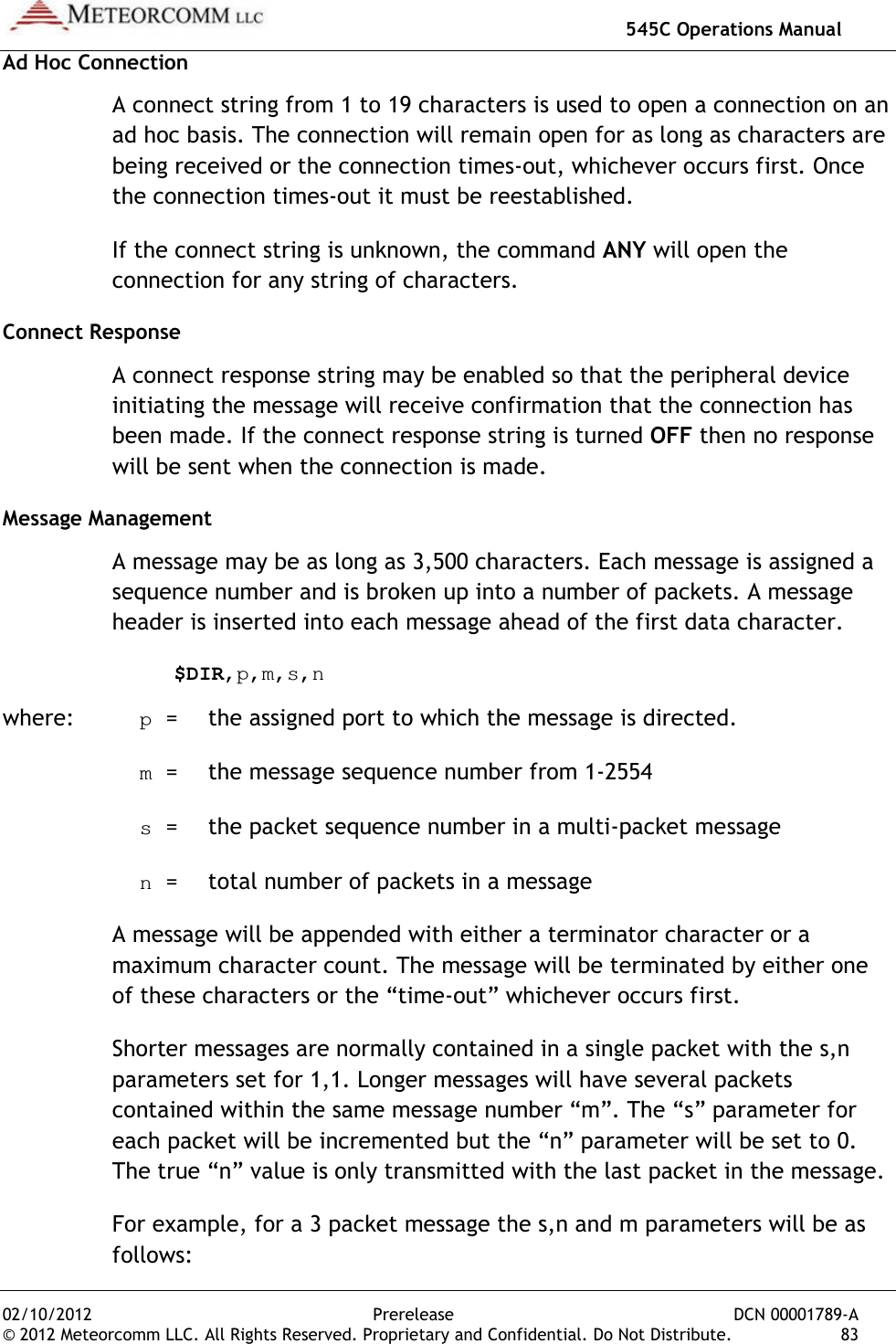
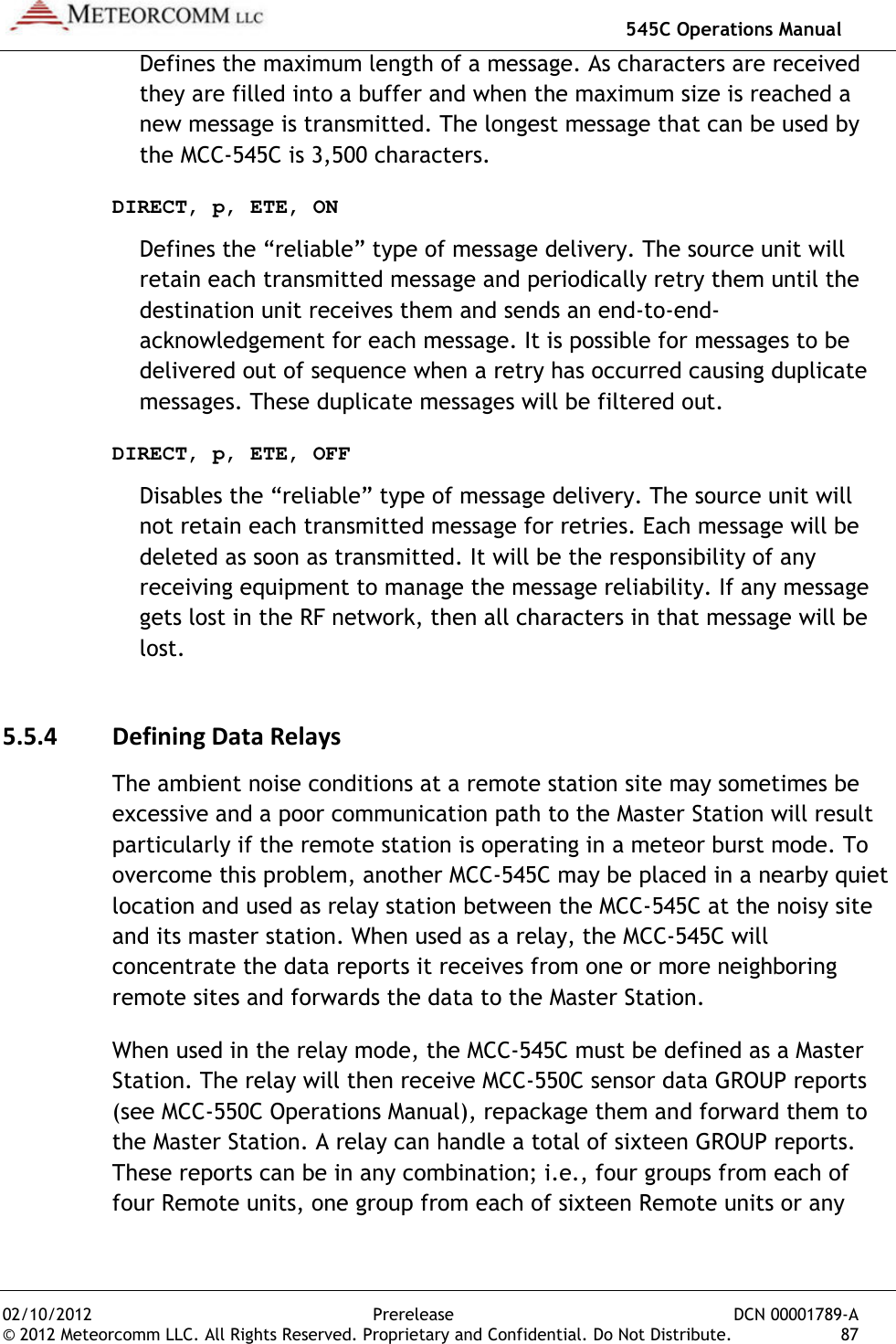
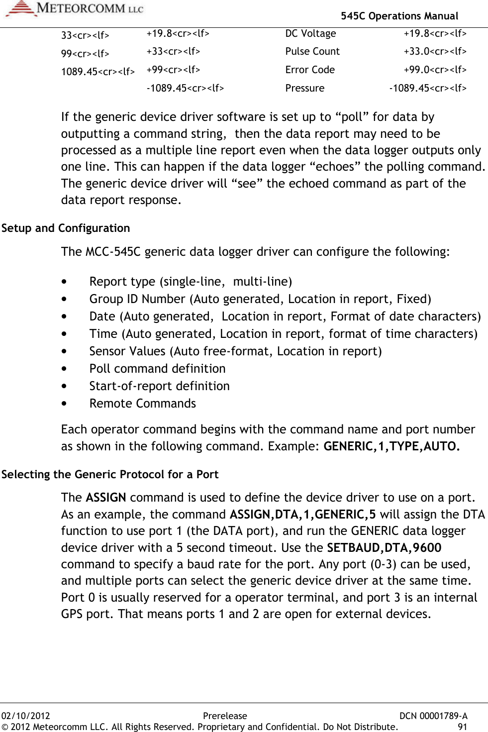
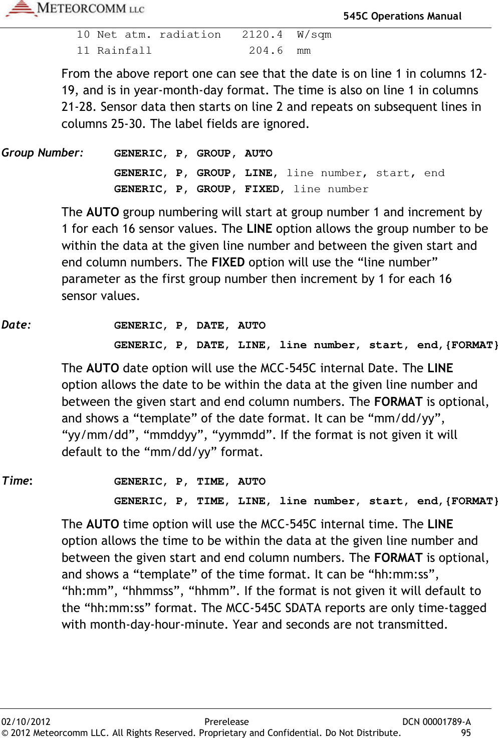
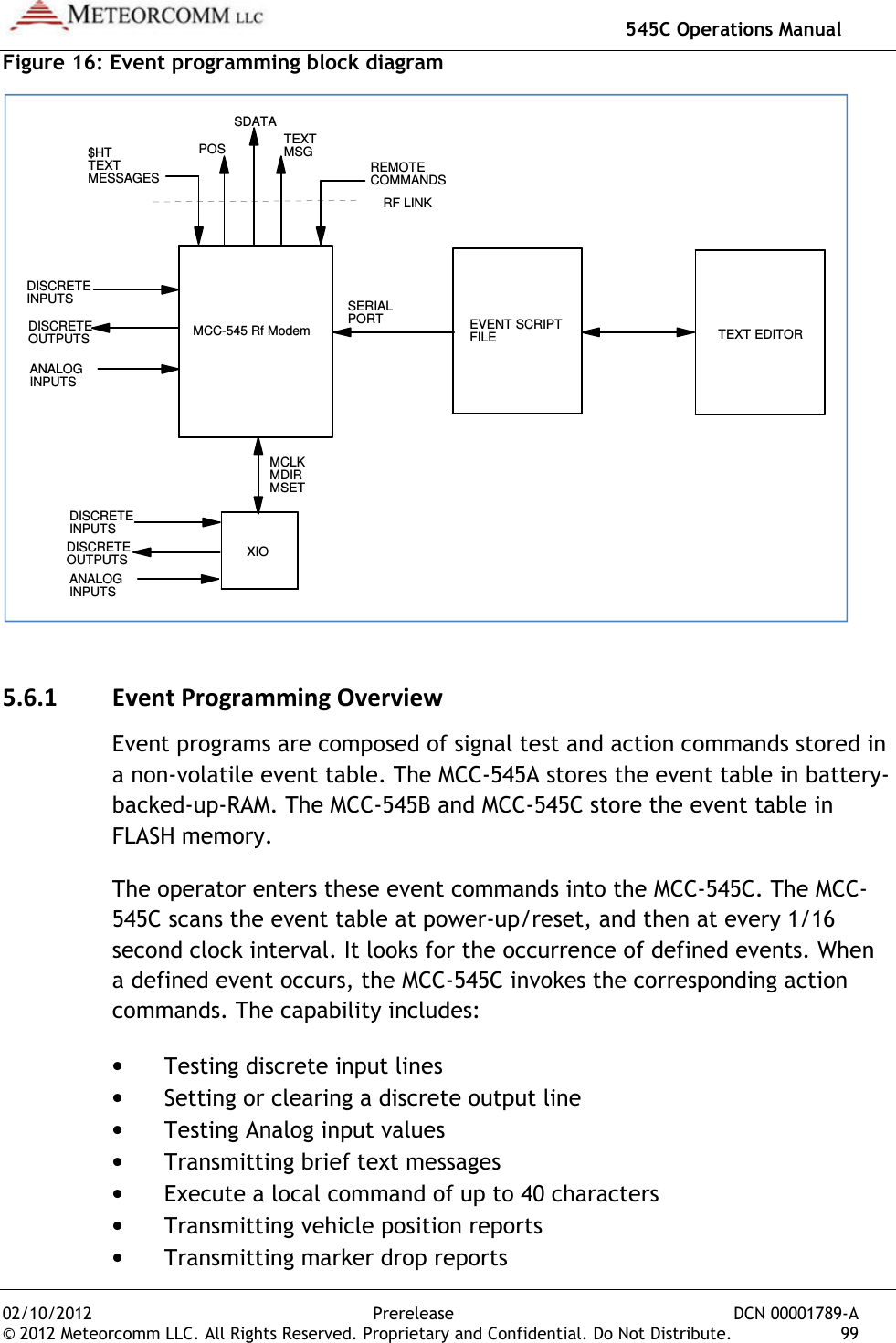
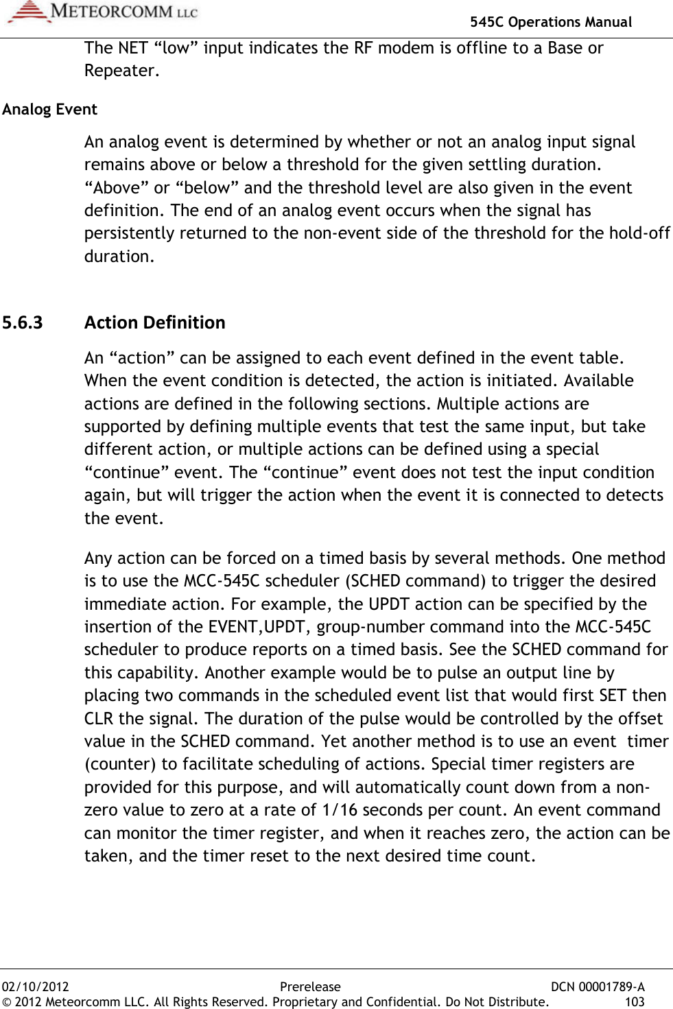
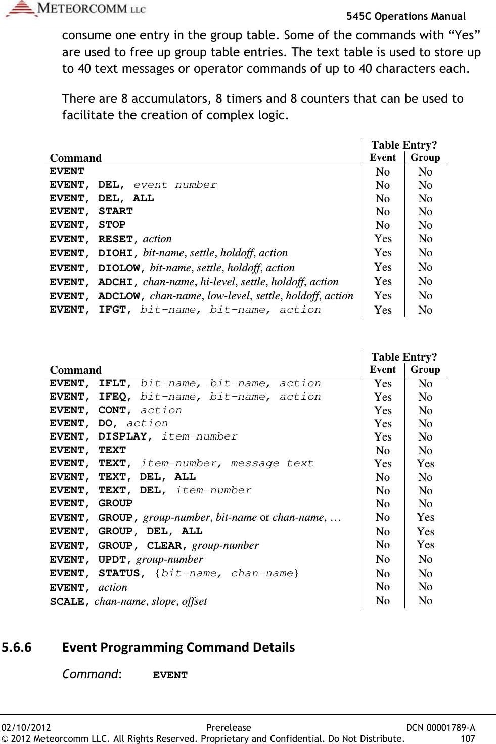
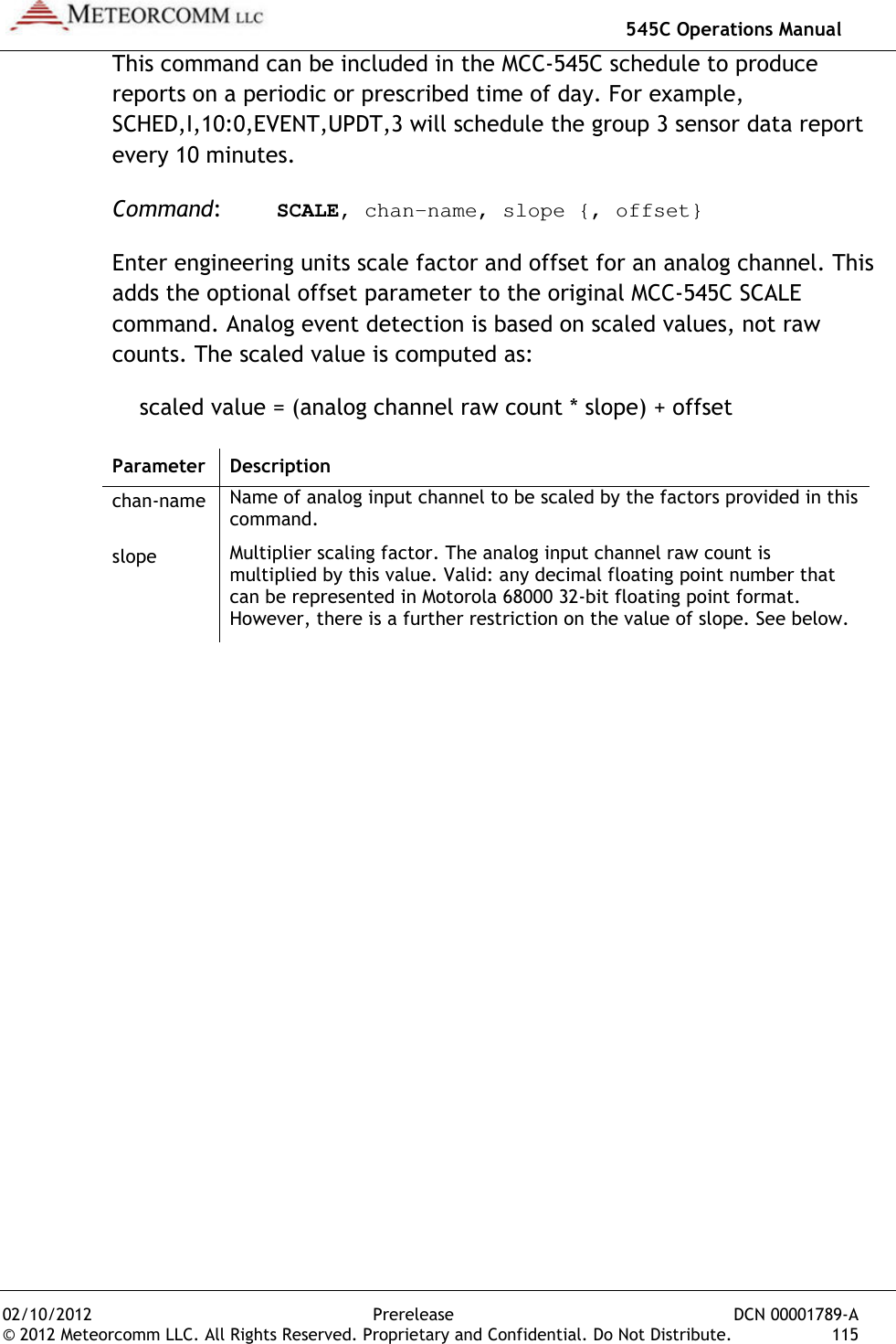
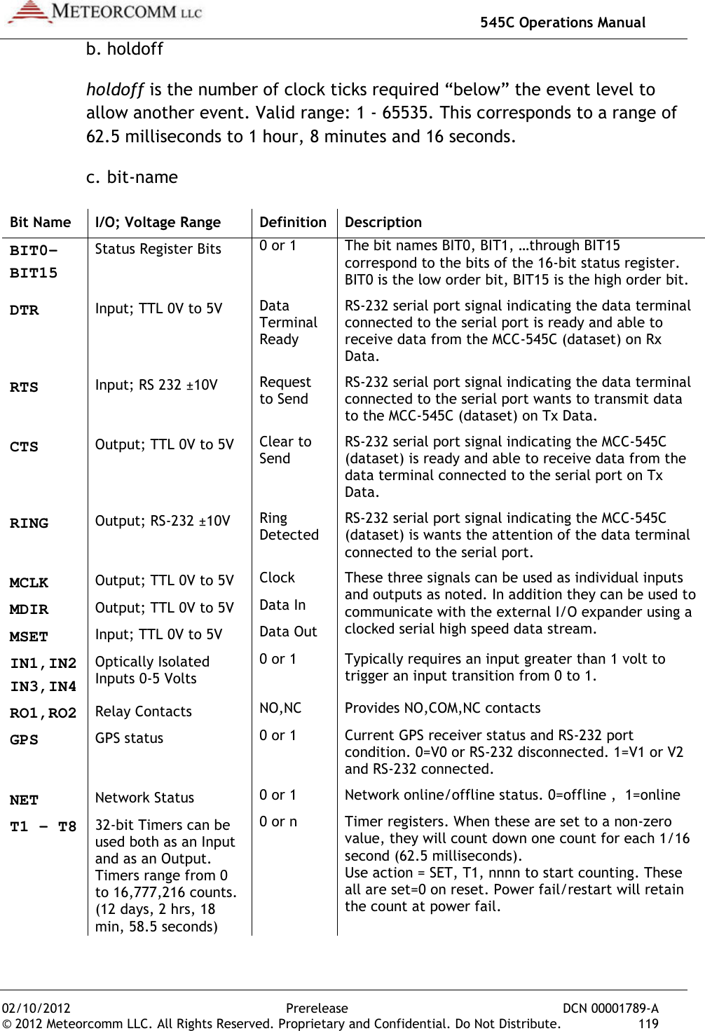
![02/10/2012 © 2012 Meteorcomm LLC. All RightFREQUENCIES [ENTER]or FREQ [ENTER] This shows you the active or “primary” TX and RX frequency pair, plus up to 9 additional frequency pairs for channels that may be programmed at the factory.For example, the following +freq 05/18/04 08:53:50 Primary TX 044.58 MHz RX 044.58 MHzFrequency TableChannel >00* 01 02 03 04 05 06 07 08 09 Caution: Do not change the frequency pair unless told to do so by your System Administrator. Changing the frequency pair can communicating with the network.Once the frequencies are verified, confirm that the synthesizer is “ON” and locked by entering the following command: SYNTHESIZER [ENTER] or SYNTH [ENTER] The unit responds with:SYNTH,ON,LOCKED (or UNLOCKED)If the synthesizer returns an unlocked response, ensure that the proper frequency pair is selected. 545C Operations ManualPrerelease hts Reserved. Proprietary and Confidential. Do Not DistribuFREQUENCIES [ENTER] FREQ [ENTER] for short cut This shows you the active or “primary” TX and RX frequency pair, plus up to 9 additional frequency pairs for channels that may be programmed at the factory. For example, the following table could be displayed: +freq 05/18/04 08:53:50 Primary TX 044.58 MHz RX 044.58 MHzFrequency Table TX RX 044.58 MHz 044.58 MHz045.90 MHz 044.20 MHz000.00 MHz 000.00 MHz000.00 MHz 000.00 MHz000.00 MHz 000.00 MHz000.00 MHz 000.00 MHz000.00 MHz 000.00 MHz000.00 MHz 000.00 MHz000.00 MHz 000.00 MHz000.00 MHz 000.00 MHzDo not change the frequency pair unless told to do so by your System Administrator. Changing the frequency pair can make your unit stop communicating with the network. Once the frequencies are verified, confirm that the synthesizer is “ON” and locked by entering the following command: SYNTHESIZER [ENTER] SYNTH [ENTER] for short cut The unit responds with: ,ON,LOCKED (or UNLOCKED) If the synthesizer returns an unlocked response, ensure that the proper frequency pair is selected. 545C Operations Manual DCN 00001789-A ibute. 37 This shows you the active or “primary” TX and RX frequency pair, plus up to 9 additional frequency pairs for channels that may be +freq 05/18/04 08:53:50 Primary TX 044.58 MHz RX 044.58 MHz 044.58 MHz 044.20 MHz 000.00 MHz 000.00 MHz 000.00 MHz 000.00 MHz 000.00 MHz 000.00 MHz 000.00 MHz 000.00 MHz Do not change the frequency pair unless told to do so by your make your unit stop Once the frequencies are verified, confirm that the synthesizer is “ON” If the synthesizer returns an unlocked response, ensure that the proper](https://usermanual.wiki/Meteorcomm/54505003-01.Users-Manual/User-Guide-1643156-Page-47.png)
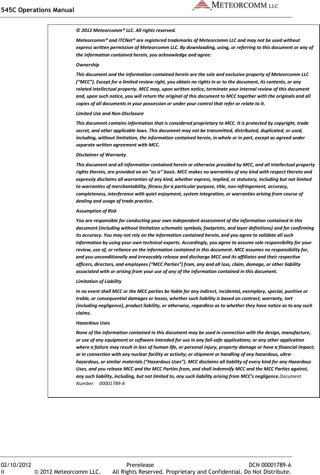
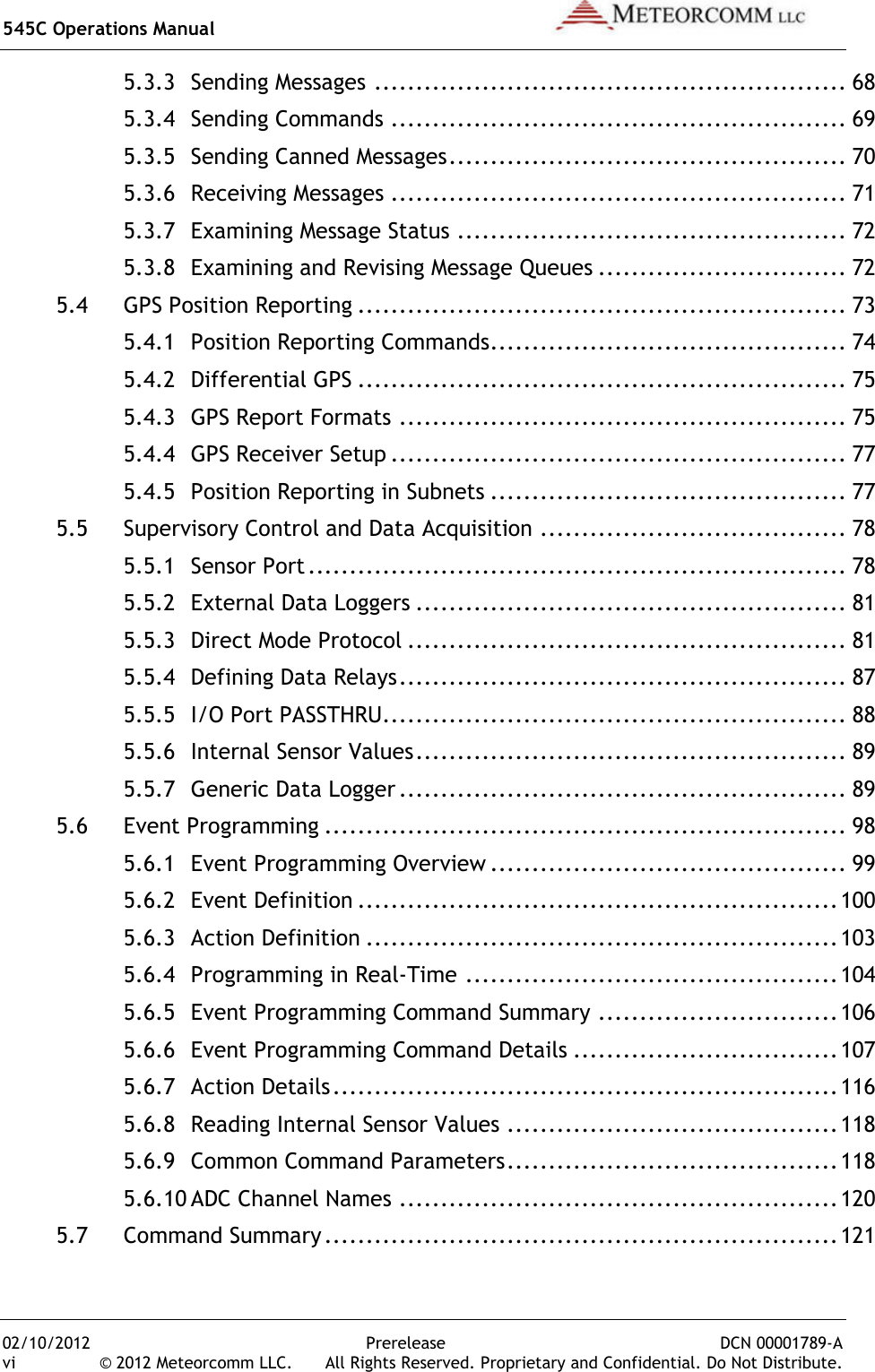
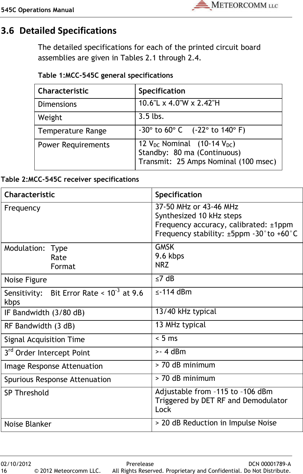
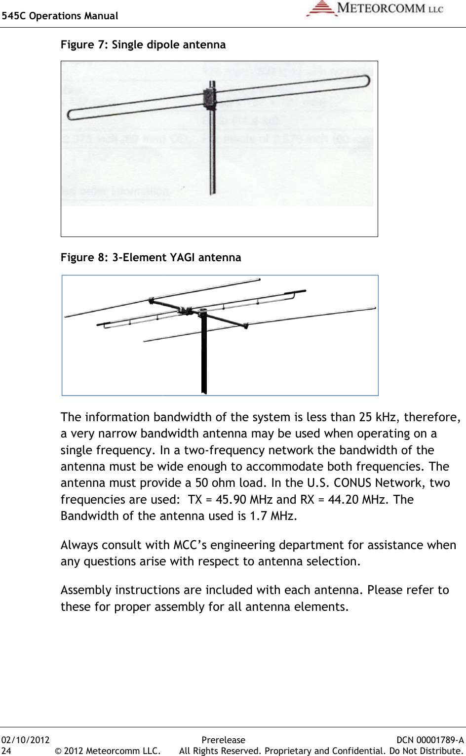
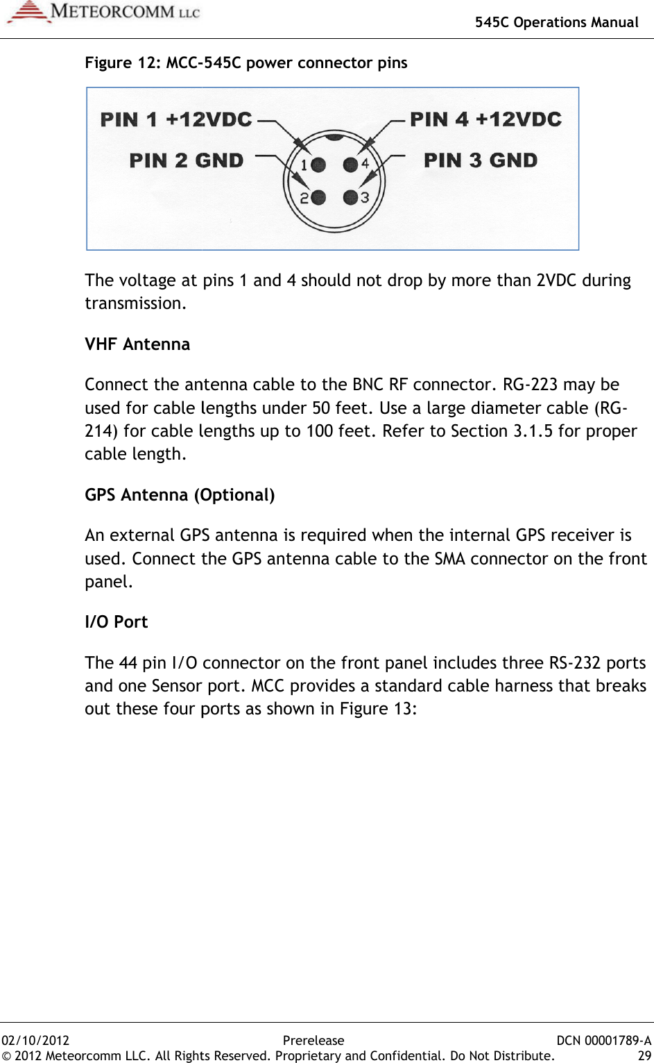
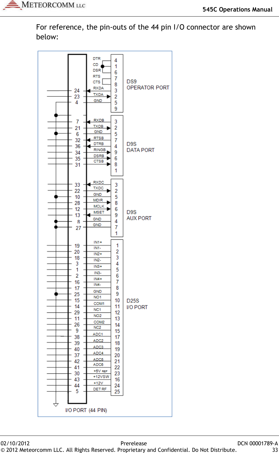
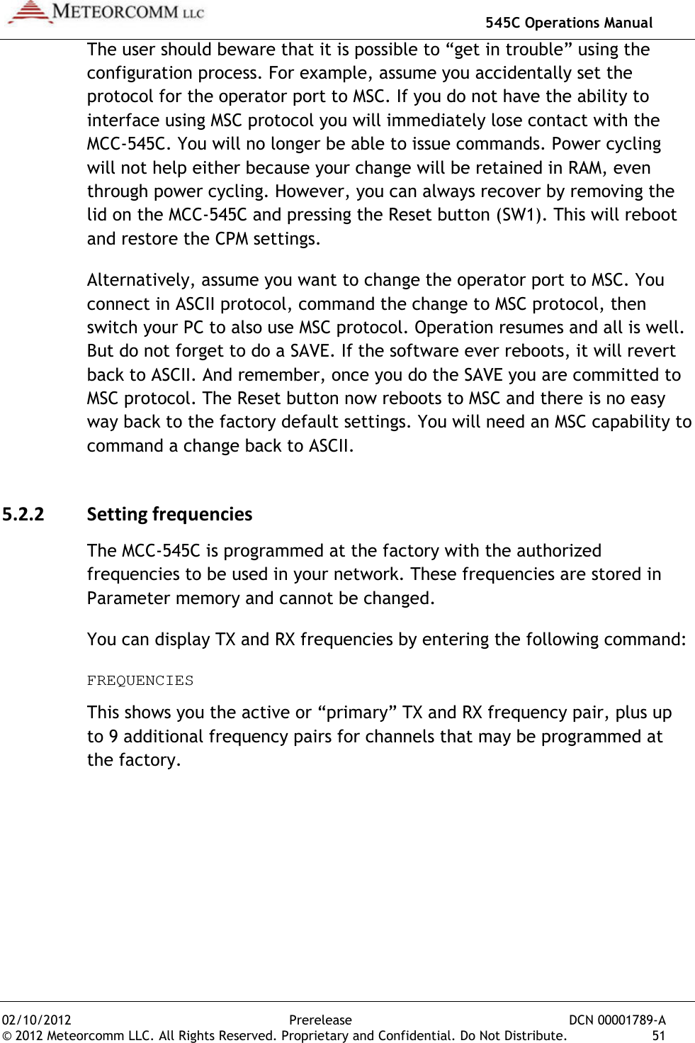
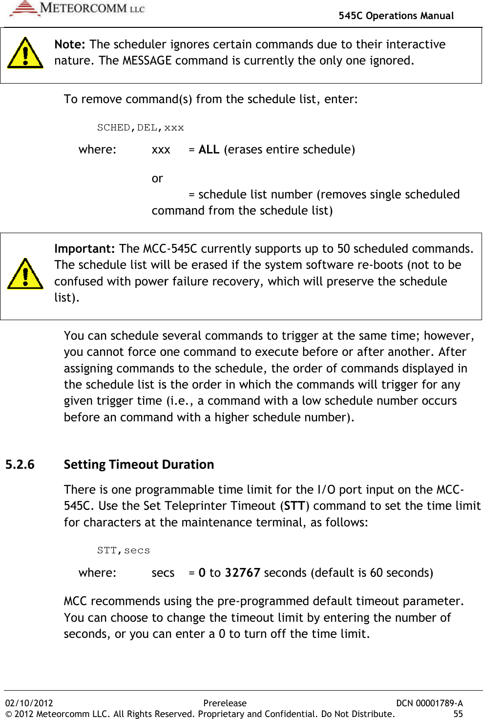
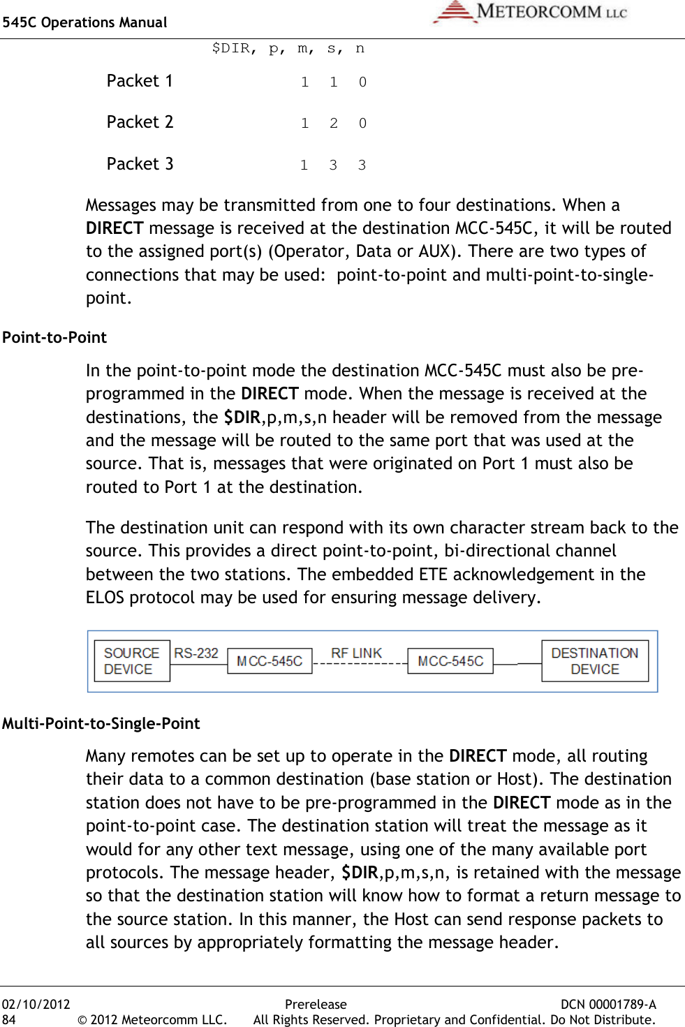
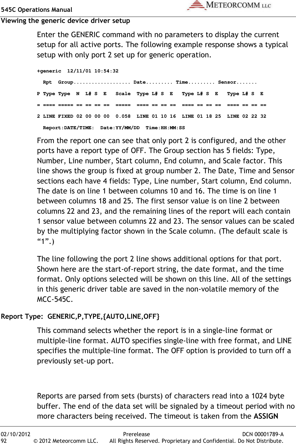
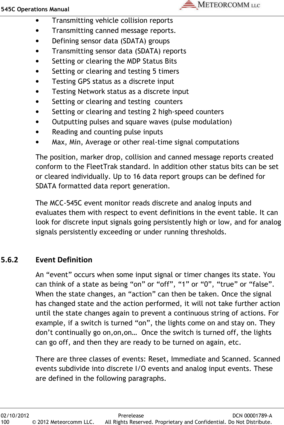
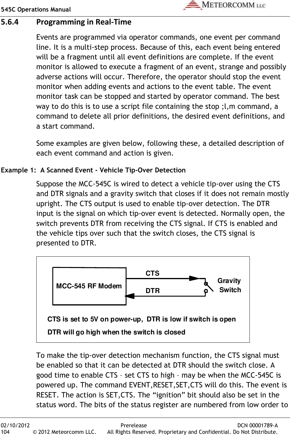
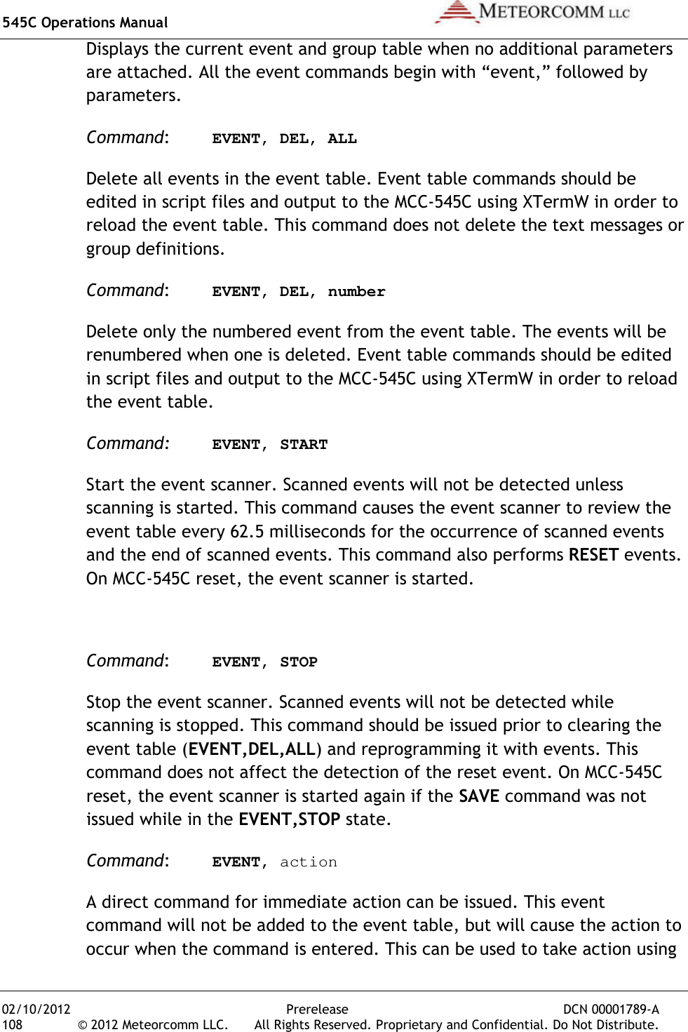
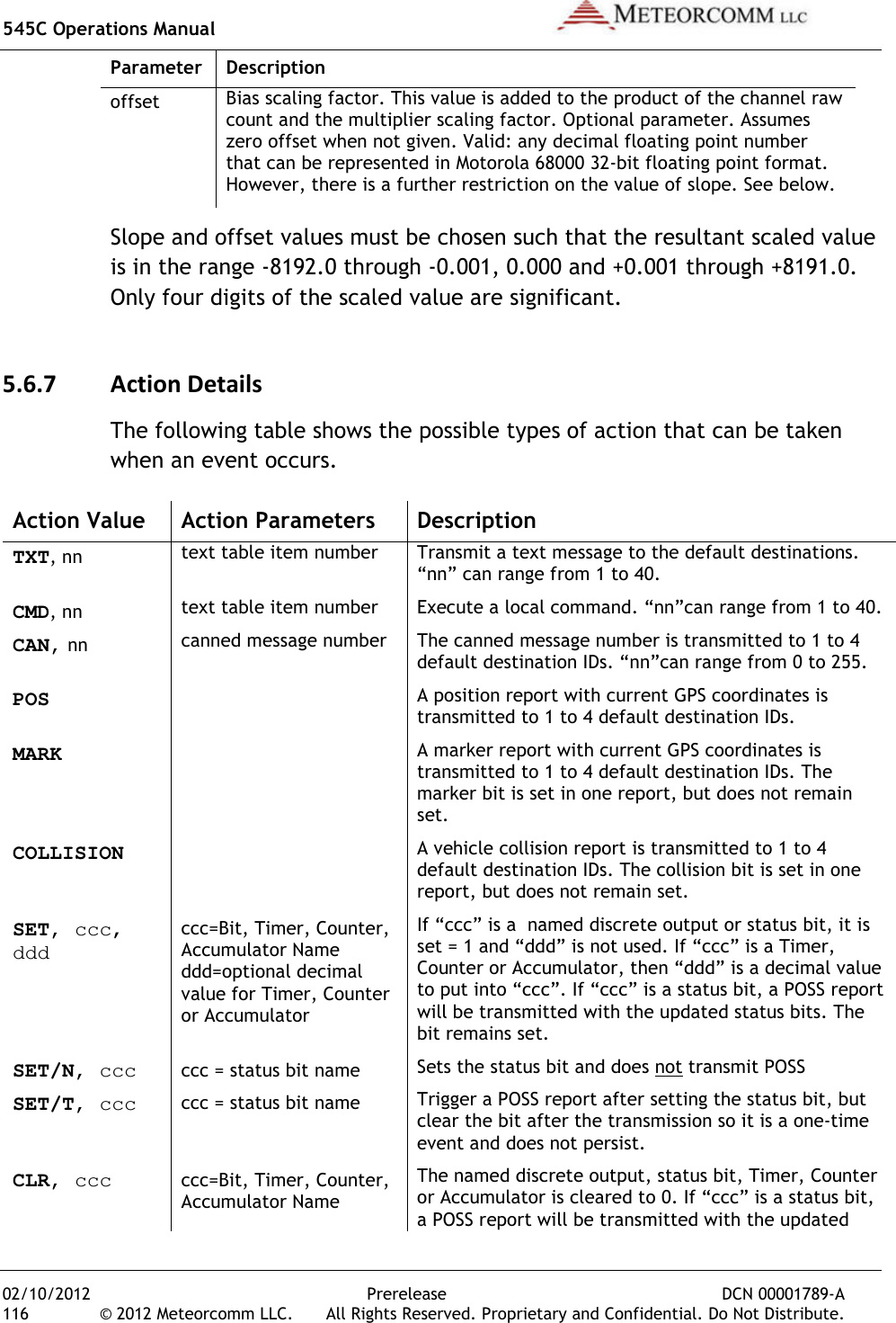
![545C Operations Manual 02/10/2012 38 © 2012 Meteorcomm LLC. Note: The MCC-545C will not transmit if the synthesizer is not locked.Select Site Name A descriptive name may be given to the sbeing installed. The selected site name must be coordinated with your System AdministratorSITE NAME, nnnnnn [ENTER]where: nnnnnn = maximum of 32 alpha Caution: Please doublespacing. Data from a site with an incorrect site name will be mishandled or misrouted by the Host. An incorrect site name can result in significant effort to recover misrouted data.Enter Script Files The appropriate Script File is usually programmed into the MCCthe factory prior to shipmentnot been entered, a new file can be loaded from your operator terminal using XTermW softwarethe MCC-545C to operate as either a Base, Repeater, or Remote StationOther Script Files define any application programs that are performed by the station. For example, the application for a Remote Station may be as a mobile unit reporting position data or as a fixed site reporting sensor data. The procedure for loading the Script File is described below:1. Install the MCCScript File on it into your operator terminal, and load tFile into your 2. Start XTermWand COM port (typically COM1, 9600 baud)are defaults.3. Type factory,default,initinto the MCCPrerelease DCN . All Rights Reserved. Proprietary and Confidential. Do545C will not transmit if the synthesizer is not locked.A descriptive name may be given to the site where the MCC-545C is The selected site name must be coordinated with your System Administrator. To enter a site name use the following command:SITE NAME, nnnnnn [ENTER] where: nnnnnn = maximum of 32 alpha-characters double-check the site name entry for correct spelling and spacing. Data from a site with an incorrect site name will be mishandled or misrouted by the Host. An incorrect site name can result in significant effort to recover misrouted data. The appropriate Script File is usually programmed into the MCCthe factory prior to shipment. If the appropriate Script File has already not been entered, a new file can be loaded from your operator terminal software. There is one Script File that uniquely programs 545C to operate as either a Base, Repeater, or Remote StationOther Script Files define any application programs that are performed by the station. For example, the application for a Remote Station may mobile unit reporting position data or as a fixed site reporting The procedure for loading the Script File is described below: Install the MCC-545C Meteorcomm CD (or diskette), with the Script File on it into your operator terminal, and load tFile into your XTermW subdirectory. XTermW and open a connection at the correct baud rate and COM port (typically COM1, 9600 baud). All other parameters are defaults. factory,default,init to load the default parameters into the MCC-545C. DCN 00001789-A Do Not Distribute. 545C will not transmit if the synthesizer is not locked. 545C is The selected site name must be coordinated with your To enter a site name use the following command: check the site name entry for correct spelling and spacing. Data from a site with an incorrect site name will be mishandled or misrouted by the Host. An incorrect site name can result in significant effort The appropriate Script File is usually programmed into the MCC-545C at If the appropriate Script File has already not been entered, a new file can be loaded from your operator terminal e Script File that uniquely programs 545C to operate as either a Base, Repeater, or Remote Station. Other Script Files define any application programs that are performed by the station. For example, the application for a Remote Station may mobile unit reporting position data or as a fixed site reporting CD (or diskette), with the Script File on it into your operator terminal, and load the Script and open a connection at the correct baud rate All other parameters to load the default parameters](https://usermanual.wiki/Meteorcomm/54505003-01.Users-Manual/User-Guide-1643156-Page-48.png)
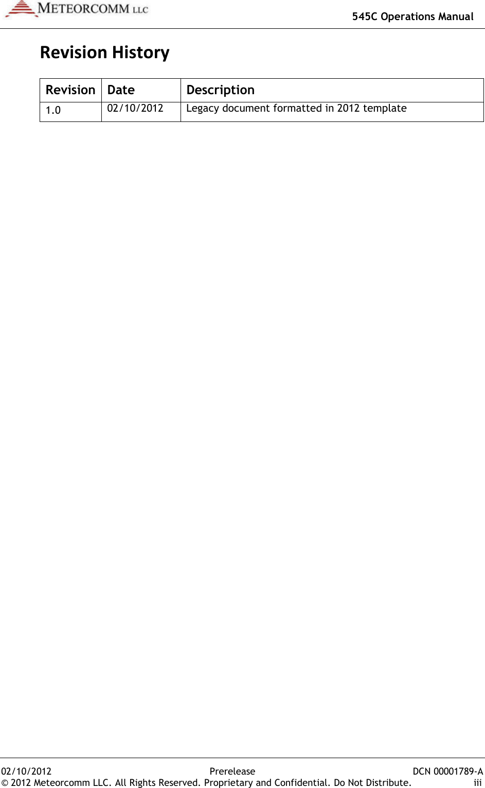
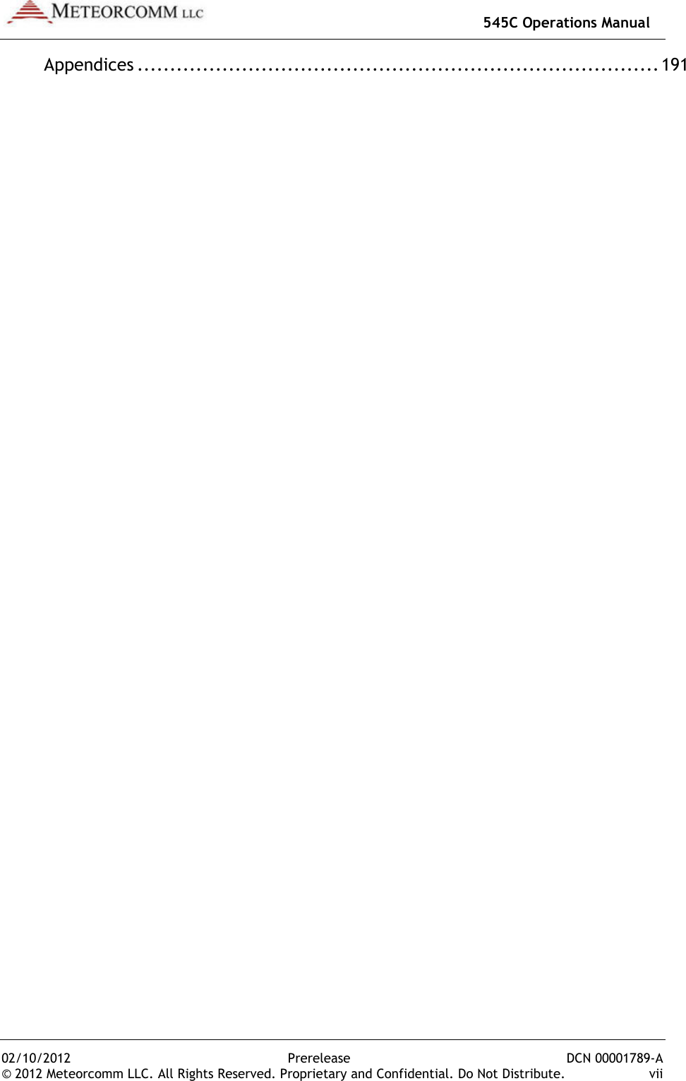
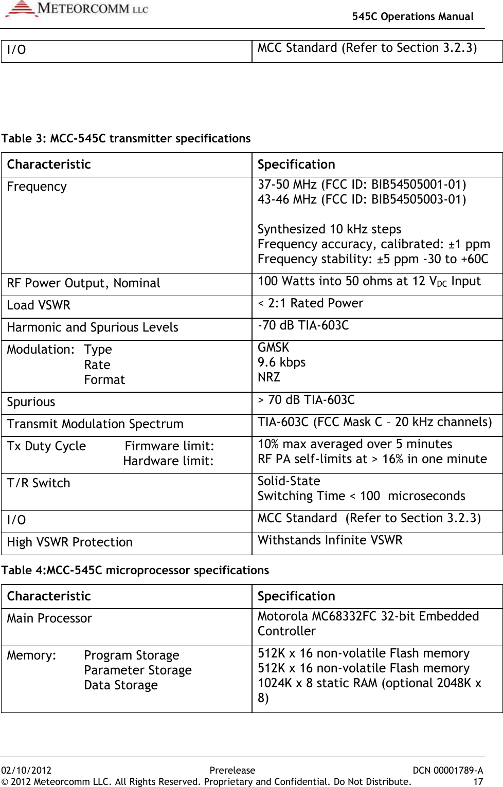
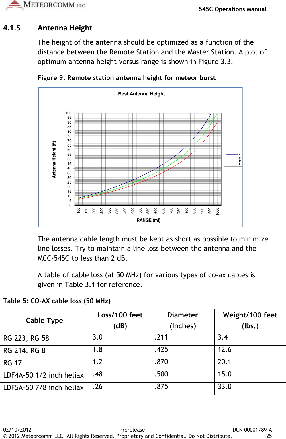
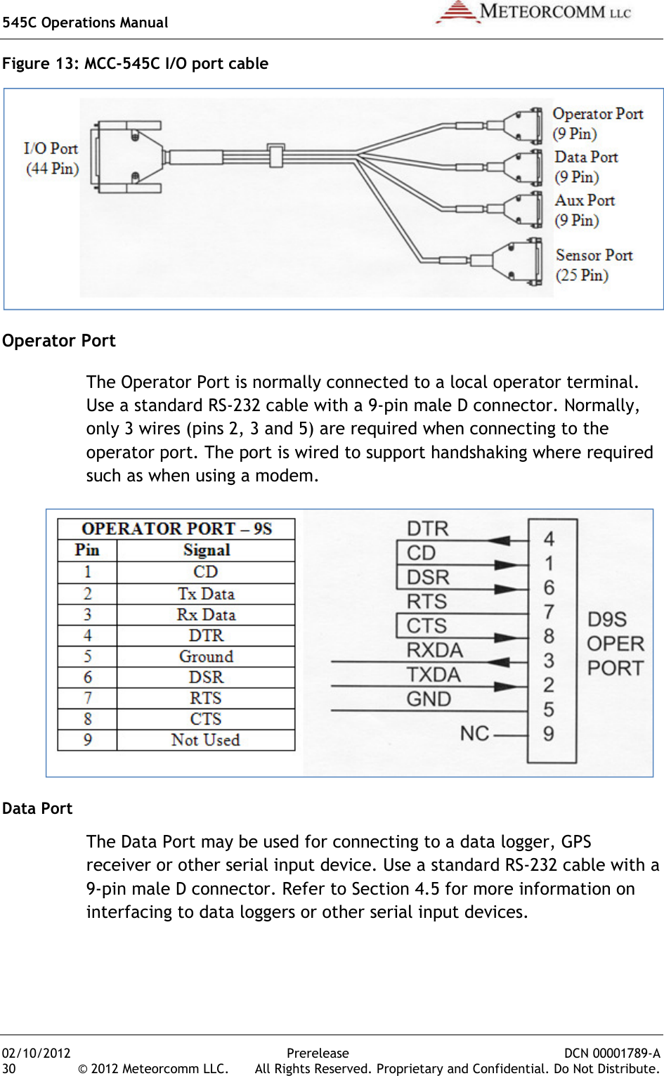
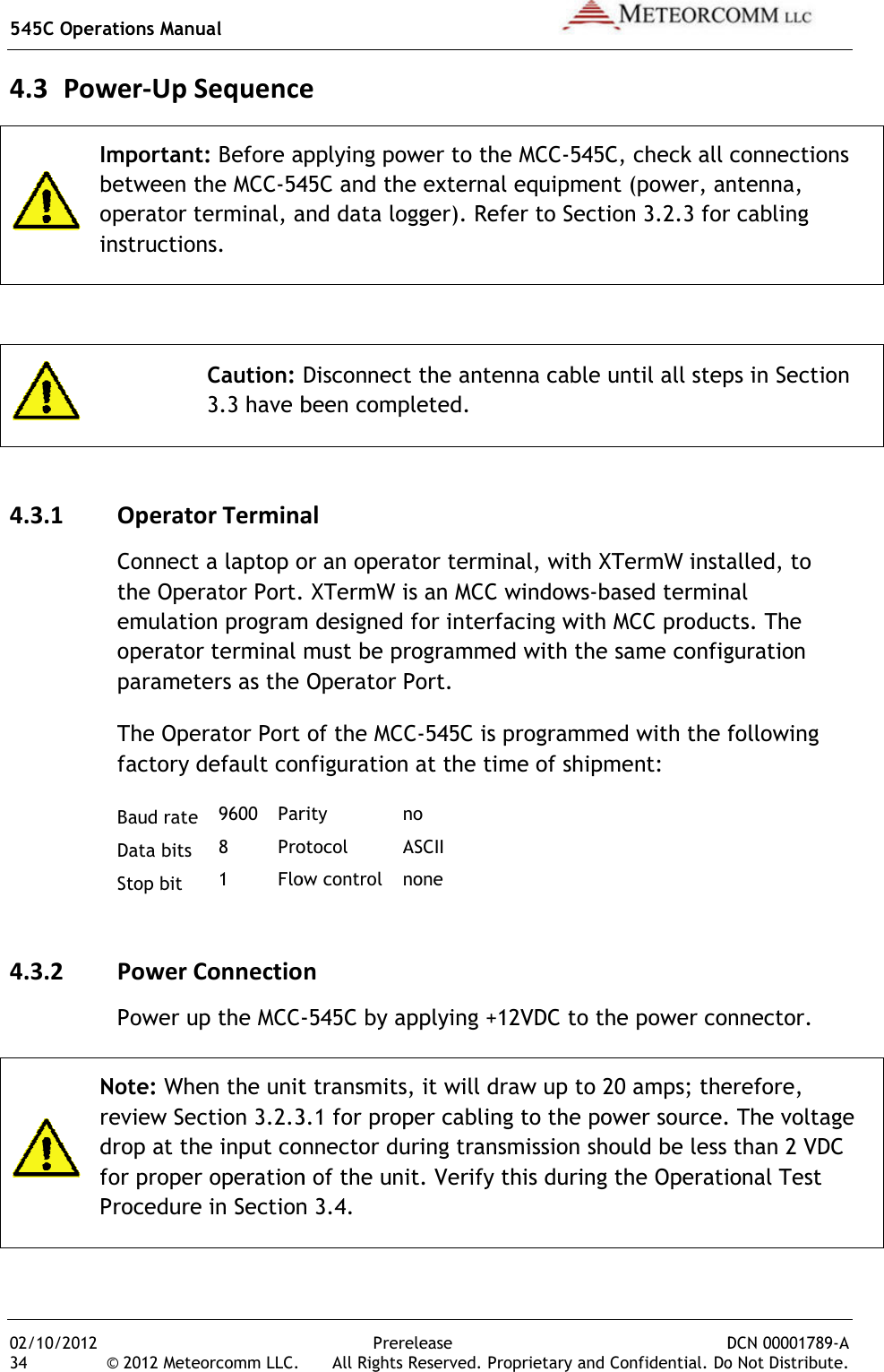
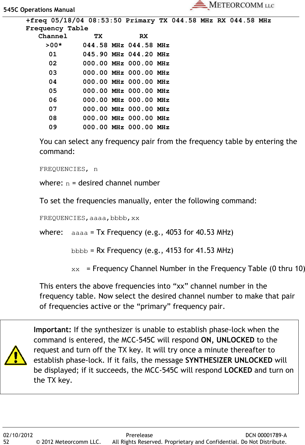
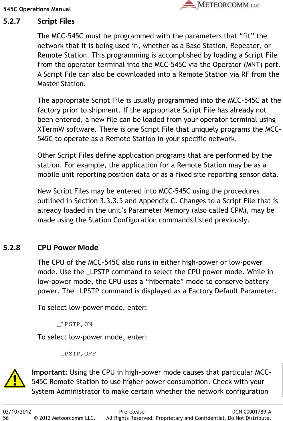
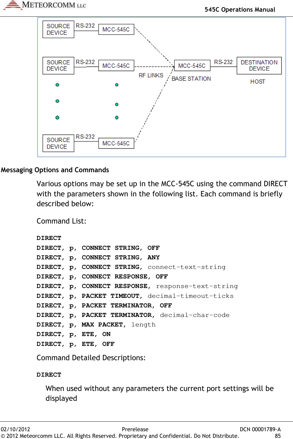
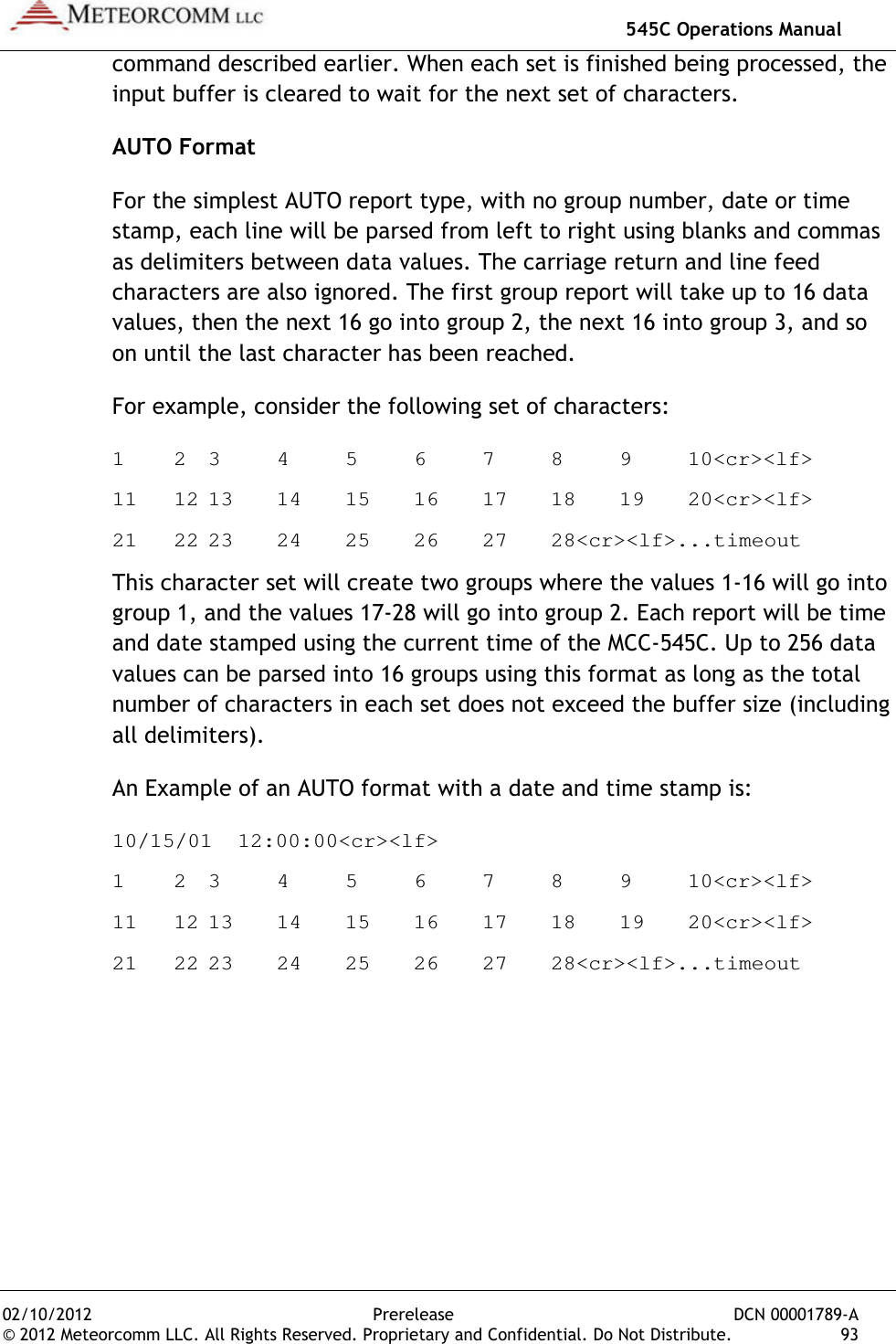
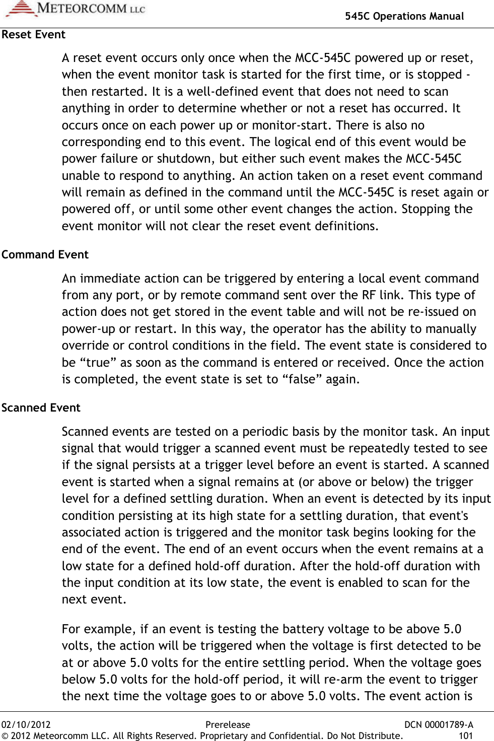
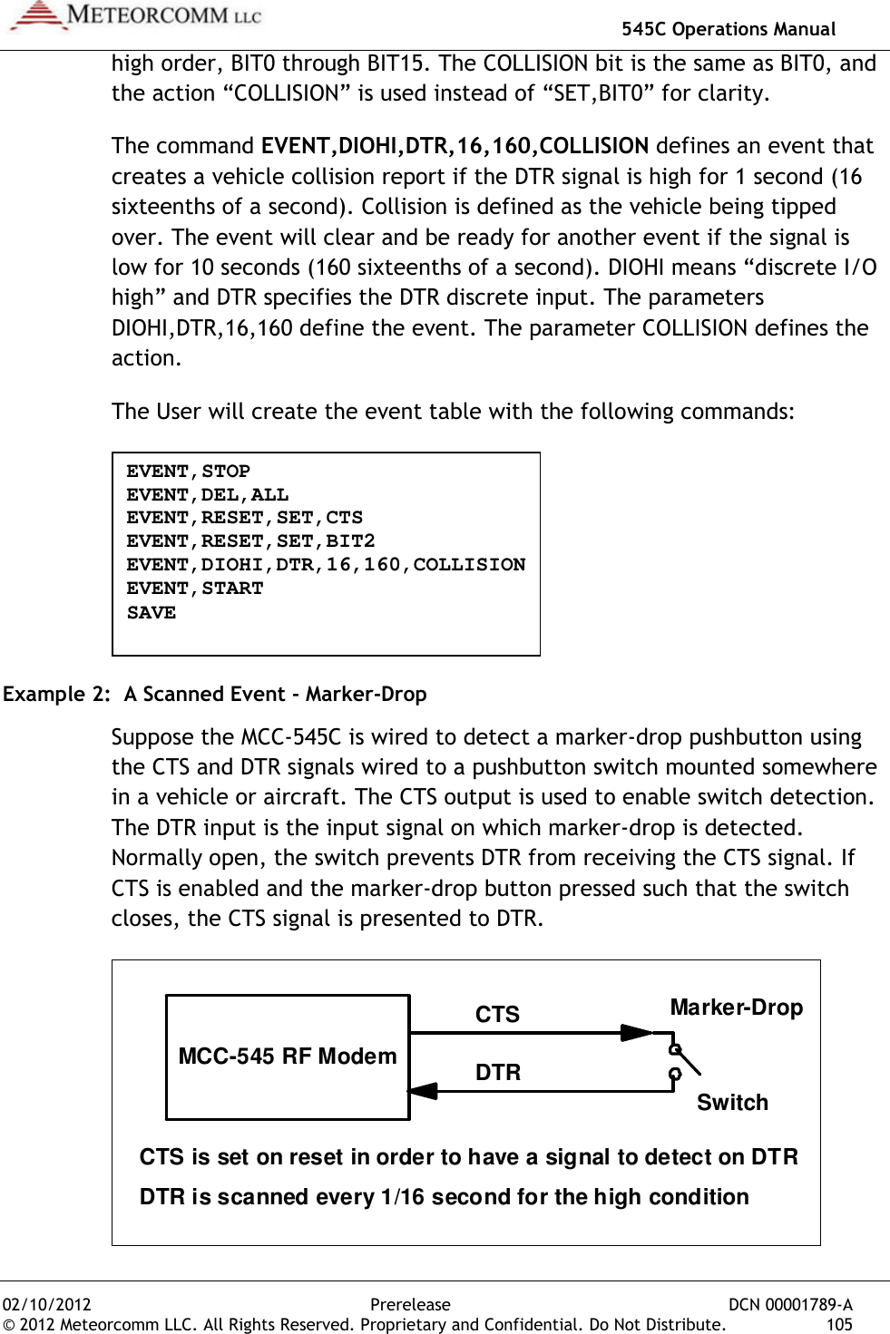
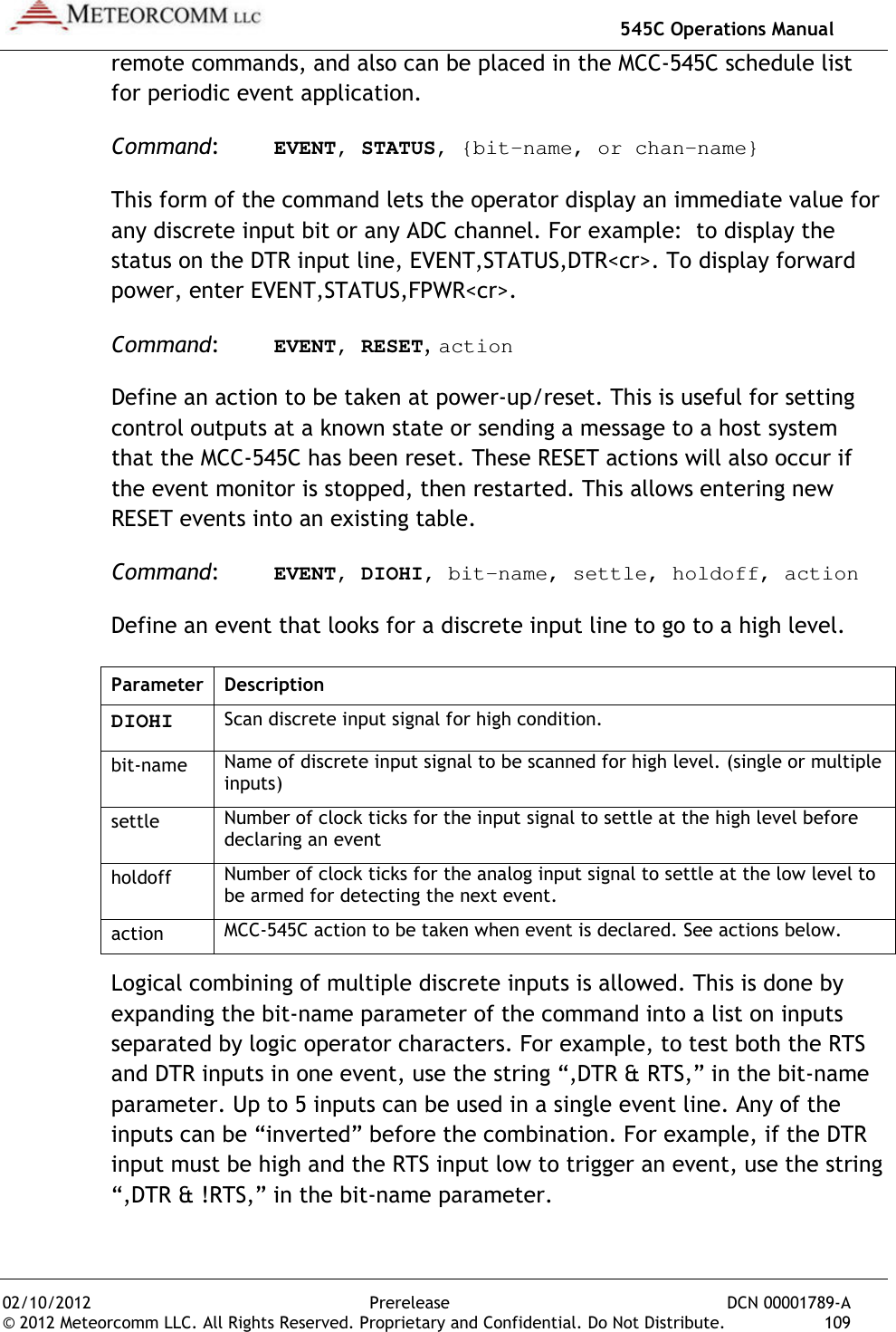
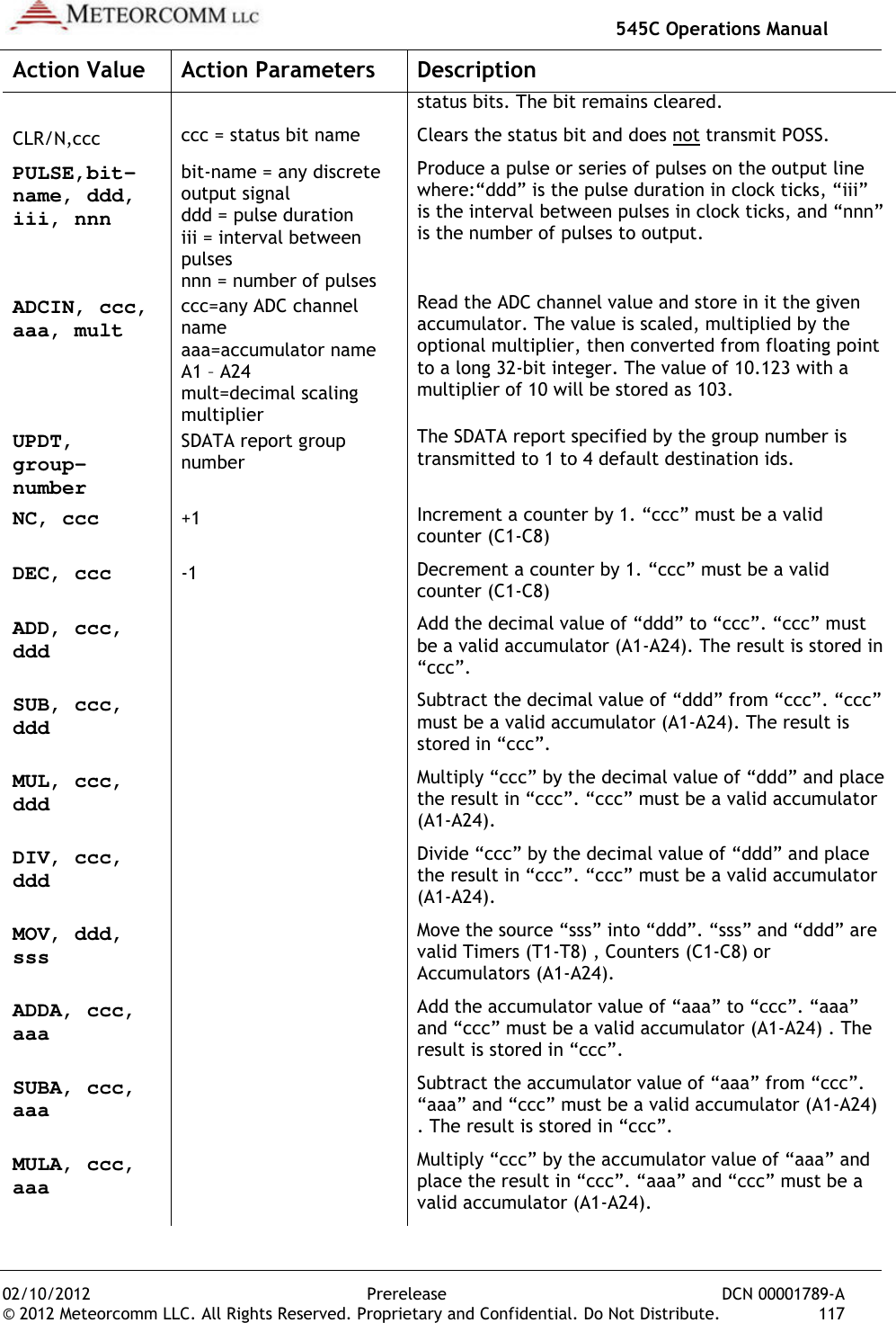
![02/10/2012 © 2012 Meteorcomm LLC. All Right4. From the Script. 5. Select the appropriate Script File in the Double-click the file name to start execution.The commands in the Script File are executed one at a time until the end of the file is reachedreview the command responsesCOMMAND, BAD PARAMETER, or a similar message, the Script File may have an error in itMCC or your System Administrator for a replacement.You may verify that the correct configuration file has been loaded by entering the three commands: THIS COMPLETES THE INTIALIZATION PROCEDURE4.4 Operational Test Procedure Note: Be sure to connect the antenna if it was disconnected per the CAUTION note of Section 3.3.4.4.1 RF Test A very thorough RF test can be made by entering the command TEST [ENTER]. TEST causes the processor to turn the transmitter ON and measures the forward and reverse RF power that is being transmittedalso measures the battery voltage under load and the antenna noise voltage. 545C Operations ManualPrerelease hts Reserved. Proprietary and Confidential. Do Not DistribuFrom the Scripts pull-down menu in XTermW, choose Execute Select the appropriate Script File in the XTermW subdirectoryclick the file name to start execution. The commands in the Script File are executed one at a time until the the file is reached. Press the “up arrow” key to scroll up and review the command responses. If any commands result in BAD COMMAND, BAD PARAMETER, or a similar message, the Script File may have an error in it. If so, the script file needs to be correctedMCC or your System Administrator for a replacement. You may verify that the correct configuration file has been loaded by entering the three commands: ASSIGN, SNP, and CONFIG. THIS COMPLETES THE INTIALIZATION PROCEDUREOperational Test Procedure Be sure to connect the antenna if it was disconnected per the CAUTION note of Section 3.3. A very thorough RF test can be made by entering the command TEST TEST causes the processor to turn the transmitter ON and forward and reverse RF power that is being transmittedalso measures the battery voltage under load and the antenna noise 545C Operations Manual DCN 00001789-A ibute. 39 , choose Execute subdirectory. The commands in the Script File are executed one at a time until the Press the “up arrow” key to scroll up and If any commands result in BAD COMMAND, BAD PARAMETER, or a similar message, the Script File may If so, the script file needs to be corrected. Contact You may verify that the correct configuration file has been loaded by . THIS COMPLETES THE INTIALIZATION PROCEDURE Be sure to connect the antenna if it was disconnected per the A very thorough RF test can be made by entering the command TEST TEST causes the processor to turn the transmitter ON and forward and reverse RF power that is being transmitted. It also measures the battery voltage under load and the antenna noise](https://usermanual.wiki/Meteorcomm/54505003-01.Users-Manual/User-Guide-1643156-Page-49.png)
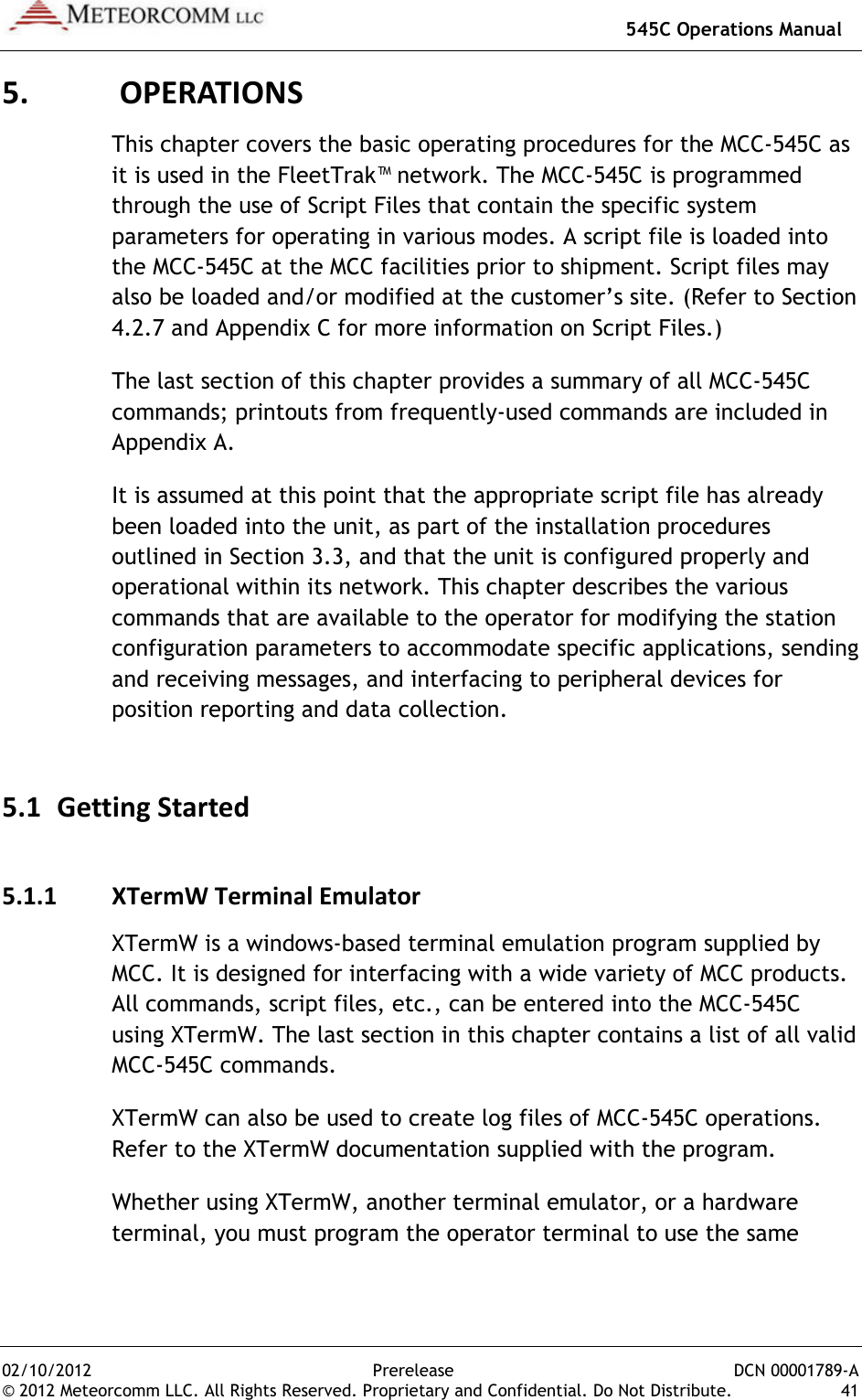
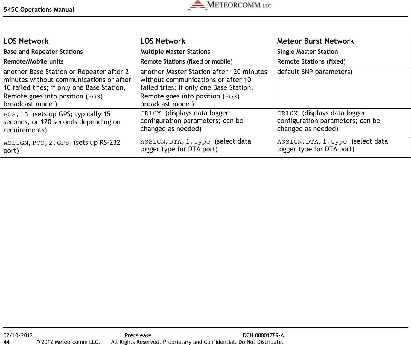
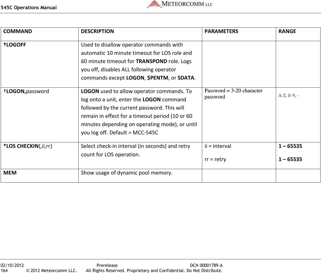
![545C Operations Manual 02/10/2012 Prerelease DCN 00001789-A 42 © 2012 Meteorcomm LLC. All Rights Reserved. Proprietary and Confidential. Do Not Distribute. configuration parameters as the MCC-545C Operator Port. The Operator Port of the MCC-545C has the following factory default configuration: Baud rate 9600 Data bits 8 Stop bit 1 Parity no Protocol ASCII Flow control none 5.1.2 HELP Command Entering HELP [ENTER] displays all of the commands used in the operation and maintenance of the MCC-545C. To obtain descriptive information about a particular command and how it is used by the MCC-545C, enter the command type. For example: HELP, ASSIGN [ENTER]. Refer to the last section of this chapter for a complete list of MCC-545C commands. 5.1.3 Role-Based Operations The role that the MCC-545C plays in a communications network determines how it should be configured. There are three basic roles that an MCC-545C can be used in, depending on the network type: • LOS Network consisting of Base and Repeater Stations, and Remote/Mobile units; Base Stations do not communicate with each other in this type of network. This is a typical FleetTrak™ network. • LOS Network consisting of one or more Master Stations and Remote Stations (either fixed position or mobile units); Master Stations can communicate with each other in this type of network. This is a typical DataNet network. • Meteor Burst network consisting of a single Master Station communicating with Remote Stations in fixed positions; Remote Stations do not communicate with each other in this type of network. This is a typical Meteor Burst network.](https://usermanual.wiki/Meteorcomm/54505003-01.Users-Manual/User-Guide-1643156-Page-52.png)
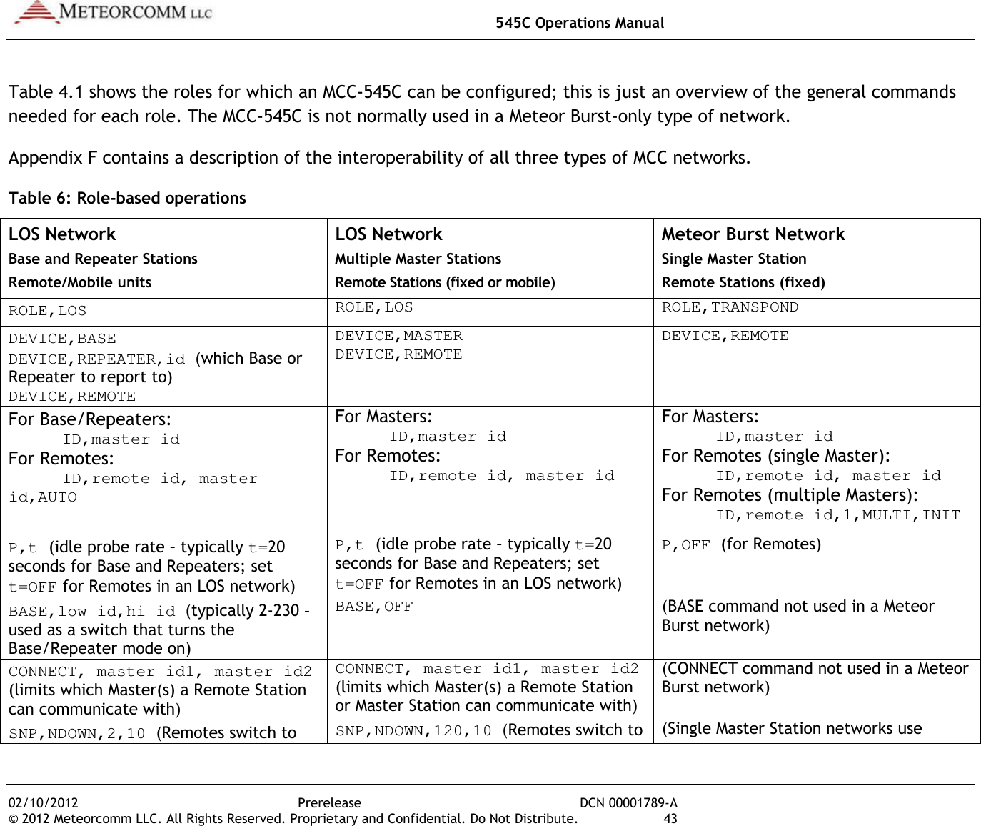
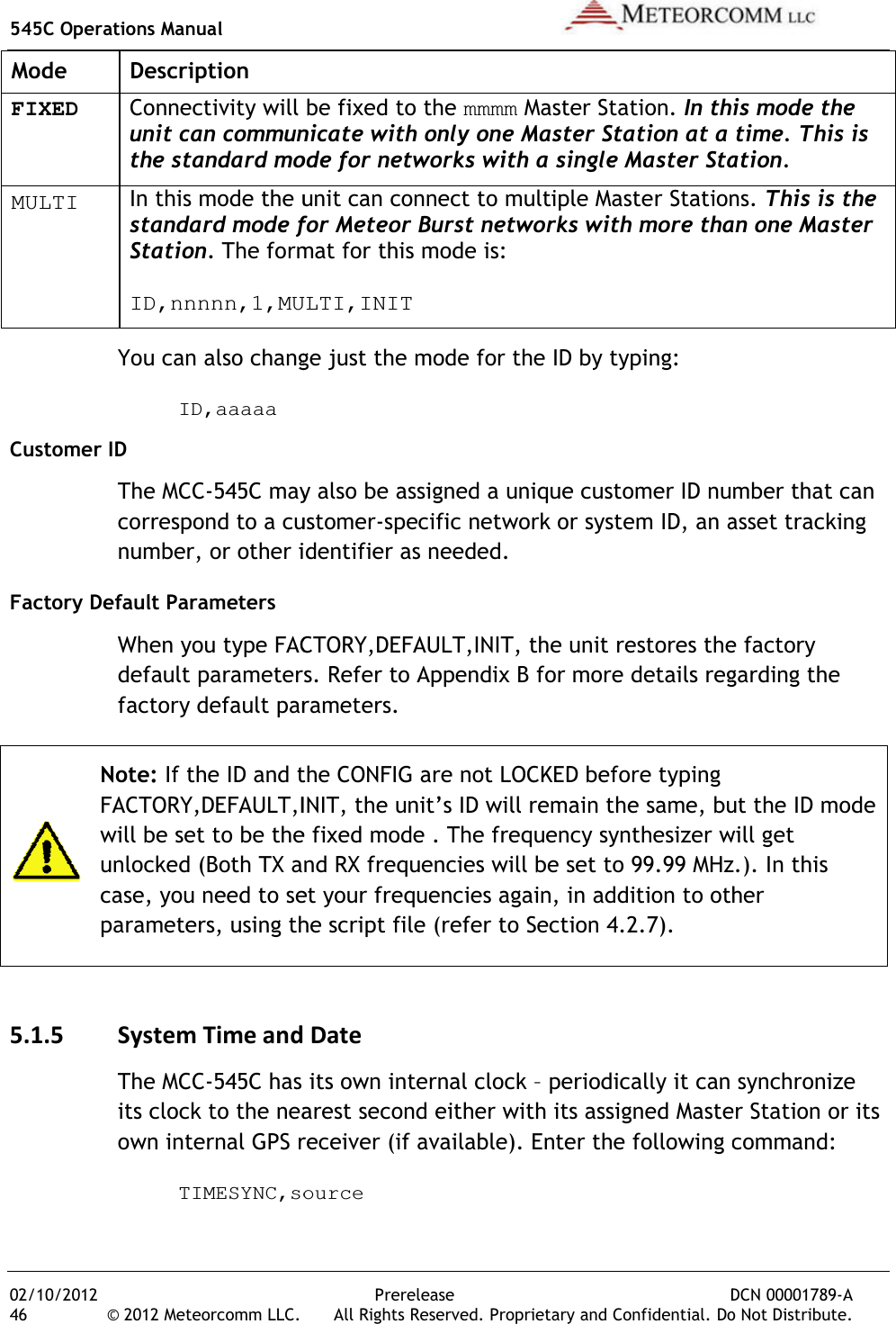
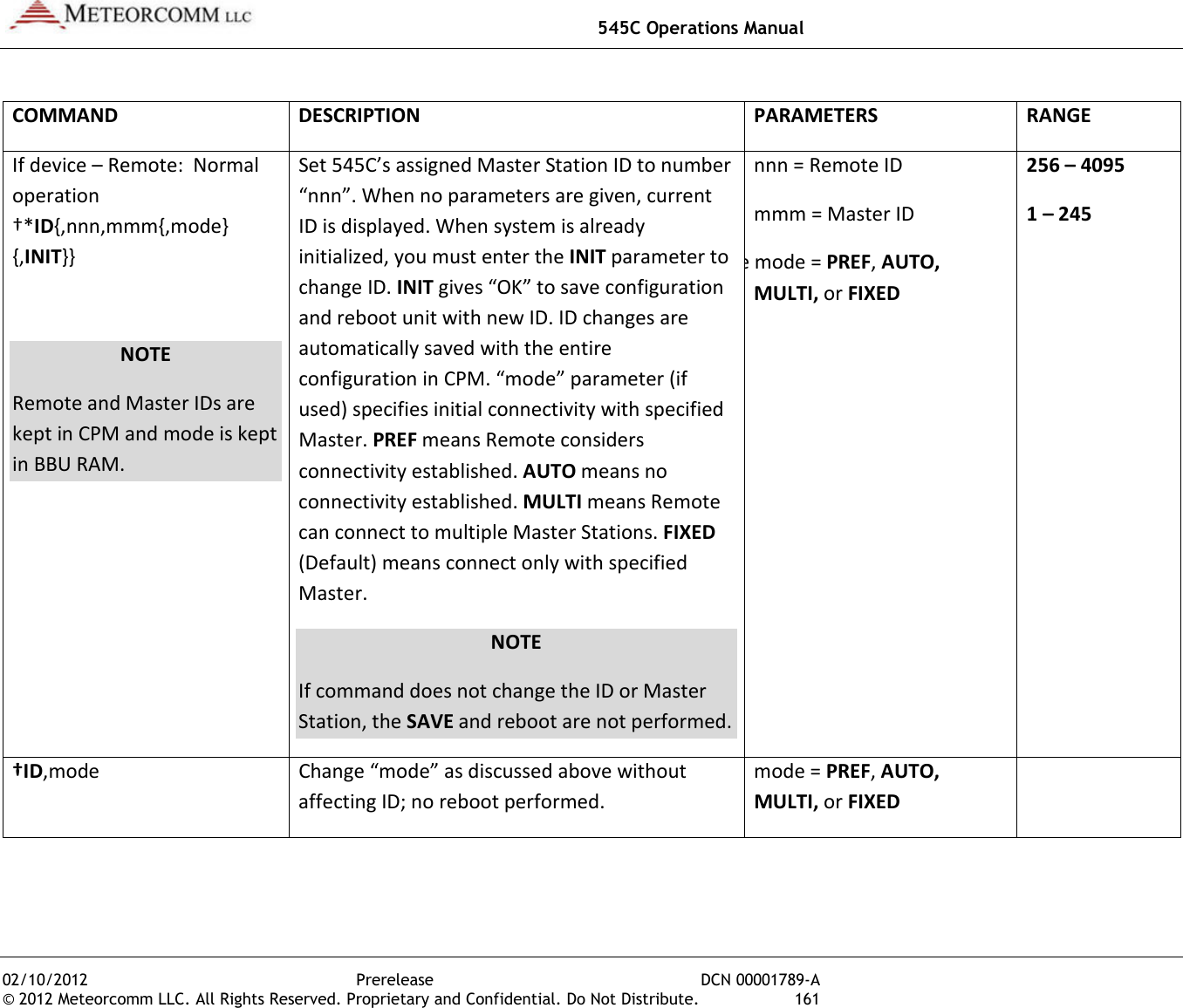
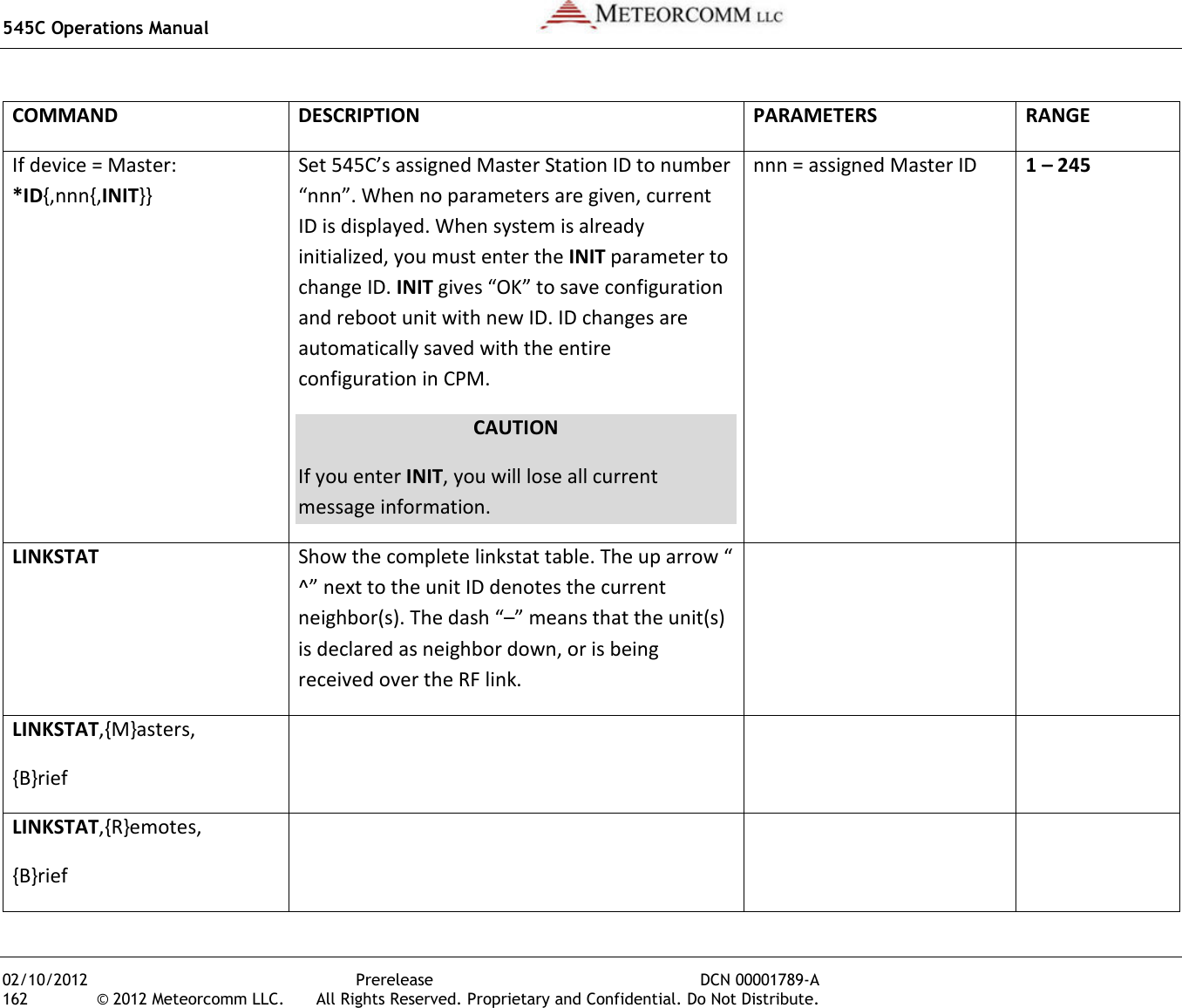
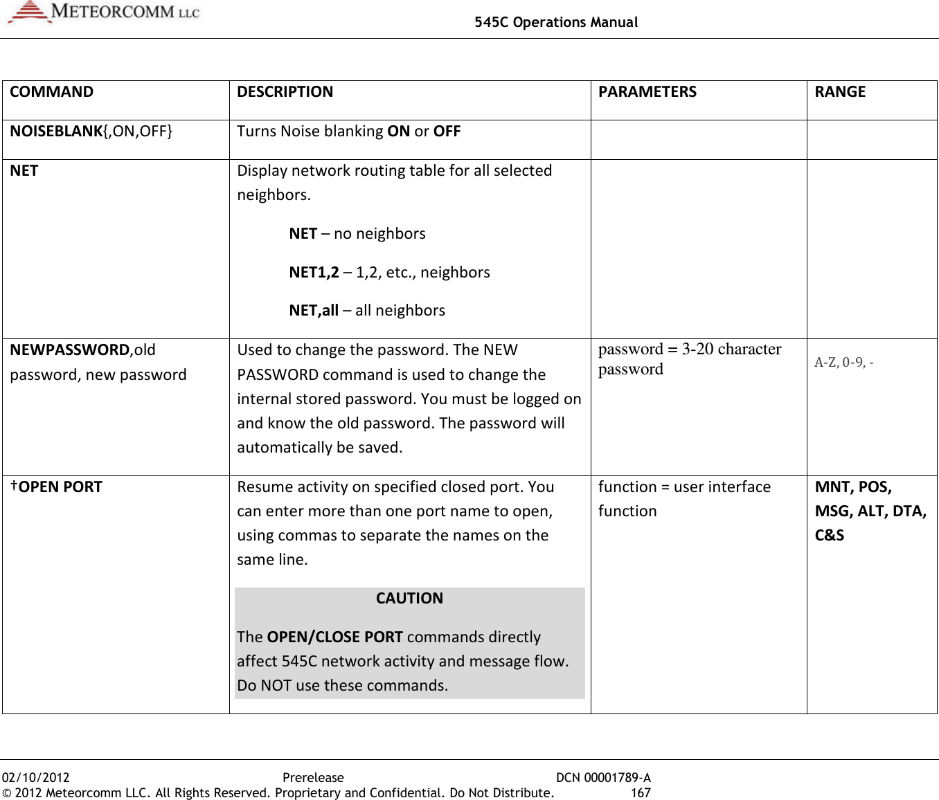
![545C Operations Manual 02/10/2012 Prerelease DCN 00001789-A © 2012 Meteorcomm LLC. All Rights Reserved. Proprietary and Confidential. Do Not Distribute. 45 5.1.4 Unit Identification and Factory Settings Unit ID Every MCC unit is programmed at the factory with a 16-bit unit ID. This allows up to 65,536 unique ID numbers per network. Type the command ID and press [ENTER] to display the unit ID number on the operator terminal. In some cases this number will be “locked” and cannot be changed in the field; you can type LOCK to determine if the ID is locked or not. Under some circumstances the ID may have to be changed on-site. It can only be done if the ID is not locked. In that event, this action must be coordinated with both MCC and your System Administrator. Failure to do so may result in data or messages being misrouted or lost. In addition, the network topography and statistics will receive incorrect data that will impair network performance. To change the ID, enter the following command: ID,nnnnn,mmmm{,aaaaa},INIT where:nnnnnn = unit ID mmmm = Master Station assignment aaaaa = Master select mode: PREF, AUTO, MULTI, or FIXED Obtain the proper Master Station assignment and select mode from your System Administrator. The MCC-545C will save this ID and will use it whenever the unit is powered up or reset. Mode Description PREF Unit connects to the mmmm Master Station for the NDOWN period (set with SNP command). After NDOWN period unit connects to the Master Station that it has received the most syncs from. In this mode the unit can communicate with only one Master at a time. AUTO Unit connects to the mmmm Master Station, if it is not successful it switches to another Master Station. It will stay with that Master Station as long as it can communicate with it. In this mode the unit can communicate with only one Master at a time. This is the standard mode for FleetTrak™ networks.](https://usermanual.wiki/Meteorcomm/54505003-01.Users-Manual/User-Guide-1643156-Page-55.png)
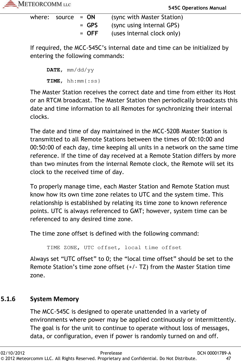
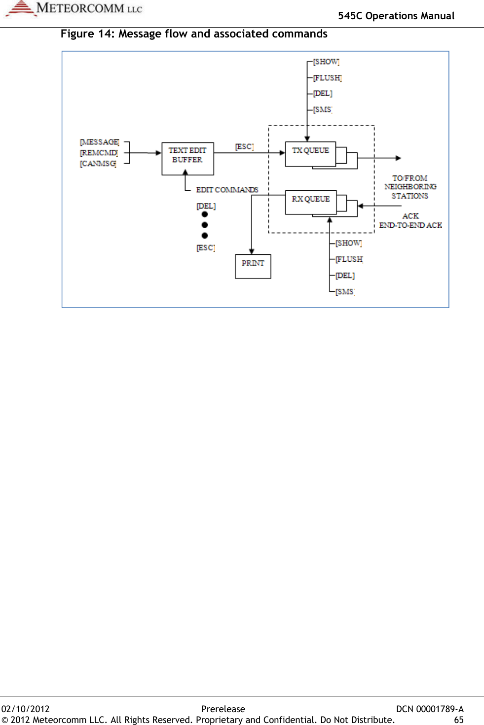
![545C Operations Manual 02/10/2012 Prerelease DCN 00001789-A 66 © 2012 Meteorcomm LLC. All Rights Reserved. Proprietary and Confidential. Do Not Distribute. The following operations are explained in this section: Section Operations 4.3.1 Entering and Deleting Messages 4.3.2 Editing Messages 4.3.3 Sending Messages 4.3.4 Sending Commands 4.3.5 Sending Canned Messages 4.3.6 Receiving Messages 4.3.7 Examining Message Status 4.3.8 Examining and Revising Message Queues 5.3.1 Entering and Deleting Messages All messages are composed and edited in the Text Edit Buffer. Messages may be up to 3,570 characters in length. When composing the message you must press [ENTER] at the end of each 80 character line. There is a default destination programmed into the MCC-545C during the installation and initialization of the unit when it is first brought on-line in the network. If a message is not given a specific destination it will be sent to the default destination only. To enter a message: 1. Type MESSAGE. The operator terminal responds with ENTER TEXT. The MCC-545C will now be in Compose-and-Edit mode (as opposed to normal Command-Line Entry mode). 2. Enter a message up to 3,570 characters in length, pressing [ENTER] at the end of each 80 character line. 3. Press the [ESC] key. The message is transferred to a Transmit queue and will be automatically transmitted to the default destination at a priority level R.](https://usermanual.wiki/Meteorcomm/54505003-01.Users-Manual/User-Guide-1643156-Page-76.png)
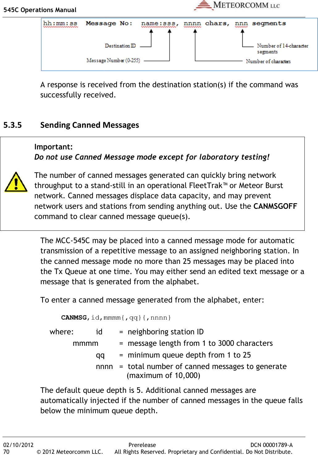
![02/10/2012 © 2012 Meteorcomm LLC. All Rights Reserved.The following message is displayed on the operator terminal:hh:mm:ss Message No: hh:mm:ss ROUTING name :If you wish to send a message to multiple destinations, and at a different priority level, type: MESSAGE,p,dest1,dest2,...dest n where: p dest n Note: If you also want to send the must enter its station numerical ID as one of the destination parameters (“dest1”, “dest2”, etc.) as specified above.There are three other special editing functions that may be used:1. To Retransmit the Previously ETo retransmit a previously entered message, simply press the [ESC] key after the operator terminal prints pressed. The previous message entered into the Text Edit Buffer is then sent to the destinationcommand. 2. To Revise the Previously Entered Message To revise a previously entered message, press [CTRL]TEXT prompt to revise a previously entered message or to recover from an aborted session. The at the end of the message3. To Delete a MessageTo delete a message after it has been placed in the Tx Queue, type:DELMSG,ID:sss where: IDsss545C Operations ManualPrerelease DCN © 2012 Meteorcomm LLC. All Rights Reserved. Proprietary and Confidential. Do Not Distribute. The following message is displayed on the operator terminal:Message No: name:ss,nnnn chars, nnn segments ROUTING name :sss TXT sss/nn TO: name If you wish to send a message to multiple destinations, and at a different priority level, type: ,p,dest1,dest2,...dest n = any priority level from A (highest) to Z (lowest). = numerical ID of the stations to which the message is routed. If you also want to send the message to your default destination, you must enter its station numerical ID as one of the destination parameters (“dest1”, “dest2”, etc.) as specified above. There are three other special editing functions that may be used:To Retransmit the Previously Entered Message To retransmit a previously entered message, simply press the [ESC] key after the operator terminal prints ENTER TEXT and before any other key is The previous message entered into the Text Edit Buffer is then sent to the destinations that are now designated in the MESSAGETo Revise the Previously Entered Message To revise a previously entered message, press [CTRL]T after the prompt to revise a previously entered message or to recover from an The previous message is displayed, with the cursor placed at the end of the message. You may now resume editing the message.To Delete a Message To delete a message after it has been placed in the Tx Queue, type:ID = numerical station ID sss = message serial number 545C Operations Manual DCN 00001789-A 67 The following message is displayed on the operator terminal: If you wish to send a message to multiple destinations, and at a different = any priority level from A (highest) to Z (lowest). ID of the stations to which the message to your default destination, you must enter its station numerical ID as one of the destination parameters There are three other special editing functions that may be used: To retransmit a previously entered message, simply press the [ESC] key and before any other key is The previous message entered into the Text Edit Buffer is then MESSAGE after the ENTER prompt to revise a previously entered message or to recover from an previous message is displayed, with the cursor placed You may now resume editing the message. To delete a message after it has been placed in the Tx Queue, type:](https://usermanual.wiki/Meteorcomm/54505003-01.Users-Manual/User-Guide-1643156-Page-77.png)
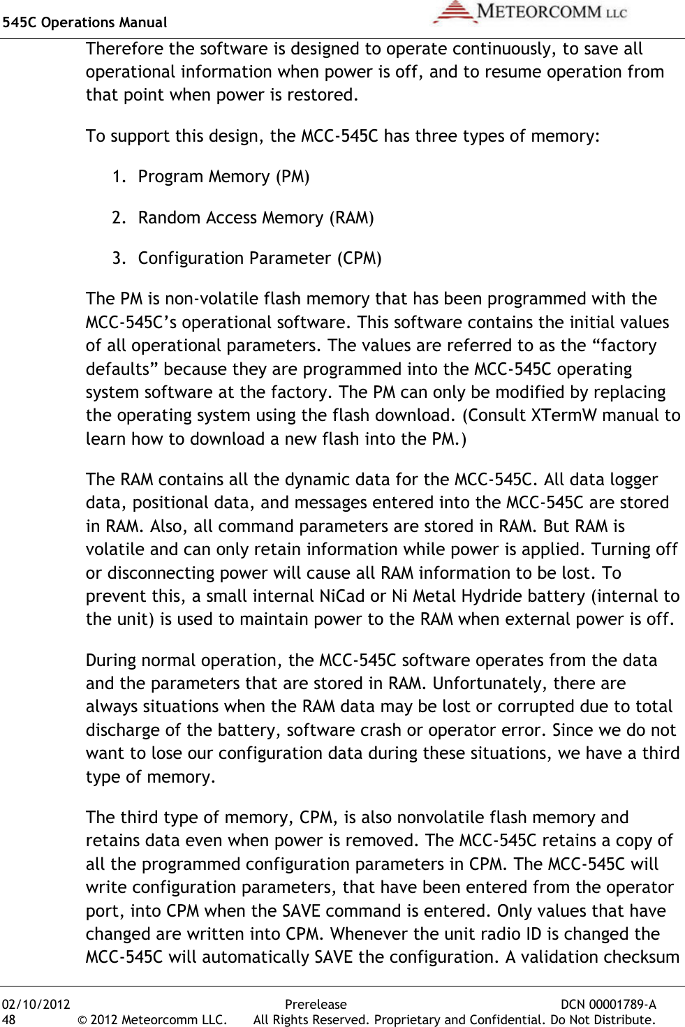
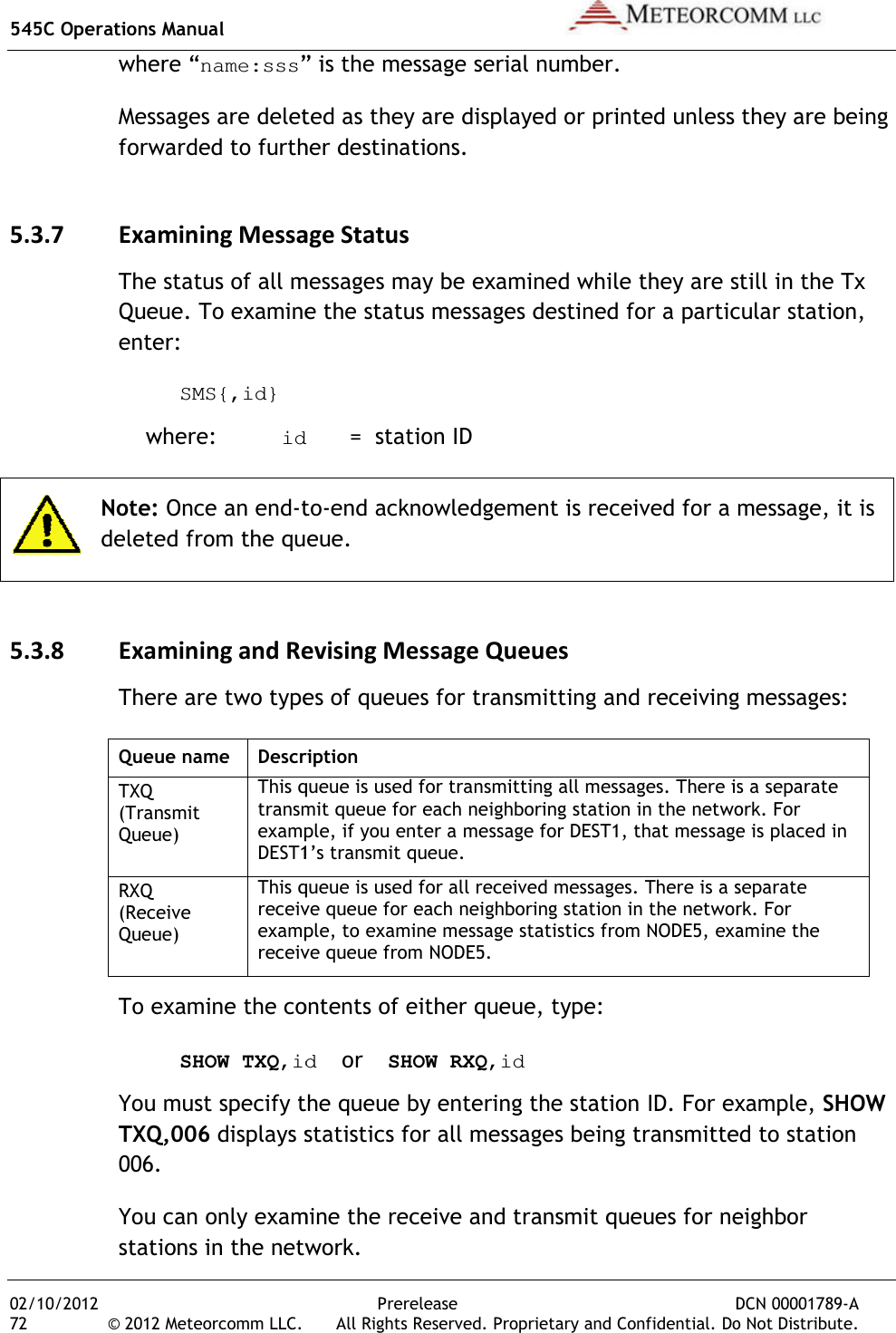
![545C Operations Manual 02/10/2012 Prerelease DCN 00001789-A 68 © 2012 Meteorcomm LLC. All Rights Reserved. Proprietary and Confidential. Do Not Distribute. The operator terminal displays the date and time, followed by MESSAGE DELETED. 5.3.2 Editing Messages The following editing functions may be used from the keyboard while the message is in the Text Edit Buffer. Key Function [DEL] Deletes the last character entered. [CTRL]R Prints the current line of text on the next line down. [CTRL]I Performs a fixed tab function \ Removes the current line from the edit buffer. [ENTER] Performs a carriage return and line feed. [LF] Performs a carriage return and line feed. [CTRL]X Removes the current line from the edit buffer and places the cursor at the end of the previous line. [CTRL]T Prints the contents of the edit buffer & puts cursor at the end of text. [CTRL]D Erases the entire contents of the edit buffer. [CTRK]A Aborts the edit mode and returns to the command mode. A “+” indicates the command mode. [ESC] Leaves text edit mode and queues the message for transmission. 5.3.3 Sending Messages Messages are automatically stored for transmission with the [ESC] key. Each message is placed in the Tx Queue according to its assigned priority. Messages of equal priority are placed in the Tx Queue in the order received from the Text Edit Buffer. The following display appears on the operator terminal as the MCC-545C stores and routes a message: hh:mm:ss Message No: name:ss,nnnn chars, nnn segments](https://usermanual.wiki/Meteorcomm/54505003-01.Users-Manual/User-Guide-1643156-Page-78.png)
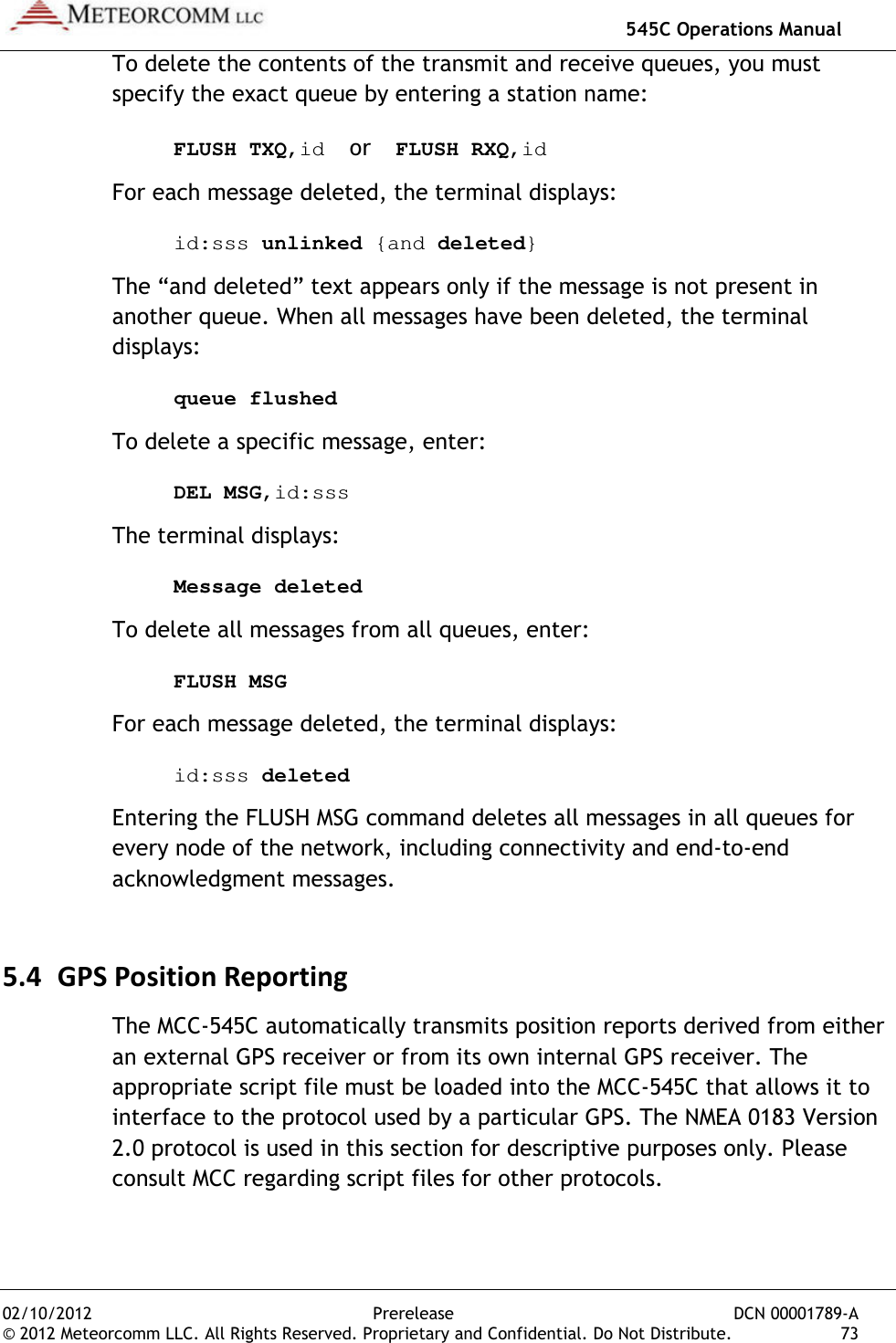
![545C Operations Manual 02/10/2012 Prerelease DCN 00001789-A © 2012 Meteorcomm LLC. All Rights Reserved. Proprietary and Confidential. Do Not Distribute. 69 hh:mm:ss ROUTING name :sss TXT sss/nn TO: name Messages are transmitted in packets and are routed to their destination in a Store-and-Forward manner, using the most efficient routing within the packet switched network. The originating station receives an acknowledgement (ACK) if the message has been received successfully by the first routing station. mm/dd/yy hh:mm:ss TXTMSG ACK name:sss, xxxx CHARS FROM name When the entire message has been delivered to its final destination, the operator terminal displays an end-to-end acknowledgement: hh:mm:ss END-TO-END ACK OF name:sss FROM name If the end-to-end ACK is not received within the specified time-to-live limit, the MCC-545C purges the message from the Tx Queue and displays the following message: hh:mm:ss MESSAGE TIME-TO-LIVE EXPIRED, MSG.NO:sss, DESTN: name You must then re-enter the message. Continued failure to successfully transmit a message indicates that something may be wrong with the equipment or the link (e.g., excessive noise interference). 5.3.4 Sending Commands Commands may be sent to any station within the network. The entry of a command is similar to the MESSAGE command described in Section 4.3.1. REMCMD,R,dest1,dest2,...destn where: R = priority level dest = numerical ID of destination station(s) The operator is then prompted to enter the text of the command using the message editor. Once the command is entered, press the [ESC] key to send the command. The operator terminal will display:](https://usermanual.wiki/Meteorcomm/54505003-01.Users-Manual/User-Guide-1643156-Page-79.png)
![545C Operations Manual 02/10/2012 Prerelease DCN 00001789-A © 2012 Meteorcomm LLC. All Rights Reserved. Proprietary and Confidential. Do Not Distribute. 71 If the Total parameter was entered, the canned message mode stops when the desired number of messages has been transmitted. To enter an edited canned message, enter: CANMSG,id where “id” is the neighboring station’s ID. After composing your message press the [ESC] key. The MCC-545C automatically routes up to 25 copies of the canned message to the destination station. Each canned message is acknowledged by the selected neighboring station. No end-to-end acknowledgements are received for canned messages. To manually terminate the mode, enter: CANMSG OFF,id Canned messages are normally not printed at the destination station. To print canned messages as they are received, enter: CANMSG MODE,PRINT To turn off the print mode, enter: CANMSG MODE,NO PRINT 5.3.6 Receiving Messages When a new message is received, it is announced by the following display: hh:mm:ss RECEIVING name:sss TXT sss/nn FROM name ROUTED TO: name The MCC-545C then generates an acknowledgement of the message packet and transmits the ACK to the neighbor from whom the message was received: hh:mm:ss TXTMSG ACK name:sss, nnnn CHARS FROM name When the destination MCC-545C receives a complete message, it displays the following message: hh:mm:ss MSG RECEIVED name:sss, xxxx CHARS text.................. **end-of-message**](https://usermanual.wiki/Meteorcomm/54505003-01.Users-Manual/User-Guide-1643156-Page-81.png)
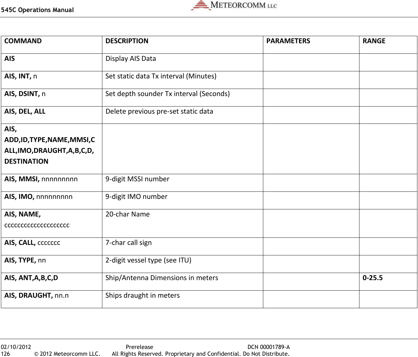
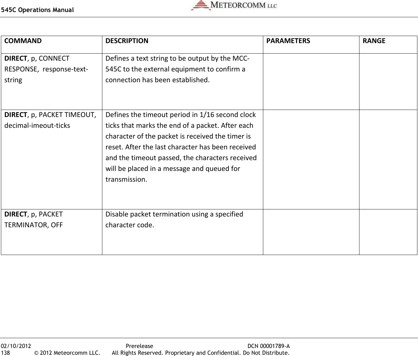

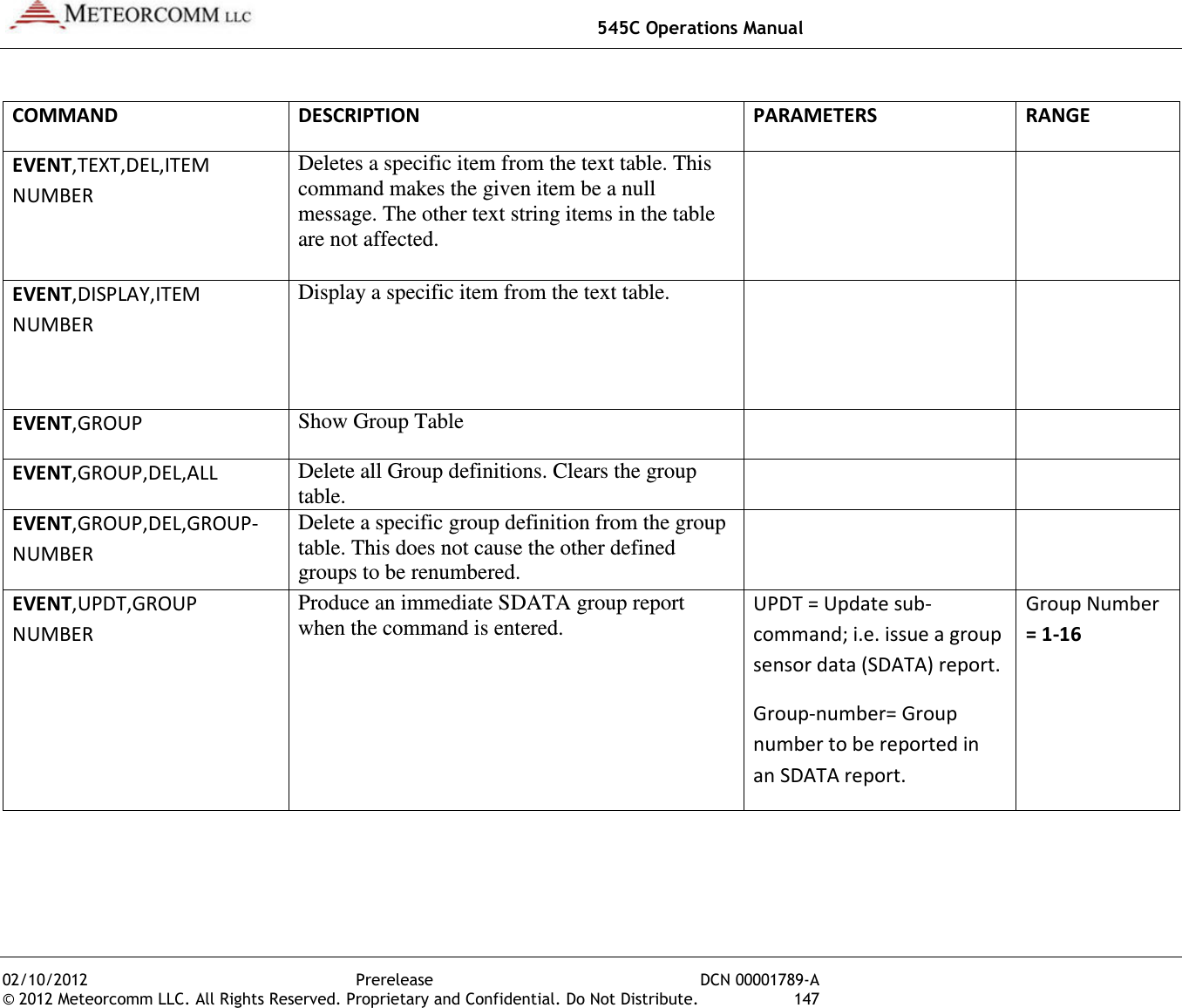
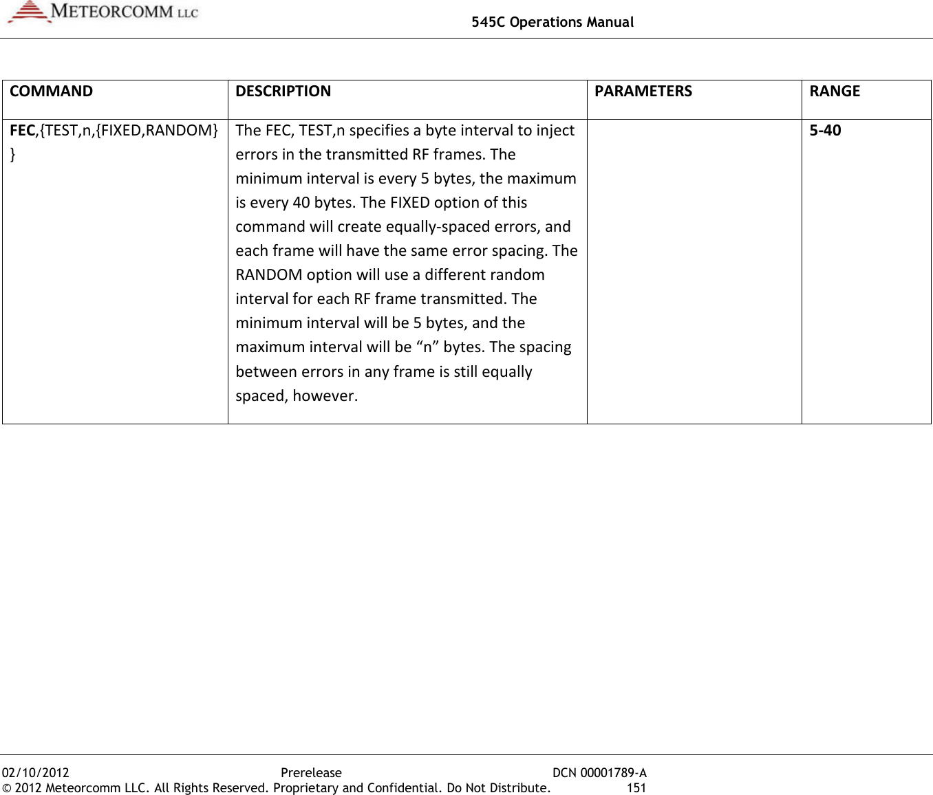
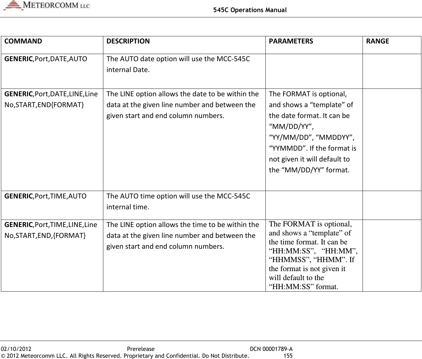
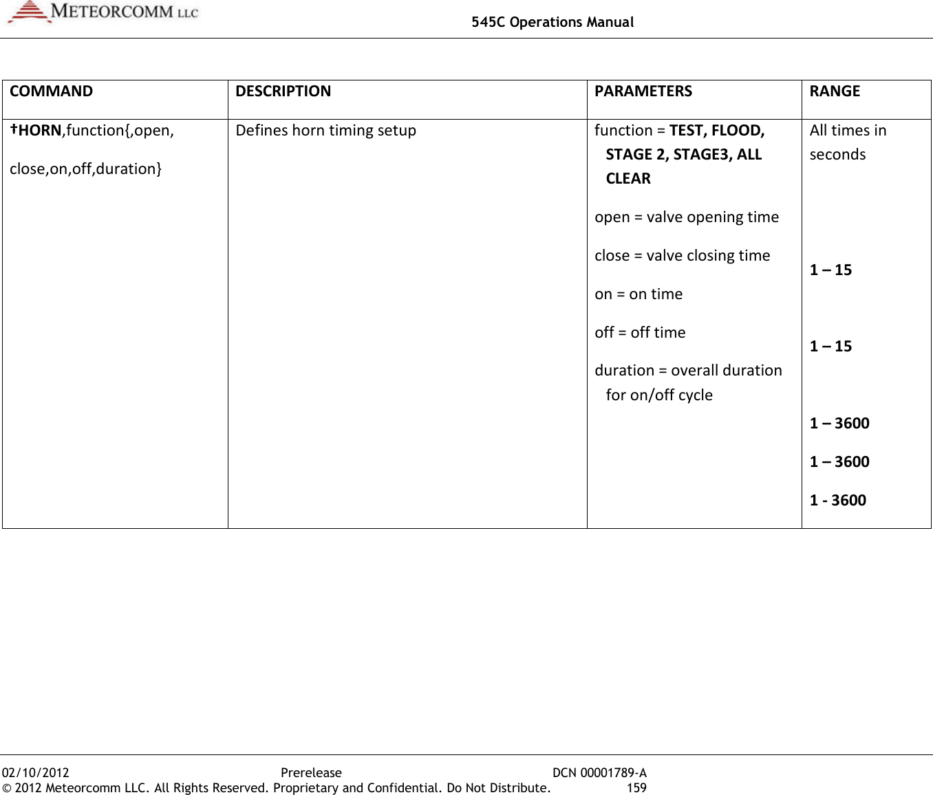
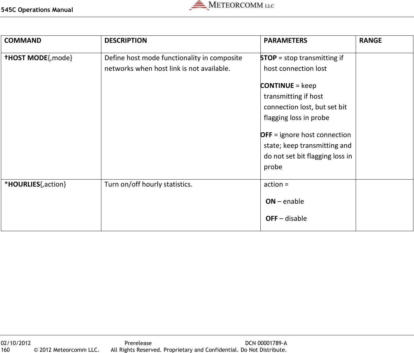
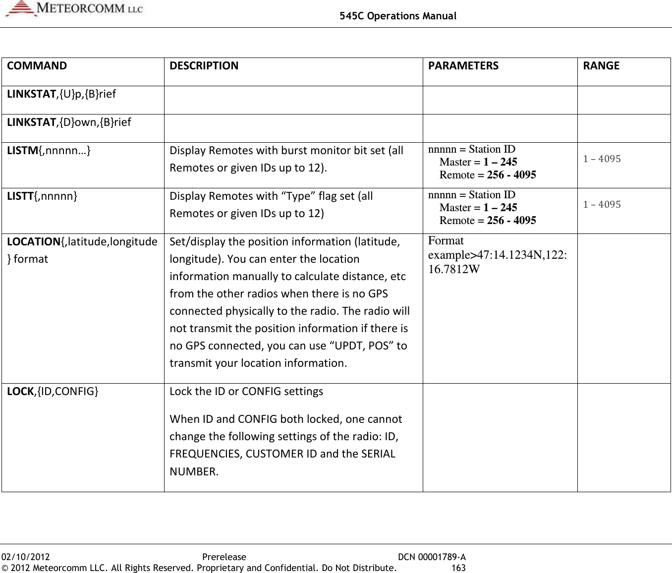
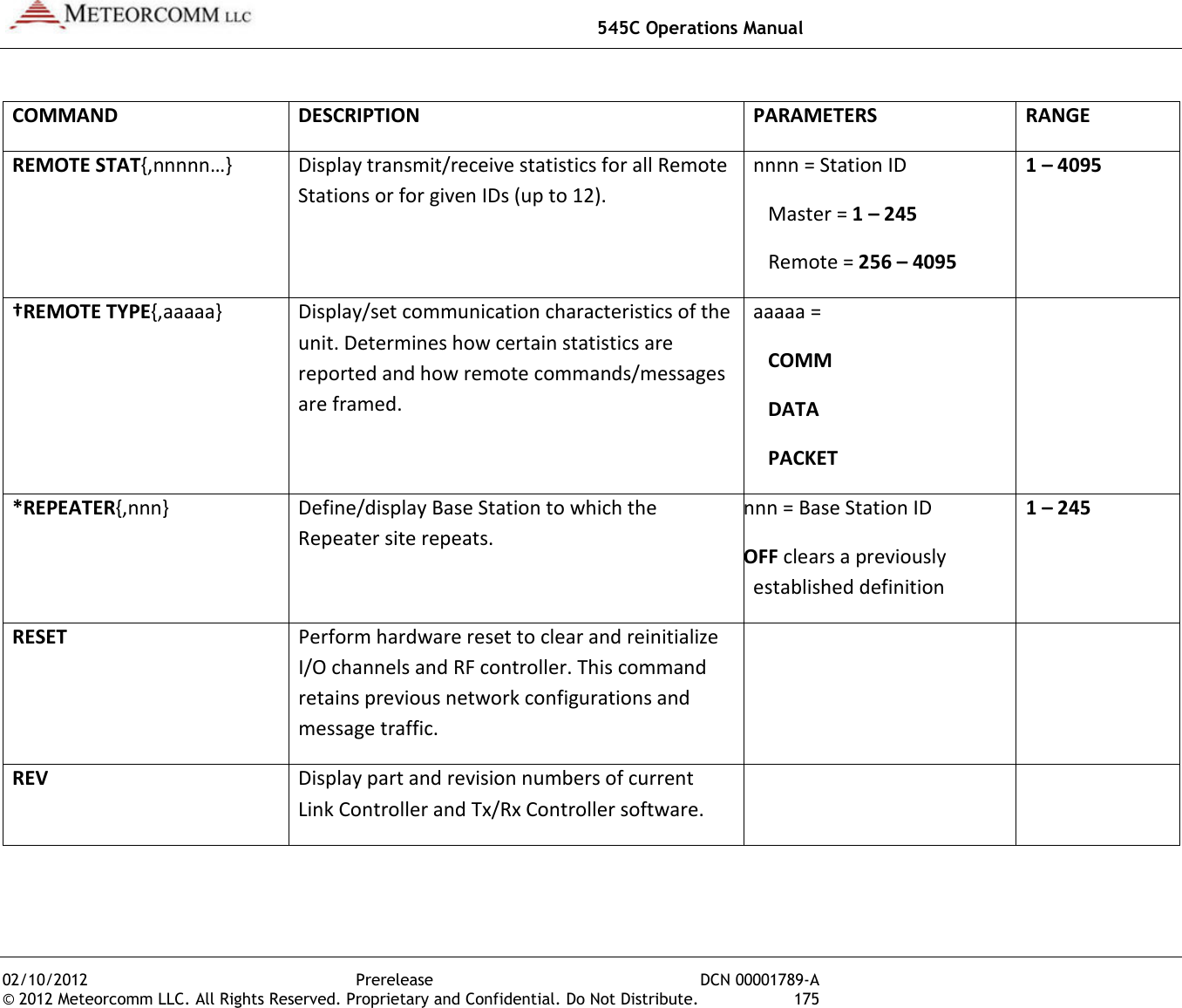
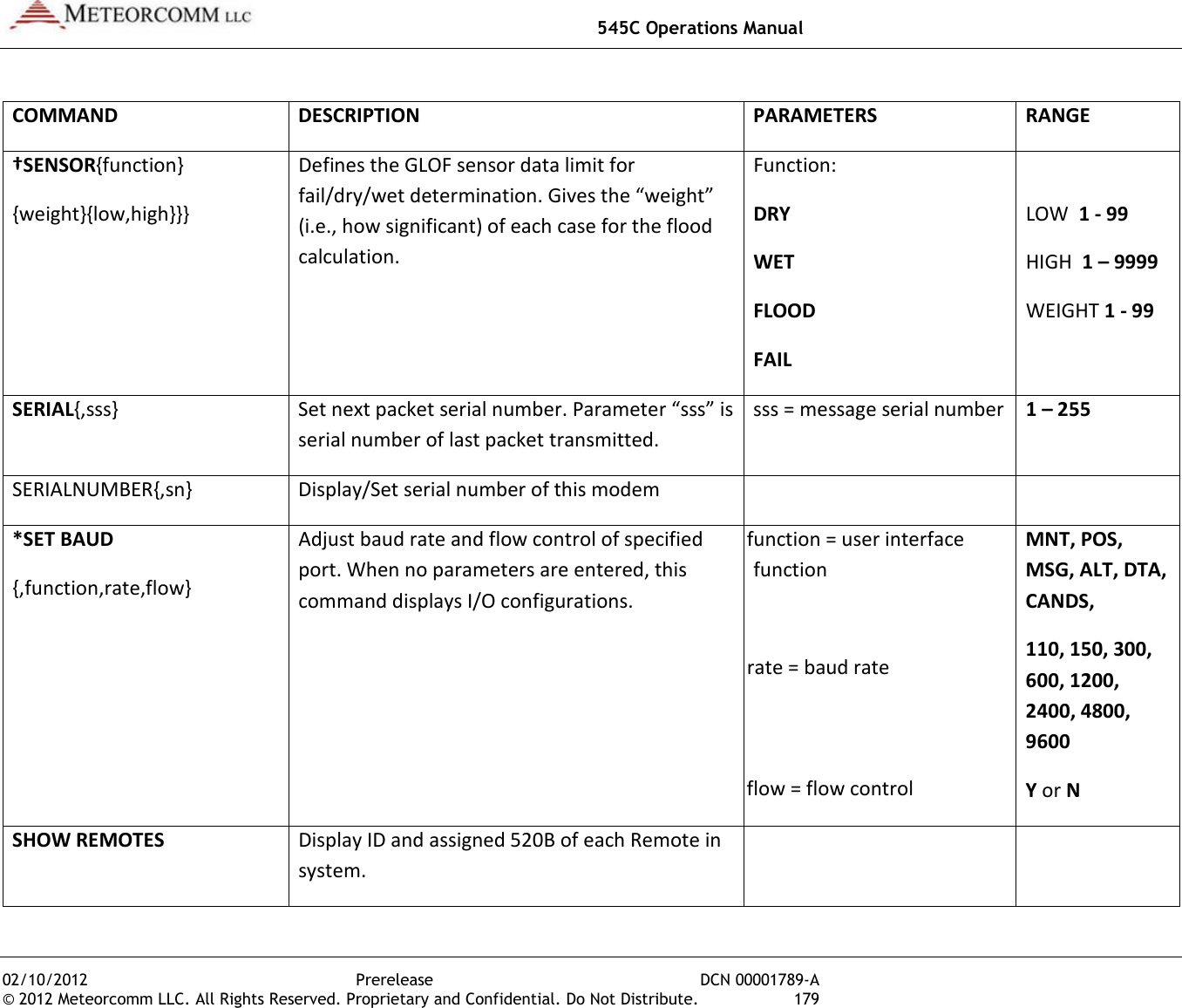
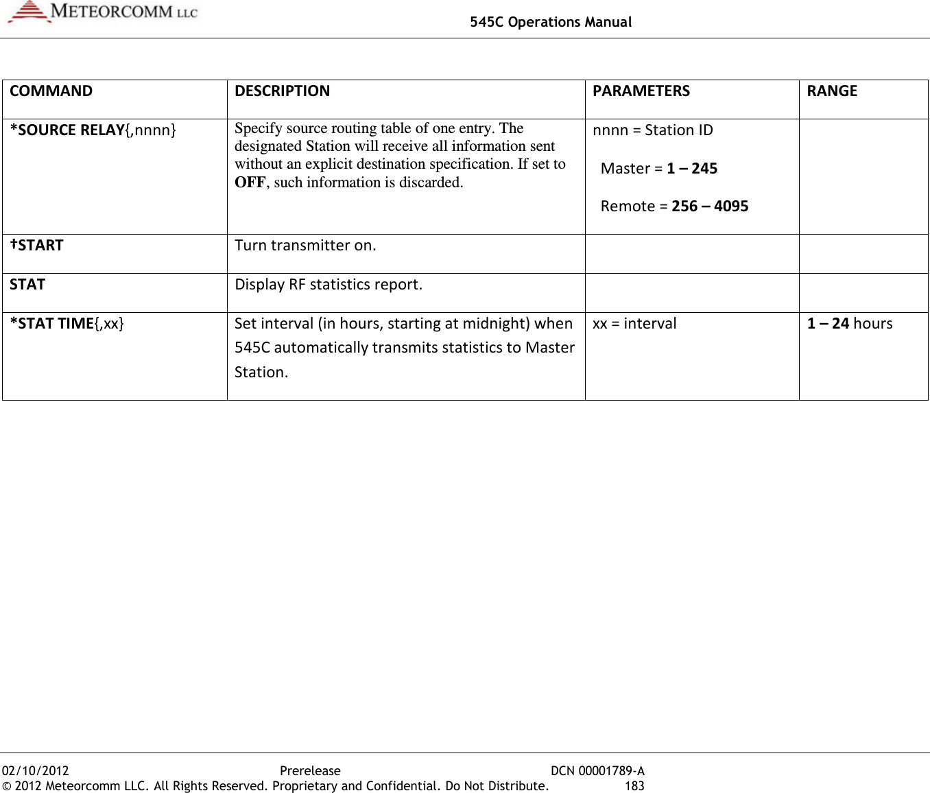
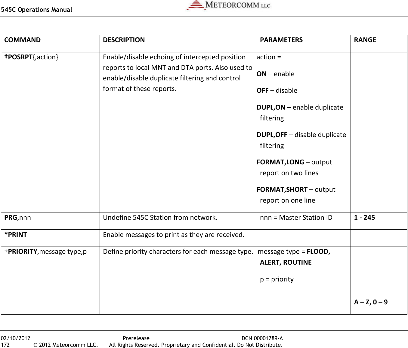
![545C Operations Manual 02/10/2012 Prerelease DCN 00001789-A © 2012 Meteorcomm LLC. All Rights Reserved. Proprietary and Confidential. Do Not Distribute. 165 COMMAND DESCRIPTION PARAMETERS RANGE MESSAGE {,p{,dest1…destn}} Enter a message with text editor. Message priority and destination are optional parameters. After entering message, press [ESC] to queue for transmission. If you do not enter a destination ID, the MCC-545C automatically sends your message to its default destination (set with the DESTINATION command). If you want to use source rounting, enter 0 for the destination. p = priority dest1...destn = destination(s) name = node name nnnn = Station ID Master = 1 – 245 Remote = 256 – 4095 A – Z, 0 – 9 A – Z, 0 – 9 1 – 4095 MM Print current value of RF signal on Receiver in dBm. MODE Print operating mode information. *MODULATION,degree, encoding Set the transmit modulation and data encoding. IMPORTANT MCC-545C modulation must be the same as other units in the network. degree = 90 or 30 encoding = MAN(Manchester), DIFF(Dfferential)](https://usermanual.wiki/Meteorcomm/54505003-01.Users-Manual/User-Guide-1643156-Page-175.png)
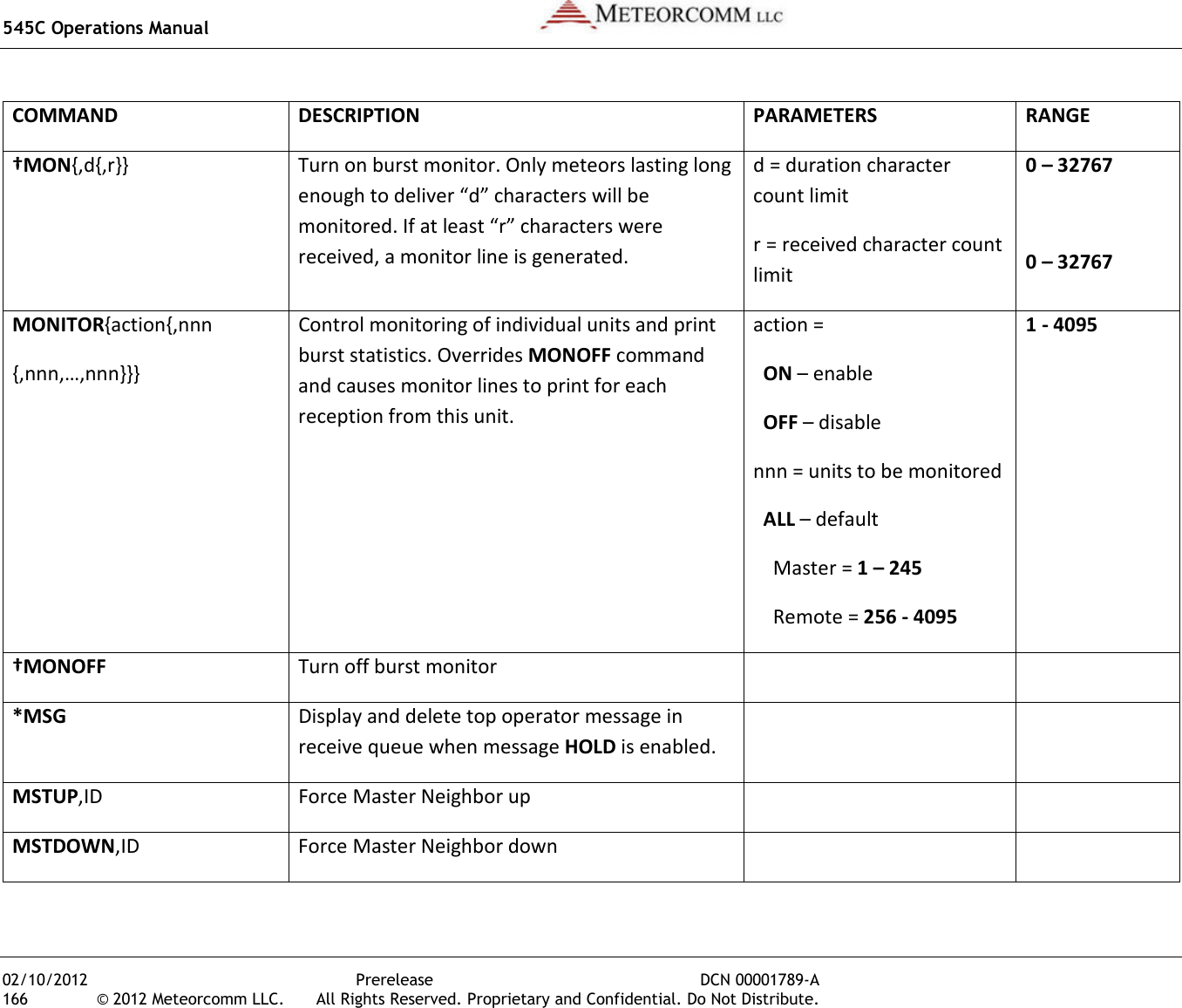
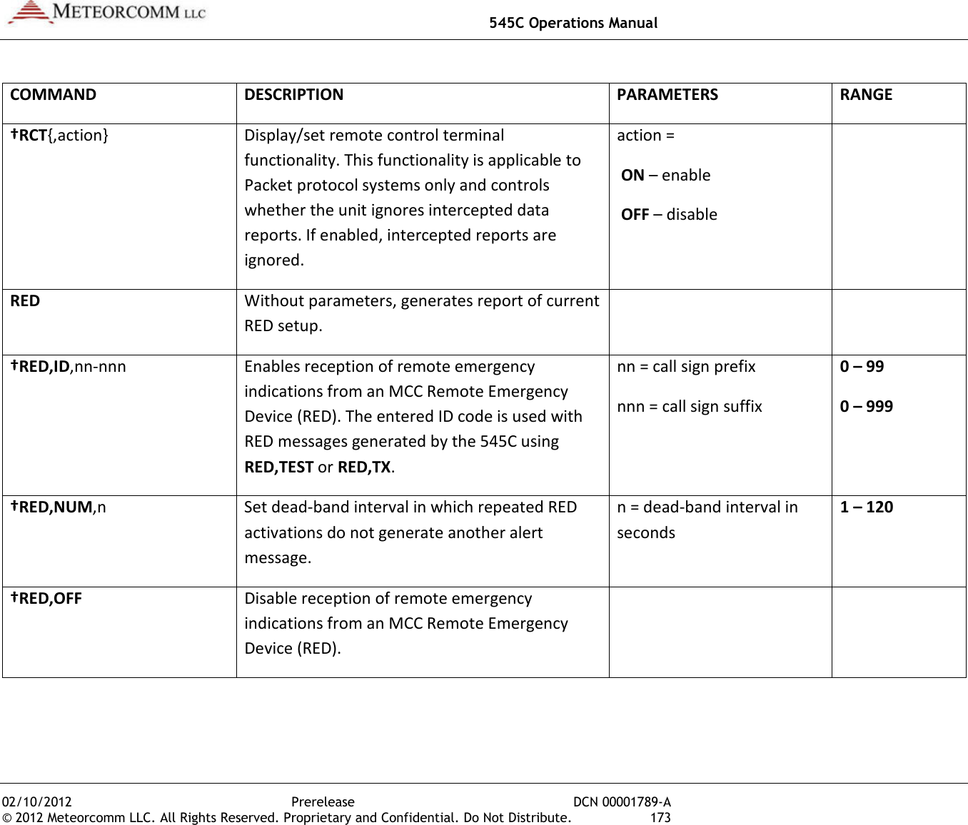
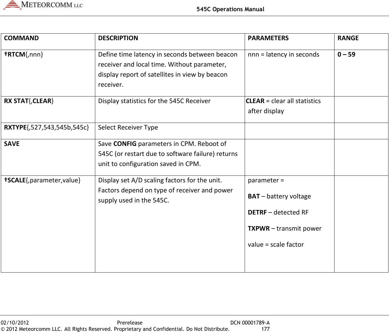
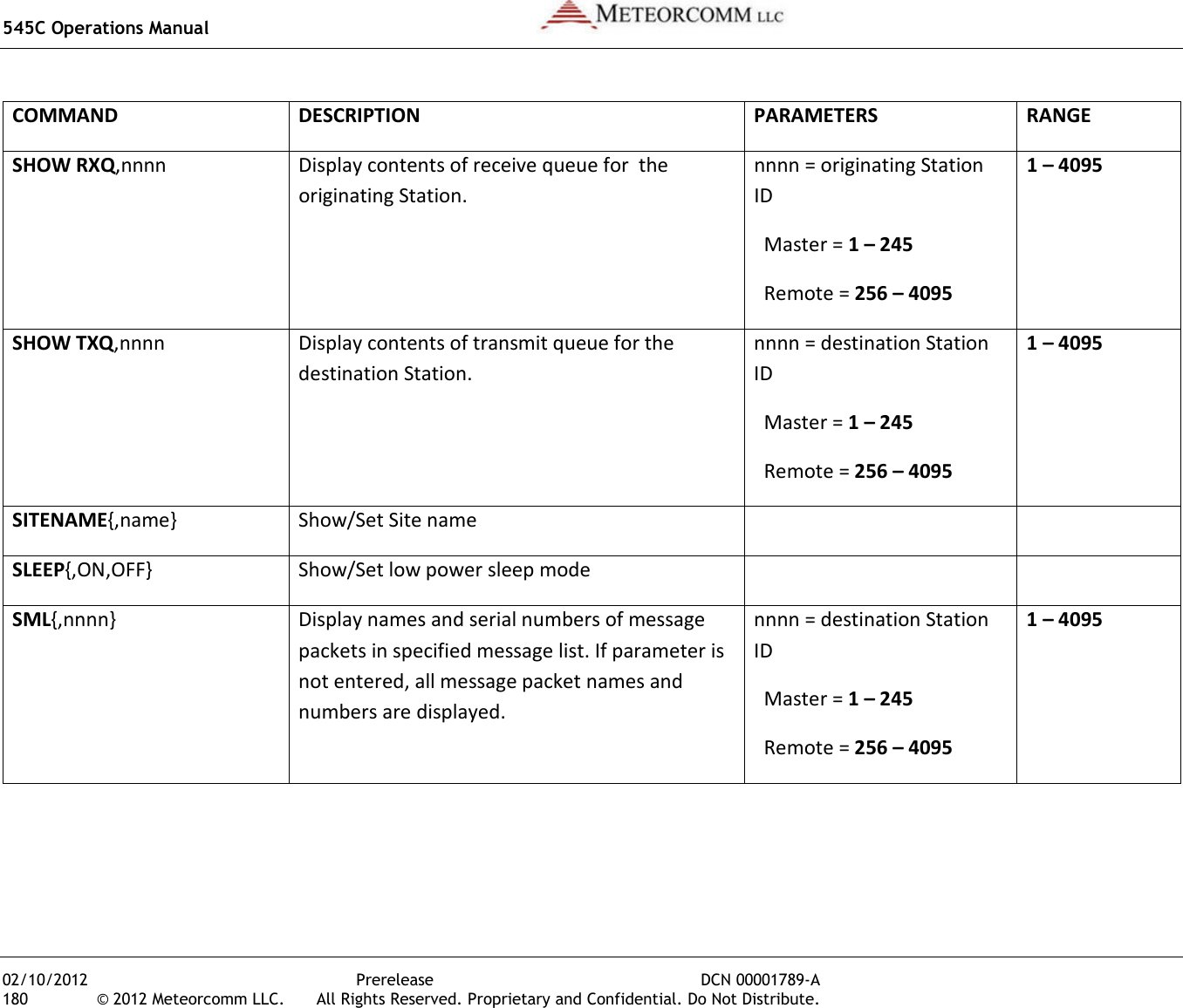
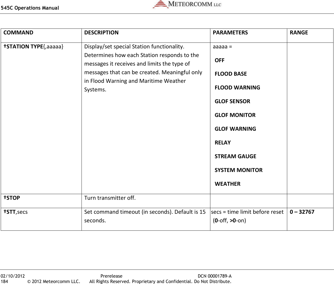
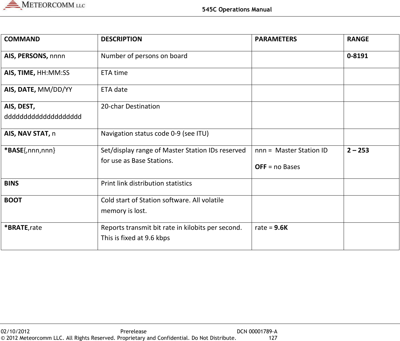
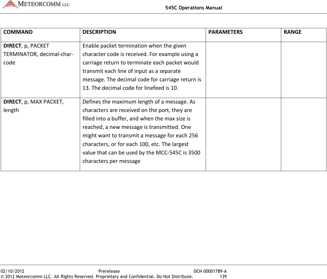
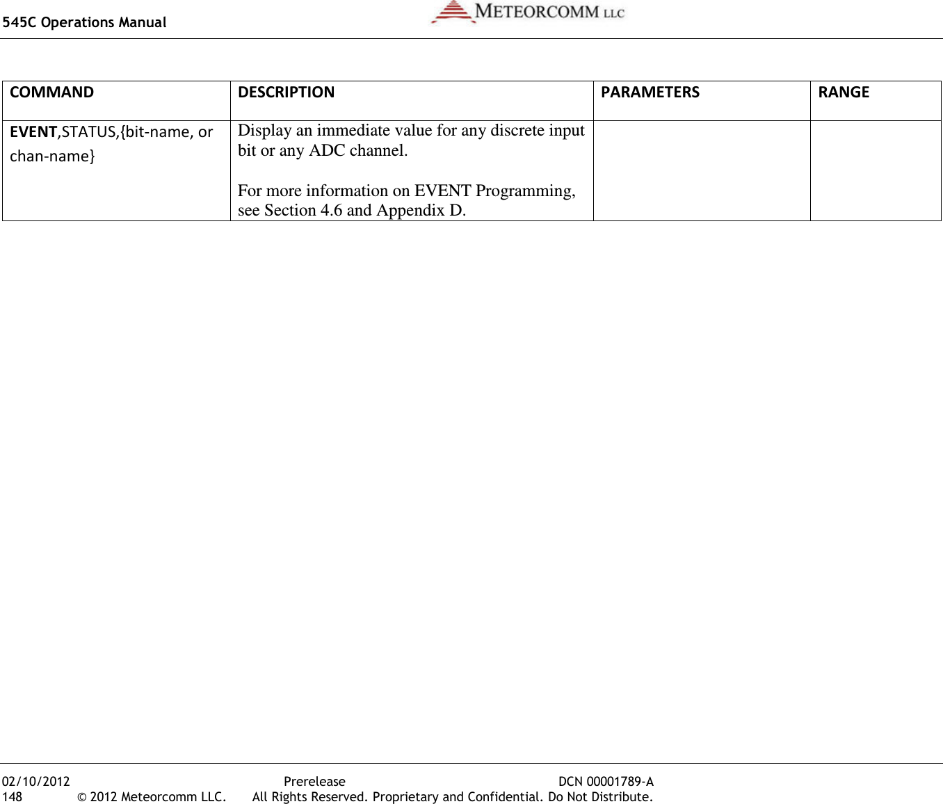
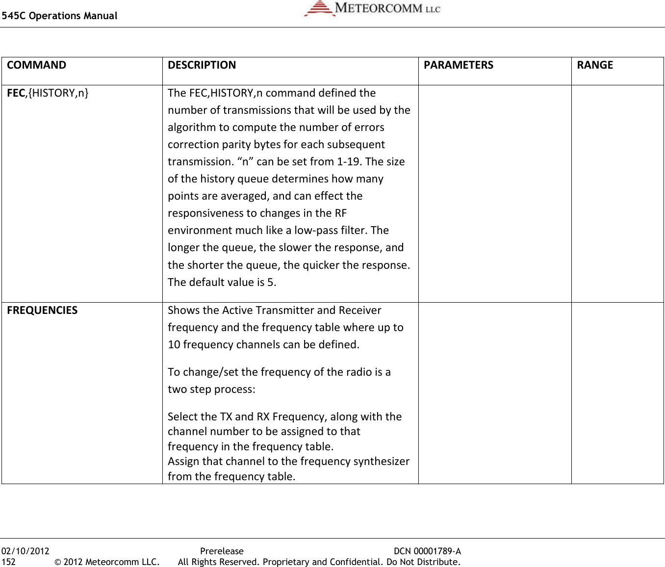
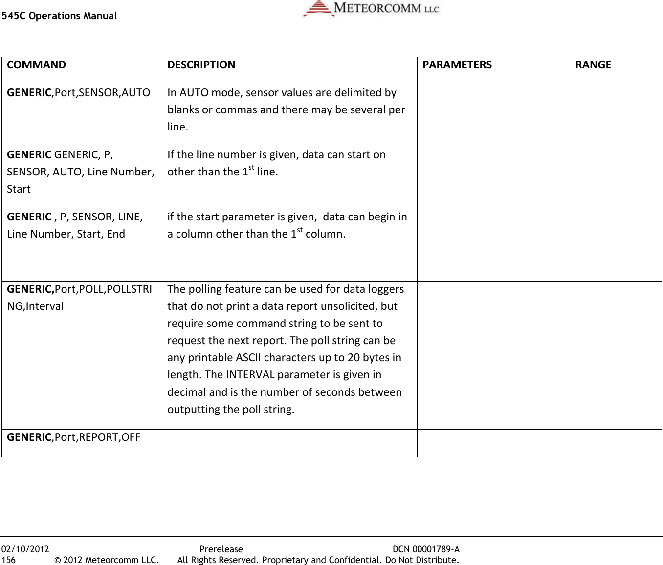
![545C Operations Manual 02/10/2012 Prerelease DCN 00001789-A 174 © 2012 Meteorcomm LLC. All Rights Reserved. Proprietary and Confidential. Do Not Distribute. COMMAND DESCRIPTION PARAMETERS RANGE RED,TEST Simulate a RED test message. Unlike a true RED test button depression, this message is also echoed to the local MNT and DTA ports. RED,TX Simulate a RED alert message. Unlike a true RED alert button depression, this message is also echoed to the local MNT and DTA ports. REMCMD ,p,dest1{,…destn} With the text editor, enter a command to be sent to a Remote. After entering command, press [ESC] to send the command. p = priority dest1…destn destination(s) name = node name nnnn = Station ID Master = 1 – 245 Remote = 256 – 4095 A – Z, 0 – 9 A – Z, 0 – 9 1 – 4095 REG Show Registration data REMDOWN,ID Force Remote Neighbor down n= radio ID REMOTES{,n} Maximum number of remotes REMUP,ID Force Remote Neighbor up](https://usermanual.wiki/Meteorcomm/54505003-01.Users-Manual/User-Guide-1643156-Page-184.png)