Meteorcomm 54505003-01 Packet Data Radio Transceiver - Fixed or Mobile User Manual
Meteorcomm LLC Packet Data Radio Transceiver - Fixed or Mobile Users Manual
Contents
- 1. Users Manual
- 2. RF Users Guide
Users Manual

545C Operations Manual
Document Revision: 1.0
Document Number: 00001789-A

545C Operations Manual
02/10/2012 Prerelease DCN 00001789-A
ii © 2012 Meteorcomm LLC. All Rights Reserved. Proprietary and Confidential. Do Not Distribute.
© 2012 Meteorcomm® LLC. All rights reserved.
Meteorcomm® and ITCNet® are registered trademarks of Meteorcomm LLC and may not be used without
express written permission of Meteorcomm LLC. By downloading, using, or referring to this document or any of
the information contained herein, you acknowledge and agree:
Ownership
This document and the information contained herein are the sole and exclusive property of Meteorcomm LLC
(“MCC”). Except for a limited review right, you obtain no rights in or to the document, its contents, or any
related intellectual property. MCC may, upon written notice, terminate your internal review of this document
and, upon such notice, you will return the original of this document to MCC together with the originals and all
copies of all documents in your possession or under your control that refer or relate to it.
Limited Use and Non-Disclosure
This document contains information that is considered proprietary to MCC. It is protected by copyright, trade
secret, and other applicable laws. This document may not be transmitted, distributed, duplicated, or used,
including, without limitation, the information contained herein, in whole or in part, except as agreed under
separate written agreement with MCC.
Disclaimer of Warranty
This document and all information contained herein or otherwise provided by MCC, and all intellectual property
rights therein, are provided on an “as is” basis. MCC makes no warranties of any kind with respect thereto and
expressly disclaims all warranties of any kind, whether express, implied, or statutory, including but not limited
to warranties of merchantability, fitness for a particular purpose, title, non-infringement, accuracy,
completeness, interference with quiet enjoyment, system integration, or warranties arising from course of
dealing and usage of trade practice.
Assumption of Risk
You are responsible for conducting your own independent assessment of the information contained in this
document (including without limitation schematic symbols, footprints, and layer definitions) and for confirming
its accuracy. You may not rely on the information contained herein, and you agree to validate all such
information by using your own technical experts. Accordingly, you agree to assume sole responsibility for your
review, use of, or reliance on the information contained in this document. MCC assumes no responsibility for,
and you unconditionally and irrevocably release and discharge MCC and its affiliates and their respective
officers, directors, and employees (“MCC Parties”) from, any and all loss, claim, damage, or other liability
associated with or arising from your use of any of the information contained in this document.
Limitation of Liability
In no event shall MCC or the MCC parties be liable for any indirect, incidental, exemplary, special, punitive or
treble, or consequential damages or losses, whether such liability is based on contract, warranty, tort
(including negligence), product liability, or otherwise, regardless as to whether they have notice as to any such
claims.
Hazardous Uses
None of the information contained in this document may be used in connection with the design, manufacture,
or use of any equipment or software intended for use in any fail-safe applications; or any other application
where a failure may result in loss of human life, or personal injury, property damage or have a financial impact;
or in connection with any nuclear facility or activity; or shipment or handling of any hazardous, ultra-
hazardous, or similar materials (“Hazardous Uses”). MCC disclaims all liability of every kind for any Hazardous
Uses, and you release MCC and the MCC Parties from, and shall indemnify MCC and the MCC Parties against,
any such liability, including, but not limited to, any such liability arising from MCC’s negligence.Document
Number: 00001789-A

545C Operations Manual
02/10/2012 Prerelease DCN 00001789-A
© 2012 Meteorcomm LLC. All Rights Reserved. Proprietary and Confidential. Do Not Distribute. iii
Revision History
Revision
Date Description
1.0
0
2
/
10
/2012
Legacy document formatted in 2012 template

545C Operations Manual
02/10/2012 Prerelease DCN 00001789-A
iv © 2012 Meteorcomm LLC. All Rights Reserved. Proprietary and Confidential. Do Not Distribute.
Table of Contents
Acronyms ......................................................................................... viii
1. Introduction .................................................................................. 1
1.1 FleetTrak™ Network ................................................................ 3
1.2 Manual Organization ................................................................ 4
1.3 Related Documents ................................................................. 5
2. RF Safety and Regulatory Information ................................................... 5
2.1 Limiting RF Exposure ............................................................... 5
2.2 RF Interference to Residential Receivers ........................................ 6
2.3 Equipment Modifications ........................................................... 7
3. Description ................................................................................... 7
3.1 General ............................................................................... 7
3.2 Printed Circuit Board Assemblies ............................................... 11
3.2.1 Microprocessor ............................................................. 11
3.2.2 Transceiver ................................................................. 11
3.2.3 Power Amplifier ........................................................... 11
3.3 Microprocessor ..................................................................... 12
3.4 Transceiver ......................................................................... 14
3.5 Pre-Amp, Final Power Amp, and Power Control .............................. 15
3.6 Detailed Specifications ........................................................... 16
3.7 Memory Organization ............................................................. 18
3.7.1 Program Memory (PM) .................................................... 18
3.7.2 Parameter Memory (CPM) ................................................ 18
3.7.3 Data Memory (RAM) ....................................................... 18
3.8 Front Panel LEDs .................................................................. 19
4. INSTALLATION .............................................................................. 20
4.1 Site Selection ...................................................................... 20
4.1.1 External Noise/Interference ............................................. 20
4.1.2 DC Power Source .......................................................... 22
4.1.3 Horizon Angle .............................................................. 23
4.1.4 Antenna Selection ......................................................... 23
4.1.5 Antenna Height ............................................................ 25

545C Operations Manual
02/10/2012 Prerelease DCN 00001789-A
© 2012 Meteorcomm LLC. All Rights Reserved. Proprietary and Confidential. Do Not Distribute. v
4.1.6 Human Exposure To Radio Frequency Electromagnetic Fields ..... 26
4.2 Equipment Installation ........................................................... 26
4.2.1 Mobile Applications ....................................................... 26
4.2.2 Data Collection Applications ............................................ 27
4.2.3 Cable Connections ........................................................ 28
4.3 Power-Up Sequence ............................................................... 34
4.3.1 Operator Terminal ........................................................ 34
4.3.2 Power Connection ......................................................... 34
4.3.3 Initialization Procedures ................................................. 35
4.4 Operational Test Procedure ..................................................... 39
4.4.1 RF Test 39
5. OPERATIONS ................................................................................ 41
5.1 Getting Started .................................................................... 41
5.1.1 XTermW Terminal Emulator ............................................. 41
5.1.2 HELP Command ............................................................ 42
5.1.3 Role-Based Operations ................................................... 42
5.1.4 Unit Identification and Factory Settings ............................... 45
5.1.5 System Time and Date ................................................... 46
5.1.6 System Memory ............................................................ 47
5.2 Station Configuration ............................................................. 49
5.2.1 Configuring the MCC-545C ............................................... 50
5.2.2 Setting frequencies ....................................................... 51
5.2.3 Remote holdoff settings .................................................. 53
5.2.4 Power turn on options .................................................... 53
5.2.5 MCC-545C command schedule list ...................................... 54
5.2.6 Setting Timeout Duration ................................................ 55
5.2.7 Script Files 56
5.2.8 CPU Power Mode .......................................................... 56
5.2.9 Network Configuration ................................................... 57
5.3 Sending and Receiving Messages ................................................ 64
5.3.1 Entering and Deleting Messages ......................................... 66
5.3.2 Editing Messages .......................................................... 68

545C Operations Manual
02/10/2012 Prerelease DCN 00001789-A
vi © 2012 Meteorcomm LLC. All Rights Reserved. Proprietary and Confidential. Do Not Distribute.
5.3.3 Sending Messages ......................................................... 68
5.3.4 Sending Commands ....................................................... 69
5.3.5 Sending Canned Messages ................................................ 70
5.3.6 Receiving Messages ....................................................... 71
5.3.7 Examining Message Status ............................................... 72
5.3.8 Examining and Revising Message Queues .............................. 72
5.4 GPS Position Reporting ........................................................... 73
5.4.1 Position Reporting Commands ........................................... 74
5.4.2 Differential GPS ........................................................... 75
5.4.3 GPS Report Formats ...................................................... 75
5.4.4 GPS Receiver Setup ....................................................... 77
5.4.5 Position Reporting in Subnets ........................................... 77
5.5 Supervisory Control and Data Acquisition ..................................... 78
5.5.1 Sensor Port ................................................................. 78
5.5.2 External Data Loggers .................................................... 81
5.5.3 Direct Mode Protocol ..................................................... 81
5.5.4 Defining Data Relays ...................................................... 87
5.5.5 I/O Port PASSTHRU ........................................................ 88
5.5.6 Internal Sensor Values .................................................... 89
5.5.7 Generic Data Logger ...................................................... 89
5.6 Event Programming ............................................................... 98
5.6.1 Event Programming Overview ........................................... 99
5.6.2 Event Definition .......................................................... 100
5.6.3 Action Definition ......................................................... 103
5.6.4 Programming in Real-Time ............................................. 104
5.6.5 Event Programming Command Summary ............................. 106
5.6.6 Event Programming Command Details ................................ 107
5.6.7 Action Details ............................................................. 116
5.6.8 Reading Internal Sensor Values ........................................ 118
5.6.9 Common Command Parameters ........................................ 118
5.6.10 ADC Channel Names ..................................................... 120
5.7 Command Summary .............................................................. 121

545C Operations Manual
02/10/2012 Prerelease DCN 00001789-A
© 2012 Meteorcomm LLC. All Rights Reserved. Proprietary and Confidential. Do Not Distribute. vii
Appendices ................................................................................ 191

545C Operations Manual
02/10/2012 Prerelease DCN 00001789-A
viii © 2012 Meteorcomm LLC. All Rights Reserved. Proprietary and Confidential. Do Not Distribute.
Table of Figures
Figure 1: MCC 545C Packet Data Radio ........................................ 2
Figure 2: FleetTrak™ network diagram ........................................ 3
Figure 3: MCC-545C outline drawing ........................................... 9
Figure 4:Exploded view of the MCC-545C ................................... 10
Figure 5:MCC-545C block diagram ............................................ 13
Figure 6: MCC-545C front panel LEDs ........................................ 19
Figure 7: Single dipole antenna ............................................... 24
Figure 8: 3-Element YAGI antenna ........................................... 24
Figure 9: Remote station antenna height for meteor burst .............. 25
Figure 10: Typical remote station with 3-element YAGI antenna ....... 27
Figure 11: MCC-545C cable connections ..................................... 28
Figure 12: MCC-545C power connector pins ................................ 29
Figure 13: MCC-545C I/O port cable ......................................... 30
Figure 14: Message flow and associated commands ....................... 65
Figure 15: Position report formats ........................................... 76
Figure 16: Event programming block diagram .............................. 99
Table of Tables
Table 1:MCC-545C general specifications ................................... 16
Table 2:MCC-545C receiver specifications .................................. 16
Table 3: MCC-545C transmitter specifications.............................. 17
Table 4:MCC-545C microprocessor specifications .......................... 17
Table 5: CO-AX cable loss (50 MHz) .......................................... 25
Table 6: Role-based operations ............................................... 43
Table 7: MCC-545C commands ............................................... 121
Acronyms
A/D
Analog
-
to
-
Digital
ACK
Acknowledgement

545C Operations Manual
02/10/2012 Prerelease DCN 00001789-A
© 2012 Meteorcomm LLC. All Rights Reserved. Proprietary and Confidential. Do Not Distribute. ix
ADC
Analog
-
to
-
Digital Converter
AUX
Auxiliary Port
AVL
Automatic Vehicle Location
BPSK
Binary Phase Shift Keying
CR
Carriage Return
CSMA
Carrier Sense Multiple Access
DAC
Digital
-
to
-
Analog Converter
DMC
Data, Management and Control
DSP
Digital Signal Processing
DTA
Data Port
ELOS
Extended
-
Line
-
of
-
Sight
ETE
End
-
to
-
End Acknowledgement
GMSK
Gausian Minimum Shift Keying
GPS
Global Positioning System
KBPS
Kilo (1,000) bits per seconds
LED
Light Emitting Diode
LOS
Line
-
of
-
Sight
MBC
Meteor Burst Communication
MBCS
Meteor Burst Communication
System
MCC
Meteor Communications Corporation
MNT
Maintenance Port
NMEA
National Marine Electronic Association
PC
Personal Computer
PCA
Printed Circuit Assembly
PCB
Printed Circuit Board
RAM
Random Access Memory
RF
Radio Frequency
RTCM
Radio Technical
Commission for Maritime Services
RX
Receive
SCADA
Supervisory Control and Data Acquisition
SDATA
Sensor Data
SNP
System Network Parameter
SPDT
Single Pole Double Throw
TDMA
Time Division Multiple Access
TX
Transmit

545C Operations Manual
02/10/2012 Prerelease DCN 00001789-A
x © 2012 Meteorcomm LLC. All Rights Reserved. Proprietary and Confidential. Do Not Distribute.
UPDT
Update
UTC
Universal Time
Clock
VSWR
Voltage Standing Wave Ratio
XTermW
Terminal Emulator

545C Operations Manual
02/10/2012 Prerelease DCN 00001789-A
© 2012 Meteorcomm LLC. All Rights Reserved. Proprietary and Confidential. Do Not Distribute. 1
1. Introduction
This manual outlines the operation of the MCC-545C Packet Data Radio
through software revision 6.87.
The MCC-545C Packet Data Radio is used in MCC’s FleetTrak™ network.
This chapter briefly describes this network application; refer also to
Appendix F for a complete discussion of MCC Network Interoperability.
In addition to information and instructions for line of sight applications,
this manual also contains information regarding meteor burst master
and remote station installation and refers to antennas used in those
installations that apply to use of the MCC-545B or other MCC models.
Please refer to the tables in the MCC-545C RF Energy Exposure Guide
for lists of antenna types suitable for use in vertically-polarized line
of sight applications of the MCC-545C.
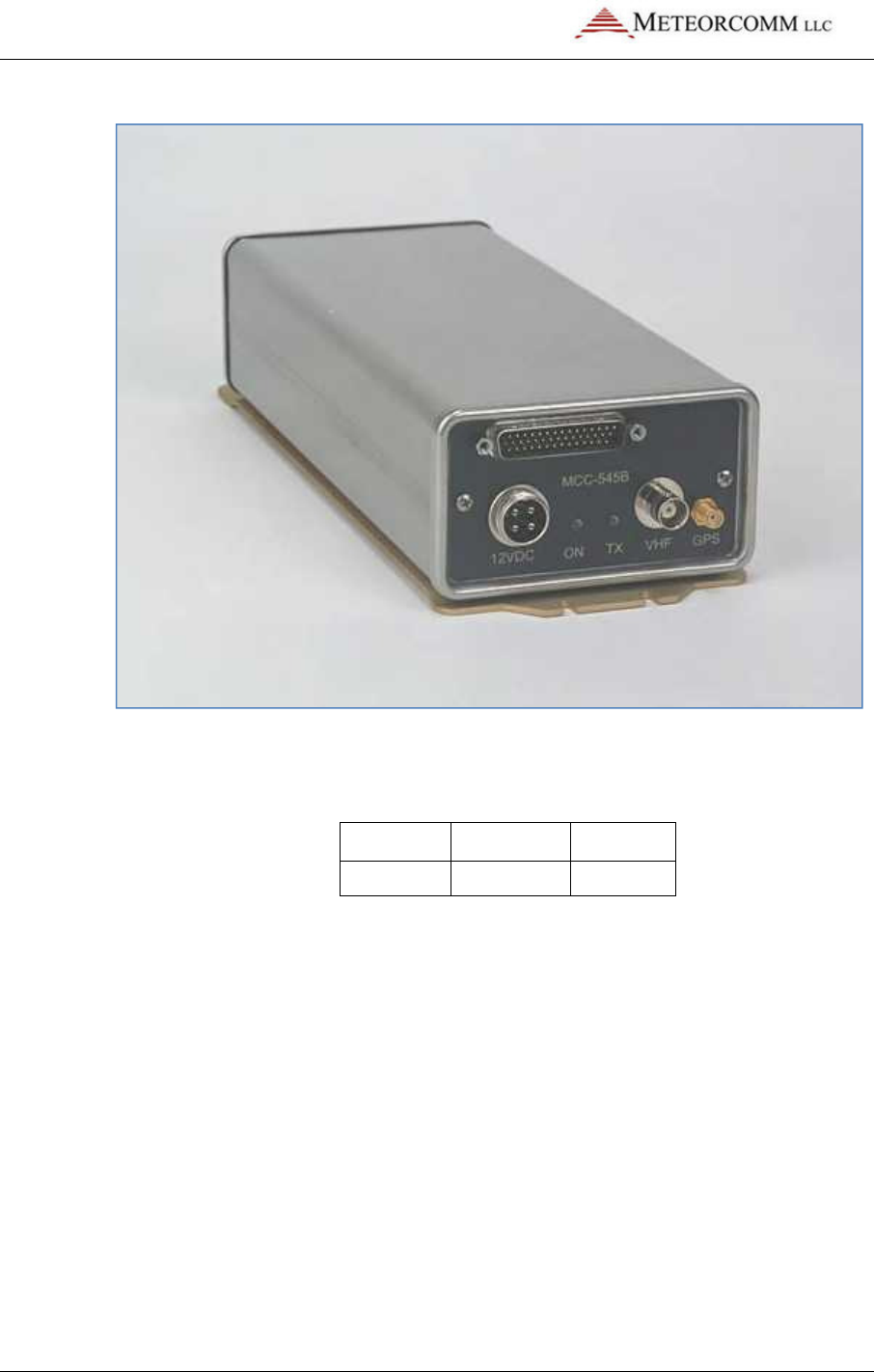
Each MCC-545C features rugged construction and is packaged in a
stainless steel, weather-resistant enclosure that measures 10.6"L x
4.0"W x 2.42"H and weighs 3.5 pounds, as shown in Figure 1.1.
545C Operations Manual
02/10/2012 Prerelease DCN 00001789-A
2 © 2012 Meteorcomm LLC. All Rights Reserved. Proprietary and Confidential. Do Not Distribute.
Figure 1: MCC 545C Packet Data Radio
The MCC-545C radio is frequency synthesized and uses a GMSK
modulation scheme with selectable data rates, as shown below.
Model No.
Modulation
Data rate
MCC-545C
GMSK
9.6 kbps
The MCC-545C has an embedded 32-bit controller for managing all the
network functions associated with a packet switched data network and
for interfacing to a variety of peripheral devices. In addition, it has a
built-in test capability that automatically monitors the operating
integrity of the unit at all times. This feature also eliminates the need
for any special test equipment during the installation phase. A laptop,
palmtop, or equivalent is required to initialize and operate the MCC-
545C packet radio.
545C Operations Manual
02/10/2012 Prerelease DCN 00001789-A
© 2012 Meteorcomm LLC. All Rights Reserved. Proprietary and Confidential. Do Not Distribute. 3
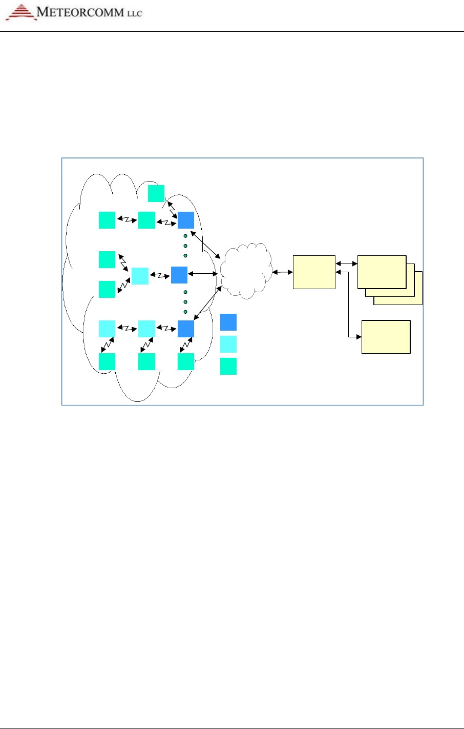
1.1 FleetTrak™ Network
The FleetTrak™ network is used for applications that require the
position of mobile resources to be reported in real-time and at varying
update rates. The FleetTrak network is shown in Figure 1.2.
Figure 2: FleetTrak™ network diagram
The FleetTrak™ network is comprised of Base Stations, Repeaters, and
Remote Stations. The MCC-545C can be programmed to operate as any
of these three distinct station types. The FleetTrak™ network is used for
position reporting in mobile applications (AVL), fixed site data
collection (SCADA), and messaging.
The FleetTrak™ network operates line-of-sight using groundwave and
uses an LOS protocol for channel access. In an LOS network, there is
always an RF connection path between adjacent stations, and stations
transmit data whenever they have something to send. These
transmissions use CSMA (carrier sense multiple access) to gain channel
access and to prevent RF signal collisions.
The range of communication by groundwave is primarily determined by
diffraction around the curvature of the earth, atmospheric diffraction,
and tropospheric propagation. These ranges are successfully extended
by MCC from 50-100 miles through the use of robust protocols, sensitive
receivers, and short packetized messages.
CLIENT’S
OFFICES
DATA
NETWORK
DATA CENTER
OR
HOST
CLIENT’S
OFFICES
B
R
M
BASE STATION
REMOTE STATION (FIXED OR MOBILE)
REPEATER STATION
M B
M
M
M
M
RB
R
MMM
R B
ELOS RF NETWORK
OTHER
CLIENTS

545C Operations Manual
02/10/2012 Prerelease DCN 00001789-A
4 © 2012 Meteorcomm LLC. All Rights Reserved. Proprietary and Confidential. Do Not Distribute.
1.2 Manual Organization
There are 5 major sections in this manual, plus a number of appendices:
Section 2.0 RF Safety and Regulatory Information
This section provides important information regarding antenna
installations and means to safely limit exposure to RF radiation.
Section 3.0 Description
This section provides both a physical description and a functional
description of each module in an MCC-545C. The detailed technical
specifications are provided for each printed circuit board assembly
(PCA), as well as the organization of the unit’s computer memory.
Section 4.0 Installation
This section covers site selection and general installation guidelines,
including instructions for cabling, antenna and power source
connections. Power up procedures, initialization and functional test
procedures are described that should be performed prior to placing the
MCC-545C on-line within the network.
Section 5.0 Operation
This section describes all the operating procedures for the MCC-545C.
All commands and operational parameters are described for data
collection, supervisory control, messaging, and interpreting system
operational statistics. It also contains a list of all MCC-545C commands.
Appendices include:
Appendix A Command Printouts
Appendix B Factory Default Parameters
Appendix C Loading a Script File
Appendix D Programming an Event
Appendix E MCC Hardware and Sample Part Numbers

02/10/2012
© 2012 Meteorcomm LLC. All Right
Appendix F
1.3
Related Documents
Additional documents and application notes that may be helpful in the
operation of a MCC
documents (and more recent updates, if available), can be obtained
from MCC or downloaded from MCC’s web site, www.meteorcomm.com.
1. XTermW –
Operation of the
Windows, Octob
2. DMC –
Data Monitor and Control, DMC 6.313, Users Manual, January
14, 2002
3. MBNET 200
–
4. MCC-
520B/C Master Station
Burst Communications Terminal, Rev. K,
5.
CR10X Data Acquisition
January 25, 2000
6.
Wireless Data
2.
RF Safety and Regulatory Information
2.1
Limiting RF Exposure
Please refer to the
information regarding safe distances that must be maintained between
personnel and energized transmitting antennas.
The information in the
Exposure Guide”
when followed, limit human exposure to radio frequency energy to
acceptable levels.
protection to
both employees and the general public.
545C Operations Manual
Prerelease
hts Reserved.
Proprietary and Confidential. Do Not Distribu
Interoperability With Other MCC Products
Related Documents
Additional documents and application notes that may be helpful in the
operation of a MCC
-54
5C Packet Data Radio are given below
documents (and more recent updates, if available), can be obtained
from MCC or downloaded from MCC’s web site, www.meteorcomm.com.
Operation of the
XTermW
Terminal Emulation Program for
Windows, Octob
er 22, 1999
Data Monitor and Control, DMC 6.313, Users Manual, January
–
a complete list of all commands and printouts
520B/C Master Station
– Operations of the MCC-
520B/C Meteor
Burst Communications Terminal, Rev. K,
December 2002
CR10X Data Acquisition
–
Application Note: CR10X Data Acquisition,
January 25, 2000
Wireless Data
–
MCC Wireless Data Services, EDT 11039, January 2000
RF Safety and Regulatory Information
Limiting RF Exposure
Please refer to the
MCC-545C RF Energy Exposu
re Guide
information regarding safe distances that must be maintained between
personnel and energized transmitting antennas.
The information in the
MCC-5454C
RF Energy Exposure Guide
Exposure Guide”
is determine
d from FCC and Industry Canada rules that
when followed, limit human exposure to radio frequency energy to
acceptable levels.
O
beying these limits will provide reasonable
both employees and the general public.
545C Operations Manual
DCN 00001789-A
ibute.
5
Interoperability With Other MCC Products
Additional documents and application notes that may be helpful in the
5C Packet Data Radio are given below
. These
documents (and more recent updates, if available), can be obtained
from MCC or downloaded from MCC’s web site, www.meteorcomm.com.
Terminal Emulation Program for
Data Monitor and Control, DMC 6.313, Users Manual, January
a complete list of all commands and printouts
520B/C Meteor
Application Note: CR10X Data Acquisition,
MCC Wireless Data Services, EDT 11039, January 2000
re Guide
for specific
information regarding safe distances that must be maintained between
RF Energy Exposure Guide
“RF
d from FCC and Industry Canada rules that
when followed, limit human exposure to radio frequency energy to
beying these limits will provide reasonable
545C Operations Manual
02/10/2012
6
© 2012 Meteorcomm LLC.
This radio
is intended for installation and use by
full knowledge of their exposure and can exercise control over their
exposure to meet FCC and IC limits. This radio device is not intended
for use by consumers or the general population.
• Table 1 i
n the RF Exposure Guide list
distances to be maintained between the general pu
operational
transmitter antenna for
applications.
•
Table 2 in the RF Exposure Guide list
distanc
es to be maintained between
transmitter antenna for two antenna types for fixed applications.
Once the authorized ERP, antenna gain and the losses from feed line,
connectors and any inline RF f
must be evaluated and if necessary,
ensure that the authorized ERP and RF exposure requirements are met.
Example ERP calculations are provided further below.
Caution:
automatically at any time when functioning as a data
radio.
beginning any service or maintenance. Remove the
antenna and connect a dummy load during testing.
2.2 RF Interference
to Residential Receivers
NOTICE TO USER: This device complies with part 15 of the FCC Rules.
Operation is subject to the condition that this device does not cause
harmful interference.
NOTE: This equipment has been tested and found to comply with the
lim
its for a Class B digital device, pursuant to Part 15 of the FCC Rules.
These limits are designed to provide reasonable protection against
harmful interference in a residential installation. This equipment
Prerelease
DCN
.
All Rights Reserved. Proprietary and Confidential. Do
is intended for installation and use by
employees who have
full knowledge of their exposure and can exercise control over their
exposure to meet FCC and IC limits. This radio device is not intended
for use by consumers or the general population.
n the RF Exposure Guide list
s
the calculated lateral
distances to be maintained between the general pu
blic and an
transmitter antenna for
two antenna types
fo
applications.
Table 2 in the RF Exposure Guide list
s
the calculated lateral
es to be maintained between
employees and an operational
transmitter antenna for two antenna types for fixed applications.
Once the authorized ERP, antenna gain and the losses from feed line,
connectors and any inline RF f
ilters are known, the transmitter power
must be evaluated and if necessary,
attenuated
to a value that will
ensure that the authorized ERP and RF exposure requirements are met.
Example ERP calculations are provided further below.
Caution:
Be aware that
a transmitter may operate
automatically at any time when functioning as a data
radio.
Always disable the transmitter prior to
beginning any service or maintenance. Remove the
antenna and connect a dummy load during testing.
to Residential Receivers
NOTICE TO USER: This device complies with part 15 of the FCC Rules.
Operation is subject to the condition that this device does not cause
harmful interference.
NOTE: This equipment has been tested and found to comply with the
its for a Class B digital device, pursuant to Part 15 of the FCC Rules.
These limits are designed to provide reasonable protection against
harmful interference in a residential installation. This equipment
DCN
00001789-A
Do Not Distribute.
employees who have
full knowledge of their exposure and can exercise control over their
exposure to meet FCC and IC limits. This radio device is not intended
the calculated lateral
blic and an
fo
r mobile
the calculated lateral
employees and an operational
transmitter antenna for two antenna types for fixed applications.
Once the authorized ERP, antenna gain and the losses from feed line,
ilters are known, the transmitter power
to a value that will
ensure that the authorized ERP and RF exposure requirements are met.
a transmitter may operate
automatically at any time when functioning as a data
Always disable the transmitter prior to
beginning any service or maintenance. Remove the
antenna and connect a dummy load during testing.
NOTICE TO USER: This device complies with part 15 of the FCC Rules.
Operation is subject to the condition that this device does not cause
NOTE: This equipment has been tested and found to comply with the
its for a Class B digital device, pursuant to Part 15 of the FCC Rules.
These limits are designed to provide reasonable protection against
harmful interference in a residential installation. This equipment

02/10/2012
© 2012 Meteorcomm LLC. All Right
generates and can radiate radio frequency energy
and used in accordance with the instructions, may cause harmful
interference to radio communications. However, there is no guarantee
that interference will not occur in a particular installation. If this
equipment does cause harmfu
reception, which can be determined by turning the equipment off and
on, the user is encouraged to try to correct the interference by one or
more the following measures:
•
Reorient or relocate
• Incre
ase the separation between the equipment and receiver.
•
Connect the equipment into an outlet on a circuit different from
that to which the receiver is connected.
•
Consult the dealer or an experienced radio/TV technician for help.
2.3
Equipment Modifications
3.
Description
3.1 General
The MCC-
545C Packet
communications from fixed or mobile sites to a central Host
used for data collection, position reporting, sending and receiving
messages, or other custom applications
consumption
(<1 watt) makes it ideal for operating in remote locations
where only solar power is available.
The MCC-
545C also has a built
external data logger is not required for those installations that have less
545C Operations Manual
Prerelease
hts Reserved.
Proprietary and Confidential. Do Not Distribu
generates and can radiate radio frequency energy
and, if not installed
and used in accordance with the instructions, may cause harmful
interference to radio communications. However, there is no guarantee
that interference will not occur in a particular installation. If this
equipment does cause harmfu
l interference to radio or television
reception, which can be determined by turning the equipment off and
on, the user is encouraged to try to correct the interference by one or
more the following measures:
Reorient or relocate
the receiving antenna.
ase the separation between the equipment and receiver.
Connect the equipment into an outlet on a circuit different from
that to which the receiver is connected.
Consult the dealer or an experienced radio/TV technician for help.
Equipment Modifications
Caution:
Any changes or modifications to this
equipment not expressly approved by the party
responsible for compliance (in the respective country
of use) could void the user’s authority to operate the
equipment.
Description
545C Packet
Data Radio provides packet switched
communications from fixed or mobile sites to a central Host
used for data collection, position reporting, sending and receiving
messages, or other custom applications
.
The unit's low standby
(<1 watt) makes it ideal for operating in remote locations
where only solar power is available.
545C also has a built
-
in data collection capability so that an
external data logger is not required for those installations that have less
545C Operations Manual
DCN 00001789-A
ibute.
7
and, if not installed
and used in accordance with the instructions, may cause harmful
interference to radio communications. However, there is no guarantee
that interference will not occur in a particular installation. If this
l interference to radio or television
reception, which can be determined by turning the equipment off and
on, the user is encouraged to try to correct the interference by one or
ase the separation between the equipment and receiver.
Connect the equipment into an outlet on a circuit different from
Consult the dealer or an experienced radio/TV technician for help.
Any changes or modifications to this
equipment not expressly approved by the party
responsible for compliance (in the respective country
of use) could void the user’s authority to operate the
Data Radio provides packet switched
communications from fixed or mobile sites to a central Host
. It can be
used for data collection, position reporting, sending and receiving
The unit's low standby
-power
(<1 watt) makes it ideal for operating in remote locations
in data collection capability so that an
external data logger is not required for those installations that have less

545C Operations Manual
02/10/2012 Prerelease DCN 00001789-A
8 © 2012 Meteorcomm LLC. All Rights Reserved. Proprietary and Confidential. Do Not Distribute.
than 10 sensors. A special break-out cable is supplied by MCC to access
the following I/O capability:
Inputs Outputs
6 analogs
0-5V
4-20 mA (with external 250 ohm resistor)
10 bit accuracy/resolution
2 Form C
SPDT Relays
4 ON/OFF, optically isolated
1 GPS, NMEA compatible
3 RS-232 Ports
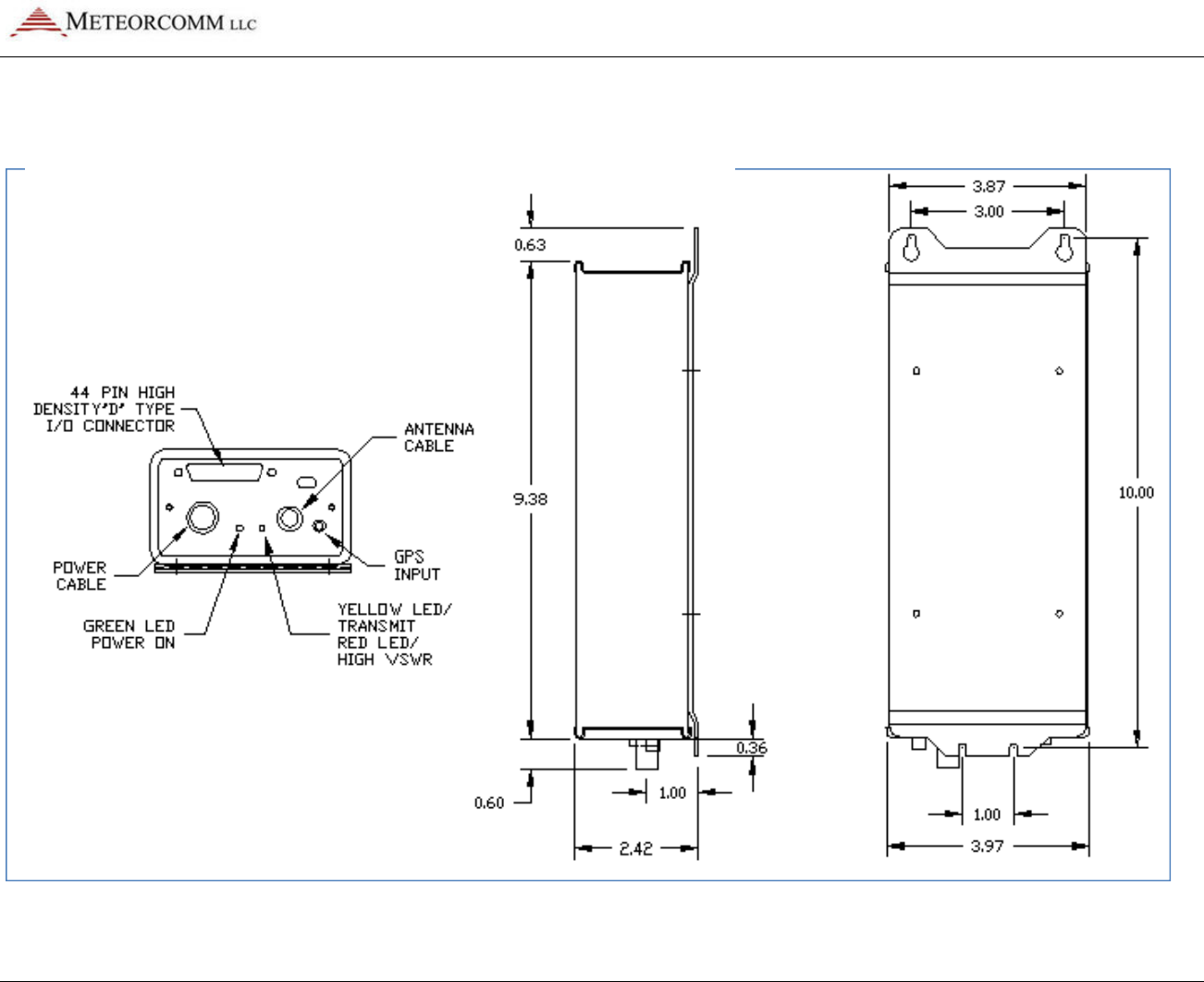
An outline drawing and an exploded view of the chassis are shown in
Figures 2.1 and 2.2.
545C Operations Manual
02/10/2012 Prerelease DCN 00001789-A
© 2012 Meteorcomm LLC. All Rights Reserved. Proprietary and Confidential. Do Not Distribute. 9
Figure 3: MCC-545C outline drawing
545C Operations Manual
02/10/2012 Prerelease DCN 00001789-A
10 © 2012 Meteorcomm LLC. All Rights Reserved. Proprietary and Confidential. Do Not Distribute.
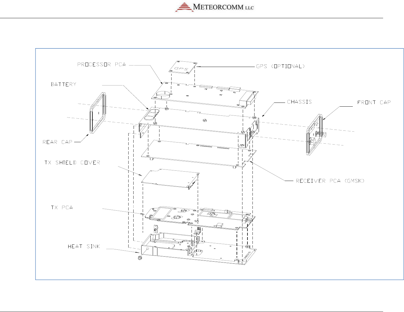
Figure 4:Exploded view of the MCC-545C

545C Operations Manual
02/10/2012 Prerelease DCN 00001789-A
© 2012 Meteorcomm LLC. All Rights Reserved. Proprietary and Confidential. Do Not Distribute. 11
3.2 Printed Circuit Board Assemblies
The MCC-545C contains three printed circuit board assemblies as shown
in Figure 2.2.
3.2.1 Microprocessor
The low-power 32-bit microprocessor controller performs the radio
control, link, and network protocol functions. This assembly also
contains a digital signal processor (DSP) and digital-to-analog converter
(DAC) for generating the in-phase (I) and quadrature-phase (Q) base
band signals for generating the GMSK RF signal.
3.2.2 Transceiver
The selectable-rate transceiver uses a vector phase modulator (+13DBm
output) and frequency synthesizers to produce 9.6 kbps.
3.2.3 Power Amplifier
Note: The nominal RF power amplifier rating of the MCC-545C is 100W
or 50 dBm. The output power is calibrated at the factory at the
expected operating frequency. Measured power values may vary up to 1
dB from rated power, up to 51 dBm or 125W over the frequency range
of the radio.
The multi-stage power amplifier includes a 2 watt, 2-stage preamplifier;
a 100 watt, solid-state, 2-stage power amplifier; and a power switch.
A 12-channel GPS receiver may be mounted on the processor board as
an optional subassembly.
All components are soldered in place using surface mount technology.
As an option, the boards can be conformal coated with an acrylic
encapsulate that contains a tropicalizing, anti-fungal agent to provide
additional protection against moisture and contamination.

545C Operations Manual
02/10/2012 Prerelease DCN 00001789-A
12 © 2012 Meteorcomm LLC. All Rights Reserved. Proprietary and Confidential. Do Not Distribute.
3.3 Microprocessor
The microprocessor is a Motorola-based, embedded processor located
on a single PCB that contains:
• 512K x 16 of non-volatile flash memory for program storage
• 512K x 16 of non-volatile flash memory for parameter storage
• 1024K x 8 of static RAM for data storage (optionally 2048K x 8)
• 3 External RS-232 I/O ports
• Internal TTL GPS port
• Transmitter communication port
• Receiver communication port
• 10-bit 11 channel A/D converter (6 channels are available for
external sensors)
• Real-time clock
• Power fail detection circuitry
• Digital Signal Processor with D/A converters
• 6 Optically isolated digital inputs
• 2 Form C Relay Outputs with a current rating of 2 amps
All I/O ports are RS-232 compatible and can be programmed to adapt to
various customer protocols. The DATA port contains full flow control
hardware lines.
545C Operations Manual
02/10/2012 Prerelease DCN 00001789-A
© 2012 Meteorcomm LLC. All Rights Reserved. Proprietary and Confidential. Do Not Distribute. 13
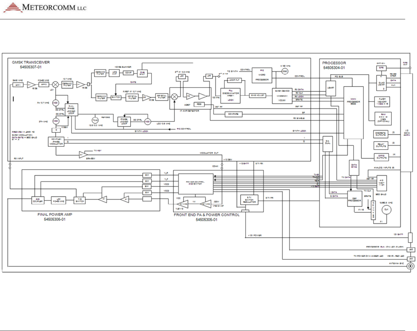
Figure 5:MCC-545C block diagram
The A/D converter measures TX forward and reverse power, battery voltage, antenna noise voltage,
transmitter board temperature, and 6 channels of 0-5V external sensor inputs. In –03 or later versions the
internal nickel metal hydride battery (3.6V) can also be read.

545C Operations Manual
02/10/2012 Prerelease DCN 00001789-A
14 © 2012 Meteorcomm LLC. All Rights Reserved. Proprietary and Confidential. Do Not Distribute.
An internal lithium ion battery is used to maintain the internal real time
clock and battery backed RAM. This battery operates the clock in a
power down state for a period of approximately 6 months. This battery
should be removed if the unit is stored for extended periods of time.
In -03 or later versions of the units, the lithium ion battery has been
replaced with a rechargeable nickel metal hydride battery. This battery
is located at the rear of the unit with Velcro. (You have to open the
rear lid to get access to it.) A short jumper is used to connect the
battery to the processor board. This jumper should be removed if the
unit is stored for long periods of time (longer than 2 months). The
battery must be connected before the unit will start operating.
3.4 Transceiver
The transceiver assembly contains a receiver, transmit and receive
frequency synthesizers, and a modulator. The MCC-545C receiver and
modulator support 9.6 kbps Gaussian Minimum Shift Keying (GMSK).
GMSK Receiver
• Input bandpass filter (37-50 MHz )
• RF amplifier (17 dB)
• Low pass image filter (Fc=50 MHz)
• Mixer
• IF amplifiers and filters (10.7 MHz)
• Noise blanker
• Mixer, 2nd IF filter and amplifier (100 kHz), and RSSI circuit
• Phase lock loop frequency discriminator
• GMSK bit detector and clock generator
Synthesizer (1st and 2nd local oscillator and transmit oscillator)
• Reference Oscillator (12.8 MHz +/- 2.5 PPM)
• Tx phase lock loop (74-100 MHz output, 20 kHz steps)
(86-92 MHz, 20 kHz steps in FCC ID: BIB54505003-01)
• A divide by 2 circuit (37-50 MHz output, 10 kHz steps)
(43-46 MHz, 10 kHz steps in FCC ID: BIB54505003-01)

545C Operations Manual
02/10/2012 Prerelease DCN 00001789-A
© 2012 Meteorcomm LLC. All Rights Reserved. Proprietary and Confidential. Do Not Distribute. 15
• Rx 1st local oscillator phase lock loop (47.7-60.7 MHz output, 10
kHz steps limited to 53.7 – 56.7 MHz in FCC ID: BIB54505003-01)
• Rx 2nd local oscillator phase lock loop (10.6 MHz)
• PIC Microcontroller
GMSK Modulator
• DSP digital baseband GMSK generator
• I and Q DACs
• I/Q Vector Phase Modulator (GMSK)
• Pre amplifier (+13 dBm output)
All components are mounted on an 8.5" by 3.5" two-sided printed circuit
board. All components are surface mounted.
3.5 Pre-Amp, Final Power Amp, and Power Control
This board contains two low-level amplifiers that amplify the +13 dBm
(10 mW) signal from the modulator to the 2 watts required by the final
power amplifier. A special power switch is used to control the rise and
fall times of the RF power output. A duty cycle limiter circuit limits the
duty cycle of the power amplifier to 16%. A temperature sensor is also
located on this board for monitoring the internal temperature of the
MCC-545C. This temperature reading may be transmitted to the Host for
maintenance purposes.
The 100 watt power amplifier is mounted inside an aluminum enclosure
to provide RF shielding between the low level phase lock loop
synthesizers and the high power output. This board contains a T/R
switch for half-duplex operation, a harmonic low pass filter, and a dual
directional coupler for power level control. The coupler measures
forward and reverse power. If the VSWR exceeds 3.0:1 the power
amplifier automatically shuts down. The power amplifier’s parameters
are also transmitted to the Host for maintenance purposes.
A switching regulator power supply provides 5.7 volts for the processor
and transceiver boards.

545C Operations Manual
02/10/2012 Prerelease DCN 00001789-A
16 © 2012 Meteorcomm LLC. All Rights Reserved. Proprietary and Confidential. Do Not Distribute.
3.6 Detailed Specifications
The detailed specifications for each of the printed circuit board
assemblies are given in Tables 2.1 through 2.4.
Table 1:MCC-545C general specifications
Characteristic Specification
Dimensions
10.6"L x 4.0"W x 2.42"H
Weight
3.5 lbs.
Temperature Range
-
30
°
to 60
°
C (
-
22
°
to 140
°
F)
Power Requirements
12 V
DC
Nominal (10
-
14 V
DC
)
Standby: 80 ma (Continuous)
Transmit: 25 Amps Nominal (100 msec)
Table 2:MCC-545C receiver specifications
Characteristic Specification
Frequency
37
-
50 MHz
or 43
-
46 MHz
Synthesized 10 kHz steps
Frequency accuracy, calibrated: ±1ppm
Frequency stability: ±5ppm -30°to +60°C
Modulation: Type
Rate
Format
GMSK
9.6 kbps
NRZ
Noise Figure
≤
7
dB
Sensitivity: Bit Error Rate < 10
-
3
at 9.6
kbps
≤
-
114
dBm
IF Bandwidth (3/80 dB)
13/40 kHz typical
RF Bandwidth (3 dB)
13 MHz typical
Signal Acquisition Time
< 5 ms
3
rd
Order Intercept Point
>
-
4 dBm
Image Response Attenuation
> 70 dB minimum
Spurious Response Attenuation
> 70 dB minimum
SP Threshold
Adjustable from
–
115 to
–
106 dBm
Triggered by DET RF and Demodulator
Lock
Noise Blanker
> 20 dB Reduction in Impulse Noise

545C Operations Manual
02/10/2012 Prerelease DCN 00001789-A
© 2012 Meteorcomm LLC. All Rights Reserved. Proprietary and Confidential. Do Not Distribute. 17
I/O
MCC Standard (Refer to Section 3.2.3)
Table 3: MCC-545C transmitter specifications
Characteristic Specification
Frequency
37
-
50 MHz (FCC ID: BIB54505001
-
01)
43-46 MHz (FCC ID: BIB54505003-01)
Synthesized 10 kHz steps
Frequency accuracy, calibrated: ±1 ppm
Frequency stability: ±5 ppm -30 to +60C
RF Power Output, Nominal
100 Watts into 50 ohms
at 12 V
DC
Input
Load VSWR
< 2:1 Rated Power
Harmonic and Spurious Levels
-
70 dB
TIA
-
603C
Modulation: Type
Rate
Format
GMSK
9.6 kbps
NRZ
Spurious
> 70 dB
TIA
-
603C
Transmit Modulation Spectrum
TIA
-
603C (FCC
Mask C
–
20 kHz channels)
Tx Duty Cycle Firmware limit:
Hardware limit:
10% max averaged over 5 minutes
RF PA self-limits at > 16% in one minute
T/R Switch
Solid
-
State
Switching Time < 100 microseconds
I/O
MCC
Standard (Refer to Section 3.2.3)
High VSWR Protection
Withstands Infinite VSWR
Table 4:MCC-545C microprocessor specifications
Characteristic Specification
Main Processor
Motorola MC68332FC 32
-
bit Embedded
Controller
Memory: Program Storage
Parameter Storage
Data Storage
512K x 16 non
-
volatile Flash memory
512K x 16 non-volatile Flash memory
1024K x 8 static RAM (optional 2048K x
8)

545C Operations Manual
02/10/2012 Prerelease DCN 00001789-A
18 © 2012 Meteorcomm LLC. All Rights Reserved. Proprietary and Confidential. Do Not Distribute.
Switches: SW1
System Reset, Momentary
3.7 Memory Organization
The MCC-545C has three types of memory:
3.7.1 Program Memory (PM)
The Program memory is non-volatile Flash (512K x 16). It contains the
MBNET200 image software, bootstrap, configuration, and application
software. These programs are installed at the MCC facilities at the time
of shipment. The information stored in the Program memory is referred
to as “factory defaults”.
3.7.2 Parameter Memory (CPM)
The Parameter memory is non-volatile Flash (512K x 16). It contains the
configuration data for the unit such as the customer number, the serial
number and ID of the MCC-545C, and the authorized FCC frequencies it
may use. This information is normally programmed into the unit prior to
shipment. The Script files are also stored in Parameter memory, either
at the MCC facilities or on site.
3.7.3 Data Memory (RAM)
The Data memory is volatile RAM (1024K x 8) and has battery backup.
Date, time, executable programs, command parameters, and program
dynamic data (messages, data, position, etc.) are all stored in RAM
during normal operations. As an option, the Data memory may be
expanded to 2048K x 8.
During normal operation, the MCC-545C software uses the data and
configuration parameters stored in RAM. If the data information in RAM
is lost or corrupted, for whatever reason, the configuration parameters
can be retrieved from Parameter memory. This ensures uninterrupted
operation.

545C Operations Manual
02/10/2012 Prerelease DCN 00001789-A
© 2012 Meteorcomm LLC. All Rights Reserved. Proprietary and Confidential. Do Not Distribute. 19
The RAM contents will be lost under the following conditions:
• The Boot command is issued.
• The Reset button (SW1) is depressed. (Remove the rear panel to
locate SW 1.)
• The internal backup battery fails or is disconnected. (In -02 units,
remove jumper JP1 while the external power is turned off to the
unit. In -03 or later units, remove connector J1.)
• The watchdog timer initiates a restart.
The software will detect these events and will recopy the parameters
and configuration values from Parameter memory back into RAM when
operation is resumed.
If the contents of Parameter memory become invalid the unit will revert
to the factory defaults in Program memory.
3.8 Front Panel LEDs
The two LEDs on the front panel provide the operator with a quick
assessment of the unit’s operational status.
Figure 6: MCC-545C front panel LEDs
LED COLOR STATUS
ON
Green; flashes every 5 seconds
Power is on and the processor is running
TX
ON LED

545C Operations Manual
02/10/2012 Prerelease DCN 00001789-A
20 © 2012 Meteorcomm LLC. All Rights Reserved. Proprietary and Confidential. Do Not Distribute.
TX
Yellow; flashes during
transmission
Red; flashes during transmission
Off
Transmit power is normal and VSWR is below
3.0:1
Transmit power is normal but VSWR is
greater than 3.0:1
Transmit power is off or below normal
4. INSTALLATION
Site selection and general installation guidelines are provided in this
section, including instructions for cabling, antenna and power source
connections. Power up procedures, initialization and functional test
procedures are described that should be performed prior to placing the
MCC-545C on-line within the network.
4.1 Site Selection
There are 5 important factors to consider in selecting an optimum site:
1. External noise/interference
2. DC power source
3. Horizon angle
4. Antenna type
5. Antenna height
4.1.1 External Noise/Interference
Noise and signal interference can reduce the performance of the MCC-
545C. The most common sources of noise and interference are as
follows:
• Cosmic Noise
• Power Line Noise
• Automobile Ignition Noise
• Computer-Generated Interference
• External Signal Interference

02/10/2012
© 2012 Meteorcomm LLC. All Right
Cosmic Noise
Cosmic noise is the limiting noise factor in a meteor burst system
noise is generated by star systems in the galaxy and is frequency
dependent.
The noise is approximat
and 13 dB above thermal at 50 MHz
the highest when the antennas are pointed directly at the center of the
galaxy and lowest when they are pointed at right angles to it
variations of 3 to 4 dB can be expected
one that is limited only by cosmic noise.
Power Line Noise
One of the main sources of man
Noise on these lines is generated by high voltage bre
on power line hardware such as transformers and insulators
can be seen with an oscilloscope at the Receiver IF test point as a series
of spikes that occur every 8 msec (1/60 Hz) or every 10 msec (1/50 Hz)
The level of the spik
floor.
The number of spikes can vary, depending upon the level of
interference, from one or two every 8
8-10 msec.
The impulse noise blanker in the MCC
a
mount of this type of noise
increase, the effectiveness of the blanker is reduced
site always, check the IF test point with a scope to determine the level
of the power line noise interference
noise be avoided for an optimum site
well away from power lines.
Note
power lines to reduce noise. Call the local utility in case of severe
noise.
Automobile Ignition Noise
Automobile ignition noise is generated by all gasoline engines and is a
result of the high voltage required to fire the spark plugs
noise is similar to power line noise, with the exception that it does not
have the regular 8
Computer-
Generated Interference
545C Operations Manual
Prerelease
hts Reserved.
Proprietary and Confidential. Do Not Distribu
Cosmic noise is the limiting noise factor in a meteor burst system
noise is generated by star systems in the galaxy and is frequency
The noise is approximat
ely 15 dB above thermal at 40 MHz
and 13 dB above thermal at 50 MHz
.
This noise is diurnal in nature
the highest when the antennas are pointed directly at the center of the
galaxy and lowest when they are pointed at right angles to it
variations of 3 to 4 dB can be expected
.
An optimal meteor burst site is
one that is limited only by cosmic noise.
Power Line Noise
One of the main sources of man
-
made noise is high voltage power lines
Noise on these lines is generated by high voltage bre
akdown occurring
on power line hardware such as transformers and insulators
can be seen with an oscilloscope at the Receiver IF test point as a series
of spikes that occur every 8 msec (1/60 Hz) or every 10 msec (1/50 Hz)
The level of the spik
es is much higher than the normal background noise
The number of spikes can vary, depending upon the level of
interference, from one or two every 8
-
10 msec to several dozen every
The impulse noise blanker in the MCC
-
545C removes a large
mount of this type of noise
.
However, as the number of spikes
increase, the effectiveness of the blanker is reduced
.
When setting up a
site always, check the IF test point with a scope to determine the level
of the power line noise interference
. It is mand
atory that power line
noise be avoided for an optimum site
.
Try to place the receiver antenna
well away from power lines.
Note
:
Power companies are required to properly maintain their
power lines to reduce noise. Call the local utility in case of severe
noise.
Automobile Ignition Noise
Automobile ignition noise is generated by all gasoline engines and is a
result of the high voltage required to fire the spark plugs
.
noise is similar to power line noise, with the exception that it does not
have the regular 8
-
10 msec period associated with power line noise.
Generated Interference
545C Operations Manual
DCN 00001789-A
ibute.
21
Cosmic noise is the limiting noise factor in a meteor burst system
. This
noise is generated by star systems in the galaxy and is frequency
ely 15 dB above thermal at 40 MHz
This noise is diurnal in nature
. It is
the highest when the antennas are pointed directly at the center of the
galaxy and lowest when they are pointed at right angles to it
. Daily
An optimal meteor burst site is
made noise is high voltage power lines
.
akdown occurring
on power line hardware such as transformers and insulators
. This noise
can be seen with an oscilloscope at the Receiver IF test point as a series
of spikes that occur every 8 msec (1/60 Hz) or every 10 msec (1/50 Hz)
.
es is much higher than the normal background noise
The number of spikes can vary, depending upon the level of
10 msec to several dozen every
545C removes a large
However, as the number of spikes
When setting up a
site always, check the IF test point with a scope to determine the level
atory that power line
Try to place the receiver antenna
Power companies are required to properly maintain their
power lines to reduce noise. Call the local utility in case of severe
Automobile ignition noise is generated by all gasoline engines and is a
.
Auto ignition
noise is similar to power line noise, with the exception that it does not
10 msec period associated with power line noise.
545C Operations Manual
02/10/2012
22
© 2012 Meteorcomm LLC.
All computers and printers contain high
spurious signals throughout the 37
if any of these signals couple into the antenna at the MCC
frequency.
To minimize this type of interference, try to keep the
antenna away from computers by at least 100
noise blanker does not suppress computer
External Signal Interference
This type of interference occurs whenever another transmitter produces
harmonics at the receiver center frequency of the MCC
nu
lling and spatial separation can be used to reduce this type on
interference.
Note:
With XTermW installed (see Section 3.3), the STAT
command can be used to determine the site antenna noise levels.
Ideally, the background noise levels should be less than
4.1.2
DC Power Source
The MCC-
545C requires a 12 VDC power source
current is about 80 mA
amps for 100 msec
the average current requ
without GPS option) when operating at a normal duty cycle of 10%
automobile battery provides an excellent power source.
If there is no AC power available, a solar panel can be used to charge
the battery. The
size of the solar panel is determined by the solar
radiation available at the location of the site
USA, a 30 watt solar panel will suffice
winter temperatures are below freezing, a larger panel will ha
used.
Consult MCC or contact the solar panel manufacturer to perform
this calculation for you and make a recommendation.
The power cable between the battery and the MCC
shorter than 10 feet and rated at #14 AWG or lower
3.2.3.1 for more details.)
Prerelease
DCN
.
All Rights Reserved. Proprietary and Confidential. Do
All computers and printers contain high
-
speed circuits that generat
spurious signals throughout the 37
-50 MHz band.
Interference can result
if any of these signals couple into the antenna at the MCC
-
545C receive
To minimize this type of interference, try to keep the
antenna away from computers by at least 100
feet. The MCC
-
noise blanker does not suppress computer
-
generated interference.
External Signal Interference
This type of interference occurs whenever another transmitter produces
harmonics at the receiver center frequency of the MCC
-545C
.
lling and spatial separation can be used to reduce this type on
With XTermW installed (see Section 3.3), the STAT
command can be used to determine the site antenna noise levels.
Ideally, the background noise levels should be less than
DC Power Source
545C requires a 12 VDC power source
.
The average standby
current is about 80 mA
.
When the unit transmits it requires about 25
amps for 100 msec
.
For normal operation, including transmission time,
the average current requ
irement will be approximately 125 mA (80 mA
without GPS option) when operating at a normal duty cycle of 10%
automobile battery provides an excellent power source.
If there is no AC power available, a solar panel can be used to charge
size of the solar panel is determined by the solar
radiation available at the location of the site
.
In most locations in the
USA, a 30 watt solar panel will suffice
.
At higher elevations, where
winter temperatures are below freezing, a larger panel will ha
Consult MCC or contact the solar panel manufacturer to perform
this calculation for you and make a recommendation.
The power cable between the battery and the MCC
-
545C should be kept
shorter than 10 feet and rated at #14 AWG or lower
. (See S
ection
3.2.3.1 for more details.)
DCN
00001789-A
Do Not Distribute.
speed circuits that generat
e
Interference can result
545C receive
To minimize this type of interference, try to keep the
-
545C’s
generated interference.
This type of interference occurs whenever another transmitter produces
.
Antenna
lling and spatial separation can be used to reduce this type on
With XTermW installed (see Section 3.3), the STAT
command can be used to determine the site antenna noise levels.
Ideally, the background noise levels should be less than
–115 dBm.
The average standby
When the unit transmits it requires about 25
For normal operation, including transmission time,
irement will be approximately 125 mA (80 mA
without GPS option) when operating at a normal duty cycle of 10%
. An
If there is no AC power available, a solar panel can be used to charge
size of the solar panel is determined by the solar
In most locations in the
At higher elevations, where
winter temperatures are below freezing, a larger panel will ha
ve to be
Consult MCC or contact the solar panel manufacturer to perform
545C should be kept
ection

02/10/2012
© 2012 Meteorcomm LLC. All Right
Caution
consideration should be given to installing an external fuse
between the battery and MCC
4.1.3
Horizon Angle
To obtain maximum performance, the Remote Station
on level, flat ground to provide a good ground plane
ground plane can reduce link performance by a factor of two
Furthermore, the terrain in front of the antenna must be free of
buildings, bridges, and other obstructions
times the height of the antenna
present a problem if they are kept at least 20 feet (6 meters) from any
of the antenna elements.
The antenna generally does not require a tilt angle and can be mou
parallel to the ground
and obstructions exceeding 5
advantageous
.
recommendations.
4.1.4
Antenna Selection
Ante
nna selection depends on the type of network in which the MCC
545C is operating.
Vertical polarization is used in the FleetTrak
omnidirectional coverage to all adjacent nodes in the network
choice for a base station antenna is
two sides of a triangular tower
a data collection site.
Horizontal polarization is normally used in a Meteor Burst network
simplest antenna to use is a dipole, as shown in Figure
Yagi antenna (Figure 3.2) can provide an improvement in performance
by a factor from 2 to 4, depending on the number of elements used.
545C Operations Manual
Prerelease
hts Reserved.
Proprietary and Confidential. Do Not Distribu
Caution
: The MCC-
545C does not have an internal fuse and
consideration should be given to installing an external fuse
between the battery and MCC
-545C.
Horizon Angle
To obtain maximum performance, the Remote Station
must be installed
on level, flat ground to provide a good ground plane
.
Lack of a good
ground plane can reduce link performance by a factor of two
Furthermore, the terrain in front of the antenna must be free of
buildings, bridges, and other obstructions
for a distance at least 30
times the height of the antenna
.
Trees and other shrubbery do not
present a problem if they are kept at least 20 feet (6 meters) from any
of the antenna elements.
The antenna generally does not require a tilt angle and can be mou
parallel to the ground
.
In the case of very short ranges (200
and obstructions exceeding 5
from horizontal, a tilt angle may be
.
Please consult MCC’s engineering department for specific
recommendations.
Antenna Selection
nna selection depends on the type of network in which the MCC
545C is operating.
Vertical polarization is used in the FleetTrak
TM
network to provide
omnidirectional coverage to all adjacent nodes in the network
choice for a base station antenna is
dual-
stacked dipoles mounted on
two sides of a triangular tower
.
A 10' whip is a good antenna choice for
a data collection site.
Horizontal polarization is normally used in a Meteor Burst network
simplest antenna to use is a dipole, as shown in Figure
3.1; however, a
Yagi antenna (Figure 3.2) can provide an improvement in performance
by a factor from 2 to 4, depending on the number of elements used.
545C Operations Manual
DCN 00001789-A
ibute.
23
545C does not have an internal fuse and
consideration should be given to installing an external fuse
must be installed
Lack of a good
ground plane can reduce link performance by a factor of two
.
Furthermore, the terrain in front of the antenna must be free of
for a distance at least 30
Trees and other shrubbery do not
present a problem if they are kept at least 20 feet (6 meters) from any
The antenna generally does not require a tilt angle and can be mou
nted
In the case of very short ranges (200
-300 miles),
from horizontal, a tilt angle may be
Please consult MCC’s engineering department for specific
nna selection depends on the type of network in which the MCC
-
network to provide
omnidirectional coverage to all adjacent nodes in the network
. A good
stacked dipoles mounted on
A 10' whip is a good antenna choice for
Horizontal polarization is normally used in a Meteor Burst network
. The
3.1; however, a
Yagi antenna (Figure 3.2) can provide an improvement in performance
by a factor from 2 to 4, depending on the number of elements used.

545C Operations Manual
02/10/2012
24
© 2012 Meteorcomm LLC.
Figure 7
: Single dipole antenna
Figure 8: 3-
Element YAGI antenna
The information bandwidth of the system is less than 25 kHz, therefore,
a very narrow bandwidth antenna may be used when operating on a
single frequency.
In a two
antenna
must be wide enough to accommodate both frequencies
antenna must provide a 50 ohm load
frequencies are used: TX = 45.90 MHz and RX = 44.20 MHz
Bandwidth of the antenna used is 1.7 MHz.
Always consult with MCC’s en
any questions arise with respect to antenna selection.
Assembly instructions are included with each antenna
these for proper assembly for all antenna elements.
Prerelease
DCN
.
All Rights Reserved. Proprietary and Confidential. Do
: Single dipole antenna
Element YAGI antenna
The information bandwidth of the system is less than 25 kHz, therefore,
a very narrow bandwidth antenna may be used when operating on a
In a two
-
frequency network the bandwidth of the
must be wide enough to accommodate both frequencies
antenna must provide a 50 ohm load
.
In the U.S. CONUS Network, two
frequencies are used: TX = 45.90 MHz and RX = 44.20 MHz
.
The
Bandwidth of the antenna used is 1.7 MHz.
Always consult with MCC’s en
gineering department for assistance when
any questions arise with respect to antenna selection.
Assembly instructions are included with each antenna
.
Please refer to
these for proper assembly for all antenna elements.
DCN
00001789-A
Do Not Distribute.
The information bandwidth of the system is less than 25 kHz, therefore,
a very narrow bandwidth antenna may be used when operating on a
frequency network the bandwidth of the
must be wide enough to accommodate both frequencies
. The
In the U.S. CONUS Network, two
The
gineering department for assistance when
Please refer to
545C Operations Manual
02/10/2012 Prerelease DCN 00001789-A
© 2012 Meteorcomm LLC. All Rights Reserved. Proprietary and Confidential. Do Not Distribute. 25
4.1.5 Antenna Height
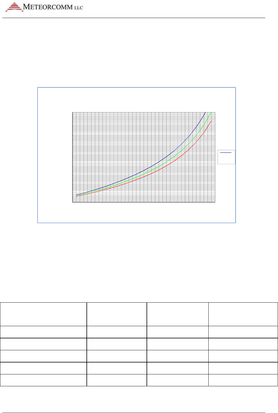
The height of the antenna should be optimized as a function of the
distance between the Remote Station and the Master Station. A plot of
optimum antenna height versus range is shown in Figure 3.3.
Figure 9: Remote station antenna height for meteor burst
The antenna cable length must be kept as short as possible to minimize
line losses. Try to maintain a line loss between the antenna and the
MCC-545C to less than 2 dB.
A table of cable loss (at 50 MHz) for various types of co-ax cables is
given in Table 3.1 for reference.
Table 5: CO-AX cable loss (50 MHz)
Cable Type Loss/100 feet
(dB)
Diameter
(Inches)
Weight/100 feet
(lbs.)
RG 223, RG 58
3.0
.211
3.4
RG 214, RG 8
1.8
.425
12.6
RG 17
1.2
.870
20.1
LDF4A-50 1/2 inch heliax
.48
.500
15.0
LDF5A-50 7/8 inch heliax
.26
.875
33.0
0
5
10
15
20
25
30
35
40
45
50
55
60
65
70
75
80
85
90
95
100
100
150
200
250
300
350
400
450
500
550
600
650
700
750
800
850
900
950
1000
Antenna Height (ft)
RANGE (mi)
Best Antenna Height
4
0
M
h

545C Operations Manual
02/10/2012 Prerelease DCN 00001789-A
26 © 2012 Meteorcomm LLC. All Rights Reserved. Proprietary and Confidential. Do Not Distribute.
4.1.6 Human Exposure To Radio Frequency Electromagnetic Fields
For fixed applications, antenna gains and mounting techniques can vary
depending on the application. Antennas suitable for use with the MCC-
545C are listed in the MCC-545C RF Energy Exposure Guide. It includes
details on the human to antenna separation requirements for specific
fixed and mobile antennas with various gains.
Always disable the transmitter when working on the antenna and/or co-
ax cable.
4.2 Equipment Installation
The MCC-545C operates over a temperature range from -30°C to +60°C
and is housed in a stainless steel enclosure that can be used in a wide
range of applications.
4.2.1 Mobile Applications
Mobile applications can include vehicles, aircraft, vessels, and
locomotives. Each application may require a different type of antenna.
For example, a 3' base-loaded ¼-wave whip is generally a good solution
for vehicles. Low profile antennas, vertically polarized, are required for
locomotives. 10' ¼-wave whips are generally used for vessels; these
antennas should be designed for operation in maritime environments.
Refer to the MCC-545C RF Energy Exposure Guide for more antenna
information and means to limit RF exposure. MCC’s engineering services
department can be contacted for specific recommendations.
For vehicle installations, the MCC-545C may be mounted in any
convenient location (e.g., in the trunk, under the seat, or in the engine
compartment).
Refer to Appendix E for a list of example equipment components
required for an MCC-545C used in a typical mobile application.
545C Operations Manual
02/10/2012 Prerelease DCN 00001789-A
© 2012 Meteorcomm LLC. All Rights Reserved. Proprietary and Confidential. Do Not Distribute. 27
4.2.2 Data Collection Applications
The case of the MCC-545C itself is not waterproof, and a NEMA
waterproof enclosure is recommended for outdoor installations. To
ensure proper operation, shielded cable is recommended for all
connectors. Also, use adequate strain relief on all cables and a
weatherproof seal at the entry point of the enclosure.
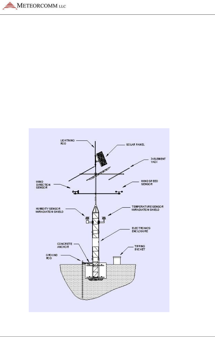
A typical Remote Station data collection installation is shown in Figure
3.4.
Refer to Appendix E for a list of example equipment components
required for an MCC-545C used in a typical data collection application.
Figure 10: Typical remote station with 3-element YAGI antenna
545C Operations Manual
02/10/2012 Prerelease DCN 00001789-A
28 © 2012 Meteorcomm LLC. All Rights Reserved. Proprietary and Confidential. Do Not Distribute.
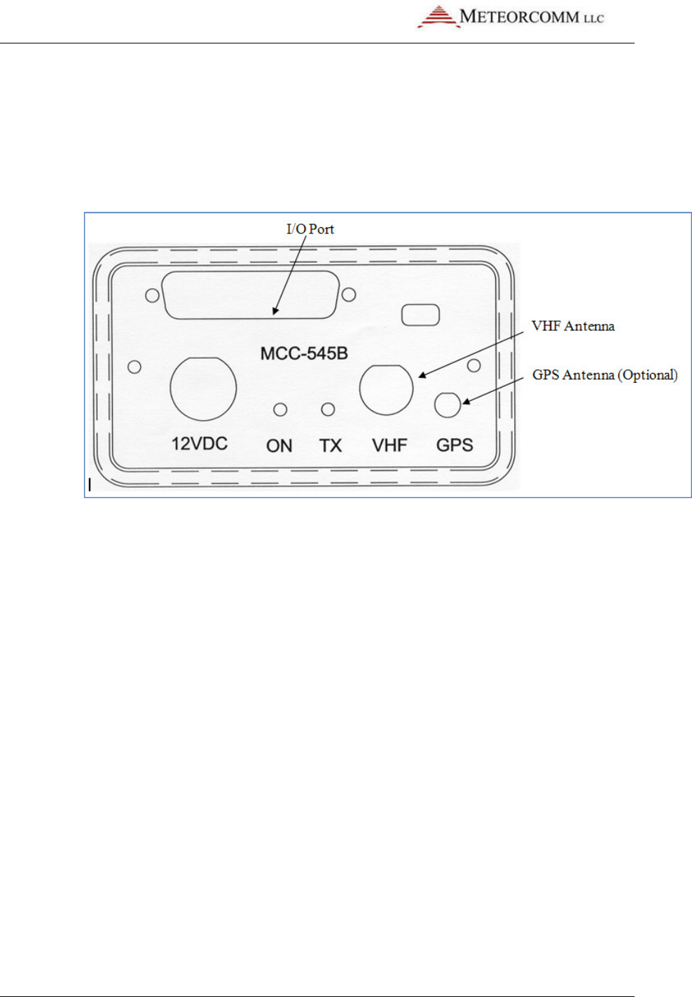
4.2.3 Cable Connections
There are a maximum of four cable connections to be made to the MCC-
545C, as shown in Figure 3.5. These connections are used for both
mobile and fixed site applications.
Figure 11: MCC-545C cable connections
DC Power
The MCC-545C requires a power source that can deliver up to 25 amps
of pulsed power (100 msec) out of a +12 VDC to +14VDC power source.
The 25 amp power demand will cause a voltage drop to occur at the
transmitter input, resulting in reduced transmit power, unless the
power cable to the source is sized appropriately. MCC recommends
using two #16 AWG wires for both the power and ground, with a cable
length that does not exceed 10 feet. If a longer cable is required use
#14 AWG. MCC provides a standard 6-foot power cable with lugs for
connecting to a 3/8" battery post.
The power connector pins are shown in Figure 3.6:

02/10/2012
© 2012 Meteorcomm LLC. All Right
Figure 12: MCC
-
The voltage at pins 1 and 4 should not drop by more than 2VDC during
transmission.
VHF Antenna
Connect the antenna cable to the BNC RF connector
used for cable lengths under 50 feet
214) for cable lengths up to 100 feet
cable length.
GPS Antenna (Opt
An external GPS antenna is required when the internal GPS receiver is
used.
Connect the GPS antenna cable to the SMA connector on the front
panel.
I/O Port
The 44 pin I/O connector on the front panel includes three RS
and one Sensor port
out these four ports as shown in Figure
545C Operations Manual
Prerelease
hts Reserved.
Proprietary and Confidential. Do Not Distribu
-
545C power connector pins
The voltage at pins 1 and 4 should not drop by more than 2VDC during
Connect the antenna cable to the BNC RF connector
. RG-
223 may be
used for cable lengths under 50 feet
.
Use a large diameter cable (RG
214) for cable lengths up to 100 feet
.
Refer to Section 3.1.5 for proper
GPS Antenna (Opt
ional)
An external GPS antenna is required when the internal GPS receiver is
Connect the GPS antenna cable to the SMA connector on the front
The 44 pin I/O connector on the front panel includes three RS
and one Sensor port
.
MCC provides a standard cable harness that breaks
out these four ports as shown in Figure
13:
545C Operations Manual
DCN 00001789-A
ibute.
29
The voltage at pins 1 and 4 should not drop by more than 2VDC during
223 may be
Use a large diameter cable (RG
-
Refer to Section 3.1.5 for proper
An external GPS antenna is required when the internal GPS receiver is
Connect the GPS antenna cable to the SMA connector on the front
The 44 pin I/O connector on the front panel includes three RS
-232 ports
MCC provides a standard cable harness that breaks
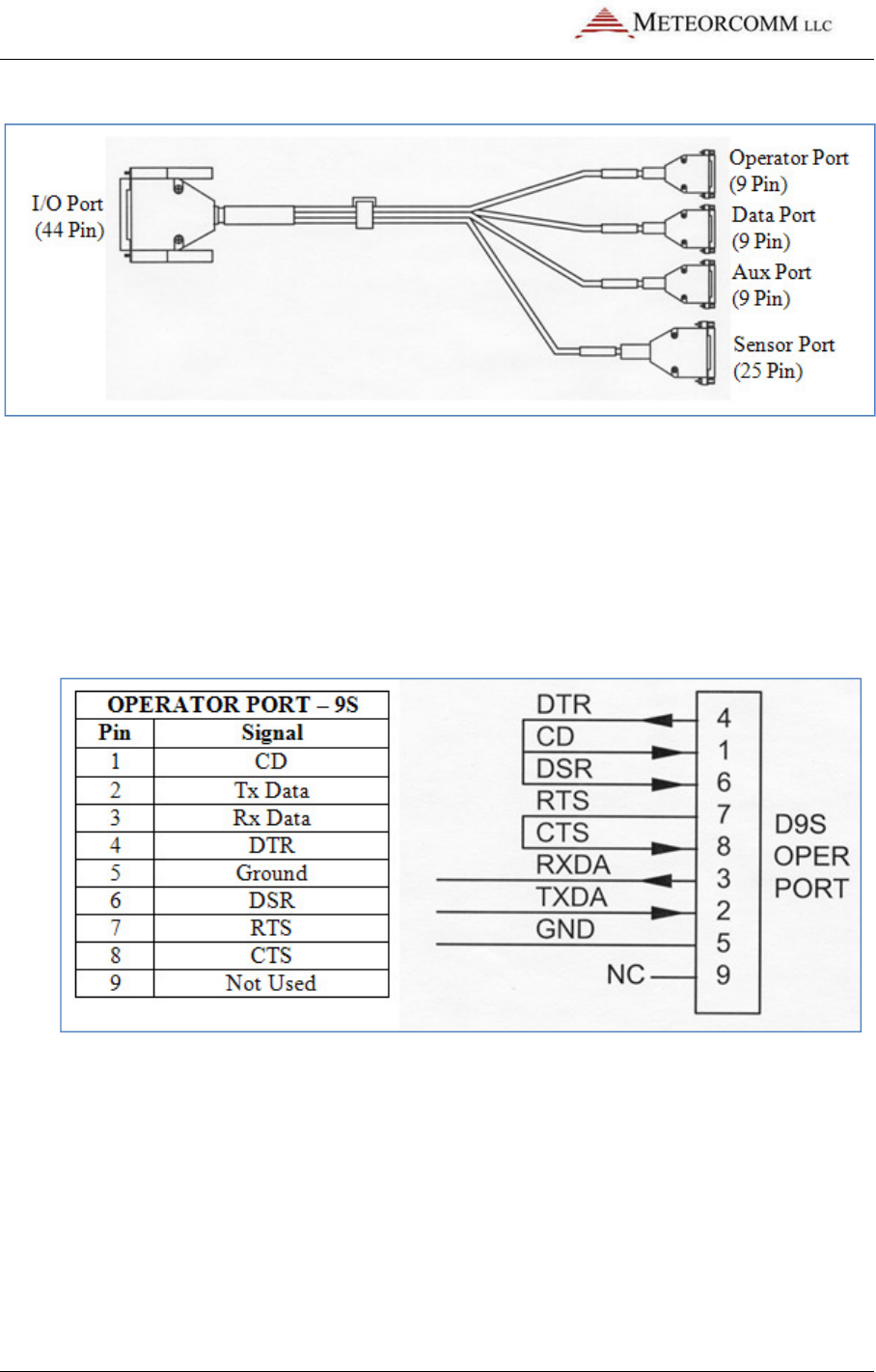
545C Operations Manual
02/10/2012 Prerelease DCN 00001789-A
30 © 2012 Meteorcomm LLC. All Rights Reserved. Proprietary and Confidential. Do Not Distribute.
Figure 13: MCC-545C I/O port cable
Operator Port
The Operator Port is normally connected to a local operator terminal.
Use a standard RS-232 cable with a 9-pin male D connector. Normally,
only 3 wires (pins 2, 3 and 5) are required when connecting to the
operator port. The port is wired to support handshaking where required
such as when using a modem.
Data Port
The Data Port may be used for connecting to a data logger, GPS
receiver or other serial input device. Use a standard RS-232 cable with a
9-pin male D connector. Refer to Section 4.5 for more information on
interfacing to data loggers or other serial input devices.
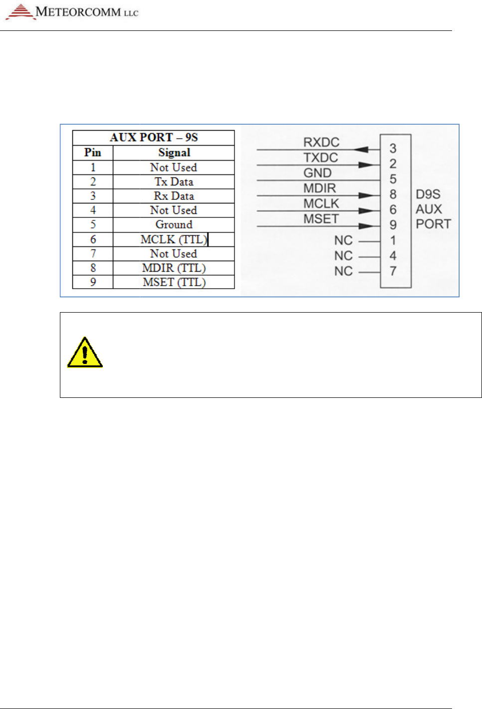
02/10/2012
© 2012 Meteorcomm LLC. All Right
Auxiliary Port (AUX)
The Auxiliary Port may be connected to any serial input device
standard RS-
232 cable with a 9
used for interfacing to MCC test equipment (pins 6, 8, and 9).
Important
and 9) whose signals do not conform to the RS
are for MCC test purposes. These pins will NOT interfere with a
normal 3
Sensor Port
The Sensor port is used as a gener
Data Acquisition (SCADA) interface requiring limited I/O in lieu of a full
data logging capability
connector for access to the various functions
cable may be
routed to a terminal block for interfacing to the various
sensors and other external devices.
545C Operations Manual
Prerelease
hts Reserved.
Proprietary and Confidential. Do Not Distribu
The Auxiliary Port may be connected to any serial input device
232 cable with a 9
-pin male D connector.
This port is also
used for interfacing to MCC test equipment (pins 6, 8, and 9).
Important
: The AUX port connector has t
hree extra pins (pins 6, 8,
and 9) whose signals do not conform to the RS
-
232 standard. These
are for MCC test purposes. These pins will NOT interfere with a
normal 3
-wire RS-
232 connector (pins 2, 3, and 5).
The Sensor port is used as a gener
al purpose Supervisory Control and
Data Acquisition (SCADA) interface requiring limited I/O in lieu of a full
data logging capability
. Use a mating cable with a 25-
pin male D
connector for access to the various functions
.
For convenience, this
routed to a terminal block for interfacing to the various
sensors and other external devices.
545C Operations Manual
DCN 00001789-A
ibute.
31
The Auxiliary Port may be connected to any serial input device
. Use a
This port is also
used for interfacing to MCC test equipment (pins 6, 8, and 9).
hree extra pins (pins 6, 8,
232 standard. These
are for MCC test purposes. These pins will NOT interfere with a
232 connector (pins 2, 3, and 5).
al purpose Supervisory Control and
Data Acquisition (SCADA) interface requiring limited I/O in lieu of a full
pin male D
For convenience, this
routed to a terminal block for interfacing to the various
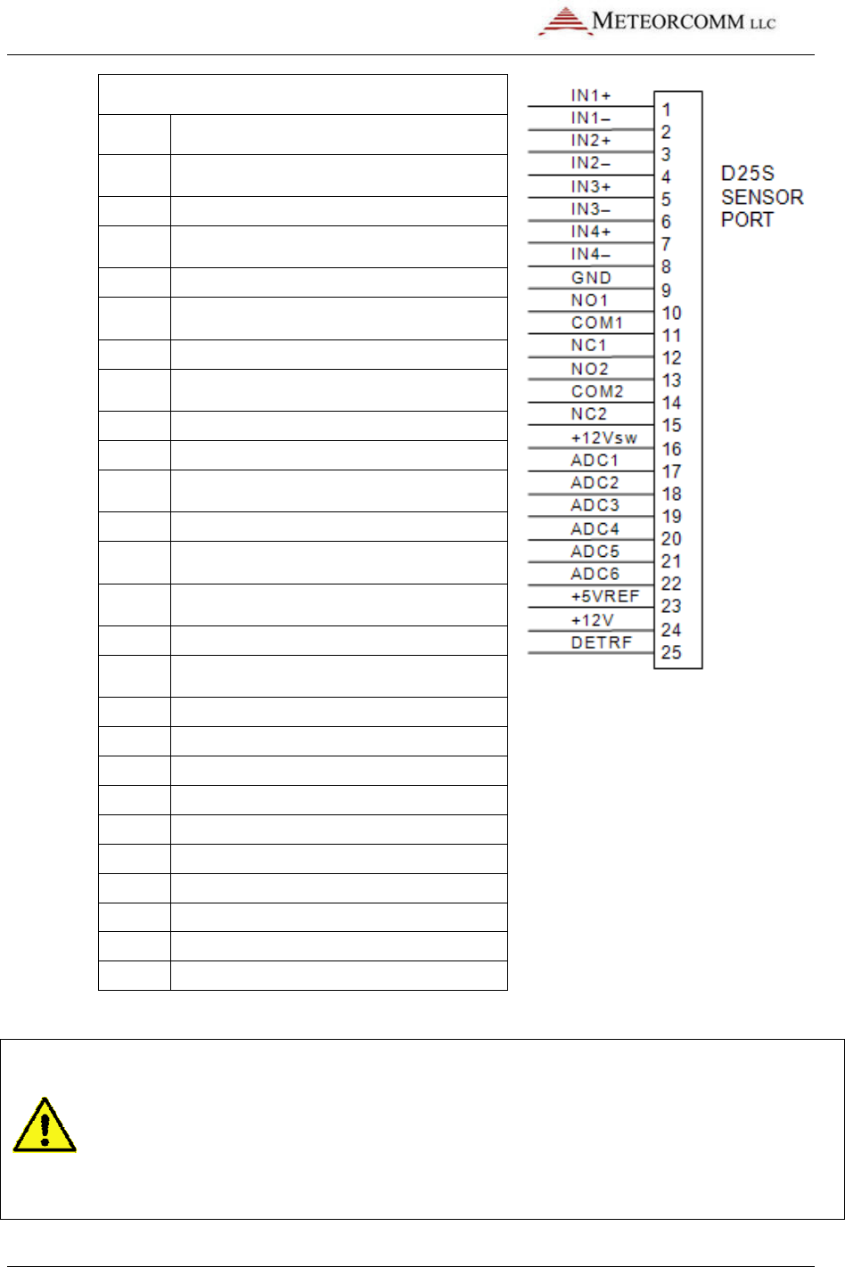
545C Operations Manual
02/10/2012
32
© 2012 Meteorcomm LLC.
SENSOR PORT
Pin Signal
1
Optocoupled input #1 positive
( 500 ohm resistor)
2
Optocoupled input #1 return
3
Optocoupled input #2 positive
( 500 ohm
resistor)
4
Optocoupled input #2 return
5
Optocoupled input #3 positive
( 500 ohm resistor)
6
Optocoupled input #3 return
7
Optocoupled input #4 positive
( 500 ohm resistor)
8
Optocoupled input #4 return
9
Ground
10
Relay Output #1 Normally Open
(2 Amp rating)
11
Relay Output #1 Common
12
Relay Output #1 Normally Closed
(2 Amp rating)
13
Relay Output #2 Normally Open
(2 Amp rating)
14
Relay Output #2 Common
15
Relay Output #2 Normally Closed
(2 Amp
rating)
16
Switched +12V (battery)
17
Analog Input #1 ( 0 to 5 V)
18
Analog Input #2 ( 0 to 5 V)
19
Analog Input #3 ( 0 to 5 V)
20
Analog Input #4 ( 0 to 5 V)
21
Analog Input #5 ( 0 to 5 V)
22
Analog Input #6 ( 0 to 5 V)
23
+5V Ref (10mA for sensor excitation)
24
+12V (0.5A maximum)
25
Detected RF Test Point
Note: In -
03 series or later radios, the sensor connector pin #16 has been
changed from ground to a switched +12 volt
volt can be used to drive sensors. The total current load on the +12 volt and
switched +12 volt must not exceed 500mA. Use EVENT programming (Section
4.6) to control the +12 volt switched output.
Prerelease
DCN
.
All Rights Reserved. Proprietary and Confidential. Do
Optocoupled input #1 positive
( 500 ohm resistor)
Optocoupled input #1 return
Optocoupled input #2 positive
resistor)
Optocoupled input #2 return
Optocoupled input #3 positive
( 500 ohm resistor)
Optocoupled input #3 return
Optocoupled input #4 positive
( 500 ohm resistor)
Optocoupled input #4 return
Relay Output #1 Normally Open
(2 Amp rating)
Relay Output #1 Common
Relay Output #1 Normally Closed
(2 Amp rating)
Relay Output #2 Normally Open
(2 Amp rating)
Relay Output #2 Common
Relay Output #2 Normally Closed
rating)
Switched +12V (battery)
Analog Input #1 ( 0 to 5 V)
±0.5%
Analog Input #2 ( 0 to 5 V)
±0.5%
Analog Input #3 ( 0 to 5 V)
±0.5%
Analog Input #4 ( 0 to 5 V)
±0.5%
Analog Input #5 ( 0 to 5 V)
±0.5%
Analog Input #6 ( 0 to 5 V)
±0.5%
+5V Ref (10mA for sensor excitation)
+12V (0.5A maximum)
Detected RF Test Point
03 series or later radios, the sensor connector pin #16 has been
changed from ground to a switched +12 volt
(battery). This switched +12
volt can be used to drive sensors. The total current load on the +12 volt and
switched +12 volt must not exceed 500mA. Use EVENT programming (Section
4.6) to control the +12 volt switched output.
DCN
00001789-A
Do Not Distribute.
03 series or later radios, the sensor connector pin #16 has been
(battery). This switched +12
volt can be used to drive sensors. The total current load on the +12 volt and
switched +12 volt must not exceed 500mA. Use EVENT programming (Section
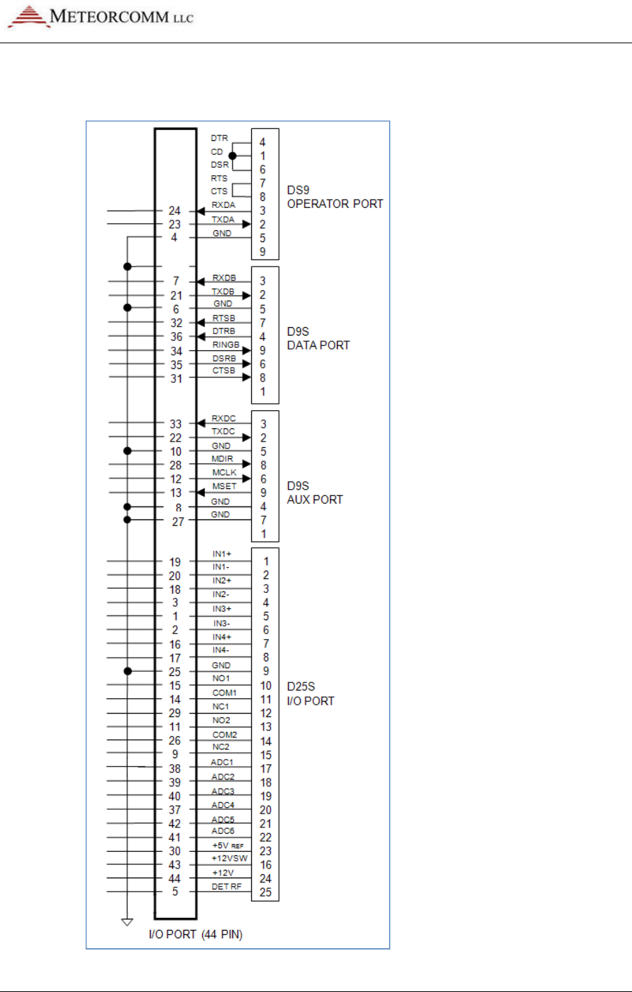
545C Operations Manual
02/10/2012 Prerelease DCN 00001789-A
© 2012 Meteorcomm LLC. All Rights Reserved. Proprietary and Confidential. Do Not Distribute. 33
For reference, the pin-outs of the 44 pin I/O connector are shown
below:
545C Operations Manual
02/10/2012
34
© 2012 Meteorcomm LLC.
4.3 Power-
Up Sequence
Important:
Before applying power to the MCC
between the MCC-
545C and the external equipment (power, antenna,
operator terminal, and data logger). Refer to Section
instructions.
Caution
:
3.3 have been completed.
4.3.1
Operator Terminal
Connect a laptop or an operator terminal, with
the Operator Port
.
emulation program designed for interfacing with MCC products
operator terminal must be programmed with the same configuration
parameters as the Operator Port.
The Operator Port of the MCC
factory default configuration at the time of shipment:
Baud rate
9600
Parity
Data bits
8
Protocol
Stop bit
1
Flow control
4.3.2
Power Connection
Power up the MCC
-
Note:
When the unit
review Section 3.2.3.1 for proper cabling to the power source. The voltage
drop at the input connector during transmission should be less than 2 VDC
for proper operation of the unit. Verify this during the
Procedure in Section 3.4.
Prerelease
DCN
.
All Rights Reserved. Proprietary and Confidential. Do
Up Sequence
Before applying power to the MCC
-
545C, check all connections
545C and the external equipment (power, antenna,
operator terminal, and data logger). Refer to Section
3.2.3 for cabling
:
Disconnect the antenna cable until all steps in Section
3.3 have been completed.
Operator Terminal
Connect a laptop or an operator terminal, with
XTermW
installed, to
.
XTermW is an MCC windows-
based terminal
emulation program designed for interfacing with MCC products
operator terminal must be programmed with the same configuration
parameters as the Operator Port.
The Operator Port of the MCC
-
545C is programmed with the f
factory default configuration at the time of shipment:
Parity
no
Protocol
ASCII
Flow control
none
Power Connection
-
545C by applying +12VDC to the power connector.
When the unit
transmits, it will draw up to 20 amps; therefore,
review Section 3.2.3.1 for proper cabling to the power source. The voltage
drop at the input connector during transmission should be less than 2 VDC
for proper operation of the unit. Verify this during the
Operational Test
Procedure in Section 3.4.
DCN
00001789-A
Do Not Distribute.
545C, check all connections
545C and the external equipment (power, antenna,
3.2.3 for cabling
Disconnect the antenna cable until all steps in Section
installed, to
based terminal
emulation program designed for interfacing with MCC products
. The
operator terminal must be programmed with the same configuration
545C is programmed with the f
ollowing
545C by applying +12VDC to the power connector.
transmits, it will draw up to 20 amps; therefore,
review Section 3.2.3.1 for proper cabling to the power source. The voltage
drop at the input connector during transmission should be less than 2 VDC
Operational Test

545C Operations Manual
02/10/2012 Prerelease DCN 00001789-A
© 2012 Meteorcomm LLC. All Rights Reserved. Proprietary and Confidential. Do Not Distribute. 35
When power applied is initially applied to the MCC-545C, or after a
software boot or hardware reset, the following message will be
displayed:
545C PACKET DATA RADIO
(c) Copyright 2005 Meteor Communications Corp.
All Rights Reserved
S/W Part Number* P1079-00-00 Version* 6.87 09/29/05
* Part Number, Version Number, and date vary according to a particular
radio’s firmware.
At this time all configuration data is loaded from Program Memory into
RAM. This data will remain in RAM and on all subsequent power-cycle
sequences the following message will be displayed:
01/23/04 16:54:10 POWER SHUTDOWN/FAIL OCCURRED.
02/02/04 12:54:44 POWER HAS BEEN RESTORED... RESUMING OPERATION.
+
This is the type of message that should be displayed when you first
apply power to the unit during a field installation, and for each
subsequent power cycle of the radio.
If the greeting message is not displayed, then the RAM contents may
have been lost under one of the conditions described in Section 2.4 and
the proper script file must be re-entered into the MCC-545C using
XTermW. (Refer to Sections 3.3.3.5 and 4.2.7 and Appendix C for more
information on using script files.)
4.3.3 Initialization Procedures
The following initialization procedures should now be performed in the
order they are given below.
Verify Device Type
The MCC-545C must be programmed to operate as a particular device
type, such as Remote Station, Repeater, or Base, depending on your
network configuration. The device type is normally set at the factory
prior to shipment to ensure proper integration with your network.

545C Operations Manual
02/10/2012
36
© 2012 Meteorcomm LLC.
Use the following command to display what device type the unit is
configured as:
DEVICE [ENTER]
Always check with your System Administrator to determine which device
type
your unit should be configured as.
For example, if the device should be a Remote Station and it is not
currently configured properly, you can change the device type, as
follows:
DEVICE,REMOTE [ENTER]
SAVE [ENTER]
Caution:
Do not change the device type u
Administrator. Changing the device type can make your unit cease operating
and can impact communications throughout the entire network.
Verify ID Number
Every MCC unit is programmed at the factory with a 16
display the unit ID number on the operator terminal, enter:
ID [ENTER]
Contact your System Administrator to make sure this ID is registered in
the network configuration database
may have to be changed on
locked.
Caution:
ID changes must be coordinated with both MCC and your System
Administrator. Failure to do so may result in data or messages being
misrouted or lost. Refer to Section 4.1.4.1 for more information on unit ID
settings.
Verify Frequency
The MCC-
545C is programmed at the factory with the authorized
frequencies to be used in your network
Parameter memory and cannot be changed
frequency is configured by enter
Prerelease
DCN
.
All Rights Reserved. Proprietary and Confidential. Do
Use the following command to display what device type the unit is
Always check with your System Administrator to determine which device
your unit should be configured as.
For example, if the device should be a Remote Station and it is not
currently configured properly, you can change the device type, as
DEVICE,REMOTE [ENTER]
Do not change the device type u
nless told to do so by your System
Administrator. Changing the device type can make your unit cease operating
and can impact communications throughout the entire network.
Every MCC unit is programmed at the factory with a 16
-
bit unit ID
display the unit ID number on the operator terminal, enter:
Contact your System Administrator to make sure this ID is registered in
the network configuration database
.
Under some circumstances the ID
may have to be changed on
-site. This can o
nly be done if the ID is not
ID changes must be coordinated with both MCC and your System
Administrator. Failure to do so may result in data or messages being
misrouted or lost. Refer to Section 4.1.4.1 for more information on unit ID
545C is programmed at the factory with the authorized
frequencies to be used in your network
.
These frequencies are stored in
Parameter memory and cannot be changed
.
Verify that the correct
frequency is configured by enter
ing the command:
DCN
00001789-A
Do Not Distribute.
Use the following command to display what device type the unit is
Always check with your System Administrator to determine which device
For example, if the device should be a Remote Station and it is not
currently configured properly, you can change the device type, as
nless told to do so by your System
Administrator. Changing the device type can make your unit cease operating
and can impact communications throughout the entire network.
bit unit ID
. To
Contact your System Administrator to make sure this ID is registered in
Under some circumstances the ID
nly be done if the ID is not
ID changes must be coordinated with both MCC and your System
Administrator. Failure to do so may result in data or messages being
misrouted or lost. Refer to Section 4.1.4.1 for more information on unit ID
545C is programmed at the factory with the authorized
These frequencies are stored in
Verify that the correct

02/10/2012
© 2012 Meteorcomm LLC. All Right
FREQUENCIES [ENTER]
or
FREQ [ENTER]
This shows you the active or “primary” TX and RX frequency pair, plus
up to 9 additional frequency pairs for channels that may be
programmed at the factory.
For example, the following
+freq 05/18/04 08:53:50 Primary TX 044.58 MHz RX 044.58 MHz
Frequency Table
Channel
>00*
01
02
03
04
05
06
07
08
09
Caution:
Do not change the frequency pair unless told to do so by your
System Administrator. Changing the frequency pair can
communicating with the network.
Once the frequencies are verified, confirm that the synthesizer is “ON”
and locked by entering the following command:
SYNTHESIZER [ENTER]
or
SYNTH [ENTER]
The unit responds with:
SYNTH
,ON,LOCKED (or UNLOCKED)
If the synthesizer returns an unlocked response, ensure that the proper
frequency pair is selected.
545C Operations Manual
Prerelease
hts Reserved.
Proprietary and Confidential. Do Not Distribu
FREQUENCIES [ENTER]
FREQ [ENTER]
for short cut
This shows you the active or “primary” TX and RX frequency pair, plus
up to 9 additional frequency pairs for channels that may be
programmed at the factory.
For example, the following
table could be displayed:
+freq 05/18/04 08:53:50 Primary TX 044.58 MHz RX 044.58 MHz
Frequency Table
TX RX
044.58 MHz
044.58 MHz
045.90 MHz
044.20 MHz
000.00 MHz
000.00 MHz
000.00 MHz
000.00 MHz
000.00 MHz
000.00 MHz
000.00 MHz
000.00 MHz
000.00 MHz
000.00 MHz
000.00 MHz
000.00 MHz
000.00 MHz
000.00 MHz
000.00 MHz
000.00 MHz
Do not change the frequency pair unless told to do so by your
System Administrator. Changing the frequency pair can
make your unit stop
communicating with the network.
Once the frequencies are verified, confirm that the synthesizer is “ON”
and locked by entering the following command:
SYNTHESIZER [ENTER]
SYNTH [ENTER]
for short cut
The unit responds with:
,ON,LOCKED (or UNLOCKED)
If the synthesizer returns an unlocked response, ensure that the proper
frequency pair is selected.
545C Operations Manual
DCN 00001789-A
ibute.
37
This shows you the active or “primary” TX and RX frequency pair, plus
up to 9 additional frequency pairs for channels that may be
+freq 05/18/04 08:53:50 Primary TX 044.58 MHz RX 044.58 MHz
044.58 MHz
044.20 MHz
000.00 MHz
000.00 MHz
000.00 MHz
000.00 MHz
000.00 MHz
000.00 MHz
000.00 MHz
000.00 MHz
Do not change the frequency pair unless told to do so by your
make your unit stop
Once the frequencies are verified, confirm that the synthesizer is “ON”
If the synthesizer returns an unlocked response, ensure that the proper

545C Operations Manual
02/10/2012
38
© 2012 Meteorcomm LLC.
Note: The MCC-
545C will not transmit if the synthesizer is not locked.
Select Site Name
A descriptive name may be given to the s
being installed.
The selected site name must be coordinated with your
System Administrator
SITE NAME, nnnnnn [ENTER]
where: nnnnnn = maximum of 32 alpha
Caution: Please
double
spacing. Data from a site with an incorrect site name will be mishandled or
misrouted by the Host. An incorrect site name can result in significant effort
to recover misrouted data.
Enter Script Files
The appropriate Script File is usually programmed into the MCC
the factory prior to shipment
not been entered, a new file can be loaded from your operator terminal
using XTermW
software
the MCC-
545C to operate as either a Base, Repeater, or Remote Station
Other Script Files define any application programs that are performed
by the station. For example, the application for a Remote Station may
be as a
mobile unit reporting position data or as a fixed site reporting
sensor data.
The procedure for loading the Script File is described below:
1.
Install the MCC
Script File on it into your operator terminal, and load t
File into your
2. Start
XTermW
and COM port (typically COM1, 9600 baud)
are defaults.
3. Type
factory,default,init
into the MCC
Prerelease
DCN
.
All Rights Reserved. Proprietary and Confidential. Do
545C will not transmit if the synthesizer is not locked.
A descriptive name may be given to the s
ite where the MCC-
545C is
The selected site name must be coordinated with your
System Administrator
.
To enter a site name use the following command:
SITE NAME, nnnnnn [ENTER]
where: nnnnnn = maximum of 32 alpha
-characters
double
-
check the site name entry for correct spelling and
spacing. Data from a site with an incorrect site name will be mishandled or
misrouted by the Host. An incorrect site name can result in significant effort
to recover misrouted data.
The appropriate Script File is usually programmed into the MCC
the factory prior to shipment
.
If the appropriate Script File has already
not been entered, a new file can be loaded from your operator terminal
software
. There is on
e Script File that uniquely programs
545C to operate as either a Base, Repeater, or Remote Station
Other Script Files define any application programs that are performed
by the station. For example, the application for a Remote Station may
mobile unit reporting position data or as a fixed site reporting
The procedure for loading the Script File is described below:
Install the MCC
-545C Meteorcomm
CD (or diskette), with the
Script File on it into your operator terminal, and load t
File into your
XTermW subdirectory.
XTermW
and open a connection at the correct baud rate
and COM port (typically COM1, 9600 baud)
.
All other parameters
are defaults.
factory,default,init
to load the default parameters
into the MCC
-545C.
DCN
00001789-A
Do Not Distribute.
545C will not transmit if the synthesizer is not locked.
545C is
The selected site name must be coordinated with your
To enter a site name use the following command:
check the site name entry for correct spelling and
spacing. Data from a site with an incorrect site name will be mishandled or
misrouted by the Host. An incorrect site name can result in significant effort
The appropriate Script File is usually programmed into the MCC
-545C at
If the appropriate Script File has already
not been entered, a new file can be loaded from your operator terminal
e Script File that uniquely programs
545C to operate as either a Base, Repeater, or Remote Station
.
Other Script Files define any application programs that are performed
by the station. For example, the application for a Remote Station may
mobile unit reporting position data or as a fixed site reporting
CD (or diskette), with the
Script File on it into your operator terminal, and load t
he Script
and open a connection at the correct baud rate
All other parameters
to load the default parameters

02/10/2012
© 2012 Meteorcomm LLC. All Right
4.
From the
Script.
5.
Select the appropriate Script File in the
Double-
click the file name to start execution.
The commands in the Script File are executed one at a time until the
end of
the file is reached
review the command responses
COMMAND, BAD PARAMETER, or a similar message, the Script File may
have an error in it
MCC or your System Administrator for a replacement.
You may verify that the correct configuration file has been loaded by
entering the three commands:
THIS COMPLETES THE INTIALIZATION PROCEDURE
4.4
Operational Test Procedure
Note:
Be sure to connect the antenna if it was disconnected per the
CAUTION note of Section 3.3.
4.4.1 RF Test
A very thorough RF test can be made by entering the command TEST
[ENTER].
TEST causes the processor to turn the transmitter ON and
measures the
forward and reverse RF power that is being transmitted
also measures the battery voltage under load and the antenna noise
voltage.
545C Operations Manual
Prerelease
hts Reserved.
Proprietary and Confidential. Do Not Distribu
From the
Scripts pull-down menu in XTermW
, choose Execute
Select the appropriate Script File in the
XTermW
subdirectory
click the file name to start execution.
The commands in the Script File are executed one at a time until the
the file is reached
.
Press the “up arrow” key to scroll up and
review the command responses
.
If any commands result in BAD
COMMAND, BAD PARAMETER, or a similar message, the Script File may
have an error in it
.
If so, the script file needs to be corrected
MCC or your System Administrator for a replacement.
You may verify that the correct configuration file has been loaded by
entering the three commands:
ASSIGN, SNP, and CONFIG
.
THIS COMPLETES THE INTIALIZATION PROCEDURE
Operational Test Procedure
Be sure to connect the antenna if it was disconnected per the
CAUTION note of Section 3.3.
A very thorough RF test can be made by entering the command TEST
TEST causes the processor to turn the transmitter ON and
forward and reverse RF power that is being transmitted
also measures the battery voltage under load and the antenna noise
545C Operations Manual
DCN 00001789-A
ibute.
39
, choose Execute
subdirectory
.
The commands in the Script File are executed one at a time until the
Press the “up arrow” key to scroll up and
If any commands result in BAD
COMMAND, BAD PARAMETER, or a similar message, the Script File may
If so, the script file needs to be corrected
. Contact
You may verify that the correct configuration file has been loaded by
.
THIS COMPLETES THE INTIALIZATION PROCEDURE
Be sure to connect the antenna if it was disconnected per the
A very thorough RF test can be made by entering the command TEST
TEST causes the processor to turn the transmitter ON and
forward and reverse RF power that is being transmitted
. It
also measures the battery voltage under load and the antenna noise

545C Operations Manual
02/10/2012
40
© 2012 Meteorcomm LLC.
The following response will be displayed on the operator terminal:
syncs xmits acks pwr
xxxx yyyy zzzz aaaa bbbb ccc ddd eee
where: xxxx =
# of sync patterns received from the master station.
yyyy =
# of transmissions made by the MCC
zzzz =
# of acknowledgements received from the Master
aaaa =
Forward power in watts
bbbb =
Reflected power in watts
ccc =
Battery voltage under load (while transmitting)
greater than 10.6
ddd =
Received signal strength in
noise level at the antenna and should read about
eee =
Number of times the radio has rebooted.
Note:
The forward RF power should be at least 80 watts if the battery
voltage
is normal. If it is lower than 80 watts check for proper cabling to
the power source. (See Section 3.2.2.1.)
If the reverse RF power is greater than 5 watts check the antenna and
coaxial cabling for proper installation.
If both the forward and reverse pow
automatically shutting down due to an antenna VSWR greater than 3:1.
Check the antenna and coaxial cabling for proper installation.
If the DET RF is greater than
will still perfo
rm properly but the latency time of the link will be increased.
Refer to Section 3.1 for reducing site noise conditions.
An overall figure of merit for the link performance is the XMIT to ACK ratio.
If this ratio is 3:1 or lower, the overall performance wi
This completes the initialization and power
The unit is now ready for operation.
Refer to Chapter 4 for detailed operating instructions.
Prerelease
DCN
.
All Rights Reserved. Proprietary and Confidential. Do
The following response will be displayed on the operator terminal:
syncs xmits acks pwr
-fwd pwr-rev v-bat det-
rf resets
xxxx yyyy zzzz aaaa bbbb ccc ddd eee
# of sync patterns received from the master station.
# of transmissions made by the MCC
-545C.
# of acknowledgements received from the Master
Station.
Forward power in watts
.
This should be greater than 80 watts.
Reflected power in watts
.
This should be less than 5 watts.
Battery voltage under load (while transmitting)
.
This should be
greater than 10.6
V
DC
.
Received signal strength in
dBm.
This will normally be the
noise level at the antenna and should read about
–
120.
Number of times the radio has rebooted.
The forward RF power should be at least 80 watts if the battery
is normal. If it is lower than 80 watts check for proper cabling to
the power source. (See Section 3.2.2.1.)
If the reverse RF power is greater than 5 watts check the antenna and
coaxial cabling for proper installation.
If both the forward and reverse pow
er are low, the transmitter may be
automatically shutting down due to an antenna VSWR greater than 3:1.
Check the antenna and coaxial cabling for proper installation.
If the DET RF is greater than
–115 dBm (for example, -
110 dBm), the unit
rm properly but the latency time of the link will be increased.
Refer to Section 3.1 for reducing site noise conditions.
An overall figure of merit for the link performance is the XMIT to ACK ratio.
If this ratio is 3:1 or lower, the overall performance wi
ll be very good.
This completes the initialization and power
-
up sequence of the MCC
The unit is now ready for operation.
Refer to Chapter 4 for detailed operating instructions.
DCN
00001789-A
Do Not Distribute.
The following response will be displayed on the operator terminal:
rf resets
xxxx yyyy zzzz aaaa bbbb ccc ddd eee
Station.
This should be greater than 80 watts.
This should be less than 5 watts.
This should be
This will normally be the
120.
The forward RF power should be at least 80 watts if the battery
is normal. If it is lower than 80 watts check for proper cabling to
If the reverse RF power is greater than 5 watts check the antenna and
er are low, the transmitter may be
automatically shutting down due to an antenna VSWR greater than 3:1.
110 dBm), the unit
rm properly but the latency time of the link will be increased.
An overall figure of merit for the link performance is the XMIT to ACK ratio.
ll be very good.
up sequence of the MCC
-545C.

545C Operations Manual
02/10/2012 Prerelease DCN 00001789-A
© 2012 Meteorcomm LLC. All Rights Reserved. Proprietary and Confidential. Do Not Distribute. 41
5. OPERATIONS
This chapter covers the basic operating procedures for the MCC-545C as
it is used in the FleetTrak™ network. The MCC-545C is programmed
through the use of Script Files that contain the specific system
parameters for operating in various modes. A script file is loaded into
the MCC-545C at the MCC facilities prior to shipment. Script files may
also be loaded and/or modified at the customer’s site. (Refer to Section
4.2.7 and Appendix C for more information on Script Files.)
The last section of this chapter provides a summary of all MCC-545C
commands; printouts from frequently-used commands are included in
Appendix A.
It is assumed at this point that the appropriate script file has already
been loaded into the unit, as part of the installation procedures
outlined in Section 3.3, and that the unit is configured properly and
operational within its network. This chapter describes the various
commands that are available to the operator for modifying the station
configuration parameters to accommodate specific applications, sending
and receiving messages, and interfacing to peripheral devices for
position reporting and data collection.
5.1 Getting Started
5.1.1 XTermW Terminal Emulator
XTermW is a windows-based terminal emulation program supplied by
MCC. It is designed for interfacing with a wide variety of MCC products.
All commands, script files, etc., can be entered into the MCC-545C
using XTermW. The last section in this chapter contains a list of all valid
MCC-545C commands.
XTermW can also be used to create log files of MCC-545C operations.
Refer to the XTermW documentation supplied with the program.
Whether using XTermW, another terminal emulator, or a hardware
terminal, you must program the operator terminal to use the same

545C Operations Manual
02/10/2012 Prerelease DCN 00001789-A
42 © 2012 Meteorcomm LLC. All Rights Reserved. Proprietary and Confidential. Do Not Distribute.
configuration parameters as the MCC-545C Operator Port. The Operator
Port of the MCC-545C has the following factory default configuration:
Baud rate
9600
Data bits
8
Stop bit
1
Parity
no
Protocol
ASCII
Flow control
none
5.1.2 HELP Command
Entering HELP [ENTER] displays all of the commands used in the
operation and maintenance of the MCC-545C. To obtain descriptive
information about a particular command and how it is used by the MCC-
545C, enter the command type. For example: HELP, ASSIGN [ENTER].
Refer to the last section of this chapter for a complete list of MCC-545C
commands.
5.1.3 Role-Based Operations
The role that the MCC-545C plays in a communications network
determines how it should be configured. There are three basic roles
that an MCC-545C can be used in, depending on the network type:
• LOS Network consisting of Base and Repeater Stations, and
Remote/Mobile units; Base Stations do not communicate with each
other in this type of network. This is a typical FleetTrak™ network.
• LOS Network consisting of one or more Master Stations and Remote
Stations (either fixed position or mobile units); Master Stations can
communicate with each other in this type of network. This is a
typical DataNet network.
• Meteor Burst network consisting of a single Master Station
communicating with Remote Stations in fixed positions; Remote
Stations do not communicate with each other in this type of
network. This is a typical Meteor Burst network.

545C Operations Manual
02/10/2012 Prerelease DCN 00001789-A
© 2012 Meteorcomm LLC. All Rights Reserved. Proprietary and Confidential. Do Not Distribute. 43
Table 4.1 shows the roles for which an MCC-545C can be configured; this is just an overview of the general commands
needed for each role. The MCC-545C is not normally used in a Meteor Burst-only type of network.
Appendix F contains a description of the interoperability of all three types of MCC networks.
Table 6: Role-based operations
LOS Network
Base and Repeater Stations
Remote/Mobile units
LOS Network
Multiple Master Stations
Remote Stations (fixed or mobile)
Meteor Burst Network
Single Master Station
Remote Stations (fixed)
ROLE,LOS ROLE,LOS ROLE,TRANSPOND
DEVICE,BASE
DEVICE,REPEATER,id (which Base or
Repeater to report to)
DEVICE,REMOTE
DEVICE,MASTER
DEVICE,REMOTE
DEVICE,REMOTE
For Base/Repeaters:
ID,master id
For Remotes:
ID,remote id, master
id,AUTO
For Masters:
ID,master id
For Remotes:
ID,remote id, master id
For Masters:
ID,master id
For Remotes (single Master):
ID,remote id, master id
For Remotes (multiple Masters):
ID,remote id,1,MULTI,INIT
P,t
(idle probe rate – typically t=20
seconds for Base and Repeaters; set
t=OFF for Remotes in an LOS network)
P,t
(idle probe rate
–
typically
t=
20
seconds for Base and Repeaters; set
t=OFF for Remotes in an LOS network)
P,OFF
(for Remotes)
BASE,low id,hi id (typically 2-230 –
used as a switch that turns the
Base/Repeater mode on)
BASE,OFF
(BASE command not used in a Meteor
Burst network)
CONNECT, master id1, master id2
(limits which Master(s) a Remote Station
can communicate with)
CONNECT, master id1, master id2
(limits which Master(s) a Remote Station
or Master Station can communicate with)
(CONNECT command not used in a Meteor
Burst network)
SNP,NDOWN,2,10 (Remotes switch to SNP,NDOWN,120,10
(Remotes switch to
(Single Master Station networks use

545C Operations Manual
02/10/2012 Prerelease DCN 00001789-A
44 © 2012 Meteorcomm LLC. All Rights Reserved. Proprietary and Confidential. Do Not Distribute.
LOS Network
Base and Repeater Stations
Remote/Mobile units
LOS Network
Multiple Master Stations
Remote Stations (fixed or mobile)
Meteor Burst Network
Single Master Station
Remote Stations (fixed)
another Base Station or Repeater after 2
minutes without communications or after
10 failed tries; if only one Base Station,
Remote goes into position (POS)
broadcast mode )
another
Master Station after 120 minutes
without communications or after 10
failed tries; if only one Base Station,
Remote goes into position (POS)
broadcast mode )
default SNP parameters)
POS,15 (sets up GPS; typically 15
seconds, or 120 seconds depending on
requirements)
CR10X
(displays data logger
configuration parameters; can be
changed as needed)
CR10X
(displays data logger
configuration parameters; can be
changed as needed)
ASSIGN,POS,2,GPS (sets up RS-232
port)
ASSIGN,DTA,1,type
(select data
logger type for DTA port)
ASSIGN,DTA,1,type
(select data
logger type for DTA port)

545C Operations Manual
02/10/2012 Prerelease DCN 00001789-A
© 2012 Meteorcomm LLC. All Rights Reserved. Proprietary and Confidential. Do Not Distribute. 45
5.1.4 Unit Identification and Factory Settings
Unit ID
Every MCC unit is programmed at the factory with a 16-bit unit ID. This
allows up to 65,536 unique ID numbers per network. Type the command ID
and press [ENTER] to display the unit ID number on the operator terminal.
In some cases this number will be “locked” and cannot be changed in the
field; you can type LOCK to determine if the ID is locked or not.
Under some circumstances the ID may have to be changed on-site. It can
only be done if the ID is not locked. In that event, this action must be
coordinated with both MCC and your System Administrator. Failure to do so
may result in data or messages being misrouted or lost. In addition, the
network topography and statistics will receive incorrect data that will
impair network performance.
To change the ID, enter the following command:
ID,nnnnn,mmmm{,aaaaa},INIT
where:nnnnnn = unit ID
mmmm = Master Station assignment
aaaaa = Master select mode: PREF, AUTO, MULTI, or FIXED
Obtain the proper Master Station assignment and select mode from your
System Administrator. The MCC-545C will save this ID and will use it
whenever the unit is powered up or reset.
Mode Description
PREF
Unit connects to the
mmmm
Master Station for the
NDOWN
period (set with
SNP command). After NDOWN period unit connects to the Master Station
that it has received the most syncs from. In this mode the unit can
communicate with only one Master at a time.
AUTO
Unit connects to the
mmmm
Master Station, if it is not successful it
switches to another Master Station. It will stay with that Master Station as
long as it can communicate with it. In this mode the unit can
communicate with only one Master at a time. This is the standard
mode for FleetTrak™ networks.

545C Operations Manual
02/10/2012
46
© 2012 Meteorcomm LLC.
Mode Description
FIXED
Connectivity will be fixed to the
unit can communicate with only one Master Station at a time
the
standard mode for networks with a single Master Station.
MULTI
In this mode the unit can connect to multiple Master Stations
standard mode for Meteor Burst networks with more than one Master
Station.
The format for this mode is:
ID,nnnnn,1,M
ULTI,INIT
You can also change just the mode for the ID by typing:
ID,aaaaa
Customer ID
The MCC-
545C may also be assigned a unique customer ID number that can
correspond to a customer
number, or other
identifier as needed.
Factory Default Parameters
When you type FACTORY,DEFAULT,INIT, the unit restores the factory
default parameters. Refer to Appendix B for more details regarding the
factory default parameters.
Note:
If the ID and the CONFIG are not
FACTORY,DEFAULT,INIT, the unit’s ID will remain the same, but the ID mode
will be set to be the fixed mode . The frequency synthesizer will get
unlocked (Both TX and RX frequencies will be set to 99.99 MHz.). In this
case, you need to
set your frequencies again, in addition to other
parameters, using the script file (refer to Section 4.2.7).
5.1.5
System Time and Date
The MCC-
545C has its own internal clock
its clock to the nearest second either with its ass
own internal GPS receiver (if available)
TIMESYNC,source
Prerelease
DCN
© 2012 Meteorcomm LLC.
All Rights Reserved. Proprietary and Confidential. Do Not Distribute.
Connectivity will be fixed to the
mmmm
Master Station
.
In this mode the
unit can communicate with only one Master Station at a time
standard mode for networks with a single Master Station.
In this mode the unit can connect to multiple Master Stations
standard mode for Meteor Burst networks with more than one Master
The format for this mode is:
ULTI,INIT
You can also change just the mode for the ID by typing:
545C may also be assigned a unique customer ID number that can
correspond to a customer
-
specific network or system ID, an asset tracking
identifier as needed.
When you type FACTORY,DEFAULT,INIT, the unit restores the factory
default parameters. Refer to Appendix B for more details regarding the
factory default parameters.
If the ID and the CONFIG are not
LOCKED before typing
FACTORY,DEFAULT,INIT, the unit’s ID will remain the same, but the ID mode
will be set to be the fixed mode . The frequency synthesizer will get
unlocked (Both TX and RX frequencies will be set to 99.99 MHz.). In this
set your frequencies again, in addition to other
parameters, using the script file (refer to Section 4.2.7).
System Time and Date
545C has its own internal clock
–
periodically it can synchronize
its clock to the nearest second either with its ass
igned Master Station or its
own internal GPS receiver (if available)
.
Enter the following command:
TIMESYNC,source
DCN
00001789-A
All Rights Reserved. Proprietary and Confidential. Do Not Distribute.
In this mode the
unit can communicate with only one Master Station at a time
. This is
standard mode for networks with a single Master Station.
In this mode the unit can connect to multiple Master Stations
.
This is the
standard mode for Meteor Burst networks with more than one Master
545C may also be assigned a unique customer ID number that can
specific network or system ID, an asset tracking
When you type FACTORY,DEFAULT,INIT, the unit restores the factory
default parameters. Refer to Appendix B for more details regarding the
FACTORY,DEFAULT,INIT, the unit’s ID will remain the same, but the ID mode
will be set to be the fixed mode . The frequency synthesizer will get
unlocked (Both TX and RX frequencies will be set to 99.99 MHz.). In this
set your frequencies again, in addition to other
periodically it can synchronize
igned Master Station or its
Enter the following command:

545C Operations Manual
02/10/2012 Prerelease DCN 00001789-A
© 2012 Meteorcomm LLC. All Rights Reserved. Proprietary and Confidential. Do Not Distribute. 47
where: source = ON (sync with Master Station)
= GPS (sync using internal GPS)
= OFF (uses internal clock only)
If required, the MCC-545C’s internal date and time can be initialized by
entering the following commands:
DATE, mm/dd/yy
TIME, hh:mm{:ss}
The Master Station receives the correct date and time from either its Host
or an RTCM broadcast. The Master Station then periodically broadcasts this
date and time information to all Remotes for synchronizing their internal
clocks.
The date and time of day maintained in the MCC-520B Master Station is
transmitted to all Remote Stations between the times of 00:10:00 and
00:50:00 of each day, time keeping all units in a network on the same time
reference. If the time of day received at a Remote Station differs by more
than two minutes from the internal Remote clock, the Remote will set its
clock to the received time of day.
To properly manage time, each Master Station and Remote Station must
know how its own time zone relates to UTC and the system time. This
relationship is established by relating its time zone to known reference
points. UTC is always referenced to GMT; however, system time can be
referenced to any desired time zone.
The time zone offset is defined with the following command:
TIME ZONE, UTC offset, local time offset
Always set “UTC offset” to 0; the “local time offset” should be set to the
Remote Station’s time zone offset (+/- TZ) from the Master Station time
zone.
5.1.6 System Memory
The MCC-545C is designed to operate unattended in a variety of
environments where power may be applied continuously or intermittently.
The goal is for the unit to continue to operate without loss of messages,
data, or configuration, even if power is randomly turned on and off.

545C Operations Manual
02/10/2012 Prerelease DCN 00001789-A
48 © 2012 Meteorcomm LLC. All Rights Reserved. Proprietary and Confidential. Do Not Distribute.
Therefore the software is designed to operate continuously, to save all
operational information when power is off, and to resume operation from
that point when power is restored.
To support this design, the MCC-545C has three types of memory:
1. Program Memory (PM)
2. Random Access Memory (RAM)
3. Configuration Parameter (CPM)
The PM is non-volatile flash memory that has been programmed with the
MCC-545C’s operational software. This software contains the initial values
of all operational parameters. The values are referred to as the “factory
defaults” because they are programmed into the MCC-545C operating
system software at the factory. The PM can only be modified by replacing
the operating system using the flash download. (Consult XTermW manual to
learn how to download a new flash into the PM.)
The RAM contains all the dynamic data for the MCC-545C. All data logger
data, positional data, and messages entered into the MCC-545C are stored
in RAM. Also, all command parameters are stored in RAM. But RAM is
volatile and can only retain information while power is applied. Turning off
or disconnecting power will cause all RAM information to be lost. To
prevent this, a small internal NiCad or Ni Metal Hydride battery (internal to
the unit) is used to maintain power to the RAM when external power is off.
During normal operation, the MCC-545C software operates from the data
and the parameters that are stored in RAM. Unfortunately, there are
always situations when the RAM data may be lost or corrupted due to total
discharge of the battery, software crash or operator error. Since we do not
want to lose our configuration data during these situations, we have a third
type of memory.
The third type of memory, CPM, is also nonvolatile flash memory and
retains data even when power is removed. The MCC-545C retains a copy of
all the programmed configuration parameters in CPM. The MCC-545C will
write configuration parameters, that have been entered from the operator
port, into CPM when the SAVE command is entered. Only values that have
changed are written into CPM. Whenever the unit radio ID is changed the
MCC-545C will automatically SAVE the configuration. A validation checksum
02/10/2012
© 2012 Meteorcomm LLC. All Rights Reserved.
is used by the MCC
checksum is invalid, the unit will revert to factory defaults.
The only configuration parameter that is not stored in CPM is the CR10X
pointer.
This parameter, together with the date and time, is stored in
clock chip battery backed up RAM
is discharged or removed from the unit
FACTORY,DEFAULT,INIT command is used to change the configuration back
to the factory defaults.
When the MCC-
545C ships from the factory it is programmed with the
following default configuration: the Operator Port (port 0) is set for 9600
baud, 8 data bits, 1 stop bit, no parity, ASCII protocol and no flow control
This provides a known starting point for commun
terminal or computer
unit ID and other operational parameters and then use the SAVE command
to write them to CPM
effect.
Caution:
Once the software is rebooted or is restarted due to a crash or
failure of the battery backup RAM, all changes will be lost unless they were
previously saved in CPM.
5.2
Station Configuration
The station configuration parameters are usually entered b
configuration script file as described in Section 3.3.3.5
enter these commands one at a time from the operator port
describes some of the key commands
chapter for a comple
In order for the MCC
properly configured
to application, therefore refer to your systems manual or consult your
systems manage
r for correct settings.
545C Operations Manual
Prerelease
DCN
© 2012 Meteorcomm LLC. All Rights Reserved.
Proprietary and Confidential. Do Not Distribute.
is used by the MCC
-545C to verify the data in CPM is correct
.
checksum is invalid, the unit will revert to factory defaults.
The only configuration parameter that is not stored in CPM is the CR10X
This parameter, together with the date and time, is stored in
clock chip battery backed up RAM
.
These will be lost if the internal battery
is discharged or removed from the unit
.
It will not be lost if the
FACTORY,DEFAULT,INIT command is used to change the configuration back
to the factory defaults.
545C ships from the factory it is programmed with the
following default configuration: the Operator Port (port 0) is set for 9600
baud, 8 data bits, 1 stop bit, no parity, ASCII protocol and no flow control
This provides a known starting point for commun
icating to the unit from a
terminal or computer
.
From this starting point, the user can program the
unit ID and other operational parameters and then use the SAVE command
to write them to CPM
.
As soon as the parameters are entered they take
Once the software is rebooted or is restarted due to a crash or
failure of the battery backup RAM, all changes will be lost unless they were
previously saved in CPM.
Station Configuration
The station configuration parameters are usually entered b
y loading a
configuration script file as described in Section 3.3.3.5
.
It is also possible to
enter these commands one at a time from the operator port
.
describes some of the key commands
.
Refer to the last section of this
chapter for a comple
te list of commands.
In order for the MCC
-
545C to operate correctly in your network, it must be
properly configured
.
Configuration requirements will vary from application
to application, therefore refer to your systems manual or consult your
r for correct settings.
545C Operations Manual
DCN
00001789-A
49
.
If the
The only configuration parameter that is not stored in CPM is the CR10X
This parameter, together with the date and time, is stored in
the
These will be lost if the internal battery
It will not be lost if the
FACTORY,DEFAULT,INIT command is used to change the configuration back
545C ships from the factory it is programmed with the
following default configuration: the Operator Port (port 0) is set for 9600
baud, 8 data bits, 1 stop bit, no parity, ASCII protocol and no flow control
.
icating to the unit from a
From this starting point, the user can program the
unit ID and other operational parameters and then use the SAVE command
As soon as the parameters are entered they take
Once the software is rebooted or is restarted due to a crash or
failure of the battery backup RAM, all changes will be lost unless they were
y loading a
It is also possible to
.
This section
Refer to the last section of this
545C to operate correctly in your network, it must be
Configuration requirements will vary from application
to application, therefore refer to your systems manual or consult your

545C Operations Manual
02/10/2012 Prerelease DCN 00001789-A
50 © 2012 Meteorcomm LLC. All Rights Reserved. Proprietary and Confidential. Do Not Distribute.
5.2.1 Configuring the MCC-545C
Configuration parameters include the unit ID, the Master Station
assignment, I/O port functions and baud rates, transmit and receive
parameters and network parameters. Parameters or operational states set
by these commands are retained and will determine the way in which the
MCC-545C will interact with other equipment at the site and with the
communications network.
Most configuration parameters can be viewed with the CONFIG, ASSIGN,
SNP, and CR10X commands. You should use these commands to verify that
the configuration is correct. If it is not correct, use the appropriate
command(s) to correct the configuration, and then enter the SAVE
command to write the configuration parameters into the Configuration
Parameter Memory (CPM) for non-volatile storage.
The software normally executes using the data and parameters stored in
RAM. When the unit is turned off, or power is disconnected, the RAM
information will be maintained by battery backup. When main power is
restored the unit continues operation from RAM. When this happens, you
will see the following message on the Operator Port. (See Section 3.3 for
details.)
POWER SHUTDOWN/FAIL OCCURRED
POWER HAS BEEN RESTORED... RESUMING OPERATION
The RAM contents will be lost under the following conditions:
• The boot command is issued.
• The Reset button (SW1) is pressed.
• The internal battery backup is disconnected.
• The internal battery fails or is discharged.
• The software crashes and restarts.
The software will detect these events and will then recopy the
configuration values from CPM back into RAM when operation is resumed.
The software will revert to the factory settings contained in the PM if the
contents of the CPM become invalid.

545C Operations Manual
02/10/2012 Prerelease DCN 00001789-A
© 2012 Meteorcomm LLC. All Rights Reserved. Proprietary and Confidential. Do Not Distribute. 51
The user should beware that it is possible to “get in trouble” using the
configuration process. For example, assume you accidentally set the
protocol for the operator port to MSC. If you do not have the ability to
interface using MSC protocol you will immediately lose contact with the
MCC-545C. You will no longer be able to issue commands. Power cycling
will not help either because your change will be retained in RAM, even
through power cycling. However, you can always recover by removing the
lid on the MCC-545C and pressing the Reset button (SW1). This will reboot
and restore the CPM settings.
Alternatively, assume you want to change the operator port to MSC. You
connect in ASCII protocol, command the change to MSC protocol, then
switch your PC to also use MSC protocol. Operation resumes and all is well.
But do not forget to do a SAVE. If the software ever reboots, it will revert
back to ASCII. And remember, once you do the SAVE you are committed to
MSC protocol. The Reset button now reboots to MSC and there is no easy
way back to the factory default settings. You will need an MSC capability to
command a change back to ASCII.
5.2.2 Setting frequencies
The MCC-545C is programmed at the factory with the authorized
frequencies to be used in your network. These frequencies are stored in
Parameter memory and cannot be changed.
You can display TX and RX frequencies by entering the following command:
FREQUENCIES
This shows you the active or “primary” TX and RX frequency pair, plus up
to 9 additional frequency pairs for channels that may be programmed at
the factory.

545C Operations Manual
02/10/2012
52
© 2012 Meteorcomm LLC.
+freq 05/18/04 08:53:50 Primary TX 044.58 MHz RX 044.58 MHz
Frequency Table
Channel
TX
>00*
044.58 MHz
01
045.90 MHz
02
000.00 MHz
03
000.00 MHz
04
000.00 MHz
05
000.00 MHz
06
000.00 MHz
07
000.00 MHz
08
000.00 MHz
09
000.00 MHz
You can select any frequency pair from the frequency table by entering the
command:
FREQUENCIES, n
where: n
= desired channel number
To set the
frequencies manually, enter the following command:
FREQUENCIES,aaaa,bbbb,xx
where: aaaa
= Tx Frequency (e.g., 4053 for 40.53 MHz)
bbbb
= Rx Frequency (e.g., 4153 for 41.53 MHz)
xx
= Frequency Channel Number in the Frequency Table (0 thru 10)
This ent
ers the above frequencies into “xx” channel number in the
frequency table.
Now select the desired channel number to make that pair
of frequencies active or the “primary” frequency pair.
Important:
If the synthesizer is unable to establish phase
command is entered, the MCC
request and turn off the TX key. It will try once a minute thereafter to
establish phase-
lock. If it fails, the message
be displayed; if it succeeds, the MCC
the TX key.
Prerelease
DCN
© 2012 Meteorcomm LLC.
All Rights Reserved. Proprietary and Confidential. Do Not Distribute.
+freq 05/18/04 08:53:50 Primary TX 044.58 MHz RX 044.58 MHz
TX
RX
044.58 MHz
044.58 MHz
045.90 MHz
044.20 MHz
000.00 MHz
000.00 MHz
000.00 MHz
000.00 MHz
000.00 MHz
000.00 MHz
000.00 MHz
000.00 MHz
000.00 MHz
000.00 MHz
000.00 MHz
000.00 MHz
000.00 MHz
000.00 MHz
000.00 MHz
000.00 MHz
You can select any frequency pair from the frequency table by entering the
= desired channel number
frequencies manually, enter the following command:
FREQUENCIES,aaaa,bbbb,xx
= Tx Frequency (e.g., 4053 for 40.53 MHz)
= Rx Frequency (e.g., 4153 for 41.53 MHz)
= Frequency Channel Number in the Frequency Table (0 thru 10)
ers the above frequencies into “xx” channel number in the
Now select the desired channel number to make that pair
of frequencies active or the “primary” frequency pair.
If the synthesizer is unable to establish phase
-
lock when
command is entered, the MCC
-545C will respond
ON, UNLOCKED
request and turn off the TX key. It will try once a minute thereafter to
lock. If it fails, the message
SYNTHESIZER UNLOCKED
be displayed; if it succeeds, the MCC
-545C will respond
LOCKED
DCN
00001789-A
All Rights Reserved. Proprietary and Confidential. Do Not Distribute.
+freq 05/18/04 08:53:50 Primary TX 044.58 MHz RX 044.58 MHz
You can select any frequency pair from the frequency table by entering the
frequencies manually, enter the following command:
= Frequency Channel Number in the Frequency Table (0 thru 10)
ers the above frequencies into “xx” channel number in the
Now select the desired channel number to make that pair
lock when
the
ON, UNLOCKED
to the
request and turn off the TX key. It will try once a minute thereafter to
SYNTHESIZER UNLOCKED
will
LOCKED
and turn on
02/10/2012
© 2012 Meteorcomm LLC. All Rights Reserved.
5.2.3 Remote
holdoff set
The HOLDOFF command allows a Remote Station to hold off selecting a
Master Station for a given period of time (in seconds) whenever it does a
neighbor-down.
(Neighbor
from its assigned Master within a set period of time
2 minutes.) This lets the Remote pick a Remote Relay Station for the set
holdoff time in conditions where a Remote can hear
Base cannot hear the Remote
5.2.4 Power
turn on option
Note:
This option is only available on MCC
MCC-545C-
03 or later radios have Jumper JP4 installed on shipment
jumper ensures that the radio will
applied to the power connector.
There is also the ability for the radio to be powered up from an external
control signal (e.g., car ignition, data logger, etc.), connected to the I/O
port.
This can be used to turn the r
purposes of reducing standby operating current
allow this feature
This external signal (+4 to 12VDC voltage) is applied to the optical isolated
port 2, available on the 25 pin connector (I/O Por
500 ohm resistor to limit the current
apply +V to IN2+ (Pin 3 on DB
on DB-
25 connector).
This external control signal allows for the radio to be tu
a predefined time interval
1.
Remove Jumper JP4
2.
Connect control signal to IN2 .
3.
Set Power Time Out (PTO) in seconds to turn the radio off after the
IN2 is removed.
545C Operations Manual
Prerelease
DCN
© 2012 Meteorcomm LLC. All Rights Reserved.
Proprietary and Confidential. Do Not Distribute.
holdoff set
tings
The HOLDOFF command allows a Remote Station to hold off selecting a
Master Station for a given period of time (in seconds) whenever it does a
(Neighbor
-
down is when a Remote Station doesn’t hear
from its assigned Master within a set period of time
–
the default setting is
2 minutes.) This lets the Remote pick a Remote Relay Station for the set
holdoff time in conditions where a Remote can hear
a Base Station, but the
Base cannot hear the Remote
.
turn on option
s
This option is only available on MCC
-545C-
03 or later units.
03 or later radios have Jumper JP4 installed on shipment
jumper ensures that the radio will
power up when the battery voltage is
applied to the power connector.
There is also the ability for the radio to be powered up from an external
control signal (e.g., car ignition, data logger, etc.), connected to the I/O
This can be used to turn the r
adio off under electronic control for
purposes of reducing standby operating current
.
JP4 must be removed to
This external signal (+4 to 12VDC voltage) is applied to the optical isolated
port 2, available on the 25 pin connector (I/O Por
t).
There is an internal
500 ohm resistor to limit the current
.
To connect the control signal to IN2,
apply +V to IN2+ (Pin 3 on DB
-25 connector) and –
V (ground) to IN2
25 connector).
This external control signal allows for the radio to be tu
rned on/off within
a predefined time interval
. To enable this feature:
Remove Jumper JP4
Connect control signal to IN2 .
Set Power Time Out (PTO) in seconds to turn the radio off after the
IN2 is removed.
545C Operations Manual
DCN
00001789-A
53
The HOLDOFF command allows a Remote Station to hold off selecting a
Master Station for a given period of time (in seconds) whenever it does a
down is when a Remote Station doesn’t hear
the default setting is
2 minutes.) This lets the Remote pick a Remote Relay Station for the set
a Base Station, but the
03 or later units.
03 or later radios have Jumper JP4 installed on shipment
. This
power up when the battery voltage is
There is also the ability for the radio to be powered up from an external
control signal (e.g., car ignition, data logger, etc.), connected to the I/O
adio off under electronic control for
JP4 must be removed to
This external signal (+4 to 12VDC voltage) is applied to the optical isolated
There is an internal
To connect the control signal to IN2,
V (ground) to IN2
- (Pin 4
rned on/off within
Set Power Time Out (PTO) in seconds to turn the radio off after the
545C Operations Manual
02/10/2012
54
© 2012 Meteorcomm LLC.
To set the Power Time Out (in seconds), enter the
PTO,xxx
Note:
The PTO command must not be used (i.e., set to PTO,0) if JP4 is
installed.
5.2.5 MCC-545C
command schedule list
The SCHED command allows you to schedule the automated execution of
commands.
A schedule list simply consists of
a trigger time.
When the MCC
time, the scheduler invokes the command as though you had entered it
from the MCC-
545C’s operator terminal.
Note:
The command schedule list created by the
different than programming MCC
Appendix D for more information on programming events.
Two different types of time trigger options are provided for command
scheduling: INTERVAL and TIME
schedule a command to be invoked at periodic intervals within a 24
time period; the TIME trigger allows you to schedule a command to be
invoked only once at a specified point within a 24 hour time period
command schedule list
midnight.
To display the current schedule list, enter:
SCHED
To add a new command to the schedule list, enter:
SCHED,type,time{OFFSET,hh:mm:ss},command
where: type
time
OFFSET
,hh:mm:ss
command
Prerelease
DCN
© 2012 Meteorcomm LLC.
All Rights Reserved. Proprietary and Confidential. Do Not Distribute.
To set the Power Time Out (in seconds), enter the
following command:
The PTO command must not be used (i.e., set to PTO,0) if JP4 is
command schedule list
The SCHED command allows you to schedule the automated execution of
A schedule list simply consists of
giving one or more commands
When the MCC
-545C’s real-
time clock reaches the trigger
time, the scheduler invokes the command as though you had entered it
545C’s operator terminal.
The command schedule list created by the
SCHED command is
different than programming MCC
-545C “events” –
see Section 4.6 and
Appendix D for more information on programming events.
Two different types of time trigger options are provided for command
scheduling: INTERVAL and TIME
. The INTERVAL tr
igger allows you to
schedule a command to be invoked at periodic intervals within a 24
time period; the TIME trigger allows you to schedule a command to be
invoked only once at a specified point within a 24 hour time period
command schedule list
is restarted each time the real-
time clock reaches
To display the current schedule list, enter:
To add a new command to the schedule list, enter:
SCHED,type,time{OFFSET,hh:mm:ss},command
= INTERVAL or TIME
= hours:minutes:seconds
,hh:mm:ss
= time offset from specified
timeframe
= any MCC-
545C command (with parameters)
DCN
00001789-A
All Rights Reserved. Proprietary and Confidential. Do Not Distribute.
following command:
The PTO command must not be used (i.e., set to PTO,0) if JP4 is
The SCHED command allows you to schedule the automated execution of
giving one or more commands
time clock reaches the trigger
time, the scheduler invokes the command as though you had entered it
SCHED command is
see Section 4.6 and
Two different types of time trigger options are provided for command
igger allows you to
schedule a command to be invoked at periodic intervals within a 24
-hour
time period; the TIME trigger allows you to schedule a command to be
invoked only once at a specified point within a 24 hour time period
. The
time clock reaches
timeframe
(optional)
545C command (with parameters)
02/10/2012
© 2012 Meteorcomm LLC. All Rights Reserved.
Note:
The scheduler ignores certain commands due to their interactive
nature. The MESSAGE command is currently the
To remove command(s) from the schedule list, enter:
SCHED,DEL,xxx
where:
xxx
or
command
Important:
The MCC
The schedule list will be erased if the system software re
confused with power failure recovery, which will preserve the schedule
list).
You can schedule several commands to trigger at the same time;
you cannot force one command to execute before or after another
assigning commands to the schedule, the order of commands displayed in
the schedule list is the order in which the commands will trigger for any
given trigger time (i.e., a com
before an command with a higher schedule number).
5.2.6
Setting Timeout Duration
There is one programmable time limit for the I/O port input on the MCC
545C.
Use the Set Teleprinter Timeout (
for characters at the maintenance terminal, as follows:
STT,secs
where:
secs
MCC recommends using the pre
You can choose to change the timeout limit by entering the num
seconds, or you can enter a 0 to turn off the time limit.
545C Operations Manual
Prerelease
DCN
© 2012 Meteorcomm LLC. All Rights Reserved.
Proprietary and Confidential. Do Not Distribute.
The scheduler ignores certain commands due to their interactive
nature. The MESSAGE command is currently the
only one ignored.
To remove command(s) from the schedule list, enter:
SCHED,DEL,xxx
xxx
= ALL (erases entire schedule)
= schedule list number (removes single scheduled
command
from the schedule list)
The MCC
-545C currently
supports up to 50 scheduled commands.
The schedule list will be erased if the system software re
-
boots (not to be
confused with power failure recovery, which will preserve the schedule
You can schedule several commands to trigger at the same time;
you cannot force one command to execute before or after another
assigning commands to the schedule, the order of commands displayed in
the schedule list is the order in which the commands will trigger for any
given trigger time (i.e., a com
mand with a low schedule number occurs
before an command with a higher schedule number).
Setting Timeout Duration
There is one programmable time limit for the I/O port input on the MCC
Use the Set Teleprinter Timeout (
STT
) command to set the time lim
for characters at the maintenance terminal, as follows:
secs
= 0 to 32767
seconds (default is 60 seconds)
MCC recommends using the pre
-
programmed default timeout parameter
You can choose to change the timeout limit by entering the num
seconds, or you can enter a 0 to turn off the time limit.
545C Operations Manual
DCN
00001789-A
55
The scheduler ignores certain commands due to their interactive
only one ignored.
= schedule list number (removes single scheduled
supports up to 50 scheduled commands.
boots (not to be
confused with power failure recovery, which will preserve the schedule
You can schedule several commands to trigger at the same time;
however,
you cannot force one command to execute before or after another
. After
assigning commands to the schedule, the order of commands displayed in
the schedule list is the order in which the commands will trigger for any
mand with a low schedule number occurs
There is one programmable time limit for the I/O port input on the MCC
-
) command to set the time lim
it
seconds (default is 60 seconds)
programmed default timeout parameter
.
You can choose to change the timeout limit by entering the num
ber of

545C Operations Manual
02/10/2012
56
© 2012 Meteorcomm LLC.
5.2.7 Script Files
The MCC-
545C must be programmed with the parameters that “fit” the
network that it is being used in, whether as a Base Station, Repeater, or
Remote Station.
This programming is
from the operator terminal into the MCC
A Script File can also be downloaded into a Remote Station via RF from the
Master Station.
The appropriate Script File is usually programmed int
factory prior to shipment
been entered, a new file can be loaded from your operator terminal using
XTermW software
.
545C to operat
e as a Remote Station in your specific network.
Other Script Files define application programs that are performed by the
station.
For example, the application for a Remote Station may be as a
mobile unit reporting position data or as a fixed site reporting
New Script Files may be entered into MCC
outlined in Section 3.3.3.5 and Appendix C
already loaded in the unit’s Parameter Memory (also called CPM), may be
made using the Station Con
5.2.8
CPU Power Mode
The CPU of the MCC
mode.
Use the _LPSTP command to select the CPU power mode
low-
power mode, the CPU uses a “hibernate” mode to conserve batter
power.
The _LPSTP command is displayed as a Factory Default Parameter.
To select low-
power mode, enter:
_LPSTP,ON
To select low-
power mode, enter:
_LPSTP,OFF
Important:
Using the CPU in high
545C Remote Station t
System Administrator to make certain whether the network configuration
Prerelease
DCN
© 2012 Meteorcomm LLC.
All Rights Reserved. Proprietary and Confidential. Do Not Distribute.
545C must be programmed with the parameters that “fit” the
network that it is being used in, whether as a Base Station, Repeater, or
This programming is
accomplished by loading a Script File
from the operator terminal into the MCC
-
545C via the Operator (MNT) port
A Script File can also be downloaded into a Remote Station via RF from the
The appropriate Script File is usually programmed int
o the MCC
factory prior to shipment
.
If the appropriate Script File has already not
been entered, a new file can be loaded from your operator terminal using
.
There is one Script File that uniquely programs the MCC
e as a Remote Station in your specific network.
Other Script Files define application programs that are performed by the
For example, the application for a Remote Station may be as a
mobile unit reporting position data or as a fixed site reporting
New Script Files may be entered into MCC
-
545C using the procedures
outlined in Section 3.3.3.5 and Appendix C
.
Changes to a Script File that is
already loaded in the unit’s Parameter Memory (also called CPM), may be
made using the Station Con
figuration commands listed previously.
CPU Power Mode
The CPU of the MCC
-545C also runs in either high-
power or low
Use the _LPSTP command to select the CPU power mode
power mode, the CPU uses a “hibernate” mode to conserve batter
The _LPSTP command is displayed as a Factory Default Parameter.
power mode, enter:
power mode, enter:
Using the CPU in high
-
power mode causes that particular MCC
545C Remote Station t
o use higher power consumption. Check with your
System Administrator to make certain whether the network configuration
DCN
00001789-A
All Rights Reserved. Proprietary and Confidential. Do Not Distribute.
545C must be programmed with the parameters that “fit” the
network that it is being used in, whether as a Base Station, Repeater, or
accomplished by loading a Script File
545C via the Operator (MNT) port
.
A Script File can also be downloaded into a Remote Station via RF from the
o the MCC
-545C at the
If the appropriate Script File has already not
been entered, a new file can be loaded from your operator terminal using
There is one Script File that uniquely programs the MCC
-
e as a Remote Station in your specific network.
Other Script Files define application programs that are performed by the
For example, the application for a Remote Station may be as a
mobile unit reporting position data or as a fixed site reporting
sensor data.
545C using the procedures
Changes to a Script File that is
already loaded in the unit’s Parameter Memory (also called CPM), may be
figuration commands listed previously.
power or low
-power
Use the _LPSTP command to select the CPU power mode
. While in
power mode, the CPU uses a “hibernate” mode to conserve batter
y
The _LPSTP command is displayed as a Factory Default Parameter.
power mode causes that particular MCC
-
o use higher power consumption. Check with your
System Administrator to make certain whether the network configuration
02/10/2012
© 2012 Meteorcomm LLC. All Rights Reserved.
requires the Remote to use low
5.2.9
Network Configuration
Selecting MCC-
545C Remote/Master Operation
The MCC-
545C can
Station.
Use the DEVICE command to select the mode you require.
For normal MCC-
545C Remote Station operation, enter:
DEVICE,REMOTE
For MCC-
545C operation as a Master Station, enter:
DEVICE,MASTER
Note:
Additional MCC
is selected. If you attempt to enter a Master Station command during
Remote Station operation, you will see the error “CMD not used for this
device type.”
Selecting Network Parameters
The
Selecting Network Parameters (
FleetTrak™ and Meteor Burst networks; however, the timing parameters
need to have a much higher range (longer periods of time) for meteor burst
communication systems than in line
MCC recommends using the given default network parameters (values that
are set on power-
up or after reset)
parameters, first review the discussion in this section, then use the
following commands to change to the desir
SNP
{,pname,value}
where “pname” is the network parameter and “value” is a limit dependent
on “pname”.
The “pname” parameters are as follows:
TTL – Time-to-
live in minutes (default is 120 minutes); this is the time limit
for a message to reach
545C Operations Manual
Prerelease
DCN
© 2012 Meteorcomm LLC. All Rights Reserved.
Proprietary and Confidential. Do Not Distribute.
requires the Remote to use low
-
power mode or not.
Network Configuration
545C Remote/Master Operation
545C can
operate as either a Remote Station or as a Master
Use the DEVICE command to select the mode you require.
545C Remote Station operation, enter:
DEVICE,REMOTE
545C operation as a Master Station, enter:
DEVICE,MASTER
Additional MCC
-545C commands are available when
DEVICE,MASTER
is selected. If you attempt to enter a Master Station command during
Remote Station operation, you will see the error “CMD not used for this
Selecting Network Parameters (
SNP
) command is used in both
FleetTrak™ and Meteor Burst networks; however, the timing parameters
need to have a much higher range (longer periods of time) for meteor burst
communication systems than in line
-of-sight operations.
MCC recommends using the given default network parameters (values that
up or after reset)
.
Before you choose to change these
parameters, first review the discussion in this section, then use the
following commands to change to the desir
ed settings:
{,pname,value}
where “pname” is the network parameter and “value” is a limit dependent
The “pname” parameters are as follows:
live in minutes (default is 120 minutes); this is the time limit
for a message to reach
its destination before it is deleted from the queue.
545C Operations Manual
DCN
00001789-A
57
operate as either a Remote Station or as a Master
Use the DEVICE command to select the mode you require.
DEVICE,MASTER
is selected. If you attempt to enter a Master Station command during
Remote Station operation, you will see the error “CMD not used for this
) command is used in both
FleetTrak™ and Meteor Burst networks; however, the timing parameters
need to have a much higher range (longer periods of time) for meteor burst
MCC recommends using the given default network parameters (values that
Before you choose to change these
parameters, first review the discussion in this section, then use the
where “pname” is the network parameter and “value” is a limit dependent
live in minutes (default is 120 minutes); this is the time limit
its destination before it is deleted from the queue.

545C Operations Manual
02/10/2012 Prerelease DCN 00001789-A
58 © 2012 Meteorcomm LLC. All Rights Reserved. Proprietary and Confidential. Do Not Distribute.
The time-to-live parameter input is truncated to a 10-minute boun¬da¬ry.
If you enter 60 through 69, the TTL for the next message will be 60
minutes. A resultant value of 0 (parameter range 0 – 9) means the message
will never time out.
TTR – Time-to-retransmit in minutes (default is 30 minutes); i.e., the
message is retransmitted if it has not reached its destination within this
time frame.
NUP – Neighbor-up threshold (default is 2 acquisitions); the number of times
a Station must hear from another Station within a one minute time interval
before it becomes a neighbor.
NDOWN,xx,yy – Neighbor-down threshold in “xx” minutes (default is 120
minutes), and “yy” is the number of times a Station attempts to
communicate with a neighbor before attempting to talk to another Station;
if there is no communication with a neighboring Station within the set
time, the route to that neighbor is ignored. Setting NDOWN to 0 maintains
the routing to the neighbor indefinitely.
RDOWN – Remote-down threshold in minutes (default is 2 minutes); if there
is no communication with a Remote Station within the set time, the
Remote is declared down and is removed from the Remote table. Setting
RDOWN to 0 keeps a Remote defined indefinitely.
OTL – Outstanding text limit (default is 20 texts); the number of messages a
Station is allowed to send to another Station without an end-to-end
acknowledgment.
CONNP (Master Station operation only) – Connectivity message precedence
(default is 1 precedence); information on changes in the connectivity table
is given highest precedence (automatic feature).
ETEAP – End-to-end ACK message precedence (default is 2 precedence);
the acknowledgment of a message when it reaches its final destination is
given highest precedence.
HTO – History file timeout in minutes (default is 5 minutes); maintains
information for duplicate filtering.

545C Operations Manual
02/10/2012 Prerelease DCN 00001789-A
© 2012 Meteorcomm LLC. All Rights Reserved. Proprietary and Confidential. Do Not Distribute. 59
TEXTL (Master Station operation only) – Text message packet size in
segments (default is 32 segments).
FLOODP (Master Station operation only) – Partial “flooding” precedence
level (default is A precedence). Messages of this precedence level and
above are transmitted over all routes of minimum length; messages below
this precedence are not sent over all minimum length routes, but are sent
only over the routes where the shortest transmit queues exist.
MBHOP – meteor burst link hop weight (default is 1 hop). Defines the
number of network hops to associate with a meteor burst Master Station
link when determining the minimum path to use in routing a message.
MBHOP should be set high enough to prevent a meteor burst Master Station
link to be chosen over a line-of-sight Remote to Remote link in a network
that is predominantly line-of-sight.
INF (Master Station operation only) – Infinity hop count (default is 8 hops).
Defines the width of the network in hops plus one to determine when
connectivity to a node is broken. Should be as low as possible to minimize
auto-connectivity traffic in the network, but large enough to not
erroneously flag nodes as being offline.
RELAY (Master Station operation only) – Relay function specification
(default is ON). Specifies whether the MCC-545C should act like a Remote
Station in terms of relay functionality (i.e., does not share connectivity
table with other Master Stations).
DATAP – Priority of data reports initiated at the MCC-545C (default is Y
precedence). When used in any data collection network, this setting
defines the precedence of data reports generated asynchronously by the
equipment itself. Typically, it should be lower than operator entered
messages and commands.
Message Accountability
SNP,TTL Message time-to-live
SNP,TTR Message time-to-retry
SNP,TEXTL Message packet size

545C Operations Manual
02/10/2012 Prerelease DCN 00001789-A
60 © 2012 Meteorcomm LLC. All Rights Reserved. Proprietary and Confidential. Do Not Distribute.
Message accountability guarantees that text messages get delivered to
their proper destinations within an allotted time. Data reports, position
reports, and remote commands/responses donot get this guarantee. They
get only one chance to get through the network.
Networks can have units go offline for various reasons; local noise can
interfere with RF links, congestion can slow throughput to a crawl, RF link
bit errors can cause segments of a message to get lost, etc. The more
complex a network is, the more chances there are to be problems.
Messages entered at each source unit specify a time-to-live (TTL); this time
is the maximum time to attempt to deliver it. If it is not delivered in this
time, the operator at the source unit is informed so something can be done
about it. The time-to-retry (TTR) is the number of minutes between
attempts to deliver the message. Once a message is sent, it goes through
the network one hop at a time and can get blocked at some point if the
connectivity changes suddenly. The retry attempts are separated to allow
network changes to settle out and establish alternate routes. When a
message is received by a destination, an end-to-end-acknowledgement
(ETE) is sent from the destination back to the source to stop any more
retries and let the operator know the message was received.
The maximum message size is determined by the text length (TEXTL)
setting. A message packet can consist of up to 3570 characters and is
further subdivided into segments. Each message is uniquely identified so it
can be tracked through the network and the ETE can be sent for each
individual message. The message ID consists of the originator ID (16 bits)
and message serial number (8 bits). Serial numbers range from 1 to 255 and
are assigned in round-robin order. Each message is then split into 14-byte
segments which are in sequence from 0 to 255. The segments allow the
message to be transmitted a little at a time over short meteor bursts. The
segment sequence numbers are used by the RF link software to identify
which ones are acknowledged and to indicate where to resume on each
burst.
The first segment (sequence number 0) is the message header and contains
all the network overhead (originator ID, message serial number, priority,
I/O port entered on, message type, number of destinations, number of
segments, time to live, retry count, multi-packet message serial number,

545C Operations Manual
02/10/2012 Prerelease DCN 00001789-A
© 2012 Meteorcomm LLC. All Rights Reserved. Proprietary and Confidential. Do Not Distribute. 61
packet sequence number, total number of packets and first destination ID
code). If the message has only one destination, segment 1 is the start of
the actual text. If there are multiple destinations, segment(s) 1, . . . n
contain the remaining destination codes, 7 destination codes per segment.
The text starts on the next segment after the last destination code.
Network Connectivity Tables
SNP,NUP Number of receptions for neighbor-up
SNP,NDOWN Number of minutes for Master neighbor down
SNP,RDOWN Number of minutes for Remote neighbor down
Network connectivity tables are automatically created and updated each
time a Master detects a new neighbor unit or times out an existing unit.
The NUP parameter gives the number of transmissions that must be
received in one minute to declare a new neighbor. The NDOWN parameter
gives the number of minutes with no receptions to time out a Master
neighbor. The RDOWN parameter gives the number of minutes to time out
a Remote neighbor. Setting NDOWN or RDOWN to “0” disables the feature
(i.e., never declare neighbors down). The NDOWN parameter can also be
set for the number of times a Station attempts to communicate with a
neighbor before attempting to talk to another Station.
Congestion Control
SNP,OTL Outstanding text limit
The OTL parameter specifies the maximum number of messages that will
be transmitted while waiting for ETEs. Limiting messages, as cars are
limited to entering the freeway at rush hour, tends to reduce congestion
and memory buffer usage in the network and reduce the number of retries
that happen as a result. Sending messages one at a time does not take
advantage of the overlap caused by the ETE needing to come back through
the network and does not take advantage of an occasional large burst that
can significantly improve throughput.
Network Control Messages
SNP,CONNP Priority for connectivity messages
SNP,ETEAP Priority for end-to-end-ack messages
SNP,FLOODP Priority level to initiate “flood-routing”
SNP,DATAP Priority for data reports

545C Operations Manual
02/10/2012 Prerelease DCN 00001789-A
62 © 2012 Meteorcomm LLC. All Rights Reserved. Proprietary and Confidential. Do Not Distribute.
The priority of network control messages should be set higher than the
data traffic. This setting makes sense if you realize that messages can not
get delivered as fast if the network connectivity is incorrect. Certain
applications may have reasons for altering these values but any revision to
the default priority scheme should be implemented carefully.
History Timeout
SNP,HTO History timeout for duplicate filtering
As each message is received by a unit, the originator ID and message serial
number are retained in a history table. The HTO parameter specifies how
long to retain each entry. Each received message ID is compared to this
table and if the message was previously received and has not timed out, it
is considered a duplicate message. The ETE is sent to the originator if it is a
text message type but the duplicates are not output to the I/O ports.
Duplicates happen due to network connectivity changes and retries.
Hop Count
SNP,INF Infinity hop count
The INF parameter specifies the maximum width of a network in hops + 1.
If this parameter is set lower that the actual network width, units will be
declared offline when they are not. If the number is set too high, extra
connectivity packets are exchanged when a unit goes offline and the
system looks for alternate routes.
SNP,MBHOP Meteor burst link hop weight
The MBHOP parameter defines the number of network hops to associate
with a meteor burst Master Station link when determining the minimum
path to use in routing a message. This parameter should be set high enough
to prevent a meteor burst Master Station link to be picked over a line-of-
sight Remote to Remote link in a generally line-of-sight network.
Message Relay
SNP,RELAY Enable/disable Master’s ability to relay messages for
other destinations

545C Operations Manual
02/10/2012 Prerelease DCN 00001789-A
© 2012 Meteorcomm LLC. All Rights Reserved. Proprietary and Confidential. Do Not Distribute. 63
The MCC-545C, when configured as a Master Station, reports all of its
neighbor connectivity to its neighbors when SNP,RELAY is set to ON. If it is
set to OFF, it does not report any neighbor connectivity. The OFF setting
keeps neighbor units from finding alternate network paths through that
node. This option should be left ON unless there is a very good reason to
have it OFF for some specific customer requirement.
Selecting the Burst Monitor
The MCC-545C has a unique meteor burst monitoring capability that allows
monitoring the number of characters received, the RF signal level and
other parameters on each reception.
To turn on the burst monitor and to record statistics on a meteor burst
link, type:
MON{,d{,r}}
The two optional parameters are designed to limit the printout. The burst
monitor generates two or three lines of printout for every burst. This could
conceivably create hundreds of pages of printout a day in a network
environment. The first parameter is the duration character count limit.
Only meteors lasting long enough to deliver “d” characters will be
monitored. The second parameter is the received character count limit; if
at least “r” characters are received on the burst, a monitor line will be
generated. The default values are 100 for “d” and 1 for “r”. For example,
to limit the printout, but still receive some maintenance benefit from the
monitor, enter:
MON,500,100
This will limit the printout to meteors that have a duration character count
greater than 500, or a received character count greater than 100. These
parameters may be adjusted as desired.
The command MONOFF turns off the burst monitor.
Controlling the Hourly Statistics Report
By default, an hourly statistics report is generated on the maintenance
terminal port on the hour. This report consists of the same statistic reports
generated by the BINS, MEM, and STAT commands.
The hourly report can be disabled by entering the command:

545C Operations Manual
02/10/2012 Prerelease DCN 00001789-A
64 © 2012 Meteorcomm LLC. All Rights Reserved. Proprietary and Confidential. Do Not Distribute.
HOURLIES,OFF
The hourly report can be re-enabled by entering the command:
HOURLIES,ON
5.3 Sending and Receiving Messages
The MCC-545C is a packet data radio and therefore enables an operator to
send and receive messages to all units within the FleetTrak™ network.
The messages may be entered from an operator terminal that is connected
to the OPERATOR PORT of the MCC-545C. There are three basic message
types:
1. Free-form text messages
2. Canned messages
3. Commands
The general format for all messages is shown below:
MESSAGE,p,dest1,dest2,...dest n
where: p = any priority level from A (highest) to Z (lowest).
dest n = numerical ID of the station(s) to which the
message will be routed.
The message text is then entered and edited in the Text Edit Buffer. They
are then transferred to one or more Tx Queue buffers for transmission to
the designated destinations.
Figure 14 depicts the general flow of messages within the MCC-545C
software and the various commands associated with each step in the
process.
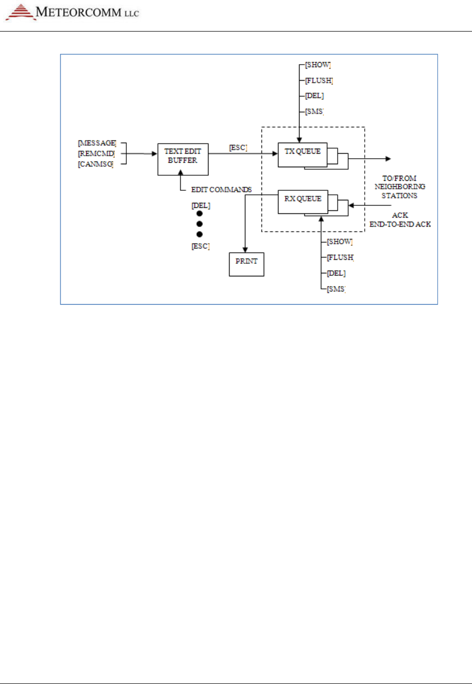
545C Operations Manual
02/10/2012 Prerelease DCN 00001789-A
© 2012 Meteorcomm LLC. All Rights Reserved. Proprietary and Confidential. Do Not Distribute. 65
Figure 14: Message flow and associated commands

545C Operations Manual
02/10/2012 Prerelease DCN 00001789-A
66 © 2012 Meteorcomm LLC. All Rights Reserved. Proprietary and Confidential. Do Not Distribute.
The following operations are explained in this section:
Section Operations
4.3.1
Entering and Deleting Messages
4.3.2
Editing Messages
4.3.3
Sending Messages
4.3.4
Sending Commands
4.3.5
Sending Canned Messages
4.3.6
Receiving Messages
4.3.7
Examining Message Status
4.3.8
Examining and Revising Message Queues
5.3.1 Entering and Deleting Messages
All messages are composed and edited in the Text Edit Buffer. Messages
may be up to 3,570 characters in length. When composing the message you
must press [ENTER] at the end of each 80 character line.
There is a default destination programmed into the MCC-545C during the
installation and initialization of the unit when it is first brought on-line in
the network. If a message is not given a specific destination it will be sent
to the default destination only.
To enter a message:
1. Type MESSAGE. The operator terminal responds with ENTER TEXT.
The MCC-545C will now be in Compose-and-Edit mode (as opposed to
normal Command-Line Entry mode).
2. Enter a message up to 3,570 characters in length, pressing [ENTER]
at the end of each 80 character line.
3. Press the [ESC] key. The message is transferred to a Transmit queue
and will be automatically transmitted to the default destination at a
priority level R.
02/10/2012
© 2012 Meteorcomm LLC. All Rights Reserved.
The following message is displayed on the operator terminal:
hh:mm:ss
Message No:
hh:mm:ss
ROUTING name :
If you wish to send a message to multiple destinations, and at a different
priority level, type:
MESSAGE
,p,dest1,dest2,...dest n
where: p
dest n
Note:
If you also want to send the
must enter its station numerical ID as one of the destination parameters
(“dest1”, “dest2”, etc.) as specified above.
There are three other special editing functions that may be used:
1.
To Retransmit the Previously E
To retransmit a previously entered message, simply press the [ESC] key
after the operator terminal prints
pressed.
The previous message entered into the Text Edit Buffer is then
sent to the destination
command.
2.
To Revise the Previously Entered Message
To revise a previously entered message, press [CTRL]
TEXT
prompt to revise a previously entered message or to recover from an
aborted session.
The
at the end of the message
3.
To Delete a Message
To delete a message after it has been placed in the Tx Queue, type:
DELMSG,ID:sss
where:
ID
sss
545C Operations Manual
Prerelease
DCN
© 2012 Meteorcomm LLC. All Rights Reserved.
Proprietary and Confidential. Do Not Distribute.
The following message is displayed on the operator terminal:
Message No:
name:ss,nnnn chars, nnn segments
ROUTING name :
sss TXT sss/nn TO: name
If you wish to send a message to multiple destinations, and at a different
priority level, type:
,p,dest1,dest2,...dest n
= any priority level from A (highest) to Z (lowest).
= numerical
ID of the stations to which the
message is routed.
If you also want to send the
message to your default destination, you
must enter its station numerical ID as one of the destination parameters
(“dest1”, “dest2”, etc.) as specified above.
There are three other special editing functions that may be used:
To Retransmit the Previously E
ntered Message
To retransmit a previously entered message, simply press the [ESC] key
after the operator terminal prints
ENTER TEXT
and before any other key is
The previous message entered into the Text Edit Buffer is then
sent to the destination
s that are now designated in the
MESSAGE
To Revise the Previously Entered Message
To revise a previously entered message, press [CTRL]
T
after the
prompt to revise a previously entered message or to recover from an
The
previous message is displayed, with the cursor placed
at the end of the message
.
You may now resume editing the message.
To Delete a Message
To delete a message after it has been placed in the Tx Queue, type:
ID
= numerical station ID
sss
= message serial number
545C Operations Manual
DCN
00001789-A
67
The following message is displayed on the operator terminal:
If you wish to send a message to multiple destinations, and at a different
= any priority level from A (highest) to Z (lowest).
ID of the stations to which the
message to your default destination, you
must enter its station numerical ID as one of the destination parameters
There are three other special editing functions that may be used:
To retransmit a previously entered message, simply press the [ESC] key
and before any other key is
The previous message entered into the Text Edit Buffer is then
MESSAGE
after the
ENTER
prompt to revise a previously entered message or to recover from an
previous message is displayed, with the cursor placed
You may now resume editing the message.
To delete a message after it has been placed in the Tx Queue, type:

545C Operations Manual
02/10/2012 Prerelease DCN 00001789-A
68 © 2012 Meteorcomm LLC. All Rights Reserved. Proprietary and Confidential. Do Not Distribute.
The operator terminal displays the date and time, followed by MESSAGE
DELETED.
5.3.2 Editing Messages
The following editing functions may be used from the keyboard while the
message is in the Text Edit Buffer.
Key Function
[DEL]
Dele
tes the last character entered.
[CTRL]R
Prints the current line of text on the next line down.
[CTRL]I
Performs a fixed tab function
\
Removes the current line from the edit buffer.
[ENTER]
Performs a carriage return and line feed.
[LF]
Performs a
carriage return and line feed.
[CTRL]X
Removes the current line from the edit buffer and places
the cursor at the end of the previous line.
[CTRL]T
Prints the contents of the edit buffer & puts cursor at the
end of text.
[CTRL]D
Erases the entire
contents of the edit buffer.
[CTRK]A
Aborts the edit mode and returns to the command mode.
A “+” indicates the command mode.
[ESC]
Leaves text edit mode and queues the message for
transmission.
5.3.3 Sending Messages
Messages are automatically stored for transmission with the [ESC] key. Each
message is placed in the Tx Queue according to its assigned priority.
Messages of equal priority are placed in the Tx Queue in the order received
from the Text Edit Buffer.
The following display appears on the operator terminal as the MCC-545C
stores and routes a message:
hh:mm:ss Message No: name:ss,nnnn chars, nnn segments

545C Operations Manual
02/10/2012 Prerelease DCN 00001789-A
© 2012 Meteorcomm LLC. All Rights Reserved. Proprietary and Confidential. Do Not Distribute. 69
hh:mm:ss ROUTING name :sss TXT sss/nn TO: name
Messages are transmitted in packets and are routed to their destination in a
Store-and-Forward manner, using the most efficient routing within the
packet switched network. The originating station receives an
acknowledgement (ACK) if the message has been received successfully by
the first routing station.
mm/dd/yy hh:mm:ss TXTMSG ACK name:sss, xxxx CHARS FROM name
When the entire message has been delivered to its final destination, the
operator terminal displays an end-to-end acknowledgement:
hh:mm:ss END-TO-END ACK OF name:sss FROM name
If the end-to-end ACK is not received within the specified time-to-live
limit, the MCC-545C purges the message from the Tx Queue and displays
the following message:
hh:mm:ss MESSAGE TIME-TO-LIVE EXPIRED, MSG.NO:sss, DESTN: name
You must then re-enter the message. Continued failure to successfully
transmit a message indicates that something may be wrong with the
equipment or the link (e.g., excessive noise interference).
5.3.4 Sending Commands
Commands may be sent to any station within the network. The entry of a
command is similar to the MESSAGE command described in Section 4.3.1.
REMCMD,R,dest1,dest2,...destn
where: R = priority level
dest = numerical ID of destination station(s)
The operator is then prompted to enter the text of the command using the
message editor. Once the command is entered, press the [ESC] key to send
the command. The operator terminal will display:
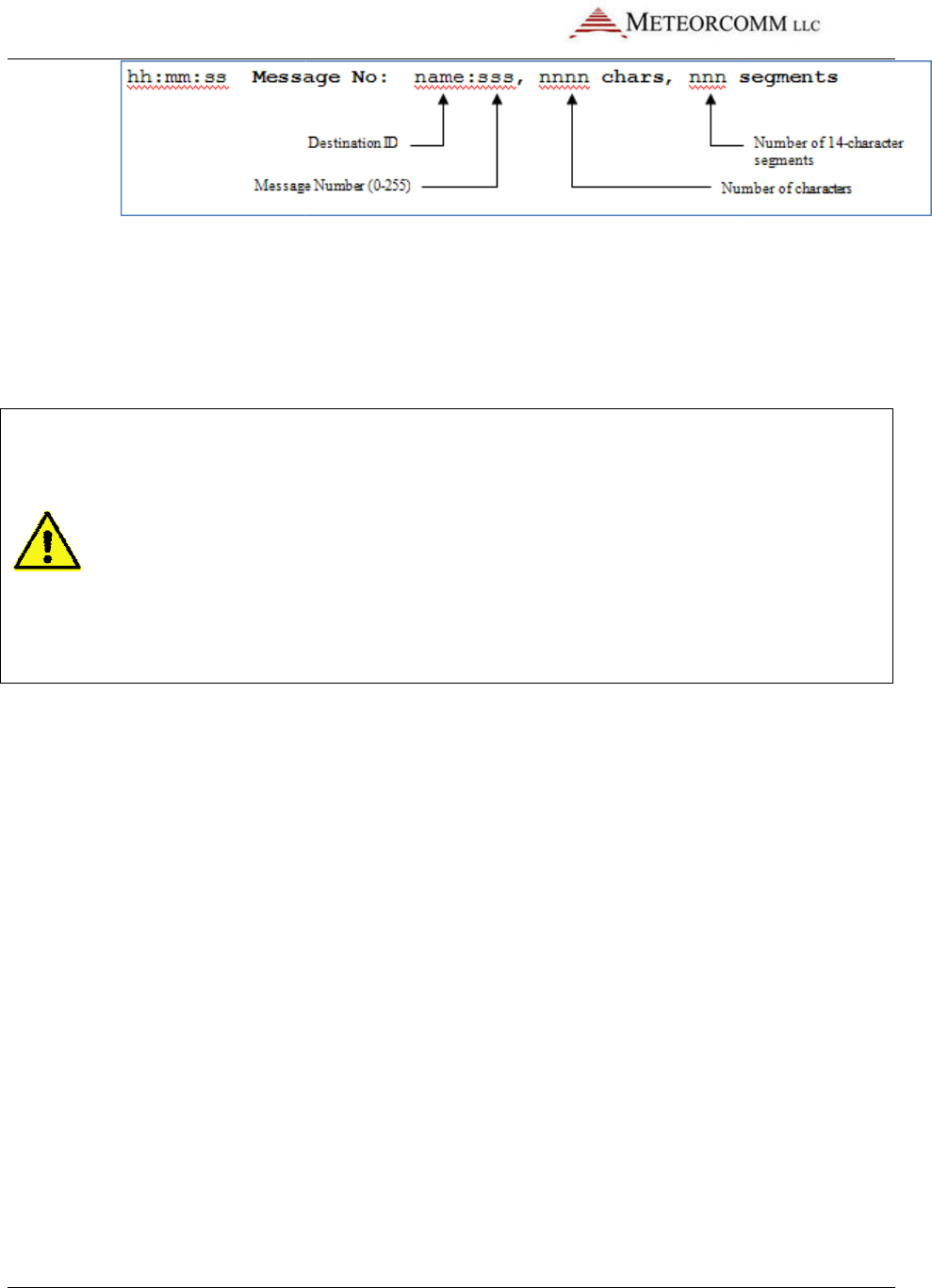
545C Operations Manual
02/10/2012
70
© 2012 Meteorcomm LLC.
A response is received from the destination station(s) if the command was
successfully received.
5.3.5
Sending Canned Messages
Important:
Do not use Canned Message mode except for laboratory test
The number of canned messages generated can quickly bring network
throughput to a stand
network. Canned messages displace data capacity, and may prevent
network users and stations from sending anythin
command to clear canned message queue(s).
The MCC-
545C may be placed into a canned message mode for automatic
transmission of a repetitive message to an assigned neighboring station
the canned message mode no more than 25
the Tx Queue at one time
message that is generated from the alphabet.
To enter a canned message generated from the alphabet, enter:
CANMSG
,id,mmmm{,qq}{,nnnn}
where:
id
mmmm
qq
nnnn
The default queue depth is 5
automatically injected if the number of canned messages in the queue falls
below the minimum queue depth.
Prerelease
DCN
© 2012 Meteorcomm LLC.
All Rights Reserved. Proprietary and Confidential. Do Not Distribute.
A response is received from the destination station(s) if the command was
successfully received.
Sending Canned Messages
Do not use Canned Message mode except for laboratory test
The number of canned messages generated can quickly bring network
throughput to a stand
-
still in an operational FleetTrak™ or Meteor Burst
network. Canned messages displace data capacity, and may prevent
network users and stations from sending anythin
g out. Use the
command to clear canned message queue(s).
545C may be placed into a canned message mode for automatic
transmission of a repetitive message to an assigned neighboring station
the canned message mode no more than 25
messages may be placed into
the Tx Queue at one time
.
You may either send an edited text message or a
message that is generated from the alphabet.
To enter a canned message generated from the alphabet, enter:
,id,mmmm{,qq}{,nnnn}
id
= neighboring station ID
= message length from 1 to 3000 characters
qq
= minimum queue depth from 1 to 25
nnnn
= total number of canned messages to generate
(maximum of 10,000)
The default queue depth is 5
.
Additional canned messages are
automatically injected if the number of canned messages in the queue falls
below the minimum queue depth.
DCN
00001789-A
All Rights Reserved. Proprietary and Confidential. Do Not Distribute.
A response is received from the destination station(s) if the command was
Do not use Canned Message mode except for laboratory test
ing!
The number of canned messages generated can quickly bring network
still in an operational FleetTrak™ or Meteor Burst
network. Canned messages displace data capacity, and may prevent
g out. Use the
CANMSGOFF
545C may be placed into a canned message mode for automatic
transmission of a repetitive message to an assigned neighboring station
. In
messages may be placed into
You may either send an edited text message or a
To enter a canned message generated from the alphabet, enter:
= message length from 1 to 3000 characters
= total number of canned messages to generate
Additional canned messages are
automatically injected if the number of canned messages in the queue falls

545C Operations Manual
02/10/2012 Prerelease DCN 00001789-A
© 2012 Meteorcomm LLC. All Rights Reserved. Proprietary and Confidential. Do Not Distribute. 71
If the Total parameter was entered, the canned message mode stops when
the desired number of messages has been transmitted.
To enter an edited canned message, enter:
CANMSG,id
where “id” is the neighboring station’s ID. After composing your message
press the [ESC] key. The MCC-545C automatically routes up to 25 copies of
the canned message to the destination station.
Each canned message is acknowledged by the selected neighboring station.
No end-to-end acknowledgements are received for canned messages.
To manually terminate the mode, enter:
CANMSG OFF,id
Canned messages are normally not printed at the destination station. To
print canned messages as they are received, enter:
CANMSG MODE,PRINT
To turn off the print mode, enter:
CANMSG MODE,NO PRINT
5.3.6 Receiving Messages
When a new message is received, it is announced by the following display:
hh:mm:ss RECEIVING name:sss TXT sss/nn FROM name ROUTED TO: name
The MCC-545C then generates an acknowledgement of the message packet
and transmits the ACK to the neighbor from whom the message was
received:
hh:mm:ss TXTMSG ACK name:sss, nnnn CHARS FROM name
When the destination MCC-545C receives a complete message, it displays
the following message:
hh:mm:ss MSG RECEIVED name:sss, xxxx CHARS
text..................
**end-of-message**
545C Operations Manual
02/10/2012
72
© 2012 Meteorcomm LLC.
where “name:sss
” is the message serial number.
Messages are deleted as they are displayed
forwarded to further destinations.
5.3.7
Examining Message Status
The status of all messages may be examined while they are still in the Tx
Queue.
To examine the status messages destined for a particular station,
enter:
SMS{,id}
where:
id
Note: Once an end-
to
deleted from the queue.
5.3.8
Examining and Revising Message Queues
There are two types of queues for transmitting and receiving messages:
Queue name
Description
TXQ
(Transmit
Queue)
This queue is used for transmitting all messages. There is a separate
transmit queue for each neighboring station in the network. For
example, if you enter a message for DEST1, that message is placed in
DEST1’s transmit qu
RXQ
(Receive
Queue)
This queue is used for all received messages. There is a separate
receive queue for each neighboring station in the network. For
example, to examine message statistics from NODE5, examine the
receive queue from NODE5.
To examine
the contents of either queue, type:
SHOW TXQ
,id
You must specify the queue by entering the station ID
TXQ,006
displays statistics for all messages being transmitted to station
006.
You can only examine the receive and
stations in the network.
Prerelease
DCN
© 2012 Meteorcomm LLC.
All Rights Reserved. Proprietary and Confidential. Do Not Distribute.
” is the message serial number.
Messages are deleted as they are displayed
or printed unless they are being
forwarded to further destinations.
Examining Message Status
The status of all messages may be examined while they are still in the Tx
To examine the status messages destined for a particular station,
id
= station ID
to
-
end acknowledgement is received for a message, it is
deleted from the queue.
Examining and Revising Message Queues
There are two types of queues for transmitting and receiving messages:
Description
This queue is used for transmitting all messages. There is a separate
transmit queue for each neighboring station in the network. For
example, if you enter a message for DEST1, that message is placed in
DEST1’s transmit qu
eue.
This queue is used for all received messages. There is a separate
receive queue for each neighboring station in the network. For
example, to examine message statistics from NODE5, examine the
receive queue from NODE5.
the contents of either queue, type:
,id
or SHOW RXQ,id
You must specify the queue by entering the station ID
.
For example,
displays statistics for all messages being transmitted to station
You can only examine the receive and
transmit queues for neighbor
stations in the network.
DCN
00001789-A
All Rights Reserved. Proprietary and Confidential. Do Not Distribute.
or printed unless they are being
The status of all messages may be examined while they are still in the Tx
To examine the status messages destined for a particular station,
end acknowledgement is received for a message, it is
There are two types of queues for transmitting and receiving messages:
This queue is used for transmitting all messages. There is a separate
transmit queue for each neighboring station in the network. For
example, if you enter a message for DEST1, that message is placed in
This queue is used for all received messages. There is a separate
receive queue for each neighboring station in the network. For
example, to examine message statistics from NODE5, examine the
For example,
SHOW
displays statistics for all messages being transmitted to station
transmit queues for neighbor

545C Operations Manual
02/10/2012 Prerelease DCN 00001789-A
© 2012 Meteorcomm LLC. All Rights Reserved. Proprietary and Confidential. Do Not Distribute. 73
To delete the contents of the transmit and receive queues, you must
specify the exact queue by entering a station name:
FLUSH TXQ,id or FLUSH RXQ,id
For each message deleted, the terminal displays:
id:sss unlinked {and deleted}
The “and deleted” text appears only if the message is not present in
another queue. When all messages have been deleted, the terminal
displays:
queue flushed
To delete a specific message, enter:
DEL MSG,id:sss
The terminal displays:
Message deleted
To delete all messages from all queues, enter:
FLUSH MSG
For each message deleted, the terminal displays:
id:sss deleted
Entering the FLUSH MSG command deletes all messages in all queues for
every node of the network, including connectivity and end-to-end
acknowledgment messages.
5.4 GPS Position Reporting
The MCC-545C automatically transmits position reports derived from either
an external GPS receiver or from its own internal GPS receiver. The
appropriate script file must be loaded into the MCC-545C that allows it to
interface to the protocol used by a particular GPS. The NMEA 0183 Version
2.0 protocol is used in this section for descriptive purposes only. Please
consult MCC regarding script files for other protocols.

545C Operations Manual
02/10/2012 Prerelease DCN 00001789-A
74 © 2012 Meteorcomm LLC. All Rights Reserved. Proprietary and Confidential. Do Not Distribute.
The MCC-545C will accept either a TTL or an RS-232 input from a GPS
receiver. The internal GPS uses the TTL interface and its output is
internally routed to the processor board assembly. If an external GPS is
used it may be connected to either the AUX port or the Data port using the
RS-232 interface.
5.4.1 Position Reporting Commands
The following commands are normally in a script file and are used for
configuring the MCC-545C for position reporting.
Command Description
ASSIGN,POS,p,GPS
Port selection for transmission of GPS
data.
p = Selects the desired port:
2 = External AUX, RS-232
3 = Internal TTL
SETBAUD,POS,4800,N,8,1
Set up parameters for the selected port
.
For example:
4800 = Baud rate
N = Parity
8 = Data Bits
1 = Stop Bit
POS,nn,TEXT,NMEA nn
=
Transmit interval in seconds of a position
report to the system host.
TEXT = Binary Text
NEMA = Protocol type
Note: Each time a report is transmitted to the Host it
may also be sent to one of the local ports.
POS,LOCAL,nn nn
=
The time interval
in seconds between reports
sent to a local port.
Note: This feature is used when more frequent position
reports are desired on a local operator terminal than
are being sent to the Host.
POSRPT,ON ON
=
Used to display position reports from other
remotes on a local operator terminal.
OFF = Disable

545C Operations Manual
02/10/2012 Prerelease DCN 00001789-A
© 2012 Meteorcomm LLC. All Rights Reserved. Proprietary and Confidential. Do Not Distribute. 75
5.4.2 Differential GPS
MBNET200 (ELOS protocol) may be used to broadcast differential correction
data to all Remote Stations in the network. This eliminates the need for
having a differential GPS receiver at each MCC-545C mobile unit.
Differential beacon receivers are installed at base or repeater stations
only. The base stations then transmit the RTCM correction data at periodic
intervals to all repeaters and mobiles.
The ASSIGN and SETBAUD commands are used to configure the base stations
to use a beacon receiver.
Command Description
ASSIGN,POS,p,RTCM,nn
Port selection for transmission of RTCM data.
P = Port number, normally AUX port (2)
is used.
Nn = The interval, in seconds, that the
RTCM error correction data is
transmitted. A value of 20 seconds
provides reasonable accuracy.
SETBAUD,POS,4800,N,8,1
Set up parameters for the selected port
.
For example:
4800 = Baud rate
N = Parity
8 = Data Bits
1 = Stop Bit
A remote station will automatically receive and process the RTCM
correction data. No other configuration commands are required.
5.4.3 GPS Report Formats
There are two position report formats used. The POS format is the basic
report and has latitude, longitude, speed, heading and altitude. The POSS
format includes all the information above but also has a 16-bit status word
and an 8-bit code for appending canned messages. An example of each type
of format is shown in Figure 4.2.
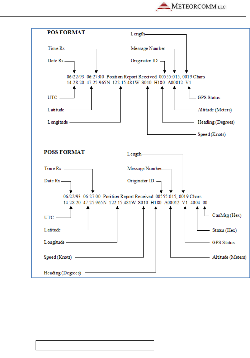
545C Operations Manual
02/10/2012 Prerelease DCN 00001789-A
76 © 2012 Meteorcomm LLC. All Rights Reserved. Proprietary and Confidential. Do Not Distribute.
Figure 15: Position report formats
The Status bit field is application dependent and is normally defined by the
user. For non-maritime applications speed is converted from knots to MPH
on the operator’s display.
The GPS status bits define if the GPS receiver is locked and the accuracy of
the data.
V0
GPS not locked; position data is not valid.

545C Operations Manual
02/10/2012 Prerelease DCN 00001789-A
© 2012 Meteorcomm LLC. All Rights Reserved. Proprietary and Confidential. Do Not Distribute. 77
V1
GPS locked without differential correction.
V2
GPS locked with differential correction.
Standard V1 accuracy will be about ±10 meters. V2 accuracy will normally
be ±2 meters and is dependent on the RTCM broadcast rate and the
distance between the mobile and the nearest base station.
5.4.4 GPS Receiver Setup
The setup procedure for a GPS receiver is generally different for each
manufacturer’s type. Connect a laptop or PC to the GPS receiver for
entering the desired sentences and update interval. A NMEA type GPS must
be configured as follows:
Type of sentence
Update interval
Status
GPRMC 1 second
Required
GPGGA 1 second
Required
GPVTG 1 second
Optional
The TRACE command may be used to verify correct GPS operation:
TRACE,ON,GPS
All characters received will be displayed on the Operator Port, including
sentence types. Verification that the position report is being transmitted at
the desired POS,nn interval may also be observed.
To disable the display output, enter:
TRACE,OFF
5.4.5 Position Reporting in Subnets
The SUBNET command assigns a subnet code number from 1-255. The code
number is maintained in the locked configuration parameter list along with
the serial number, customer number and frequency table. The command
formats are:
SUBNET
Display current subnet setting
SUBNET,OFF
Turn off the subnet number (must be unlocked)
SUBNET,nnn
Define a subnet number (must be unlocked)

545C Operations Manual
02/10/2012
78
© 2012 Meteorcomm LLC.
After entering a subnet number and all the other configuration items, ent
LOCK,CONFIG
to lock the current setting.
The SUBNET
command is used in conjunction with the
command to limit the position reports that can be received to only those
transmitted by other units with the same subnet code or any Base or
Repeater. If
SUBNET
The default setting is
Messages and remote commands are
sent to or received from any other unit.
Important: The
$PENTM,ON
format reports, which will include the 16
(The SUBNET ID
replaces the MCC
SUBNET and
$PENTM,ON
5.5
Supervisory Control and Data Acquisition
The MCC-
545C is designed to perform a supervisory control and data
acquisition (SCADA) function using one of three modes
Sensor I/O Port
External Data Loggers
Direct Mode Protocol
This section covers these three m
operations, including defining Data Relays, the
to read the MCC-
545C’s internal sensor values, and details on the
data logger device drivers.
5.5.1 Sensor Port
A limited SCADA capability is built in fo
logger capability is not required
Prerelease
DCN
© 2012 Meteorcomm LLC.
All Rights Reserved. Proprietary and Confidential. Do Not Distribute.
After entering a subnet number and all the other configuration items, ent
to lock the current setting.
command is used in conjunction with the
$PENTM,ON
command to limit the position reports that can be received to only those
transmitted by other units with the same subnet code or any Base or
SUBNET
is OFF
, then the unit can receive all position reports.
The default setting is
OFF.
Messages and remote commands are
not
limited to the subnet and can be
sent to or received from any other unit.
$PENTM,ON
command must be entered to enable the POSS
format reports, which will include the 16
-bit status and 8-bit
SUBNET ID
replaces the MCC
-
545C’s “normal” canned message.) Using
$PENTM,ON
precludes the use of canned message mode.
Supervisory Control and Data Acquisition
545C is designed to perform a supervisory control and data
acquisition (SCADA) function using one of three modes
:
External Data Loggers
Direct Mode Protocol
This section covers these three m
odes, plus more advanced SCADA
operations, including defining Data Relays, the
PASSTHRU
command, how
545C’s internal sensor values, and details on the
data logger device drivers.
A limited SCADA capability is built in fo
r those applications when a full data
logger capability is not required
.
The following capability is provided:
DCN
00001789-A
All Rights Reserved. Proprietary and Confidential. Do Not Distribute.
After entering a subnet number and all the other configuration items, ent
er
$PENTM,ON
command to limit the position reports that can be received to only those
transmitted by other units with the same subnet code or any Base or
, then the unit can receive all position reports.
limited to the subnet and can be
command must be entered to enable the POSS
SUBNET ID
.
545C’s “normal” canned message.) Using
precludes the use of canned message mode.
545C is designed to perform a supervisory control and data
odes, plus more advanced SCADA
command, how
545C’s internal sensor values, and details on the
GENERIC
r those applications when a full data
The following capability is provided:

545C Operations Manual
02/10/2012 Prerelease DCN 00001789-A
© 2012 Meteorcomm LLC. All Rights Reserved. Proprietary and Confidential. Do Not Distribute. 79
• 4 optically isolated inputs for discrete ON/OFF functions
• 6 analog voltage inputs (0 to 5V)
• 2 SPDT Form C relay outputs
In addition,±12VDC is supplied for sensor power and a +5V reference
voltage for sensor excitation is available.
The Sensor port interface is a 25-pin male D connector. The connector
pinouts and their respective functions are shown below.
The analog voltages are routed to a 10-bit analog-to-digital converter (ADC)
which provides a resolution of +/-.1% and an accuracy over temperature of
±0.5%.
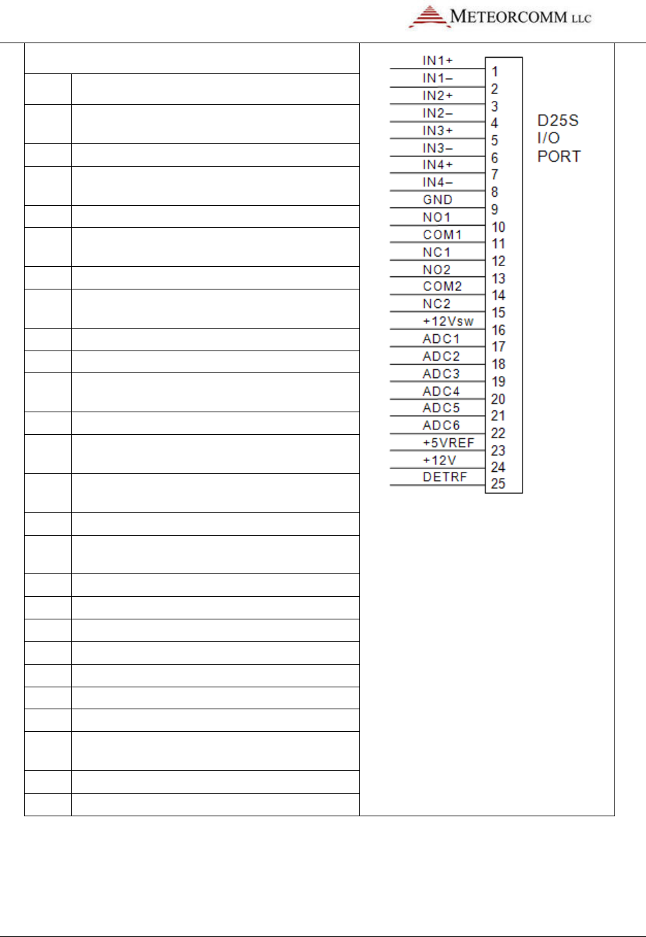
545C Operations Manual
02/10/2012 Prerelease DCN 00001789-A
80 © 2012 Meteorcomm LLC. All Rights Reserved. Proprietary and Confidential. Do Not Distribute.
SENSOR PORT
Pin Signal
1
Optocoupled input #1 positive
(500 ohm resistor)
2
Optocoupled input #1 return
3
Optocoupled
input #2 positive
(500 ohm resistor)
4
Optocoupled input #2 return
5
Optocoupled input #3 positive
(500 ohm resistor)
6 Optocoupled input #3 return
7
Optocoupled input #4 positive
(500 ohm resistor)
8
Optocoupled input #4 return
9
Ground
10
Relay Output #1 Normally Open
(2 Amp rating)
11
Relay Output #1 Common
12
Relay Output #1 Normally Closed
(2 Amp rating)
13
Relay Output #2 Normally Open
(2 Amp rating)
14
Relay Output #2 Common
15
Relay Output #2 Normally Closed
(2 Amp rating)
16
Switched +12V (battery)
17
Analog Input #1 ( 0 to 5 V)
18
Analog Input #2 ( 0 to 5 V)
19
Analog Input #3 ( 0 to 5 V)
20
Analog Input #4 ( 0 to 5 V)
21
Analog Input #5 ( 0 to 5 V)
22
Analog Input #6 ( 0 to 5 V)
23
+5V Reference
(10mA for sensor excitation)
24
+12V (0.5A maximum)
25
Detected RF Test Point
A 25-pin terminal block is a convenient means for interfacing to the various
sensors and control points.

02/10/2012
© 2012 Meteorcomm LLC. All Rights Reserved.
Note: In -
03 series or later radios, the Sensor I/O connector pin #16 has
been changed from ground to a switched +12 volt (battery). This switched
+12 volt can be used to drive sensors. The total current load on the +12 volt
and switched +12 volt must not exceed
control the +12 volt switched output (see Section 4.6)
5.5.2
External Data Loggers
Any data logger that MCC supports and has an RS
connected to any one of the 3 ports on the MCC
or
AUX Port is used
connector:
Pin
Function
2
TX Data
3
RX Data
5
Ground
Three commands are required to configure the Data Port for proper
operation with the particular data logger being used:
ASSIGN
,DTA,OFF
ASSIGN,DTA,1,
SETBAUD,DTA,9600
The first command clears any previous assignments that still may be in
effect for the DTA Port
data logger and protocol to the DTA Port
rate for the DTA Port
may be obtained from MCC or your System Administrator.
5.5.3
Direct Mode Protocol
The DIRECT MODE
a peripheral device conne
anywhere within the FleetTrak
directly through the MCC
data to its destination in the same format as it was entered at the sou
545C Operations Manual
Prerelease
DCN
© 2012 Meteorcomm LLC. All Rights Reserved.
Proprietary and Confidential. Do Not Distribute.
03 series or later radios, the Sensor I/O connector pin #16 has
been changed from ground to a switched +12 volt (battery). This switched
+12 volt can be used to drive sensors. The total current load on the +12 volt
and switched +12 volt must not exceed
500mA. Use EVENT
programming to
control the +12 volt switched output (see Section 4.6)
External Data Loggers
Any data logger that MCC supports and has an RS
-
232 interface may be
connected to any one of the 3 ports on the MCC
-545C.
Normally, the Data
AUX Port is used
.
You may connect to either port using a 9
Three commands are required to configure the Data Port for proper
operation with the particular data logger being used:
,DTA,OFF
ASSIGN,DTA,1,
type
SETBAUD,DTA,9600
The first command clears any previous assignments that still may be in
effect for the DTA Port
.
The second command assigns a specific type of
data logger and protocol to the DTA Port
.
The third command sets the
rate for the DTA Port
.
The specific type of data loggers that MCC supports
may be obtained from MCC or your System Administrator.
Direct Mode Protocol
DIRECT MODE
protocol is used for the transmission of binary data from
a peripheral device conne
cted to one of the MCC-
545C’s serial ports t
anywhere within the FleetTrak
network.
The serial data stream passes
directly through the MCC
-
545C in a “transparent” mode, delivering the
data to its destination in the same format as it was entered at the sou
545C Operations Manual
DCN
00001789-A
81
03 series or later radios, the Sensor I/O connector pin #16 has
been changed from ground to a switched +12 volt (battery). This switched
+12 volt can be used to drive sensors. The total current load on the +12 volt
programming to
232 interface may be
Normally, the Data
You may connect to either port using a 9
-pin “D” type
Three commands are required to configure the Data Port for proper
The first command clears any previous assignments that still may be in
The second command assigns a specific type of
The third command sets the
baud
The specific type of data loggers that MCC supports
protocol is used for the transmission of binary data from
545C’s serial ports t
o
The serial data stream passes
545C in a “transparent” mode, delivering the
data to its destination in the same format as it was entered at the sou
rce.

545C Operations Manual
02/10/2012
82
© 2012 Meteorcomm LLC.
The serial data stream may originate from a data logger, message device,
or any peripheral that has an RS
Note: The
DIRECT MODE
networks, especially with external data loggers.
DIRECT MODE
operation is similar to a “terminal server” on PC Ethernet
Networks.
The MCC
on one of its ports (Operator, Data, or AUX), packetizes the data into
message segments and transmits it to one or more dest
the CSMA mode.
The throughput rate will be dependent on channel
availability at the time of transmission.
The DIRECT
protocol is general in nature and allows the connecting
equipment at the source and destination to manage all error co
FleetTrak
message acknowledgement protocol can also be used as an
option to ensure reliability of message delivery
selected using the
ASSIGN,DTA,1,DIRECT,30
This command would s
with a 30 second time out connection
independently and operate simultaneously.
Connection Management
A connection between the external equipment and the MCC
us
ing a “connect string.” The transfer then begins and continues until the
connection is terminated
assumed to exist and the data is then automatically routed through the
network to the destination equipment
connection: a permanent connection or an ad hoc connection.
Permanent Connection
The permanent connection is made by setting the connect string
keeps the port open at all times and all characters received will
au
tomatically be transmitted
port and the connection does not terminate
received from the destination will be routed to the local port for printing.
Prerelease
DCN
© 2012 Meteorcomm LLC.
All Rights Reserved. Proprietary and Confidential. Do Not Distribute.
The serial data stream may originate from a data logger, message device,
or any peripheral that has an RS
-232 interface.
DIRECT MODE
protocol can also be used in Meteor Burst
networks, especially with external data loggers.
operation is similar to a “terminal server” on PC Ethernet
The MCC
-
545C will accept any stream of unformatted characters
on one of its ports (Operator, Data, or AUX), packetizes the data into
message segments and transmits it to one or more dest
ination addresses in
The throughput rate will be dependent on channel
availability at the time of transmission.
protocol is general in nature and allows the connecting
equipment at the source and destination to manage all error co
message acknowledgement protocol can also be used as an
option to ensure reliability of message delivery
. The DIRECT
selected using the
ASSIGN
command, as shown in this example:
ASSIGN,DTA,1,DIRECT,30
This command would s
et up DATA port 1 to use the DIRECT
protocol mode
with a 30 second time out connection
.
Any, or all, ports can be set up
independently and operate simultaneously.
A connection between the external equipment and the MCC
-
545C is made
ing a “connect string.” The transfer then begins and continues until the
connection is terminated
.
The proper connections at the destination are
assumed to exist and the data is then automatically routed through the
network to the destination equipment
. T
here are two ways to establish a
connection: a permanent connection or an ad hoc connection.
The permanent connection is made by setting the connect string
keeps the port open at all times and all characters received will
tomatically be transmitted
.
A connect string is not required to open the
port and the connection does not terminate
.
Likewise, all characters
received from the destination will be routed to the local port for printing.
DCN
00001789-A
All Rights Reserved. Proprietary and Confidential. Do Not Distribute.
The serial data stream may originate from a data logger, message device,
protocol can also be used in Meteor Burst
operation is similar to a “terminal server” on PC Ethernet
545C will accept any stream of unformatted characters
on one of its ports (Operator, Data, or AUX), packetizes the data into
ination addresses in
The throughput rate will be dependent on channel
protocol is general in nature and allows the connecting
equipment at the source and destination to manage all error co
ntrol. The
message acknowledgement protocol can also be used as an
protocol is
command, as shown in this example:
protocol mode
Any, or all, ports can be set up
545C is made
ing a “connect string.” The transfer then begins and continues until the
The proper connections at the destination are
assumed to exist and the data is then automatically routed through the
here are two ways to establish a
connection: a permanent connection or an ad hoc connection.
The permanent connection is made by setting the connect string
OFF. This
keeps the port open at all times and all characters received will
A connect string is not required to open the
Likewise, all characters
received from the destination will be routed to the local port for printing.

545C Operations Manual
02/10/2012 Prerelease DCN 00001789-A
© 2012 Meteorcomm LLC. All Rights Reserved. Proprietary and Confidential. Do Not Distribute. 83
Ad Hoc Connection
A connect string from 1 to 19 characters is used to open a connection on an
ad hoc basis. The connection will remain open for as long as characters are
being received or the connection times-out, whichever occurs first. Once
the connection times-out it must be reestablished.
If the connect string is unknown, the command ANY will open the
connection for any string of characters.
Connect Response
A connect response string may be enabled so that the peripheral device
initiating the message will receive confirmation that the connection has
been made. If the connect response string is turned OFF then no response
will be sent when the connection is made.
Message Management
A message may be as long as 3,500 characters. Each message is assigned a
sequence number and is broken up into a number of packets. A message
header is inserted into each message ahead of the first data character.
$DIR,p,m,s,n
where: p = the assigned port to which the message is directed.
m = the message sequence number from 1-2554
s = the packet sequence number in a multi-packet message
n = total number of packets in a message
A message will be appended with either a terminator character or a
maximum character count. The message will be terminated by either one
of these characters or the “time-out” whichever occurs first.
Shorter messages are normally contained in a single packet with the s,n
parameters set for 1,1. Longer messages will have several packets
contained within the same message number “m”. The “s” parameter for
each packet will be incremented but the “n” parameter will be set to 0.
The true “n” value is only transmitted with the last packet in the message.
For example, for a 3 packet message the s,n and m parameters will be as
follows:
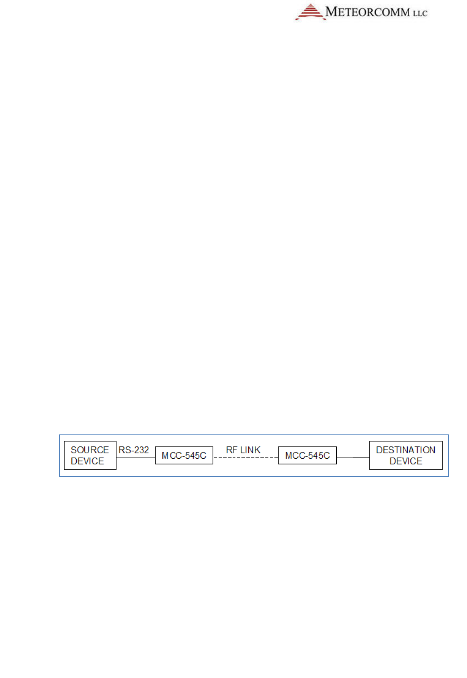
545C Operations Manual
02/10/2012 Prerelease DCN 00001789-A
84 © 2012 Meteorcomm LLC. All Rights Reserved. Proprietary and Confidential. Do Not Distribute.
$DIR, p, m, s, n
Packet 1 1 1 0
Packet 2 1 2 0
Packet 3 1 3 3
Messages may be transmitted from one to four destinations. When a
DIRECT message is received at the destination MCC-545C, it will be routed
to the assigned port(s) (Operator, Data or AUX). There are two types of
connections that may be used: point-to-point and multi-point-to-single-
point.
Point-to-Point
In the point-to-point mode the destination MCC-545C must also be pre-
programmed in the DIRECT mode. When the message is received at the
destinations, the $DIR,p,m,s,n header will be removed from the message
and the message will be routed to the same port that was used at the
source. That is, messages that were originated on Port 1 must also be
routed to Port 1 at the destination.
The destination unit can respond with its own character stream back to the
source. This provides a direct point-to-point, bi-directional channel
between the two stations. The embedded ETE acknowledgement in the
ELOS protocol may be used for ensuring message delivery.
Multi-Point-to-Single-Point
Many remotes can be set up to operate in the DIRECT mode, all routing
their data to a common destination (base station or Host). The destination
station does not have to be pre-programmed in the DIRECT mode as in the
point-to-point case. The destination station will treat the message as it
would for any other text message, using one of the many available port
protocols. The message header, $DIR,p,m,s,n, is retained with the message
so that the destination station will know how to format a return message to
the source station. In this manner, the Host can send response packets to
all sources by appropriately formatting the message header.
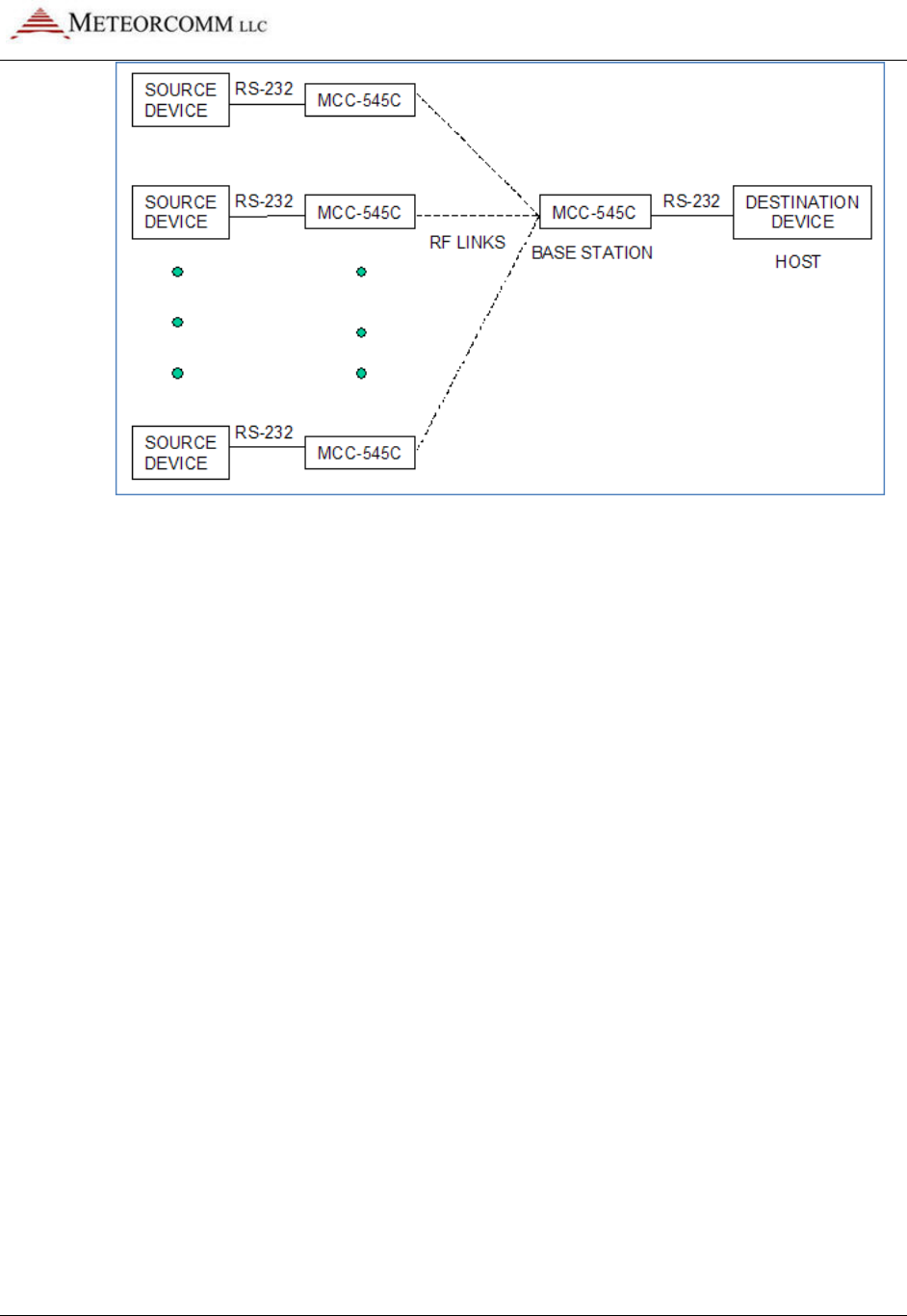
545C Operations Manual
02/10/2012 Prerelease DCN 00001789-A
© 2012 Meteorcomm LLC. All Rights Reserved. Proprietary and Confidential. Do Not Distribute. 85
Messaging Options and Commands
Various options may be set up in the MCC-545C using the command DIRECT
with the parameters shown in the following list. Each command is briefly
described below:
Command List:
DIRECT
DIRECT, p, CONNECT STRING, OFF
DIRECT, p, CONNECT STRING, ANY
DIRECT, p, CONNECT STRING, connect-text-string
DIRECT, p, CONNECT RESPONSE, OFF
DIRECT, p, CONNECT RESPONSE, response-text-string
DIRECT, p, PACKET TIMEOUT, decimal-timeout-ticks
DIRECT, p, PACKET TERMINATOR, OFF
DIRECT, p, PACKET TERMINATOR, decimal-char-code
DIRECT, p, MAX PACKET, length
DIRECT, p, ETE, ON
DIRECT, p, ETE, OFF
Command Detailed Descriptions:
DIRECT
When used without any parameters the current port settings will be
displayed

545C Operations Manual
02/10/2012 Prerelease DCN 00001789-A
86 © 2012 Meteorcomm LLC. All Rights Reserved. Proprietary and Confidential. Do Not Distribute.
DIRECT, p, CONNECT STRING, OFF
Disables the connect string option. The MCC-545C will not expect a
connect string and will stay connected all the time.
DIRECT, p, CONNECT STRING, connect-text-string
Defines a text string of up to 19 characters that is output by the external
equipment to establish a connection with the MCC-545C DIRECT port
task. The MCC-545C will receive the connect string and output the
connect response string if one is defined.
DIRECT, p, CONNECT STRING, ANY
Defines that any unspecified text string will be acceptable to establish a
connection.
DIRECT, p, CONNECT RESPONSE, OFF
Disables the response string option.
DIRECT, p, CONNECT RESPONSE, response-text-string
Defines a text string to be output by the MCC-545C to the external
equipment to confirm a connection has been established.
DIRECT, p, PACKET TIMEOUT, decimal-timeout-ticks
Defines the timeout period in 1/16 second clock increments that marks
the end of a packet. After each character of the packet is received the
timer is reset. After the last character has been received and the
timeout passed, the characters received will be placed in a message and
queued for transmission.
DIRECT, p, PACKET TERMINATOR, OFF
Disables packet termination using a specified character code.
DIRECT, p, PACKET TERMINATOR, decimal-char-code
Enables packet termination when the given character code is received.
For example, using a carriage return to terminate each packet will
transmit each line of input as a separate message. The decimal code for
carriage return is 13. The decimal code for linefeed is 10.
DIRECT, p, MAX PACKET, length

545C Operations Manual
02/10/2012 Prerelease DCN 00001789-A
© 2012 Meteorcomm LLC. All Rights Reserved. Proprietary and Confidential. Do Not Distribute. 87
Defines the maximum length of a message. As characters are received
they are filled into a buffer and when the maximum size is reached a
new message is transmitted. The longest message that can be used by
the MCC-545C is 3,500 characters.
DIRECT, p, ETE, ON
Defines the “reliable” type of message delivery. The source unit will
retain each transmitted message and periodically retry them until the
destination unit receives them and sends an end-to-end-
acknowledgement for each message. It is possible for messages to be
delivered out of sequence when a retry has occurred causing duplicate
messages. These duplicate messages will be filtered out.
DIRECT, p, ETE, OFF
Disables the “reliable” type of message delivery. The source unit will
not retain each transmitted message for retries. Each message will be
deleted as soon as transmitted. It will be the responsibility of any
receiving equipment to manage the message reliability. If any message
gets lost in the RF network, then all characters in that message will be
lost.
5.5.4 Defining Data Relays
The ambient noise conditions at a remote station site may sometimes be
excessive and a poor communication path to the Master Station will result
particularly if the remote station is operating in a meteor burst mode. To
overcome this problem, another MCC-545C may be placed in a nearby quiet
location and used as relay station between the MCC-545C at the noisy site
and its master station. When used as a relay, the MCC-545C will
concentrate the data reports it receives from one or more neighboring
remote sites and forwards the data to the Master Station.
When used in the relay mode, the MCC-545C must be defined as a Master
Station. The relay will then receive MCC-550C sensor data GROUP reports
(see MCC-550C Operations Manual), repackage them and forward them to
the Master Station. A relay can handle a total of sixteen GROUP reports.
These reports can be in any combination; i.e., four groups from each of
four Remote units, one group from each of sixteen Remote units or any

545C Operations Manual
02/10/2012 Prerelease DCN 00001789-A
88 © 2012 Meteorcomm LLC. All Rights Reserved. Proprietary and Confidential. Do Not Distribute.
combination in between. Substitution tables must be established in both
the relay unit and also at the Master Station to manage the relay function.
When a designated GROUP report is received at the relay, it will substitute
its own ID and group number in the report as defined in its substitution
table and forward the data to a MCC-520B Master Station using the MCC-
550C RF format rather than the standard MCC-545C message format. When
the relayed data is received at the MCC-520B it reconstructs the original
data report based on its own substitution table and route the report as
required.
The following command is used to define the entries in the substitution
table for a relay unit:
SUBST,relay_id,relay_group,remote_id,remote_group
where: relay_id = relay unit’s ID
relay_group = data group report number at the relay
remote_id = originating Remote unit’s ID
remote_group = data group report number at the
originating Remote unit
5.5.5 I/O Port PASSTHRU
The PASSTHRU command allows a bi-directional connection to be made
between the different I/O ports of the MCC-545C. This will allow the
operator to configure one port to be connected to another port in a direct
ASCII mode where any characters coming in on one port will go out on the
other port, and vise-versa. For example: the command PASSTHRU,1,2
allows characters entered on port 1 to go out port 2, and characters
received on port 2 will go out port 1. There can be from 0 to 2 different
pass-through connections defined at any time. All ports given in a pass-
through connection must be assigned to some protocol and baud rate
before entering the PASSTHRU command. An error will be displayed if they
are not.

545C Operations Manual
02/10/2012 Prerelease DCN 00001789-A
© 2012 Meteorcomm LLC. All Rights Reserved. Proprietary and Confidential. Do Not Distribute. 89
Data coming in from a passed-through port will not be passed to the
assigned protocol driver and will be sent out the “other” port of the
connection.
The connection can be turned off by entering PASSTHRU,OFF,n where “n”
is either port in the connection. In addition either port in a pass-through
connection can output the string PASSTHRU,OFF to close its own
connection. The first method can be used from the operator port to close a
connection of other ports. The second method is used by the operator port
if it is one of the ports in the pass-through connection.
If port 1 is assigned to a CR10X driver, and port 0 is the operator port, then
the command PASSTHRU,0,1 allows the operator port to be connected
directly to the CR10X. One can then use XTermW or PC208 to talk to the
CR10X via the operator port without re-connecting cables.
5.5.6 Internal Sensor Values
The new MCC-545C -03 and later radios have the capability to read a
number of internal sensor values. These include:
• Internal temperature of the MCC-545C unit
• Internal rechargeable battery level
• External battery levels (loaded and unloaded)
These sensor values can be read using the EVENT command – refer to
Section 4.6.8 for details on how to program the MCC-545C to read these
values.
5.5.7 Generic Data Logger
The MCC-545 family of RF Modems includes a set of device drivers for its
serial ports. These have been customized for various external devices,
depending on the device requirements. The SDATA command allows a
simple text-based interface to send data groups to the MCC-545C for
transmission to the master. Any customer who can configure their data
report to meet this format can interface their data logger with no change
in the MCC-545C software. From 1 to 16 groups can be input, and there can
be from 1 to 16 sensors per group. Each sensor data value is formatted into

545C Operations Manual
02/10/2012 Prerelease DCN 00001789-A
90 © 2012 Meteorcomm LLC. All Rights Reserved. Proprietary and Confidential. Do Not Distribute.
a 16-bit binary value for transmission, then converted to engineering units
by the Data Center or Host software.
Some date loggers have a complex and non-configurable interface protocol,
and cannot meet any of the currently implemented protocols, but they can
output data reports on a serial port as if it were connected to a line
printer. The GENERIC data logger driver has been created for this type of
interface. Some things can be setup by user commands to configure the
report parsing, within a limited set of constraints, and allow the MCC-545C
to create SDATA type messages from the ASCII text reports.
The following sections describe what can be done to adapt the MCC-545C
to a variety of report formats.
Typical Report Formats
A typical report printed by a data logger has one line, or a set of lines for
each report. There are usually two types, single-line reports, and multiple-
line reports. An example of each type would be as shown below:
Single line report examples:
123.4 19.8 33 99 -1089.45 ...<cr><lf>
or
10/14/02 09:15:00 +123.4 +19.8 +33 +99 -1089.45 ...<cr><lf>
Note that the report ends with carriage return and linefeed characters, and
may or may not display a date and/or time. The data fields are usually
separated by blanks, and the data values may or may not contain a sign or
decimal point. The line is usually output by the data logger as the report is
placed into the devices' memory in real-time. There is no provision for
error checking, but if the serial port cable is wired correctly with shielding,
etc., it may be reliable enough.
Multiple line report examples:
No Time Tag With Time Tag With Sensor Labels
123.4<cr><lf>
10/14/02 09:15:00<cr><lf>
Date/Time: 10/14/02 09:15:00<cr><lf>
19.8<cr><lf>
+123.4<cr><lf>
AC Voltage
+123.4<cr><lf>

545C Operations Manual
02/10/2012 Prerelease DCN 00001789-A
© 2012 Meteorcomm LLC. All Rights Reserved. Proprietary and Confidential. Do Not Distribute. 91
33<cr><lf>
+19.8<cr><lf>
DC Voltage
+19.8<cr><lf>
99<cr><lf>
+33<cr><lf>
Pulse Count
+33.0<cr><lf>
1089.45<cr><lf>
+99<cr><lf>
Error Code
+99.0<cr><lf>
-
1089.45<cr><lf>
Pressure
-
1089.45<cr><lf>
If the generic device driver software is set up to “poll” for data by
outputting a command string, then the data report may need to be
processed as a multiple line report even when the data logger outputs only
one line. This can happen if the data logger “echoes” the polling command.
The generic device driver will “see” the echoed command as part of the
data report response.
Setup and Configuration
The MCC-545C generic data logger driver can configure the following:
• Report type (single-line, multi-line)
• Group ID Number (Auto generated, Location in report, Fixed)
• Date (Auto generated, Location in report, Format of date characters)
• Time (Auto generated, Location in report, format of time characters)
• Sensor Values (Auto free-format, Location in report)
• Poll command definition
• Start-of-report definition
• Remote Commands
Each operator command begins with the command name and port number
as shown in the following command. Example: GENERIC,1,TYPE,AUTO.
Selecting the Generic Protocol for a Port
The ASSIGN command is used to define the device driver to use on a port.
As an example, the command ASSIGN,DTA,1,GENERIC,5 will assign the DTA
function to use port 1 (the DATA port), and run the GENERIC data logger
device driver with a 5 second timeout. Use the SETBAUD,DTA,9600
command to specify a baud rate for the port. Any port (0-3) can be used,
and multiple ports can select the generic device driver at the same time.
Port 0 is usually reserved for a operator terminal, and port 3 is an internal
GPS port. That means ports 1 and 2 are open for external devices.

545C Operations Manual
02/10/2012 Prerelease DCN 00001789-A
92 © 2012 Meteorcomm LLC. All Rights Reserved. Proprietary and Confidential. Do Not Distribute.
Viewing the generic device driver setup
Enter the GENERIC command with no parameters to display the current
setup for all active ports. The following example response shows a typical
setup with only port 2 set up for generic operation.
+generic 12/11/01 10:54:32
Rpt Group................... Date......... Time......... Sensor.......
P Type Type N L# S E Scale Type L# S E Type L# S E Type L# S E
= ==== ===== == == == == ===== ==== == == == ==== == == == ==== == == ==
2 LINE FIXED 02 00 00 00 0.058 LINE 01 10 16 LINE 01 18 25 LINE 02 22 32
Report:DATE/TIME: Date:YY/MM/DD Time:HH:MM:SS
From the report one can see that only port 2 is configured, and the other
ports have a report type of OFF. The Group section has 5 fields: Type,
Number, Line number, Start column, End column, and Scale factor. This
line shows the group is fixed at group number 2. The Date, Time and Sensor
sections each have 4 fields: Type, Line number, Start column, End column.
The date is on line 1 between columns 10 and 16. The time is on line 1
between columns 18 and 25. The first sensor value is on line 2 between
columns 22 and 23, and the remaining lines of the report will each contain
1 sensor value between columns 22 and 23. The sensor values can be scaled
by the multiplying factor shown in the Scale column. (The default scale is
“1”.)
The line following the port 2 line shows additional options for that port.
Shown here are the start-of-report string, the date format, and the time
format. Only options selected will be shown on this line. All of the settings
in this generic driver table are saved in the non-volatile memory of the
MCC-545C.
Report Type: GENERIC,P,TYPE,{AUTO,LINE,OFF}
This command selects whether the report is in a single-line format or
multiple-line format. AUTO specifies single-line with free format, and LINE
specifies the multiple-line format. The OFF option is provided to turn off a
previously set-up port.
Reports are parsed from sets (bursts) of characters read into a 1024 byte
buffer. The end of the data set will be signaled by a timeout period with no
more characters being received. The timeout is taken from the ASSIGN

545C Operations Manual
02/10/2012 Prerelease DCN 00001789-A
© 2012 Meteorcomm LLC. All Rights Reserved. Proprietary and Confidential. Do Not Distribute. 93
command described earlier. When each set is finished being processed, the
input buffer is cleared to wait for the next set of characters.
AUTO Format
For the simplest AUTO report type, with no group number, date or time
stamp, each line will be parsed from left to right using blanks and commas
as delimiters between data values. The carriage return and line feed
characters are also ignored. The first group report will take up to 16 data
values, then the next 16 go into group 2, the next 16 into group 3, and so
on until the last character has been reached.
For example, consider the following set of characters:
1 2 3 4 5 6 7 8 9 10<cr><lf>
11 12 13 14 15 16 17 18 19 20<cr><lf>
21 22 23 24 25 26 27 28<cr><lf>...timeout
This character set will create two groups where the values 1-16 will go into
group 1, and the values 17-28 will go into group 2. Each report will be time
and date stamped using the current time of the MCC-545C. Up to 256 data
values can be parsed into 16 groups using this format as long as the total
number of characters in each set does not exceed the buffer size (including
all delimiters).
An Example of an AUTO format with a date and time stamp is:
10/15/01 12:00:00<cr><lf>
1 2 3 4 5 6 7 8 9 10<cr><lf>
11 12 13 14 15 16 17 18 19 20<cr><lf>
21 22 23 24 25 26 27 28<cr><lf>...timeout

545C Operations Manual
02/10/2012 Prerelease DCN 00001789-A
94 © 2012 Meteorcomm LLC. All Rights Reserved. Proprietary and Confidential. Do Not Distribute.
Another example:
10/15/01 12:00:00 1 2 3 4 5 6 7<cr><lf>
8 9 10 11 12 13 14 15 16 17<cr><lf>
18 19 20 21 22 23 24 25 26 27<cr><lf>
28<cr><lf>...timeout
For these two formats with date and time above, the port should be setup
for an AUTO report type, then select a date and time option that locates
the date and time fields on line 1. Use the sensor setup command to
indicate that t he 1st sensor is located either on line 2 as in the 1st
example or on line 1 as in the second example. The AUTO formatting will
use the first two “fields” found as the date and time, then use the
remaining fields as the sensor data.
MULTI-LINE Format
For the LINE (multi-line) report type, the first “line” includes all the bytes
from the beginning of the buffer to the first carriage return. Any line feed
characters are ignored. The second line is all the bytes from one past the
carriage return to the next carriage return and so forth to the end of the
set of characters. The report ends with the last character received prior to
the timeout period with no more bytes being received. This example shows
that each line holds only one sensor value. Reports with both labels and
data that have multiple values per line are not yet supported by the
generic driver, but it is possible to report multiple sensors per line when
there are no line labels present on each line.
One example of a multi-line report from the AANDERAA 3660 data logger is
shown below:
Date/Time: 1.12.11 18:57:50
00 Battery Voltage 12.7 Volt
01 Reference 699
02 Wind speed 79.4 m/s
03 Wind gust 79.4 m/s
04 Wind direction 359.6 Deg.M
05 Air temperature 48.8 Deg.C
06 Relative humidity 101.6 % RH
07 Air pressure (QNH) 1089.6 hPa
08 Visibility 3002.9 m
09 Sunshine duration 1023.0 min

545C Operations Manual
02/10/2012 Prerelease DCN 00001789-A
© 2012 Meteorcomm LLC. All Rights Reserved. Proprietary and Confidential. Do Not Distribute. 95
10 Net atm. radiation 2120.4 W/sqm
11 Rainfall 204.6 mm
From the above report one can see that the date is on line 1 in columns 12-
19, and is in year-month-day format. The time is also on line 1 in columns
21-28. Sensor data then starts on line 2 and repeats on subsequent lines in
columns 25-30. The label fields are ignored.
Group Number: GENERIC, P, GROUP, AUTO
GENERIC, P, GROUP, LINE, line number, start, end
GENERIC, P, GROUP, FIXED, line number
The AUTO group numbering will start at group number 1 and increment by
1 for each 16 sensor values. The LINE option allows the group number to be
within the data at the given line number and between the given start and
end column numbers. The FIXED option will use the “line number”
parameter as the first group number then increment by 1 for each 16
sensor values.
Date: GENERIC, P, DATE, AUTO
GENERIC, P, DATE, LINE, line number, start, end,{FORMAT}
The AUTO date option will use the MCC-545C internal Date. The LINE
option allows the date to be within the data at the given line number and
between the given start and end column numbers. The FORMAT is optional,
and shows a “template” of the date format. It can be “mm/dd/yy”,
“yy/mm/dd”, “mmddyy”, “yymmdd”. If the format is not given it will
default to the “mm/dd/yy” format.
Time: GENERIC, P, TIME, AUTO
GENERIC, P, TIME, LINE, line number, start, end,{FORMAT}
The AUTO time option will use the MCC-545C internal time. The LINE
option allows the time to be within the data at the given line number and
between the given start and end column numbers. The FORMAT is optional,
and shows a “template” of the time format. It can be “hh:mm:ss”,
“hh:mm”, “hhmmss”, “hhmm”. If the format is not given it will default to
the “hh:mm:ss” format. The MCC-545C SDATA reports are only time-tagged
with month-day-hour-minute. Year and seconds are not transmitted.

545C Operations Manual
02/10/2012 Prerelease DCN 00001789-A
96 © 2012 Meteorcomm LLC. All Rights Reserved. Proprietary and Confidential. Do Not Distribute.
Sensor Values: GENERIC, P, SENSOR, AUTO
GENERIC, P, SENSOR, AUTO, line number, start
GENERIC, P, SENSOR, LINE, line number, start, end
In AUTO mode, sensor values are delimited by blanks or commas and there
may be several per line. If the line number parameter is not given
(example 1 above) then data is assumed to start on the first line of the
report. If the line number is given, data can start on other than the first
line. In addition, if the “start” parameter is given, data can begin in a
column other than the first column. For example you may have a report
such as the following:
10/14/02 09:15:00 +123.4 +19.8 +33 +99 -1089.45...<cr><lf>
Notice it has a date, time, then data values on the same line. In this case
you would use a GROUP,P,SENSOR,AUTO,1,18 command to locate the
start of the sensor data, and use the AUTO method of locating the rest of
the data.
In LINE mode, sensor values will start on the given line number and start-
end columns, then will repeat, either in free format, or one value per line,
depending on the report type.
Polling: GENERIC, P, POLL, poll string, interval
The polling feature can be used for data loggers that do not print a data
report unsolicited, but require some command string to be sent to request
the next report. The poll string can be any printable ASCII characters up to
20 bytes in length. The “interval” parameter is given in decimal and is the
number of seconds between outputting the poll string. If a poll is output,
the response string from the data logger will be parsed in the same manner
as when there is no poll string required. If the data logger echoes the poll
string, this will look like part of the report and must be accounted for in
the setup. To handle data loggers that need to wake up from a low-power
mode, the poll string will be preceded by a carriage return and line feed,
and the poll string will be followed by another carriage return and line
feed.
Polling using binary (non-printable-ASCII) characters is not yet supported.
Start of Report: GENERIC, P, REPORT, Report String

545C Operations Manual
02/10/2012 Prerelease DCN 00001789-A
© 2012 Meteorcomm LLC. All Rights Reserved. Proprietary and Confidential. Do Not Distribute. 97
The report string allows the definition a fixed string of printable ASCII
characters that is at the beginning of each new set of report characters.
This is useful for ignoring bursts of non-report text. Each report is started
with the report string and ends with the timeout parameter. If the cable
between the data logger and MCC-545C is connected part way through the
output of one report, and the report string text is “missed”, then a partial
report will not be created.
Remote Commands: GENERIC, P, COMMAND, command string
Some support for remotely commanding and configuring a generic data
logger is provided using this command format. If the data logger can accept
commands as a single line of text (no embedded <cr><lf>) without having
to be locally present at the data logger to type keys into a menu, then this
capability may be just the ticket. When a remote command is received by
the MCC-545C, it will output the Command String bytes to the data logger
preceded and followed by a carriage return and line feed. The response
text, up to 1024 bytes, will be captured and returned to the originating
modem as a remote command response message.
Example Script:
generic,1,type,auto
generic,1,group,auto
generic,2,type,line
generic,2,group,fixed,2
generic,2,sensor,line,2,22,32
generic,2,date,line,1,12,19,YY/MM/DD
generic,2,time,line,1,20,29,HH:MM:SS
generic,2,poll,off
generic,2,report,Date/Time:
generic,3,type,off
generic,0,type,off
assign,dta,off
assign,alt,off
assign,dta,2,generic,5
setbaud,2,9600
assign,alt,1,generic,2

545C Operations Manual
02/10/2012 Prerelease DCN 00001789-A
98 © 2012 Meteorcomm LLC. All Rights Reserved. Proprietary and Confidential. Do Not Distribute.
setbaud,1,9600
generic
save
5.6 Event Programming
The MCC-545C supports customer-programmed event logic. Discrete and
analog inputs can be monitored by the event program to detect “events”
which then perform a defined “action.” Actions may include the
controlling of discrete output signals, incrementing counters, setting
timers, transmission of canned messages, and issuance of various reports.
This means that customers are somewhat independent of factory
reprogramming from MCC and that MCC-545C behavior can be readily
modified in the field. It also means that operators now have limited power
to make the MCC-545C react to various field-programmable conditions.
The operator sets up the event program when installing the MCC-545C or
during maintenance and operation. Because the event program is
implemented via operator commands, it can be entered not only at a local
maintenance console, but also via the remote command capability. The
event programs are stored within a non-volatile table in the MCC-545C
battery-backed-up RAM. They are not lost due to external power failure.
When the external power is restored, they will be enabled to respond to
events again.
Refer to Figure 16 for a block diagram of event programming inputs and
outputs. Programming is usually done by creating a “script file” of the
required event commands, and loading these into the MCC-545C using
XTermW or any other terminal emulator software.
Several input/output lines are available directly from the processor card of
the MCC-545C modems. These differ between the A, B, and C variations of
the MCC-545. In addition, an optional I/O expander card (XIO) uses 3 lines
to implement a high-speed serial link for accessing the signals of the
expander card.
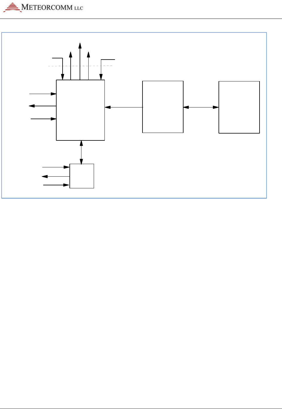
545C Operations Manual
02/10/2012 Prerelease DCN 00001789-A
© 2012 Meteorcomm LLC. All Rights Reserved. Proprietary and Confidential. Do Not Distribute. 99
Figure 16: Event programming block diagram
5.6.1 Event Programming Overview
Event programs are composed of signal test and action commands stored in
a non-volatile event table. The MCC-545A stores the event table in battery-
backed-up-RAM. The MCC-545B and MCC-545C store the event table in
FLASH memory.
The operator enters these event commands into the MCC-545C. The MCC-
545C scans the event table at power-up/reset, and then at every 1/16
second clock interval. It looks for the occurrence of defined events. When
a defined event occurs, the MCC-545C invokes the corresponding action
commands. The capability includes:
• Testing discrete input lines
• Setting or clearing a discrete output line
• Testing Analog input values
• Transmitting brief text messages
• Execute a local command of up to 40 characters
• Transmitting vehicle position reports
• Transmitting marker drop reports
MCC-545 Rf Modem EVENT SCRIPT
FILE TEXT EDITOR
XIO
$HT
TEXT
MESSAGES REMOTE
COMMANDS
DISCRETE
INPUTS
DISCRETE
OUTPUTS
ANALOG
INPUTS
DISCRETE
INPUTS
DISCRETE
OUTPUTS
ANALOG
INPUTS
RF LINK
SERIAL
PORT
MCLK
MDIR
MSET
POS TEXT
MSG
SDATA

545C Operations Manual
02/10/2012 Prerelease DCN 00001789-A
100 © 2012 Meteorcomm LLC. All Rights Reserved. Proprietary and Confidential. Do Not Distribute.
• Transmitting vehicle collision reports
• Transmitting canned message reports.
• Defining sensor data (SDATA) groups
• Transmitting sensor data (SDATA) reports
• Setting or clearing the MDP Status Bits
• Setting or clearing and testing 5 timers
• Testing GPS status as a discrete input
• Testing Network status as a discrete input
• Setting or clearing and testing counters
• Setting or clearing and testing 2 high-speed counters
• Outputting pulses and square waves (pulse modulation)
• Reading and counting pulse inputs
• Max, Min, Average or other real-time signal computations
The position, marker drop, collision and canned message reports created
conform to the FleetTrak standard. In addition other status bits can be set
or cleared individually. Up to 16 data report groups can be defined for
SDATA formatted data report generation.
The MCC-545C event monitor reads discrete and analog inputs and
evaluates them with respect to event definitions in the event table. It can
look for discrete input signals going persistently high or low, and for analog
signals persistently exceeding or under running thresholds.
5.6.2 Event Definition
An “event” occurs when some input signal or timer changes its state. You
can think of a state as being “on” or “off”, “1” or “0”, “true” or “false”.
When the state changes, an “action” can then be taken. Once the signal
has changed state and the action performed, it will not take further action
until the state changes again to prevent a continuous string of actions. For
example, if a switch is turned “on”, the lights come on and stay on. They
don’t continually go on,on,on… Once the switch is turned off, the lights
can go off, and then they are ready to be turned on again, etc.
There are three classes of events: Reset, Immediate and Scanned. Scanned
events subdivide into discrete I/O events and analog input events. These
are defined in the following paragraphs.

545C Operations Manual
02/10/2012 Prerelease DCN 00001789-A
© 2012 Meteorcomm LLC. All Rights Reserved. Proprietary and Confidential. Do Not Distribute. 101
Reset Event
A reset event occurs only once when the MCC-545C powered up or reset,
when the event monitor task is started for the first time, or is stopped -
then restarted. It is a well-defined event that does not need to scan
anything in order to determine whether or not a reset has occurred. It
occurs once on each power up or monitor-start. There is also no
corresponding end to this event. The logical end of this event would be
power failure or shutdown, but either such event makes the MCC-545C
unable to respond to anything. An action taken on a reset event command
will remain as defined in the command until the MCC-545C is reset again or
powered off, or until some other event changes the action. Stopping the
event monitor will not clear the reset event definitions.
Command Event
An immediate action can be triggered by entering a local event command
from any port, or by remote command sent over the RF link. This type of
action does not get stored in the event table and will not be re-issued on
power-up or restart. In this way, the operator has the ability to manually
override or control conditions in the field. The event state is considered to
be “true” as soon as the command is entered or received. Once the action
is completed, the event state is set to “false” again.
Scanned Event
Scanned events are tested on a periodic basis by the monitor task. An input
signal that would trigger a scanned event must be repeatedly tested to see
if the signal persists at a trigger level before an event is started. A scanned
event is started when a signal remains at (or above or below) the trigger
level for a defined settling duration. When an event is detected by its input
condition persisting at its high state for a settling duration, that event's
associated action is triggered and the monitor task begins looking for the
end of the event. The end of an event occurs when the event remains at a
low state for a defined hold-off duration. After the hold-off duration with
the input condition at its low state, the event is enabled to scan for the
next event.
For example, if an event is testing the battery voltage to be above 5.0
volts, the action will be triggered when the voltage is first detected to be
at or above 5.0 volts for the entire settling period. When the voltage goes
below 5.0 volts for the hold-off period, it will re-arm the event to trigger
the next time the voltage goes to or above 5.0 volts. The event action is

545C Operations Manual
02/10/2012 Prerelease DCN 00001789-A
102 © 2012 Meteorcomm LLC. All Rights Reserved. Proprietary and Confidential. Do Not Distribute.
not triggered when the voltage crosses the 5.0 level in the downward
direction, only the upward direction. If one wants to detect both voltage
crossings, there should be two events defined, one to detect the positive
change (ADCHI), and one to detect the negative change (ADCLOW).
The settling and hold-off durations are programmable for each scanned
event. They are specified in clock-tick counts where each tick is 62.5
milliseconds, or 1/16 second. Because these durations are programmable,
scanned event hysteresis is fully controllable. Given the 62.5 millisecond
sampling rate, events are limited to those that persist longer than 62.5
milliseconds but shorter than about an hour duration. Similarly, hold-off
times between events must also persist longer than 62.5 milliseconds.
Attempting to program events that are briefer than 62.5 milliseconds will
prove unreliable. It is important to remember that a scanned event must
change slow enough that the event monitor can sample the input line
reliably.
The external I/O expander (XIO) has its own processor to scan its event
definition table. Its internal “clock-tick” will be set to one millisecond per
increment. The MCC-545C will configure the XIO when event commands are
processed from the script file. The XIO will monitor its own events and send
changes to the MCC-545C using a serial interface.
Discrete Event
A discrete event is determined by whether or not a discrete input signal
remains either high or low for the given settling duration. “high” or “low”
is a part of the event definition set by the operator. The end of a discrete
event occurs when the signal has persistently returned to its previous low
or high state for the hold-off duration. For RS-232 signals, “high” is
considered the ON state and “low” the OFF state. “high” is also known as
SET; “low” as CLR.
The high/low convention follows the voltage level of the input signal. For
TTL signals, “high” is a +5 volt level, and “low” is zero volts. For the RS-
232 modem-control signals, “high” is +10 volts and “low” in -10 volts. For
the GPS input, a “high” is when the GPS is at “V1” or “V2” status, and
“low” is when there is no GPS characters being received at the RS-232 port
or when the GPS is at the “V0” status. The NET input is “high” when the RF
modem is online to a Base or Repeater that is connected to a host system.

545C Operations Manual
02/10/2012 Prerelease DCN 00001789-A
© 2012 Meteorcomm LLC. All Rights Reserved. Proprietary and Confidential. Do Not Distribute. 103
The NET “low” input indicates the RF modem is offline to a Base or
Repeater.
Analog Event
An analog event is determined by whether or not an analog input signal
remains above or below a threshold for the given settling duration.
“Above” or “below” and the threshold level are also given in the event
definition. The end of an analog event occurs when the signal has
persistently returned to the non-event side of the threshold for the hold-off
duration.
5.6.3 Action Definition
An “action” can be assigned to each event defined in the event table.
When the event condition is detected, the action is initiated. Available
actions are defined in the following sections. Multiple actions are
supported by defining multiple events that test the same input, but take
different action, or multiple actions can be defined using a special
“continue” event. The “continue” event does not test the input condition
again, but will trigger the action when the event it is connected to detects
the event.
Any action can be forced on a timed basis by several methods. One method
is to use the MCC-545C scheduler (SCHED command) to trigger the desired
immediate action. For example, the UPDT action can be specified by the
insertion of the EVENT,UPDT, group-number command into the MCC-545C
scheduler to produce reports on a timed basis. See the SCHED command for
this capability. Another example would be to pulse an output line by
placing two commands in the scheduled event list that would first SET then
CLR the signal. The duration of the pulse would be controlled by the offset
value in the SCHED command. Yet another method is to use an event timer
(counter) to facilitate scheduling of actions. Special timer registers are
provided for this purpose, and will automatically count down from a non-
zero value to zero at a rate of 1/16 seconds per count. An event command
can monitor the timer register, and when it reaches zero, the action can be
taken, and the timer reset to the next desired time count.
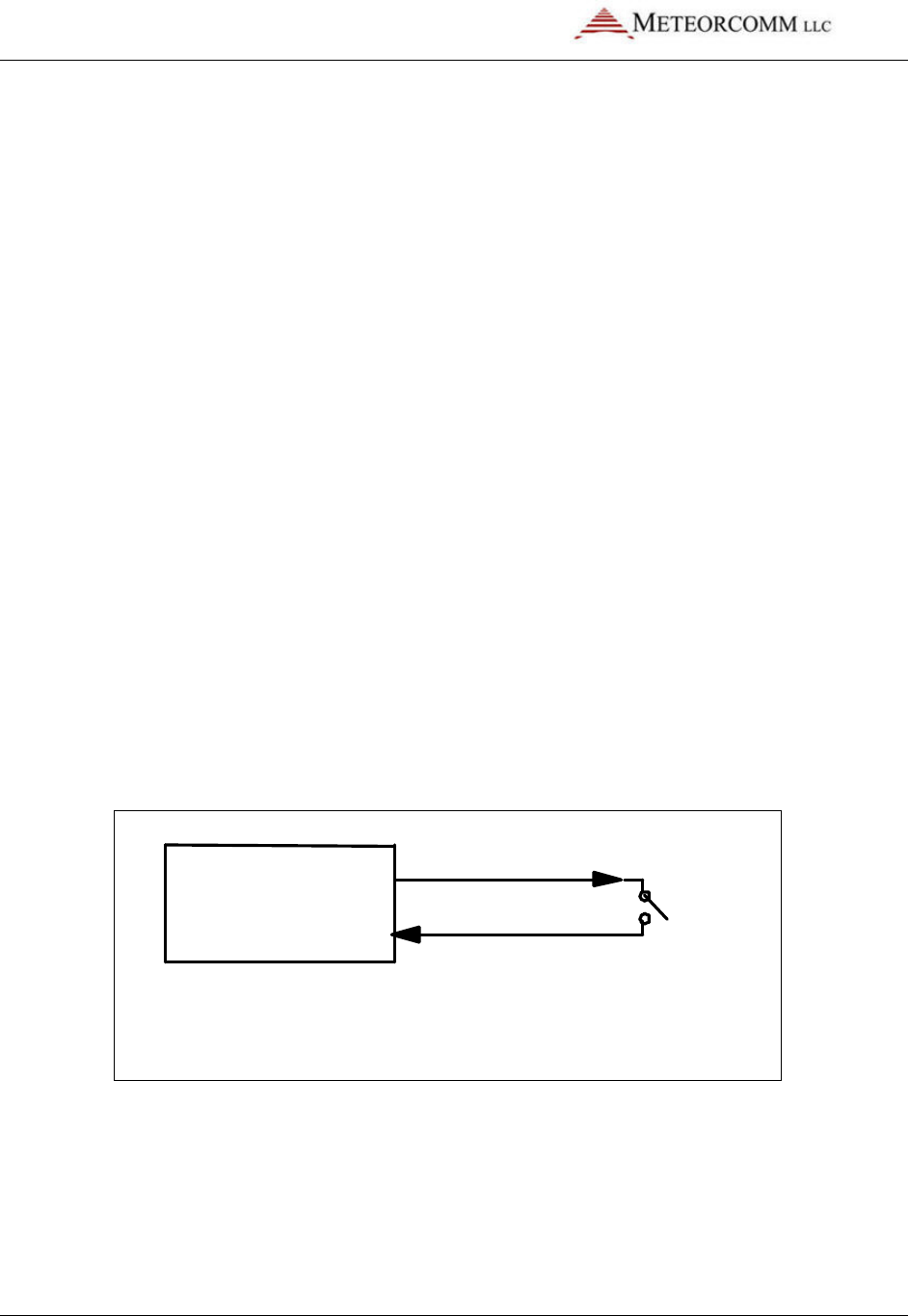
545C Operations Manual
02/10/2012 Prerelease DCN 00001789-A
104 © 2012 Meteorcomm LLC. All Rights Reserved. Proprietary and Confidential. Do Not Distribute.
5.6.4 Programming in Real-Time
Events are programmed via operator commands, one event per command
line. It is a multi-step process. Because of this, each event being entered
will be a fragment until all event definitions are complete. If the event
monitor is allowed to execute a fragment of an event, strange and possibly
adverse actions will occur. Therefore, the operator should stop the event
monitor when adding events and actions to the event table. The event
monitor task can be stopped and started by operator command. The best
way to do this is to use a script file containing the stop ;l,m command, a
command to delete all prior definitions, the desired event definitions, and
a start command.
Some examples are given below, following these, a detailed description of
each event command and action is given.
Example 1: A Scanned Event - Vehicle Tip-Over Detection
Suppose the MCC-545C is wired to detect a vehicle tip-over using the CTS
and DTR signals and a gravity switch that closes if it does not remain mostly
upright. The CTS output is used to enable tip-over detection. The DTR
input is the signal on which tip-over event is detected. Normally open, the
switch prevents DTR from receiving the CTS signal. If CTS is enabled and
the vehicle tips over such that the switch closes, the CTS signal is
presented to DTR.
MCC
-545 RF Modem
CTS
DTR
Gravity
Switch
CTS is set to 5V on power-up, DTR is low if switch is open
DTR will go high when the switch is closed
To make the tip-over detection mechanism function, the CTS signal must
be enabled so that it can be detected at DTR should the switch close. A
good time to enable CTS – set CTS to high – may be when the MCC-545C is
powered up. The command EVENT,RESET,SET,CTS will do this. The event is
RESET. The action is SET,CTS. The “ignition” bit should also be set in the
status word. The bits of the status register are numbered from low order to

545C Operations Manual
02/10/2012 Prerelease DCN 00001789-A
© 2012 Meteorcomm LLC. All Rights Reserved. Proprietary and Confidential. Do Not Distribute. 105
high order, BIT0 through BIT15. The COLLISION bit is the same as BIT0, and
the action “COLLISION” is used instead of “SET,BIT0” for clarity.
The command EVENT,DIOHI,DTR,16,160,COLLISION defines an event that
creates a vehicle collision report if the DTR signal is high for 1 second (16
sixteenths of a second). Collision is defined as the vehicle being tipped
over. The event will clear and be ready for another event if the signal is
low for 10 seconds (160 sixteenths of a second). DIOHI means “discrete I/O
high” and DTR specifies the DTR discrete input. The parameters
DIOHI,DTR,16,160 define the event. The parameter COLLISION defines the
action.
The User will create the event table with the following commands:
Example 2: A Scanned Event - Marker-Drop
Suppose the MCC-545C is wired to detect a marker-drop pushbutton using
the CTS and DTR signals wired to a pushbutton switch mounted somewhere
in a vehicle or aircraft. The CTS output is used to enable switch detection.
The DTR input is the input signal on which marker-drop is detected.
Normally open, the switch prevents DTR from receiving the CTS signal. If
CTS is enabled and the marker-drop button pressed such that the switch
closes, the CTS signal is presented to DTR.
MCC-545 RF Modem
CTS
DTR
Marker-Drop
Switch
CTS is set on reset in order to have a signal to detect on DTR
DTR is scanned every 1/16 second for the high condition
EVENT,STOP
EVENT,DEL,ALL
EVENT,RESET,SET,CTS
EVENT,RESET,SET,BIT2
EVENT,DIOHI,DTR,16,160,COLLISION
EVENT,START
SAVE

545C Operations Manual
02/10/2012 Prerelease DCN 00001789-A
106 © 2012 Meteorcomm LLC. All Rights Reserved. Proprietary and Confidential. Do Not Distribute.
To make the marker-drop mechanism function, the CTS signal must be
enabled so that it can be detected at DTR should the switch close. A good
time to enable CTS – set CTS to high – may be when the MCC-545C is
powered up. The command EVENT,RESET,SET,CTS will do this. The event
is RESET. The action is SET,CTS. The “ignition” bit should also be set in
the status word, the command EVENT,RESET,SET,BIT2 will set the ignition
bit. The bits of the status register are numbered from low order to high
order, BIT0 through BIT15. The MARK bit is the same as BIT3, and the
action MARK is used instead of SET,BIT3 for clarity.
The command EVENT,DIOHI,DTR,16,160,MARK defines an event that
creates a vehicle collision report if the DTR signal is high for 1 second (16
sixteenths of a second). The event will clear and be ready for another
event if the signal is low for 10 seconds (160 sixteenths of a second). DIOHI
means “discrete I/O high” and DTR specifies the DTR discrete input. The
parameters DIOHI,DTR,16,160 define the event. The parameter “MARK”
defines the action.
The User will create the event table with the following commands:
5.6.5 Event Programming Command Summary
There can be from 1 to 400 events defined in the event table including
reset and scanned events. The following list shows all the command
formats. Commands tagged “Yes” in the “Event” column each consume one
entry in the event table. Some of the commands, tagged with “No”, are
used to free up event table entries or control the operation of the event
monitor.
There is also a group table, and a text table. The group table is an array of
16 groups by 16 sensors. Each entry in the group table consists of a sensor
type – discrete or analog – and a discrete bit identification or analog
channel number. Commands tagged “Yes” in the “Group” column each
EVENT,STOP
EVENT,DEL,ALL
EVENT,RESET,SET,CTS
EVENT,RESET,SET,BIT2
EVENT,DIOHI,DTR,16,160,MARK
EVENT,START
SAVE

545C Operations Manual
02/10/2012 Prerelease DCN 00001789-A
© 2012 Meteorcomm LLC. All Rights Reserved. Proprietary and Confidential. Do Not Distribute. 107
consume one entry in the group table. Some of the commands with “Yes”
are used to free up group table entries. The text table is used to store up
to 40 text messages or operator commands of up to 40 characters each.
There are 8 accumulators, 8 timers and 8 counters that can be used to
facilitate the creation of complex logic.
Table Entry?
Command
Event Group
EVENT
No No
EVENT, DEL,
event number
No No
EVENT, DEL, ALL
No No
EVENT, START
No No
EVENT, STOP
No No
EVENT, RESET, action Yes No
EVENT, DIOHI, bit-name, settle, holdoff, action Yes No
EVENT, DIOLOW, bit-name, settle, holdoff, action Yes No
EVENT, ADCHI, chan-name, hi-level, settle, holdoff, action Yes No
EVENT, ADCLOW, chan-name, low-level, settle, holdoff, action Yes No
EVENT, IFGT,
bit
-
name, bit
-
name, action
Yes No
Table Entry?
Command
Event Group
EVENT, IFLT,
bit
-
name, bit
-
name, action
Yes No
EVENT, IFEQ,
bit
-
name, bit
-
name, action
Yes No
EVENT, CONT,
action
Yes No
EVENT, DO,
action
Yes No
EVENT, DISPLAY,
item
-
number
Yes No
EVENT, TEXT
No No
EVENT, TEXT,
item
-
number,
message text
Yes Yes
EVENT, TEXT, DEL, ALL
No No
EVENT, TEXT, DEL,
item
-
number
No No
EVENT, GROUP
No No
EVENT, GROUP, group-number, bit-name or chan-name, … No Yes
EVENT, GROUP, DEL, ALL
No Yes
EVENT, GROUP, CLEAR, group-number No Yes
EVENT, UPDT, group-number No No
EVENT, STATUS,
{
bit
-
name, chan
-
name
} No No
EVENT, action No No
SCALE, chan-name, slope, offset No No
5.6.6 Event Programming Command Details
Command: EVENT

545C Operations Manual
02/10/2012 Prerelease DCN 00001789-A
108 © 2012 Meteorcomm LLC. All Rights Reserved. Proprietary and Confidential. Do Not Distribute.
Displays the current event and group table when no additional parameters
are attached. All the event commands begin with “event,” followed by
parameters.
Command: EVENT, DEL, ALL
Delete all events in the event table. Event table commands should be
edited in script files and output to the MCC-545C using XTermW in order to
reload the event table. This command does not delete the text messages or
group definitions.
Command: EVENT, DEL, number
Delete only the numbered event from the event table. The events will be
renumbered when one is deleted. Event table commands should be edited
in script files and output to the MCC-545C using XTermW in order to reload
the event table.
Command: EVENT, START
Start the event scanner. Scanned events will not be detected unless
scanning is started. This command causes the event scanner to review the
event table every 62.5 milliseconds for the occurrence of scanned events
and the end of scanned events. This command also performs RESET events.
On MCC-545C reset, the event scanner is started.
Command: EVENT, STOP
Stop the event scanner. Scanned events will not be detected while
scanning is stopped. This command should be issued prior to clearing the
event table (EVENT,DEL,ALL) and reprogramming it with events. This
command does not affect the detection of the reset event. On MCC-545C
reset, the event scanner is started again if the SAVE command was not
issued while in the EVENT,STOP state.
Command: EVENT, action
A direct command for immediate action can be issued. This event
command will not be added to the event table, but will cause the action to
occur when the command is entered. This can be used to take action using

545C Operations Manual
02/10/2012 Prerelease DCN 00001789-A
© 2012 Meteorcomm LLC. All Rights Reserved. Proprietary and Confidential. Do Not Distribute. 109
remote commands, and also can be placed in the MCC-545C schedule list
for periodic event application.
Command: EVENT, STATUS, {bit-name, or chan-name}
This form of the command lets the operator display an immediate value for
any discrete input bit or any ADC channel. For example: to display the
status on the DTR input line, EVENT,STATUS,DTR<cr>. To display forward
power, enter EVENT,STATUS,FPWR<cr>.
Command: EVENT, RESET, action
Define an action to be taken at power-up/reset. This is useful for setting
control outputs at a known state or sending a message to a host system
that the MCC-545C has been reset. These RESET actions will also occur if
the event monitor is stopped, then restarted. This allows entering new
RESET events into an existing table.
Command: EVENT, DIOHI, bit-name, settle, holdoff, action
Define an event that looks for a discrete input line to go to a high level.
Parameter
Description
DIOHI
Scan discrete input signal for high condition.
bit-name
Name of discrete input signal to be scanned for high level. (single or multiple
inputs)
settle
Number of clock ticks for the input signal to settle at the high level before
declaring an event
holdoff
Number of clock ticks fo
r the analog input signal to settle at the low level to
be armed for detecting the next event.
action
MCC
-
545C action to be taken when event is declared. See actions below.
Logical combining of multiple discrete inputs is allowed. This is done by
expanding the bit-name parameter of the command into a list on inputs
separated by logic operator characters. For example, to test both the RTS
and DTR inputs in one event, use the string “,DTR & RTS,” in the bit-name
parameter. Up to 5 inputs can be used in a single event line. Any of the
inputs can be “inverted” before the combination. For example, if the DTR
input must be high and the RTS input low to trigger an event, use the string
“,DTR & !RTS,” in the bit-name parameter.

545C Operations Manual
02/10/2012 Prerelease DCN 00001789-A
110 © 2012 Meteorcomm LLC. All Rights Reserved. Proprietary and Confidential. Do Not Distribute.
The inputs can be combined in any order. The evaluation is done from left
to right. There is no use of “(“ and “)” to form more complex ordering. The
“0” and “1” values are used for “low’ and “high”. If the result of the
combination of signals is “1”, then the DIOHI condition is satisfied. If the
result of the combination is “0”, then the DIOLOW condition is satisfied.
Both the DIOHI and DIOLOW event types can use the logical signal support.
Table of Logical Operators:
Operator
Definition
&
AND
|
OR
!
NOT
Logical
signal inversion
Command: EVENT, DIOLOW, bit-name, settle, holdoff, action
Define an event that looks for a discrete input line to go to a low level.
Parameter
Description
DIOLOW
Scan discrete input signal for low condition.
bit-name
Name of discrete input signal to be scanned for low level. (single or multiple
inputs)
settle
Number of clock ticks for the input signal to settle at the low level before
declaring an event.
holdoff
Number of clock ticks for the analog input signal t
o settle at the high level to
be armed for detecting the next event.
action
MCC
-
545C action to be taken when event is declared. See actions below.
Command: EVENT, IFGT, bit-name1, bit-name2, action
Test whether a timer, counter or accumulator is greater than another
timer, counter or accumulator.
Parameter Description
IFGT
If first parameter is greater than second parameter.
bit-name1
Name of a timer, counter or accumulator to test.
bit-name2
Name of a
timer, counter or accumulator to test bit
-
name1 against.
Action
MCC
-
545C action to be taken when event is declared
.
See actions below.
Command: EVENT, IFLT, bit-name1, bit-name2, action
Test whether a timer, counter or accumulator is less than another timer,
counter or accumulator.

545C Operations Manual
02/10/2012 Prerelease DCN 00001789-A
© 2012 Meteorcomm LLC. All Rights Reserved. Proprietary and Confidential. Do Not Distribute. 111
Parameter Description
IFGT
If first parameter is less than second parameter.
bit-name1
Name of a timer, counter or accumulator to test.
bit-name2
Name of a timer, counter or accumulator to test bit
-
name1 against.
Action
MCC
-
545C action to be taken when event is declared. See actions
below.
Command: EVENT, IFEQ, bit-name1, bit-name2, action
Test whether a timer, counter or accumulator is equal to another timer,
counter or accumulator.
Parameter Description
IFEQ
If first parameter is equal to second parameter.
bit-name1
Name of a timer, counter or accumulator to test.
bit-name2
Name of a timer, counter or accumulator to test bit
-
name1 against.
Action
MCC
-
545C action to be taken when event is declared. See
actions
below.
Command: EVENT, CONT, action
The CONT (Continue) event is used to define multiple actions to an event.
An event definition command can be followed by any number of CONT
commands and are considered to be an extension of the previous event
command. For example:
EVENT,DIOHI,DTR,1,1,SET,BIT0 ;Defines an event with one action
EVENT,CONT,TXT,1 ;Add another action
EVENT,CONT,UPDT,1 ;Add another action
EVENT,CONT,CLR,T1 ;Add another action
EVENT,DIOLOW,DTR,1,1,CLR,BIT0 ;End previous event definition, Start next one
Command: EVENT, DO, action
The DO event is provided for cases where an unconditional action is
required. This type of event is not connected to other event lines as the
CONT is. It is independent and will be initiated every time the event
monitor executes the script item. For example: EVENT,DO,INC,C1
Command: EVENT, ADCHI, chan-name, hi-level, settle, holdoff,
action

545C Operations Manual
02/10/2012 Prerelease DCN 00001789-A
112 © 2012 Meteorcomm LLC. All Rights Reserved. Proprietary and Confidential. Do Not Distribute.
Define an event that looks for an analog input signal to go at or above a
high level.
Parameter
Description
ADCHI
Scan A-to-D converter channel (analog input signal) for high condition.
chan-
name
Name of analog input signal to be scanned for high condition. (single input
only)
hi-level
Signal level for the event to trigger at or above which the analog input
signal
must persist in order for an event to be declared. Scaled in Engineering
Units.
settle
Number of clock ticks for the input signal to settle at or above the trigger
level before declaring an event.
holdoff
Number of clock ticks for the input signal to settle below the trigger level to
be armed for detecting the next event.
action
MCC
-
545C action to be taken when event is declared. See actions below.
Command: EVENT, ADCLOW, chan-name, low-level, settle, holdoff, action
Define an event that looks for an analog input signal to go at or below a
low level.
Parameter
Description
ADCLOW
Scan A-to-D converter channel (analog input signal) for low condition.
chan-
name
Name of analog input signal to be scanned
for low condition (single input
only).
low-level
Signal level for the event to trigger at or below which the analog input signal
must persist in order for an event to be declared. Scaled in Engineering
Units.
settle
Number of clock ticks for the input
signal to settle at or below the trigger
level before declaring an event.
holdoff
Number of clock ticks for the input signal to settle above the trigger level to
be armed for detecting the next event.
action
MCC
-
545C action to be taken when event is d
eclared. See actions below.
Command: EVENT, TEXT, item-number, message or command text
Add a new text string into the text table. This command will replace an
existing item if one already exists with the same item number.

545C Operations Manual
02/10/2012 Prerelease DCN 00001789-A
© 2012 Meteorcomm LLC. All Rights Reserved. Proprietary and Confidential. Do Not Distribute. 113
Parameter Description
TEXT
Define a Text string command.
item-
number
Item number to be created or replaced by this command. Valid range: 1
through 40.
message
text
Body of the text. Can be up to 40 characters, and will be converted to upper
case. The text is used by the TXT or CMD action to send a text message or
issue a local command.
Command: EVENT, TEXT
Displays the current text table.
Command: EVENT, TEXT, DEL, ALL
Deletes all previously defined text items.
Command: EVENT, TEXT, DEL, item-number
Deletes a specific item from the text table. This command makes the given
item be a null message. The other text string items in the table are not
affected.
Command: EVENT, GROUP
Displays the group table. There can be as many as 16 groups defined,
where each group consists of a selected set of analog inputs or discrete
inputs. The “event, group” set of commands allows the groups to be
defined, displayed, and transmitted as a sensor data report.
The Group Table layout is like a two dimensional array where each row is a
different group, and each column is a different sensor. In this case a sensor
can be either an analog or discrete input. “type” indicates discrete or
analog. For discrete, “id” is the bit number. For analog, “id”is the channel
number.
Sensor Number
1 2 3 ● ● ●
16
Group Number
1
type/id type/id type/id
type/id
2
type/id type/id type/id
type/id
3
type/id type/id type/id
type/id
●
●
●

545C Operations Manual
02/10/2012 Prerelease DCN 00001789-A
114 © 2012 Meteorcomm LLC. All Rights Reserved. Proprietary and Confidential. Do Not Distribute.
16
type/id type/id type/id
type/id
Command: EVENT, GROUP, group-number, bit-name or chan-name, ...
Define an event sensor data (SDATA) report group.
Parameter Description
GROUP
Group control event command.
group-
number
bit-name or
chan-name
Group number to be set by this command. Valid range: 1 through 16.
List of up to 16 discrete and/or analog input signal names to be included in
the group. The values of these signals form the contents of a sensor data
(SDATA) report. They are reported in the order specified in this command.
Append a “/F” to any name for floating point scaling. Append “(x.xx)” for
decimal scaling as: ADC1/F(0.1)
Example: EVENT, GROUP, 1, FPWR/F, ADC1, ADC2/F(1.123)
Command: EVENT, GROUP, DEL, ALL
Delete all group definitions. Clears the group table.
Command: EVENT, GROUP, DEL, group-number
Delete a specific group definition from the group table. This does not cause
the other defined groups to be renumbered.
Parameter Description
GROUP
Group control event command.
DEL
Delete group table sub-command.
group-
number
Group number to be deleted by this command. Valid range: 1 through 16.
Command: EVENT, UPDT, group-number
Produce an immediate SDATA group report when the command is entered.
Parameter Description
UPDT
Update sub-command; i.e., issue a group sensor data (SDATA) report.
group-
number
Group number to be reported in an SDATA report. Valid range: 1 through 16.

545C Operations Manual
02/10/2012 Prerelease DCN 00001789-A
© 2012 Meteorcomm LLC. All Rights Reserved. Proprietary and Confidential. Do Not Distribute. 115
This command can be included in the MCC-545C schedule to produce
reports on a periodic or prescribed time of day. For example,
SCHED,I,10:0,EVENT,UPDT,3 will schedule the group 3 sensor data report
every 10 minutes.
Command: SCALE, chan-name, slope {, offset}
Enter engineering units scale factor and offset for an analog channel. This
adds the optional offset parameter to the original MCC-545C SCALE
command. Analog event detection is based on scaled values, not raw
counts. The scaled value is computed as:
scaled value = (analog channel raw count * slope) + offset
Parameter Description
chan-name
Name of analog input channel to be scaled by the factors
provided in this
command.
slope
Multiplier scaling factor. The analog input channel raw count is
multiplied by this value. Valid: any decimal floating point number that
can be represented in Motorola 68000 32-bit floating point format.
However, there is a further restriction on the value of slope. See below.

545C Operations Manual
02/10/2012 Prerelease DCN 00001789-A
116 © 2012 Meteorcomm LLC. All Rights Reserved. Proprietary and Confidential. Do Not Distribute.
Parameter Description
offset
Bias scaling factor. This value is added to the product of the channel raw
count and the multiplier scaling factor. Optional parameter. Assumes
zero offset when not given. Valid: any decimal floating point number
that can be represented in Motorola 68000 32-bit floating point format.
However, there is a further restriction on the value of slope. See below.
Slope and offset values must be chosen such that the resultant scaled value
is in the range -8192.0 through -0.001, 0.000 and +0.001 through +8191.0.
Only four digits of the scaled value are significant.
5.6.7 Action Details
The following table shows the possible types of action that can be taken
when an event occurs.
Action Value Action Parameters Description
TXT
, nn
text table item number
Transmit a text message to the default destinations
.
“nn” can range from 1 to 40.
CMD
, nn
text table item number
Execute a local command
.
“nn”can range from 1 to 40.
CAN,
nn
canned message number
The canned
message number is transmitted to 1 to 4
default destination IDs. “nn”can range from 0 to 255.
POS
A position report with current GPS coordinates is
transmitted to 1 to 4 default destination IDs.
MARK
A marker report with current GPS coordinates is
transmitted to 1 to 4 default destination IDs. The
marker bit is set in one report, but does not remain
set.
COLLISION
A vehicle collision report is transmitted to 1 to 4
default destination IDs. The collision bit is set in one
report, but does not remain set.
SET, ccc,
ddd
ccc=Bit, Timer, Counter,
Accumulator Name
ddd=optional decimal
value for Timer, Counter
or Accumulator
If “ccc” is a named discrete output or status bit, it is
set = 1 and “ddd” is not used. If “ccc” is a Timer,
Counter or Accumulator, then “ddd” is a decimal value
to put into “ccc”. If “ccc” is a status bit, a POSS report
will be transmitted with the updated status bits. The
bit remains set.
SET/N, ccc
ccc = status bit name
Sets the status bit and does
not
transmit POSS
SET/T, ccc
ccc = status bit name
Trigger a POSS report after setting the status bit, but
clear the bit after the transmission so it is a one-time
event and does not persist.
CLR, ccc
ccc=Bit, Timer, Counter,
Accumulator Name
The named discrete output,
status bit, Timer, Counter
or Accumulator is cleared to 0. If “ccc” is a status bit,
a POSS report will be transmitted with the updated

545C Operations Manual
02/10/2012 Prerelease DCN 00001789-A
© 2012 Meteorcomm LLC. All Rights Reserved. Proprietary and Confidential. Do Not Distribute. 117
Action Value Action Parameters Description
status bits
.
The bit remains cleared.
CLR/N,ccc
ccc = status bit name
Clears the status bit and does
not
transmit POSS.
PULSE,bit-
name, ddd,
iii, nnn
bit-name = any discrete
output signal
ddd = pulse duration
iii = interval between
pulses
nnn = number of pulses
Produce a pulse or series of pulses on the output line
where:“ddd” is the pulse duration in clock ticks, “iii”
is the interval between pulses in clock ticks, and “nnn”
is the number of pulses to output.
ADCIN, ccc,
aaa, mult
ccc=any ADC channel
name
aaa=accumulator name
A1 – A24
mult=decimal scaling
multiplier
Read the ADC channel value and store in it the given
accumulator. The value is scaled, multiplied by the
optional multiplier, then converted from floating point
to a long 32-bit integer. The value of 10.123 with a
multiplier of 10 will be stored as 103.
UPDT,
group-
number
SDATA report group
number
The SDATA
report specified by the group number is
transmitted to 1 to 4 default destination ids.
NC, ccc
+1
Increment a counter by 1
.
“ccc” must be a valid
counter (C1-C8)
DEC, ccc
-1
Decrement a counter by 1
.
“ccc” must be a valid
counter (C1-C8)
ADD, ccc,
ddd
Add the decimal value of “ddd” to “ccc”
.
“ccc” must
be a valid accumulator (A1-A24). The result is stored in
“ccc”.
SUB, ccc,
ddd
Subtract the decimal value of “ddd” from “ccc”
.
“ccc”
must be a valid accumulator (A1-A24). The result is
stored in “ccc”.
MUL, ccc,
ddd
Multiply “ccc” by the decimal value of “ddd” and place
the result in “ccc”. “ccc” must be a valid accumulator
(A1-A24).
DIV, ccc,
ddd
Divide “ccc” by the decimal value of “ddd” and place
the result in “ccc”. “ccc” must be a valid accumulator
(A1-A24).
MOV, ddd,
sss
Move the source “sss” into “ddd”
.
“sss” and “ddd” are
valid Timers (T1-T8) , Counters (C1-C8) or
Accumulators (A1-A24).
ADDA, ccc,
aaa
Add the accumulator value of “aaa” to “ccc”
.
“aaa”
and “ccc” must be a valid accumulator (A1-A24) . The
result is stored in “ccc”.
SUBA, ccc,
aaa
Subtract the accumulator value of “aaa” from “ccc”
.
“aaa” and “ccc” must be a valid accumulator (A1-A24)
. The result is stored in “ccc”.
MULA, ccc,
aaa
Multiply “
ccc” by the accumulator value of “aaa” and
place the result in “ccc”. “aaa” and “ccc” must be a
valid accumulator (A1-A24).

545C Operations Manual
02/10/2012 Prerelease DCN 00001789-A
118 © 2012 Meteorcomm LLC. All Rights Reserved. Proprietary and Confidential. Do Not Distribute.
Action Value Action Parameters Description
DIVA, ccc,
aaa
Divide “ccc” by the accumulator value of “aaa” and
place the result in “ccc”. Where “aaa” and “ccc”
accumulator (A1-A24).
The default destination IDs for messages created by the actions above are
set via the DESTINATION, d1 {, d2 {, d3 {, d4}}} command. When a single ID
of “0” is given in a Meteor Burst network that uses the MCC-520B for a
Master Station, the messages are sent to the network host system for
routing via the source routing system. In a Line-of-Sight network, using
MCC-545Cs as Base and/or Repeater Stations, then a single ID of “1” is used
for routing to the Host via any Base or Repeater.
5.6.8 Reading Internal Sensor Values
The MCC-545C -03 and later radios have the capability to read certain
sensor values, including the internal rechargeable battery, internal
temperature of the unit, etc.
Following are the most commonly used commands to read these sensor
values:
Command Description
EVENT,STATUS,TEMP
Reads the internal temperature of the unit
EVENT,STATUS,BAT
Reads the unloaded battery (external) of the radio
EVENT,STATUS,LBAT
Reads the loaded battery (external) of the radio
EVENT,STATUS,IBAT
Reads internal NiMetal Hydride rechargeable battery
EVENT,STATUS,ADC1
(through ADC6)
5.6.9 Common Command Parameters
a. settle
settle is the number of clock ticks required “at or above” the event level
to trigger an event. Valid range: 1 - 65535. This corresponds to a range of
62.5 milliseconds to 1 hour, 8 minutes and 16 seconds. For discrete events,
the event level is “high” or “1”. For analog events, the level is given in
engineering units.

545C Operations Manual
02/10/2012 Prerelease DCN 00001789-A
© 2012 Meteorcomm LLC. All Rights Reserved. Proprietary and Confidential. Do Not Distribute. 119
b. holdoff
holdoff is the number of clock ticks required “below” the event level to
allow another event. Valid range: 1 - 65535. This corresponds to a range of
62.5 milliseconds to 1 hour, 8 minutes and 16 seconds.
c. bit-name
Bit Name I/O; Voltage Range Definition Description
BIT0-
BIT15
Status Register Bits
0 or
1
The bit names BIT0, BIT1, …through BIT15
correspond to the bits of the 16-bit status register.
BIT0 is the low order bit, BIT15 is the high order bit.
DTR
Input; TTL 0V to 5V
Data
Terminal
Ready
RS
-
232 serial port signal indicating the data terminal
connected to the serial port is ready and able to
receive data from the MCC-545C (dataset) on Rx
Data.
RTS
Input; RS 232 ±10V
Request
to Send
RS
-
232 serial port signal indicating the data terminal
connected to the serial port wants to transmit data
to the MCC-545C (dataset) on Tx Data.
CTS
Output; TTL 0V to 5V
Clear to
Send
RS
-
232 serial port signal indicating the MCC
-
545C
(dataset) is ready and able to receive data from the
data terminal connected to the serial port on Tx
Data.
RING
Output; RS-232 ±10V
Ring
Detected
RS
-
232 serial port signal indicating the MCC
-
545C
(dataset) is wants the attention of the data terminal
connected to the serial port.
MCLK
Output; TTL 0V to 5V
Clock
These three signals can be used as individual inputs
and outputs as noted. In addition they can be used to
communicate with the external I/O expander using a
clocked serial high speed data stream.
MDIR
Output; TTL 0V to 5V
Data In
MSET
Input; TTL 0V to 5V
Data Out
IN1,IN2
IN3,IN4
Optically Isolated
Inputs 0-5 Volts
0 or 1
Typically requires an input greater than 1 volt to
trigger an input transition from 0 to 1.
RO1,RO2
Relay Contacts
NO,NC
Provides NO,COM,NC contacts
GPS
GPS status
0 or 1
Current GPS receiver status and RS
-
232 port
condition. 0=V0 or RS-232 disconnected. 1=V1 or V2
and RS-232 connected.
NET
Network Status
0 or 1
Network online/offline status
.
0=offline , 1=online
T1 – T8
32-bit Timers can be
used both as an Input
and as an Output.
Timers range from 0
to 16,777,216 counts.
(12 days, 2 hrs, 18
min, 58.5 seconds)
0 or n
Timer registers
.
When these are set to a non
-
zero
value, they will count down one count for each 1/16
second (62.5 milliseconds).
Use action = SET, T1, nnnn to start counting. These
all are set=0 on reset. Power fail/restart will retain
the count at power fail.

545C Operations Manual
02/10/2012 Prerelease DCN 00001789-A
120 © 2012 Meteorcomm LLC. All Rights Reserved. Proprietary and Confidential. Do Not Distribute.
Bit Name I/O; Voltage Range Definition Description
C1 – C8
32-bit Counters can
be used both as an
input and as an
output. Counters can
range from 0 to
16,777,216 counts.
0 or n
Counter registers
.
These can be set to a value,
cleared to zero, incremented or decremented. A 0
decrements to 16,777,216. A 16,777,216 increments
to 0.
A1-A24
32-bit Accumulators
can be used both as
an input and as an
output. Value can
range from 0 to +/-
16,777,216
0 or n
General purpose accumulators
.
These are used for
computational or temporary storage of numerical
values.
Each of the bit-names in the above table can be used in Event and Action
definitions. The DIOHI/DIOLOW events can use DTR, RTS, IN1-4, GPS, NET,
T1-T8, C1-C8, A1-A24 as inputs. The Action parameter can use BIT0-BIT15,
CTS, RING, MCLK, MDIR, MSET, RO1-R02, T1-T8, C1-C8, A1-A24 as outputs.
Examples:
EVENT,DIOHI,IN1,16,16,SET,RO1 Waits for input line 1 to go high for 1
second, then sets RO1 to NC.
EVENT,DIOLOW,DTR,16,16,SET,T1,160 Waits for DTR to go high for 1
second, then starts timer-1 at 160 counts (10 seconds).
EVENT,DIOLOW,T1,1,1,TXT,1 Waits for timer-1 to go to
zero, then sends a text message indicating that DTR timed-out.
5.6.10 ADC Channel Names
Channel
Name
Definition Description
FPWR
Forward RF
power
RF power going out of the MCC
-
545C transmitter.
RPWR
Reverse RF
power
RF power being reflected back to the MCC
-
545C
transmitter.
LBAT
Battery level
Voltage level of the MCC
-
545C battery.
DETRF
Detected RF
Current
MCC
-
545C receiver detected RF level.
TEMP
Internal
temperature
Internal temperature of the MCC
-
545C enclosure.
TXC
Transmit Count
Total number of transmissions
ACK
Acknowledge
Count
Total number of acknowledgements

545C Operations Manual
02/10/2012 Prerelease DCN 00001789-A
© 2012 Meteorcomm LLC. All Rights Reserved. Proprietary and Confidential. Do Not Distribute. 121
Channel
Name
Definition Description
RXC
Received
Segments
Total number of
received text message segments,
position reports and data reports
PROBE
Idle Probe Count
Total number of Idle probes and poll frames received
REMOTE
Number of
Remotes
Number of remotes connected to this unit.
ADC1
Analog Input
Available MCC
-
545C
10
-
bit A
-
to
-
D channel.
ADC2
Analog Input
Available MCC
-
545C 10
-
bit A
-
to
-
D channel.
ADC3
Analog Input
Available MCC
-
545C 10
-
bit A
-
to
-
D channel.
ADC4
Analog Input
Available MCC
-
545C 10
-
bit A
-
to
-
D channel.
ADC5
Analog Input
Available MCC
-
545C 10
-
bit
A
-
to
-
D channel.
ADC6
Analog Input
Available MCC
-
545C 10
-
bit A
-
to
-
D channel.
5.7 Command Summary
Table 7: MCC-545C commands
All implemented 545C commands are listed in Table 4.2 alphabetically for ease of
reference. However, many commands are used in conjunction with others. These
functional groups are given below. You may also type HELP or HELP,command to
receive an explanation of any listed command. Command responses and unsolicited
printouts are shown in Appendix A.
STATION CONFIGURATION COMMANDS
STATUS COMMANDS
MESSAGE
COMMANDS
†*ASSIGN
†RCT
BINS
CANMSG
*BRATE
†REMOTE TYPE
CLS
CANMSG MODE
*CHECKIN
†RXTYPE
CONFIG
CANMSG OFF
†CLOSE PORT
SAVE
*HOURLIES
†COMPRESSION
†CONNECT
†SCALE
MEM
DEL MSG
DATE
†SCHED
MODE
DQE RXQ
*DESTINATION
SERIAL
†MON
DQE TXQ
*DEVICE
*SET BAUD
†MONOFF
FLUSH MSG
*DUTY CYCLE
†*SNP
†NETMON
FLUSH RXQ
*FREQUENCIES
*SOURCE RELAY
STAT
FLUSH TXQ
†HOST MODE
†START
*STAT TIME
*HOLD
†*ID
†STOP
T
MESSAGE

545C Operations Manual
02/10/2012 Prerelease DCN 00001789-A
122 © 2012 Meteorcomm LLC. All Rights Reserved. Proprietary and Confidential. Do Not Distribute.
†LOGOFF
†STT
TEST
*MSG
†LOGON
†SUBST
*PRINT
*LOS CHECKIN
*SYNTH
REMCMD
*MODULATION
TIME
†NEW PASSWORD
†TIME ZONE
POSITION LOCATION COMMANDS
†OPEN PORT
*TXLIMIT
†*POS
†RED
†PASSWORDMOD
E
†POSRPT
†RTCM
MODE CONTROL COMMANDS
MASTER SIMULATOR COMMANDS
†CORPAT
†*HALF DUPLEX
*P
*FULL DUPLEX
†*ROLE
MAINTENANCE COMMANDS
DUAL MASTER STATION COMMANDS
BOOT
SHOW TXQ
†SWCTL
SWMON
RESET
SMS
REV
UPDT
UTILITY COMMANDS
SHOW RXQ
FLASH
HELP
WARNING/WEATHER SYSTEM
COMMANDS
DATA LOGGER COMMANDS
†FLOOD
TIMEOUT
†SENSOR
P77
SDATA
†GLOF
†STATION TYPE
†$PENTM
†GLOF MONITOR
†WARNING
†HORN
†WARNING TIMEOUT
†PRIORITY
†WEATHER
CR10X COMMANDS
CR10X
CR10X,ORDER
CR10X,SETPTR
†CR10X,ACQMODE
CR10X,REGISTER
CR10X,SIGNATURE
†CR10X,GROUP
CR10X,RESET
CR10X,STAT
†CR10X,INTERVAL
†CR10X,SCALE
†CR10X,TIME

545C Operations Manual
02/10/2012 Prerelease DCN 00001789-A
© 2012 Meteorcomm LLC. All Rights Reserved. Proprietary and Confidential. Do Not Distribute. 123
CR10X,MAXQ
CR10X,SECURITY
CR10X,UPLOAD
MASTER MODE COMMANDS
*BASE
NET STAT
SHOW MAINTENANCE
MONITOR
CLEAR MAINTENANCE
MONITOR
NET STAT PERIOD
SHOW REMOTES
CONFIGURATION
†POLL
SHOW RXQ
LISTM
PRG
SHOW TXQ
LISTT
REMOTE
STAT
SML
MM
*REPEATER
SMS
NET
RX STAT
TYPE
* Parameters/settings specified by these commands are stored in Parameter Memory (CPM). Changes
specified by these commands take effect immediately but are lost when the unit is rebooted unless the
SAVE command is issued to write the changes to the non-volatile Flash memory. Changing the unit ID
automatically saves the entire configuration.
† Parameters/settings specified by these commands are stored in battery backed-up Data Memory
(RAM). Changes specified by these commands take effect immediately but are lost when the unit is
rebooted unless the SAVE command is issued to write the changes to RAM; in addition, the connector
J1 must be in place to enable RAM back-up.
If both symbols are present on a command, certain aspects are stored in one way and other aspects are
stored in the other. See command table below for clarifications.

545C Operations Manual
02/10/2012 Prerelease DCN 00001789-A
124 © 2012 Meteorcomm LLC. All Rights Reserved. Proprietary and Confidential. Do Not Distribute.
Table 7: MCC-545C commands (continued)
COMMAND DESCRIPTION PARAMETERS RANGE

545C Operations Manual
02/10/2012 Prerelease DCN 00001789-A
© 2012 Meteorcomm LLC. All Rights Reserved. Proprietary and Confidential. Do Not Distribute. 125
COMMAND DESCRIPTION PARAMETERS RANGE
†*ASSIGN
{,function,port,protocol
{,timeout}}
NOTE
function, port and protocol
information for ports 0, 1, 2
are stored in CPM; this
information for port 3 and all
timeout information is stored
in BBU RAM.
Control allocation of user interface functions
among physical device channels. When no
parameters are entered, displays I/O
configurations. Port definitions are as follows:
Front Panel
Port Connector
0 OPERATOR PORT
DATA PORT
2 AUXILIARY PORT
3 DIAGNOSTICS PORT
(Internal)
NOTE
It is possible to “lose control” of the 545C
software by assigning control functions to ports
with no devices attached or by turning off
control functions. For example, if you turn off
the Operator Port (ASSIGN,MNT,OFF), you will
not be able to enter commands or view
printouts from the 545C. You must open the
545C and press the Reset button on the
microprocessor board to re-enable the Operator
Port.
function = user interface
function
port = physical device
channel
protocol = link level
protocol
timeout in seconds
MNT, DTA, ALT,
POS
0-2, OFF
ASCII,F
WS,GPS,IHS,MSC,P
HAROS,IDA,PKT,D
ATALITE, AEI
RTCM,APCL5,CR10
X,ENAV,TRAN,GYR
O,H350,DIRECT,
UAIS,
PAKBUS,SERPT,CR
10XTD,DG1100,GE
NERIC,
SOUNDER
0 – 32767

545C Operations Manual
02/10/2012 Prerelease DCN 00001789-A
126 © 2012 Meteorcomm LLC. All Rights Reserved. Proprietary and Confidential. Do Not Distribute.
COMMAND DESCRIPTION PARAMETERS RANGE
AIS Display AIS Data
AIS, INT, n Set static data Tx interval (Minutes)
AIS, DSINT, n Set depth sounder Tx interval (Seconds)
AIS, DEL, ALL Delete previous pre-set static data
AIS,
ADD,ID,TYPE,NAME,MMSI,C
ALL,IMO,DRAUGHT,A,B,C,D,
DESTINATION
AIS, MMSI, nnnnnnnnn 9-digit MSSI number
AIS, IMO, nnnnnnnnn 9-digit IMO number
AIS, NAME,
cccccccccccccccccccc
20-char Name
AIS, CALL, ccccccc 7-char call sign
AIS, TYPE, nn 2-digit vessel type (see ITU)
AIS, ANT,A,B,C,D Ship/Antenna Dimensions in meters 0-25.5
AIS, DRAUGHT, nn.n Ships draught in meters

545C Operations Manual
02/10/2012 Prerelease DCN 00001789-A
© 2012 Meteorcomm LLC. All Rights Reserved. Proprietary and Confidential. Do Not Distribute. 127
COMMAND DESCRIPTION PARAMETERS RANGE
AIS, PERSONS, nnnn Number of persons on board 0-8191
AIS, TIME, HH:MM:SS ETA time
AIS, DATE, MM/DD/YY ETA date
AIS, DEST,
dddddddddddddddddddd
20-char Destination
AIS, NAV STAT, n Navigation status code 0-9 (see ITU)
*BASE{,nnn,nnn} Set/display range of Master Station IDs reserved
for use as Base Stations.
nnn = Master Station ID
OFF = no Bases
2 – 253
BINS Print link distribution statistics
BOOT Cold start of Station software. All volatile
memory is lost.
*BRATE,rate Reports transmit bit rate in kilobits per second.
This is fixed at 9.6 kbps
rate = 9.6K

545C Operations Manual
02/10/2012 Prerelease DCN 00001789-A
128 © 2012 Meteorcomm LLC. All Rights Reserved. Proprietary and Confidential. Do Not Distribute.
COMMAND DESCRIPTION PARAMETERS RANGE
CANMSG,nnnn (,msg length
{,min queue depth},{total})
Automatically generate a message of specified
length that repeats until turned off with
CANMSG OFF command. You can compose the
message by entering only the destination name
(not message length or minimum queue depth).
Destination node must be a neighbor node.
CANMSG cannot contain more than 25 messages
in its queue. If the number of canned message in
queue falls below minimum queue depth,
additional canned messages will be injected.
nnnn = Station ID
Master = 1 – 4095
Remote = 256 – 4095
msg length = number of
characters in message
min queue depth = min. # of
canned messages in queue
total = total number of
canned messages to
generate
1 – 4095
1 – 3000
0 – 25
0 – 9999
CANMSG MODE {,mode) Set reception of canned message to two of the
following states:
PRINT – print all messages
NO PRINT – does not print messages
mode = PRINT
NO PRINT

545C Operations Manual
02/10/2012 Prerelease DCN 00001789-A
© 2012 Meteorcomm LLC. All Rights Reserved. Proprietary and Confidential. Do Not Distribute. 129
COMMAND DESCRIPTION PARAMETERS RANGE
CANMSG OFF,nnnn Turn canned message mode off nnnn = Station ID
Master = 1 – 245
Remote = 256 - 4095
1 – 4095
*CHECKIN{,ii} Select check-in interval in seconds ii = interval 1 – 65535
CLEARBINS Clear hourly bins
CLEARLINKSTAT Clear link stats
†CLOSE PORT,function
{,function,…}
Close specified 545C port from operation. You
can enter more than one port name to close,
using commas to separate the names on the
same line.
CAUTION
The OPEN/CLOSE PORT commands directly
affect 545C network activity and message flow.
Do NOT use these commands unless directed to
do so.
function = user interface
function
MNT, POS,
MSG, ALT, DTA,
C&S
CLS Print current values, then clear link statistics (see
LINKSTAT).

545C Operations Manual
02/10/2012 Prerelease DCN 00001789-A
130 © 2012 Meteorcomm LLC. All Rights Reserved. Proprietary and Confidential. Do Not Distribute.
COMMAND DESCRIPTION PARAMETERS RANGE
†COMPRESSION{,action} Enable/disable data compression on outbound
messages/data reports. Intermediate nodes pass
on the information in compressed form. The
destination decompresses the information.
action =
ON – enable
OFF – disable
CONFIG Show current configuration parameters report.
NOTE
Configuration in CPM may differ unless the SAVE
command is used after configuration changes
are made.
CONFIGURATION List major Master Station configuration settings.
†CONNECT,{nnn…} Limits Master-to-Master connectivity for lab and
field network configuration. The radio will only
communicate with the other radios in it’s
connect list.
nnn = Master Station
OFF = no limitation
1 – 253
CORPAT Without parameters, display report of available
correlation patterns and indicate usage.

545C Operations Manual
02/10/2012 Prerelease DCN 00001789-A
© 2012 Meteorcomm LLC. All Rights Reserved. Proprietary and Confidential. Do Not Distribute. 131
COMMAND DESCRIPTION PARAMETERS RANGE
†CORPAT,RX,action {,pppp...} Define Receiver correlation patterns to
recognize. Pattern 1 is the default and is the only
pattern recognized if no others specified. Up to
16 pre-defined patterns are recognized.
action =
ON – define patterns
or
OFF
– use only default
pattern
pppp = pattern number;
ALL
means recognize all
patterns
1 – 8
†CORPAT,TX,pppp {,ALWAYS}
Define Transmitter correlation pattern to send.
Pattern 1 is the default and is the only pattern
recognized if no other specified. Up to 16 pre-
defined patterns may be used.
pppp = pattern number
ALWAYS
means use specified
pattern instead of received
pattern
1-- 8
CR10X Display CR10X configuration parameters
†CR10X,ACQMODE,mode Set CR10X acquisition mode - Get all reports
since last UPDT
mode =
ALL – get all reports since
last update
CURRENT – get only the
current data report
LAST,n – get last “n” data
reports

545C Operations Manual
02/10/2012 Prerelease DCN 00001789-A
132 © 2012 Meteorcomm LLC. All Rights Reserved. Proprietary and Confidential. Do Not Distribute.
COMMAND DESCRIPTION PARAMETERS RANGE
†CR10X,GROUP,source Specify source of data report group assignment.
source =
545C – 545C assigns group
numbers; CR10X internal
group number matches data
array
CR10X – CR10X assigns
group numbers; 545C gets
group number from first
sensor
†CR10X,INTERVAL,n Acquisition scan interval in seconds. OFF disables
acquisition scan
n = seconds 0 – 32767
CR10X,MAXQ,nnn Set maximum number of reports to queue for
each scan of the CR10X
nnn = number of reports 1 – 200
CR10X,ORDER,order Specify order of final storage data (currently only
FIFO is available).
order =
FIFO – first in, first out
LIFO – last in, last out

545C Operations Manual
02/10/2012 Prerelease DCN 00001789-A
© 2012 Meteorcomm LLC. All Rights Reserved. Proprietary and Confidential. Do Not Distribute. 133
COMMAND DESCRIPTION PARAMETERS RANGE
CR10X,REGISTER,n{,ddd} Read/Set internal storage register. n = register number
ddd = value
1 – 28
Signed floating
point number
(see CR10X
manual)
CR10X,RESET Reset CR10X internal error counters to zero
†CR10X,SCALE,type Define sensor scaling type.
type =
545C – data scaled in
integer hexadecimal units
CR10X – data scaled in
Campbell Scientific floating
point format
CR10X,SECURITY,nnnn,
nnnn,nnnn
Enter CR10X Internal Security Codes. See CR10X
manual. If CR10X program contains security
codes, this command (with correct security
codes) must precede any other command for
CR10X to respond.
nnnn = security code 0 - 9999

545C Operations Manual
02/10/2012 Prerelease DCN 00001789-A
134 © 2012 Meteorcomm LLC. All Rights Reserved. Proprietary and Confidential. Do Not Distribute.
COMMAND DESCRIPTION PARAMETERS RANGE
CR10X,SETPTR,date,time Manual set up of last data pointer in the MCC-
545C
date = mmddyy
time = hhmm
mm = 1 - 12
dd = 1 - 31
yy = 0 - 99
hh = 0 - 23
mm = 0 - 59
CR10X,SIGNATURE Read and Display Current CR10X program
signature. The Signature is a checksum of
program bytes.
Signature = checksum 0 - FF (hex)
CR10X,STAT Read and display CR10X internal pointers and
error statistics.
†CR10X,TIME,source Specify source of data report group timestamp.
source =
545C – 545C assigns
timestamp
CR10X – CR10X assigns
timestamp; 545C gets
timestamp from second and
third sensors
CUSTID,nnnnn Display/Set customer id for this radio.
nnnnn= customer ID
1-99999

545C Operations Manual
02/10/2012 Prerelease DCN 00001789-A
© 2012 Meteorcomm LLC. All Rights Reserved. Proprietary and Confidential. Do Not Distribute. 135
COMMAND DESCRIPTION PARAMETERS RANGE
DATE{,mm/dd/yy} Set system date. If no parameters are given,
show current date. If parameters are given, DOS
calendar will also be updated.
mm = month
dd = day
yy = year
1 – 12
1 – 31
0 – 99
DEL MSG,nnnn:sss Delete specified message. nnnn = Station ID
sss = message serial #
1 – 255
*DESTINATION{,nnnn....} Set default message/data destination(s). Enter 0
to use source routing at the Master Station. If
you turn off the 545C’s default destination, no
data will be queued, and the message editor will
ask you to enter a destination before sending a
message. Up to four destinations may be
specified.
nnnn = OFF, 0 or Station ID:
Master = 1 – 245
Remote = 256 – 4095
0 – 4095
*DEVICE{,type} Select device type mode of operation (i.e., the
545C acts as a Remote or a limited Master
Station).
type = REMOTE
MASTER
DG1100 ,COMMAND,{TX} Typical command with Optional transmit to Host
DG1100,DATE Read Current date

545C Operations Manual
02/10/2012 Prerelease DCN 00001789-A
136 © 2012 Meteorcomm LLC. All Rights Reserved. Proprietary and Confidential. Do Not Distribute.
COMMAND DESCRIPTION PARAMETERS RANGE
DG1100,TIME Read current time
DG1100,LP,LAST Most recent interval load profile
DG1100,LP,DAYS Most recent interval load profile
DG1100,LPA number of days of load profile
DG1100,ID Load Profile Accumulators
DG1100,RB Meter ID
DG1100,RB Rate Bins
DG1100,DEMAND Instantaneous Demand Info
DG1100,METRIC Third metric values
DG1100,ERR Error codes
DG1100,DIAG GYRBOX Diagnostic information
DG1100,PHASE GYRBOX Phase information

545C Operations Manual
02/10/2012 Prerelease DCN 00001789-A
© 2012 Meteorcomm LLC. All Rights Reserved. Proprietary and Confidential. Do Not Distribute. 137
COMMAND DESCRIPTION PARAMETERS RANGE
DIRECT When entered without parameters, the
command will display a table of all the current
settings for all the ports. For a detailed
description of DIRECT commands, please refer to
Section 4.5.3.3.
DIRECT, p, CONNECT STRING,
OFF
Disables the connect string option. The 545C will
not expect a connect string, and will stay
connected all the time.
DIRECT, p, CONNECT STRING,
connect-text-string
Defines a text string of up to 19 characters that
is output by the external equipment to establish
a connection with the MCC-545C DIRECT port
task. The 545C will receive the connect string
and output the connect response string if one is
defined.
DIRECT, p, CONNECT STRING,
ANY
Defines that any unspecified text string will be
accepted to establish a connection.
DIRECT, p, CONNECT
RESPONSE, OFF
Disables the response string option.

545C Operations Manual
02/10/2012 Prerelease DCN 00001789-A
138 © 2012 Meteorcomm LLC. All Rights Reserved. Proprietary and Confidential. Do Not Distribute.
COMMAND DESCRIPTION PARAMETERS RANGE
DIRECT, p, CONNECT
RESPONSE, response-text-
string
Defines a text string to be output by the MCC-
545C to the external equipment to confirm a
connection has been established.
DIRECT, p, PACKET TIMEOUT,
decimal-imeout-ticks
Defines the timeout period in 1/16 second clock
ticks that marks the end of a packet. After each
character of the packet is received the timer is
reset. After the last character has been received
and the timeout passed, the characters received
will be placed in a message and queued for
transmission.
DIRECT, p, PACKET
TERMINATOR, OFF
Disable packet termination using a specified
character code.

545C Operations Manual
02/10/2012 Prerelease DCN 00001789-A
© 2012 Meteorcomm LLC. All Rights Reserved. Proprietary and Confidential. Do Not Distribute. 139
COMMAND DESCRIPTION PARAMETERS RANGE
DIRECT, p, PACKET
TERMINATOR, decimal-char-
code
Enable packet termination when the given
character code is received. For example using a
carriage return to terminate each packet would
transmit each line of input as a separate
message. The decimal code for carriage return is
13. The decimal code for linefeed is 10.
DIRECT, p, MAX PACKET,
length
Defines the maximum length of a message. As
characters are received on the port, they are
filled into a buffer, and when the max size is
reached, a new message is transmitted. One
might want to transmit a message for each 256
characters, or for each 100, etc. The largest
value that can be used by the MCC-545C is 3500
characters per message

545C Operations Manual
02/10/2012 Prerelease DCN 00001789-A
140 © 2012 Meteorcomm LLC. All Rights Reserved. Proprietary and Confidential. Do Not Distribute.
COMMAND DESCRIPTION PARAMETERS RANGE
DIRECT, p, ETE, ON
Defines the “reliable” type of message delivery.
The source unit will retain each transmitted
message and periodically retry them until the
destination unit receives them and sends an
end-to-end-acknowledgement for each message.
It is possible for messages to be delivered out
the destination units I/O port out of sequence
when a retry has occurred. Duplicate messages
will be filtered out. This method may be slower
than when ETE's are turned off because there
are more messages being sent through the
network.
DIRECT, p, ETE, OFF
Disables the “reliable” type of message delivery.
The source unit will not retain each transmitted
message for retries. Each message will be
deleted as soon as transmitted. It will be the
responsibility of any receiving equipment to
manage the message reliability. If any message
gets lost in the RF network, then all characters in
that message will be lost.

545C Operations Manual
02/10/2012 Prerelease DCN 00001789-A
© 2012 Meteorcomm LLC. All Rights Reserved. Proprietary and Confidential. Do Not Distribute. 141
COMMAND DESCRIPTION PARAMETERS RANGE
DLOG The DLOG command allows you to use unique
freeform commands supported by the TM8/T
data logger plus several special macro
commands. Macro commands consist of 2 or
more commands that may be dependent on the
previous command response.
DLOG,ID,nnnn Defines the id of TM8/T data logger into the
MCC-545C.
nnnn= data logger id
number
DLOG,ID Displays the id of the TM8/T data logger.
DLOG,DUMP Dumps all the TM8/T data into MCC-545C and
clears the TM8/T’s data logger memory so it can
continue to collect new data.
DLOG,CHECK Returns the TM8/T “HEADER” programming
parameters.
DLOG,TIMESET Synchronizes the TM8/T’s date/time clock to
that of the 545’s.

545C Operations Manual
02/10/2012 Prerelease DCN 00001789-A
142 © 2012 Meteorcomm LLC. All Rights Reserved. Proprietary and Confidential. Do Not Distribute.
COMMAND DESCRIPTION PARAMETERS RANGE
DQERXQ,nnnn:sss Delete specified message from the receive
queue
nnnn=Station ID
Master = 1 – 245
Remote = 256 – 4095
sss = msg serial number
1 – 4095
1 – 245
DQETXQ,nnnn:sss Delete specified message from the transmit
queue
nnnn=Station ID
Master = 1 – 245
Remote = 256 – 4095
sss = msg serial number
1 – 4095
1 – 245
*DUTY CYCLE {,percent} Set/display transmitter duty cycle (default is
10%). Duty cycle increases in increments of 5%.
percent = 1 – 100 1 – 100
EVENT Show Event Table. For details, please refer to
Section 4.6 and Appendix D.
EVENT,DEL,ALL Delete Event Table.
EVENT,DEL,n Delete Event Number 'n'.
EVENT,RESET,ACTION Define an action to be taken at power-up/reset.

545C Operations Manual
02/10/2012 Prerelease DCN 00001789-A
© 2012 Meteorcomm LLC. All Rights Reserved. Proprietary and Confidential. Do Not Distribute. 143
COMMAND DESCRIPTION PARAMETERS RANGE
EVENT,{DIOHIDIOLOW},BIT,S
ETTLE,HOLDOFF,ACTION
Define an event that looks for a discrete input
line to go to a high/low level.
DIOHI = Scan discrete input
signal for high condition.
DIOLOW= Scan discrete
input signal for low
condition.
Bit-name= Name of discrete
input signal to be scanned
for high level. (single or
multiple inputs)
Settle= Number of clock
ticks for the input signal to
settle at the high level
before clearing an event
Holdoff= Number of clock
ticks for the analog input
signal to settle at the low
level to be armed for
detecting the next event.
Action= MCC-545C action to
be taken when the event is
declared. See actions below.

545C Operations Manual
02/10/2012 Prerelease DCN 00001789-A
144 © 2012 Meteorcomm LLC. All Rights Reserved. Proprietary and Confidential. Do Not Distribute.
COMMAND DESCRIPTION PARAMETERS RANGE
EVENT,{ADCHI,ADCLOW},CHA
N,LEVEL,SETTLE,HOLDOFF,AC
TION
Define an event that looks for an analog input
signal to go at or above a high level, or to go at
or below a low level
ADCHI= Scan A-to-D
converter channel(analog
input signal)for high
condition
ADCLOW= Scan A-to-D
converter channel(analog
input signal)for low
condition
Level= Signal level for the
event to trigger at or above
(for hi-level), or at or below
(for low-level) which the
analog input signal must
persist in order for an event
to be declared. Scaled in
Engineering Units.

545C Operations Manual
02/10/2012 Prerelease DCN 00001789-A
© 2012 Meteorcomm LLC. All Rights Reserved. Proprietary and Confidential. Do Not Distribute. 145
COMMAND DESCRIPTION PARAMETERS RANGE
EVENT,{IFGT,IFLT,IFEQ},BIT1,
BIT2,ACTION
Test whether a time, counter or accumulator is
greater than/less than/equal to another timer,
counter or accumulator.
IFGT= If this parameter is
greater than second
parameter.
IFLT= If this parameter is
less than second parameter.
IFEQ= If this parameter is
equal to second parameter.
Bit1= Name of a timer,
counter or accumulator to
test.
Bit2= Name of a timer,
counter or accumulator to
test Bit1 against.
Action= MCC-545C action to
be taken when event is
declared. See actions below.
EVENT,CONT,ACTION
EVENT,DO,ACTION
The CONT(Continue) event is used to define
multiple actions to an event. An event definition
command can be followed by any number of
CONT commands and are considered to be an
extension of the previous event command.

545C Operations Manual
02/10/2012 Prerelease DCN 00001789-A
146 © 2012 Meteorcomm LLC. All Rights Reserved. Proprietary and Confidential. Do Not Distribute.
COMMAND DESCRIPTION PARAMETERS RANGE
EVENT,TEXT
Show Event Text Message Table
EVENT,TEXT,{TEXT ITEM
NUMBER, MESSAGE TEXT}
Add a new text string into the text table. This
command will replace an existing item if one
already exists with the same item number.
TEXT= Define a Text string
command.
Item-number = Item
number to be created or
replaced by this command.
Message text = Body of the
text. Can be up to 40
characters, and will be
converted to upper case.
The text is used by the TXT
or CMD action to send a
text message or issue a local
command.
TEXT= 1-40
MESSAGE TEXT
= upto 40
Chars.
EVENT,TEXT,DEL,ALL
Deletes all previously defined text items.

545C Operations Manual
02/10/2012 Prerelease DCN 00001789-A
© 2012 Meteorcomm LLC. All Rights Reserved. Proprietary and Confidential. Do Not Distribute. 147
COMMAND DESCRIPTION PARAMETERS RANGE
EVENT,TEXT,DEL,ITEM
NUMBER
Deletes a specific item from the text table. This
command makes the given item be a null
message. The other text string items in the table
are not affected.
EVENT,DISPLAY,ITEM
NUMBER
Display a specific item from the text table.
EVENT,GROUP Show Group Table
EVENT,GROUP,DEL,ALL Delete all Group definitions. Clears the group
table.
EVENT,GROUP,DEL,GROUP-
NUMBER
Delete a specific group definition from the group
table. This does not cause the other defined
groups to be renumbered.
EVENT,UPDT,GROUP
NUMBER
Produce an immediate SDATA group report
when the command is entered.
UPDT = Update sub-
command; i.e. issue a group
sensor data (SDATA) report.
Group-number= Group
number to be reported in
an SDATA report.
Group Number
= 1-16

545C Operations Manual
02/10/2012 Prerelease DCN 00001789-A
148 © 2012 Meteorcomm LLC. All Rights Reserved. Proprietary and Confidential. Do Not Distribute.
COMMAND DESCRIPTION PARAMETERS RANGE
EVENT,STATUS,{bit-name, or
chan-name}
Display an immediate value for any discrete input
bit or any ADC channel.
For more information on EVENT Programming,
see Section 4.6 and Appendix D.

545C Operations Manual
02/10/2012 Prerelease DCN 00001789-A
© 2012 Meteorcomm LLC. All Rights Reserved. Proprietary and Confidential. Do Not Distribute. 149
COMMAND DESCRIPTION PARAMETERS RANGE
EVENT,ACTION Immediate command
Where ACTION =
TXT,40 CHAR TEXT Msg
CAN,NNN
POS
MARK
COLLISION
SET{/N,/T},BIT or SET,{Tn,Cn,An},ttt
CLR{/N},BIT or CLR,{Tn,Cn,An}
PULSE,BIT,HI,LOW,COUNT
UPDT,GROUP-NUMBER
{INC,DEC},Cn
{ADD,SUB,MUL,DIV},An,Value
MOV,{Tn,Cn,An},{Tn,Cn,An}
ADCIN,CHAN,An,Fmul - Read ADC Channel into
Accumulator
Where CHAN =
FPWR,RPWR,LBAT,DETRF,TEMP,TXC,RXC,AC
K,PROBE,REMOTE,
ADC1-ADC6,XADC1-XADC6,SS/ch/loc
Where BIT =
(inputs)DTR RTS IN1 IN2 IN3 IN4
(inputs)XIN1,XIN2...XIN8
(outputs)DSR CTS RING MCLK MDIR MSET RO1
RO2
(outputs)Xout1,XOUT2...XOUT10
(Status Bits)BIT0 ... BIT15
(Timers)T1,T2...T8
(Counters)C1,C2...C8
(Accumulators)A1,A2...A24
(Logical Operators) '&'=AND, '|'=OR, '!'=NOT

545C Operations Manual
02/10/2012 Prerelease DCN 00001789-A
150 © 2012 Meteorcomm LLC. All Rights Reserved. Proprietary and Confidential. Do Not Distribute.
COMMAND DESCRIPTION PARAMETERS RANGE
FACTORY,DEFAULT,INIT Restores the factory default parameters. Please
refer to the Factory Default Parameters defined in
Appendix B.
FEC Show current Forward Error Correction Settings
FEC,mode The system operator can enable the FEC
operation using the FEC,FIXED or the FEC,AUTO
command. The FEC,ON option will default to the
FEC,AUTO mode.The FEC,OFF command will
disable the software from transmitting FEC
frames, but it can still receive FEC frames from
other units.
Mode=
ON, OFF, FIXED,
AUTO
FEC,{ERRORS,n} max number errors to correct

545C Operations Manual
02/10/2012 Prerelease DCN 00001789-A
© 2012 Meteorcomm LLC. All Rights Reserved. Proprietary and Confidential. Do Not Distribute. 151
COMMAND DESCRIPTION PARAMETERS RANGE
FEC,{TEST,n,{FIXED,RANDOM}
}
The FEC, TEST,n specifies a byte interval to inject
errors in the transmitted RF frames. The
minimum interval is every 5 bytes, the maximum
is every 40 bytes. The FIXED option of this
command will create equally-spaced errors, and
each frame will have the same error spacing. The
RANDOM option will use a different random
interval for each RF frame transmitted. The
minimum interval will be 5 bytes, and the
maximum interval will be “n” bytes. The spacing
between errors in any frame is still equally
spaced, however.
5-40

545C Operations Manual
02/10/2012 Prerelease DCN 00001789-A
152 © 2012 Meteorcomm LLC. All Rights Reserved. Proprietary and Confidential. Do Not Distribute.
COMMAND DESCRIPTION PARAMETERS RANGE
FEC,{HISTORY,n} The FEC,HISTORY,n command defined the
number of transmissions that will be used by the
algorithm to compute the number of errors
correction parity bytes for each subsequent
transmission. “n” can be set from 1-19. The size
of the history queue determines how many
points are averaged, and can effect the
responsiveness to changes in the RF
environment much like a low-pass filter. The
longer the queue, the slower the response, and
the shorter the queue, the quicker the response.
The default value is 5.
FREQUENCIES Shows the Active Transmitter and Receiver
frequency and the frequency table where up to
10 frequency channels can be defined.
To change/set the frequency of the radio is a
two step process:
Select the TX and RX Frequency, along with the
channel number to be assigned to that
frequency in the frequency table.
Assign that channel to the frequency synthesizer
from the frequency table.

545C Operations Manual
02/10/2012 Prerelease DCN 00001789-A
© 2012 Meteorcomm LLC. All Rights Reserved. Proprietary and Confidential. Do Not Distribute. 153
COMMAND DESCRIPTION PARAMETERS RANGE
FREQUENCIES,xxxx,yyyy,z Select Frequencies from the Transmitter and the
Receiver
xxxx
= Transmitter Frequency
yyyy= Receiver frequency
z = Frequency Table Channel
Number
xxxx
= 40 - 50 or
43-46 MHz
yyyy= 40 – 50 or
43-46 MHz
z= 0 – 10
FREQUENCIES,z Load up Channel z from the list frequency
channels under frequency table.
z
= Frequency Table Channel
Number
z= 0 – 10
*FULL DUPLEX Set 545C in full-duplex mode.
IMPORTANT
When set to full-duplex mode, the MCC-545C’s
receiver is disabled by the built-in Tx/Rx switch.
Do not use full-duplex mode without first
consulting with your System Administrator.
NOT APPLICABLE
GATEWAY UAIS MSC port Gateway mode on,off
GENERIC show settings

545C Operations Manual
02/10/2012 Prerelease DCN 00001789-A
154 © 2012 Meteorcomm LLC. All Rights Reserved. Proprietary and Confidential. Do Not Distribute.
COMMAND DESCRIPTION PARAMETERS RANGE
GENERIC,Port,TYPE,{AUTO,LI
NE,OFF}
This command selects whether the report is in a
single line format or multiple line format. AUTO
specifies single line with free-format, and LINE
specifies the multiple line format. The OFF
option is provided to turn off a previously set-up
port.
GENERIC,Port,GROUP,AUTO The AUTO group numbering will start at group
number 1 and increment by 1 for each 16 sensor
values.
GENERIC,Port,GROUP,LINE,1s
tGrpNo,START,END
The LINE option allows the group number to be
within the data at the given line number and
between the given start and end column
numbers.
GENERIC,Port,GROUP,FIXED,
GrpNo
The FIXED option will use the Line Number
parameter as the first group number then
increment by 1 for each 16 sensor values.
GENERIC,Port,GROUP,SCALE,{
FLOAT,INT}
The SCALE option will scale sensor values by the
factor given. (Default scale is “1”.)

545C Operations Manual
02/10/2012 Prerelease DCN 00001789-A
© 2012 Meteorcomm LLC. All Rights Reserved. Proprietary and Confidential. Do Not Distribute. 155
COMMAND DESCRIPTION PARAMETERS RANGE
GENERIC,Port,DATE,AUTO
The AUTO date option will use the MCC-545C
internal Date.
GENERIC,Port,DATE,LINE,Line
No,START,END{FORMAT}
The LINE option allows the date to be within the
data at the given line number and between the
given start and end column numbers.
The FORMAT is optional,
and shows a “template” of
the date format. It can be
“MM/DD/YY”,
“YY/MM/DD”, “MMDDYY”,
“YYMMDD”. If the format is
not given it will default to
the “MM/DD/YY” format.
GENERIC,Port,TIME,AUTO The AUTO time option will use the MCC-545C
internal time.
GENERIC,Port,TIME,LINE,Line
No,START,END,{FORMAT}
The LINE option allows the time to be within the
data at the given line number and between the
given start and end column numbers.
The FORMAT is optional,
and shows a “template” of
the time format. It can be
“HH:MM:SS”, “HH:MM”,
“HHMMSS”, “HHMM”. If
the format is not given it
will default to the
“HH:MM:SS” format.

545C Operations Manual
02/10/2012 Prerelease DCN 00001789-A
156 © 2012 Meteorcomm LLC. All Rights Reserved. Proprietary and Confidential. Do Not Distribute.
COMMAND DESCRIPTION PARAMETERS RANGE
GENERIC,Port,SENSOR,AUTO
In AUTO mode, sensor values are delimited by
blanks or commas and there may be several per
line.
GENERIC GENERIC, P,
SENSOR, AUTO, Line Number,
Start
If the line number is given, data can start on
other than the 1
st
line.
GENERIC , P, SENSOR, LINE,
Line Number, Start, End
if the start parameter is given, data can begin in
a column other than the 1
st
column.
GENERIC,Port,POLL,POLLSTRI
NG,Interval
The polling feature can be used for data loggers
that do not print a data report unsolicited, but
require some command string to be sent to
request the next report. The poll string can be
any printable ASCII characters up to 20 bytes in
length. The INTERVAL parameter is given in
decimal and is the number of seconds between
outputting the poll string.
GENERIC,Port,REPORT,OFF

545C Operations Manual
02/10/2012 Prerelease DCN 00001789-A
© 2012 Meteorcomm LLC. All Rights Reserved. Proprietary and Confidential. Do Not Distribute. 157
COMMAND DESCRIPTION PARAMETERS RANGE
GENERIC,Port,REPORT,Report
String
The report string allows the definition a fixed
string of printable ASCII characters that is at the
beginning of each new set of report characters.
This is useful for ignoring bursts of non-report
text. Each report is started with the report string
and ends with the timeout parameter.
GENERIC,Port,COMMAND,Co
mmand String
If the data logger can accept commands as a
single line of text (no embedded <cr><lf>)
without having to be locally present at the data
logger to type keys into a menu, then this
capability may be just the ticket. When a remote
command is received by the MCC-545C, it will
output the Command String bytes to the data
logger preceded and followed by a carriage
return and line feed. The response text, up to
1024 bytes, will be captured and returned to the
originating modem as a remote command
response message.

545C Operations Manual
02/10/2012 Prerelease DCN 00001789-A
158 © 2012 Meteorcomm LLC. All Rights Reserved. Proprietary and Confidential. Do Not Distribute.
COMMAND DESCRIPTION PARAMETERS RANGE
†GLOF{,nnnn,nnnn} Define the IDs for use as GLOF sensor
Stations/display total GLOF setup.
nnnn = Station ID
Master = 1 – 245
Remote = 256 – 4095
OFF disables GLOF sensor
Stations
1 – 4095
†GLOF MONITOR,t,action Setup timeout (in seconds) and action for the
GLOF MONITOR Station
t = timeout in seconds
action = ALERT,
FLOOD
10 – 3600
GYRO
Display GYRO Heading
†*HALF DUPLEX Set 545C in full-duplex mode.
HELP{,command}
Display help information on specified command. If no
parameter entered, all commands are sequentially
displayed in alphabetical order.
command = valid 545C
command
*HOLD Select message hold mode.

545C Operations Manual
02/10/2012 Prerelease DCN 00001789-A
© 2012 Meteorcomm LLC. All Rights Reserved. Proprietary and Confidential. Do Not Distribute. 159
COMMAND DESCRIPTION PARAMETERS RANGE
†HORN,function{,open,
close,on,off,duration}
Defines horn timing setup function = TEST, FLOOD,
STAGE 2, STAGE3, ALL
CLEAR
open = valve opening time
close = valve closing time
on = on time
off = off time
duration = overall duration
for on/off cycle
All times in
seconds
1 – 15
1 – 15
1 – 3600
1 – 3600
1 - 3600

545C Operations Manual
02/10/2012 Prerelease DCN 00001789-A
160 © 2012 Meteorcomm LLC. All Rights Reserved. Proprietary and Confidential. Do Not Distribute.
COMMAND DESCRIPTION PARAMETERS RANGE
†HOST MODE{,mode} Define host mode functionality in composite
networks when host link is not available.
STOP
= stop transmitting if
host connection lost
CONTINUE
= keep
transmitting if host
connection lost, but set bit
flagging loss in probe
OFF
= ignore host connection
state; keep transmitting and
do not set bit flagging loss in
probe
*HOURLIES{,action} Turn on/off hourly statistics. action =
ON – enable
OFF – disable

545C Operations Manual
02/10/2012 Prerelease DCN 00001789-A
© 2012 Meteorcomm LLC. All Rights Reserved. Proprietary and Confidential. Do Not Distribute. 161
COMMAND DESCRIPTION PARAMETERS RANGE
If device – Remote: Normal
operation
†*ID{,nnn,mmm{,mode}
{,INIT}}
NOTE
Remote and Master IDs are
kept in CPM and mode is kept
in BBU RAM.
Set 545C’s assigned Master Station ID to number
“nnn”. When no parameters are given, current
ID is displayed. When system is already
initialized, you must enter the INIT parameter to
change ID. INIT gives “OK” to save configuration
and reboot unit with new ID. ID changes are
automatically saved with the entire
configuration in CPM. “mode” parameter (if
used) specifies initial connectivity with specified
Master. PREF means Remote considers
connectivity established. AUTO means no
connectivity established. MULTI means Remote
can connect to multiple Master Stations. FIXED
(Default) means connect only with specified
Master.
NOTE
If command does not change the ID or Master
Station, the SAVE and reboot are not performed.
nnn = Remote ID
mmm = Master ID
mode mode =
PREF, AUTO,
MULTI, or FIXED
256 – 4095
1 – 245
†ID,mode Change “mode” as discussed above without
affecting ID; no reboot performed.
mode = PREF, AUTO,
MULTI, or FIXED

545C Operations Manual
02/10/2012 Prerelease DCN 00001789-A
162 © 2012 Meteorcomm LLC. All Rights Reserved. Proprietary and Confidential. Do Not Distribute.
COMMAND DESCRIPTION PARAMETERS RANGE
If device = Master:
*ID{,nnn{,INIT}}
Set 545C’s assigned Master Station ID to number
“nnn”. When no parameters are given, current
ID is displayed. When system is already
initialized, you must enter the INIT parameter to
change ID. INIT gives “OK” to save configuration
and reboot unit with new ID. ID changes are
automatically saved with the entire
configuration in CPM.
CAUTION
If you enter INIT, you will lose all current
message information.
nnn = assigned Master ID
1 – 245
LINKSTAT Show the complete linkstat table. The up arrow “
^” next to the unit ID denotes the current
neighbor(s). The dash “–” means that the unit(s)
is declared as neighbor down, or is being
received over the RF link.
LINKSTAT,{M}asters,
{B}rief
LINKSTAT,{R}emotes,
{B}rief

545C Operations Manual
02/10/2012 Prerelease DCN 00001789-A
© 2012 Meteorcomm LLC. All Rights Reserved. Proprietary and Confidential. Do Not Distribute. 163
COMMAND DESCRIPTION PARAMETERS RANGE
LINKSTAT,{U}p,{B}rief
LINKSTAT,{D}own,{B}rief
LISTM{,nnnnn…} Display Remotes with burst monitor bit set (all
Remotes or given IDs up to 12).
nnnnn = Station ID
Master = 1 – 245
Remote = 256 - 4095
1 – 4095
LISTT{,nnnnn} Display Remotes with “Type” flag set (all
Remotes or given IDs up to 12)
nnnnn = Station ID
Master = 1 – 245
Remote = 256 - 4095
1 – 4095
LOCATION{,latitude,longitude
} format
Set/display the position information (latitude,
longitude). You can enter the location
information manually to calculate distance, etc
from the other radios when there is no GPS
connected physically to the radio. The radio will
not transmit the position information if there is
no GPS connected, you can use “UPDT, POS” to
transmit your location information.
Format
example>47:14.1234N,122:
16.7812W
LOCK,{ID,CONFIG} Lock the ID or CONFIG settings
When ID and CONFIG both locked, one cannot
change the following settings of the radio: ID,
FREQUENCIES, CUSTOMER ID and the SERIAL
NUMBER.

545C Operations Manual
02/10/2012 Prerelease DCN 00001789-A
164 © 2012 Meteorcomm LLC. All Rights Reserved. Proprietary and Confidential. Do Not Distribute.
COMMAND DESCRIPTION PARAMETERS RANGE
†LOGOFF Used to disallow operator commands with
automatic 10 minute timeout for LOS role and
60 minute timeout for TRANSPOND role. Logs
you off, disables ALL following operator
commands except LOGON, $PENTM, or SDATA.
†LOGON,password LOGON used to allow operator commands. To
log onto a unit, enter the LOGON command
followed by the current password. This will
remain in effect for a timeout period (10 or 60
minutes depending on operating mode), or until
you log off. Default = MCC-545C
Password = 3-20 character
password
A-Z, 0-9, -
*LOS CHECKIN{,ii,rr} Select check-in interval (in seconds) and retry
count for LOS operation.
ii = interval
rr = retry
1 – 65535
1 – 65535
MEM Show usage of dynamic pool memory.

545C Operations Manual
02/10/2012 Prerelease DCN 00001789-A
© 2012 Meteorcomm LLC. All Rights Reserved. Proprietary and Confidential. Do Not Distribute. 165
COMMAND DESCRIPTION PARAMETERS RANGE
MESSAGE
{,p{,dest1…destn}}
Enter a message with text editor. Message
priority and destination are optional parameters.
After entering message, press [ESC] to queue for
transmission. If you do not enter a destination
ID, the MCC-545C automatically sends your
message to its default destination (set with the
DESTINATION command). If you want to use
source rounting, enter 0 for the destination.
p = priority
dest1...destn =
destination(s)
name = node name
nnnn = Station ID
Master = 1 – 245
Remote = 256 – 4095
A – Z, 0 – 9
A – Z, 0 – 9
1 – 4095
MM Print current value of RF signal on Receiver in
dBm.
MODE Print operating mode information.
*MODULATION,degree,
encoding
Set the transmit modulation and data encoding.
IMPORTANT
MCC-545C modulation must be the same as
other units in the network.
degree =
90 or 30
encoding =
MAN(Manchester),
DIFF(Dfferential)

545C Operations Manual
02/10/2012 Prerelease DCN 00001789-A
166 © 2012 Meteorcomm LLC. All Rights Reserved. Proprietary and Confidential. Do Not Distribute.
COMMAND DESCRIPTION PARAMETERS RANGE
†MON{,d{,r}} Turn on burst monitor. Only meteors lasting long
enough to deliver “d” characters will be
monitored. If at least “r” characters were
received, a monitor line is generated.
d = duration character
count limit
r = received character count
limit
0 – 32767
0 – 32767
MONITOR{action{,nnn
{,nnn,…,nnn}}}
Control monitoring of individual units and print
burst statistics. Overrides MONOFF command
and causes monitor lines to print for each
reception from this unit.
action =
ON – enable
OFF – disable
nnn = units to be monitored
ALL – default
Master = 1 – 245
Remote = 256 - 4095
1 - 4095
†MONOFF Turn off burst monitor
*MSG Display and delete top operator message in
receive queue when message HOLD is enabled.
MSTUP,ID Force Master Neighbor up
MSTDOWN,ID Force Master Neighbor down

545C Operations Manual
02/10/2012 Prerelease DCN 00001789-A
© 2012 Meteorcomm LLC. All Rights Reserved. Proprietary and Confidential. Do Not Distribute. 167
COMMAND DESCRIPTION PARAMETERS RANGE
NOISEBLANK{,ON,OFF} Turns Noise blanking ON or OFF
NET Display network routing table for all selected
neighbors.
NET – no neighbors
NET1,2 – 1,2, etc., neighbors
NET,all – all neighbors
NEWPASSWORD,old
password, new password
Used to change the password. The NEW
PASSWORD command is used to change the
internal stored password. You must be logged on
and know the old password. The password will
automatically be saved.
password = 3-20 character
password
A-Z, 0-9, -
†OPEN PORT
Resume activity on specified closed port. You
can enter more than one port name to open,
using commas to separate the names on the
same line.
CAUTION
The OPEN/CLOSE PORT commands directly
affect 545C network activity and message flow.
Do NOT use these commands.
function = user interface
function
MNT, POS,
MSG, ALT, DTA,
C&S

545C Operations Manual
02/10/2012 Prerelease DCN 00001789-A
168 © 2012 Meteorcomm LLC. All Rights Reserved. Proprietary and Confidential. Do Not Distribute.
COMMAND DESCRIPTION PARAMETERS RANGE
*P{,?}{,xxx}{,OFF}
Configures 545C for pulse probe mode. If no
parameters are entered, transmit single pulse
probe. Enter transmit single pulse probe. Enter
P,? to display current pulse probe mode settings.
Enter P,xxx to send a single periodic probe once
every “xxx” seconds. Enter P,OFF to turn off
periodic pulse mode (you can still transmit single
pulses with P).
? = current settings
xxx = periodic pulse period
(in seconds)
OFF = turn off periodic pulse
mode
P77 The P77 command must be used to place the
Julian date into position one, and Hour/Minute
into position two. With this setup, the MCC 545C
will strip off the first two sensor values and place
the date and time derived from these values into
the standard MCC 550B report.

545C Operations Manual
02/10/2012 Prerelease DCN 00001789-A
© 2012 Meteorcomm LLC. All Rights Reserved. Proprietary and Confidential. Do Not Distribute. 169
COMMAND DESCRIPTION PARAMETERS RANGE
†PASSWORDMODE,action,
password
Used to enable/disable use of passwords.
Default is disabled. To enable or disable the
operation with passwords, enter this command
giving the desired action along with the current
password for the unit. This will trigger an
automatic “save” operation. If set to the ON
mode, the state of the unit will be set to
“logged-off”. All operator and remote
commands except scheduled commands,
$PENTM commands, and SDATA commands will
respond with “ACCESS DENIED!”. You will not be
able to turn off the mode without first logging
on.
action =
ON
– enable
OFF
– disable
password = 3
-20 character
password
A-Z, 0-9, -
PICREV Shows PIC Software Revision number
PRE Shows status of preamble bits in the TX frame.
PRE,TOTAL BYTES,NUMBER
NULLS,BIT PATTERN
Define your own preamble pattern of 1’s and 0’s.
BIT PATTERN =
1 = 01010101
2 = 00110011
PTO {1-65,000} Power down delay in seconds. The radio shuts
itself OFF after the PTO timeout.
1-65,000

545C Operations Manual
02/10/2012 Prerelease DCN 00001789-A
170 © 2012 Meteorcomm LLC. All Rights Reserved. Proprietary and Confidential. Do Not Distribute.
COMMAND DESCRIPTION PARAMETERS RANGE
$PENTM Without parameter string, display report of
current Entek MDP configuration.
†$PENTM,
ALERTEVENTS{,mask}
Set bit mask indicating Entek MDP status bits
regarding as alarms. Status bits are checked
against this mask on intercepted position reports
and an alert message is sent to the local MNT
and DTA ports for each match.
mask = hexadecimal bit mask
0 – FFFF
†$PENTM,ALERTMSGS
{,nnn...}
Define canned messages constituting an alert.
Any number may be defined (up to 10 per line).
Intercepted messages matching one of these
numbers cause an alert message to be sent to
the local MNT and DTA ports.
nnn = canned message
number
1 – 120
$PENTM,command string Send command string to local Entek MDP. command string = any valid
Entek MDP command string
†$PENTM,action Enable/disable Entek MDP interface. When
enabled, allows communication with mobile
data processor in vehicle tracking applications
and causes received status bits from the MDP to
be included with the position data in the
Remote's data reports.
action =
ON – enable
OFF – disable

545C Operations Manual
02/10/2012 Prerelease DCN 00001789-A
© 2012 Meteorcomm LLC. All Rights Reserved. Proprietary and Confidential. Do Not Distribute. 171
COMMAND DESCRIPTION PARAMETERS RANGE
†POLL{interval,offset,
duration,retry}{,ALWAYS}
Define/display polling schedule for
Base/Repeater Station. If ALWAYS parameter
specified, do not timeout on-line units (i.e.,
ignore retry count in this case).
interval = polling interval in
seconds
offset = offset from top of
minute
duration = length of poll
retry = retry count for failed
polls
1 – 86400
1 – 59
1 – 10
1 – 99
*POS{,interval,format,
protocol}
Display/initialize internal 545C timing for
reporting GPS position data. Specify update
period in seconds, in either binary or text
format, using given protocol.
interval = reporting interval
in seconds
format = display format
protocol = GPS unit protocol
0 – 65535
BINARY, TEXT
NMEA, ARNAV,
TAIP, TRANSAS
†POS,LOCAL{,interval} Display/initialize timing for local output of
position reports on MNT and DTA ports as well
as sending them.
interval = reporting interval
in seconds; OFF disables
local output
1 – 86400

545C Operations Manual
02/10/2012 Prerelease DCN 00001789-A
172 © 2012 Meteorcomm LLC. All Rights Reserved. Proprietary and Confidential. Do Not Distribute.
COMMAND DESCRIPTION PARAMETERS RANGE
†POSRPT{,action} Enable/disable echoing of intercepted position
reports to local MNT and DTA ports. Also used to
enable/disable duplicate filtering and control
format of these reports.
action =
ON
– enable
OFF
– disable
DUPL,ON
– enable duplicate
filtering
DUPL,OFF
– disable duplicate
filtering
FORMAT,LONG
– output
report on two lines
FORMAT,SHORT
– output
report on one line
PRG,nnn Undefine 545C Station from network. nnn = Master Station ID 1 - 245
*PRINT Enable messages to print as they are received.
†PRIORITY,message type,p Define priority characters for each message type.
message type = FLOOD,
ALERT, ROUTINE
p = priority
A – Z, 0 – 9

545C Operations Manual
02/10/2012 Prerelease DCN 00001789-A
© 2012 Meteorcomm LLC. All Rights Reserved. Proprietary and Confidential. Do Not Distribute. 173
COMMAND DESCRIPTION PARAMETERS RANGE
†RCT{,action} Display/set remote control terminal
functionality. This functionality is applicable to
Packet protocol systems only and controls
whether the unit ignores intercepted data
reports. If enabled, intercepted reports are
ignored.
action =
ON – enable
OFF – disable
RED Without parameters, generates report of current
RED setup.
†RED,ID,nn-nnn Enables reception of remote emergency
indications from an MCC Remote Emergency
Device (RED). The entered ID code is used with
RED messages generated by the 545C using
RED,TEST or RED,TX.
nn = call sign prefix
nnn = call sign suffix
0 – 99
0 – 999
†RED,NUM,n Set dead-band interval in which repeated RED
activations do not generate another alert
message.
n = dead-band interval in
seconds
1 – 120
†RED,OFF Disable reception of remote emergency
indications from an MCC Remote Emergency
Device (RED).

545C Operations Manual
02/10/2012 Prerelease DCN 00001789-A
174 © 2012 Meteorcomm LLC. All Rights Reserved. Proprietary and Confidential. Do Not Distribute.
COMMAND DESCRIPTION PARAMETERS RANGE
RED,TEST Simulate a RED test message. Unlike a true RED
test button depression, this message is also
echoed to the local MNT and DTA ports.
RED,TX Simulate a RED alert message. Unlike a true RED
alert button depression, this message is also
echoed to the local MNT and DTA ports.
REMCMD
,p,dest1{,…destn}
With the text editor, enter a command to be
sent to a Remote. After entering command,
press [ESC] to send the command.
p = priority
dest1…destn destination(s)
name = node name
nnnn = Station ID
Master = 1 – 245
Remote = 256 – 4095
A – Z, 0 – 9
A – Z, 0 – 9
1 – 4095
REG Show Registration data
REMDOWN,ID Force Remote Neighbor down n= radio ID
REMOTES{,n} Maximum number of remotes
REMUP,ID Force Remote Neighbor up

545C Operations Manual
02/10/2012 Prerelease DCN 00001789-A
© 2012 Meteorcomm LLC. All Rights Reserved. Proprietary and Confidential. Do Not Distribute. 175
COMMAND DESCRIPTION PARAMETERS RANGE
REMOTE STAT{,nnnnn…} Display transmit/receive statistics for all Remote
Stations or for given IDs (up to 12).
nnnn = Station ID
Master = 1 – 245
Remote = 256 – 4095
1 – 4095
†REMOTE TYPE{,aaaaa} Display/set communication characteristics of the
unit. Determines how certain statistics are
reported and how remote commands/messages
are framed.
aaaaa =
COMM
DATA
PACKET
*REPEATER{,nnn} Define/display Base Station to which the
Repeater site repeats.
nnn = Base Station ID
OFF
clears a previously
established definition
1 – 245
RESET Perform hardware reset to clear and reinitialize
I/O channels and RF controller. This command
retains previous network configurations and
message traffic.
REV Display part and revision numbers of current
Link Controller and Tx/Rx Controller software.

545C Operations Manual
02/10/2012 Prerelease DCN 00001789-A
176 © 2012 Meteorcomm LLC. All Rights Reserved. Proprietary and Confidential. Do Not Distribute.
COMMAND DESCRIPTION PARAMETERS RANGE
†*ROLE{,role{,low,high}
{,mode}}
NOTE
Role is kept in CPM and low,
high and mode are kept in
BBU RAM.
Define role played in network, either SILENT
(never transmits), TRANSPOND (responds to
probes), PROBE (actively probes), or LOS (line of
sight) mode. If role is set to TRANSPOND, the
low and high parameters can be used to specify
the threshold values for automatic meteor burst
vs. line of sight modes of operation and the
mode parameter can set the starting mode
(meteor burst or line of sight).
Thresholds are specified in idle probes per
minute. To prevent LOS operation altogether,
set the low threshold to 1000 if the unit’s Master
is half duplex or 5500 if it is full duplex.
role = SILENT, LOS,
TRANSPOND or
PROBE
low = threshold for
switching from LOS to MB
mode in idle probes per
minute
high = threshold for
switching from MB to LOS
mode in idle probes per
minute
mode = MB or
LOS
0 – 32767
0 – 32767
RR,mode Remote Relay Mode. Specifies if the radio can
relay its data using another remote talking to the
base station.
Mode
= ON or OFF

545C Operations Manual
02/10/2012 Prerelease DCN 00001789-A
© 2012 Meteorcomm LLC. All Rights Reserved. Proprietary and Confidential. Do Not Distribute. 177
COMMAND DESCRIPTION PARAMETERS RANGE
†RTCM{,nnn} Define time latency in seconds between beacon
receiver and local time. Without parameter,
display report of satellites in view by beacon
receiver.
nnn = latency in seconds 0 – 59
RX STAT{,CLEAR} Display statistics for the 545C Receiver CLEAR = clear all statistics
after display
RXTYPE{,527,543,545b,545c} Select Receiver Type
SAVE Save CONFIG parameters in CPM. Reboot of
545C (or restart due to software failure) returns
unit to configuration saved in CPM.
†SCALE{,parameter,value} Display set A/D scaling factors for the unit.
Factors depend on type of receiver and power
supply used in the 545C.
parameter =
BAT – battery voltage
DETRF – detected RF
TXPWR – transmit power
value = scale factor

545C Operations Manual
02/10/2012 Prerelease DCN 00001789-A
178 © 2012 Meteorcomm LLC. All Rights Reserved. Proprietary and Confidential. Do Not Distribute.
COMMAND DESCRIPTION PARAMETERS RANGE
†SCHED{,basis,hh:mm:ss
{,OFFSET,hh:mm:ss},
command string}
IMPORTANT
SCHED ignores the MESSAGE
command. Up to 50 events
can be scheduled.
Schedule execution of the specified command
string. If timeframe basis = INTERVAL, the
command string will be executed whenever the
specified time interval elapses during the day. If
timeframe basis = TIME, the command string will
be executed at the specified time. The OFFSET
option allows specification of an offset from the
timeframe basis.
basis =
TIME
or
INTERVAL
hh - hours
mm - minutes
ss - seconds
0 – 23
0 – 59
0 – 59
†SCHED,DEL,nn Delete specified schedule item number. If nn =
ALL, the entire schedule will be cleared.
nn = schedule item number
1 – 50
SDATA,g,c,time stamp,
value...
Enter an MCC-550C data report directly from the
serial I/O port. Up to 16 values may be entered.
Use the LINK command to route the data.
g = group number
c = sensor count
time stamp = mmdddhhmn
value = ASCII hex sensor
value
1 – 4
1 – 16
mm 1 – 12
ddd 1 –365
hh 0 – 23
mn 0 – 59
0 – FFFF

545C Operations Manual
02/10/2012 Prerelease DCN 00001789-A
© 2012 Meteorcomm LLC. All Rights Reserved. Proprietary and Confidential. Do Not Distribute. 179
COMMAND DESCRIPTION PARAMETERS RANGE
†SENSOR{function}
{weight}{low,high}}}
Defines the GLOF sensor data limit for
fail/dry/wet determination. Gives the “weight”
(i.e., how significant) of each case for the flood
calculation.
Function:
DRY
WET
FLOOD
FAIL
LOW 1 - 99
HIGH 1 – 9999
WEIGHT 1 - 99
SERIAL{,sss} Set next packet serial number. Parameter “sss” is
serial number of last packet transmitted.
sss = message serial number 1 – 255
SERIALNUMBER{,sn} Display/Set serial number of this modem
*SET BAUD
{,function,rate,flow}
Adjust baud rate and flow control of specified
port. When no parameters are entered, this
command displays I/O configurations.
function = user interface
function
rate = baud rate
flow = flow control
MNT, POS,
MSG, ALT, DTA,
CANDS,
110, 150, 300,
600, 1200,
2400, 4800,
9600
Y or N
SHOW REMOTES Display ID and assigned 520B of each Remote in
system.

545C Operations Manual
02/10/2012 Prerelease DCN 00001789-A
180 © 2012 Meteorcomm LLC. All Rights Reserved. Proprietary and Confidential. Do Not Distribute.
COMMAND DESCRIPTION PARAMETERS RANGE
SHOW RXQ,nnnn Display contents of receive queue for the
originating Station.
nnnn = originating Station
ID
Master = 1 – 245
Remote = 256 – 4095
1 – 4095
SHOW TXQ,nnnn Display contents of transmit queue for the
destination Station.
nnnn = destination Station
ID
Master = 1 – 245
Remote = 256 – 4095
1 – 4095
SITENAME{,name} Show/Set Site name
SLEEP{,ON,OFF} Show/Set low power sleep mode
SML{,nnnn} Display names and serial numbers of message
packets in specified message list. If parameter is
not entered, all message packet names and
numbers are displayed.
nnnn = destination Station
ID
Master = 1 – 245
Remote = 256 – 4095
1 – 4095

545C Operations Manual
02/10/2012 Prerelease DCN 00001789-A
© 2012 Meteorcomm LLC. All Rights Reserved. Proprietary and Confidential. Do Not Distribute. 181
COMMAND DESCRIPTION PARAMETERS RANGE
SMS{,nnnn} Display status of message packet in specified
message list.
nnnn = Station ID
Master = 1 – 245
Remote = 256 – 4095
1 – 4095

545C Operations Manual
02/10/2012 Prerelease DCN 00001789-A
182 © 2012 Meteorcomm LLC. All Rights Reserved. Proprietary and Confidential. Do Not Distribute.
COMMAND DESCRIPTION PARAMETERS RANGE
†*SNP{pname,value}
NOTE
Some network parameters
are only for use in Master
Operation mode (RDOWN,
CONNP, TEXTL, FLOODP, INF,
RELAY).
NOTE
TTL, TTR, NUP, NDOWN,
RDOWN, OTL, HTO, TEXTL,
CONNP, ETEAP, FLOODP,
RELAY and INF are kept in
CPM; DATAP and MBHOP are
kept in BBU RAM.
Set network parameters. See range column for
values entered for each parameter.
pname =
TTL
time
-
to
-
live
(truncated to nearest 10
minute boundary)
TTR time-to-retransmit
N UP neighbor up
N DOWN neighbor down
(minutes or number of
transmissions)
R DOWN Remote down
OTL outstanding text limit
CONNP connectivity msg.
precedence
ETEAP End-to-End ACK
precedence
HTO history file timeout
TEXTL text size in segments
FLOODP partial flooding
precedent level
INF infinity hop quantity
DATAP priority of data reports
created by 545C
MBHOP meteor burst link hop
weight for meteor burst links
RELAY relay function control
0
–
255
0
min.
default = 120
0 – 255 min.
default = 20
1 – 255 acq.
default = 20
1 – 255 min. or
transmissions
default = 20
0 – 32767
default = 1440
1 – 255
default = 20
0 – 9, A – Z
default = 1
0 – 9, A – Z
default = 0
1 – 255 min.
default = 120
5 – 255
default = 32
A – I
default = A
2 = 255 hop
default = 8
A – Z

545C Operations Manual
02/10/2012 Prerelease DCN 00001789-A
© 2012 Meteorcomm LLC. All Rights Reserved. Proprietary and Confidential. Do Not Distribute. 183
COMMAND DESCRIPTION PARAMETERS RANGE
*SOURCE RELAY{,nnnn}
Specify source routing table of one entry. The
designated Station will receive all information sent
without an explicit destination specification. If set to
OFF, such information is discarded.
nnnn = Station ID
Master = 1 – 245
Remote = 256 – 4095
†START Turn transmitter on.
STAT Display RF statistics report.
*STAT TIME{,xx} Set interval (in hours, starting at midnight) when
545C automatically transmits statistics to Master
Station.
xx = interval 1 – 24 hours

545C Operations Manual
02/10/2012 Prerelease DCN 00001789-A
184 © 2012 Meteorcomm LLC. All Rights Reserved. Proprietary and Confidential. Do Not Distribute.
COMMAND DESCRIPTION PARAMETERS RANGE
†STATION TYPE{,aaaaa} Display/set special Station functionality.
Determines how each Station responds to the
messages it receives and limits the type of
messages that can be created. Meaningful only
in Flood Warning and Maritime Weather
Systems.
aaaaa =
OFF
FLOOD BASE
FLOOD WARNING
GLOF SENSOR
GLOF MONITOR
GLOF WARNING
RELAY
STREAM GAUGE
SYSTEM MONITOR
WEATHER
†STOP Turn transmitter off.
†STT,secs Set command timeout (in seconds). Default is 15
seconds.
secs = time limit before reset
(0-off, >0-on)
0 – 32767

545C Operations Manual
02/10/2012 Prerelease DCN 00001789-A
© 2012 Meteorcomm LLC. All Rights Reserved. Proprietary and Confidential. Do Not Distribute. 185
COMMAND DESCRIPTION PARAMETERS RANGE
†SUBST,rrr,g1,nnn,g2 Substitute Remote unit information in data
reports received from a relay unit.
rrr = relay ID
g1 = relay grp#
nnnn = Remote ID
g2 = Remote grp#
1 – 245
0 – 15
256 – 4095
1 – 4
†SUBST,DEL,ALL Delete entire substitution table
†SUBST,DEL,rrr,g1 Delete entry in substitution table rrr = relay ID
g1 = relay grp#
1 – 245
0 – 15
†SWCTL,OFF Disables the monitoring and switching function.
†SWCTL,ON,
timeout
,
start
delay
When the software boots up from a reset state,
it will test the two RS-232 ports to determine
which one is currently active, assuming the
switch may have been manually controlled while
it was off. From then on, it monitors the two
Masters assuming the primary Master (1) is
connected to the DTA port, and the Secondary
Master (2) is connected to the ALT port.
timeout = inactivity time in
seconds resulting in
switchover.
start delay = interval in
seconds after starting
before monitoring Master
Stations.
1 – 32767
1 - 32767
SWCTL,SW,n Switch to designated Master Station switch
position.
n = switch position 1 - 2

545C Operations Manual
02/10/2012 Prerelease DCN 00001789-A
186 © 2012 Meteorcomm LLC. All Rights Reserved. Proprietary and Confidential. Do Not Distribute.
COMMAND DESCRIPTION PARAMETERS RANGE
SWMON Monitors both the RS-232 port and RF link. This
SWMON command should be placed in the
schedule of the 545C at an interval that detects a
Master Station failure within the required
system design. There are no parameters.
A typical example is: SCHED,I,5:0,SWMON
*SYNTH{,action} Display/set status of frequency synthesizer. This
command is applicable only to the MCC-545C.
action =
ON – enable
OFF– disable
T Show current date/time.
TEST Send test transmission and return updated
statistics (uses same format as STAT command).
TIME{,hh:mm:ss} Set system time. If no parameters are specified,
show current time. If parameters are given, DOS
calendar will also be updated.
hh – hours
mm – minutes
ss – seconds
0 – 23
0 – 59
0 – 59
TIMEPROBE Show current setting
TIMEPROBE,OFF Do NOT transmit time probes

545C Operations Manual
02/10/2012 Prerelease DCN 00001789-A
© 2012 Meteorcomm LLC. All Rights Reserved. Proprietary and Confidential. Do Not Distribute. 187
COMMAND DESCRIPTION PARAMETERS RANGE
TIMEPROBE,SLOW Tx Slow Time Probes Like 520B
TIMEPROBE,FAST Tx Time Probe once a minute
TIMESYNC Show current setting
TIMESYNC,ON Sync to ALL Master ID's
TIMESYNC,OFF Do Not Sync to Any Master ID's
TIMESYNC,ID1,ID2...ID10 Sync only to ID's in this list
TIMESYNC,GPS Use UTC from GPS
TIMESYNC,RTCM Use UTC from RTCM Beacon Receiver
†TIMEZONE{,UTC,sys} Set local time zone offsets from UTC time (GMT)
and system time.
UTC = offset from GMT
sys = offset from system
time
-12 – 12
-12 – 12
TRACE,action,data stream Diagnostic command used to enable/disable
detailed analysis of the specified data stream.
action =
ON – enable
OFF – disable
date stream = RF, GPS, MSC,
RTCM

545C Operations Manual
02/10/2012 Prerelease DCN 00001789-A
188 © 2012 Meteorcomm LLC. All Rights Reserved. Proprietary and Confidential. Do Not Distribute.
COMMAND DESCRIPTION PARAMETERS RANGE
*TX LIMIT{,count} Set limit on number of transmissions allowed in
a 15-minute period (in minutes).
count = # of transmissions
period = minute
TYPE{,action{,nnn{nnn,…
,nnnn}}}
Control auditing of messages entered at specified
units and routed through the 545C.
action =
ON - enable
OFF - disable
nnn = units to be audited.
ALL – default
Master = 1 – 245
Remote = 256 – 4095
1 - 4095

545C Operations Manual
02/10/2012 Prerelease DCN 00001789-A
© 2012 Meteorcomm LLC. All Rights Reserved. Proprietary and Confidential. Do Not Distribute. 189
COMMAND DESCRIPTION PARAMETERS RANGE
UPDT{,function,parameters}
Send update message to data logger type device.
NOTE
: Read sensors but do
not transmit data read
TX: Read sensors and
transmit data read
TIME: Set time of 545C in
logger
TEST: Operate compo-nent
in test mode:
ALERT
FLOOD
HORN
GATE
WARNING
OUT: Set output register:
BYTE
BIT,BITNUMBER
BITS,STARTBIT, ENDBIT
ARM: Enable alarm
activation
DISARM: Disable Alarm
activation
RESET: Reset alarm
condition
POS: Schedule position
report at same time data
report sent
RM: Routine
message format
RMP: RMP
Message format
value
appropriate to
the register:
0
–
255

545C Operations Manual
02/10/2012 Prerelease DCN 00001789-A
190 © 2012 Meteorcomm LLC. All Rights Reserved. Proprietary and Confidential. Do Not Distribute.
COMMAND DESCRIPTION PARAMETERS RANGE
VERBOSE{,ON,OFF}
Show/set full/partial command mnemonic
VDUREV
Show VDU Software Revision number
†WARNING,{nnnn,nnnn}
Define the IDs for use as the Standard Flood Warning
Stations. Without parameters, displays total
WARNING setup.
OFF = disables
nnnn = Station ID
Master = 1 – 245
Remote = 256 – 4095
1 – 4095
†WARNING TIMEOUT {,t}
Define/display timeout period in seconds for a Flood
Base Station to determine a communications failure
t = timeout in seconds 10 – 3600
†WEATHER{,action} Enable/disable Maritime Weather system
functionality. Without parameters, displays total
WEATHER setup.
action =
ON – enable
OFF – disable
†WEATHER,REPORT,t Defines data reporting interval in minutes for a
Maritime Weather Station.
t = report interval in minutes 0 – 32767

545C Operations Manual
02/10/2012 Prerelease DCN 00001789-A
© 2012 Meteorcomm LLC. All Rights Reserved. Proprietary and Confidential. Do Not Distribute. 191
Appendices
The information in the appendices is supplementary and unnecessary for
basic operation of the MCC-545C. It is deleted to reduce file size. The
information is available upon request.