Microwave Radio Communications HDX2025D Microwave Downlink transmitter User Manual HDX 1000 User and Tech

Microwave Radio Communications LLC Microwave Downlink transmitter HDX 1000 User and Tech

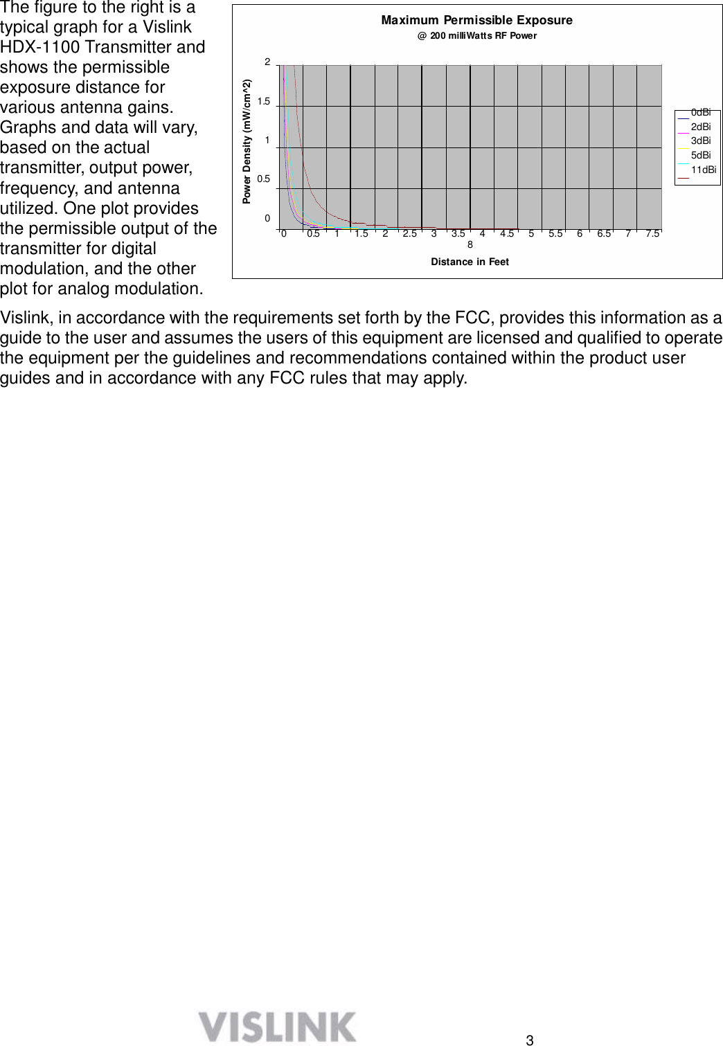
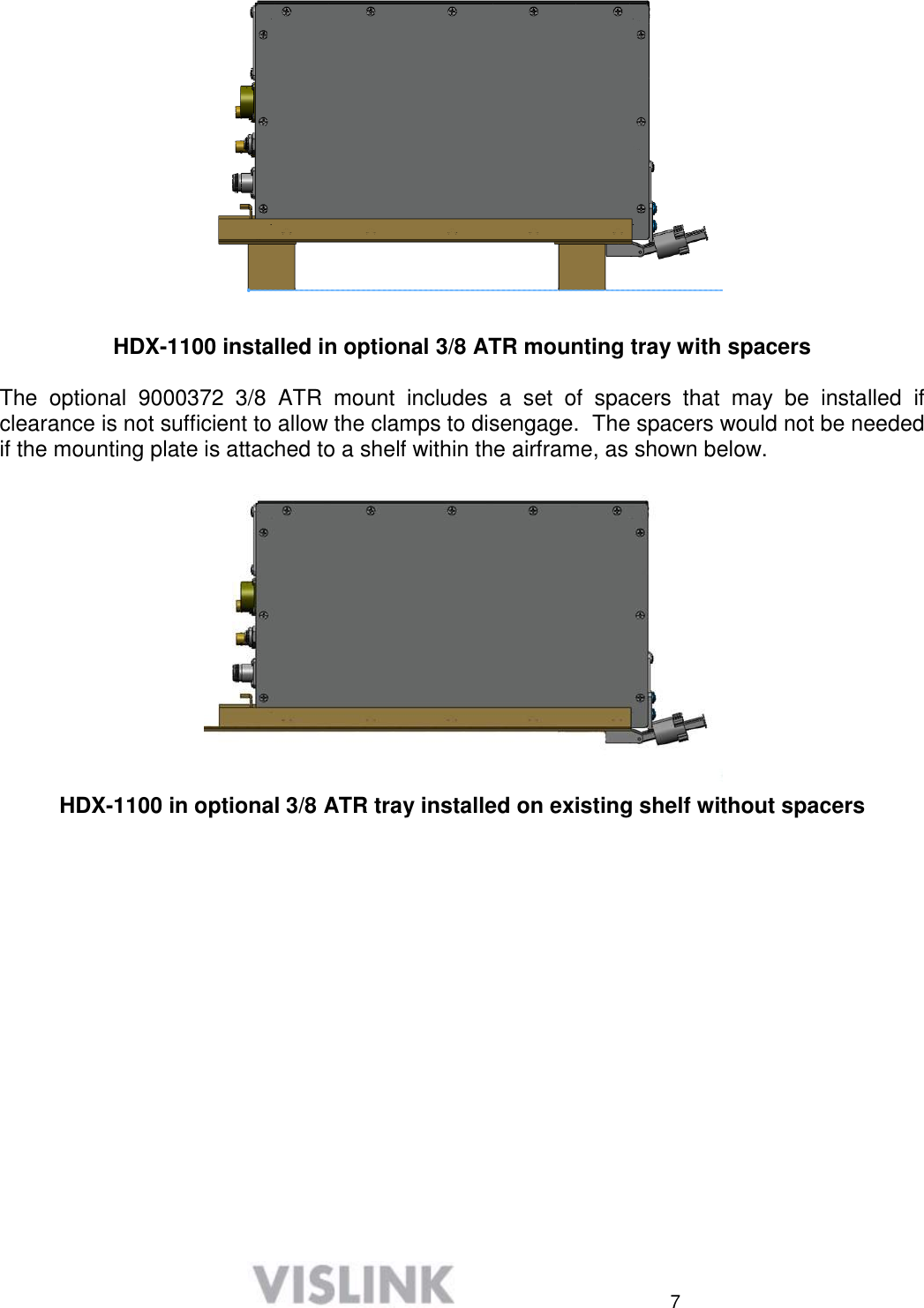
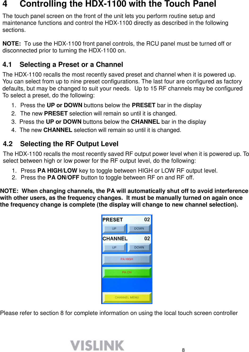
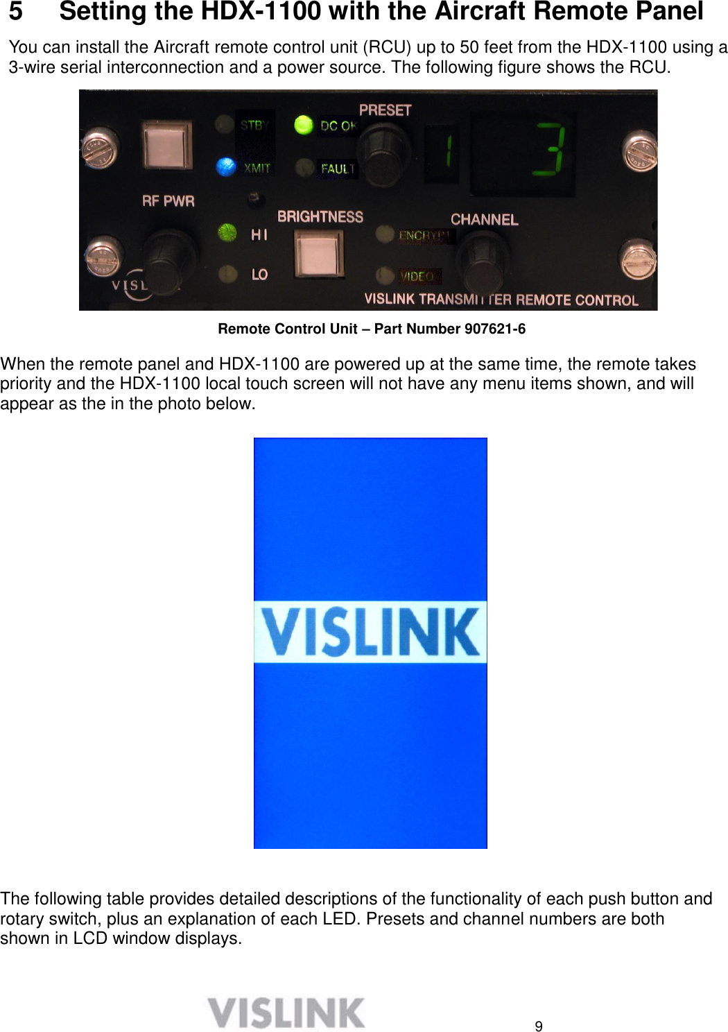
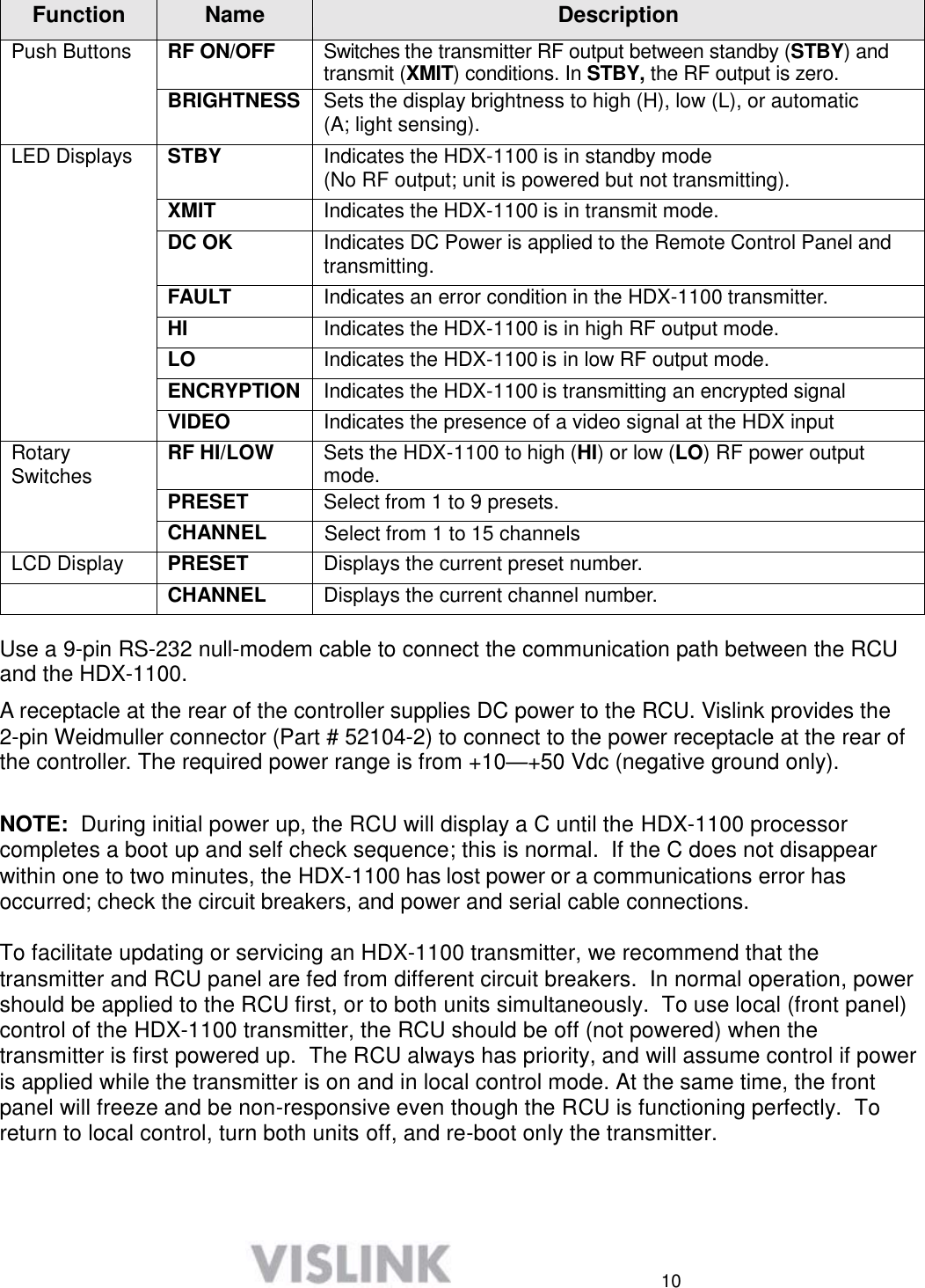
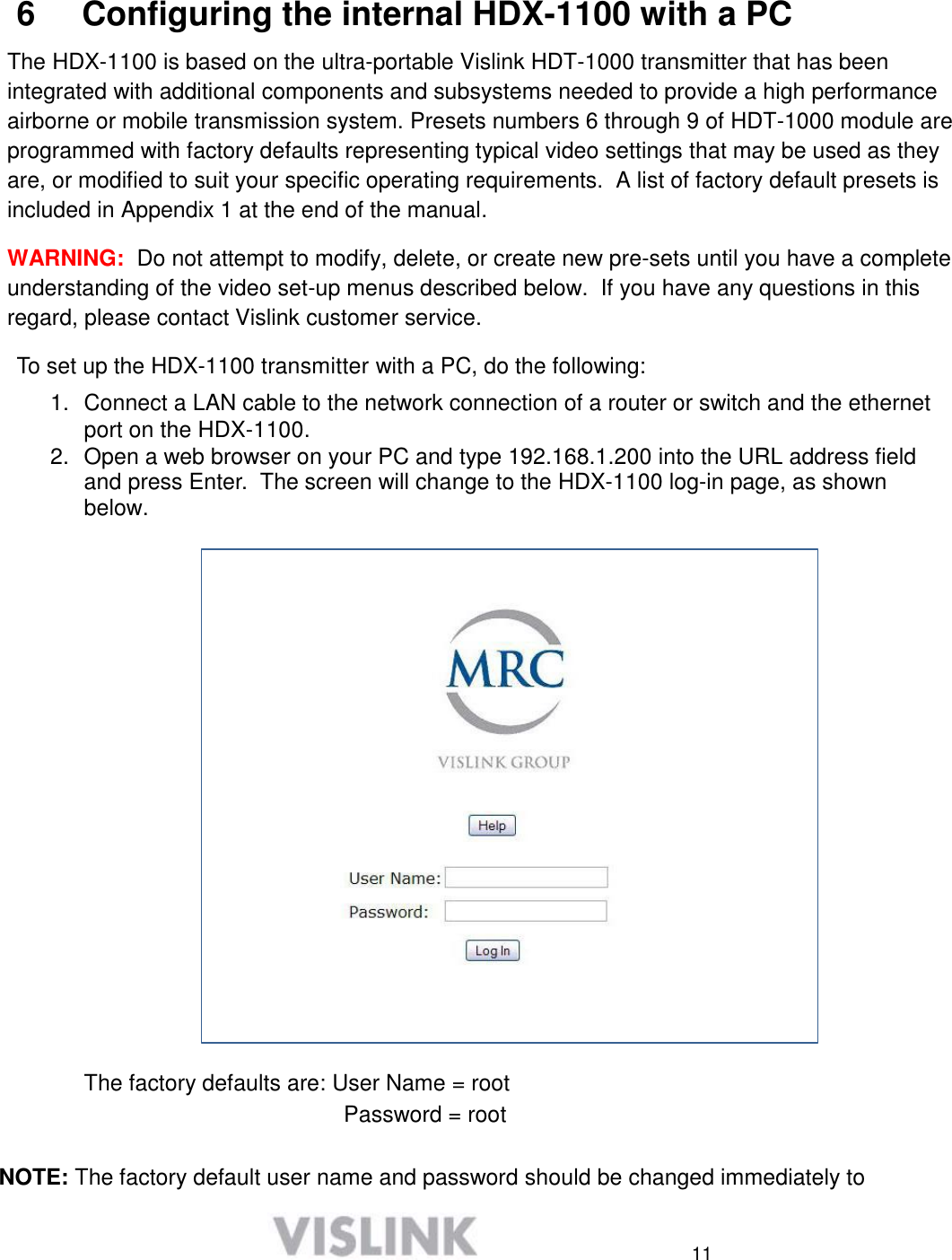
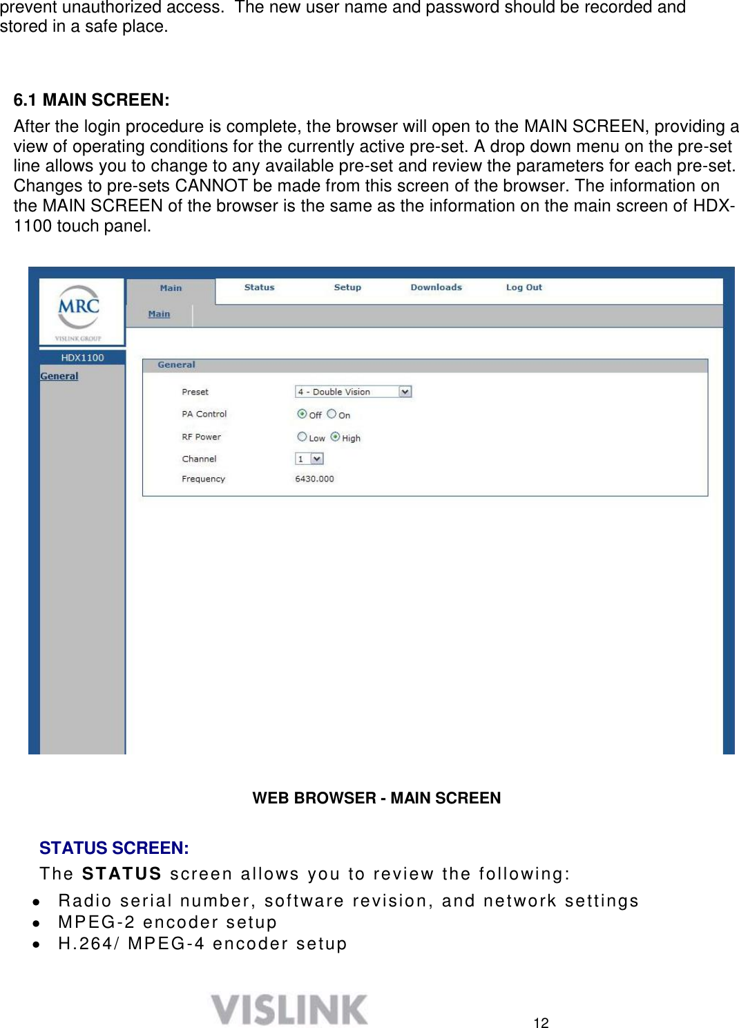
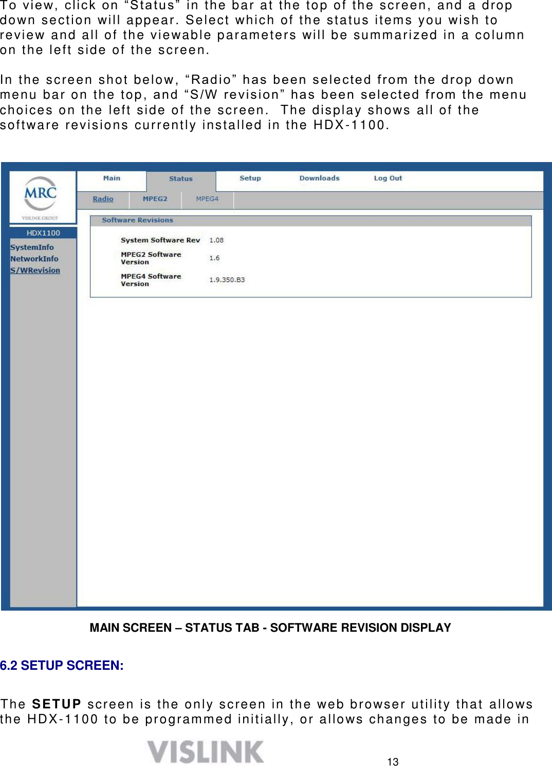
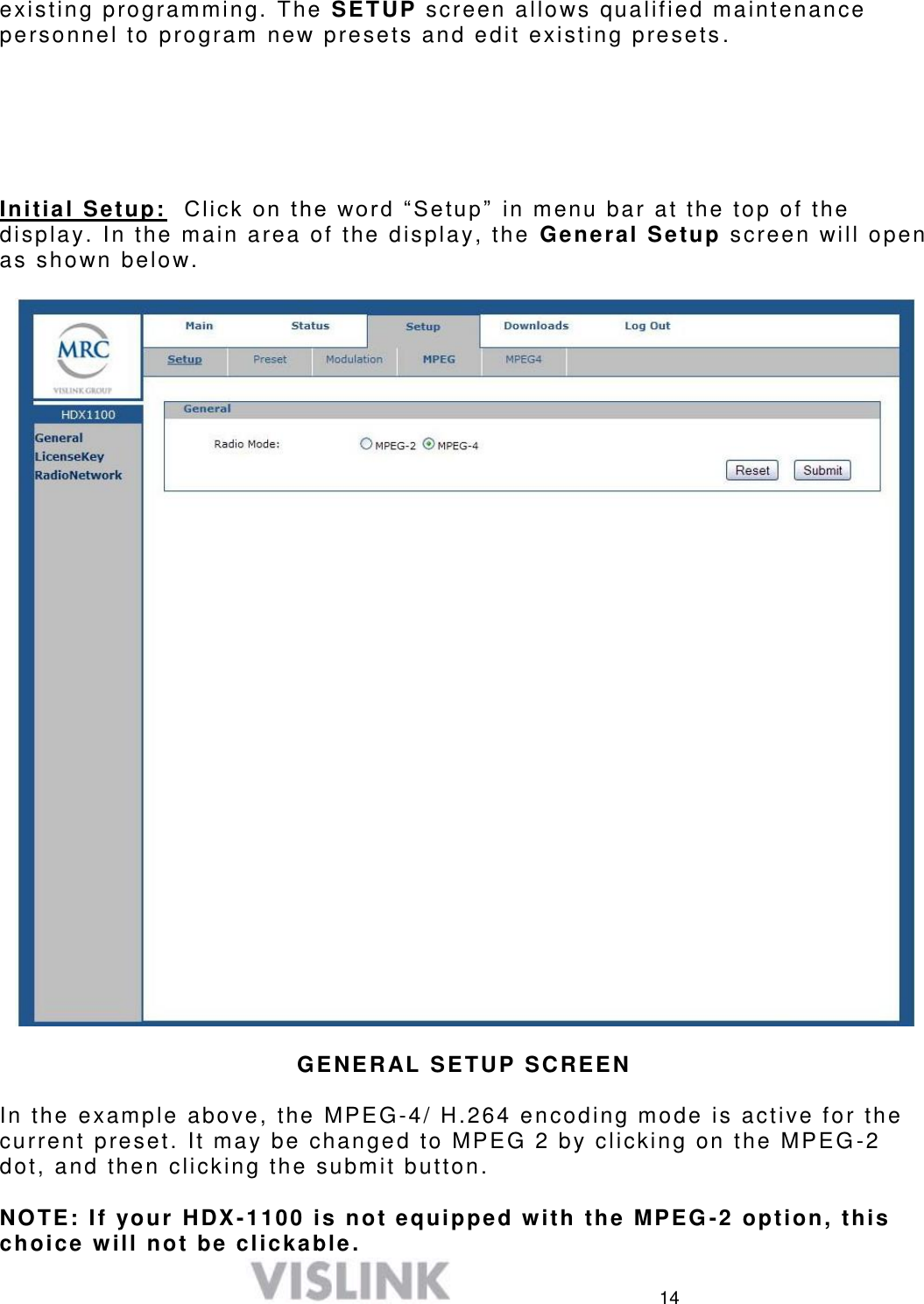
User manual HDX1100S

      HDX-1100  Aircraft/Terrestrial High Power SD/HD  Video Transmitter                                       User and Technical Manual  Manual Part No. 400609-1 Rev. XX - March  2011            PRELIMINARY COPY
         Copyright © 2010 Part number 400609-1 Printed in U.S.A. Authorized EU representative: Vislink PLC Quality Certification  Vislink is certified to ISO 9001:2008. The Vislink trademark and other trademarks are registered trademarks in the United States and/or other countries. Microsoft®, Windows®, and Internet Explorer® are registered trademarks of Microsoft Corporation in the United States and/or other countries. Proprietary Material  The information and design contained within this manual was originated by and is the property of Vislink. Vislink reserves all patent proprietary design, manufacturing, reproduction use, and sales rights thereto, and to any articles disclosed therein, except to the extent rights are expressly granted to others. The foregoing does not apply to vendor proprietary parts. Vislink has made every effort to ensure the accuracy of the material contained in this manual at the time of printing. As specifications, equipment, and this manual are subject to change without notice, Vislink assumes no responsibility or liability whatsoever for any errors or inaccuracies that may appear in this manual or for any decisions based on its use. This manual is supplied for information purposes only and should not be construed as a commitment by Vislink. The information in this manual remains the property of Vislink and may not be used, disclosed, or reproduced in any form whatsoever, without the prior written consent of Vislink. Vislink reserves the right to make changes to equipment and specifications of the product described in this manual at any time without notice and without obligation to notify any person of such changes. General Safety Information  The following safety requirements, as well as local site requirements and regulations, must be observed by personnel operating and maintaining the equipment covered by this manual to ensure awareness of potential hazards. This equipment has been tested and found to comply with the limits for a Class A digital device, pursuant to Part 15 of the FCC Rules. These limits are designed to provide reasonable protection against harmful interference when the equipment is operated in a commercial environment. This equipment generates, uses, and can radiate radio frequency energy. If not installed and used in accordance with the instruction manual, it may cause harmful interference to radio communications. Operation of this equipment in a residential area is likely to cause harmful interference in which case the user will be required to correct the interference at his own expense. About this Manual  This manual is intended for use by qualified operators, installers, and service personnel. Users of this manual should already be familiar with basic concepts of radio, video, and audio. For information about terms in this manual, see Glossary of Terms and Abbreviations (Part No. 400576-1). Pay special attention to Notes, Cautions, and Warnings. Read Notes for important information to assist you in using and maintaining the equipment. Follow CAUTIONS to prevent damage to the equipment. Follow WARNINGS to prevent personal injury or death. Symbols  The following symbols may be on the equipment or in this manual: WARNING: General Warning. Risk of Danger.  Frame or Chassis Ground: Identifies the frame or chassis terminal. WARNING: Risk of Electric Shock.  Earth Ground: Identifies the earth ground terminal. CAUTION: Electrostatic Discharge.   Possible Damage to Equipment.  Fuse (either icon): Identifies fuses or their location.  Protective Earth Ground: Identifies any terminal intended for connection to an external conductor for protection against elec- tric shock in case of a fault, or the terminal on a protective earth electrode. Waste Electrical and Electronic Equipment (WEEE): The product must not be disposed of with other waste. You must dispose of the waste equipment by handing it over to a desig- nated collection point for recycling.  101 Billerica Avenue, Building 6 North Billerica, MA 01862 USA +1-978-671-5700
 1 1  About the HDX-1100  The KamelyonTM HDX-1100 high power digital microwave transmitter is a ruggedized unit designed to support high quality video and data transmission in airborne and mobile applications, where vibration, shock, humidity, and temperature swings are everyday occurrences.   The HDX-1100 is compliant with aircraft industry mounting standards, making it perfectly suited for airborne or ground based mobile platforms. Typical applications include real time video for law enforcement, public safety, fire, utility, and other agency based surveillance tasks.  The HDX-1100 includes an H.264/MPEG-4 encoder that provides standard or high definition (SD or HD) video on DVB-T/ COFDM, or Vislink RangeMasterTM  single carrier modulation.  An MPEG-2 encoder option is available to support legacy receivers.    Video inputs may be configured for composite NTSC or PAL in standard analog formats, or digital video in SDI, HD-SDI, or ASI formats. Other inputs include two full range audio channels, and an RS-232 data channel.   The transmitter RF output is 8W in high power mode, and about 4 W in low power mode.  The HDX-1100 may be operated via the touch screen user interface (see Section 4), however it is typically controlled by an optional aircraft remote panel (RCU) (see Section 5). Initial HDX-1100 programming and presets should be configured via PC using the integrated web browser utility (see Section 6).   2  Operating in Safety  Guidelines for safe operation are derived from OET bulletin 65, August 1997, as recommended by the Federal Communications Commission (FCC).  WARNING  High levels of RF power are present in the unit. Exposure to RF or microwave power can cause burns and may be harmful to health. Remove power from the unit before disconnecting any RF cables and before inspecting damaged cables and/or antennas. Avoid standing in front of high gain antennas (such as a dish antenna) and never look into the open end of a waveguide or cable where RF power may be present.  The HDX-1100, operated without an antenna will not create RF energy exceeding 1.0 mW/cm2, the FCC limit for exposure. Connecting an antenna to the unit greatly enhances the potential for harmful exposure, and you must maintain a certain distance from the radiator. The following table shows the Maximum Permissible Exposure (MPE) safe distances from the antenna.
 2 Antenna Gain (dB1) 0 2 3 5 11 Safe Distance (cm) 4 6 6 8 15 Safe Distance (in) 1.57 2.36 2.36 3.15 5.9  Note  Hazardous RF radiation limits and recommended distances may vary by country. Observe all applicable state and federal regulations when using this transmitter.  To perform calculations to understand the safe exposure margin (MPE), use the following formula suggested by OET 65. The calculations provided are for common antennas often used in the mobile microwave environment.  Calculating MPE  EIRP = P * (10 ^ (G / 10)) = (antilog of G/10) * P  P = RF power delivered to the antenna in mW G = Power gain of the antenna in the direction of interest relative to an isotropic radiator R = distance to the center of radiation of the antenna in centimeters S = MPE in mW/cm² (milliwatts per square centimeters) Conversions  dBi to numeric gain = Antilog (dBi/10) Feet to centimeters = Feet * 30.48 Centimeters to Feet = cm * .0328 4 π = 12.57 User Input  RF power delivered to the antenna = Watts Antenna gain (referenced to isotropic antenna) = dBi Distance from the center of radiation = Feet Calculation steps:  1.  [P] RF power input. Watts to milliwatts = Watts * 1000 2.  [G] Antenna gain dBi. Numeric gain = Antilog (dBi/10) 3.  [EIRP] Multiply P * G 4.  [R] Centimeters to feet = Centimeters * .0328 5.  Square R 6.  Multiply R² * 4π 7.  [S] Divide (R² * 4π) into EIRP S = Power Density in milliwatts per square centimeters.  Note  At frequencies above 1500 MHz, S must not be greater than 1.  Reference  FCC OET Bulletin 65, August 1997 - Evaluating Compliance with FCC Guidelines for Human Exposure to Radio Frequency Electromagnetic Fields
 3 Power Density (mW/cm^2) The figure to the right is a typical graph for a Vislink HDX-1100 Transmitter and shows the permissible exposure distance for various antenna gains. Graphs and data will vary, based on the actual transmitter, output power, frequency, and antenna utilized. One plot provides the permissible output of the transmitter for digital modulation, and the other plot for analog modulation.      2   1.5   1   0.5   0   Maximum Permissible Exposure @ 200 milliWatts RF Power              0       0.5     1     1.5     2     2.5     3     3.5     4     4 .5     5     5.5     6     6.5     7     7.5     8 Distance in Feet         0dBi 2dBi 3dBi 5dBi 11dBi  Vislink, in accordance with the requirements set forth by the FCC, provides this information as a guide to the user and assumes the users of this equipment are licensed and qualified to operate the equipment per the guidelines and recommendations contained within the product user guides and in accordance with any FCC rules that may apply.
 4 3  Installing an HDX-1100 Transmitter  The HDX-1100 is built in an ARINC compliant 3/8 ATR housing, and was designed primarily for aircraft operation.  It is also suitable for general mobile applications, including terrestrial vehicles. The transmitter and its remote control panel (RCU) have been tested and certified to be compliant with RTCA DO-160F, as recognized by the FAA and other global agencies that regulate aircraft operation and safety. NOTE: Aircraft installation must be performed by certified aircraft maintenance personnel.            TOUCH SCREEN DISPLAY                     AIR VENT                                                                                  HOLD DOWN BRACKETS   (used with optional mounting kit)         HDX-1100 FRONT PANEL
 5           DC POWER, AUDIO, DATA, REMOTE   VIDEO 1 – COMPOSITE NTSC or PAL   VIDEO 2 – COMPOSITE NTSC or PAL   SDI or HD-SDI DIGITAL VIDEO INPUT    ASI INPUT FROM EXT. ENCODER   WEB BROWSER MANAGEMENT  (Ethernet)  DC CIRCUIT BREAKER   RF OUTPUT                HDX-1100 REAR PANEL  The following electrical connections must be made to place the HDX-1100 in service.   o  Video Inputs and connector types:   Video 1:  BNC female – NTSC or PAL composite   Video 2 - BNC female – NTSC or PAL composite (NOTE: This is the DoubleVision input, usable in MPEG-4 SD mode only)   SDI: BNC female  - SDI or  HD-SDI (configurable)   ASI input: BNC female – accepts signal from an external encoder o RJ-45 jack   10/100 web browser interface for set-up & maintenance o  RF Output: Type N female – 50 Ohms o  DC power in, audio, auxiliary data, and remote control, are all connected via 26 pin Bendix chassis receptacle. A mating connector is supplied with each unit, and must be wired per the drawing in section 7.3   10
 6 NOTE:  There is a 10 AMP DC circuit breaker on front panel of HDX-1100.  If the power to this breaker is fed from another circuit breaker in the aircraft, the HDX-1100 breaker should be left in the on position. To operate the breaker: push in = ON, pull out = OFF, a manual reset is required after the breaker trips.                 HDX-1100 MECHANICAL OUTLINE  There are two possible mounting configurations, which should provide an installer with enough flexibility to work in most situations:   1)  For situations where the transmitter will be mounted on a flat surface, four captive nuts have been installed in the transmitter side plate. 2)  An optional aircraft mounting kit (part # 9000372) may be ordered. The kit includes an ARINC compliant low profile tray with quick release clamps, and removable spacers.         Optional 9000372 3/8 ATR mounting kit with removable spacers
 7   HDX-1100 installed in optional 3/8 ATR mounting tray with spacers  The  optional  9000372  3/8  ATR  mount  includes  a  set  of  spacers  that  may  be  installed  if clearance is not sufficient to allow the clamps to disengage.  The spacers would not be needed if the mounting plate is attached to a shelf within the airframe, as shown below.     HDX-1100 in optional 3/8 ATR tray installed on existing shelf without spacers
 8 4  Controlling the HDX-1100 with the Touch Panel  The touch panel screen on the front of the unit lets you perform routine setup and maintenance functions and control the HDX-1100 directly as described in the following sections.  NOTE:  To use the HDX-1100 front panel controls, the RCU panel must be turned off or disconnected prior to turning the HDX-1100 on.    4.1  Selecting a Preset or a Channel  The HDX-1100 recalls the most recently saved preset and channel when it is powered up. You can select from up to nine preset configurations. The last four are configured as factory defaults, but may be changed to suit your needs.  Up to 15 RF channels may be configured To select a preset, do the following:  1.  Press the UP or DOWN buttons below the PRESET bar in the display 2.  The new PRESET selection will remain so until it is changed. 3.  Press the UP or DOWN buttons below the CHANNEL bar in the display 4.  The new CHANNEL selection will remain so until it is changed.  4.2  Selecting the RF Output Level  The HDX-1100 recalls the most recently saved RF output power level when it is powered up. To select between high or low power for the RF output level, do the following:  1.  Press PA HIGH/LOW key to toggle between HIGH or LOW RF output level. 2.  Press the PA ON/OFF button to toggle between RF on and RF off.  NOTE:  When changing channels, the PA will automatically shut off to avoid interference with other users, as the frequency changes.  It must be manually turned on again once the frequency change is complete (the display will change to new channel selection).      Please refer to section 8 for complete information on using the local touch screen controller
 9   5  Setting the HDX-1100 with the Aircraft Remote Panel  You can install the Aircraft remote control unit (RCU) up to 50 feet from the HDX-1100 using a 3-wire serial interconnection and a power source. The following figure shows the RCU.                 Remote Control Unit – Part Number 907621-6  When the remote panel and HDX-1100 are powered up at the same time, the remote takes priority and the HDX-1100 local touch screen will not have any menu items shown, and will appear as the in the photo below.       The following table provides detailed descriptions of the functionality of each push button and rotary switch, plus an explanation of each LED. Presets and channel numbers are both shown in LCD window displays.
 10  Function Name Description Push Buttons RF ON/OFF Switches the transmitter RF output between standby (STBY) and transmit (XMIT) conditions. In STBY, the RF output is zero.  BRIGHTNESS Sets the display brightness to high (H), low (L), or automatic (A; light sensing). LED Displays STBY Indicates the HDX-1100 is in standby mode (No RF output; unit is powered but not transmitting). XMIT Indicates the HDX-1100 is in transmit mode. DC OK Indicates DC Power is applied to the Remote Control Panel and transmitting. FAULT Indicates an error condition in the HDX-1100 transmitter. HI Indicates the HDX-1100 is in high RF output mode. LO Indicates the HDX-1100 is in low RF output mode. ENCRYPTION Indicates the HDX-1100 is transmitting an encrypted signal VIDEO Indicates the presence of a video signal at the HDX input Rotary Switches RF HI/LOW Sets the HDX-1100 to high (HI) or low (LO) RF power output mode. PRESET Select from 1 to 9 presets. CHANNEL   Select from 1 to 15 channels LCD Display PRESET Displays the current preset number.  CHANNEL Displays the current channel number.  Use a 9-pin RS-232 null-modem cable to connect the communication path between the RCU and the HDX-1100.  A receptacle at the rear of the controller supplies DC power to the RCU. Vislink provides the 2-pin Weidmuller connector (Part # 52104-2) to connect to the power receptacle at the rear of the controller. The required power range is from +10—+50 Vdc (negative ground only).   NOTE:  During initial power up, the RCU will display a C until the HDX-1100 processor completes a boot up and self check sequence; this is normal.  If the C does not disappear within one to two minutes, the HDX-1100 has lost power or a communications error has occurred; check the circuit breakers, and power and serial cable connections.    To facilitate updating or servicing an HDX-1100 transmitter, we recommend that the transmitter and RCU panel are fed from different circuit breakers.  In normal operation, power should be applied to the RCU first, or to both units simultaneously.  To use local (front panel) control of the HDX-1100 transmitter, the RCU should be off (not powered) when the transmitter is first powered up.  The RCU always has priority, and will assume control if power is applied while the transmitter is on and in local control mode. At the same time, the front panel will freeze and be non-responsive even though the RCU is functioning perfectly.  To return to local control, turn both units off, and re-boot only the transmitter.
 11     6  Configuring the internal HDX-1100 with a PC  The HDX-1100 is based on the ultra-portable Vislink HDT-1000 transmitter that has been integrated with additional components and subsystems needed to provide a high performance airborne or mobile transmission system. Presets numbers 6 through 9 of HDT-1000 module are programmed with factory defaults representing typical video settings that may be used as they are, or modified to suit your specific operating requirements.  A list of factory default presets is included in Appendix 1 at the end of the manual.   WARNING:  Do not attempt to modify, delete, or create new pre-sets until you have a complete understanding of the video set-up menus described below.  If you have any questions in this regard, please contact Vislink customer service.    To set up the HDX-1100 transmitter with a PC, do the following:  1.  Connect a LAN cable to the network connection of a router or switch and the ethernet port on the HDX-1100. 2.  Open a web browser on your PC and type 192.168.1.200 into the URL address field and press Enter.  The screen will change to the HDX-1100 log-in page, as shown below.     The factory defaults are: User Name = root Password = root  NOTE: The factory default user name and password should be changed immediately to
 12 prevent unauthorized access.  The new user name and password should be recorded and stored in a safe place.    6.1 MAIN SCREEN: After the login procedure is complete, the browser will open to the MAIN SCREEN, providing a view of operating conditions for the currently active pre-set. A drop down menu on the pre-set line allows you to change to any available pre-set and review the parameters for each pre-set. Changes to pre-sets CANNOT be made from this screen of the browser. The information on the MAIN SCREEN of the browser is the same as the information on the main screen of HDX-1100 touch panel.        WEB BROWSER - MAIN SCREEN  STATUS SCREEN:    The STATUS screen allows you to review the following:   Radio serial number, software revision, and network settings   MPEG-2 encoder setup   H.264/ MPEG-4 encoder setup
 13 To  vie w,  c l ic k on ―Status‖  in the bar at the top of the screen, and a drop down section will appear. Select which of the status items you wish to review and all of the viewable parameters will be summarized in a column on the left side of the screen.   In the screen shot below,   ― R a d i o ‖ h as  b e en   s e l e c te d  f rom the drop down menu bar on the top,   a n d   ―S/W   re visi on ‖  ha s  been  se le ct ed f rom  the menu choices on the left side of the screen.  The display shows all of the software revisions currently installed in the HDX -1100.       MAIN SCREEN – STATUS TAB - SOFTWARE REVISION DISPLAY  6.2 SETUP SCREEN:    The SETUP screen is the only screen in the web browser utility that  allows the HDX-1100 to be programmed initially, or allows changes to be made in
 14 existing programming. The SETUP screen allows qualified maintenance personnel to program new presets and edit existing presets .       Initial Setup:  C l ick  on the word ―Se tup ‖  in menu bar at the top of the display. In the main area of the display, the  General Setup screen will open as shown below.      GENERAL SETUP SCREEN  In the example above, the MPEG-4/ H.264 encoding mode is active for the current preset. It may be changed to MPEG 2 by clicking on the MPEG -2 dot, and then clicking the submit button.  NOTE: If your HDX-1100 is not equipped with the MPEG -2 option, this choice will not be clickable.
 15  IMPORTANT: When RESET and SUBMIT buttons are present in a setup screen, the SUBMIT button is used to enter new data into the program while the RESET button will cancel any programming action currently entered, but not yet submitted. Clicking the RESET will return you to the previous screen.   To view the HDX-1100 serial number, or re-enter the license key, select License Key in the column on the left side of the display, and the screen below will appear:     License Key Screen   The Serial Numbers are entered at the factory, and are always visible in the space provided.  The License Keys are never visible, except when they are being entered at the factory, or reentered in the field after a repair has been made. In both cases the License Key numbers will disappear as soon as the submit button is pushed. The License Key number is provided to the
 16 customer along with the factory data.    6.3 Radio Network Screen:  The values initially found in the IP address, Subnet, and Gateway dialog boxes of the radio network screen are factory defaults.  These should be changed to match your specific network requirements. Changes are accomplished by entering the new values  in the dialog boxes then clicking on the submit button. If an error is made during the entry process, simply click the reset button to return to the previous screen , from which the process can be restarted.      SETUP - RADIO NETWORK SCREEN
 17    6.4 CONFIGURING PRESETS  For maximum flexibility, a complete set of parameters must be defined for each preset that is programmed into the HDX -1100. To begin the process, select Preset from the drop-down menu in the bar at the top of the display, and the screen shown below will appear.    PRESET SCREEN  The Preset Text box accepts user input to identify each preset is. Text is entered by the user for each preset, and saved with the  Submit button.  To initiate programming or make a change, click on Preset Number and choose the preset you wish to program or change from the drop down menu.  Enter the new text in the Preset Text dialog box, and click the
 18 Submit button when you are satisfied with the result. Next, click on the Modulation button in the menu bar at the top of the screen.   MODULATION SETUP SCREEN  Modulation setup determines the bit rate that the transmitter can send to the receiving station for each preset. Lower bit rates will work better in situations where extreme fades, interference, or  multipath are present. Higher bit rates are not as robust; however, they may be required for highest quality HD transmission.   The maximum available bit rate is directly related to  the modulation type and the channel bandwidth. The following tables provide a complete summary of modulation settings for both 6 and 8 MHz  DVB-T bandwidths as a function of bit rate. In order to comply with FCC emission standards, a 6 MHz DVB-T bandwidth is the maximum allowed in an 8 MHz wide RF channel, while an 8 MHz DVB-T bandwidth can be used in a 10 MHz or wider RF channel. A 10 MHz DVB-T bandwidth can support a total bit rate 33% higher than an 8 MHz channel, if all other factors are equal.
 19   1/4 1/8 1/16 1/321/2 3.732 4.147 4.391 4.5242/3 4.976 5.529 5.855 6.0323/4 5.599 6.221 6.587 6.7865/6 6.221 6.912 7.318 7.5407/8 6.532 7.257 7.684 7.9171/2 7.465 8.294 8.782 9.0482/3 9.932 11.059 11.709 12.0643/4 11.197 12.441 13.173 13.5725/6 12.441 13.824 14.637 15.0807/8 13.063 14.515 15.369 15.8341/2 11.197 12.441 13.173 13.5722/3 14.929 16.588 17.564 18.0963/4 16.796 18.662 19.760 20.3585/6 18.662 20.735 21.955 22.6207/8 19.595 21.772 23.053 23.75116-QAM64-QAMAvailable bitrates (Mbit/s) for a DVB-T system in 6 MHz channelsModulationCoding rateGuard intervalQPSK Modulation setting versus bitrate for a 6 MHz DVB-T bandwidth  IMPORTANT: The 6 MHz DVB-T bandwidth setting is the maximum that may be used in an 8 MHz wide RF channel.   1/4 1/8 1/16 1/321/2 4.976 5.529 5.855 6.0322/3 6.635 7.373 7.806 8.0433/4 7.465 8.294 8.782 9.0485/6 8.294 9.216 9.758 10.0537/8 8.709 9.676 10.246 10.5561/2 9.953 11.059 11.709 12.0642/3 13.271 14.745 15.612 16.0863/4 14.929 16.588 17.564 18.0965/6 16.588 18.431 19.516 20.1077/8 17.418 19.353 20.491 21.1121/2 14.929 16.588 17.564 18.0962/3 19.906 22.118 23.419 24.1283/4 22.394 24.882 26.346 27.1445/6 24.882 27.647 29.273 30.167/8 26.126 29.029 30.737 31.66816-QAMAvailable bitrates (Mbit/s) for a DVB-T system in 8 MHz channelsModulationCoding rateGuard intervalQPSK64-QAM Modulation setting versus bitrate for an 8 MHz DVB-T bandwidth
 20  NOTE: External encoder required for bit rates in yellow highlight.    Other factors that impact the total available bit rate are the code rate and the guard interval settings.   Coding Rate Setting: This setting determines the amount of forwa rd error correction used to reduce video data loss under adverse conditions . If the code rate is set to ½, this means that half of the available data rate is being used for error correction, while the rest is available  for video. A code rate of 1/2 uses the most bandwidth for error correction, but provides the highest degree of protection against video breakup.   Guard Interval: The primary purpose of the guard interval is to  provide resistance to multipath and co-channel interference.  Longer guard intervals are used in dense metro areas, where high levels of multipath are expected. A guard interval of 1/4 is the longest, while 1/32 is the shortest.  NOTE: W hen programming an HDX-1100, a good rule of thumb is to program several presets with varying amounts o f error correction to be able to quickly switch quickly from a very robust, low data rate setting, to a less robust but higher-speed setting.    6.5 VIDEO AND AUDIO INPUT SETUP  The video and audio inputs must be configured for each preset.  To initiate this procedure, click on MPEG-2 or MPEG-4 in the bar at the top of the screen, and then click on Video on the left side of the screen.  Two dialogue boxes will appear: Video In, and, Encryption.   See next graphic for details. IMPORTANT:  When equipped with the MPEG-2 encoding option, HDX-1100 presets may be programmed all in MPEG-2 mode, all in H.264/MPEG-4 mode, or as a mix of the two. For example, the first five presets may be programmed for MPEG-2 encoding, while the remaining four are programmed for H.264/MPEG-4 encoding.  Video Settings: Click on Video In and select the desired parameters from the drop down table. Available parameters include the input configuration, such as composite or SDI, as well as video resolution.  MPEG-2 settings differ from MPEG-4 settings, and require additional choices to be made, including   NOTE: Input A is the normal video input and must always be set up. When using the
 21 DoubleVision option, Input B must also be set up.     Video and Encryption Mode set-up Screen     If encryption is to be used, select Encryption from the Video drop down menu, and configure the encryption mode and key as required for encrypted preset, and click Submit..  Note:  For 128-bit encryption, enter 32 hexadecimal characters.  For 256-bit encryption, enter 64 hexadecimal characters.
 22 6.6 CHANNEL SETUP   Normally, a customer specified channel plan is set up at the factory when the HDX-1100 is built, however, additional channels may be added at any time, or existing channels may be redefined if necessary. These changes can only be made by qualified technical service personnel.    CHANNEL PLAN SETUP SCREEN  For each channel to be added or set up, enter the correct frequency information in the dialog box on the right-hand side of the screen corresponding to the desired channel number. Once you have completed and checked the frequency entry, click the submit button and the new frequencies will appear in the dialog boxes on the left side of the screen.
 23 6.7  Recalling a Preset Configuration from a PC  1.  Select Preset from the Radio drop down menu. 2.  Select the preset number and click Load. The relevant parameters will be populated under Video and Radio. 3. Select ―save‖ to change to the active preset.  Note  The Encryption code will not display.  Click Logout to finish setting up the HDX-1100  Once this procedure has been completed, the pre-sets that were established may be recalled using the aircraft remote panel.    NOTE:  The HDX-1100 transmit frequency settings may be configured via the web browser, or from the HDX-1100 front panel.  See section 7 for details.   7  HDX-1100 Program & Control Screens     Main Screen    Preset :  Displays current pre-set selection Up – Down:  Steps through pre-sets (1-9) Channel:  Displays current channel selection   Up – Down:  Steps through channels (1 -15) PA HIGH/ LOW: toggles between high & low power PA ON/OFF:  Switches PA ON or OFF         Channel Menu: Will go to Channel Menu screen
 24 MAIN SCREEN OPERATION  When operating the HDX-1100 transmitter in local mode (touch screen active), the main screen will be displayed first.  The current preset and channel selections are controlled by touching the up and down buttons below the respective sections of the display. For example, to move to a lower channel, touch the down arrow below the CHANNEL bar in the main screen.     High or low power may be selected by touching the PA HIGH/ LOW button, which will toggle the setting between HIGH and LOW each time the button is touched. The label will change to confirm that the new selection has been completed.   PA ON or PA OFF settings are selected by touching the PA ON/OFF button, which will toggle the setting between ON and OFF each time the button is touched. The label will change to confirm that the new selection has been completed.   NOTE:  When changing channels, the PA will automatically shut off to avoid interference with other users, as the frequency changes.  It must be manually turned on again once the frequency change is complete (the display will change to new channel selection).        Channel Menu   Channel:  Displays current channel selection MHz:  Frequency of current channel Left/Right Arrows :  move cursor left or right   Up – Down:  Changes the selected frequency digit Set Frequency:  Touch this button to set or change current channel Back:  Will save setting and return to Main screen        7.1  SETTING OR MODIFYING CHANNEL FREQUENCY  To initiate or modify a channel frequency, first select the channel assignment to be modified on the main screen, then touch the CHANNEL MENU button on the main screen; the display will
 25 change to the screen shown above.    To access the channel assignment menu, first touch the SET FREQUENCY button on the screen. You will notice that one of the digits in the FREQUENCY bar will now have a black, blinking cursor.    Using the left and right arrows below the FREQUENCY bar, navigate the blinking cursor to the digit that will be changed first.  In the screen shot above for example, the current frequency of channel 2 is 6438.000 MHz, however you want to change this to 6455.000.       1)  Touch the set frequency button 2)  Using the arrows, move the cursor to the 3 (third digit) 3)  Touch the UP button once to change the 3 to a 4 4)  Move the cursor to the 8  (fourth digit)  5)  Touch the DOWN button three times to change the 8 to a 5 6)  Touch the BACK button to save the new frequency  If you wish to add or change another channel, go to that channel while in the main screen, then touch the channel menu button and repeat the process above.  This process must be repeated each time a channel is added or changed.
 26 8  HDX-1100 Specifications  The following figure shows the front, back, top, and side views of the HDX-1100.     • Dimensions: 3.65 x 7.62 x 12.68 inches (ARINC ATR 3/8 compliant size)  • Weight: 8 pounds (3.6 kg)  • Operating temperature: –10 °C to +55 °C; storage temperature: –40 °C to +75 °C  • Humidity: up to 95% relative and non-condensing  • Altitude: up to 20,000 feet (6,000 m)  8.1  Band and Frequency Options  You can order the HDX-1100 for the following frequency bands (others on special order):   Model  Band  Frequency Typical Power Consumption Frequency Stability Frequency Step Size HDX-1100L L 1.7—1.9 GHz 90W 2.5 ppm 250 Khz HDX-1100S S 2.0—2.5 GHz 90W 2.5 ppm 250 Khz HDX-1100C1 C1 3.1—3.5 GHz 90W 2.5 ppm 250 Khz HDX-1100C2 C2 4.4—5.0 GHz 90W 2.5 ppm 250 Khz HDX-1100C3 C3 6.4— 6.5  GHz 90W 2.5 ppm 250 Khz HDX-1100X X 8.1—8.5 GHz 90W 2.5 ppm 250 Khz  8.2  Video Input Connectors  SDI, HD-SDI and analog composite video inputs connect via BNC’s on the rear panel.           BNC Connector Pin Description  Signal  Ground Pin Signal Ring Ground
 27     8.3  DC POWER and CONTROL Connector  DC voltage for the HDX-1100 is +10 Vdc to +32 Vdc with reverse voltage protection. Ensure that the power being supplied matches the power required by the equipment.  I/O connector 26-Pin Male D connector pin-outs are shown in the following table:  Power Connector Pin Description Pin Description  A +DC Voltage in P Serial CTRL Output B +DC Voltage in R N/C C Audio 1 + input S N/C D Audio 1 -  input T Reserved E Audio 1 Shield/GND U Reserved F Audio 2 Shield/GND V Reserved G Audio 2 + input W Ethernet RX +  H Audio 2 - input X Ethernet RX - J Wayside Data Input Y Ethernet TX + K Wayside Data GND Z Ethernet TX - L N/C a Reserved M Serial CTRL Input b – DC Voltage in N Serial CTRL GND c – DC Voltage in  8.4  RF OUT Connector  The RF Output is a Type N female connector with a 50 Ω characteristic impedance.  N Connector Pin Description  Center RF Signal - 50Ω Ring Ground  8.5  Modulation  •  DVB-T (standard feature)  COFDM 2K CARRIER MODE PER ETSI EN 300 744  COFDM QPSK COFDM 16QAM COFDM 64QAM  •  RangeMasterTM (Optional feature)       Narrow Band SCM, programmable, 1–10 MHz bandwidth, QPSK only
 28 8.6 Encryption  Only one type of encryption can be installed in each transmitter, and it must be done at the factory. The choices are limited to:  • RCBC (Reverse Chain Block Ciphering)  •  AES 128-bit  •  AES 256-bit  Note  ASI  input streams are not encrypted   8.7  RF Output Power  • High Power Mode: Enables PA and supplies output power of 8 W (+ 39 dBm)  NOTE: An optional 10W (+40 dBm) amplifier is also available)   • Low Power Mode: Enables PA and supplies reduced output power of 3 to 6 dB  •  Impedance: 50 Ohms: 17 dB return loss, typical  •  Protection: Transmitters will not be damaged by an infinite VSWR at any phase angle at the RF output connector for an indefinite time.  NOTE: An optional 10W (+40 dBm) amplifier is also available)   8.8  Audio Characteristics  •  Two audio inputs are to be supported which can be both line, both microphone, or one of each.  8.9  Video Input Format  •  ASI: 188 byte, EN50083-9  • HD-SDI: SMPTE 292M   1920x1080i@ 25, 29.97, or 30 frames per second    SDI: SMPTE 259M   720 x 480i @ 25/30fps  720 x576i @ 25/30fps   Analog Composite: 1 V p/p TIA/EIA  RS170    720 x 480i NTSC 525   720 x 576i PAL 625 •  Wayside Data Rate: up to 115.2 kbps  •  Video input impedance: 75 Ohm unbalanced 8.10  Encoding: SD, HD in H.264 mode  Supports the following MPEG requirements:  • High Definition (HD)  •  Standard Definition (SD)
 29 •  Compression Type: AVC / H.264 / MPEG-4 Part 10  •  Compression Standard: ISO/IEC 14496-10  • Min Motion Est. Range: ±192 Horiz., ±128 Vert.  •  GOP Structure: I-only and IP; GOP Length: 1 to 100, Selectable  •  Profiles supported: BP@L4 with Interlaced support or higher, HiP@4.1  •  Video bit rates: ≤ 20 Mbps  •  System Latency, end-to-end delay exclusive of propagation delay: ≤ 4 frames  •  Transport Stream: AVC/H.264/MPEG-4 encapsulated into MPEG Transport Stream (ITU-T Rec. H.222.0 Amd 3)  •  Video Inputs: HD-SDI (SMPTE 250M) video input and 480p shall be mapped onto SMPTE 292M as defined in SMPTE 349M.  9  Local System Access and Management Interfaces The front panel of the HDX-1100 includes an LCD touch screen that allows radio operating parameters to be initially configured and later modified by maintenance personnel.  The touch screen provides the ability to recall and review and/or change the frequency of channel presets, turn the power amplifier on and on, switch between high power and low power modes, and gives visual feedback to maintenance personnel for each of the described actions. Future software updates will provide additional set-up capability, including the ability to set modulation constellation, guard interval, and Forward Error Correction, and will support saving any changes to a selected or new preset. NOTE: The HDX-1100 touch screen will allow local control only when the remote control (RCU) panel is disconnected, or powered down.  If the RCU panel is turned on or connected while the HDX-1100 is powered on, the RCU will take priority for as long as the units are powered on. The local touch screen will continue to display the last setting, but will not longer control transmission parameters.  To regain local control, the HDX-1100 must be powered down, and the RCU must be turned off or disconnected, before powering up the HDX-1100 again.  Once the boot-up sequence is completed in local control mode, the main screen will be shown, as illustrated in 8.1 below.
 30 10 Getting Support for Your HDX-1100  You can contact the Vislink Technical Support staff as follows:  24- Hour Worldwide Technical Support  Americas   USSupport@vislink.com    888.777.9221 (US & Canada)   +1 978.671.5929 (outside of US & Canada)  United Kingdom  UKSupport@vislink.com   +44 (0) 1442 431 410  Asia Pacific  APACsupport@vislink.com +65 8189 3040 When you contact Technical Support, include the following information:  •  Model number and serial number of the unit (located on a label on the bottom of each unit).  •  Approximate purchase date.  There are no supported field repairs to the HDX-1100. Return the unit for factory repair.   CAUTION  If you attempt field repair, you risk damaging your equipment. If your equipment is under warranty, you may also affect your warranty coverage. The HDX-1100 requires specialized test equipment and software to calibrate operating characteristics after repair.
 31 11.0 Glossary of Terms  ARINC    Aeronautical Radio, Inc. Maintains standards for line-replaceable units in a     aviation, defense, government, healthcare and other industries. ASI    Asynchronous Serial Interface. B-Frame   Contains difference information from the preceding and following I- or P-frame within a GOP COFDM   Coded Orthogonal Frequency Division Multiplexing DVB-T    Digital Video Broadcast - Terrestrial ETSI     European Telecommunications Standards Institute FEC    Forward Error Correction. GOP  A group of successive pictures within a coded video stream. It may be made up of I frames only, I and B frames, or I, B, and P frames. Guard Interval  An interval between transmissions to prevent data loss and reduce interference. H.264  Synonymous with MPEG4, H.264 is an Advanced Video Coding standard providing high quality at lower bit rates than MPEG-2 / H.263. HD     High Definition Television I-Frame  A fixed image and which is independent of other picture types  P-Frame  Predictive frame; contains motion-compensated difference information from the preceding frame PID  13-bit packet ID used to identify an elementary stream in an MPEG transport stream QAM     Quadrature Amplitude Modulation (16QAM or 64 QAM)  QPSK     Quadrature Phase Shift Keying RF     Radio Frequency RS232  Recommended Standard 232 is a serial binary single-ended data and control standard for serial ports. SD  Standard Definition refers digital video resolution not exceeding 480 lines in an interlaced format. The aspect ratio may be 4:3 or 16:9. SDI    Serial Digital Interface, eg. SMPTE 259M standard
 32 Appendix 1  The table and chart below summarizes the FCC channel plan for the 6.5 GHz band, as specified in part 101 of the commission’s rules and regulations.  Please note the restrictions on modulation bandwidth for the 8 MHz channels, as well as use of offsets within the 25 MHz channels. For US domestic applications, this is the default channel plan that is loaded into an HDX 1000 prior to shipment. This plan may be modified by the user to suit specific requirements. For application outside of the United States, consult with your local regulatory agencies.  Channel  Ctr Freq -  offset + offset Ch Width Pedestal16430 None None 8 MHz 6 & 7 MHz26438 None None 8 MHz 6 & 7 MHz36446 None None 8 MHz 6 & 7 MHz46455 None None 8 MHz 6 & 7 MHz56463 None None 8 MHz 6 & 7 MHz66471 None None 8 MHz 6 & 7 MHz76480 None None 8 MHz 6 & 7 MHz86488 None None 8 MHz 6 & 7 MHz96496 None None 8 MHz 6 & 7 MHz10 6505 None None 8 MHz 6 & 7 MHz11 6513 None None 8 MHz 6 & 7 MHz12 6521 None None 8 MHz 6 & 7 MHz13* 6437.5 6431.25 6443.75 25 MHz 6, 7, 8, 9.4 MHz14* 6462.5 6456.25 6468.75 25 MHz 6, 7, 8, 9.4 MHz15* 6487.5 6481.25 6493.75 25 MHz 6, 7, 8, 9.4 MHz16* 6512.5 6506.25 6518.75 25 MHz 6, 7, 8, 9.4 MHzFCC Channel Plan for 6.5 GHz Part 90 Frequencies*NOTE: Pedestal limited to 6 MHz when offset is used

Navigation menu