Microwave Radio Communications HDX2025D Microwave Downlink transmitter User Manual HDX 1100 User and Tech 400609 1 Rev D
Microwave Radio Communications LLC Microwave Downlink transmitter HDX 1100 User and Tech 400609 1 Rev D
Contents
- 1. User manual HDX1100S
- 2. Test report modified to reflect changes requested in email dated 3/22/213
Test report modified to reflect changes requested in email dated 3/22/213
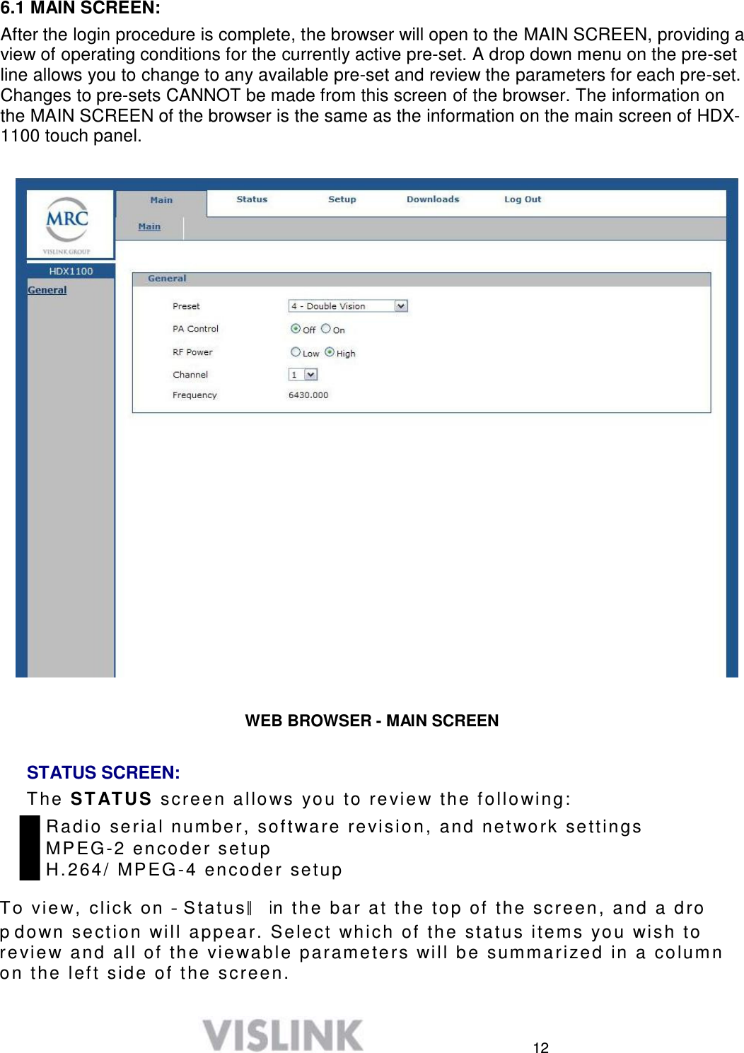
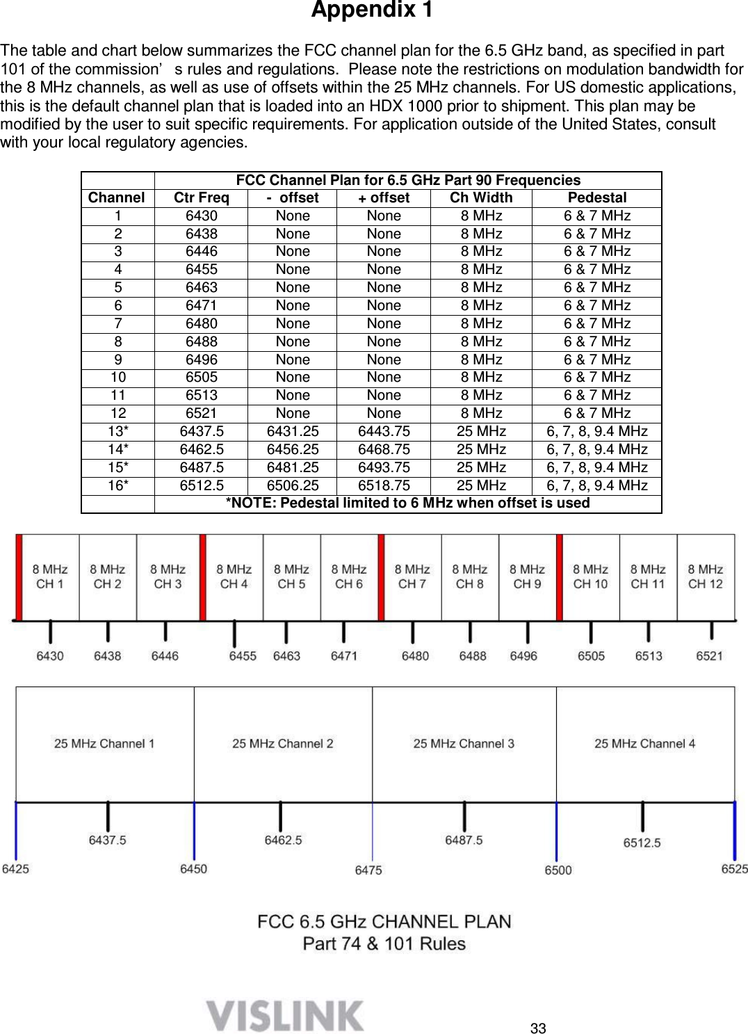
![2 2 Operating in Safety Guidelines for safe operation are derived from OET bulletin 65, August 1997, as recommended by the Federal Communications Commission (FCC). WARNING High levels of RF power are present in the unit. Exposure to RF or microwave power can cause burns and may be harmful to health. Remove power from the unit before disconnecting any RF cables and before inspecting damaged cables and/or antennas. Avoid standing in front of high gain antennas (such as a dish antenna) and never look into the open end of a waveguide or cable where RF power may be present. The HDX-1100, operated without an antenna will not create RF energy exceeding 1.0 mW/cm2, the FCC limit for exposure. Connecting an antenna to the unit greatly enhances the potential for harmful exposure, and you must maintain a certain distance from the radiator. The following table shows the Maximum Permissible Exposure (MPE) safe distances from the antenna. Antenna Gain (dB1) 0 2 3 5 11 Safe Distance (cm) 28 36 39 50 100 Safe Distance (in) 11.02 14.17 15.35 19.69 39.37 Note Hazardous RF radiation limits and recommended distances may vary by country. Observe all applicable state and federal regulations when using this transmitter. To perform calculations to understand the safe exposure margin (MPE), use the following formula suggested by OET 65. The calculations provided are for common antennas often used in the mobile microwave environment. Calculating MPE EIRP = P * (10 ^ (G / 10)) = (antilog of G/10) * P P = RF power delivered to the antenna in mW G = Power gain of the antenna in the direction of interest relative to an isotropic radiator R = distance to the center of radiation of the antenna in centimeters S = MPE in mW/cm² (milliwatts per square centimeters) Conversions dBi to numeric gain = Antilog (dBi/10) Feet to centimeters = Feet * 30.48 Centimeters to Feet = cm * .0328 4 π = 12.57 User Input RF power delivered to the antenna = Watts Antenna gain (referenced to isotropic antenna) = dBi Distance from the center of radiation = Feet Calculation steps: 1. [P] RF power input. Watts to milliwatts = Watts * 1000 2. [G] Antenna gain dBi. Numeric gain = Antilog (dBi/10) 3. [EIRP] Multiply P * G](https://usermanual.wiki/Microwave-Radio-Communications/HDX2025D.Test-report-modified-to-reflect-changes-requested-in-email-dated-3-22-213/User-Guide-1963411-Page-4.png)
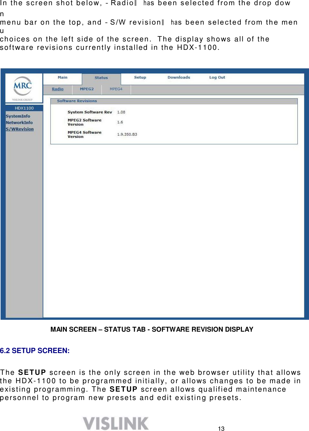
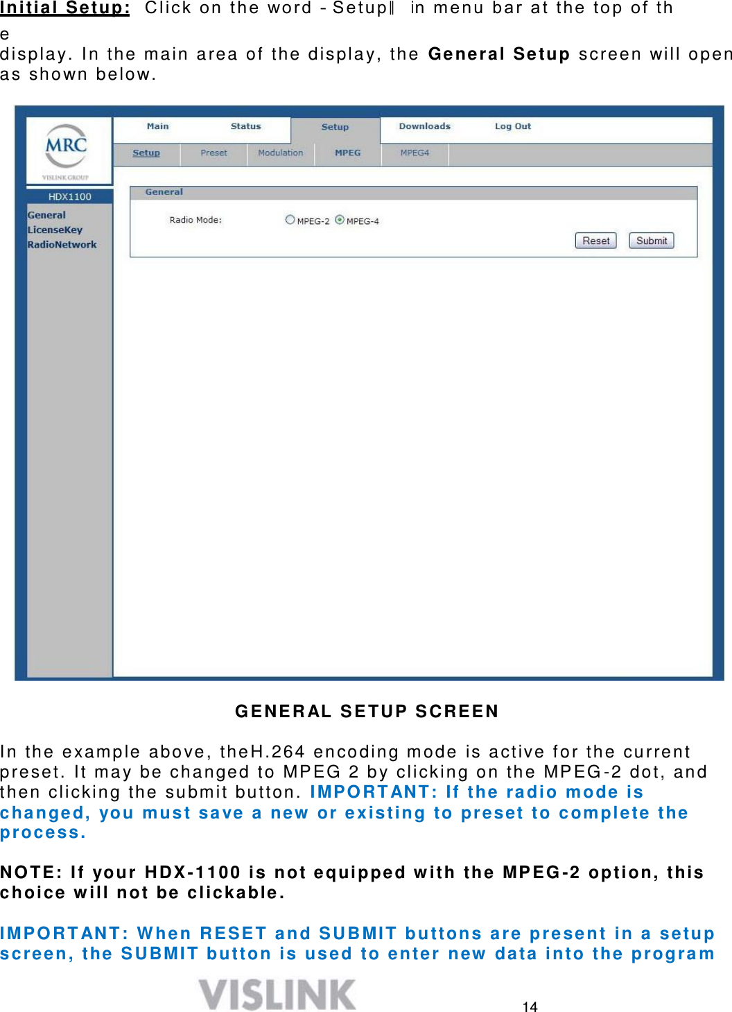
![3 4. [R] Centimeters to feet = Centimeters * .0328 5. Square R 6. Multiply R² * 4π 7. [S] Divide (R² * 4π ) into EIRP S = Power Density in milliwatts per square centimeters. Note At frequencies above 1500 MHz, S must not be greater than 1. Reference FCC OET Bulletin 65, August 1997 - Evaluating Compliance with FCC Guidelines for Human Exposure to Radio Frequency Electromagnetic Fields Vislink, in accordance with the requirements set forth by the FCC, provides this information as a guide to the user and assumes the users of this equipment are licensed and qualified to operate the equipment per the guidelines and recommendations contained within the product user guides and in accordance with any FCC rules that may apply.](https://usermanual.wiki/Microwave-Radio-Communications/HDX2025D.Test-report-modified-to-reflect-changes-requested-in-email-dated-3-22-213/User-Guide-1963411-Page-5.png)