Mitel Networks RFP47DRC DECT base station User Manual SIP DECT OM System Manual EN 8 0 2018 09 28
Mitel Networks DECT base station SIP DECT OM System Manual EN 8 0 2018 09 28
UserManual.wiki
>
Mitel Networks
>
RFP47DRC User Manual
>
User Manual I
Contents
1.
User Manual I
2.
User Manual II
User Manual I
Navigation menu
Upload a User Manual
Namespaces
Wiki Guide
HTML
PDF
Info
Views
User Manual
Discussion / Help
Navigation

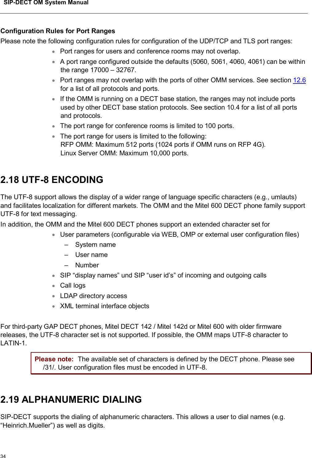
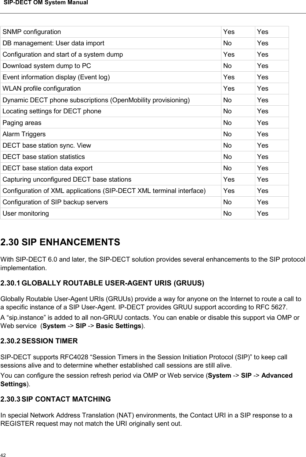
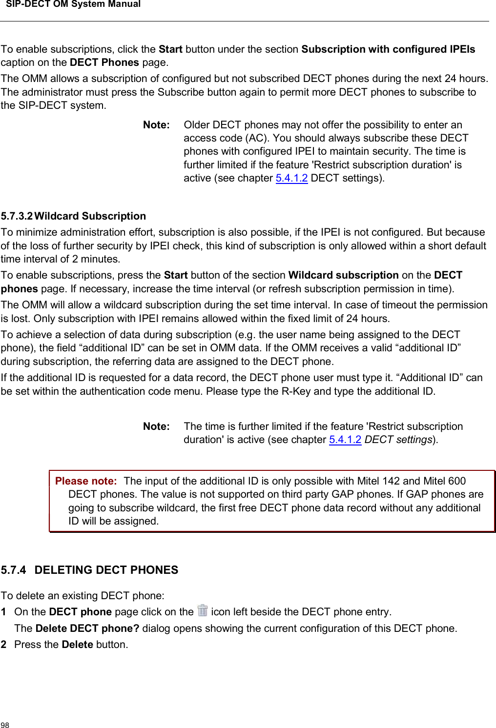
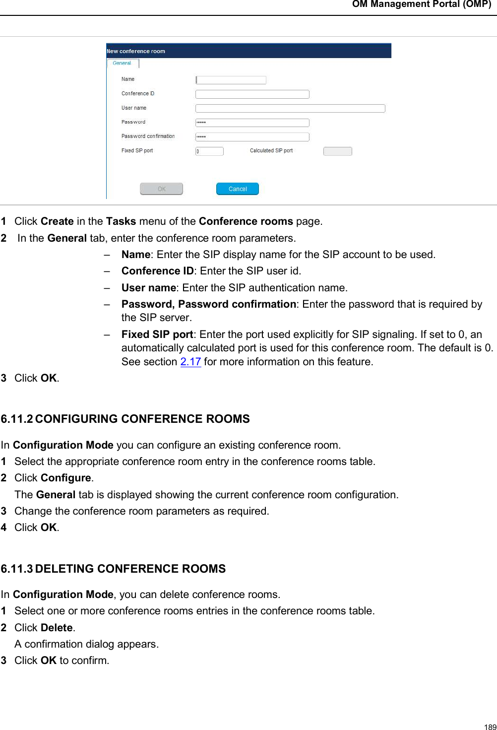
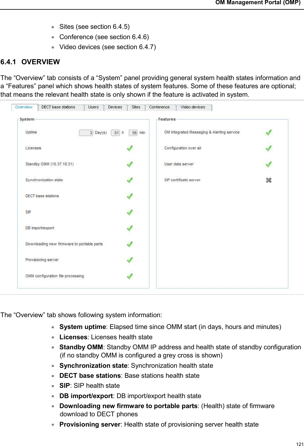
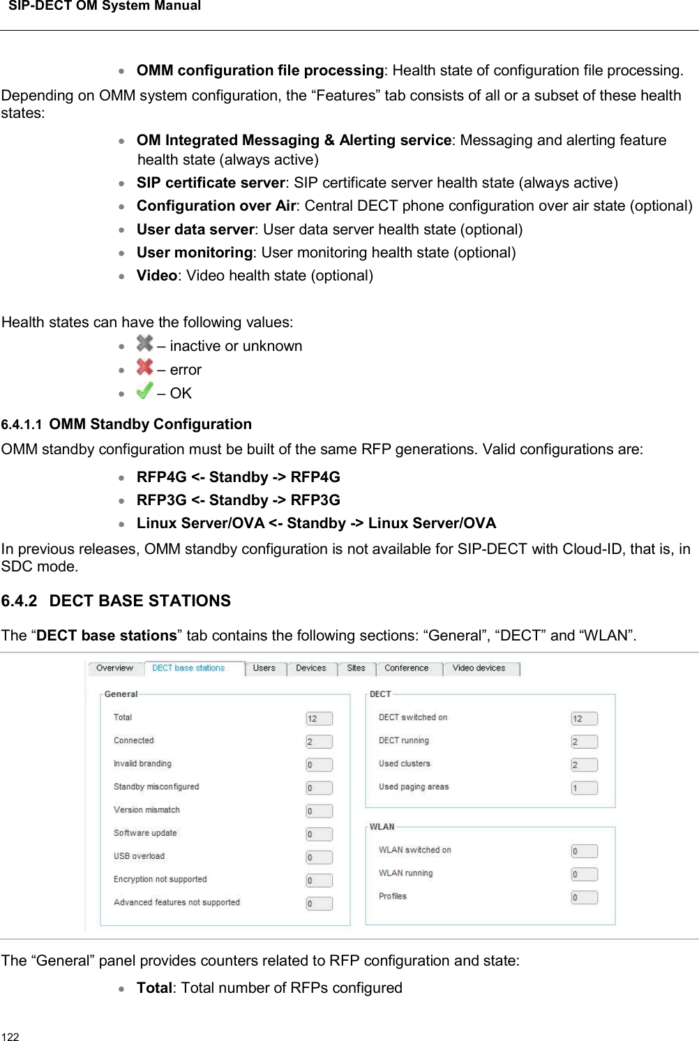
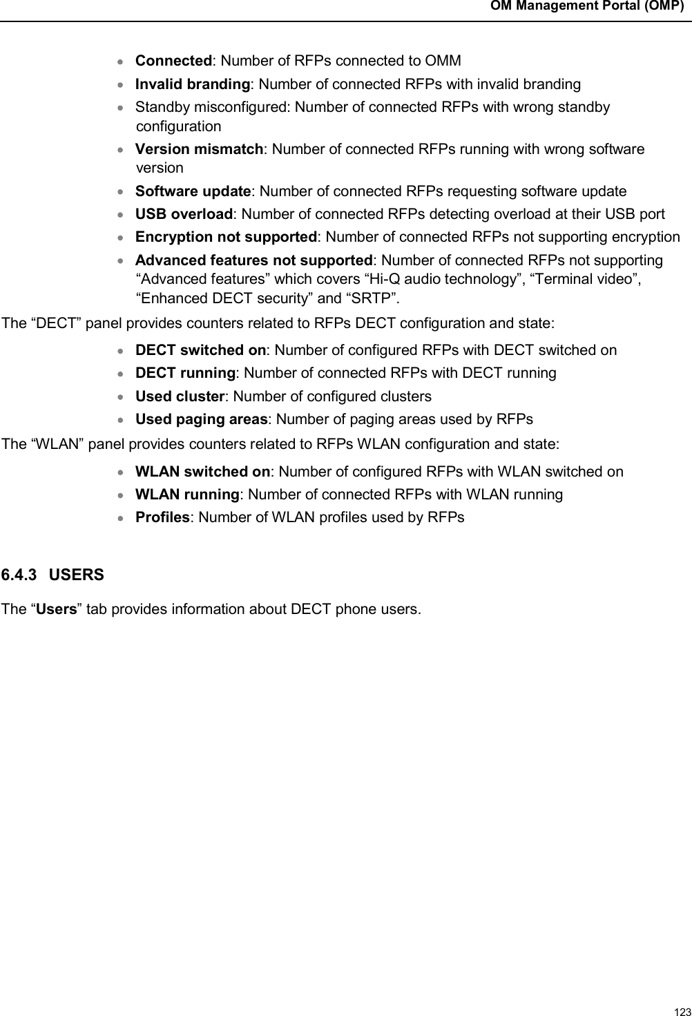
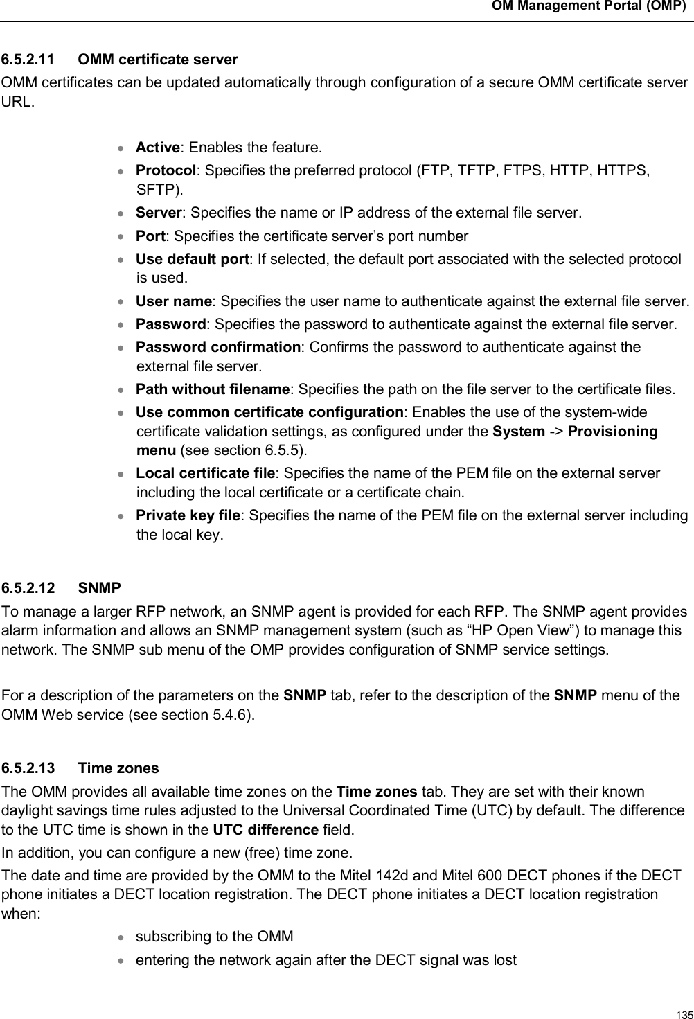
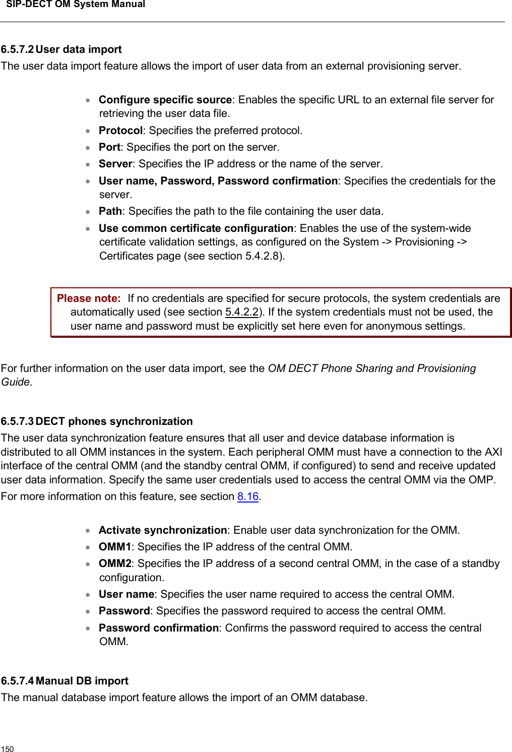
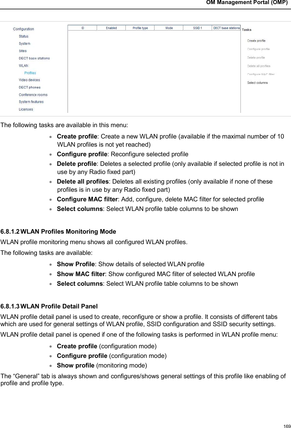
![SIP-DECT OM System Manual104You can: create and change WLAN profiles (see section 5.8.1.1)delete WLAN profiles (see section 5.8.1.2)export WLAN profiles (see section 5.8.1.3)The defined WLAN profiles are then assigned to one or more WLAN base stations (see section 5.8.2). Note, that some device-specific WLAN settings are not part of a WLAN profile, such as the channel and the antenna configuration. These settings are defined separately for each base station (see section5.6.3).5.8.1.1Creating and Changing WLAN ProfilesYou need at least one active WLAN profile in order to operate the WLAN function for an RFP 42/43/48 WLAN device.1Navigate to the WLAN profiles page. This page shows the number of existing WLAN profiles and a list of available WLAN profiles.2If you create a new WLAN profile, configure the RFP type first to get the correct input fields. Select the appropriate profile (RFP 42, RFP 43 or RFP 48) from the WLAN profile type selection list. 3To add a new WLAN profile, press the New button. To change an existing WLAN profile, click on the icon available on the left of the WLAN profile entry.The New WLAN profile page resp. the WLAN profile [Number] page shows the WLAN profile configuration.4Change the desired settings of the WLAN profile. You need at last to define the ESSID setting. The different settings are explained in detail in the sections below.5Activate the Profile active setting; otherwise the WLAN profile is inactive which de-activates the WLAN function for base stations that are assigned to this WLAN profile.6Press the OK button to apply the settings. If you created a new WLAN profile, you can proceed by assigning the WLAN profile to the desired base stations (see section 5.6.3). If you changed an existing WLAN profile, the settings are applied to the assigned base stations automatically. The following parameters are available on the New WLAN profile page and on the WLAN profile [Number] page:General settingsProfile active: Activate this checkbox to activate the profile. This in turn activates the WLAN function for all RFPs that are assigned to the WLAN profile.](https://usermanual.wiki/Mitel-Networks/RFP47DRC.User-Manual-I/User-Guide-4037306-Page-104.png)
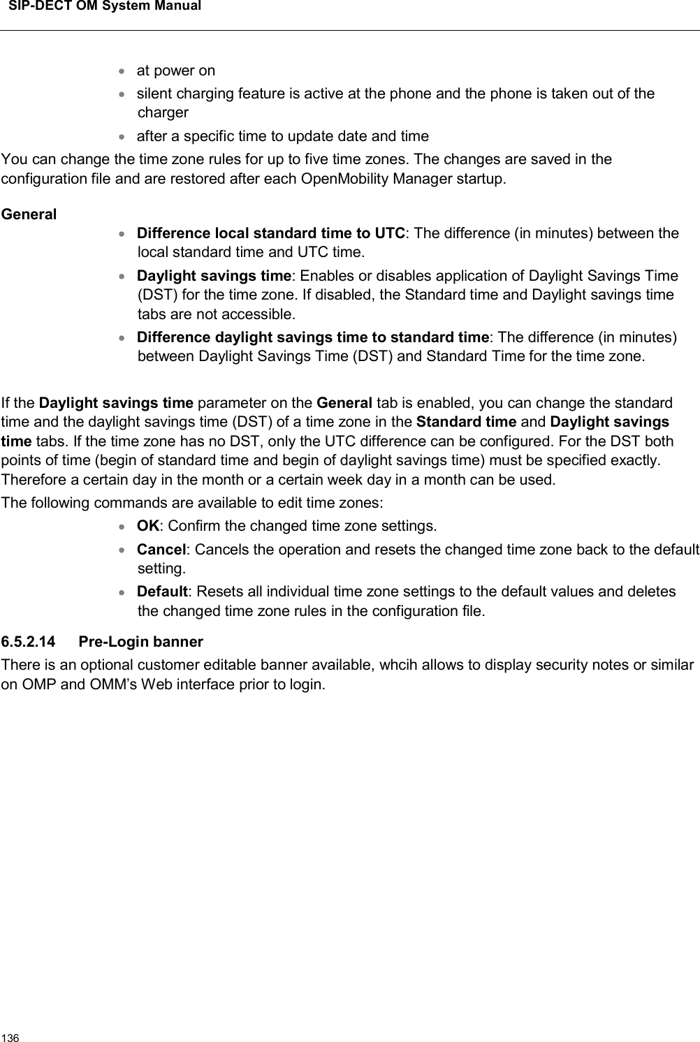
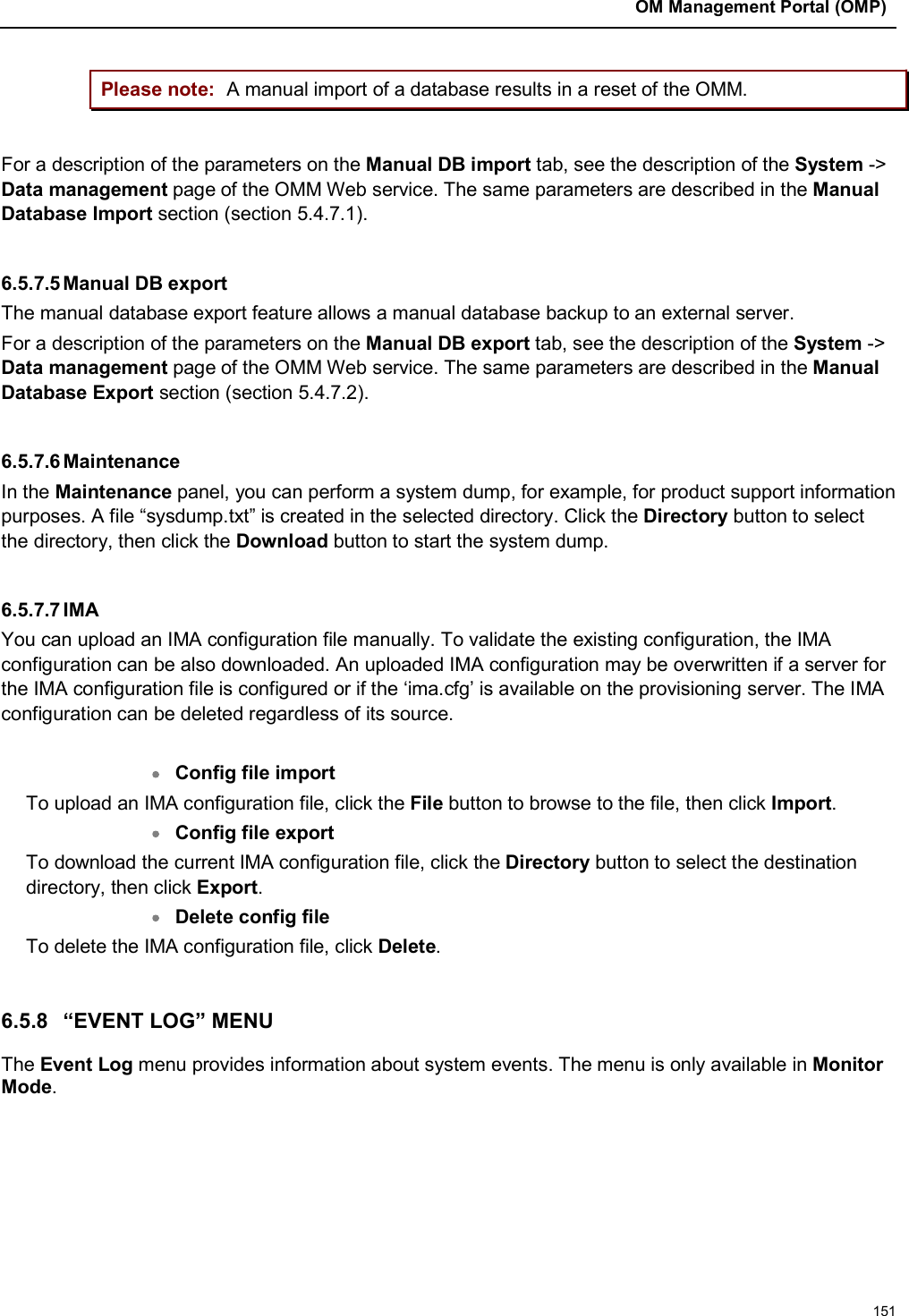
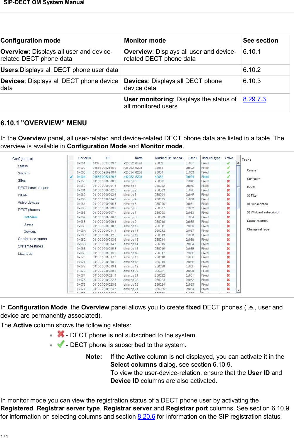
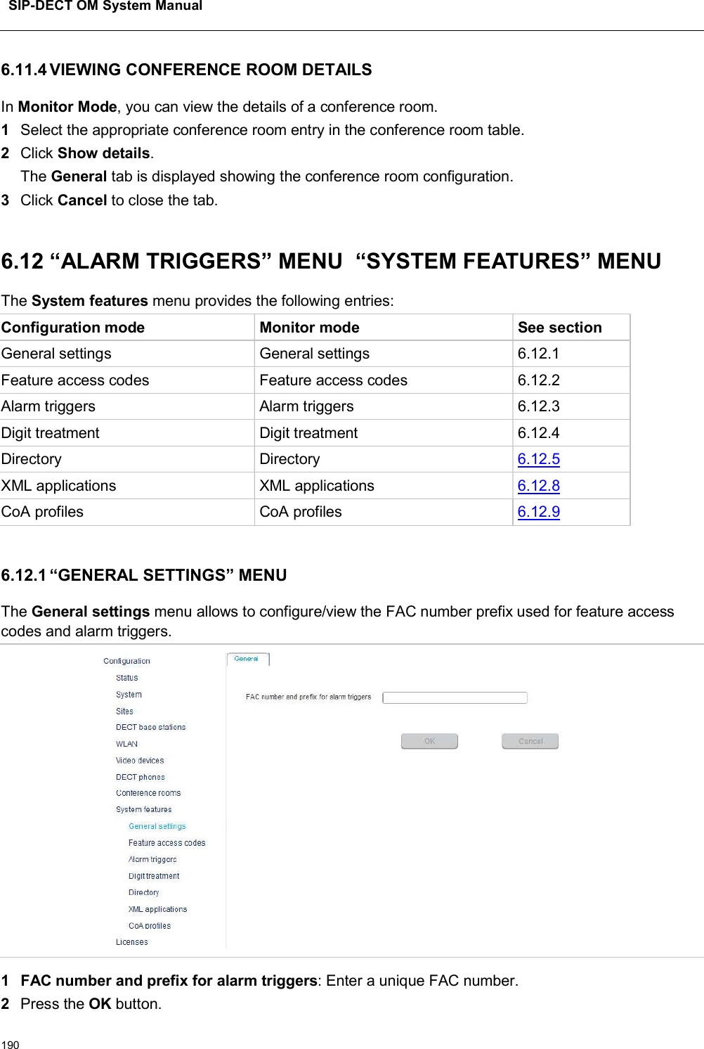
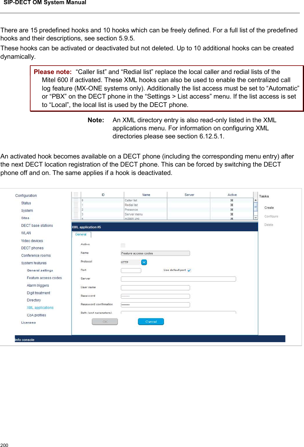
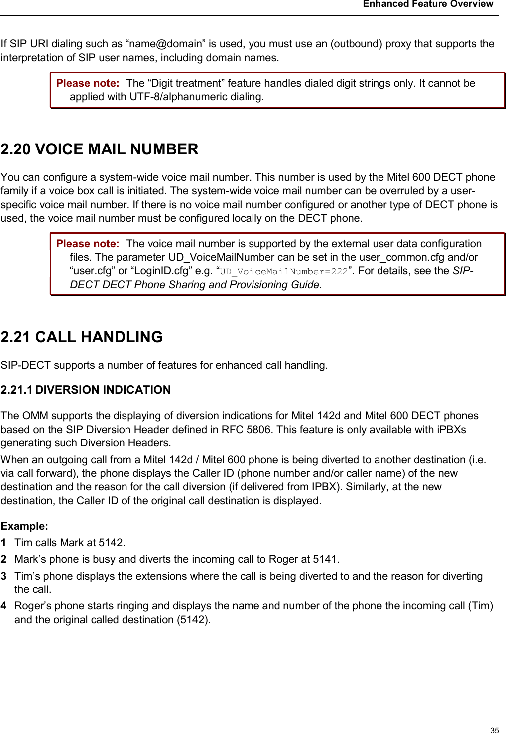
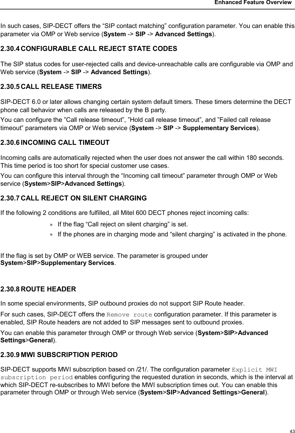
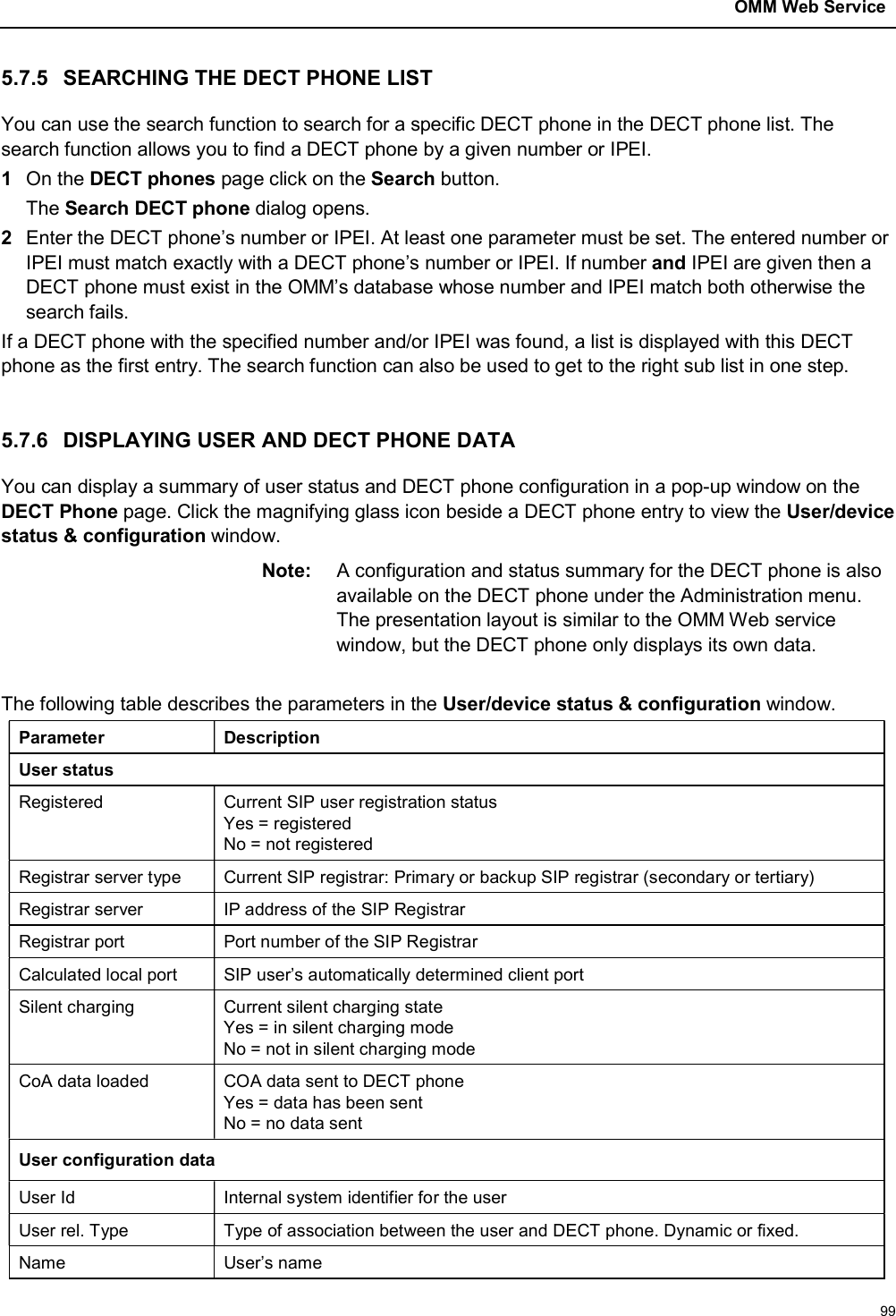
![SIP-DECT OM System Manual186– In the Overview submenu the whole DECT phone dataset will be deleted. – In the Users submenu only the DECT phone user data will be deleted.– In the Devices submenu only the DECT phone device data will be deleted.The Delete [xxx] dialog opens showing a confirmation prompt.3Confirm the displayed prompt with OK.6.10.9 SELECTING COLUMNSYou can adapt the parameters shown in the DECT phone table to your needs:1Click Select columns under the Task list on the right-hand side of the DECT Phones window. The Select columns dialog opens. 2Select the columns that shall be shown by activating the appropriate checkboxes.3Click the OK button.4The DECT phone table will be adapted accordingly. 6.10.10 FILTERING DECT PHONE TABLEYou can filter the list of DECT phone datasets shown in the DECT phone table by using a filter.1Click Filter under the Task list on the right-hand side of the DECT Phones window.The Filter dialog opens. 2Enter the search string that serves as filter criterion. You can enter digits and characters. The search is case sensitive. 3Click on the Filter button.The Filter dialog is closed and the DECT phone table will be adapted accordingly.4To reset the filter, click on the Filter command in the task bar on the right of the DECT phones panel. 5In the Filter dialog click on the Reset button. 6.10.11 CHANGING THE RELATION TYPEYou can change a user data-device relation data set from “fixed” to “dynamic” and vice versa. This means the login/logout feature can be enabled or disabled for a DECT phone. The user data device relation can only be changed by the admin user.To change the relation type of a DECT phone:1Select the appropriate DECT phone dataset(s) in the DECT phone table by activating the corresponding checkbox(es).2Click Change rel. type under the Task list on the right-hand side of the DECT Phones window.Rules to change the relation from “fixed” to “dynamic”The DECT phone must be subscribed.A user login/logout PIN is configured in the user data set.](https://usermanual.wiki/Mitel-Networks/RFP47DRC.User-Manual-I/User-Guide-4037306-Page-186.png)