Motorola Solutions 89FT5863 PORTABLE MULTIBAND 2-WAY RADIO User Manual APX 6000 M1 5 Portable Radio User Guide
Motorola Solutions, Inc. PORTABLE MULTIBAND 2-WAY RADIO APX 6000 M1 5 Portable Radio User Guide
Contents
- 1. Users Guide
- 2. RF Safety Guide
- 3. User Manual
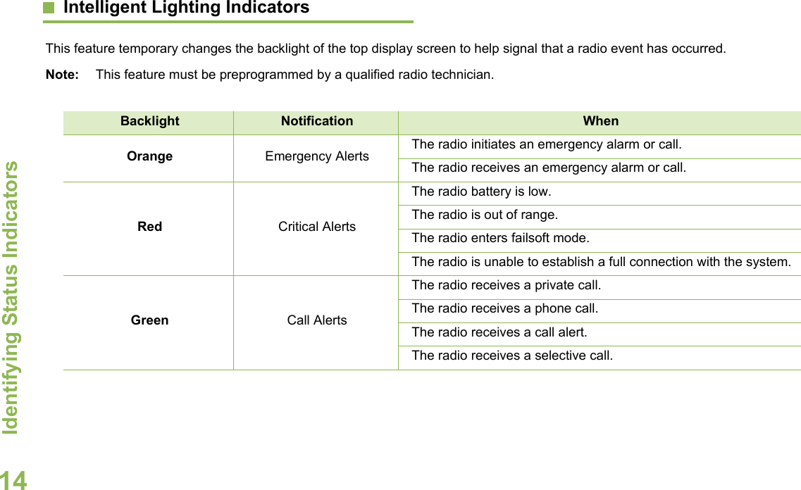
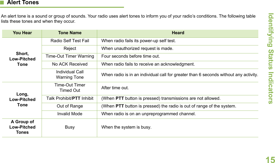
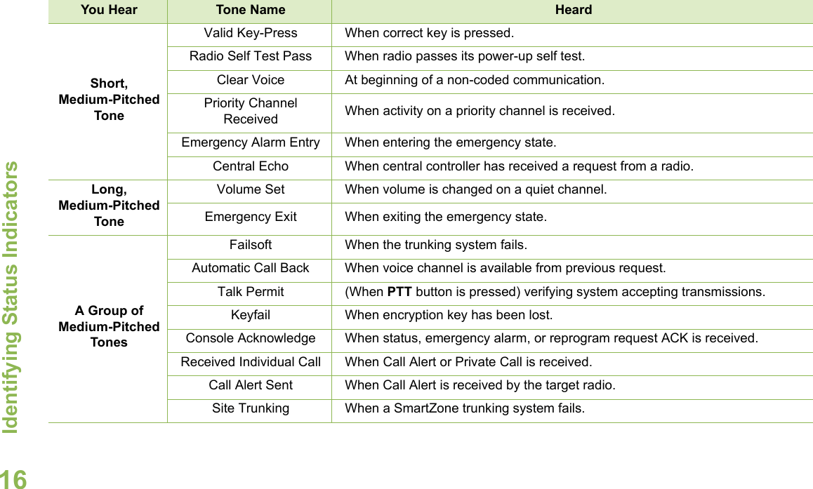
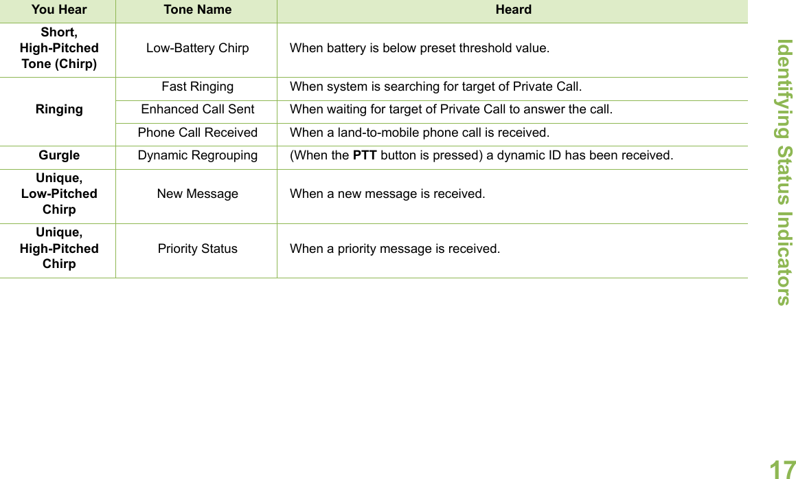
Users Guide