Motorola Solutions 89FT5863 2-way portable radio with BlueTooth User Manual MN000350A02
Motorola Solutions, Inc. 2-way portable radio with BlueTooth MN000350A02
UserManual.wiki
>
Motorola Solutions
>
89FT5863 User Manual
>
User Manual
Contents
1.
Users Guide
2.
RF Safety Guide
3.
User Manual
User Manual
Navigation menu
Upload a User Manual
Namespaces
Wiki Guide
HTML
PDF
Info
Views
User Manual
Discussion / Help
Navigation

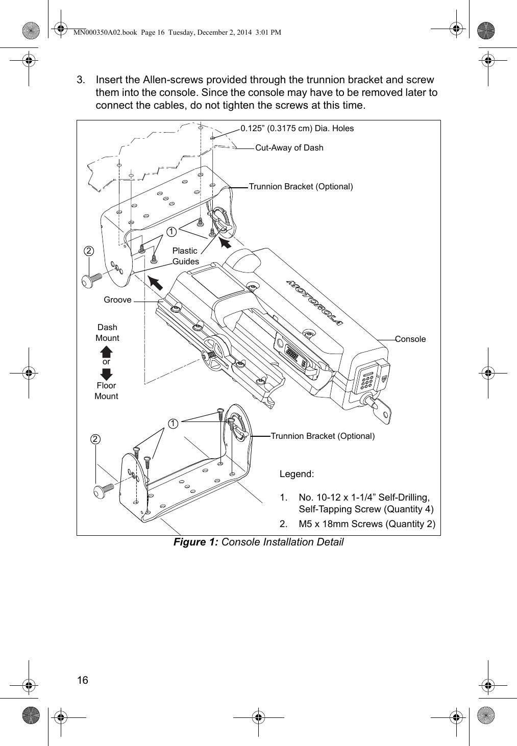
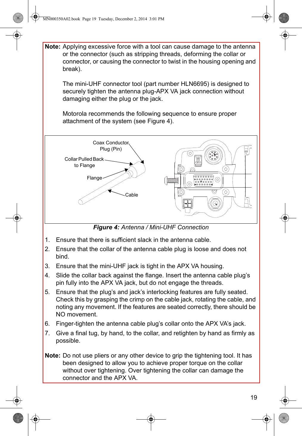
![18Mounting restrictions for certain radio models:a. For all VHF and UHF models, the 1/4 wave antenna should be mounted only in the center area of the roof, not on the trunk lid, to ensure compliance with RF Energy Safety Standards.b. Ensure that the antenna cable can be easily routed to the APX VA. Route the antenna cable as far away as possible from any vehicle electronic control units and associated wiring.c. Check that the antenna location for any electrical interference.d. Ensure that any transmitting radio antennas on this vehicle are separated from each other by at least 3 feet (92 cm). See Figure 3.Figure 3: Multiple Antenna Separatione. The minimum distance between the antenna and the radio or accessories should be at least 3 feet (92 cm).Note: Any two metal pieces rubbing against each other (such as seat springs, shift levers, trunk and hood lids, exhaust pipes, and others) in close proximity to the antenna can cause severe receiver interference.Mini-UHF ConnectionNote: The RF connector (J3) on APX VA console is a mini-UHF jack, and must be mated with either an antenna mini-UHF plug (P3) or an appropriate adapter (part numbers: 5880367B21 [mini-UHF-to-N]; 5880367B22 [mini-UHF-to-UHF]; or 5880367B24 [mini-UHF-to-TNC]).To ensure a secure connection of an antenna cable’s mini-UHF plug to an APX VA mini-UHF jack, their interlocking features must be properly engaged. If they are not properly engaged, the system will loosen. Using a tool (pliers or wrench) will not overcome a poor engagement, and is not recommended.If these conditions cannot be satisfied, then mount the antenna on the roof top.MN000350A02.book Page 18 Tuesday, December 2, 2014 3:01 PM](https://usermanual.wiki/Motorola-Solutions/89FT5863.User-Manual/User-Guide-2537987-Page-20.png)