OTC Engineering S L 210M1100 Motorcycle dahsboard with Bluetooth for communications with mobile phone User Manual
OTC Engineering S.L. Motorcycle dahsboard with Bluetooth for communications with mobile phone Users Manual
UserManual.wiki
>
OTC Engineering S L
>
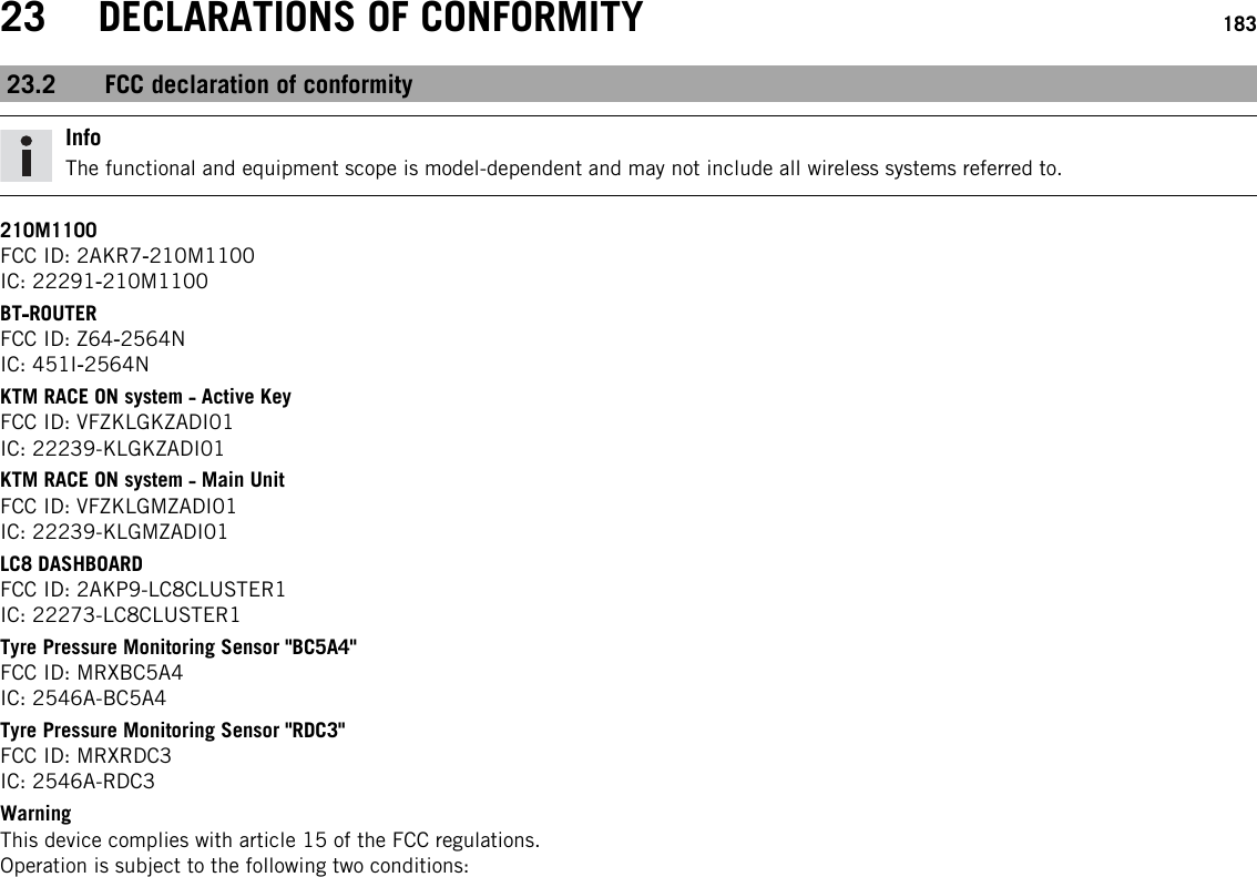
210M1100 User Manual
Users Manual
Navigation menu
Upload a User Manual
Namespaces
Wiki Guide
HTML
PDF
Info
Views
User Manual
Discussion / Help
Navigation