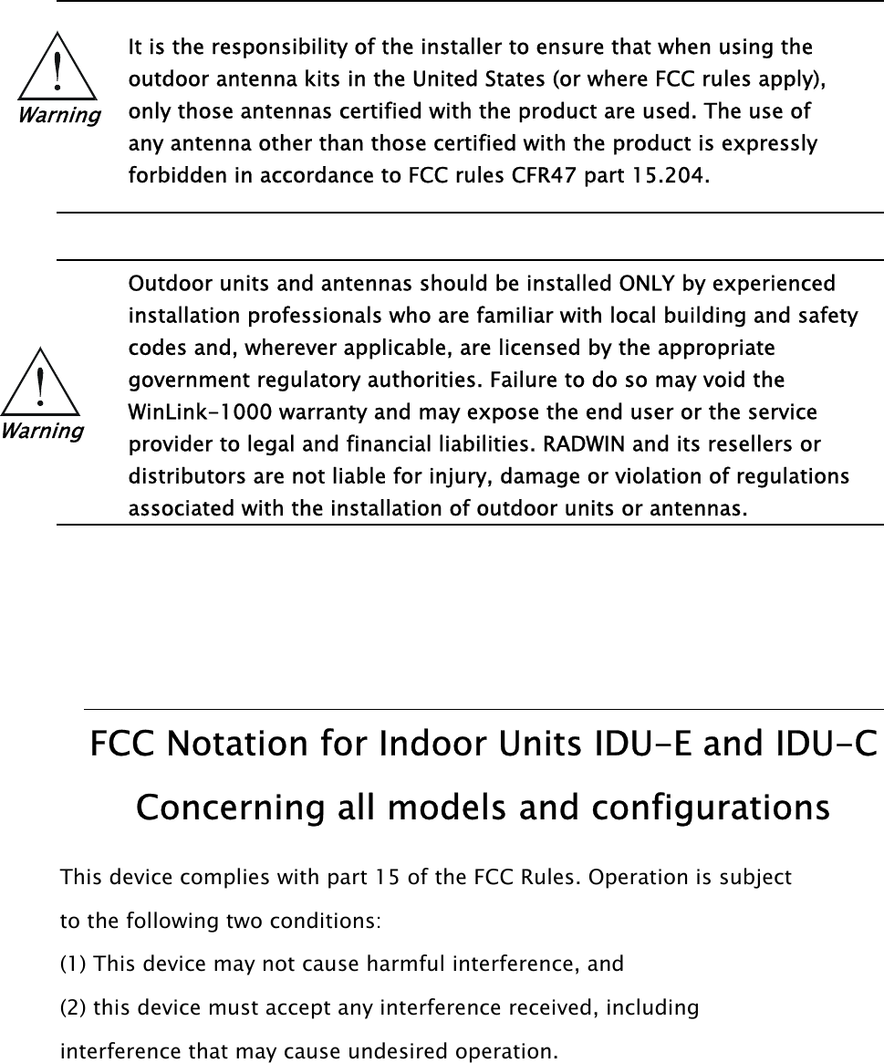
Radwin AMWL1240H ODU User Manual Part 1
Radwin Ltd. ODU Users Manual Part 1
UserManual.wiki
>
Radwin
>
AMWL1240H User Manual
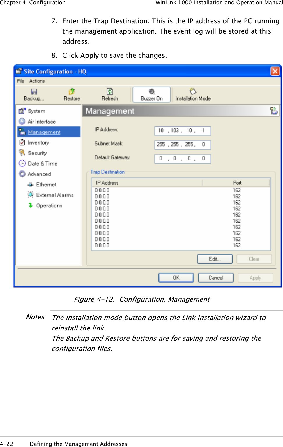
>
Users Manual Part 1
Contents
1.
Users Manual Part 1
2.
Users Manual Part 2
Users Manual Part 1
Navigation menu
Upload a User Manual
Namespaces
Wiki Guide
HTML
PDF
Info
Views
User Manual
Discussion / Help
Navigation
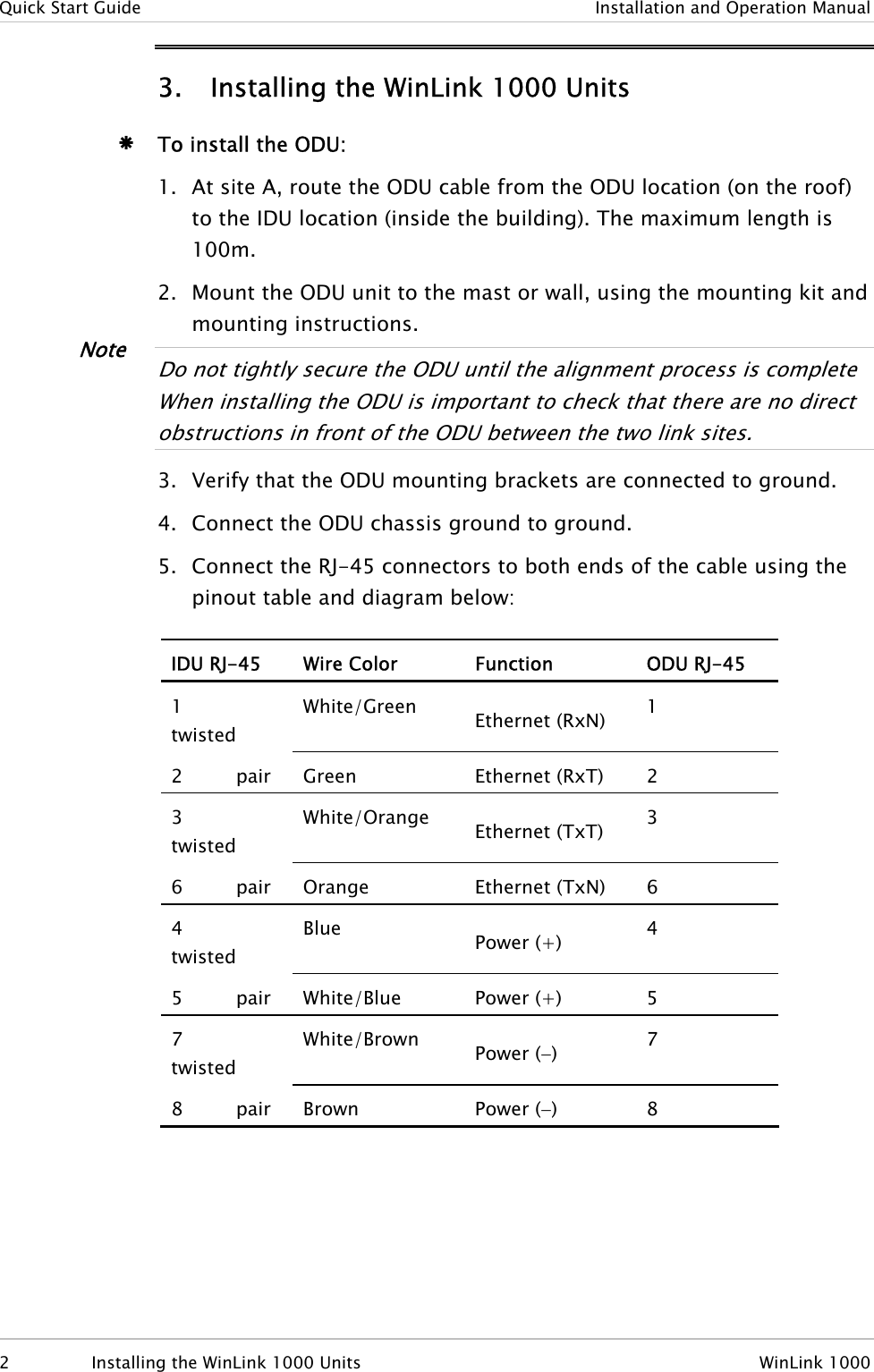
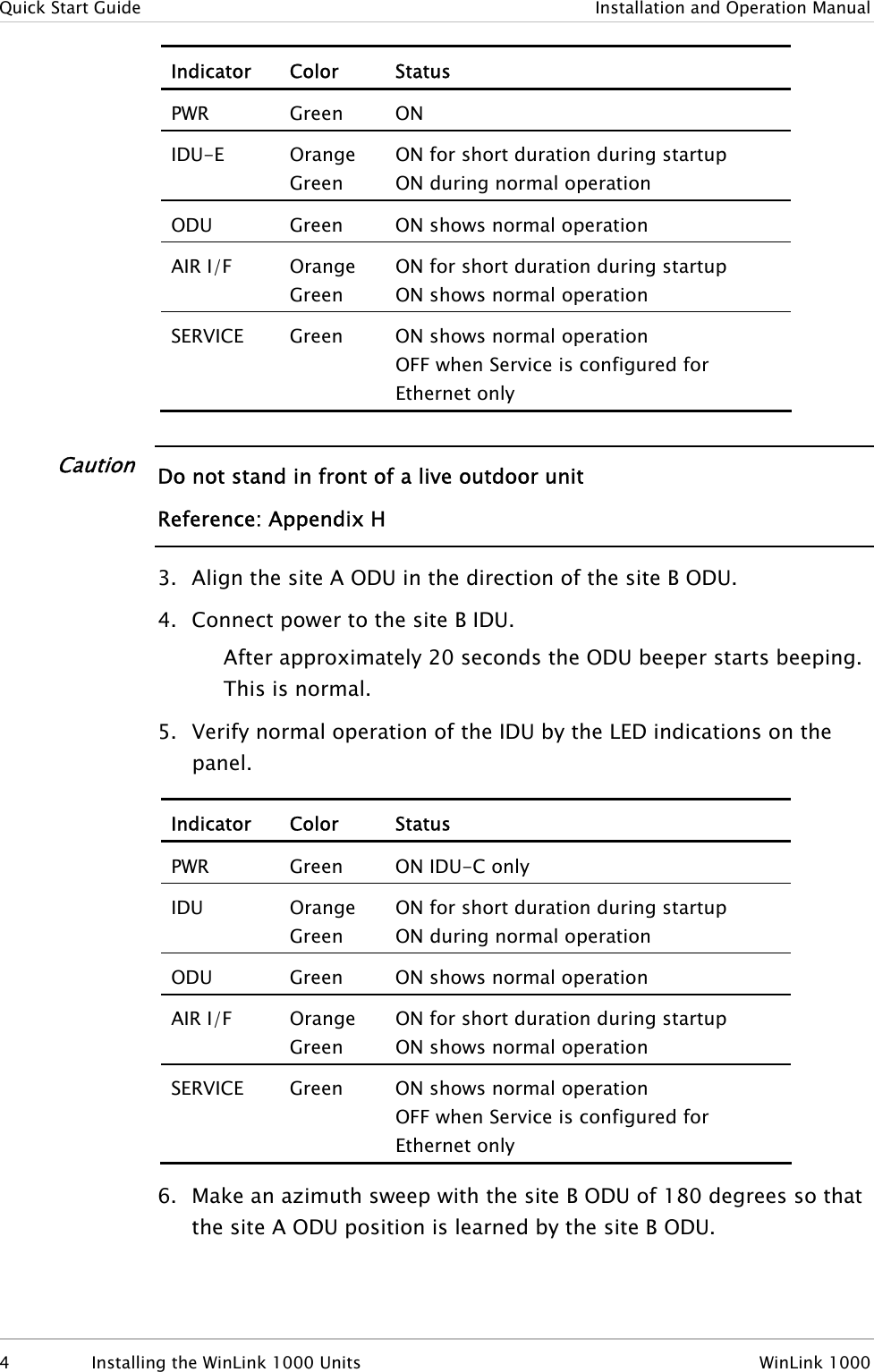
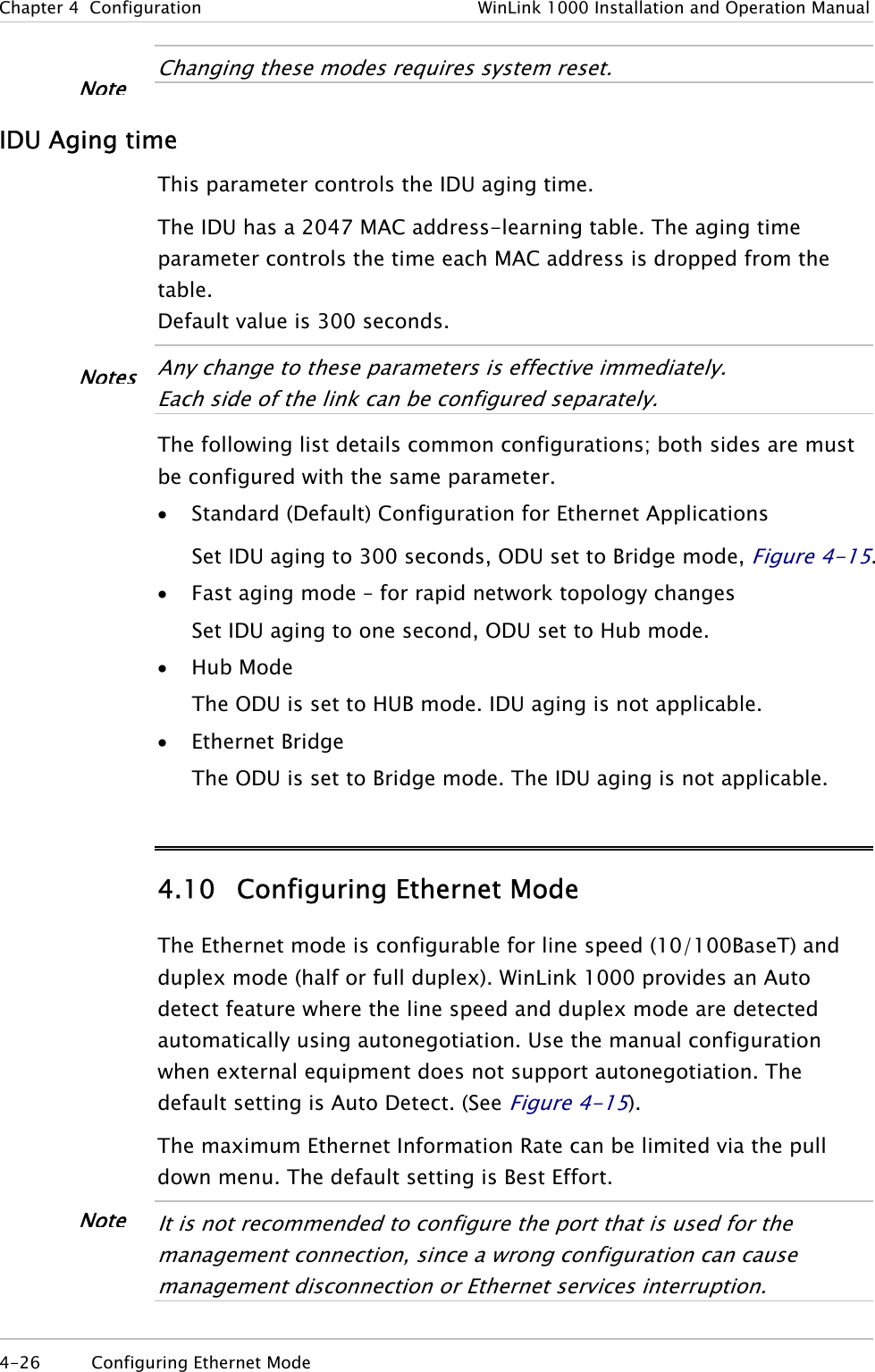
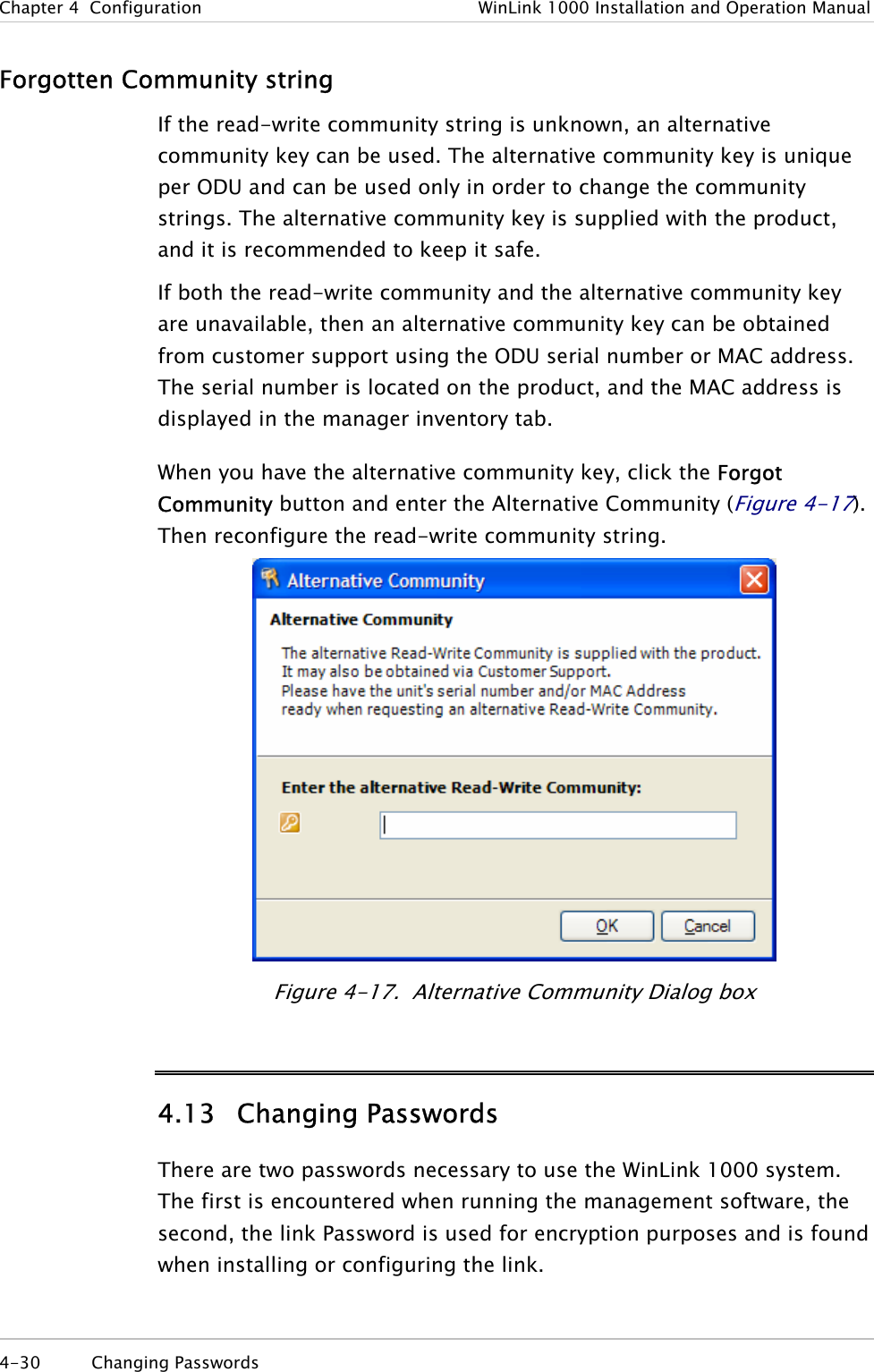
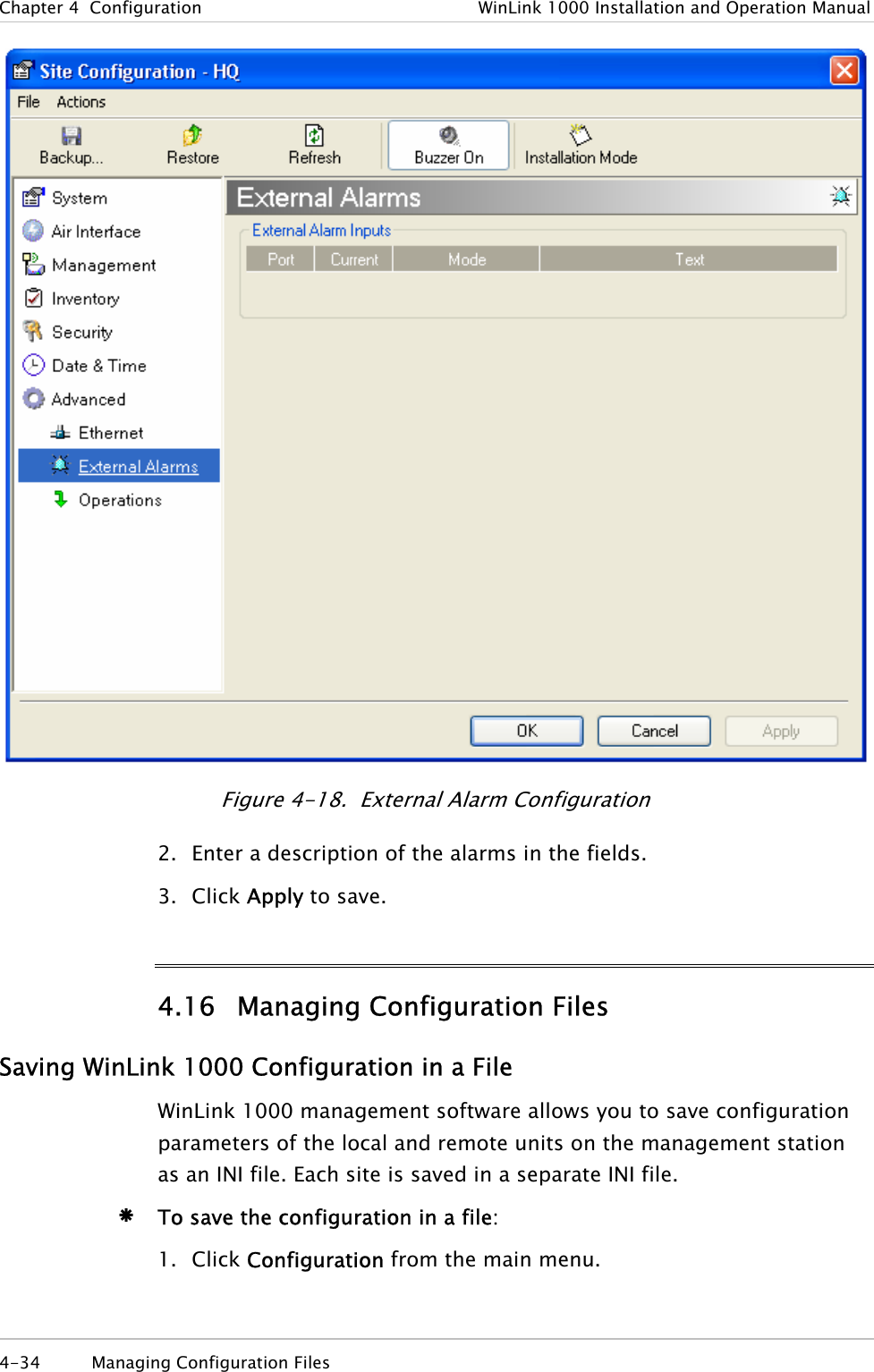
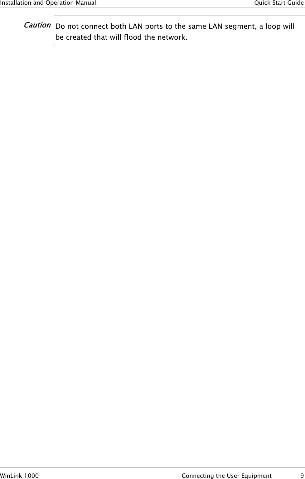
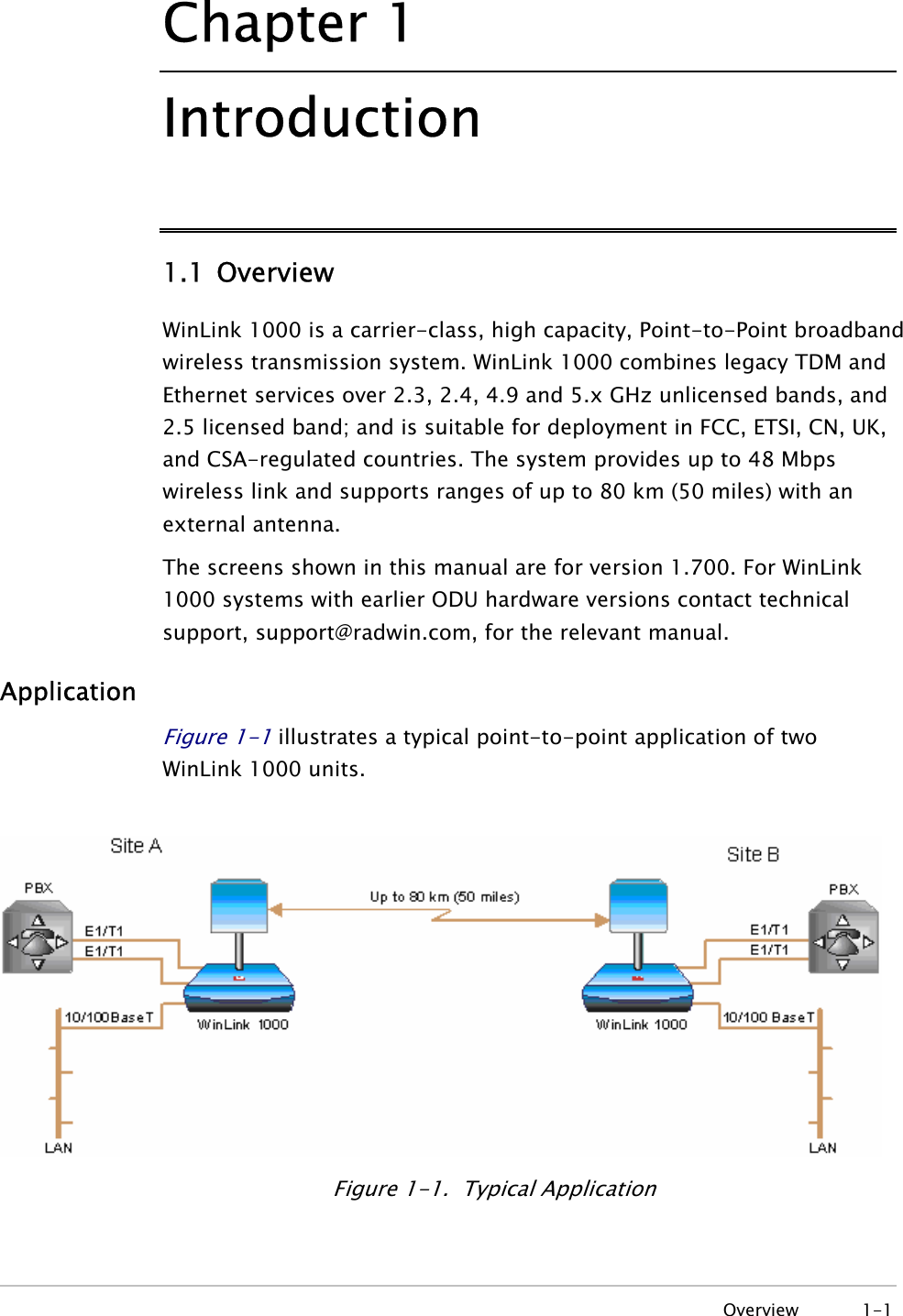
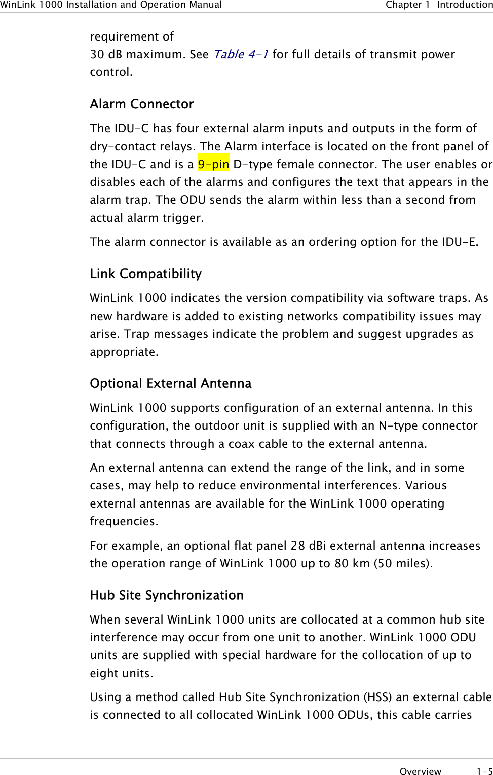
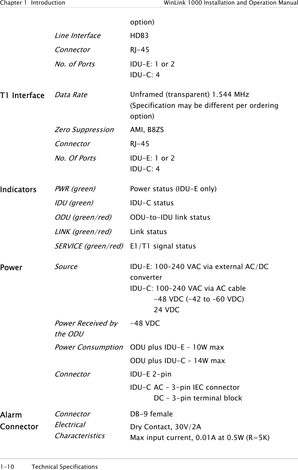
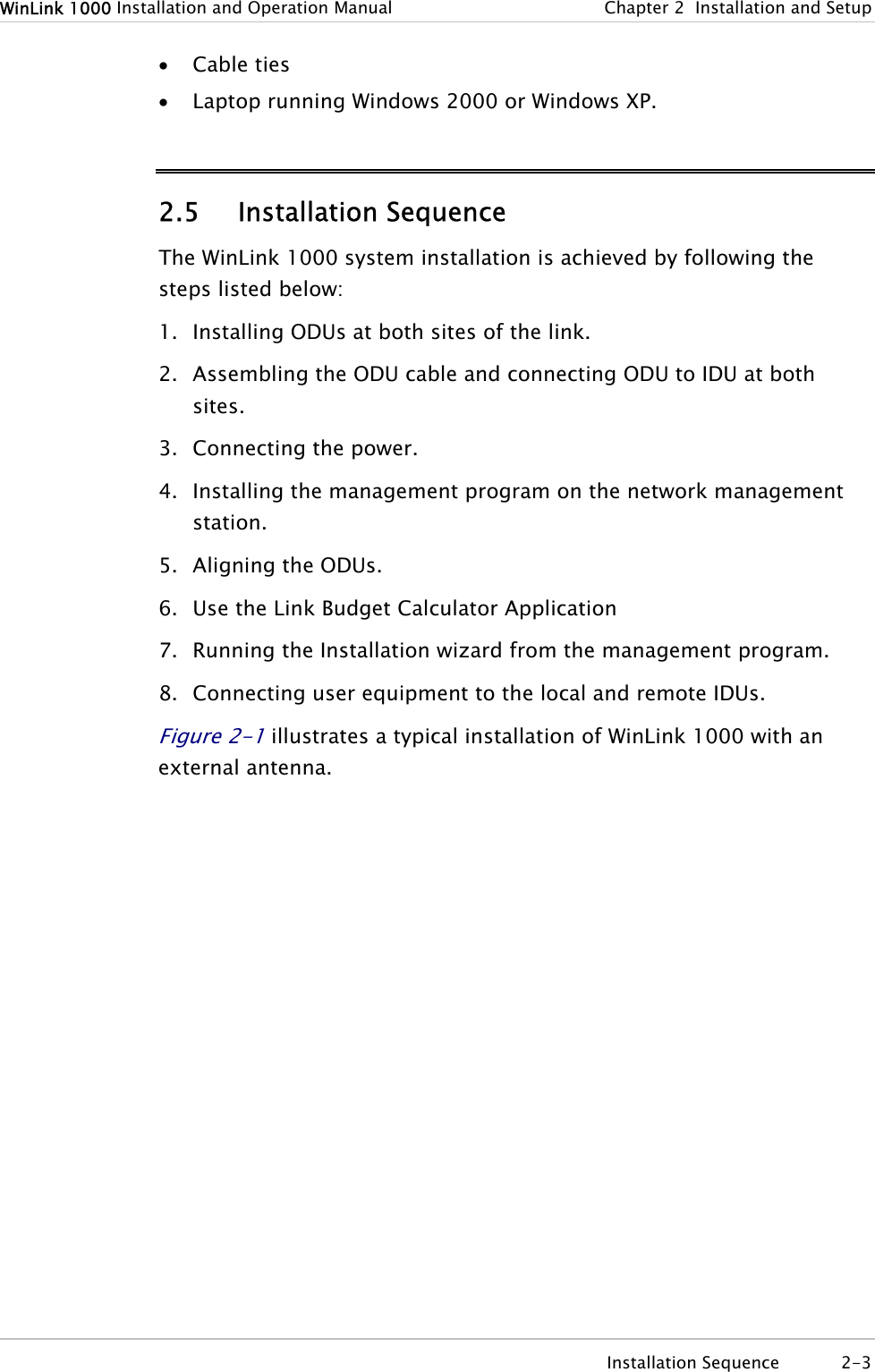
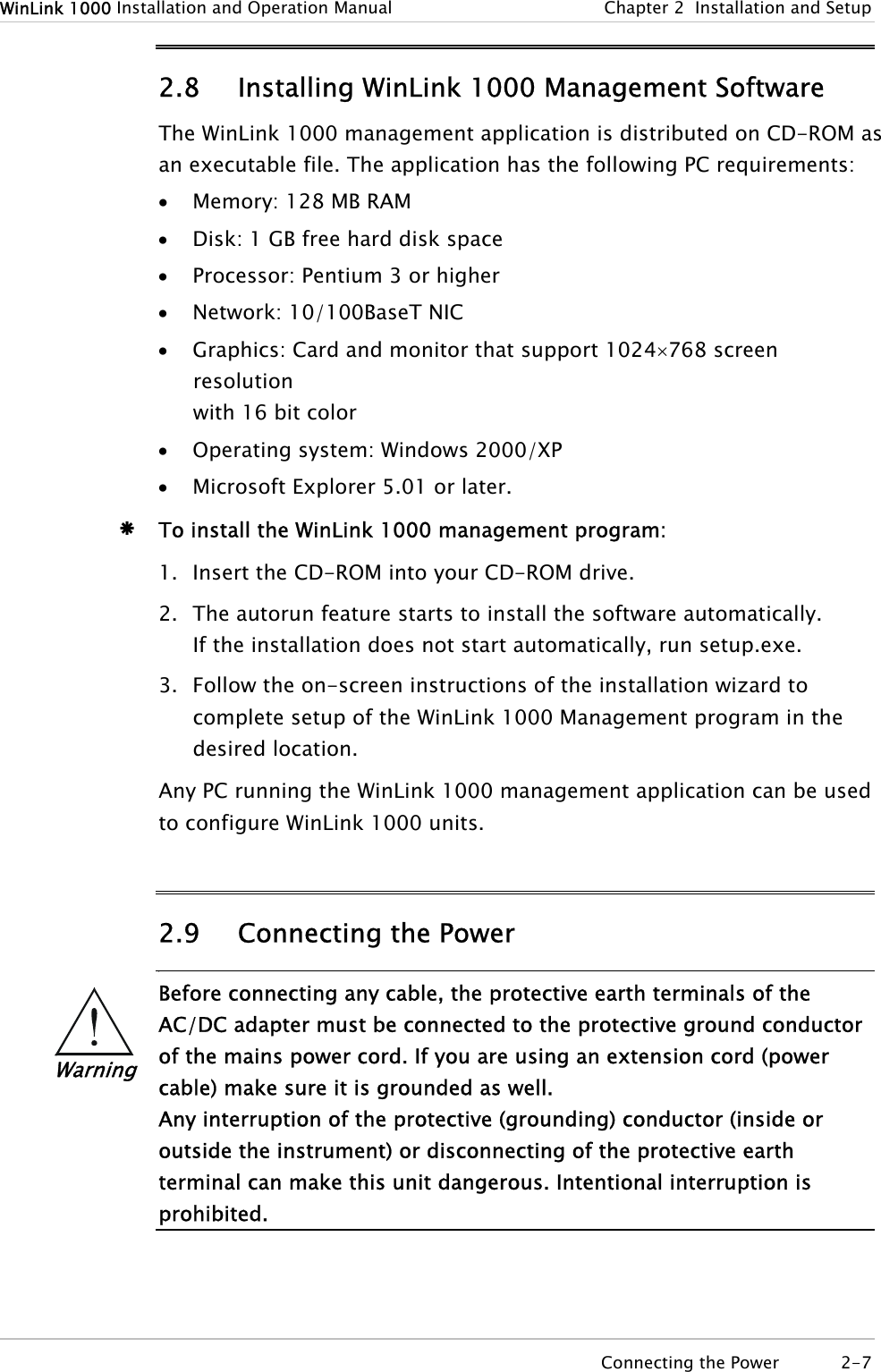
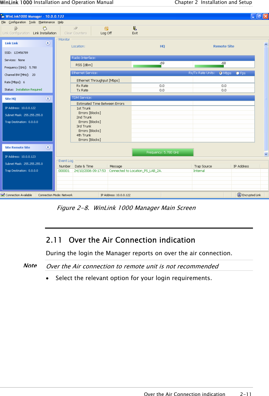
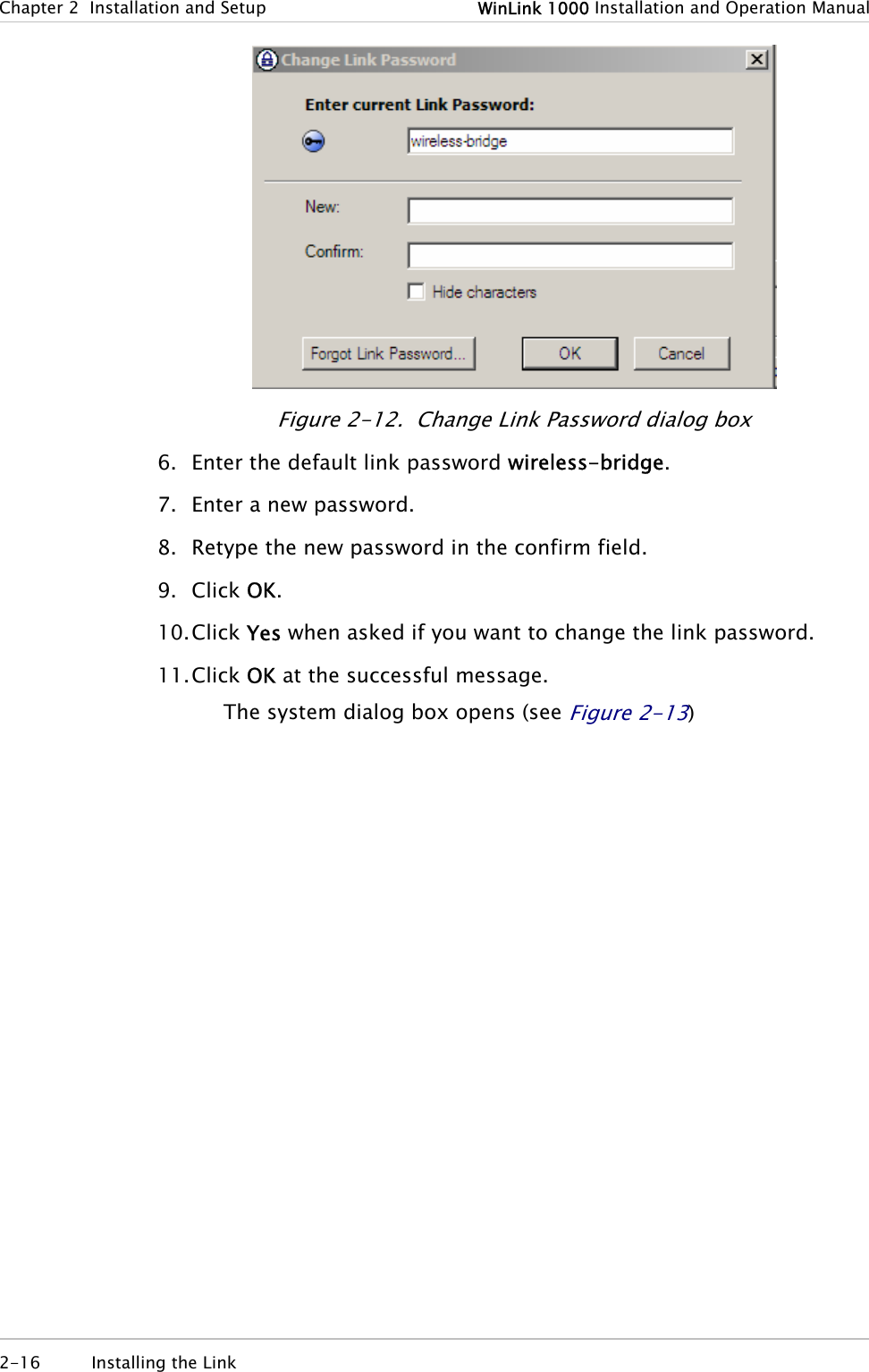
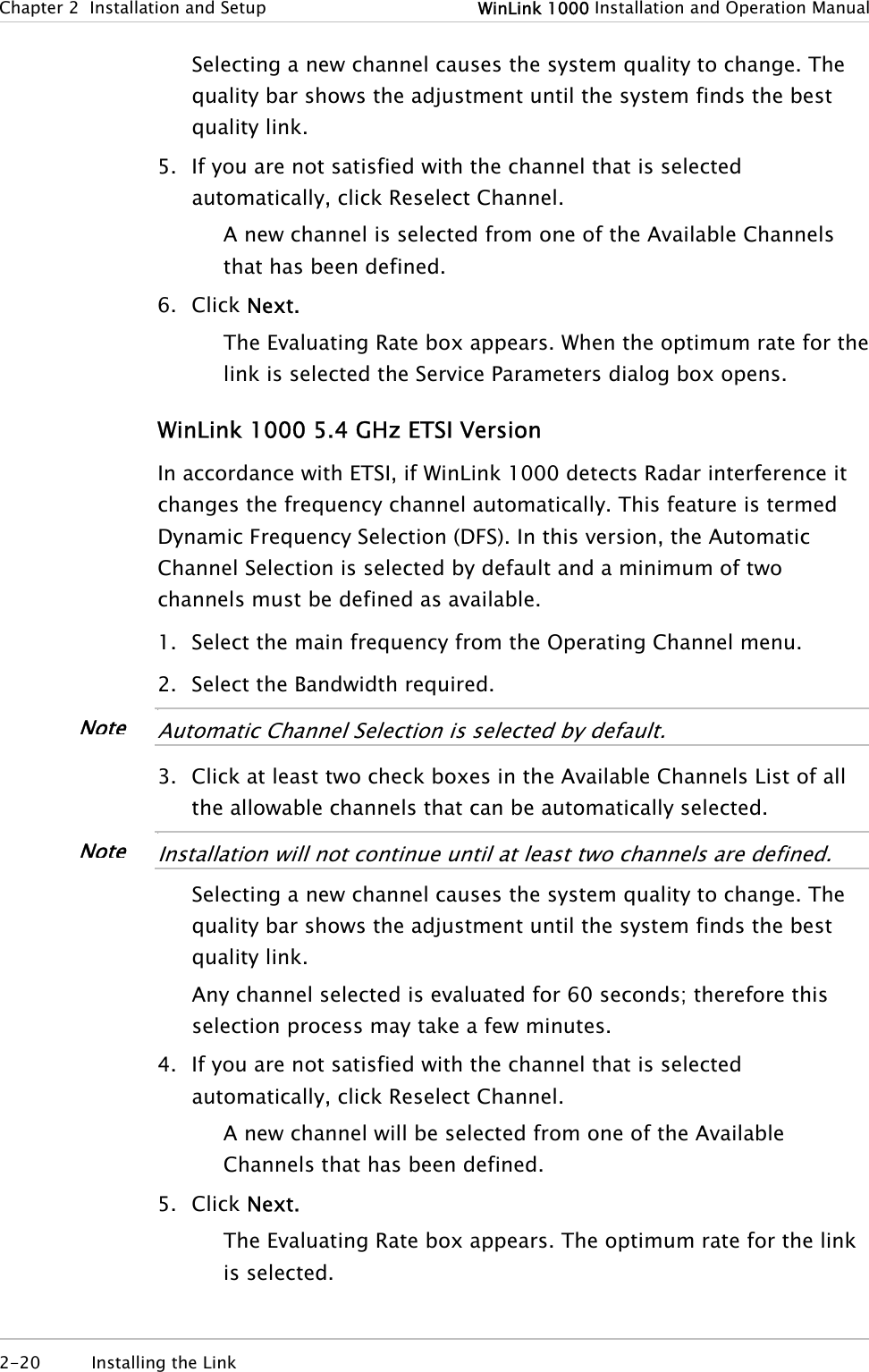
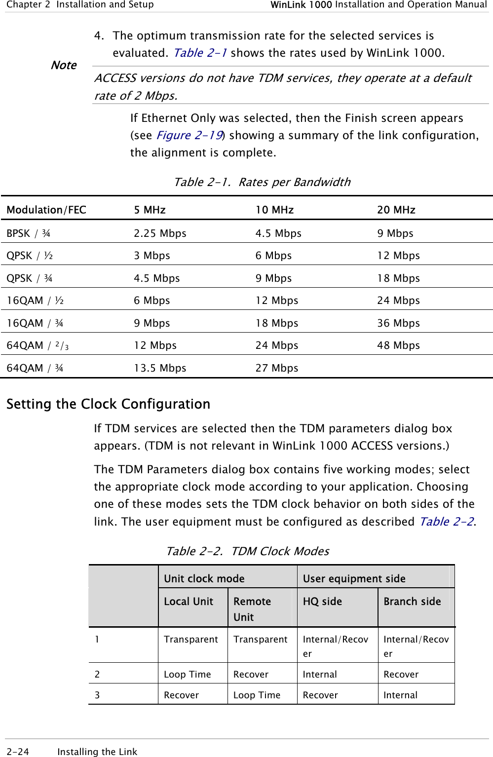
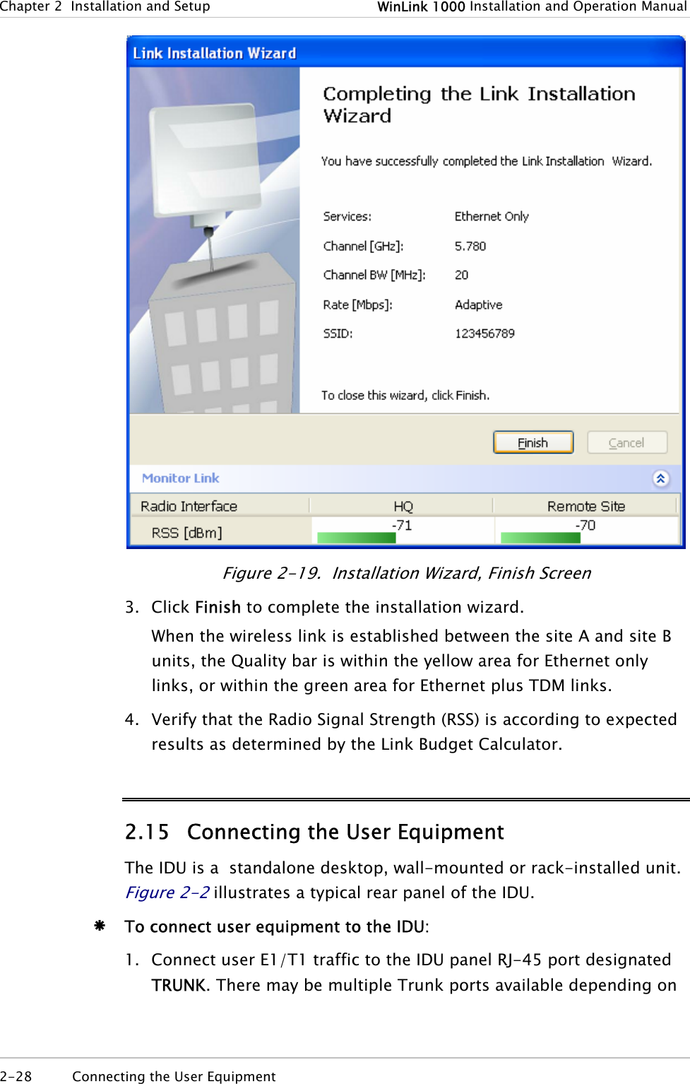
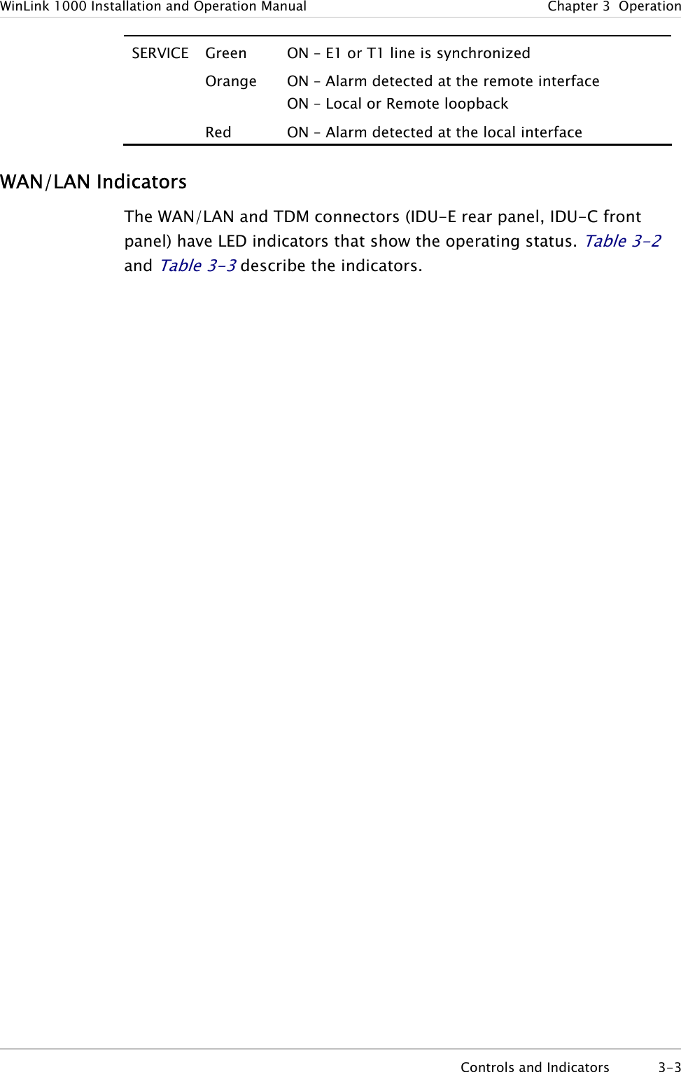
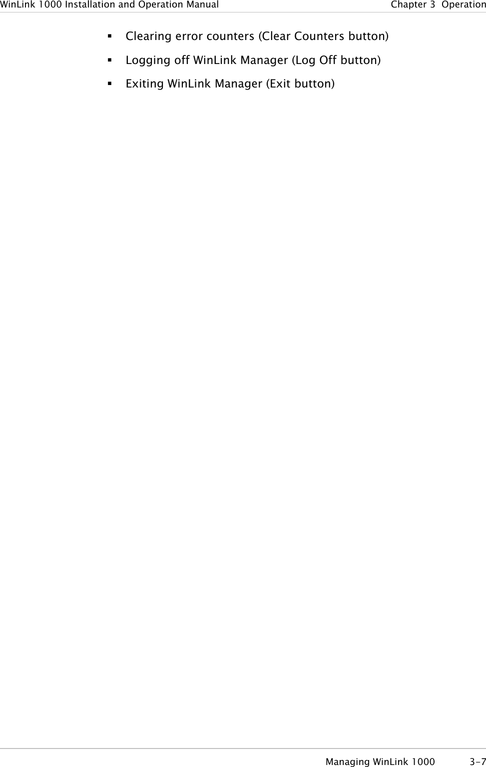
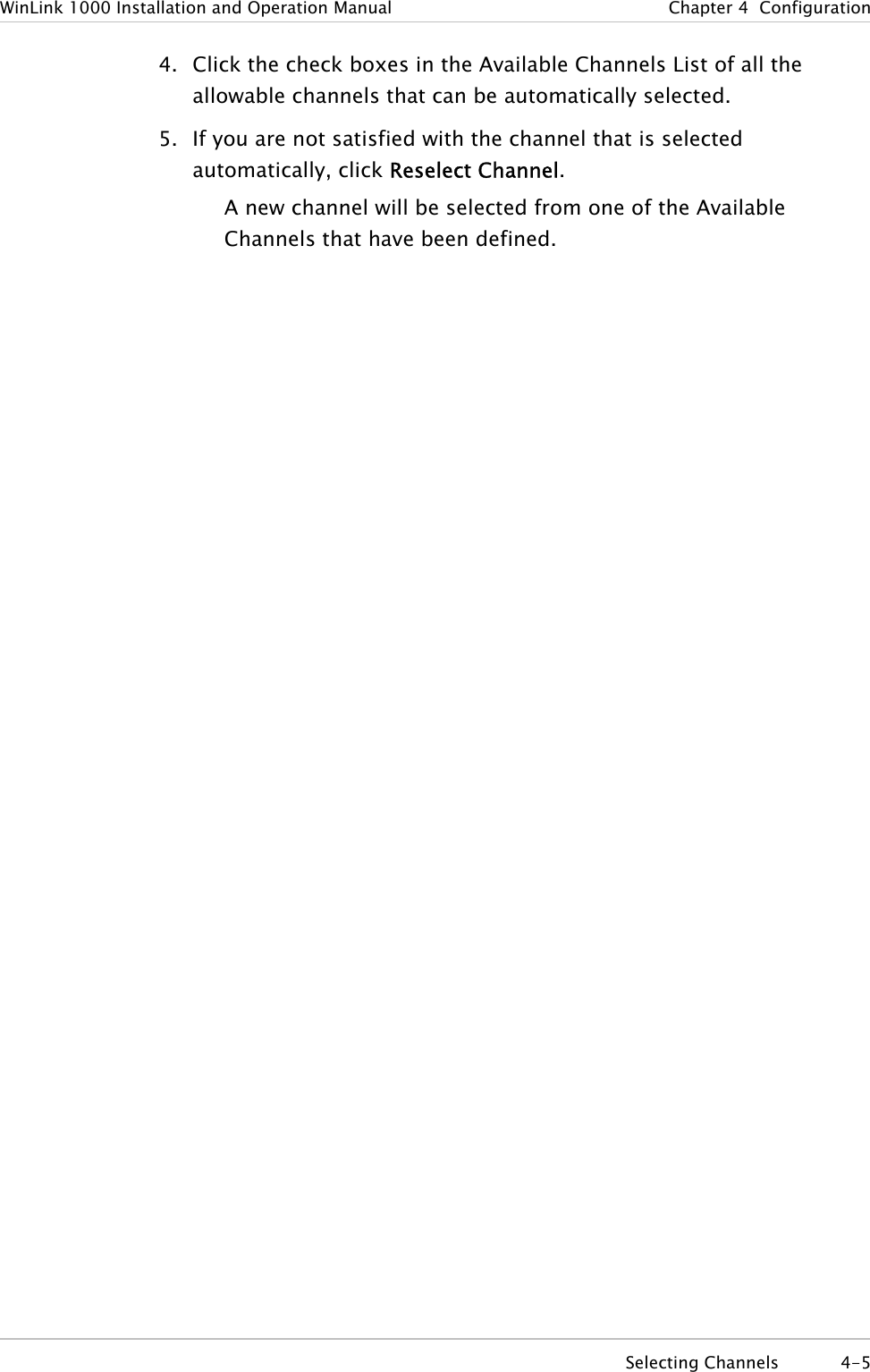
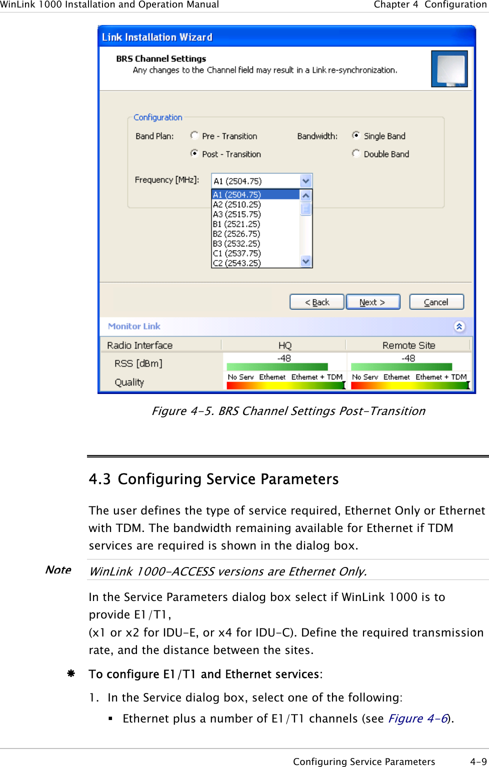
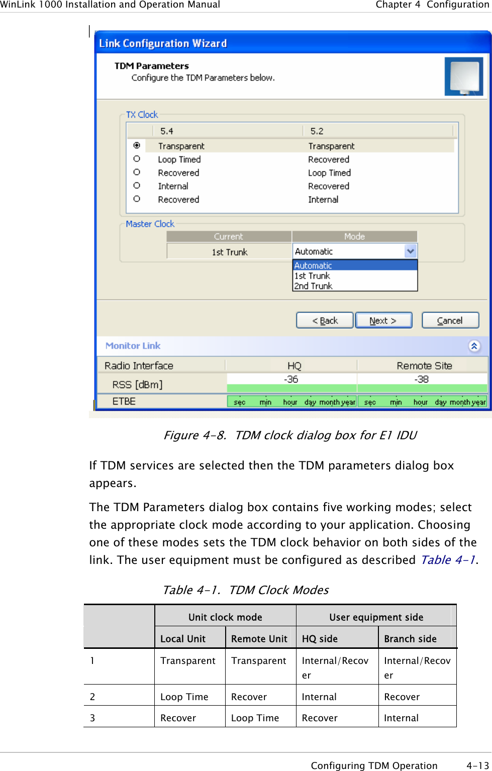
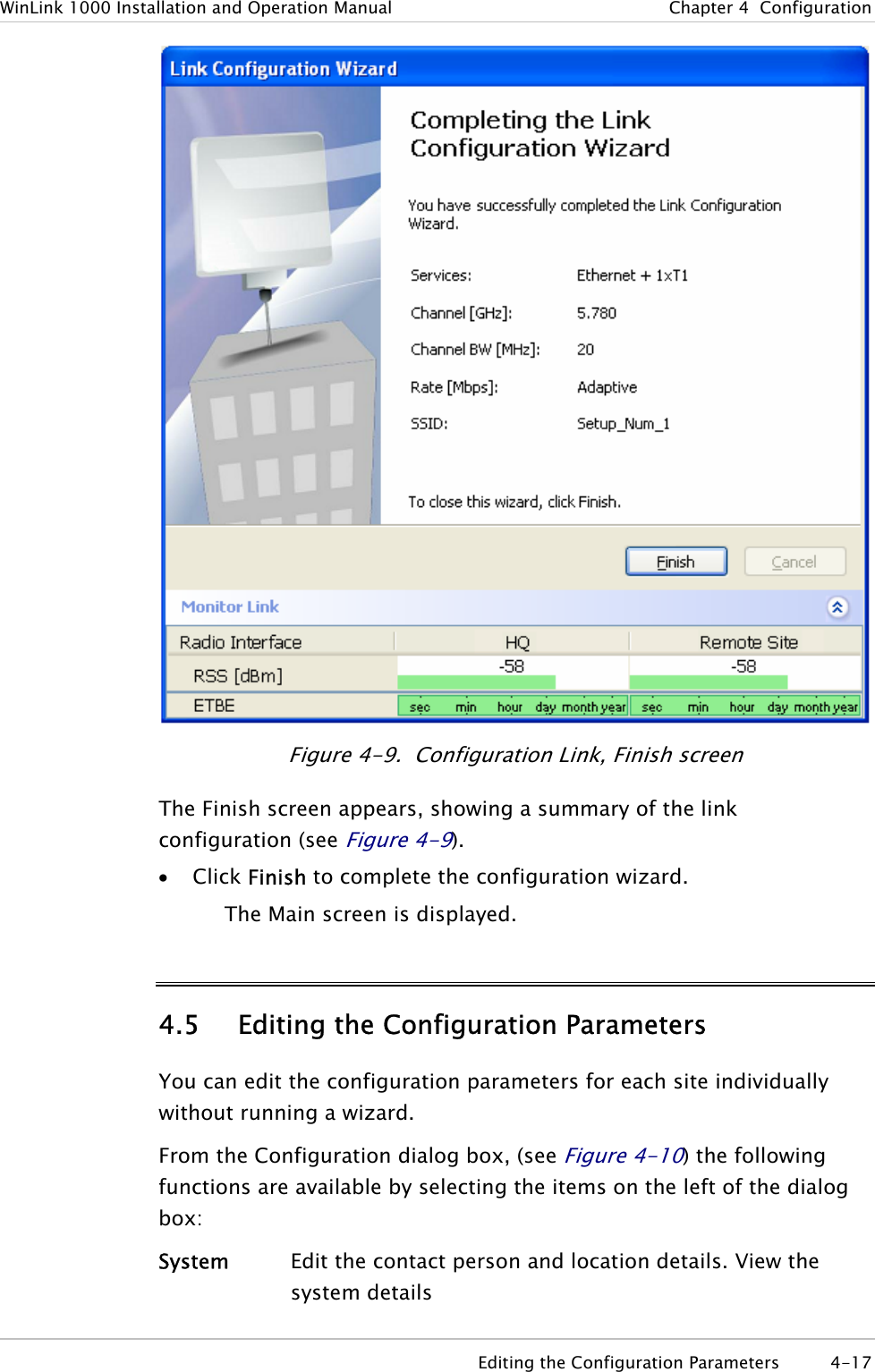
![Quick Start Guide Installation and Operation Manual Beeper Sequence =beeper on =beeper off Description [approx. 1s] Best Signal so far Signal quality increased No change in signal Signal quality decreased [approx. 2s] No air link Note Three beeps and a pause is the best signal Two beeps and a pause, signal quality increased One beep and pause is no signal change Any other signal detects no signal between ODUs. 8. Secure the site B ODU to the mast/wall. 9. At site A, adjust the ODU slowly while listening to the beeper sequence until the best signal is attained. 10. Secure the site A ODU to the mast/wall. 11. Monitor the link quality for about 15 minutes to verify stability. 12. Connect the management station to one of the two IDUs in the link. 13. Double-click the WinLink 1000 Manager icon to start the application. 14. Click the Installation button to open the installation wizard and follow the installation steps. After selection of the radio channel and the link rate (as determined in the Link Budget Calculator utility), verify that the link quality bar in the WinLink 1000 manager is within the green range for TDM service and within the yellow range for Ethernet service. 6 Installing the WinLink 1000 Units WinLink 1000](https://usermanual.wiki/Radwin/AMWL1240H.Users-Manual-Part-1/User-Guide-800483-Page-10.png)
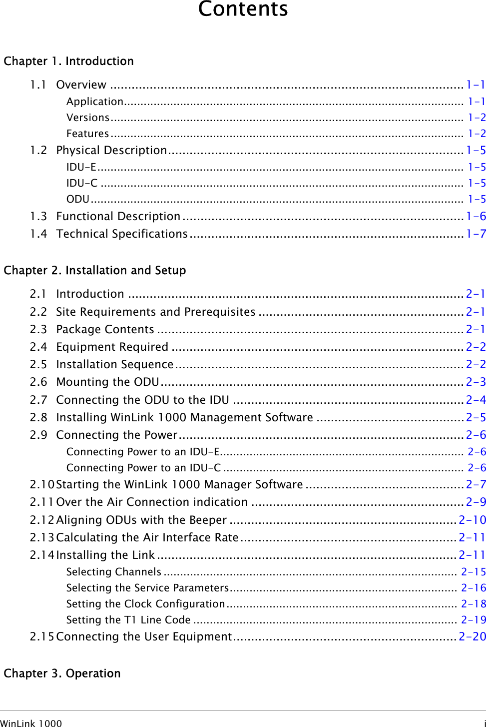
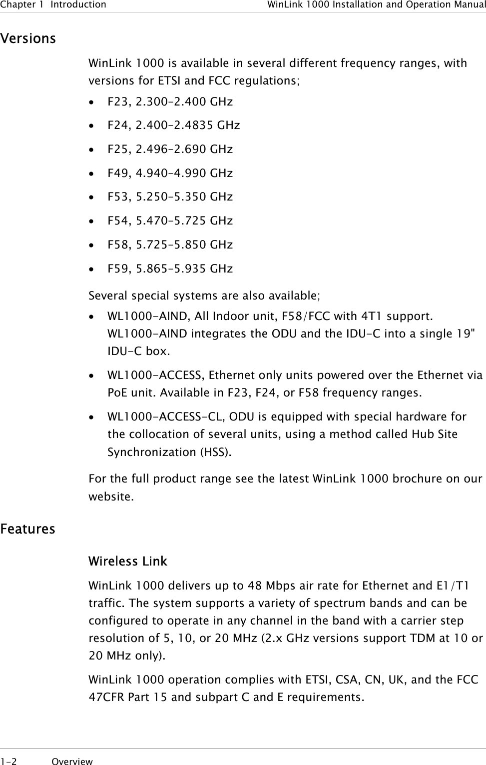
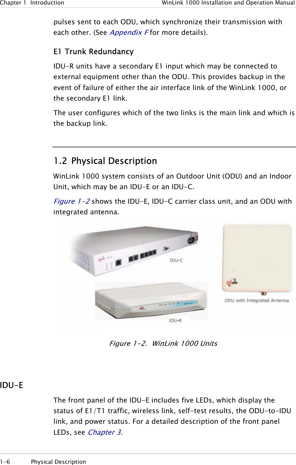
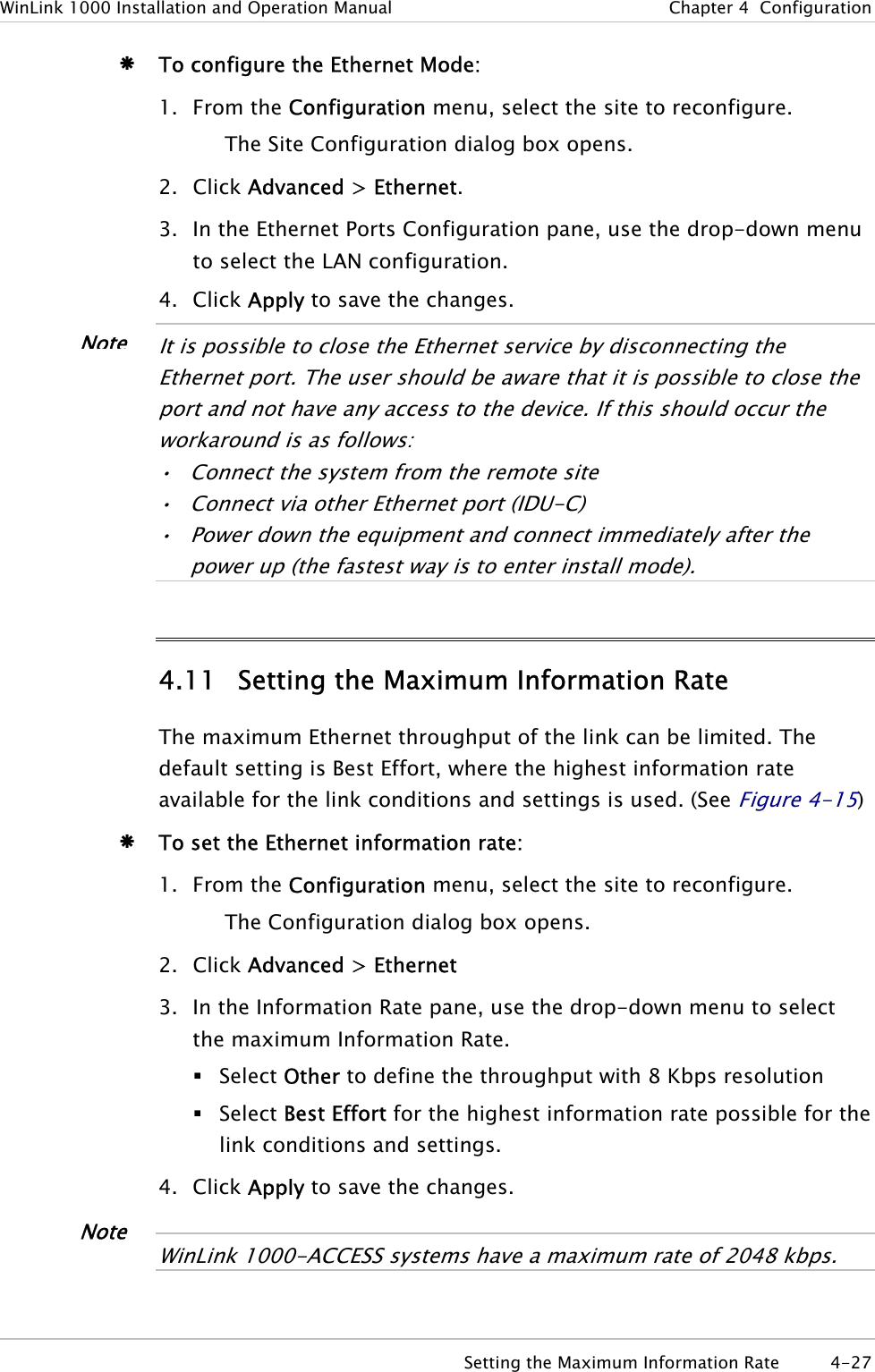
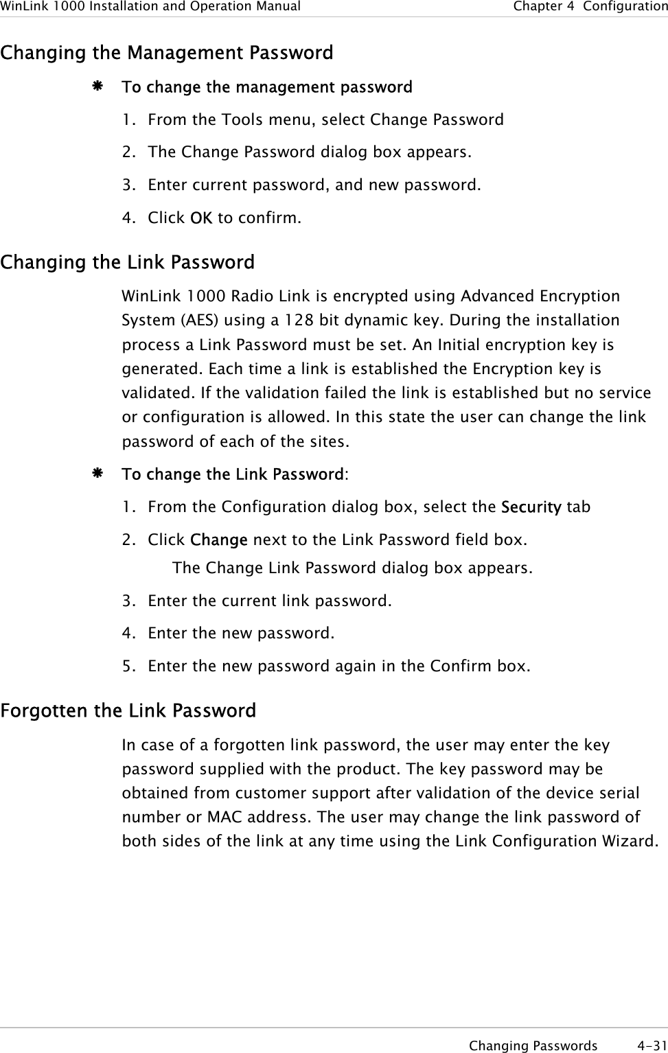
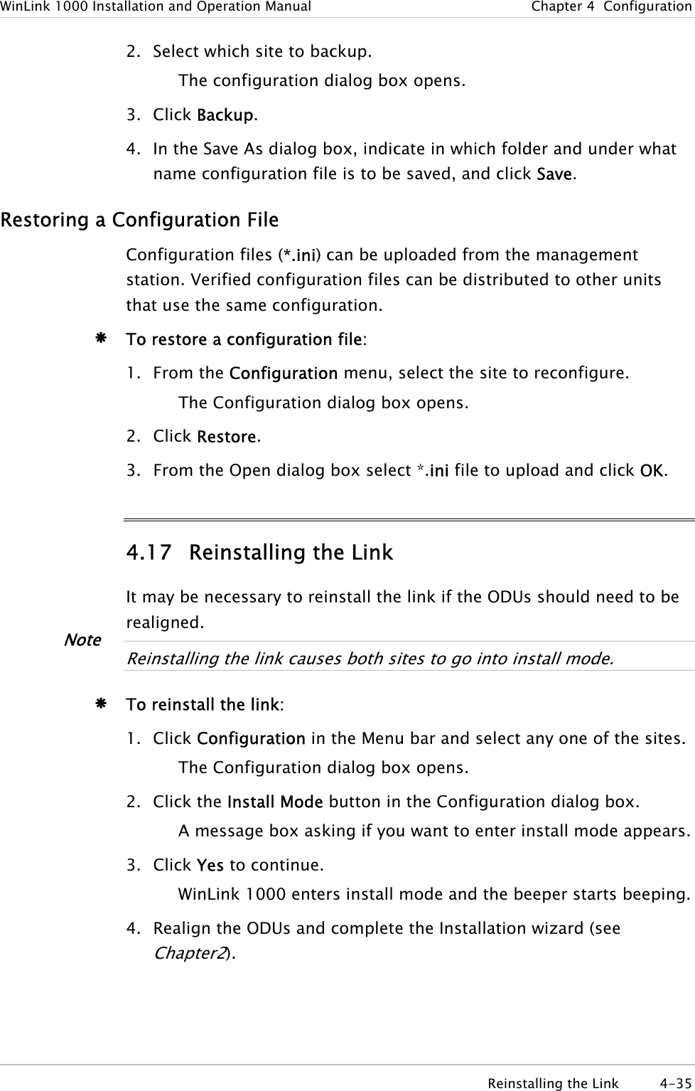
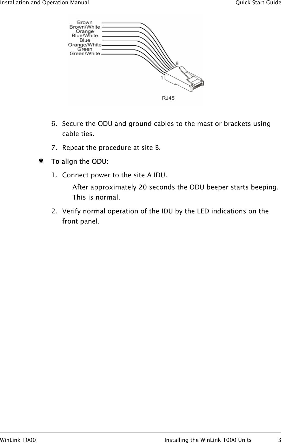
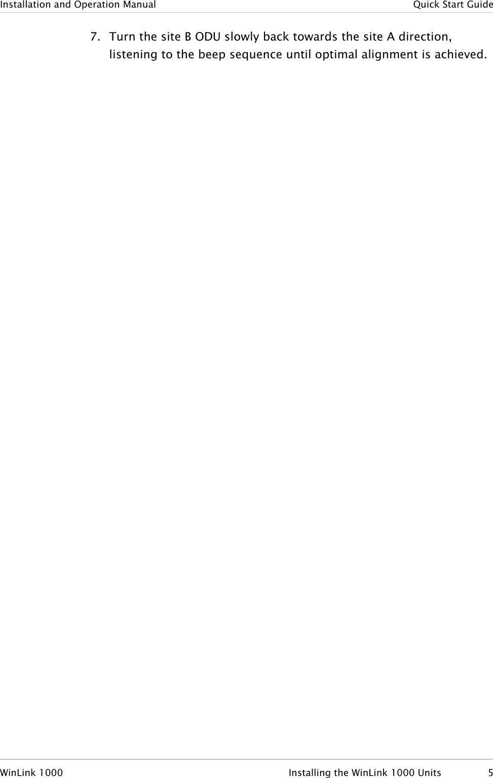
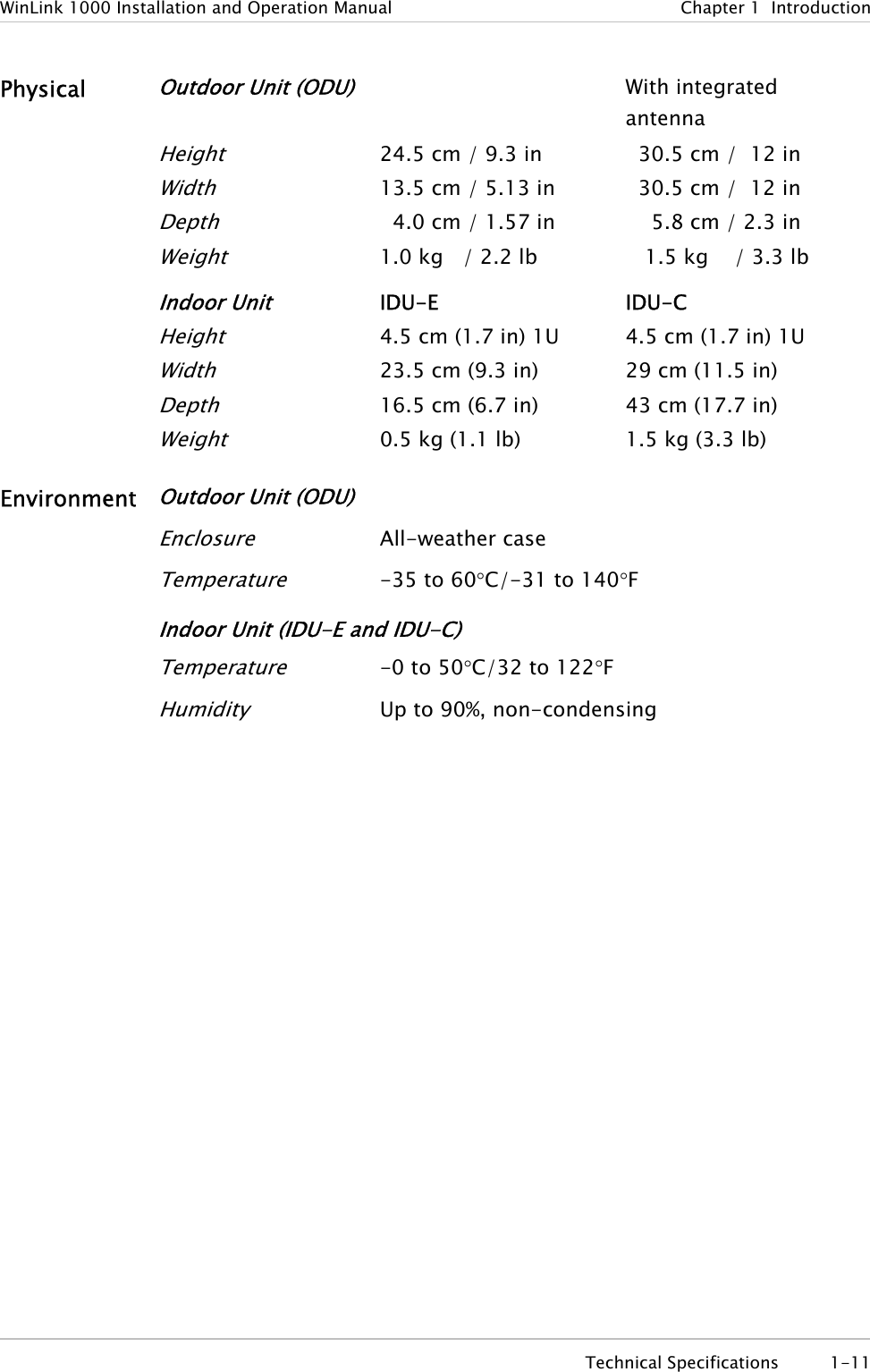
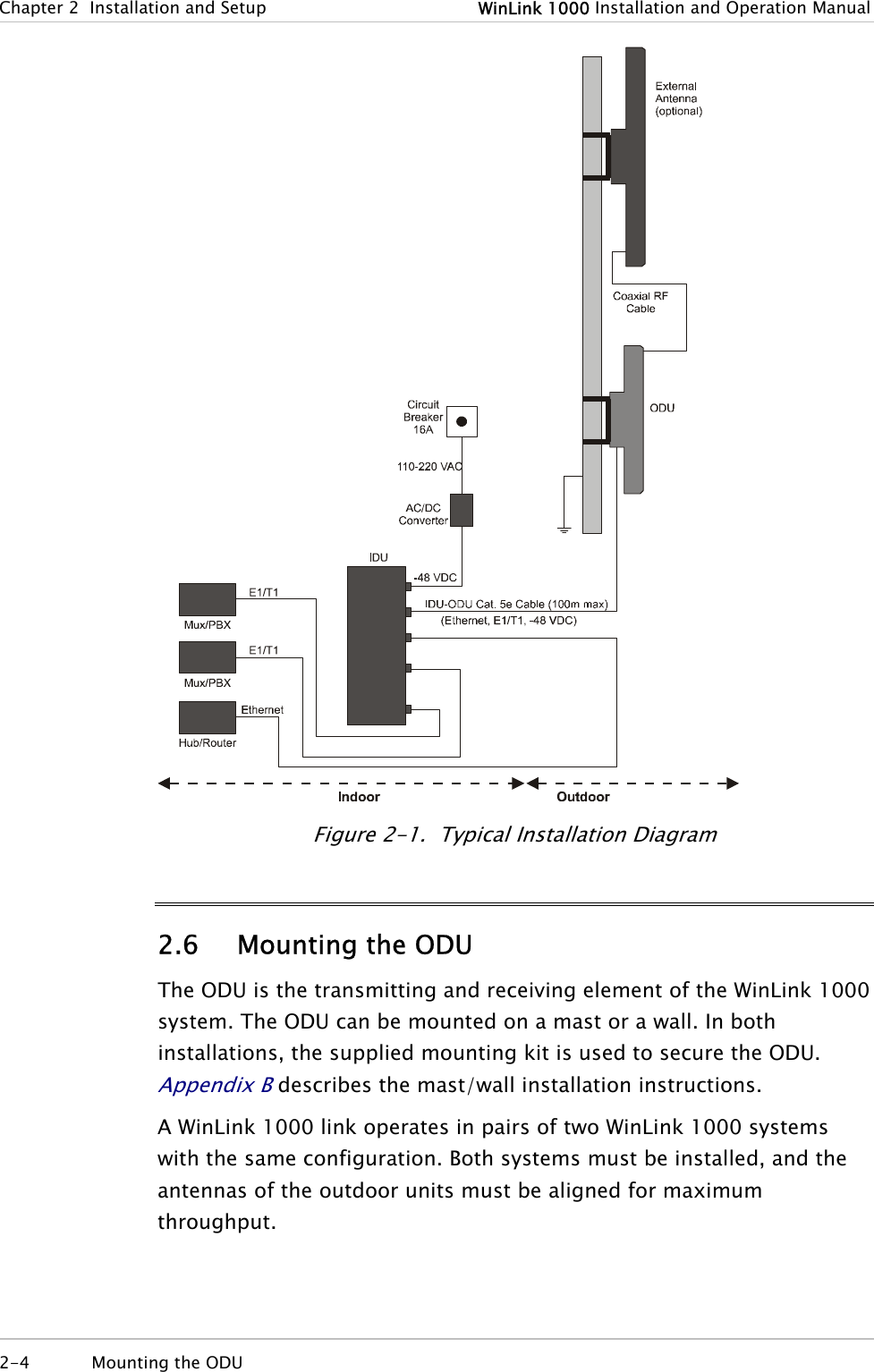
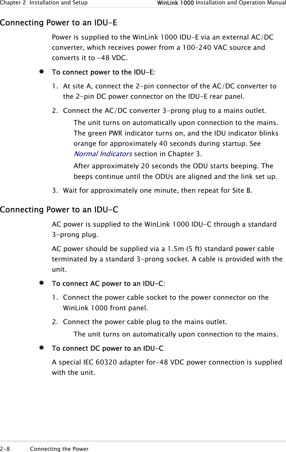
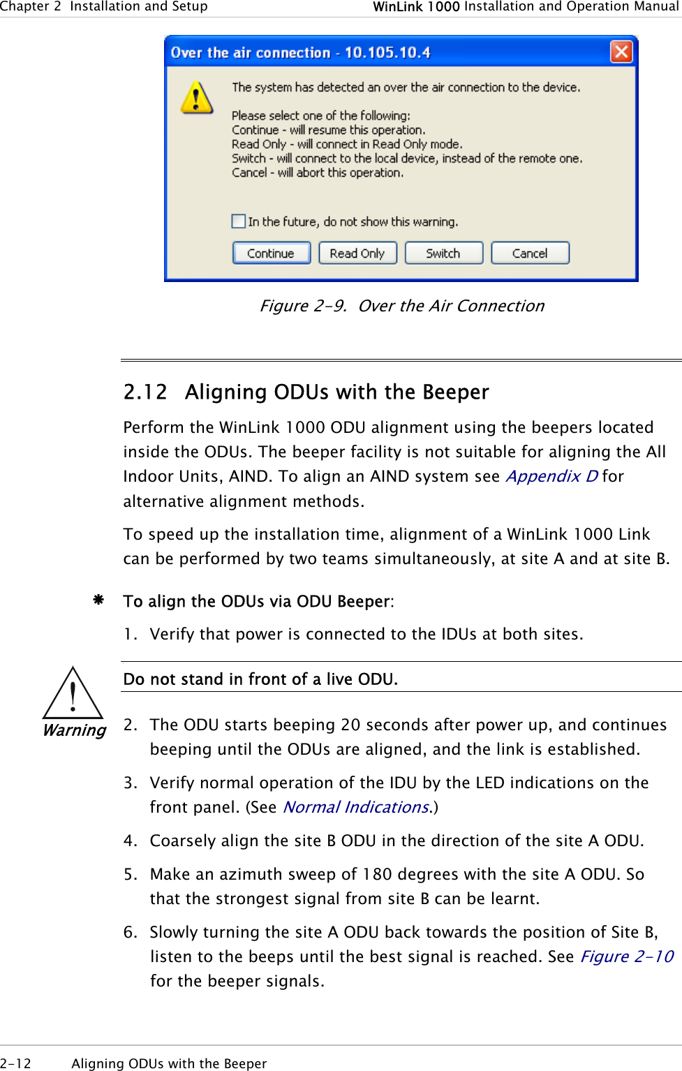
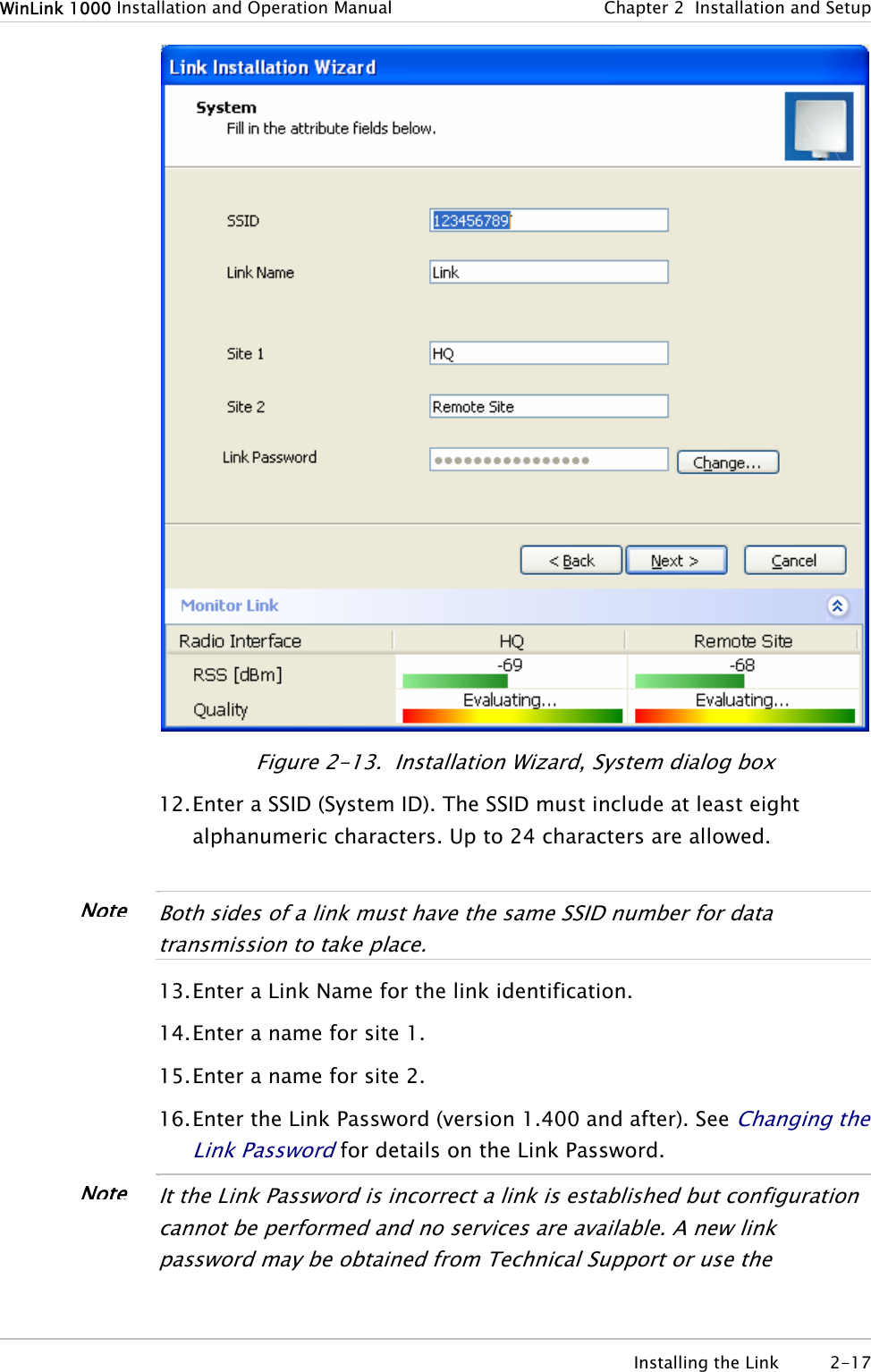
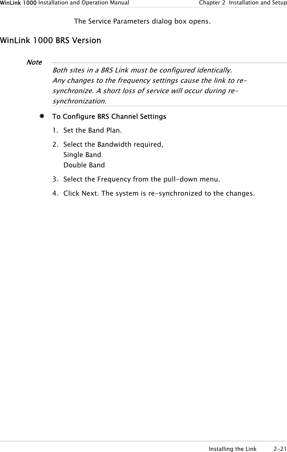
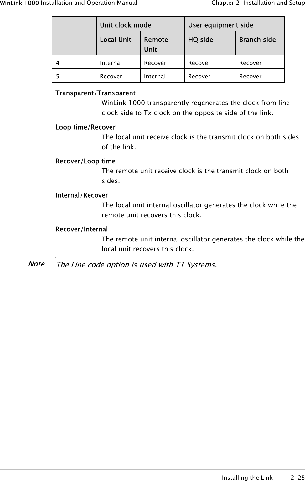
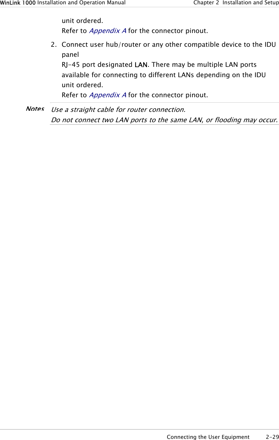
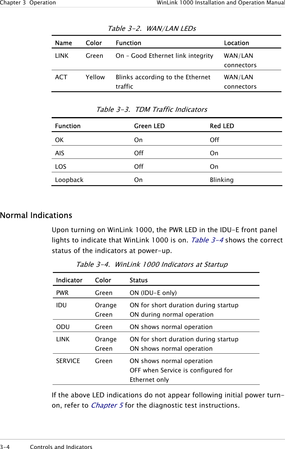
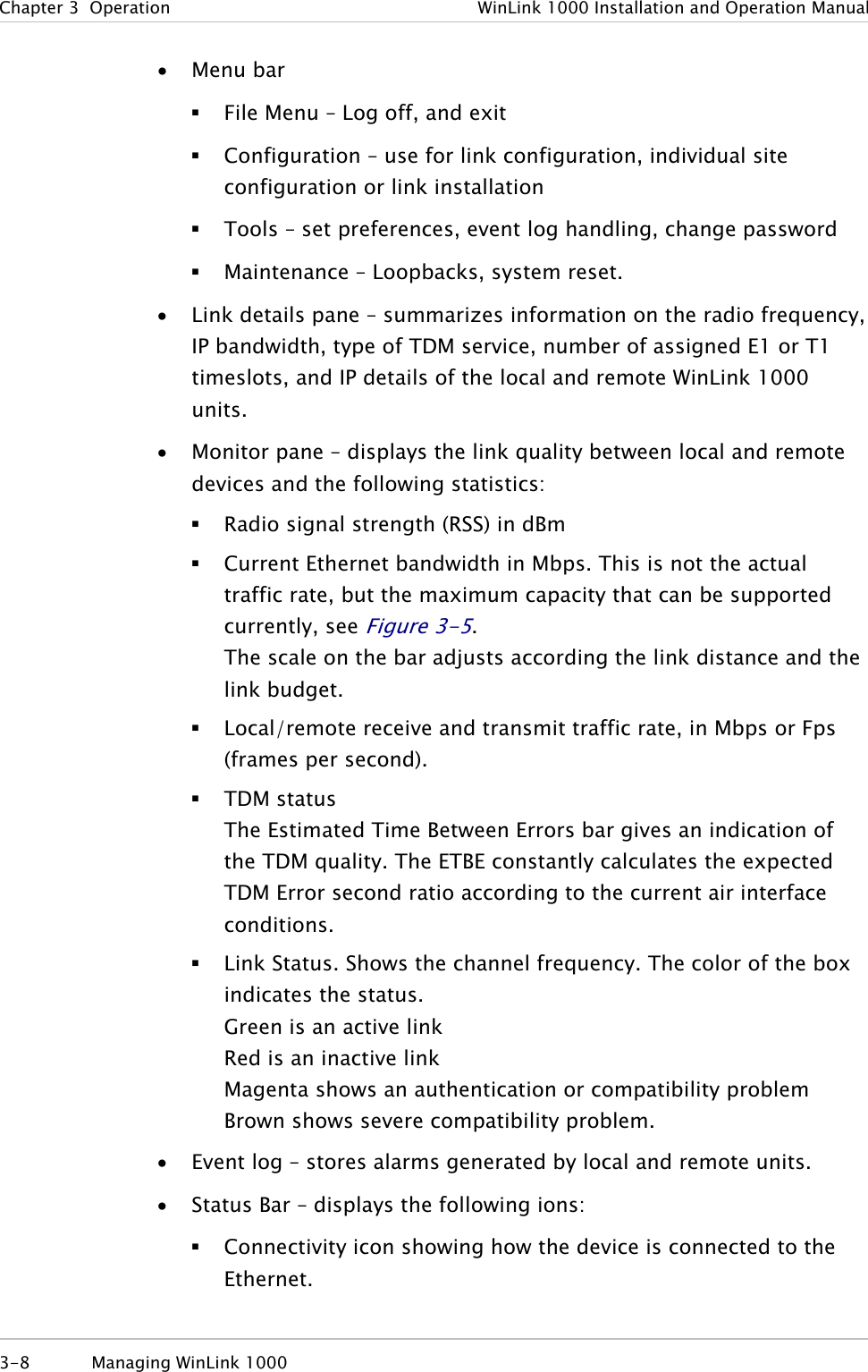
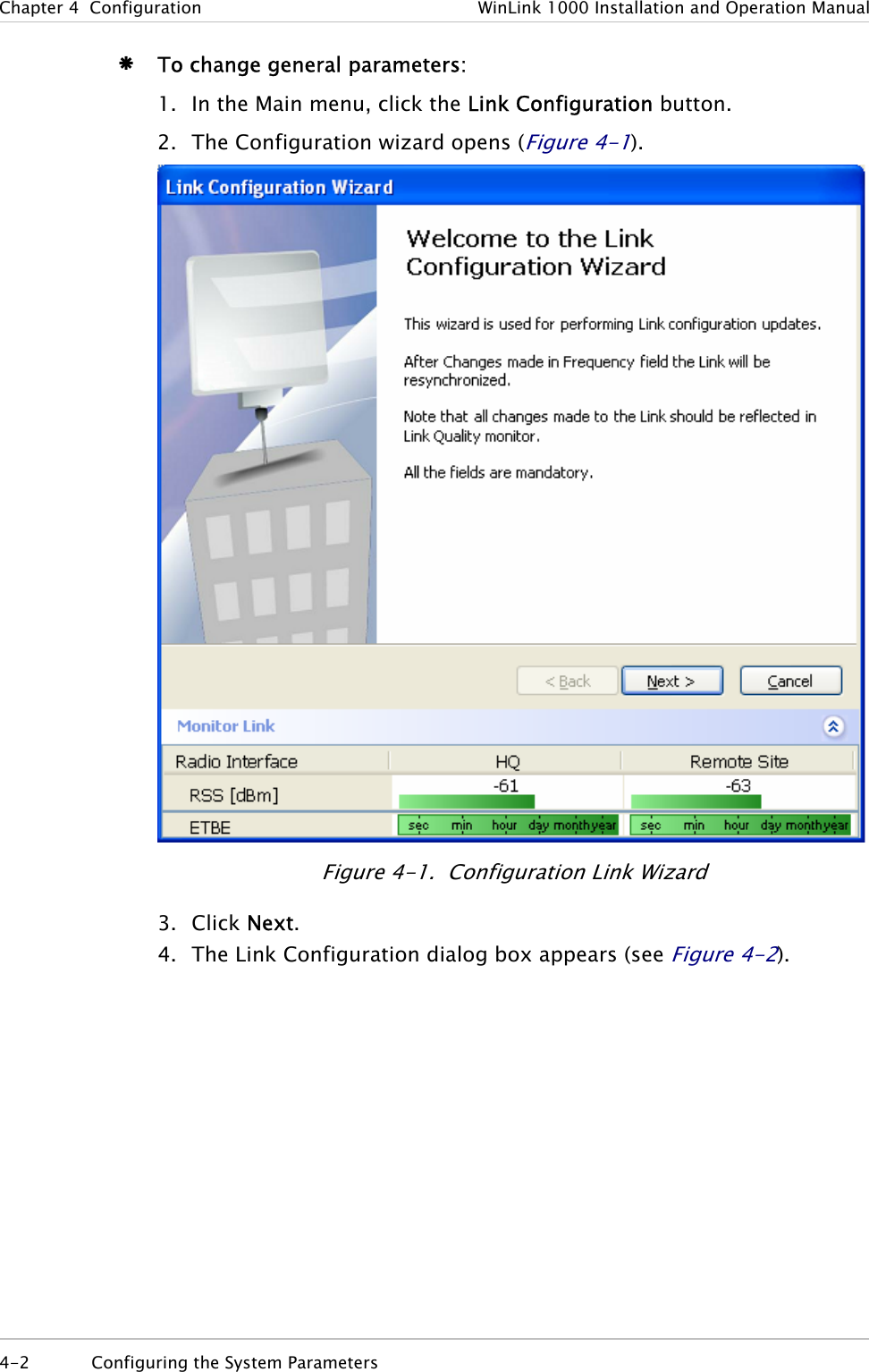
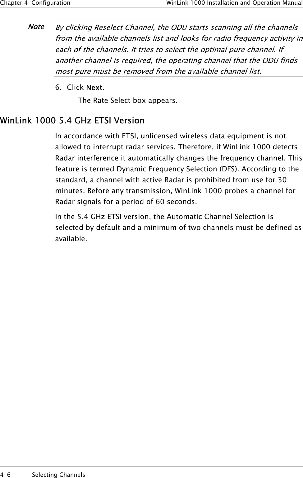
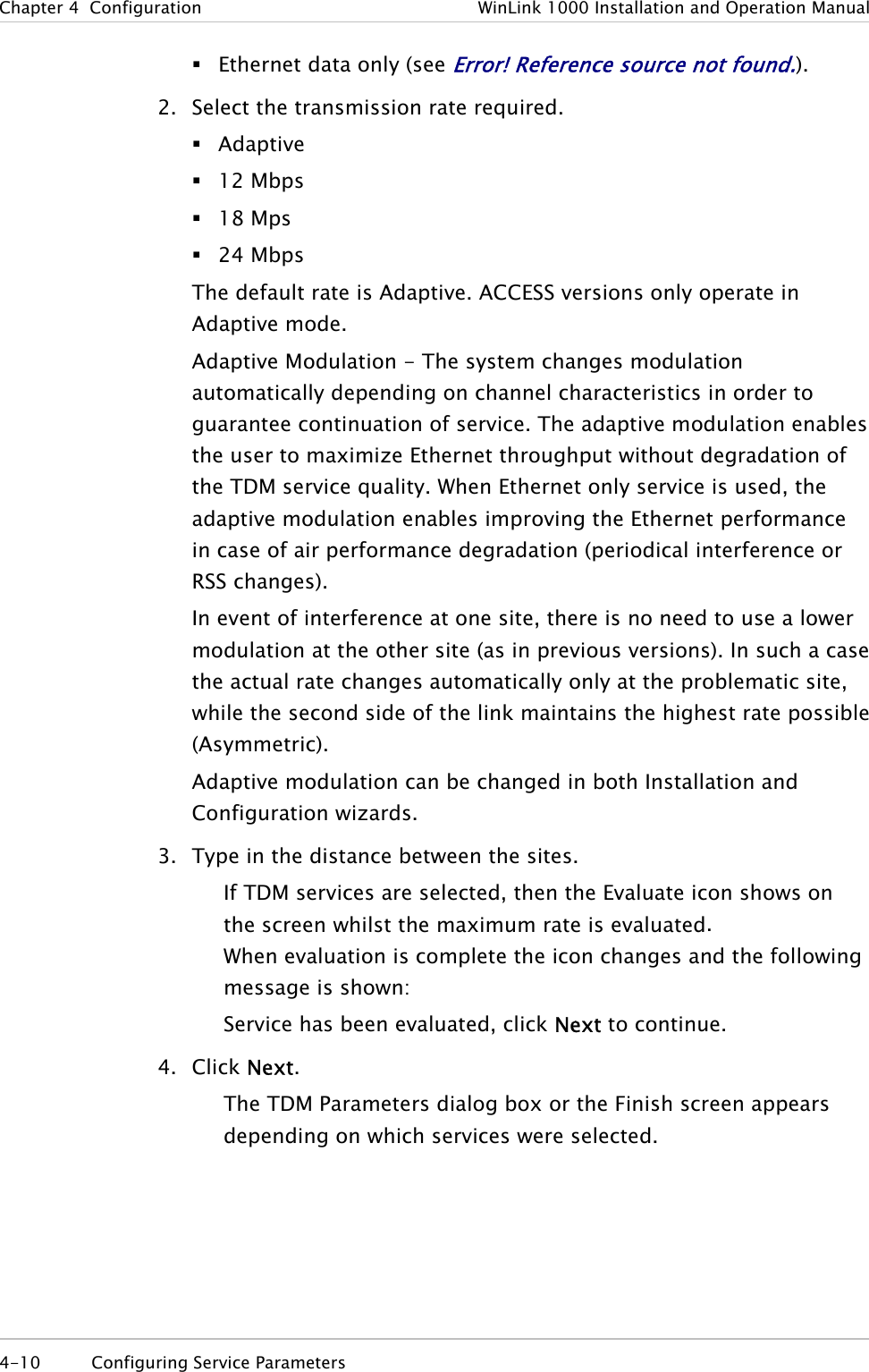
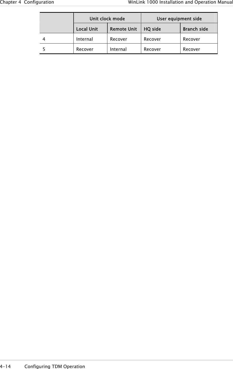
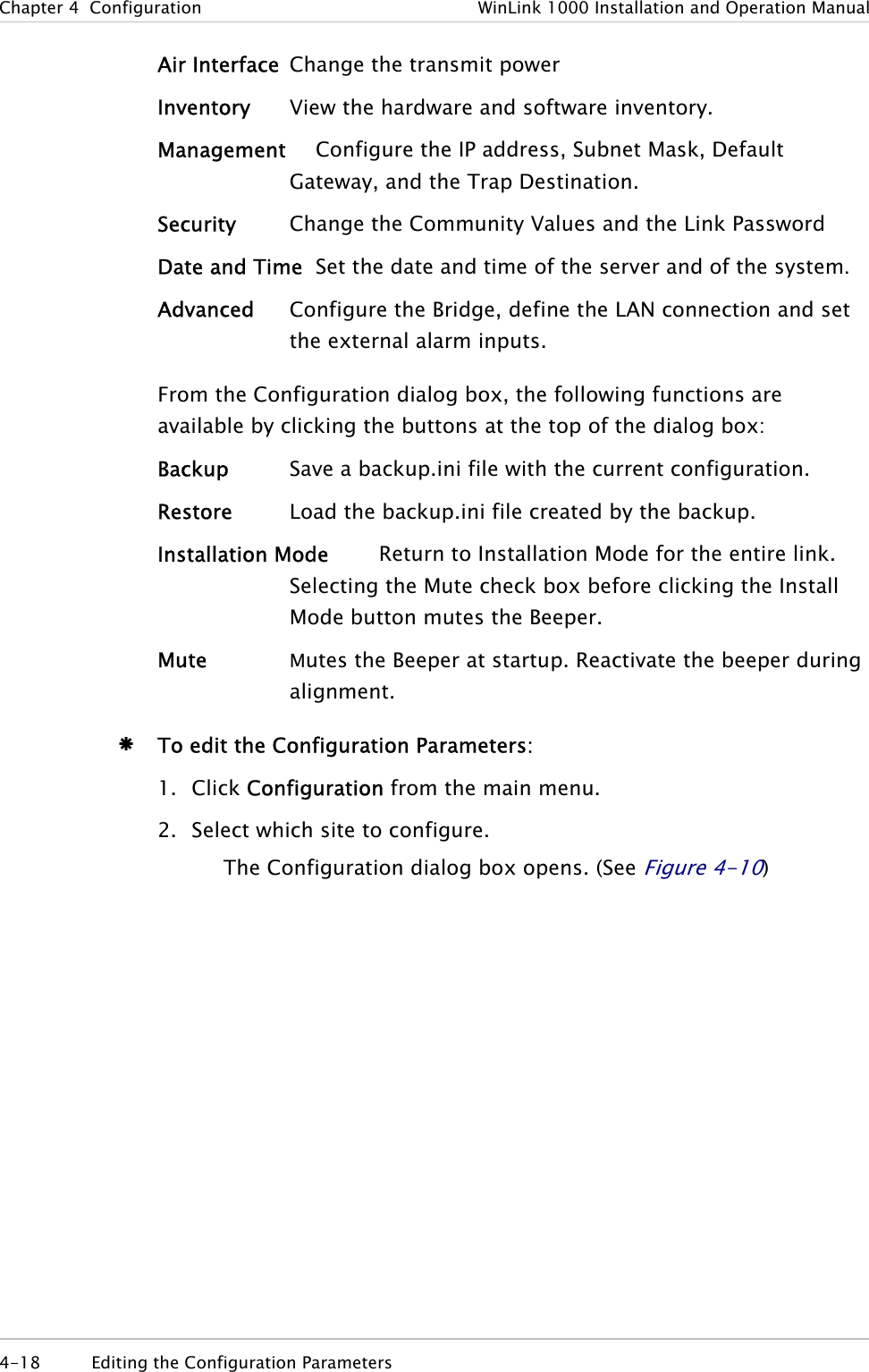
![WinLink 1000 Installation and Operation Manual Chapter 1 Introduction 1.4 Technical Specifications Air Interface Technology OFDM Duplexing Method Time Division Duplex (TDD) Capacity Configurable up to 48 Mbps Modulation OFDM - BPSK, QPSK, 16QAM, 64QAM Channel Resolution 5/10/20 MHz (BRS systems 5 and 10 MHz only) Transmitter Power Specification is different per product, for further details refer to the Link Budget Calculator Range Up to 41 km (25.5 miles) Up to 80 km (50 miles) with an external antenna ACCESS versions up to 20 km. Frequency Bands [GHz] and Standards 2.300–2.483 2.496–2.690 4.940–4.990 5.150–5.350 5.470–5.725 5.725–5.850 FCC, ETSI FCC part 27 (BRS) FCC FCC ETSI FCC Antennas (See Antenna Characteristics in Appendix E) LAN Interface PHY Up to 2 × 10/100BaseT, auto-sensing Framing/Coding IEEE 802.3/U Bridging Self-learning, up to 2048 MAC addresses Line Impedance 100Ω VLAN Support Transparent Frame Size 1536 bytes max Connector RJ-45 E1 Interface Data Rate Unframed (transparent) 2.048 MHz (Specification may be different per ordering Technical Specifications 1-9](https://usermanual.wiki/Radwin/AMWL1240H.Users-Manual-Part-1/User-Guide-800483-Page-25.png)
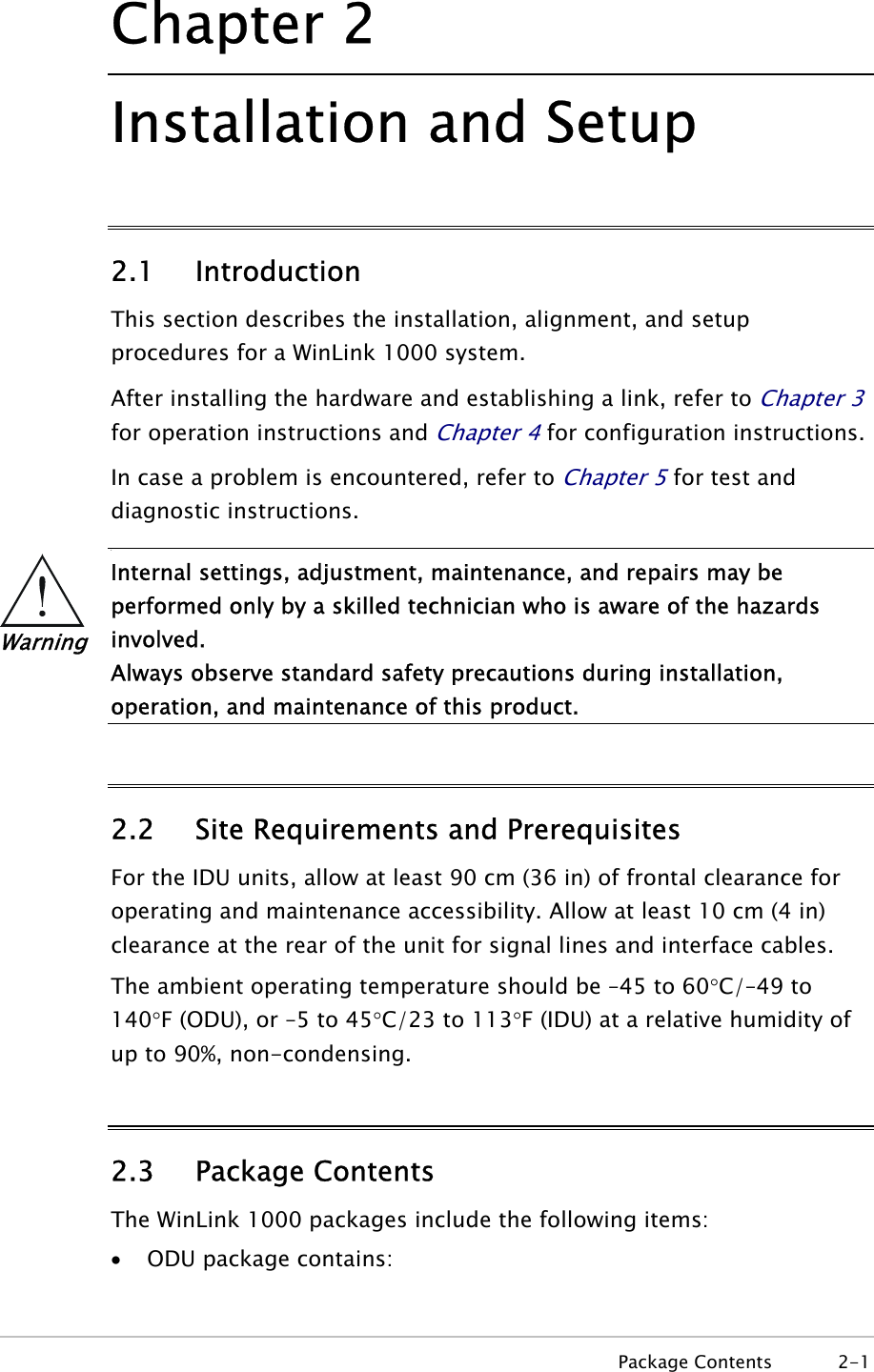
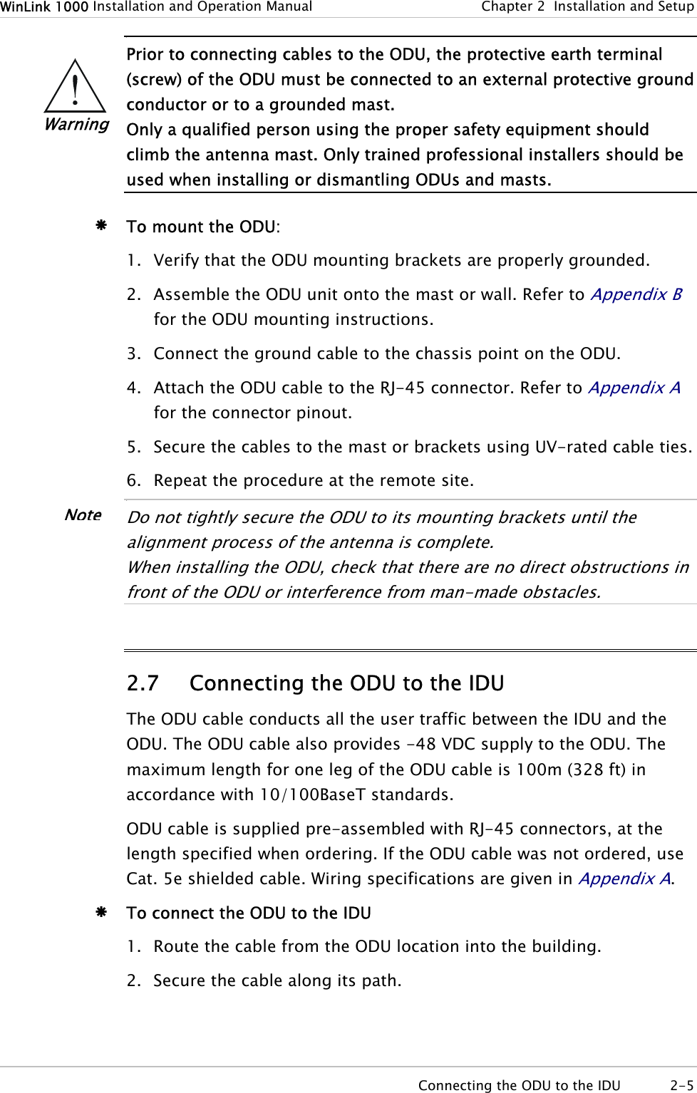
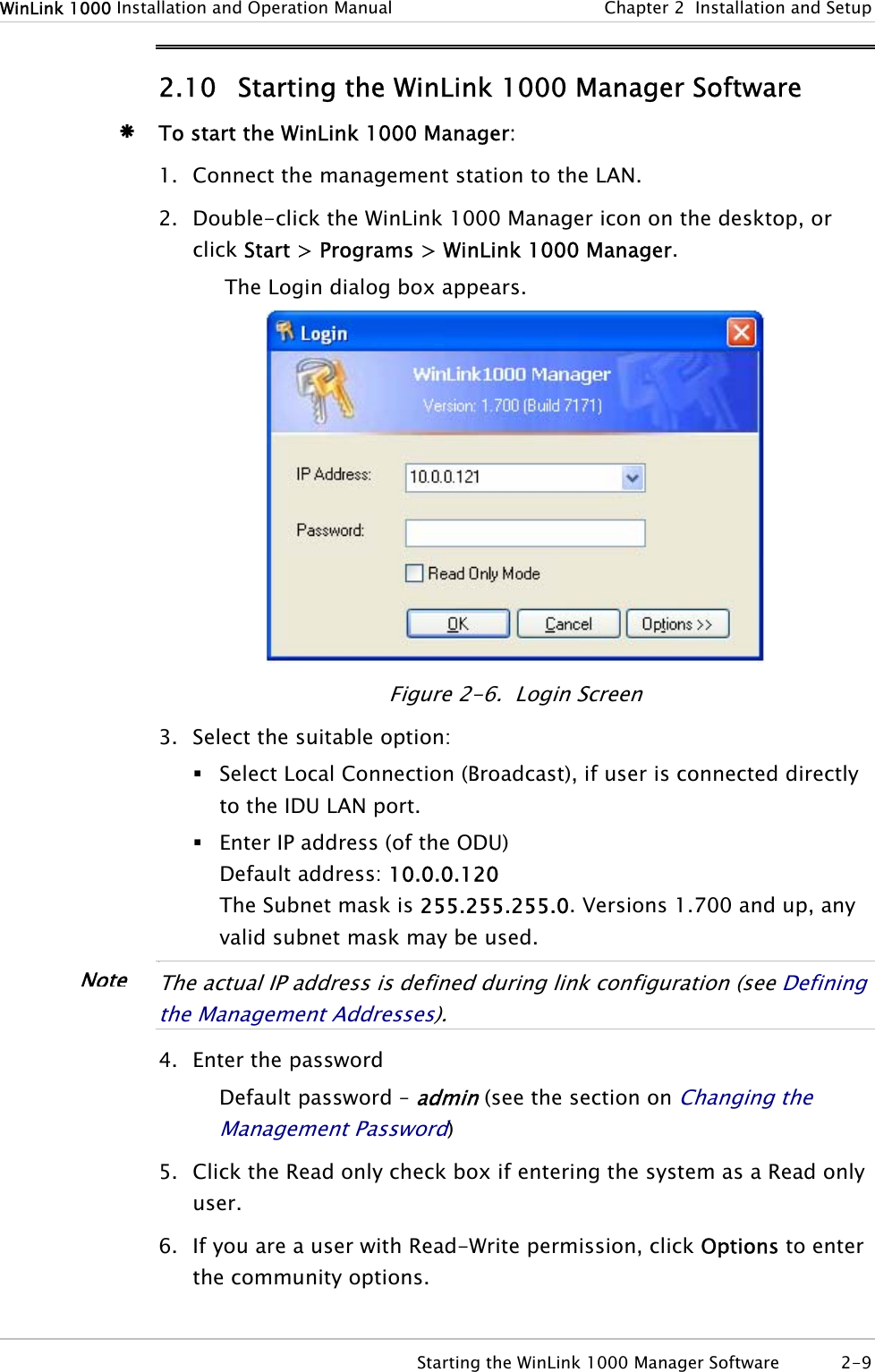
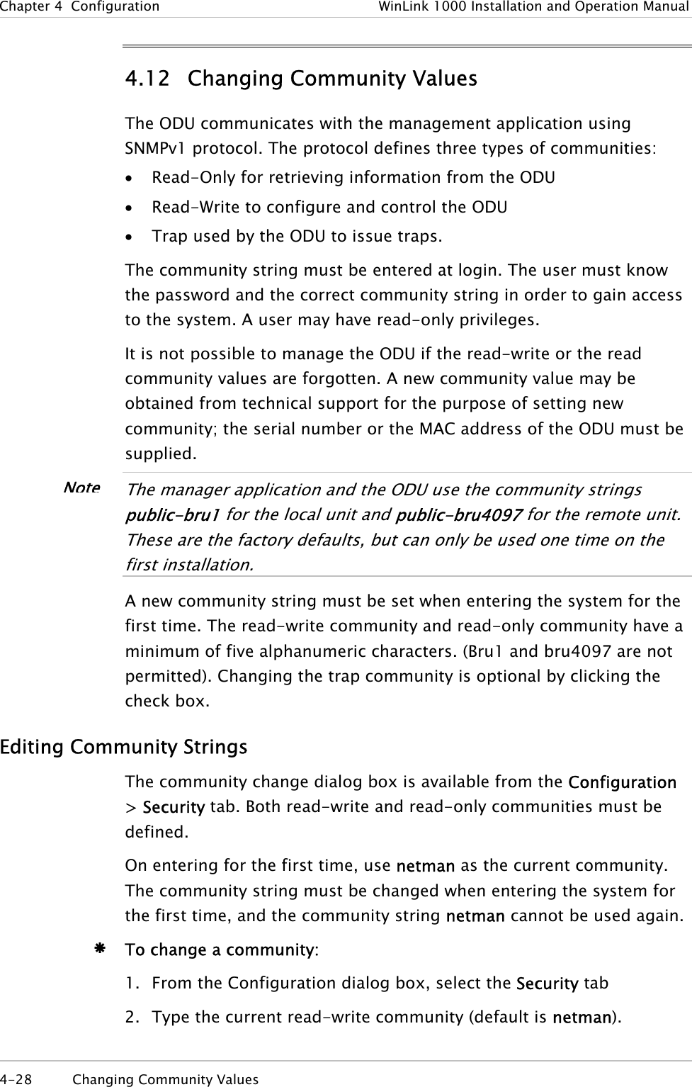
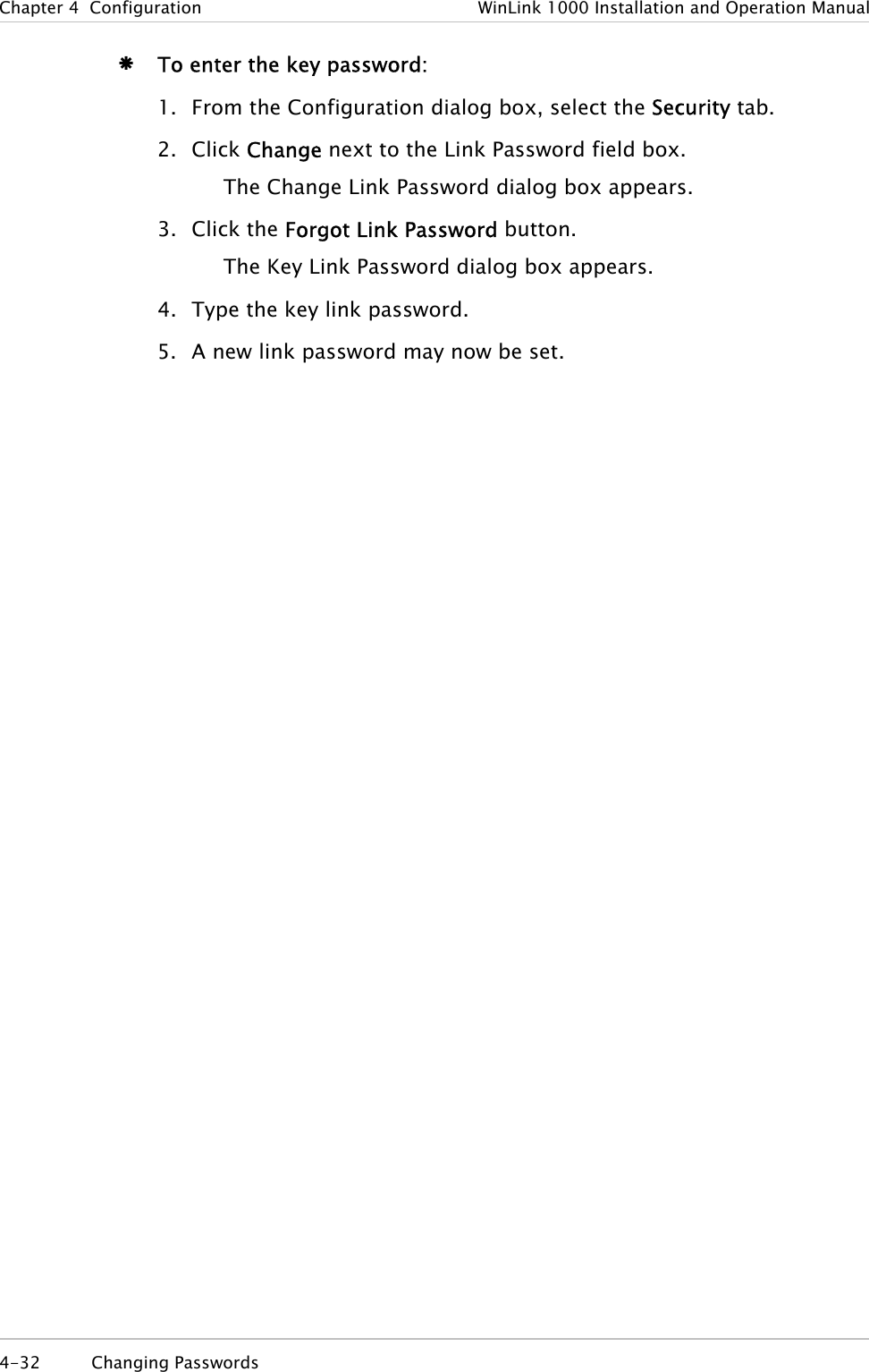
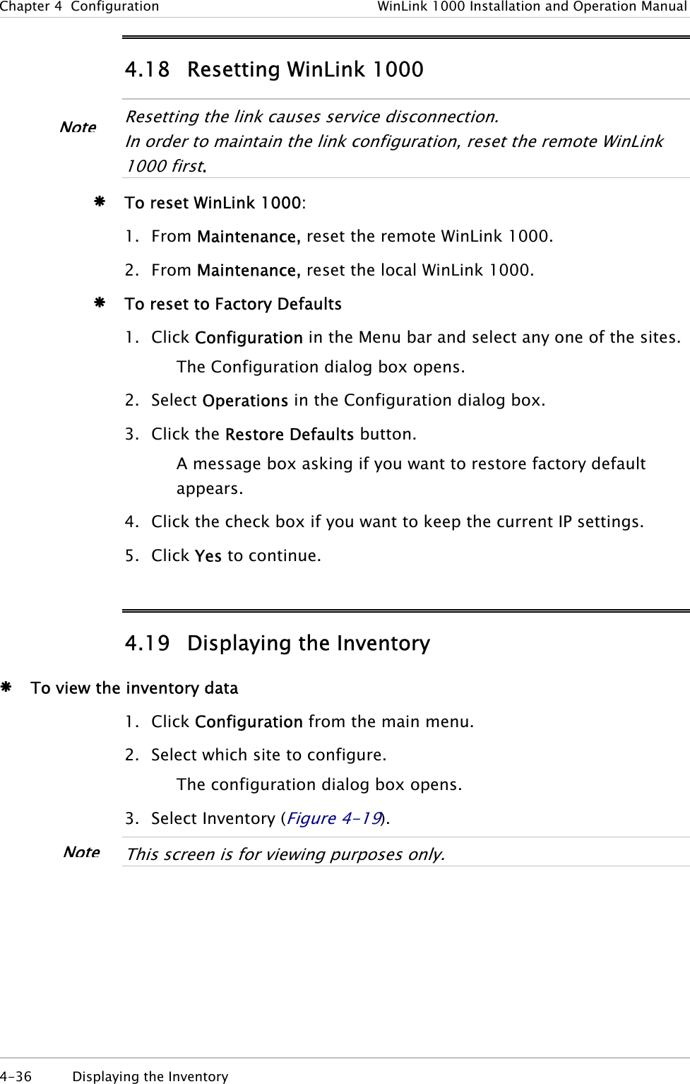
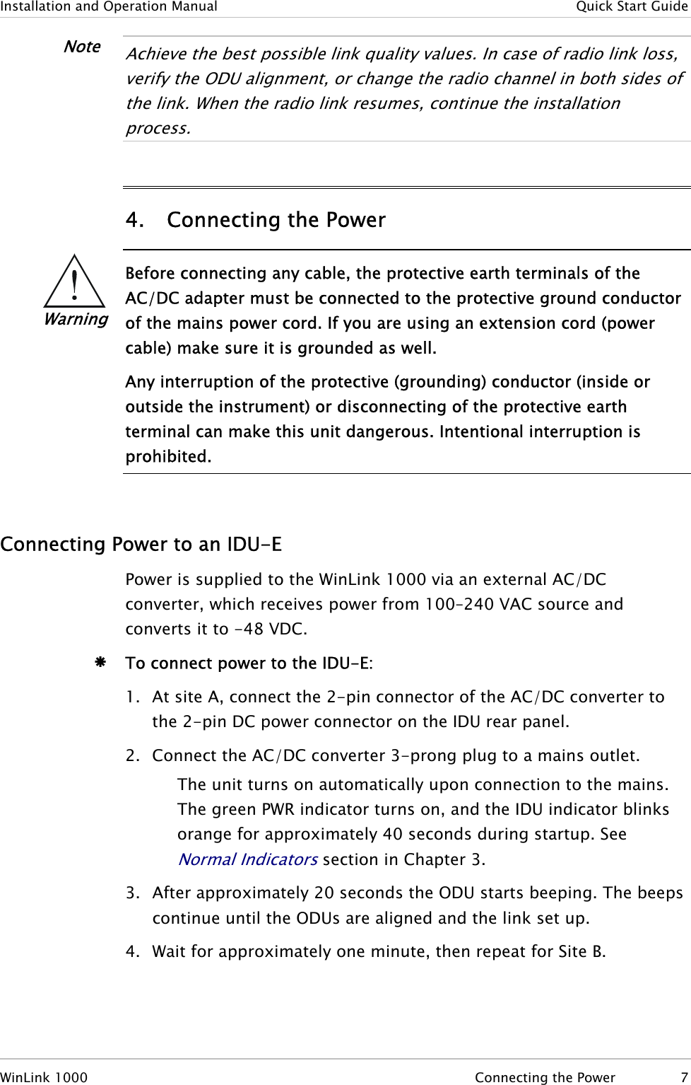
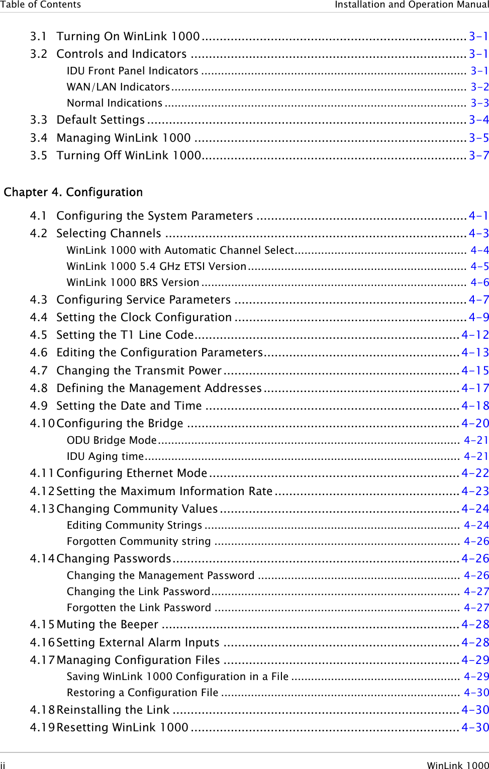
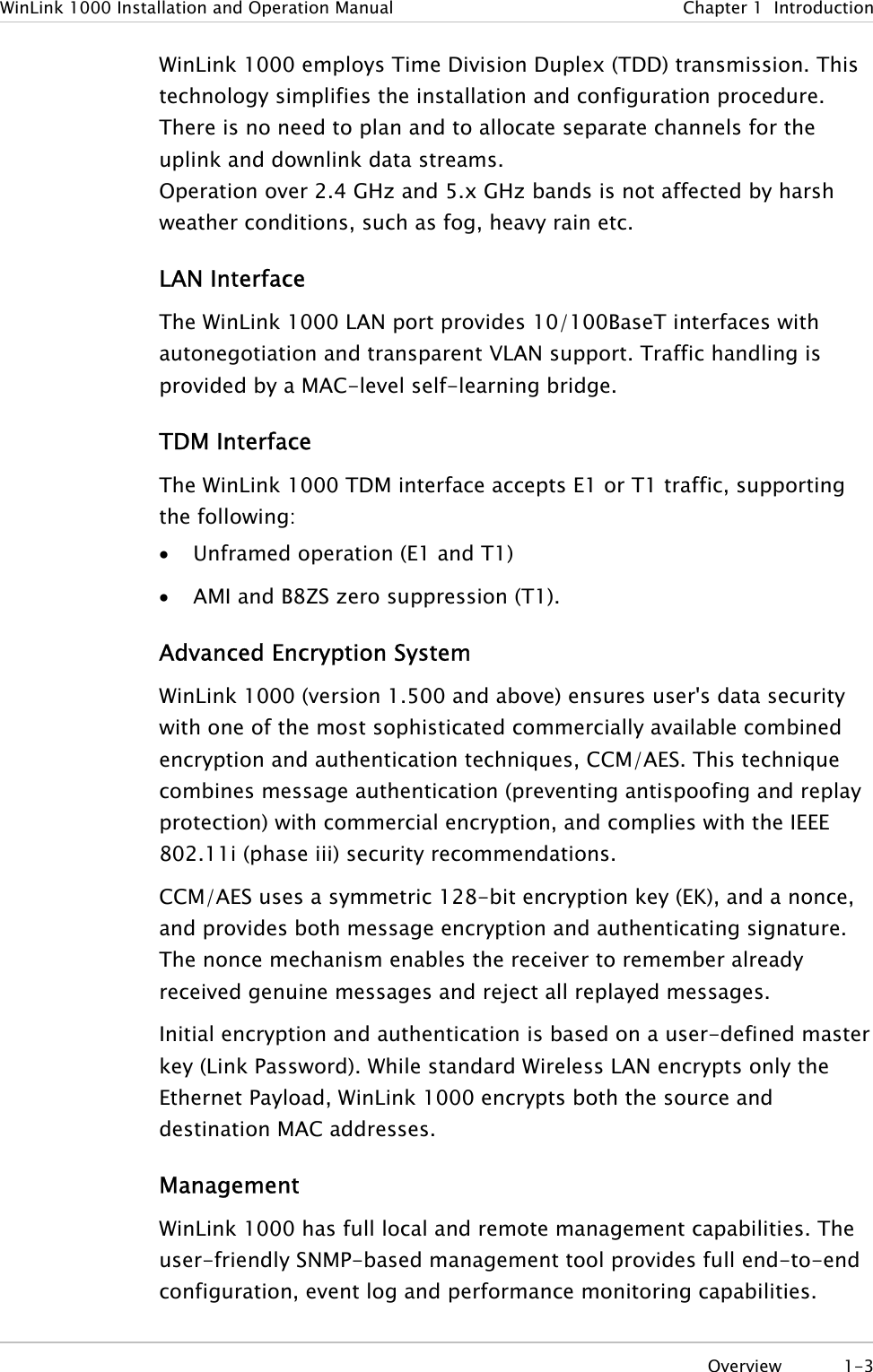
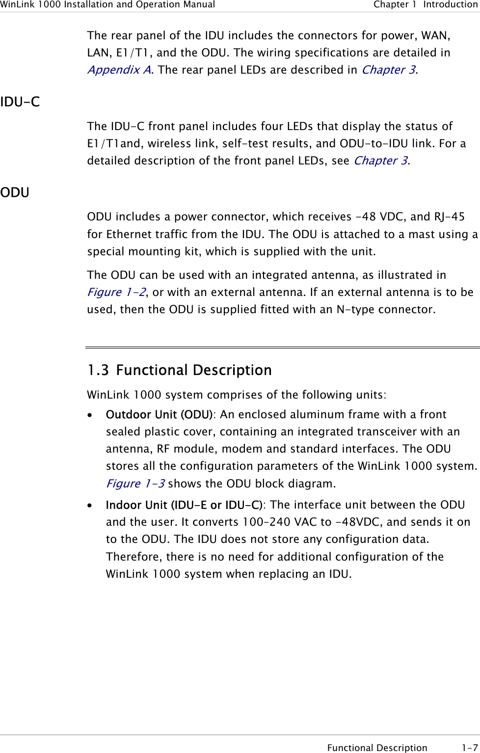
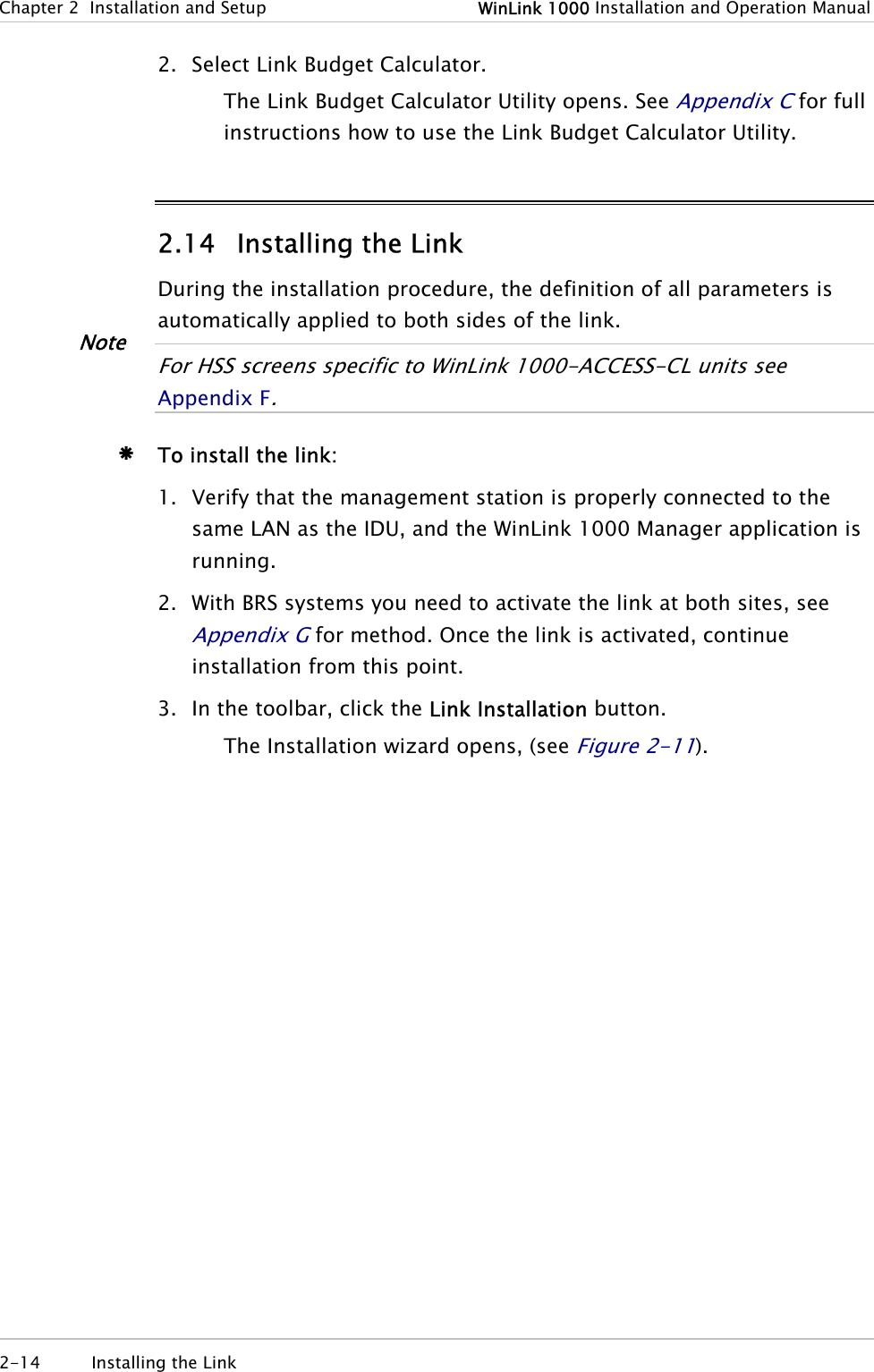
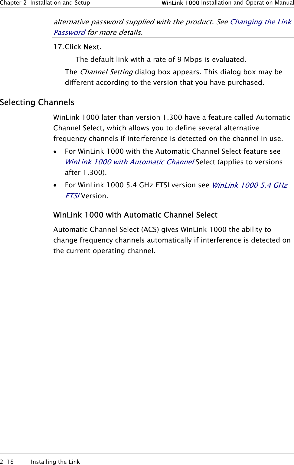
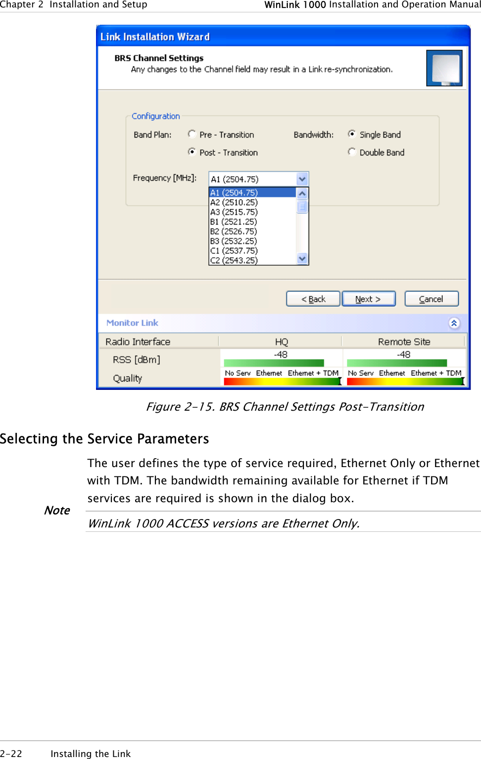
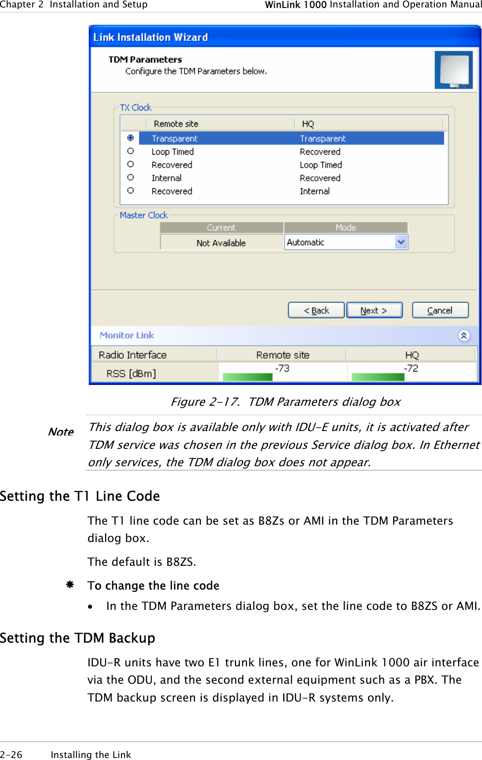
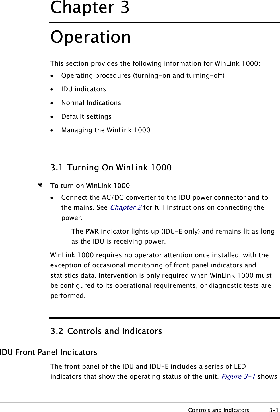
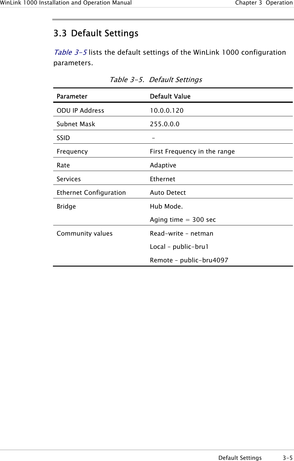
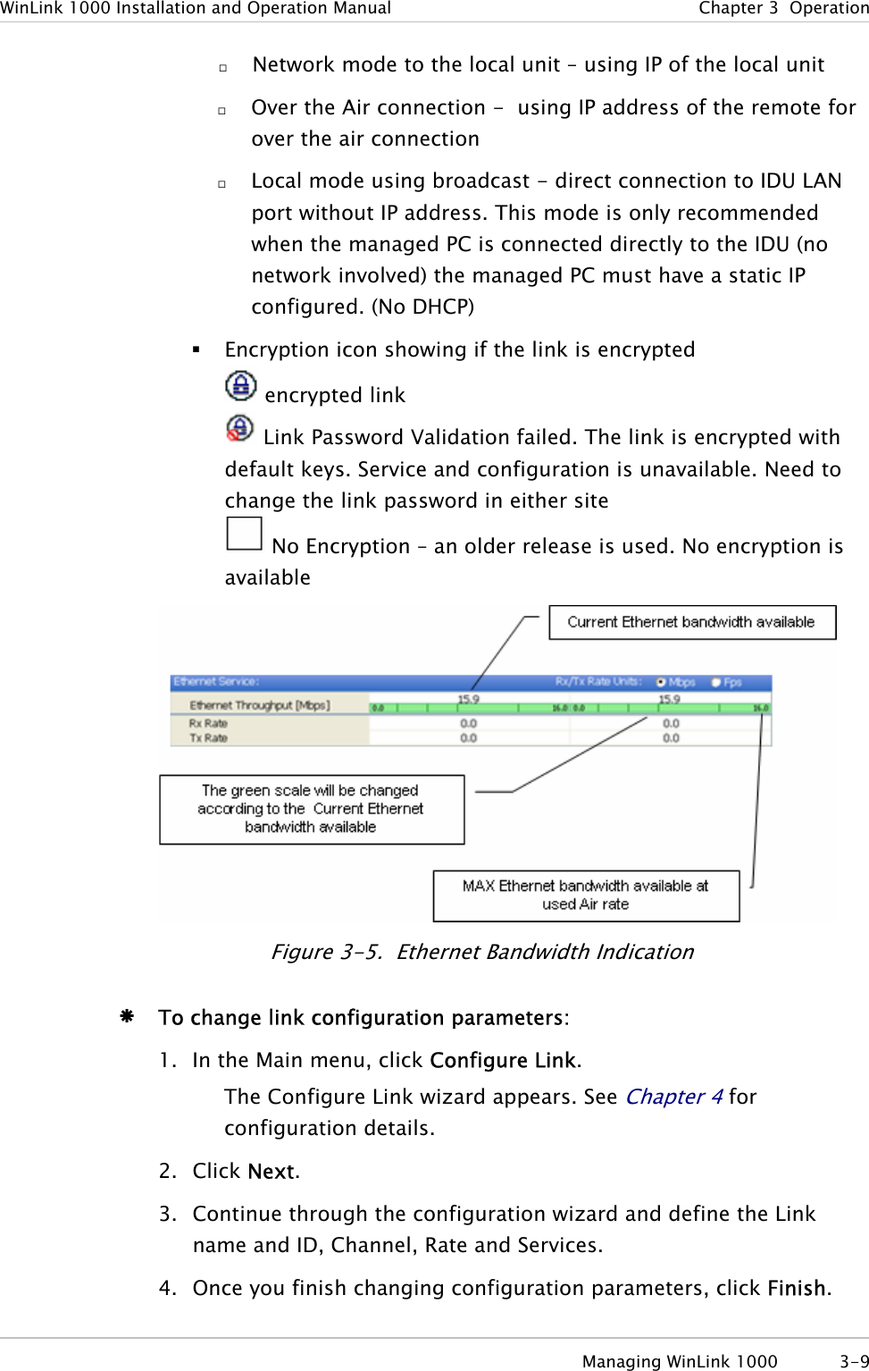
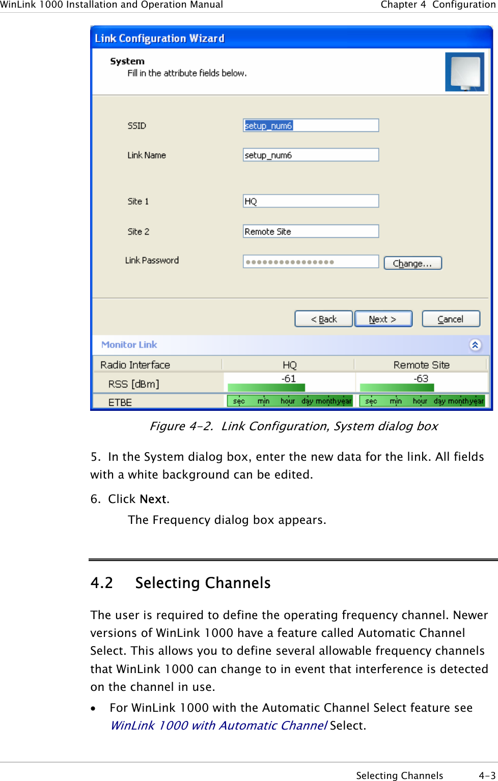
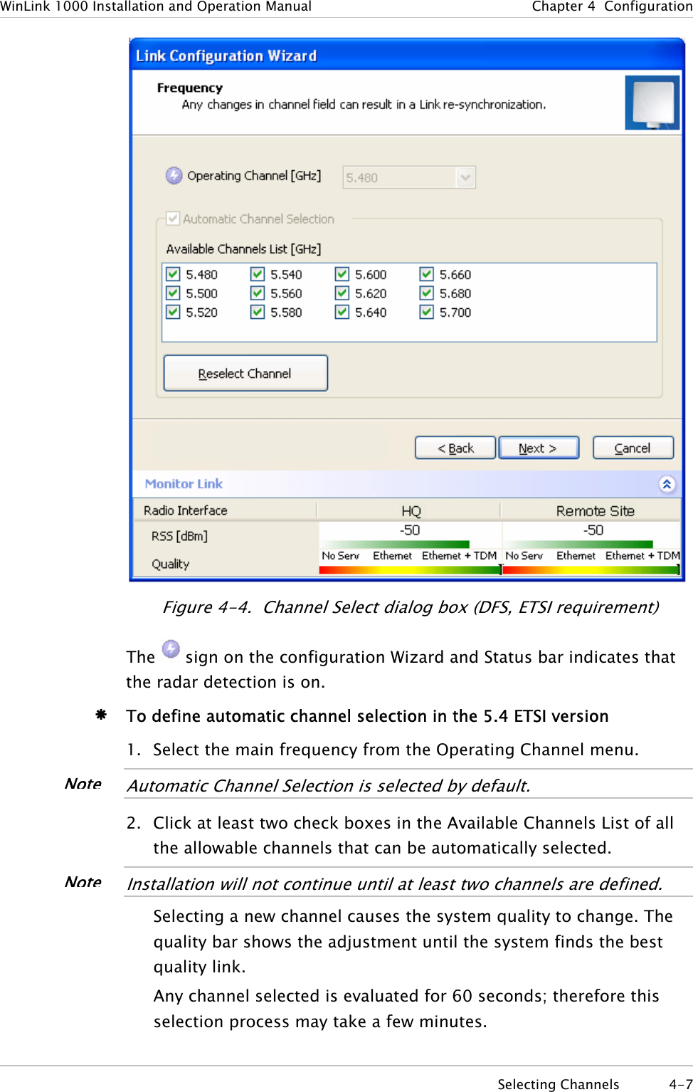
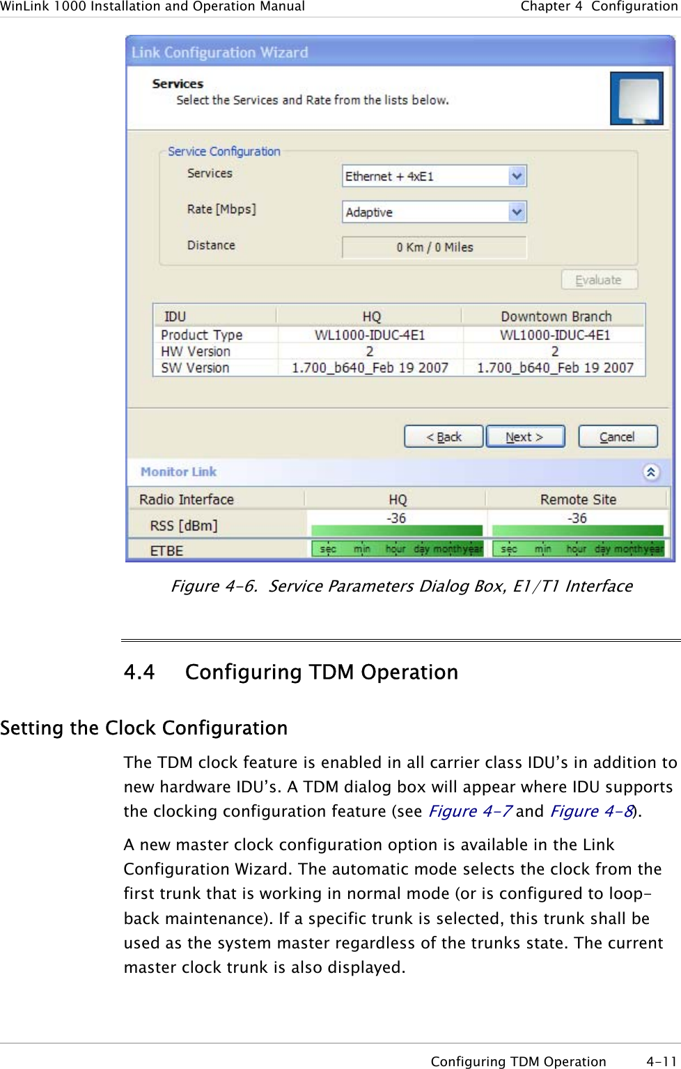
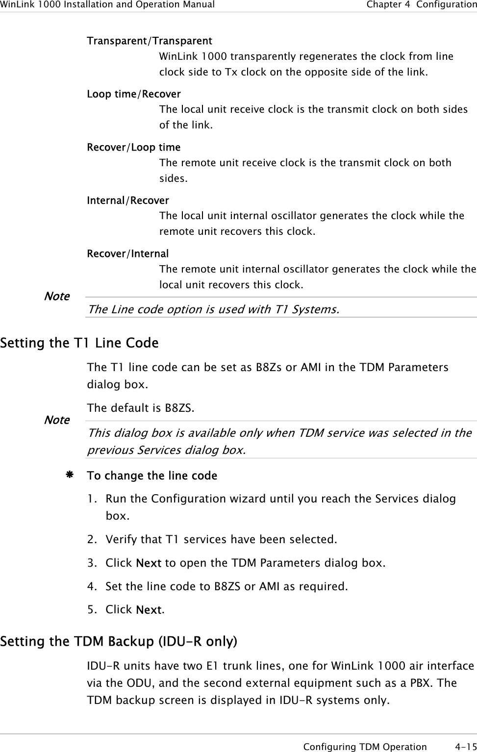
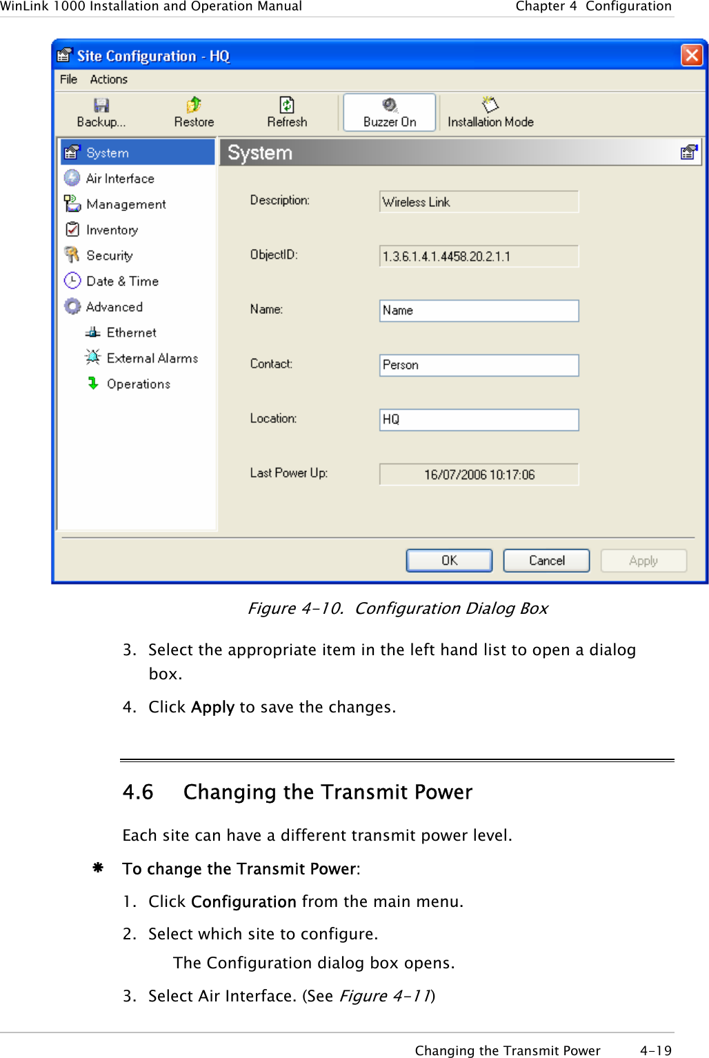
![WinLink 1000 Installation and Operation Manual Chapter 2 Installation and Setup Beeper Sequence =beeper on =beeper off Description [approx. 1s] Best Signal so far Signal quality increased No change in signal Signal quality decreased [approx. 2s] No air link Figure 2-10. Beeper Sequence for ODU Alignment Note• Three beeps and a pause is the best signal Two beeps and a pause, signal quality increased One beep and pause is no signal change Any other signal detects no signal between ODUs. 7. Secure the site A ODU to the mast/wall. 8. At site B, adjust the ODU slowly whilst listening to the beeper sequence until the best signal is attained. 9. Secure the site B ODU to the mast/wall. 10. Monitor the link quality for about 15 minutes to verify stability. 2.13 Calculating the Air Interface Rate The Air Interface rate is the data transmission rate from one site to the other, over the wireless WinLink 1000 interface. Use the Link Budget Calculator Utility in order to calculate the optimal air interface rate and the expected performance of the link operating at the user’s requirements. The ARA, Adaptive Rate Modulation feature performs this task automatically and ensures that the transmission rate is set to maximum whilst the link quality throughput is maintained. Æ To open the Link Budget Calculator Utility 1. Click Help on the Menu Bar. Calculating the Air Interface Rate 2-13](https://usermanual.wiki/Radwin/AMWL1240H.Users-Manual-Part-1/User-Guide-800483-Page-40.png)
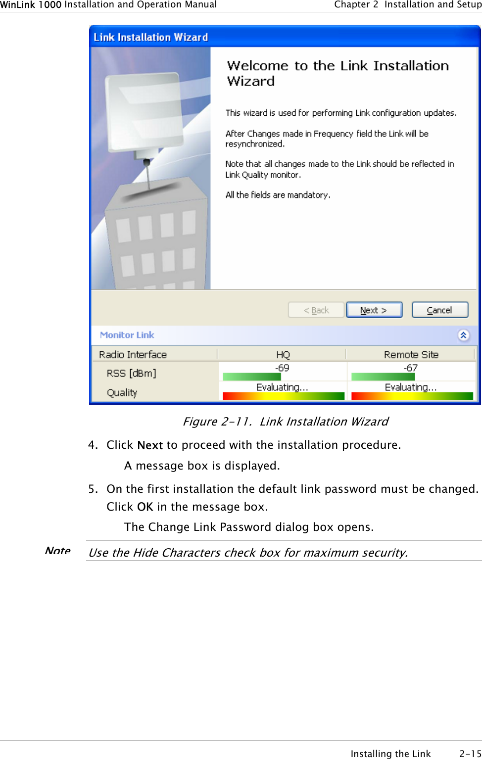
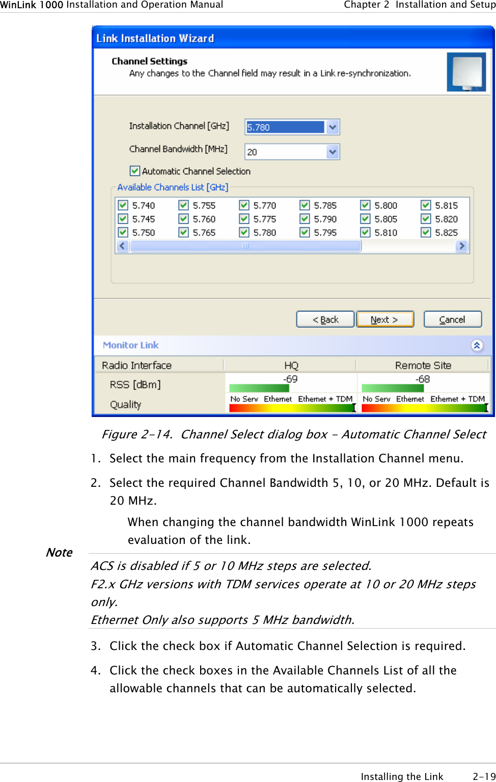
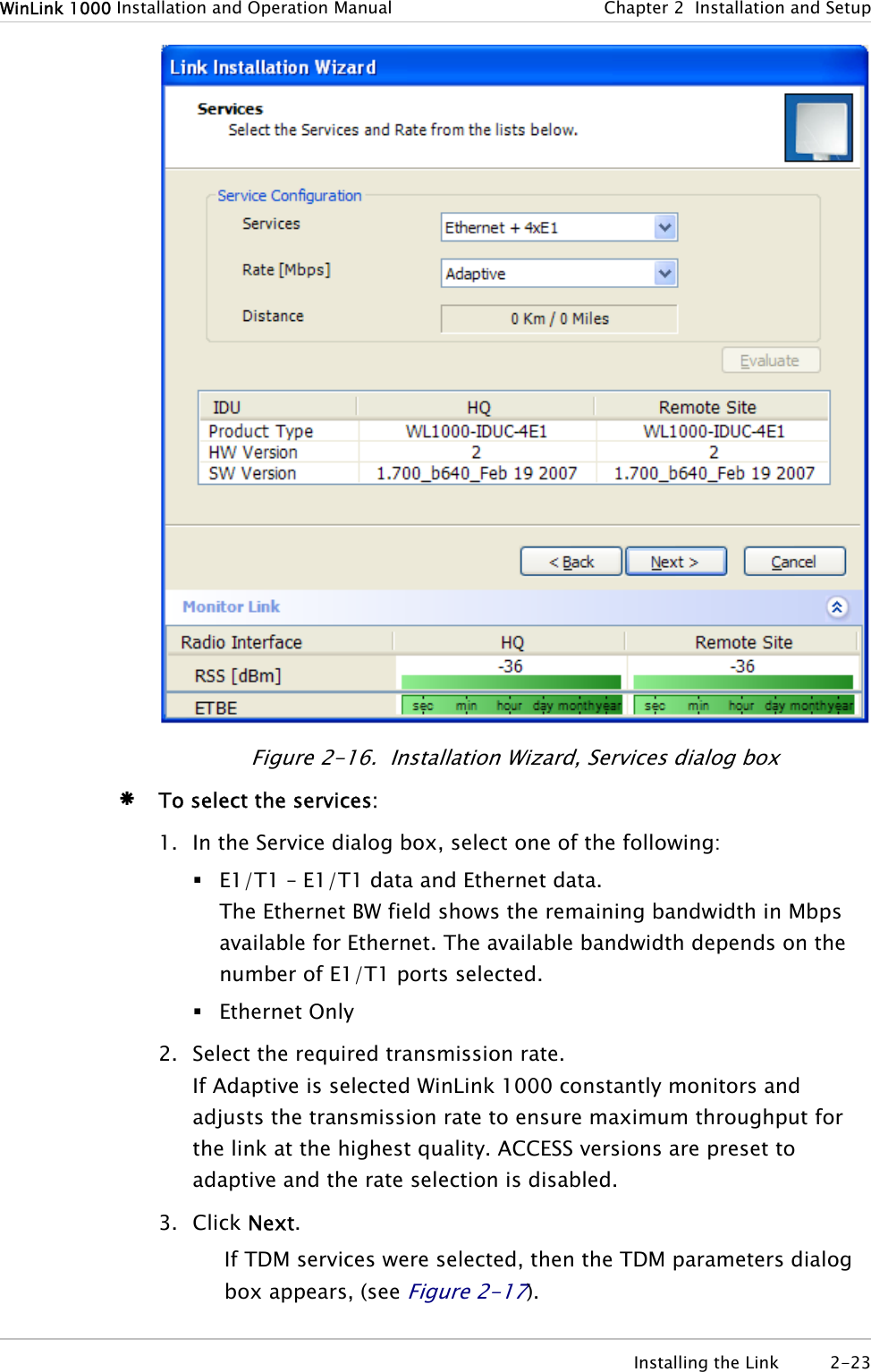
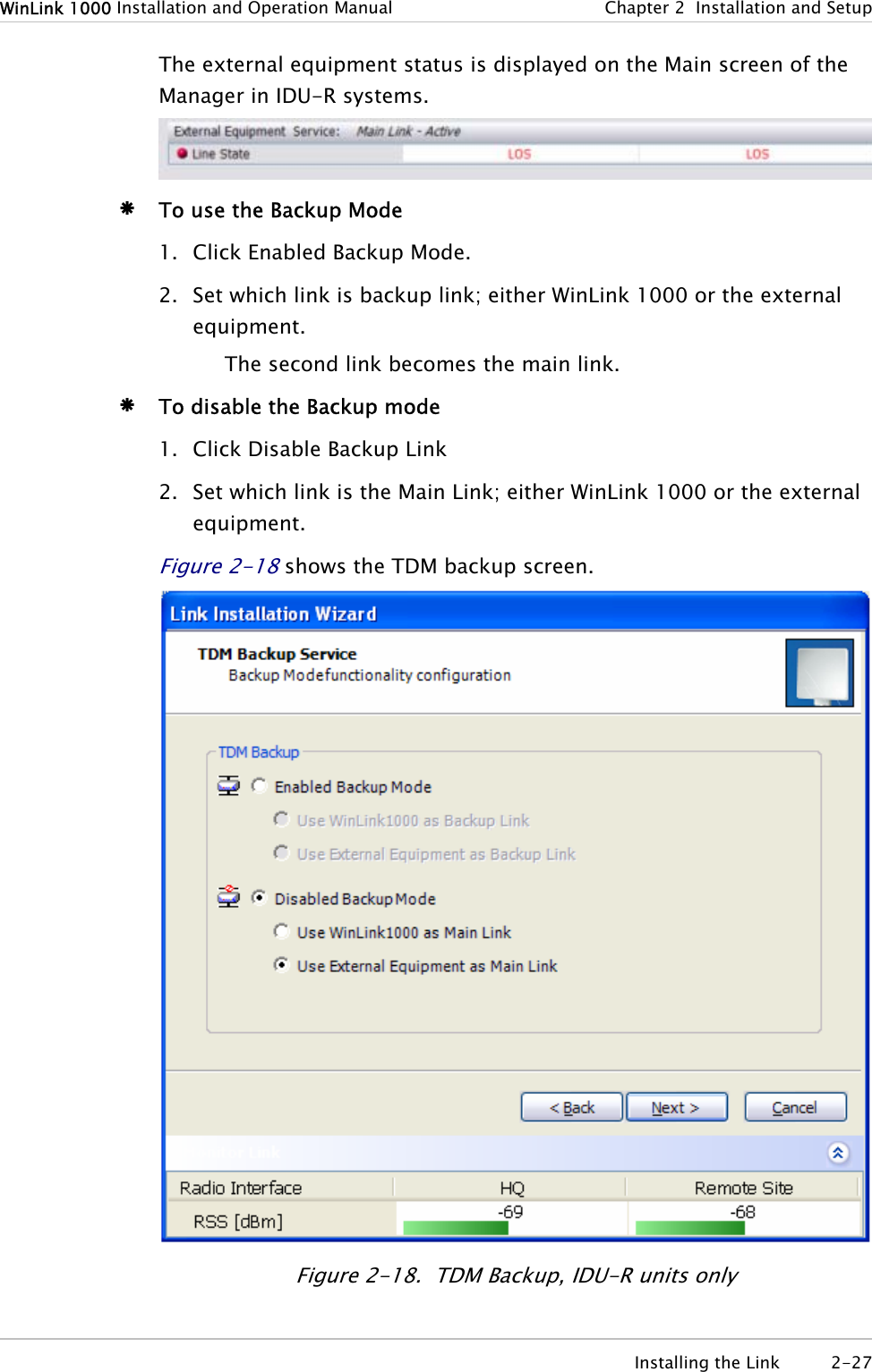
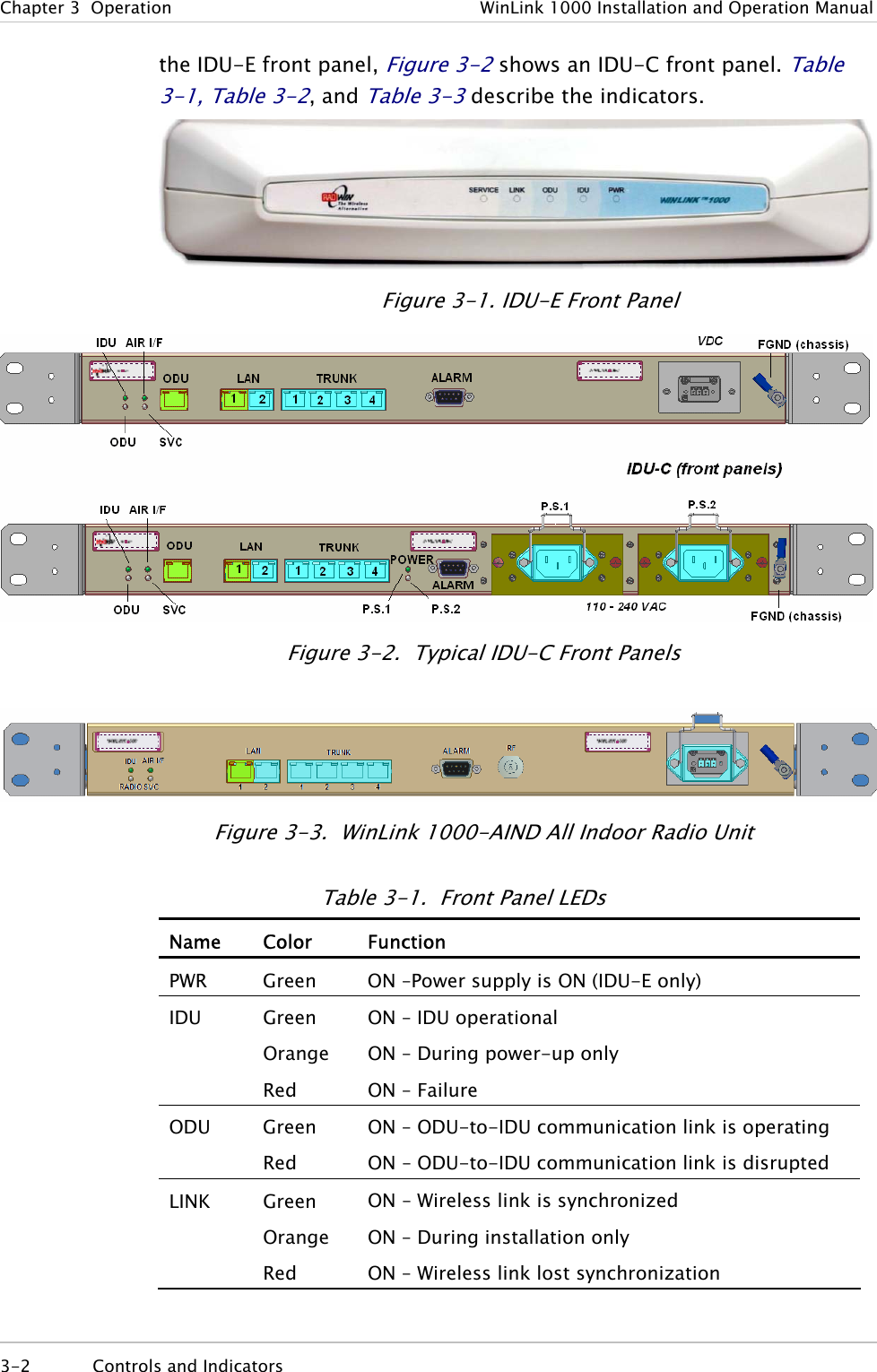
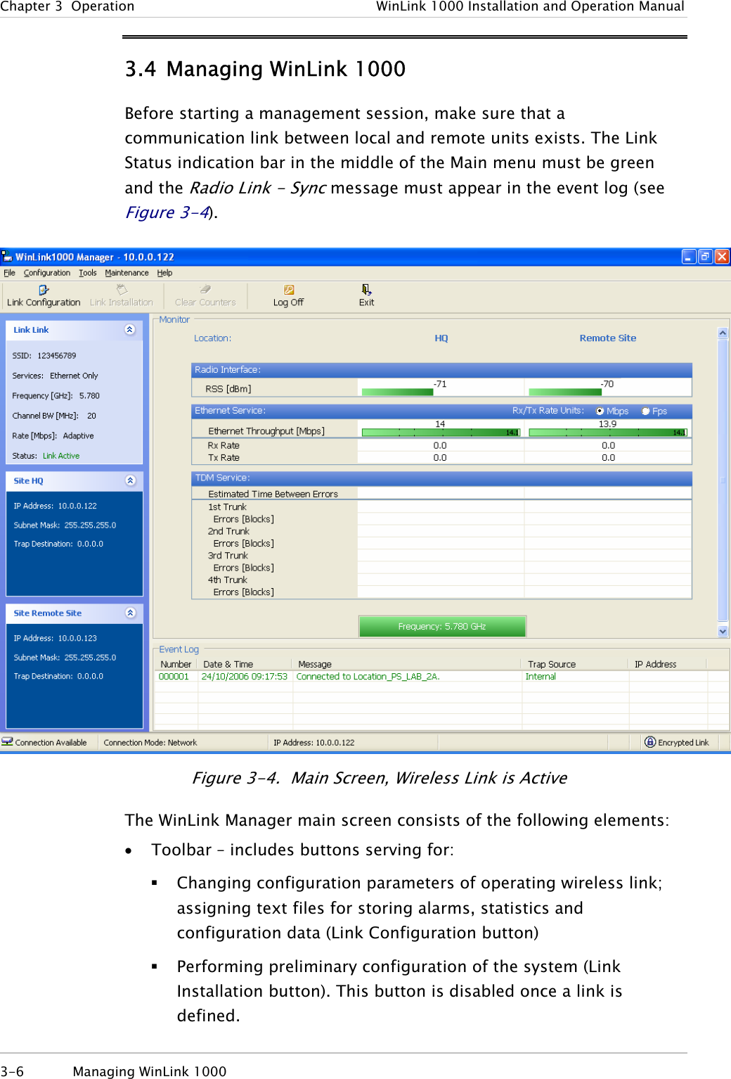
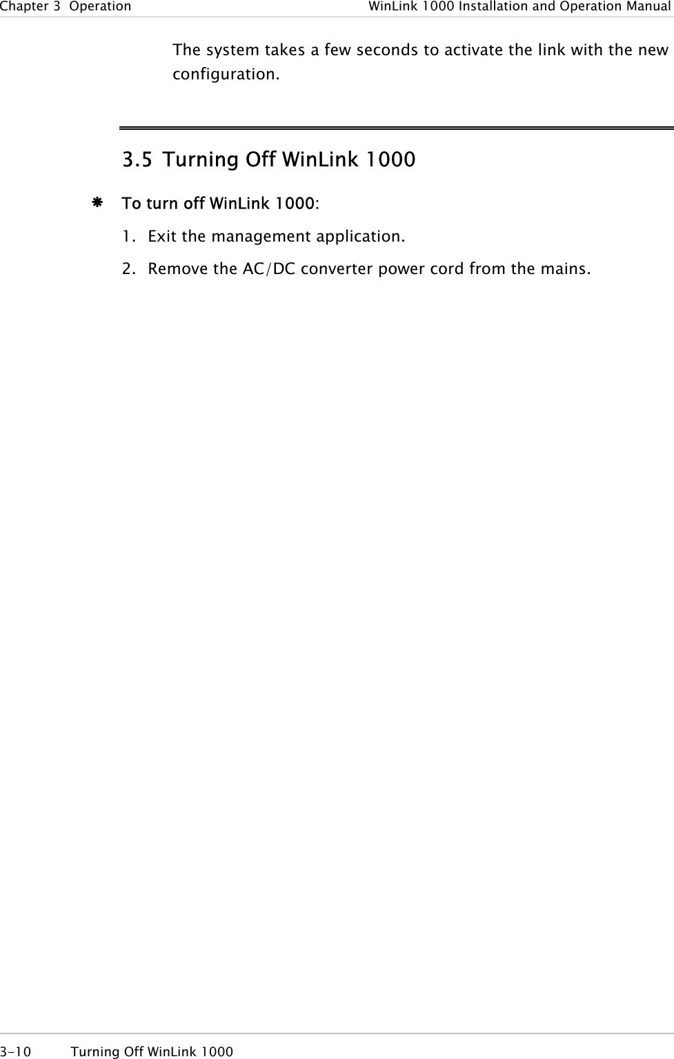
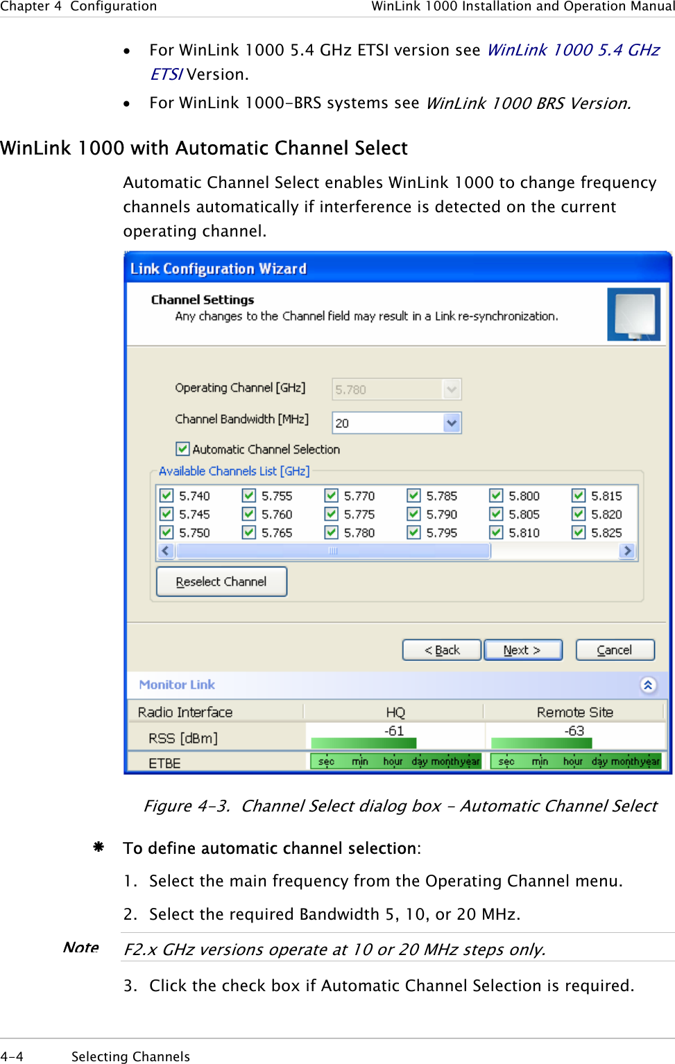
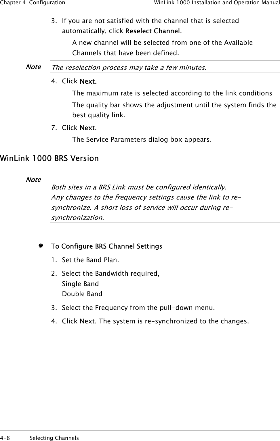
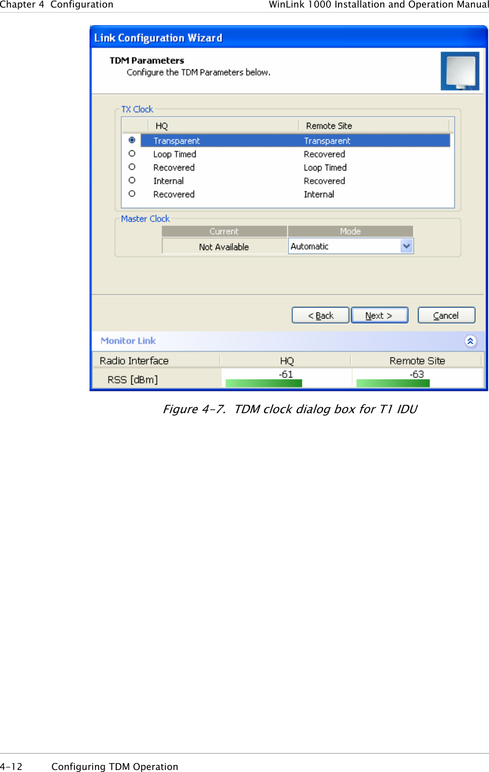
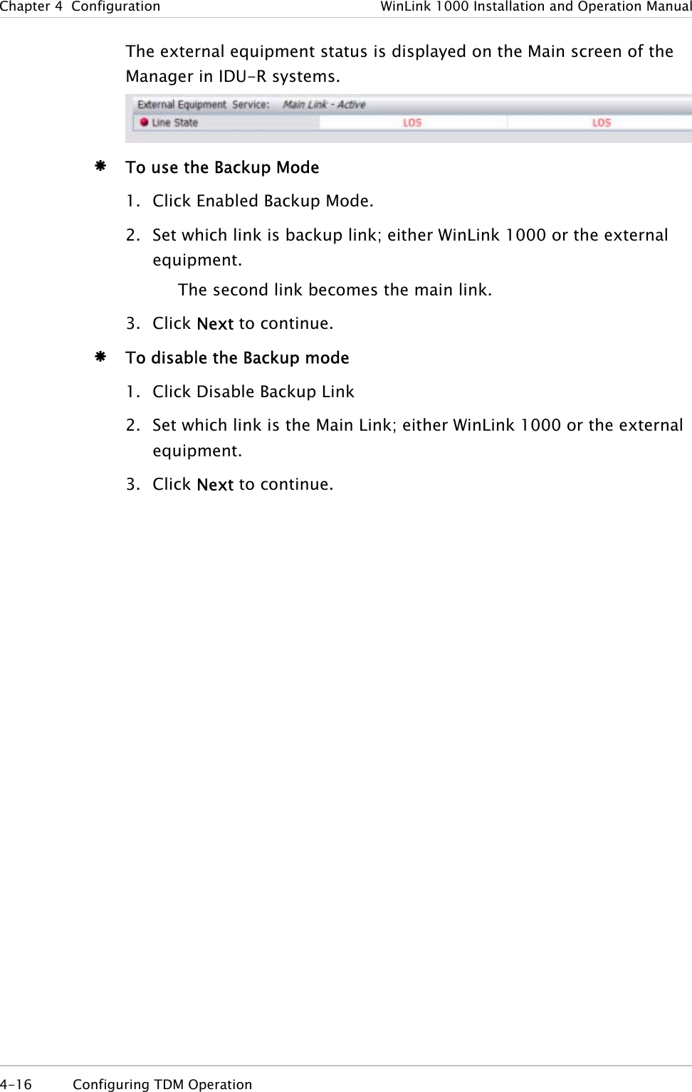
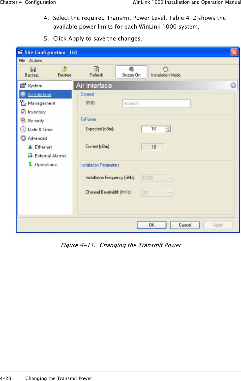
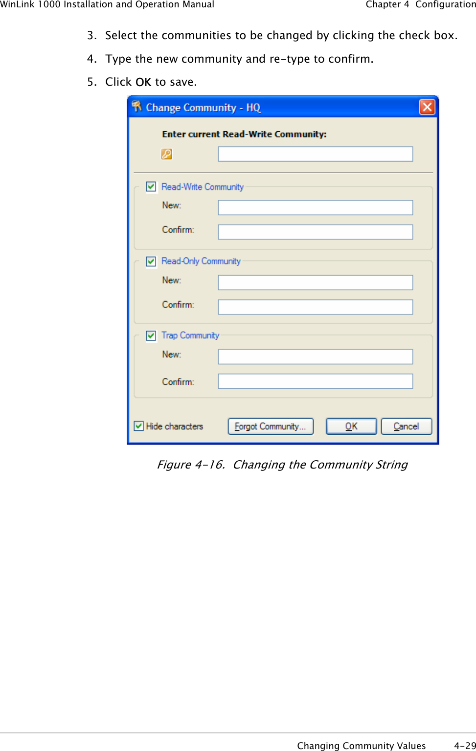
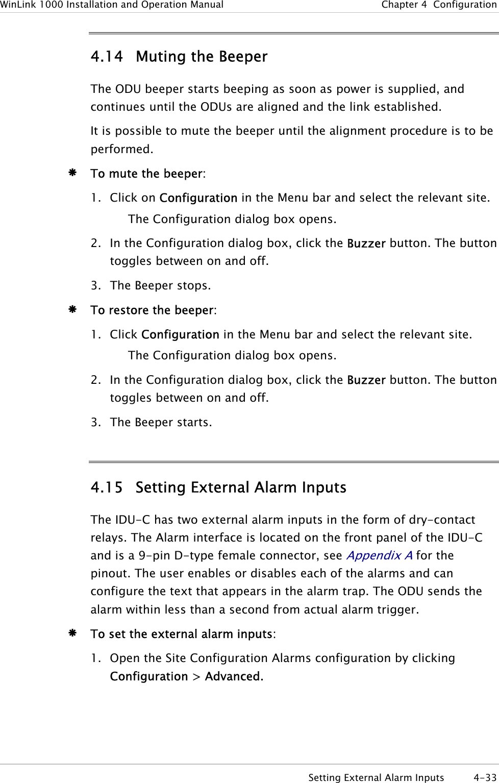
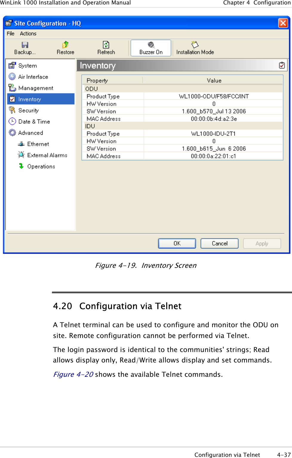
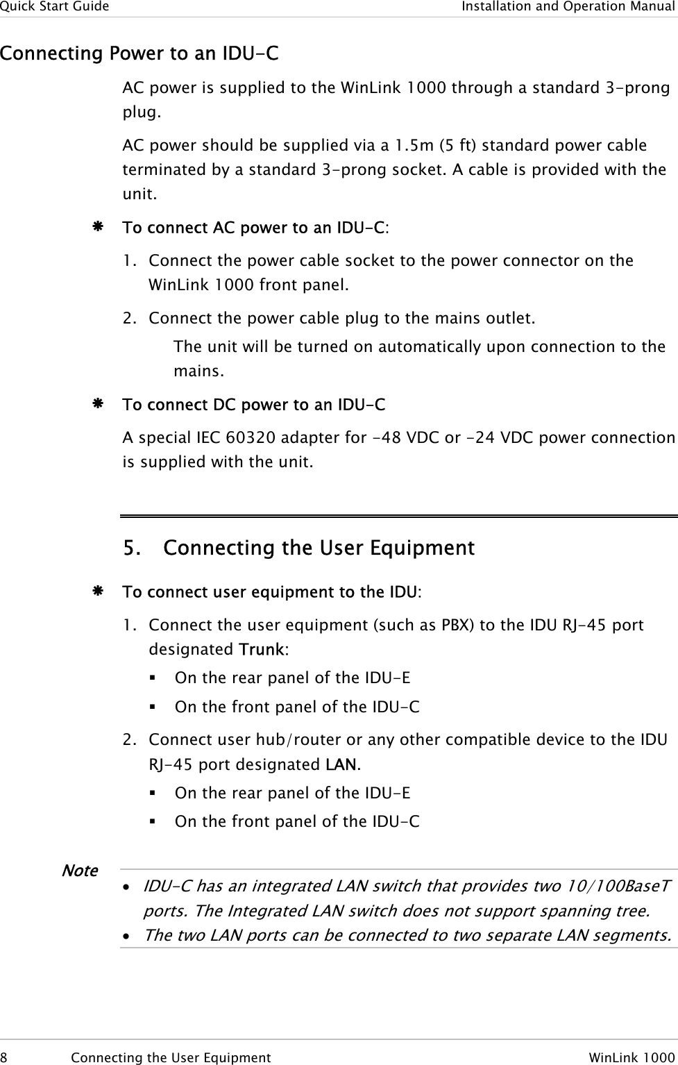
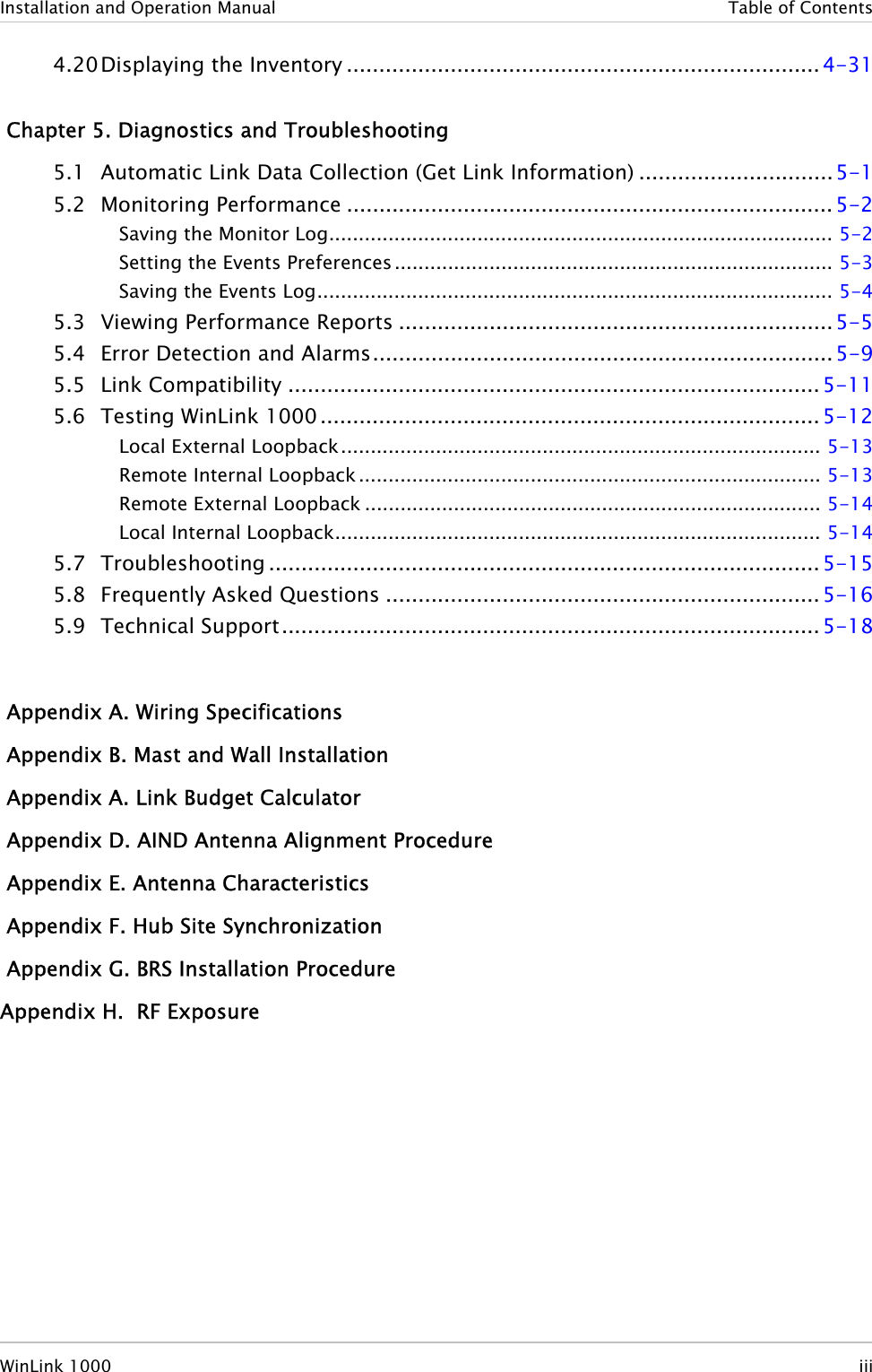
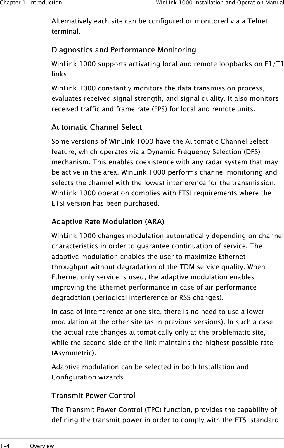
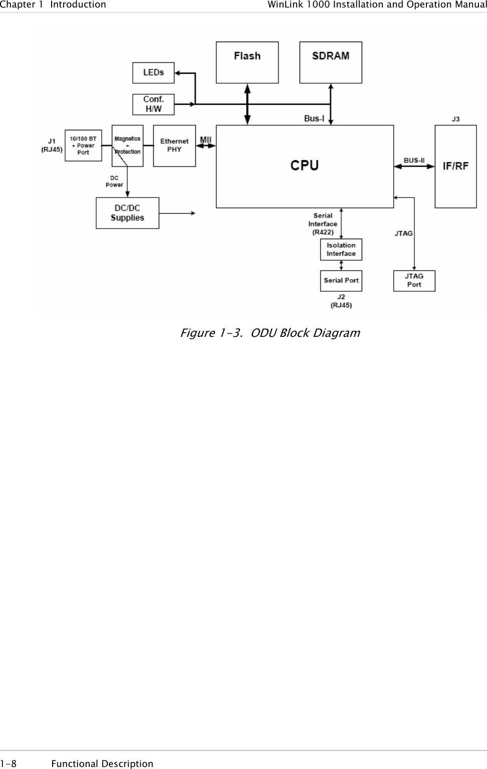
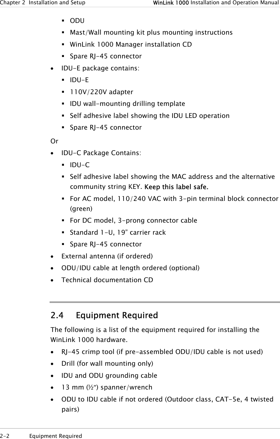
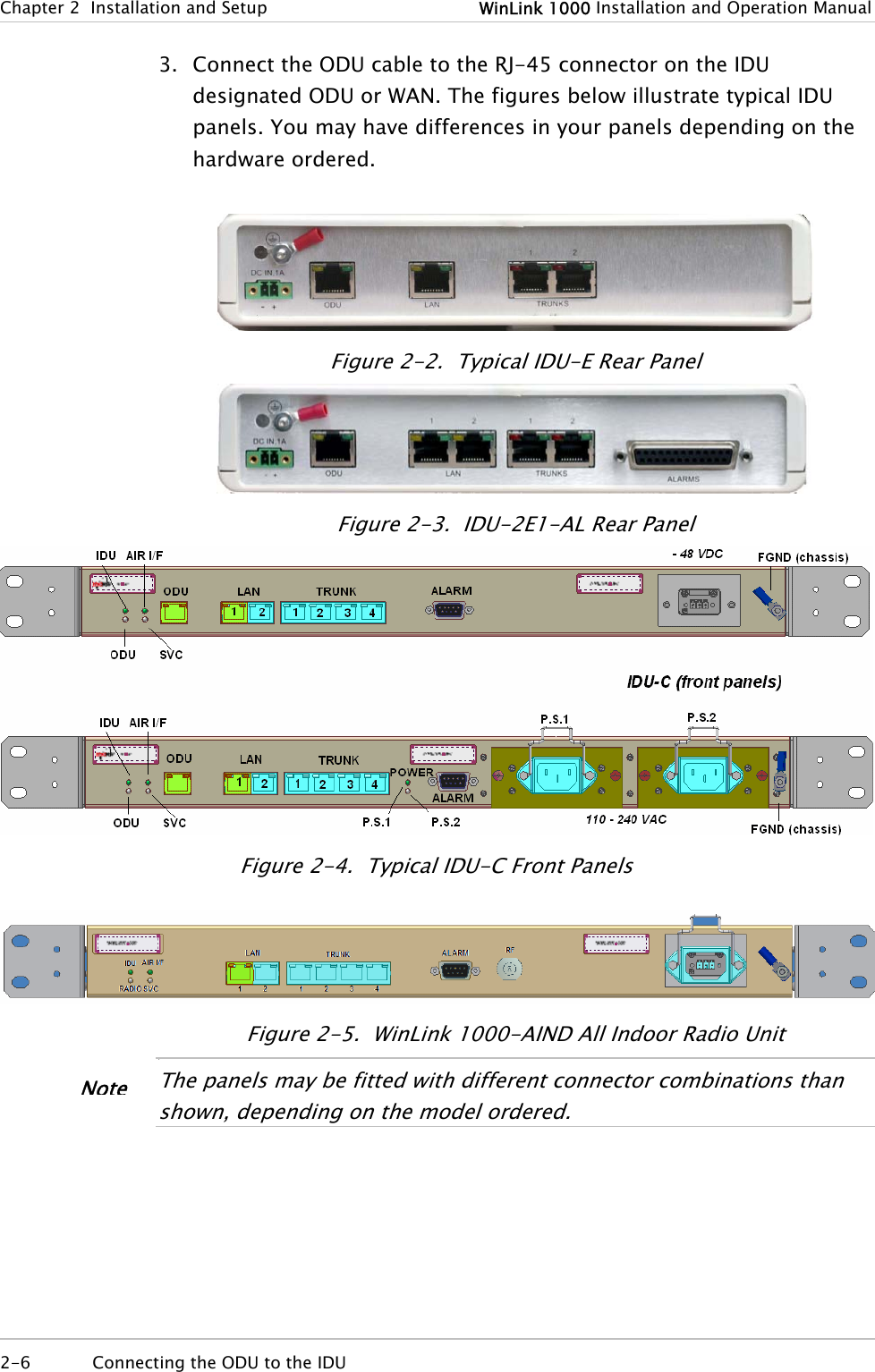
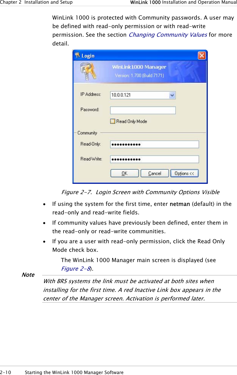
![WinLink 1000 Installation and Operation Manual Chapter 4 Configuration Table 4-2. Typical Transmit Power Limits Regulation Version Min Tx [dB] Max Tx [dB] MaxTx at 36 Mbps [dB] MaxTx at 48 Mbps [dB] Power Control F58 4 16 14 10 Yes F58/EXT 4 16 14 10 Yes F49 14 15 15 14 No F53 -3 8 8 8 Yes F53/EXT 3 3 3 3 No F24 18 18 18 18 No FCC F53HP 10 16 14 10 Yes F54 2 8 8 8 Yes F54/ETSI 2 8 8 8 Yes ETSI F54-HG/EXT -3 3 3 3 Yes 4.7 Defining the Management Addresses Each site must be configured separately, first site A then site B. Æ To define the Management Addresses: 1. Click Configuration from the main menu. 2. Select which site to configure. The Configuration dialog box opens. 3. Select Management (see Figure 4-12). 4. Enter the IP address of the ODU in the IP address field. NoteIf performing configu ation from the WinLink manager, the IP address is entered in the login screen (rFigure 2-4) 5. Enter the Subnet Mask. 6. Enter the Default Gateway. Defining the Management Addresses 4-21](https://usermanual.wiki/Radwin/AMWL1240H.Users-Manual-Part-1/User-Guide-800483-Page-87.png)