Radwin AMWL1240H ODU User Manual Part 2
Radwin Ltd. ODU Users Manual Part 2
UserManual.wiki
>
Radwin
>
AMWL1240H User Manual
>
Users Manual Part 2
Contents
1.
Users Manual Part 1
2.
Users Manual Part 2
Users Manual Part 2
Navigation menu
Upload a User Manual
Namespaces
Wiki Guide
HTML
PDF
Info
Views
User Manual
Discussion / Help
Navigation
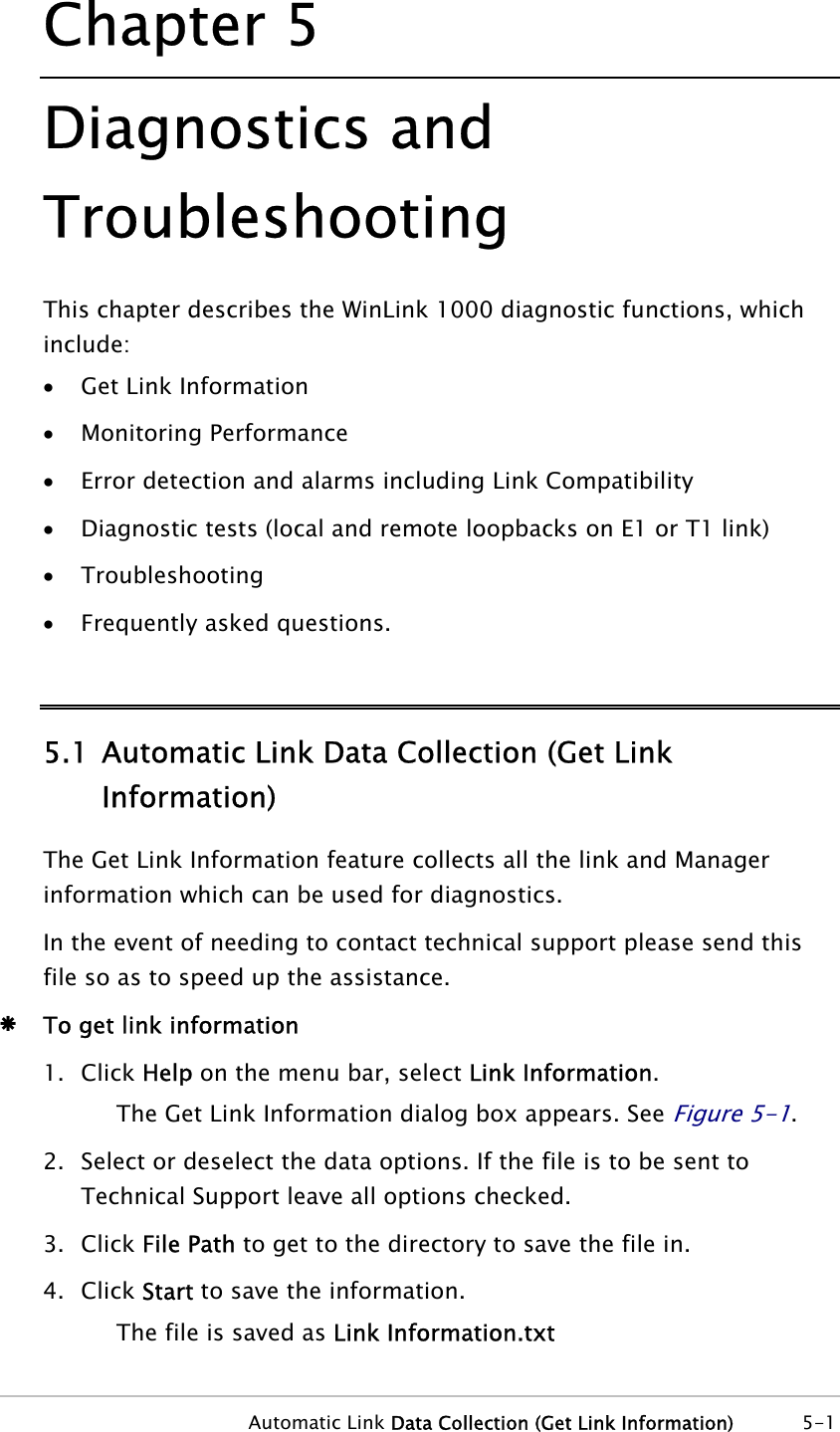
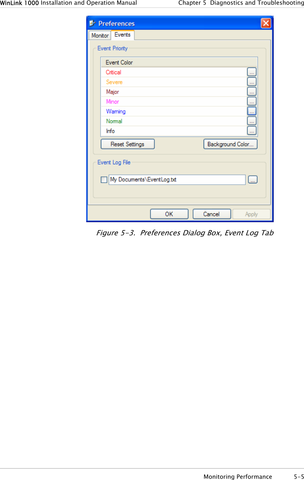
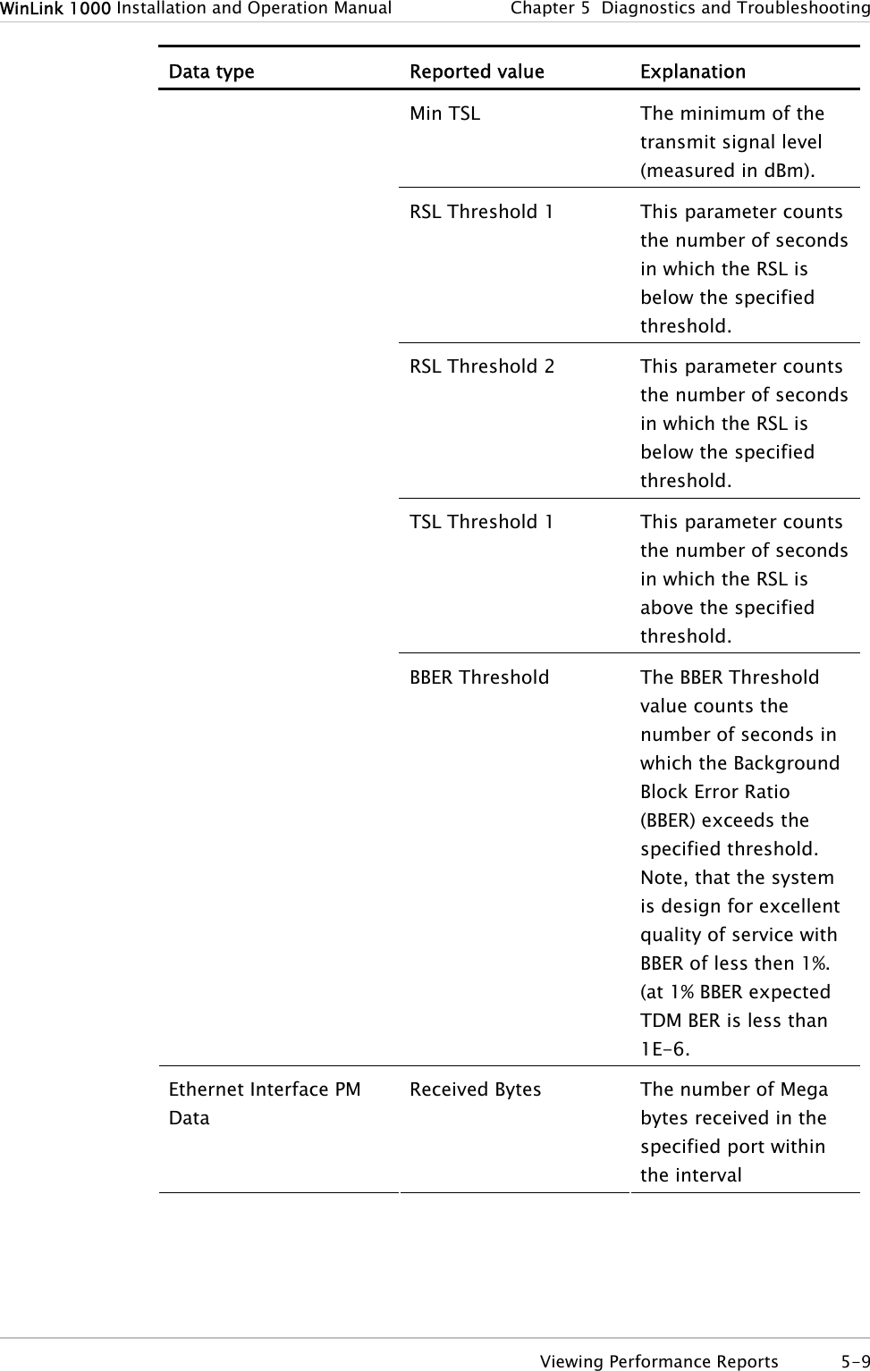
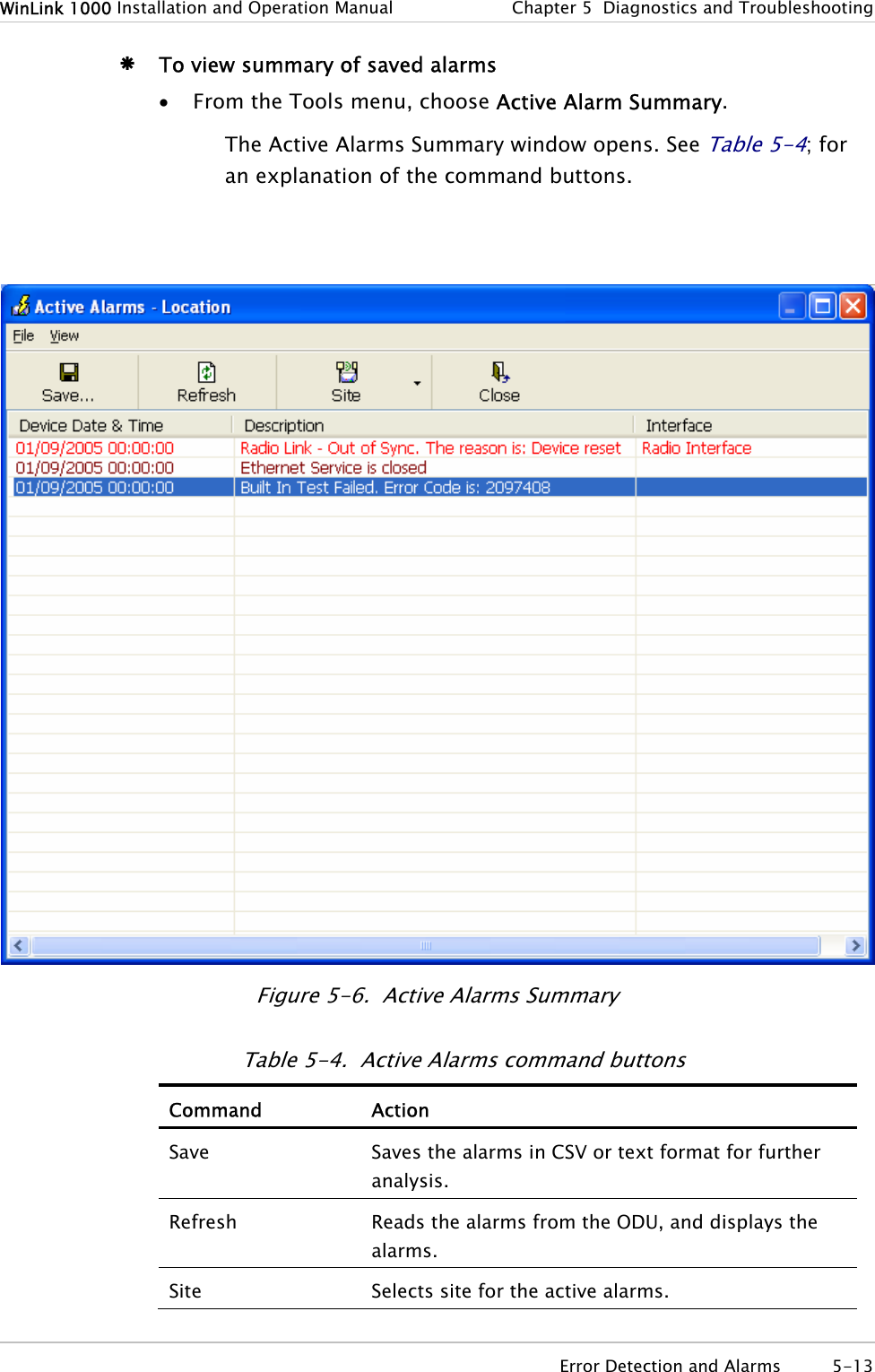
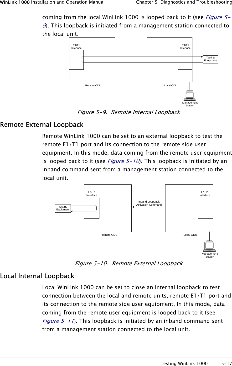
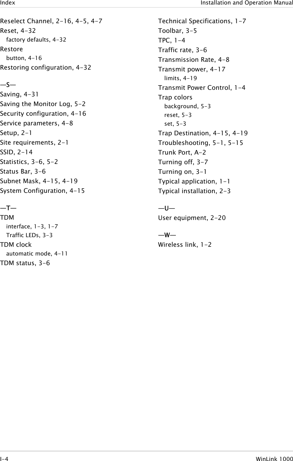
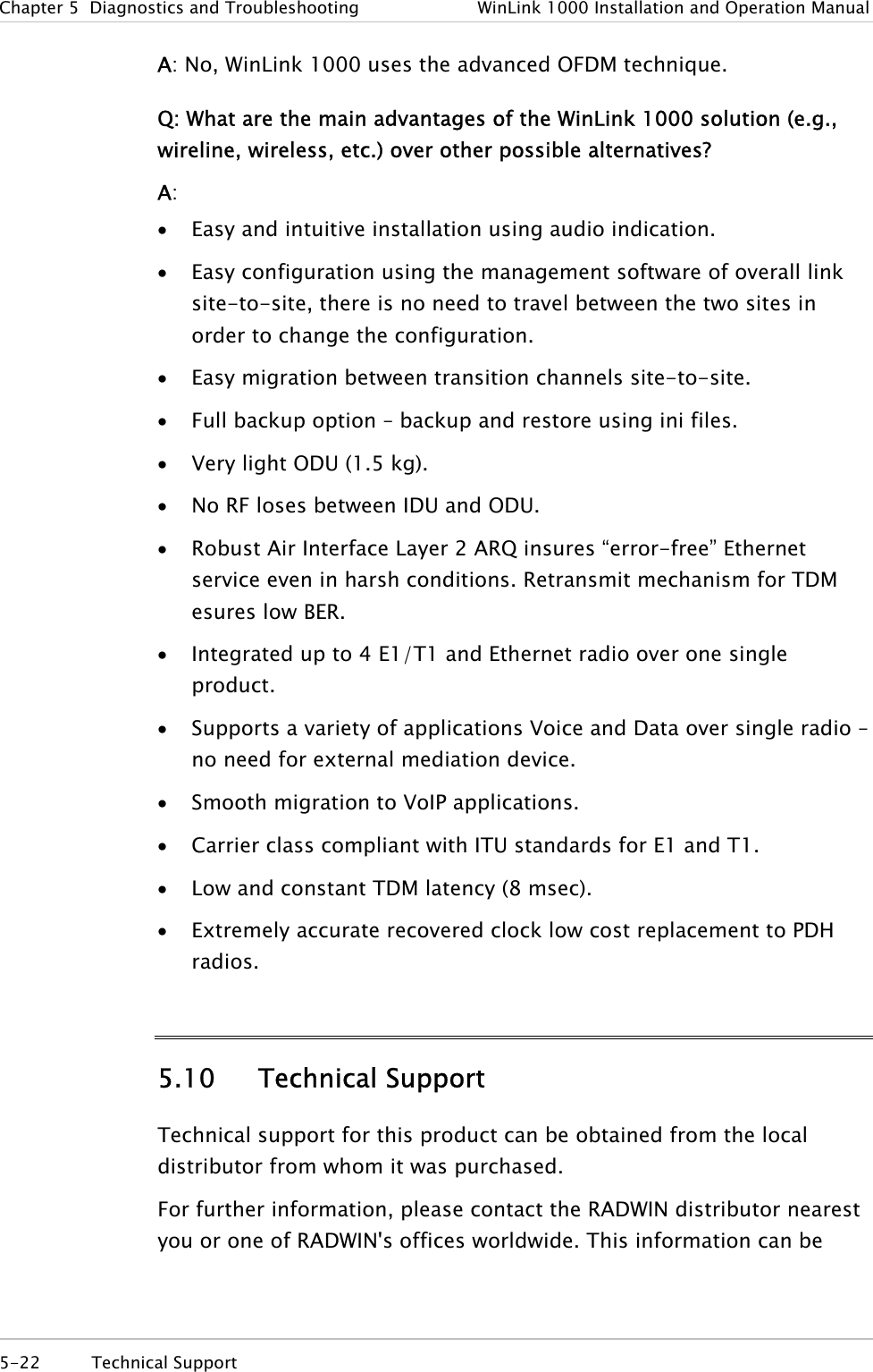
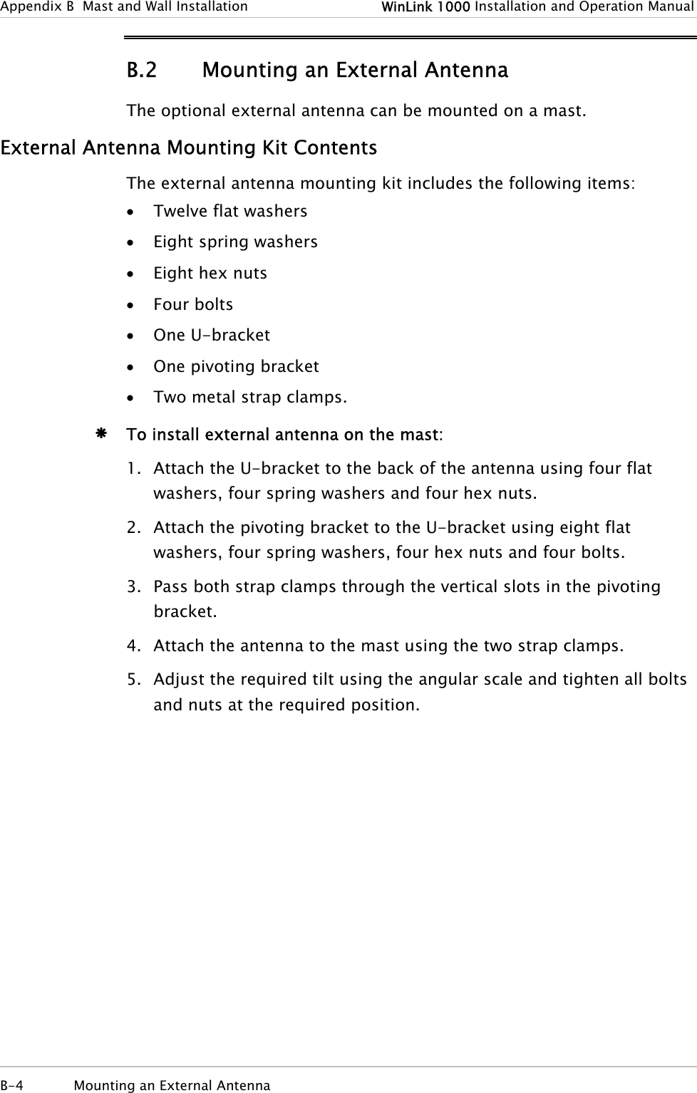
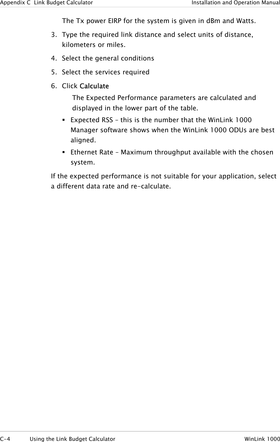
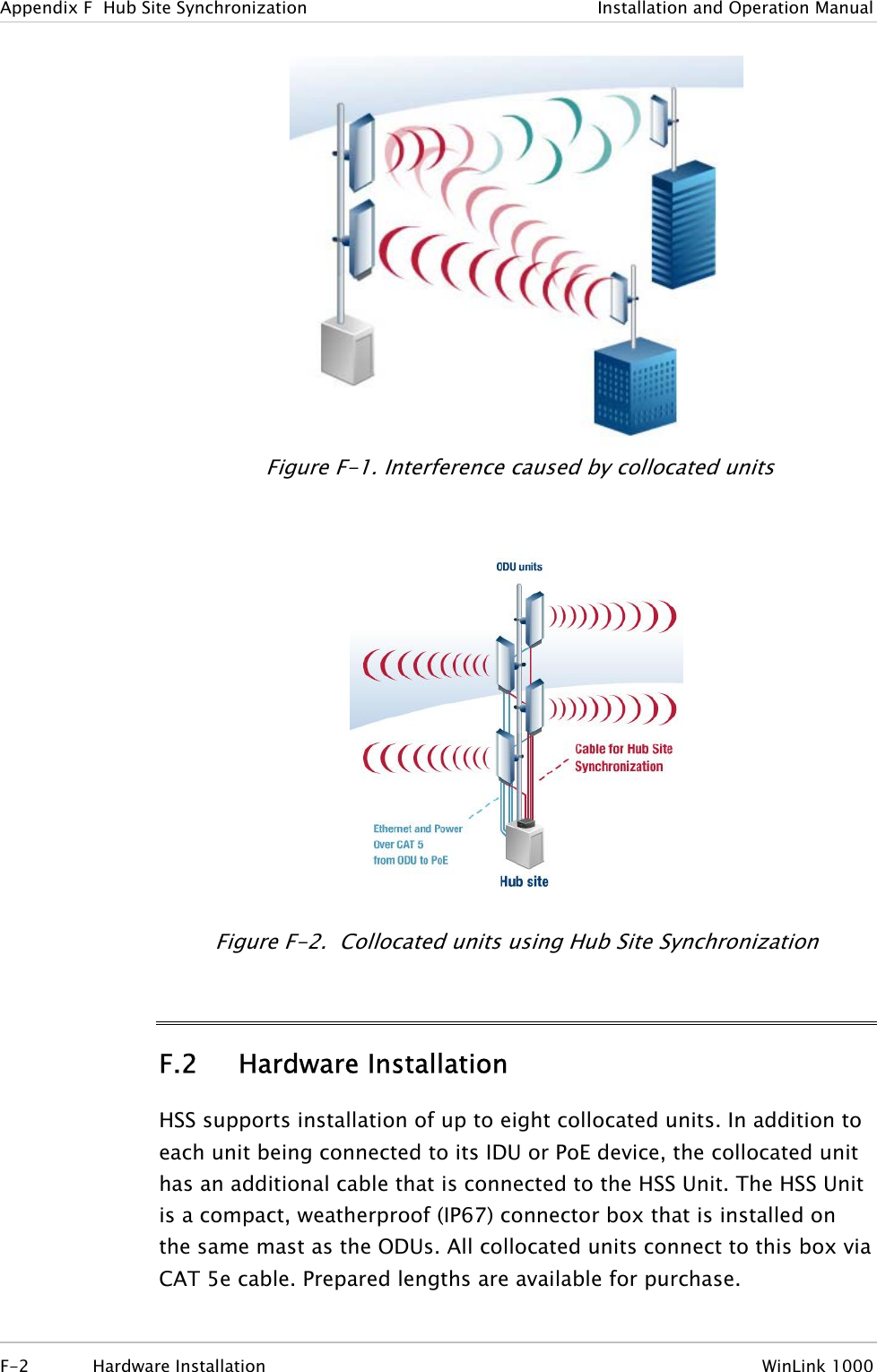
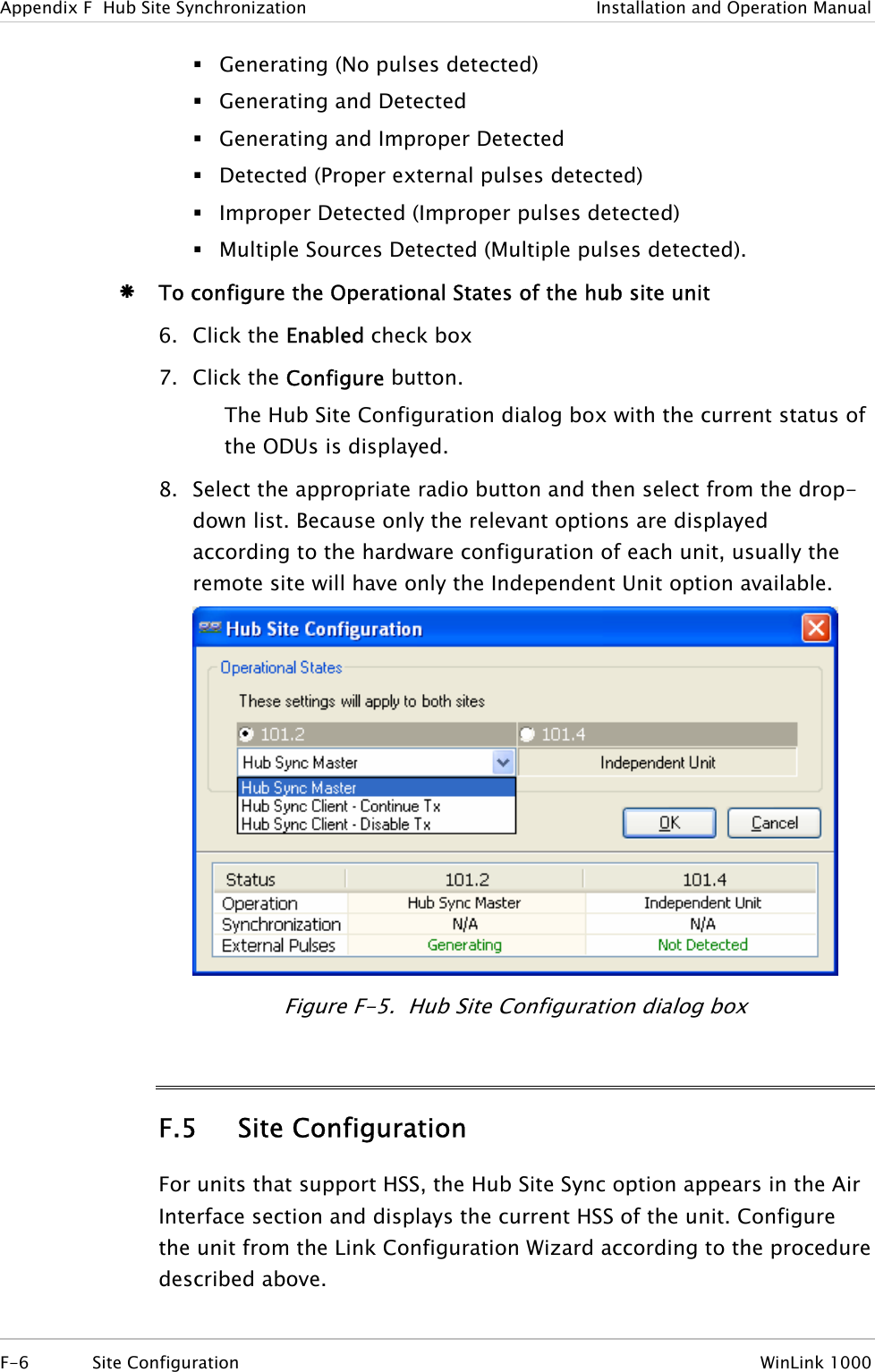
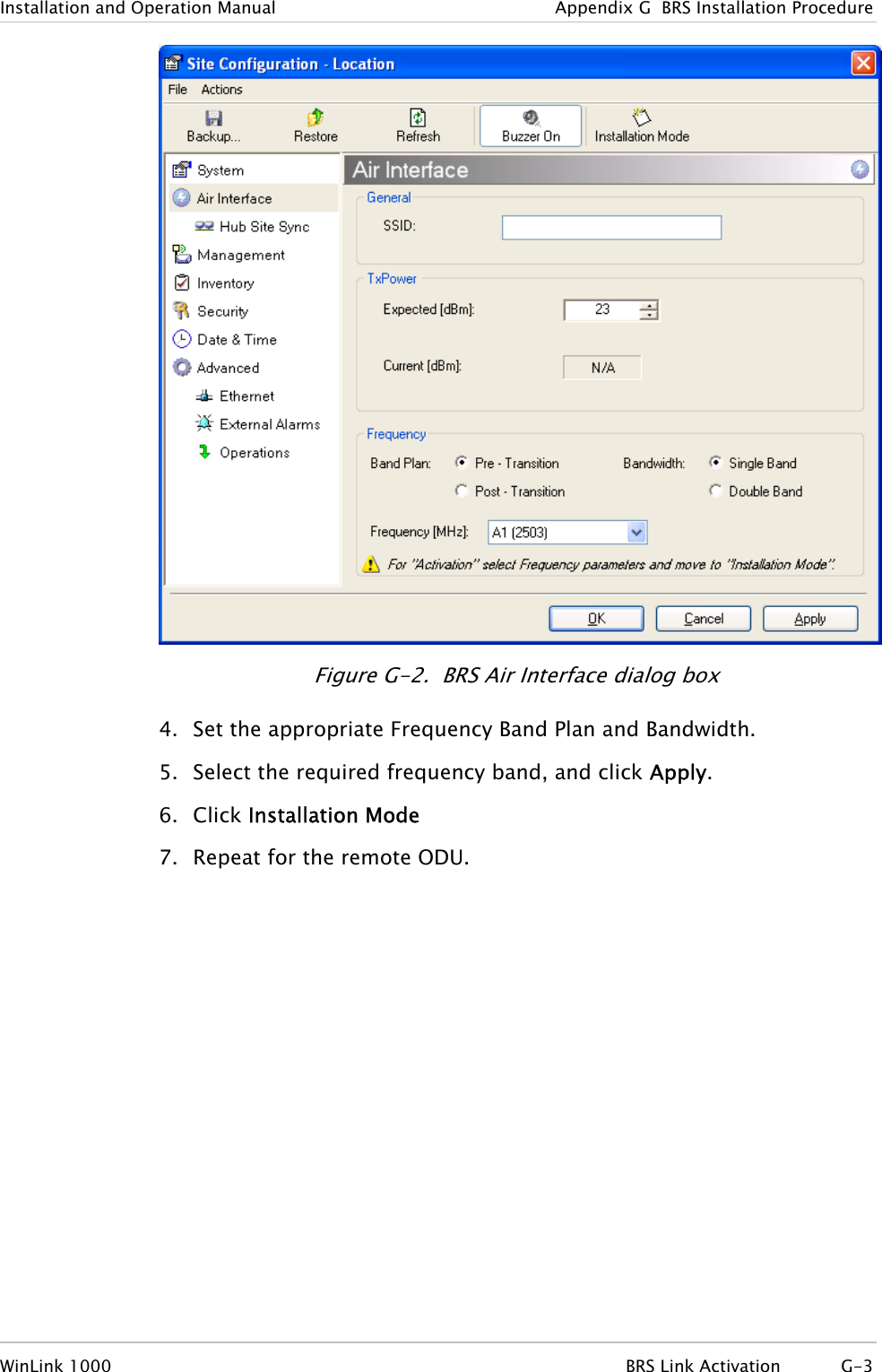
![WinLink 1000 Installation and Operation Manual Chapter 5 Diagnostics and Troubleshooting authorized with its specific external ODU product can be used. That is given that it can be cascaded to our external unit. Please note that dB losses in the cascading cable between the external ODU and antenna should be taken into consideration. (In the supplied cascading cable of one meter we have 1 dB loss) Q: Do we need to add external arrestors on WinLink 1000 cables? A: The WinLink 1000 ODU includes arrestors and lightning protection. Therefore there is no need to add additional arrestors. Q: What is the actual Ethernet data rate and maximum throughput? A: The maximum net throughput of WinLink 1000 is full duplex 18 Mbps. NoteWinLink 1000 is a symmetrical system Q: What is the sensitivity for each rate of the WinLink 1000? A: The rate sensitivities are: Rate [Mbps] Sensitivity [dB] 12 -84 18 -81 36 -74 48 -68 Q: Does WinLink 1000 withhold any MAC Addresses? A: The WinLink 1000 is a layer 2 Bridge (VLAN transparent). The built-in switch contains a MAC Address table up to 2047. Q: Can I use any category 5e cable in order to connect the IDU and ODU? A: The cable should be suitable for outdoor use, and shielded Category 5e. Q: What are the BER values expected in the WinLink 1000 link? A: 10-11 (according to BER sensitivity threshold) Q: Does WinLink 1000 use DSSS technique? Frequently Asked Questions 5-21](https://usermanual.wiki/Radwin/AMWL1240H.Users-Manual-Part-2/User-Guide-800484-Page-21.png)

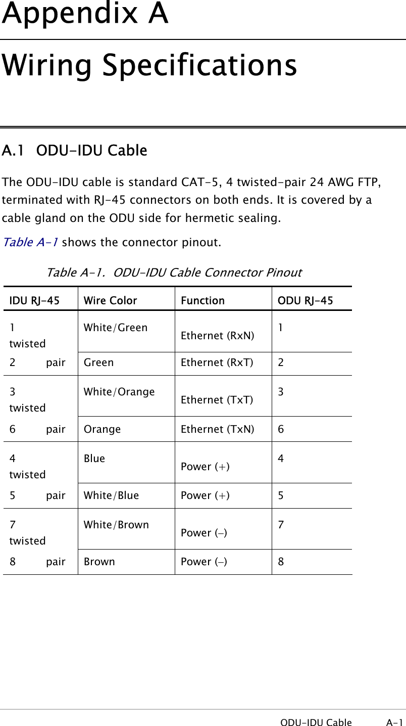

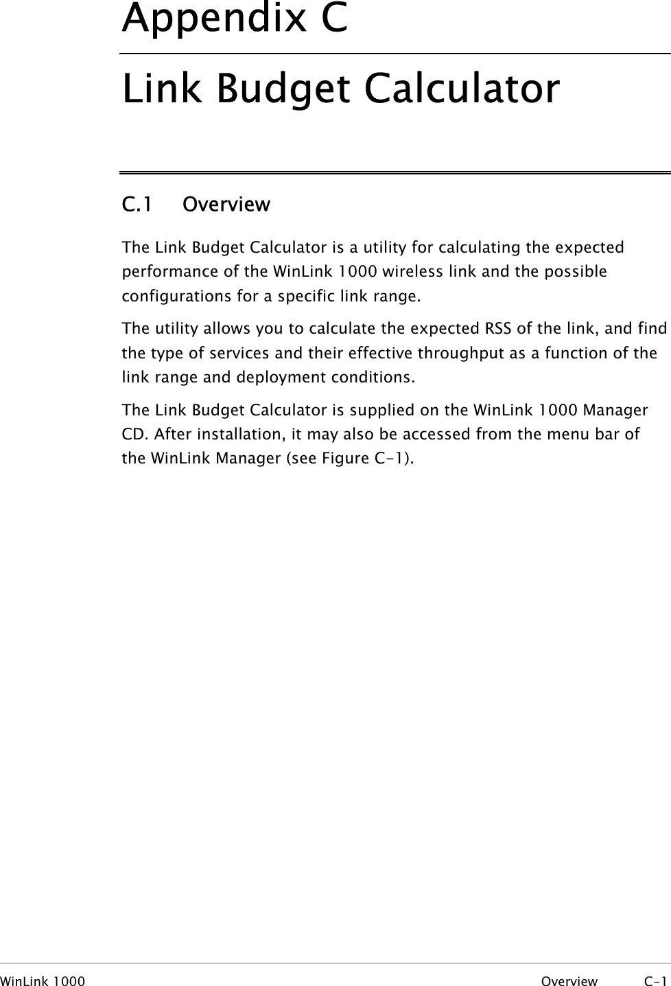
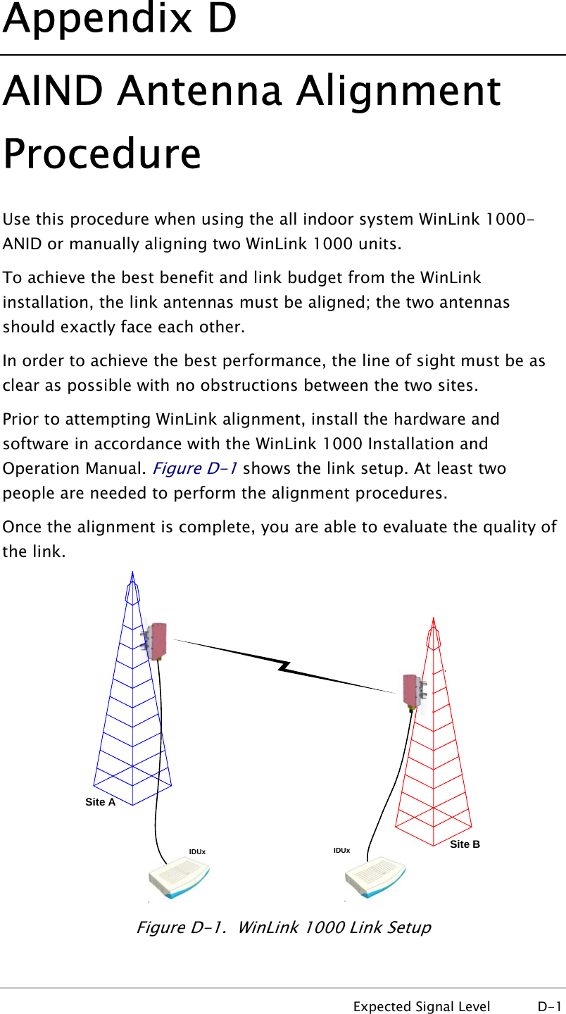
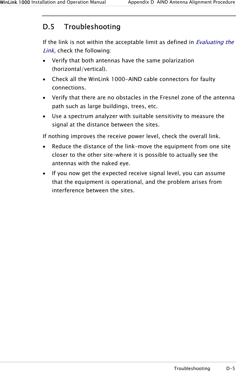
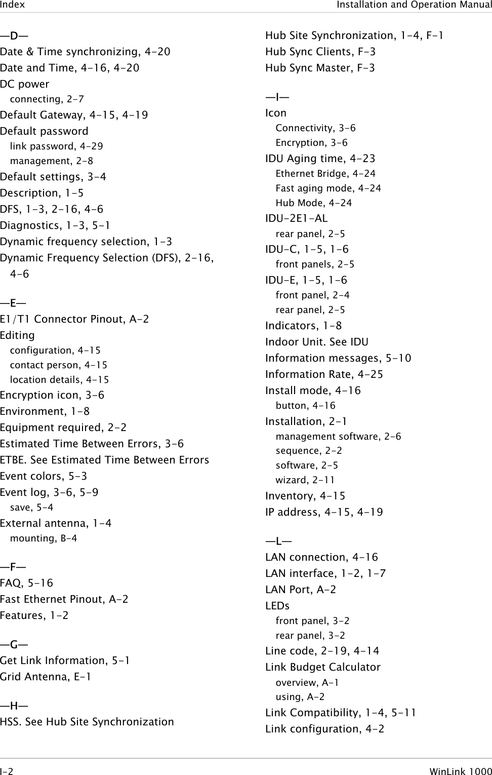
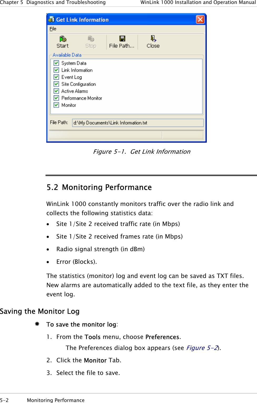
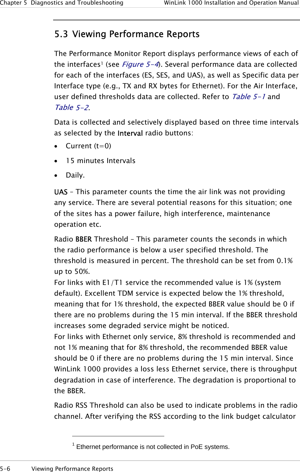
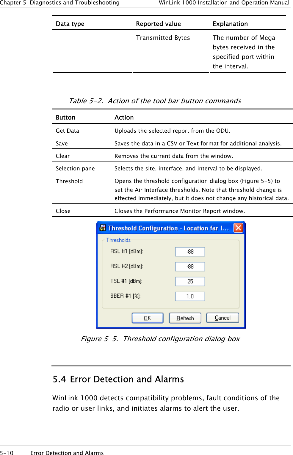
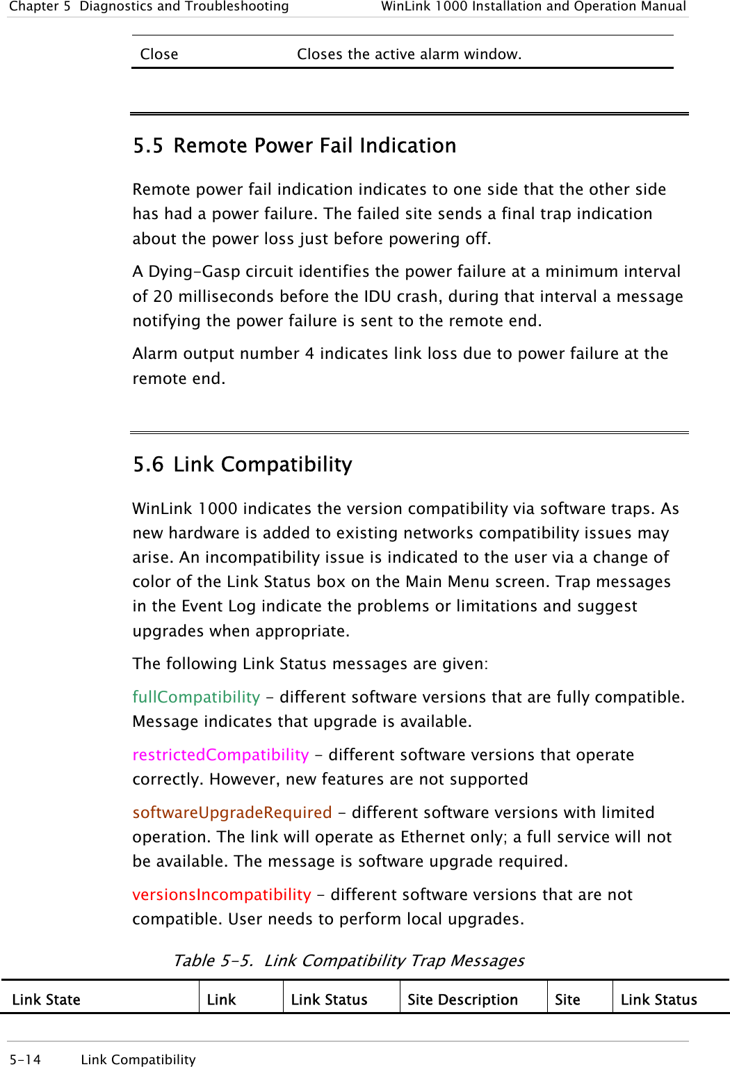
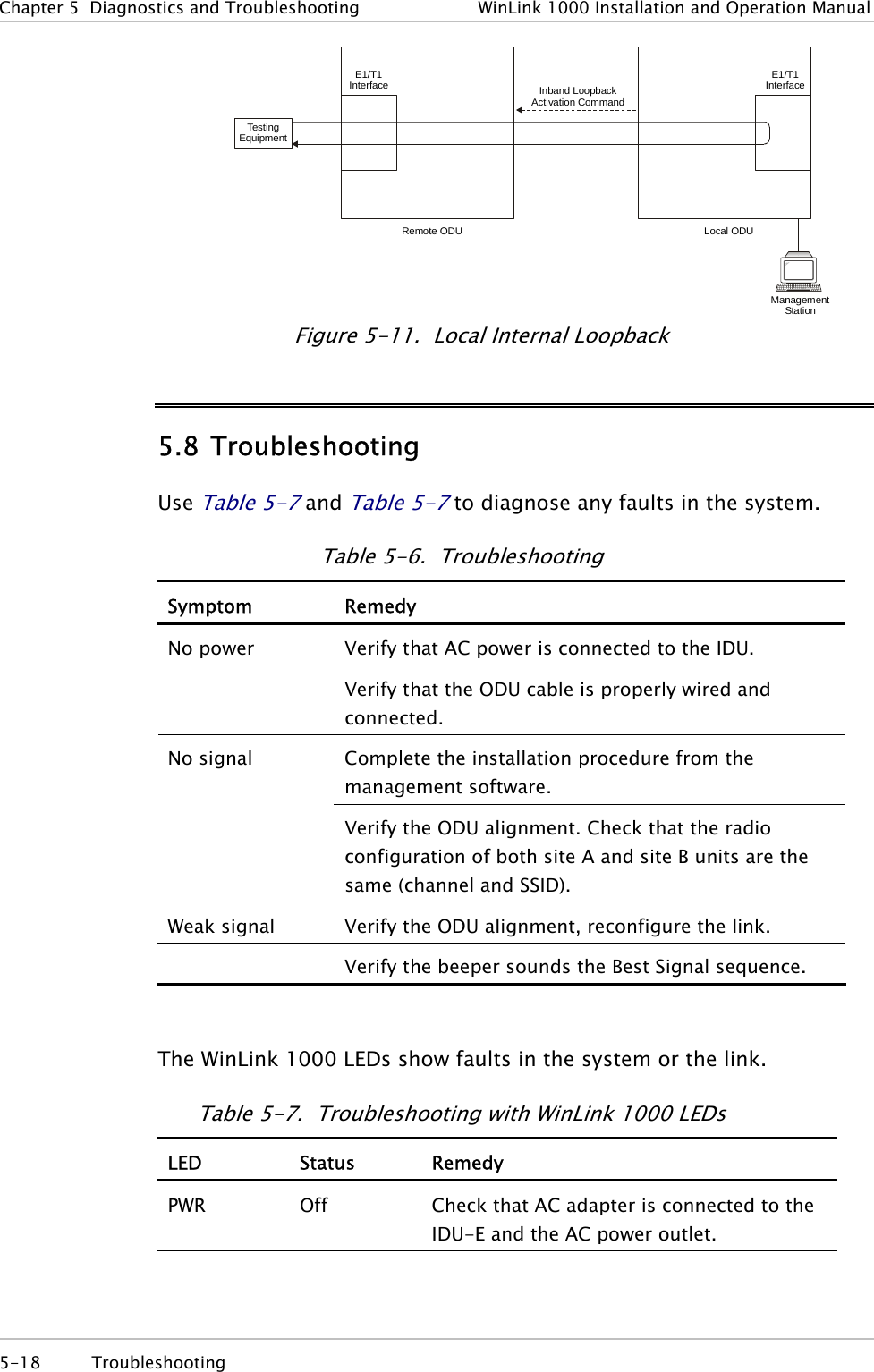
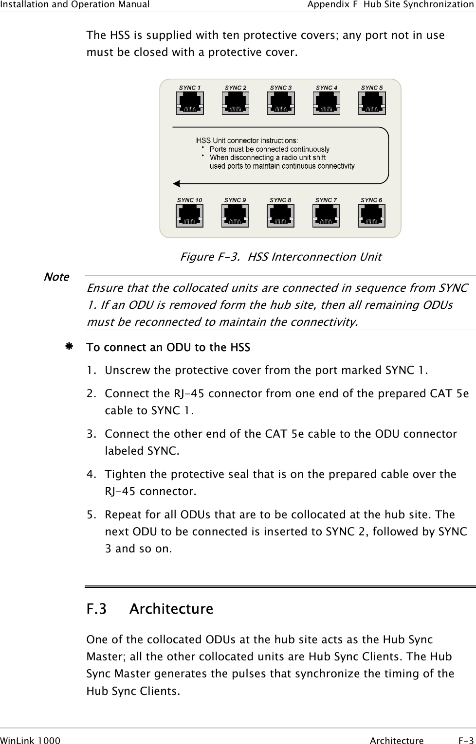
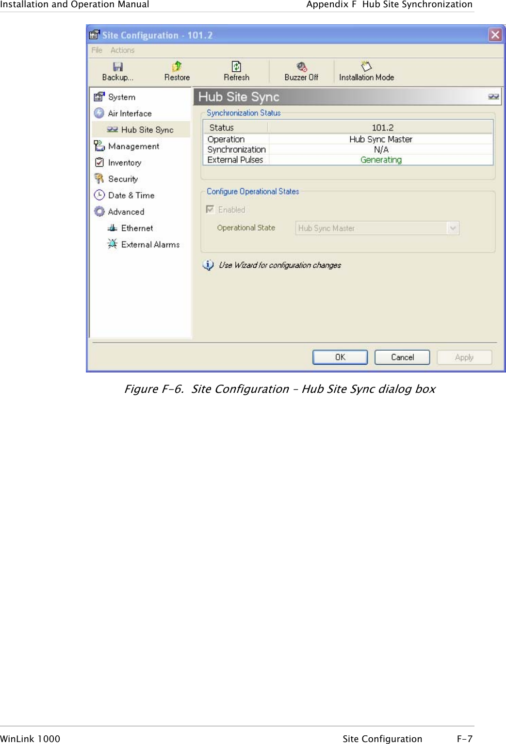
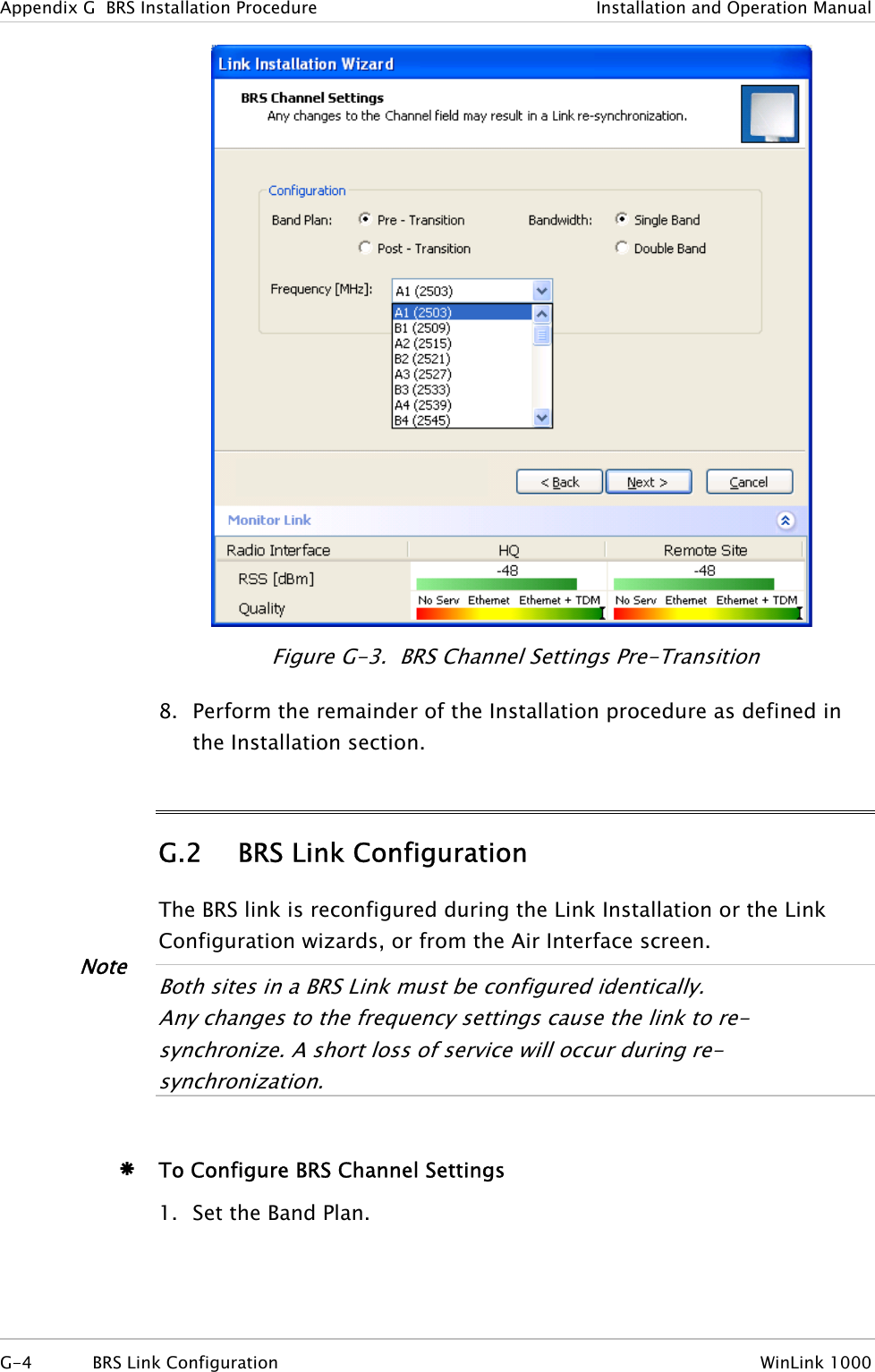
![Appendix E Antenna Characteristics An antenna is the radiating and receiving element from which the radio signal, in the form of RF power, is radiated to its surroundings and vice versa. The transmission range is a function of the antenna gain and transmitting power. These factors are limited by country regulations. WinLink 1000 may be operated with an integrated antenna attached to the ODU unit, or with an external antenna wired to the ODU via an N-type connector. All cables and connections must be connected correctly to reduce losses. The required antenna impedance is 50Ω. Table E-1. Antenna Characteristics Type Gain[dBi] Max Range[km][miles]Beam [degrees] Dimensions [mm] [in] Weight [kg] [Ib] Connector Lightning Protection5.8, 5.4, 5.3 GHz Integrated Flat panel 22 40 25 9.0 305×305×58 12×12×2.3 0.5 1.1 NR Yes External Flat panel 28 80 50 4.5 600×600×51 23.6×23.6×25.0 11.0 N-type No 5.8 GHz only External Dish 32.5 80 50 4.5 Dia 900 Dia 35.4 10 22 N-type No 4.9 GHz External Flat panel 21 24 15 9.0 305×305×58 12×12×2.3 0.5 1.1 N-type Yes External Dish 27 80 50 5 Dia 600 Dia 23.6 5.0 11.0 N-type Yes 2.4 GHz Integrated Flat panel 17 40 25 20 305×305×58 12×12×2.3 0.5 1.1 NR Yes External Grid 24 80 50 7.5 600×997×380 23.5×39.2×15 2.0 4.6 N-type No Antenna Characteristics E-1](https://usermanual.wiki/Radwin/AMWL1240H.Users-Manual-Part-2/User-Guide-800484-Page-42.png)
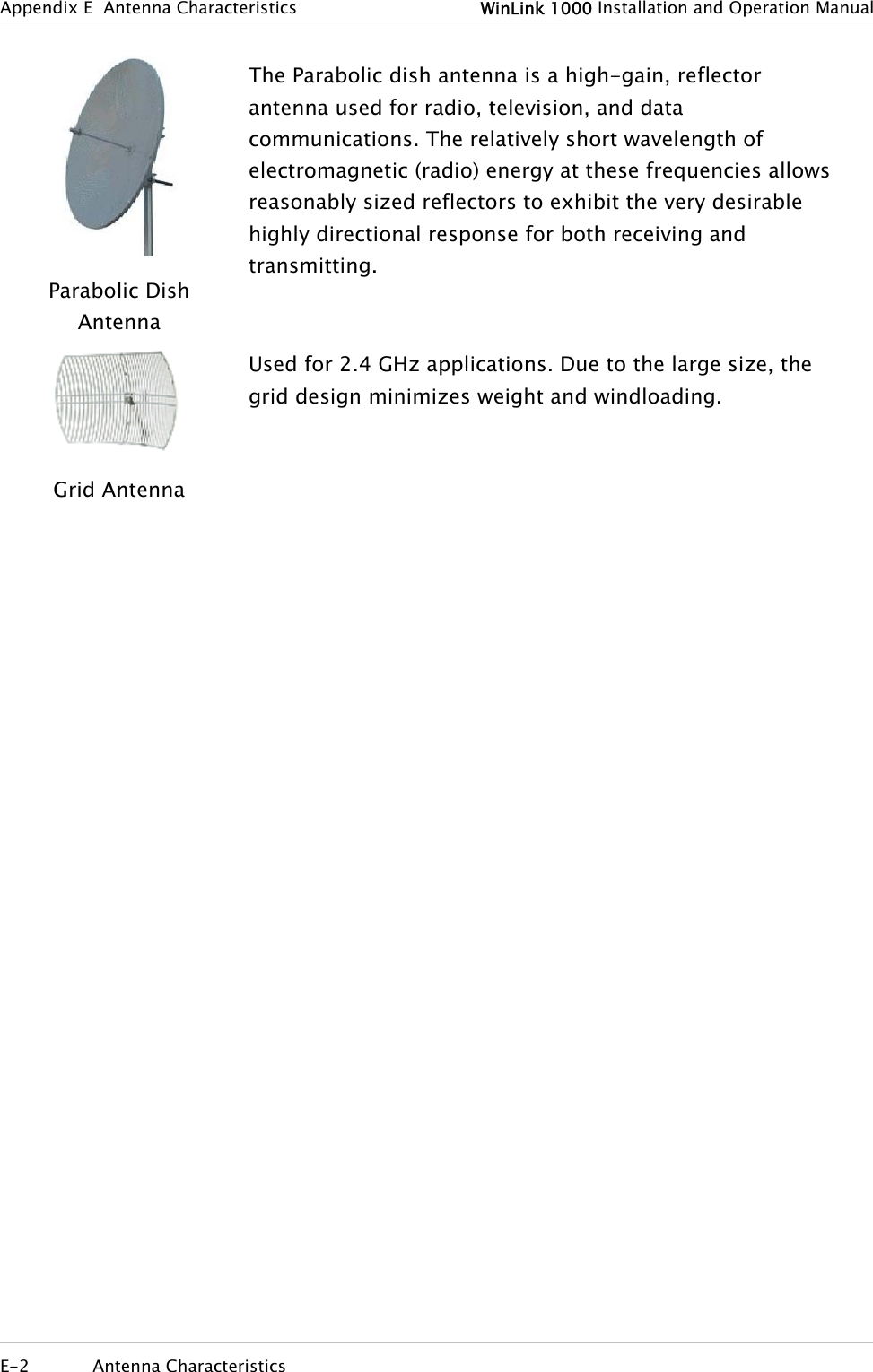
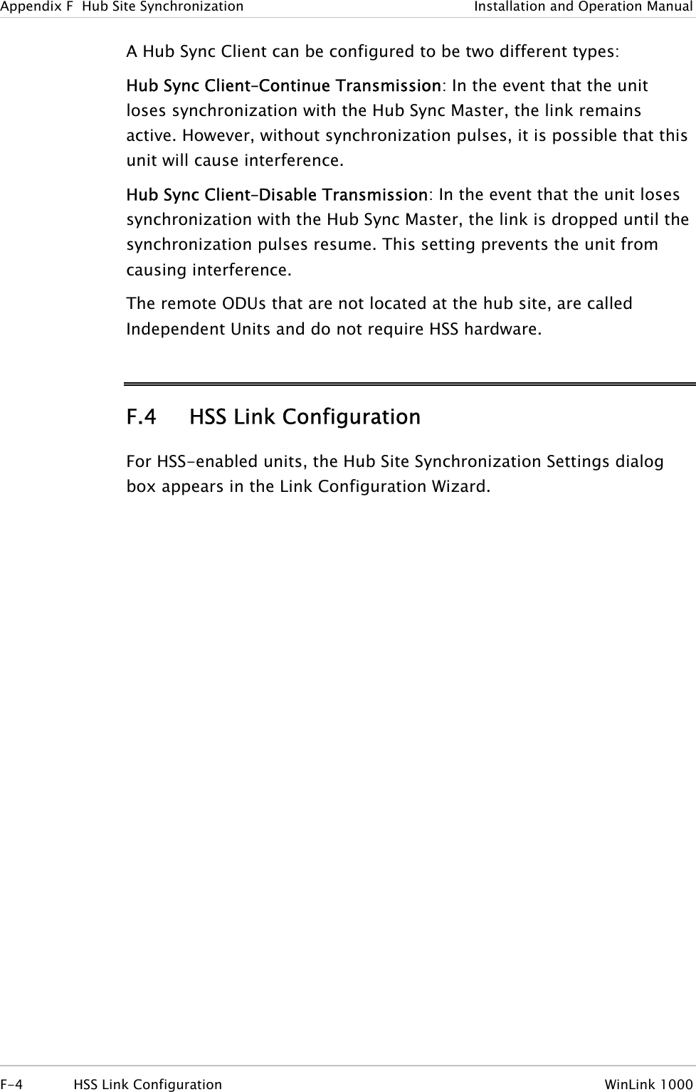
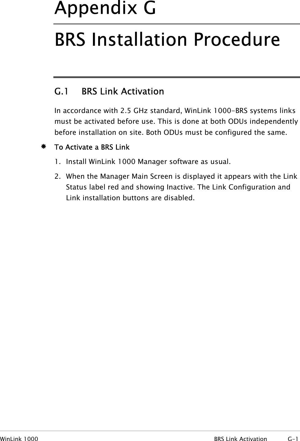
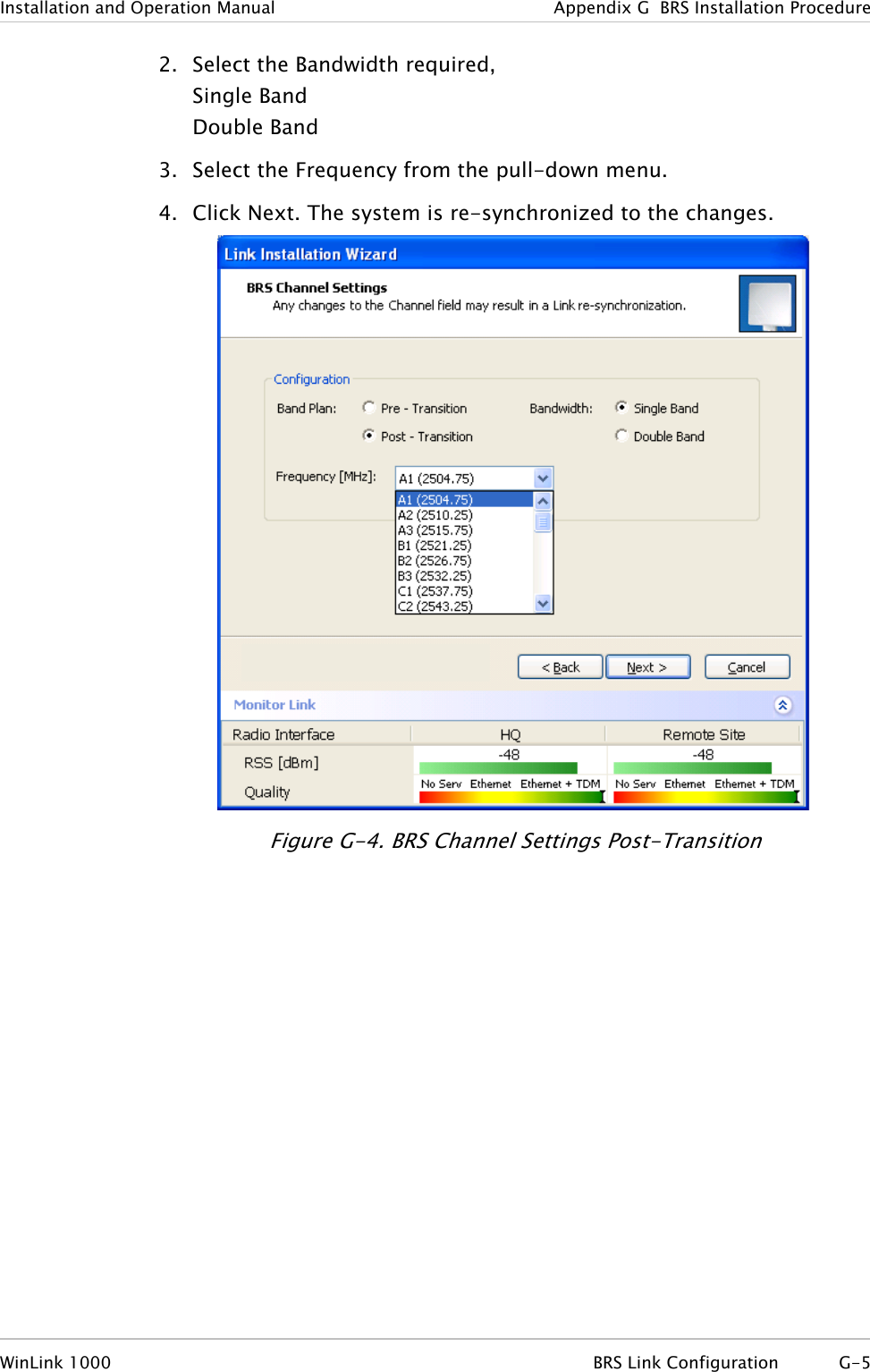
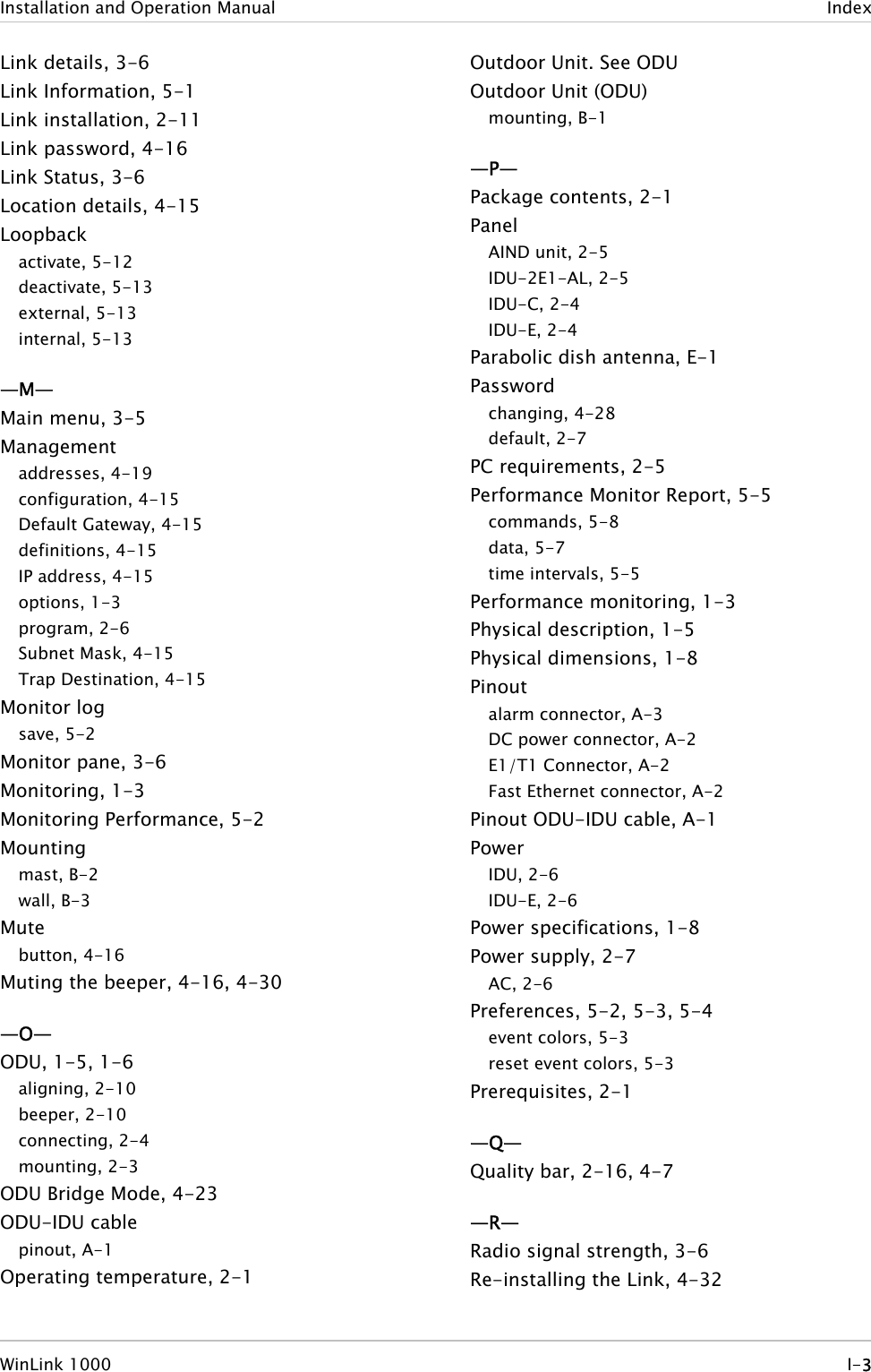
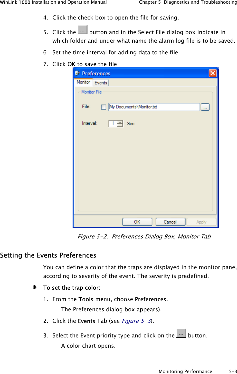
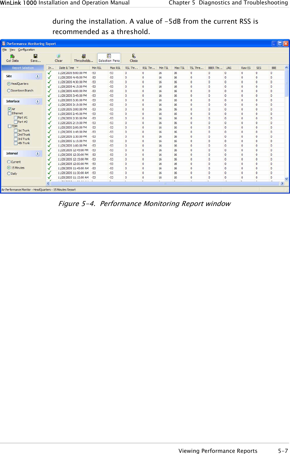
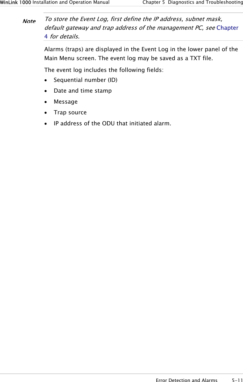
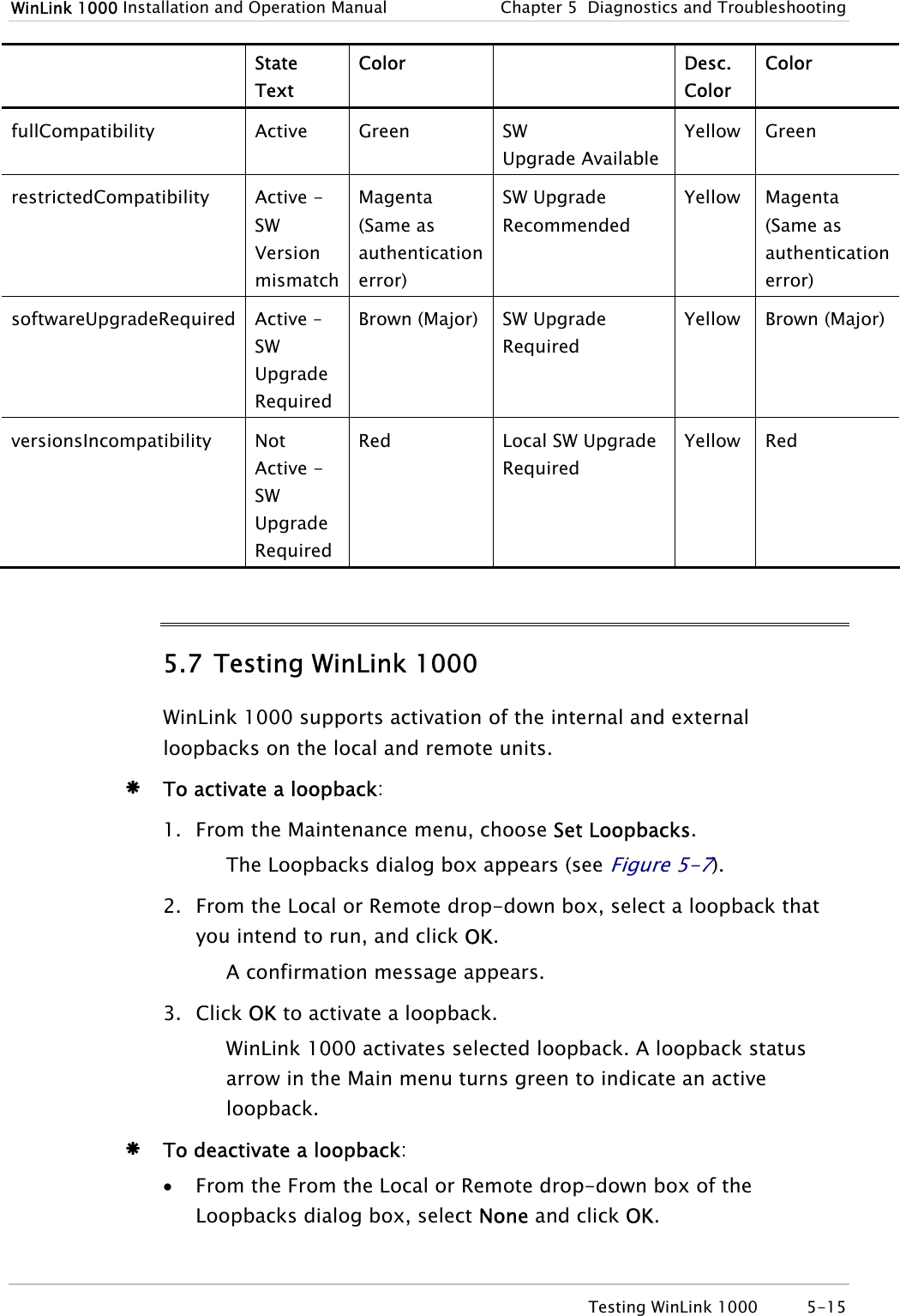
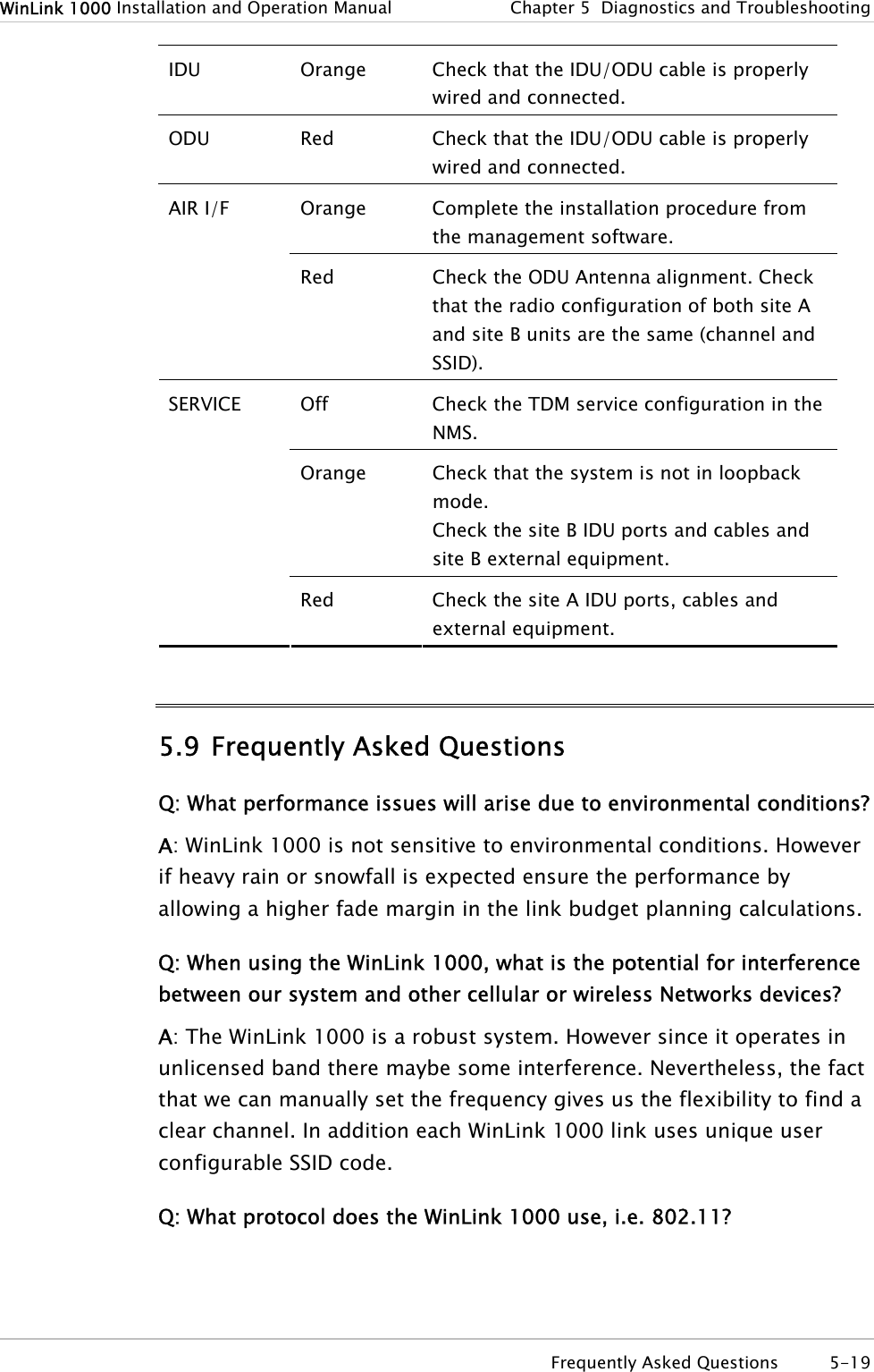
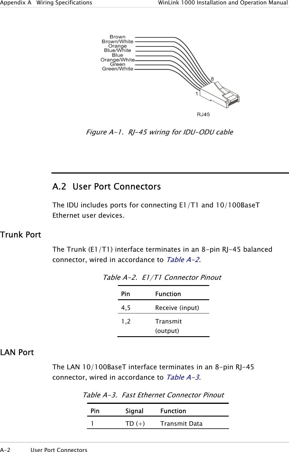
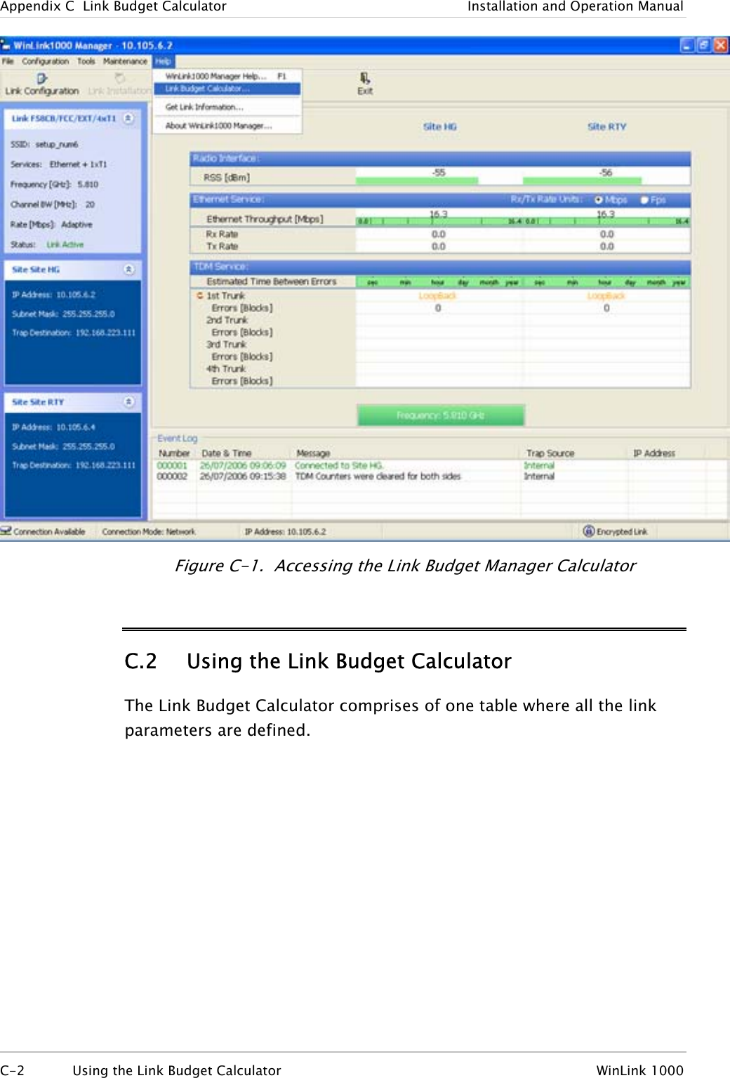
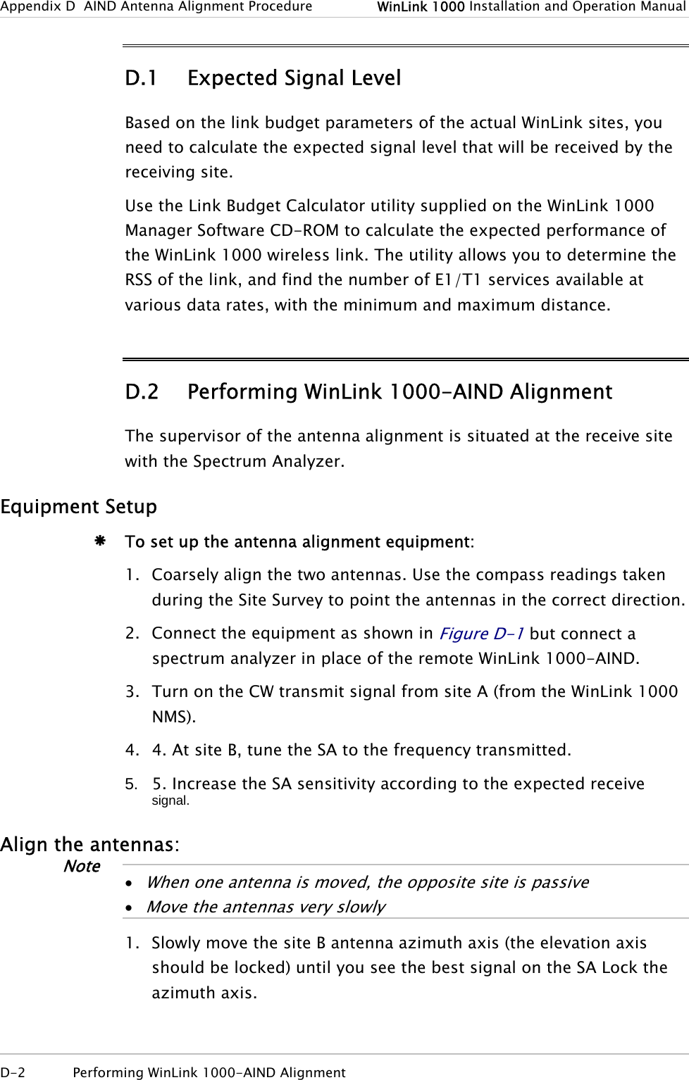
![Appendix H RF Exposure The antennas use for the following transmitters must be installed to provide a separation distance as specified. They must not be co-located or operated in conjunction with any other antenna or transmitter. Product FCC ID Antenna gain [dBi] Min. Safety Distance [cm] F58A/HE/FCC Q3KAMWL1580 22 109 F58A/HE/FCC Q3KAMWL1580 28 217 F58A/HE/FCC F58A/FCC/AIND Q3KAMWL1580 32.5 364 F24A/FCC Q3KAMWL1240 16 16 F24A/FCC Q3KAMWL1240 24 40 F24A/HE/FCC Q3KAMWL1240H 24 71 F24A/HE/FCC Q3KAMWL1240H 15.2 37 WinLink 1000 H-1](https://usermanual.wiki/Radwin/AMWL1240H.Users-Manual-Part-2/User-Guide-800484-Page-56.png)