Redline Communications SC1000E RedMax 4C Remote Radio Headend User Manual 70 00100 01 00 DRAFT
Redline Communications Inc. RedMax 4C Remote Radio Headend 70 00100 01 00 DRAFT
UserManual.wiki
>
Redline Communications
>
SC1000E User Manual
User Manual
Navigation menu
Upload a User Manual
Namespaces
Wiki Guide
HTML
PDF
Info
Views
User Manual
Discussion / Help
Navigation
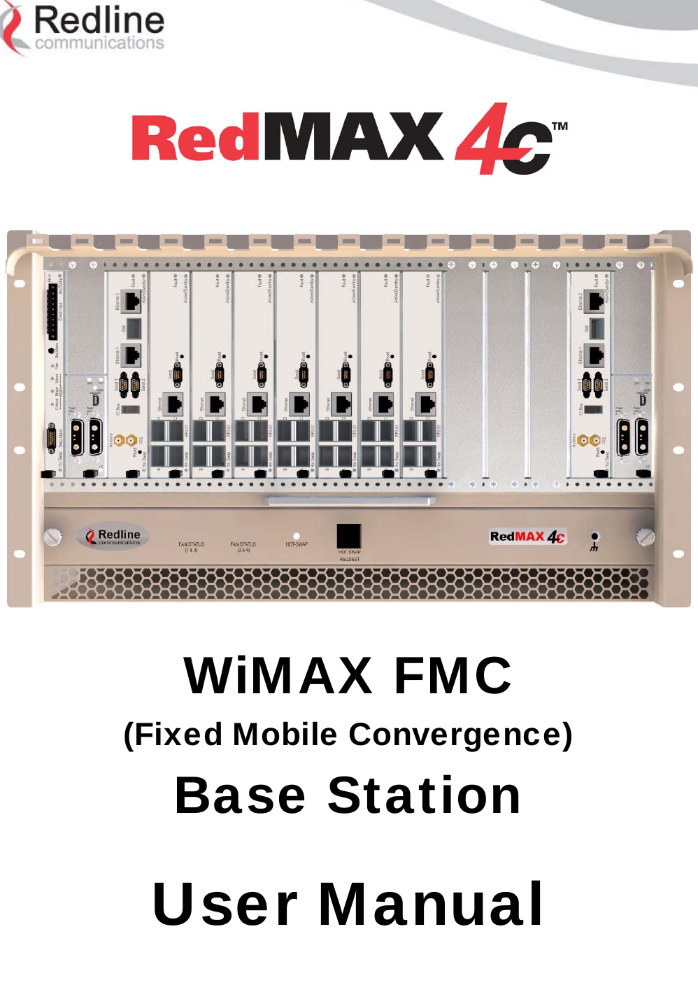
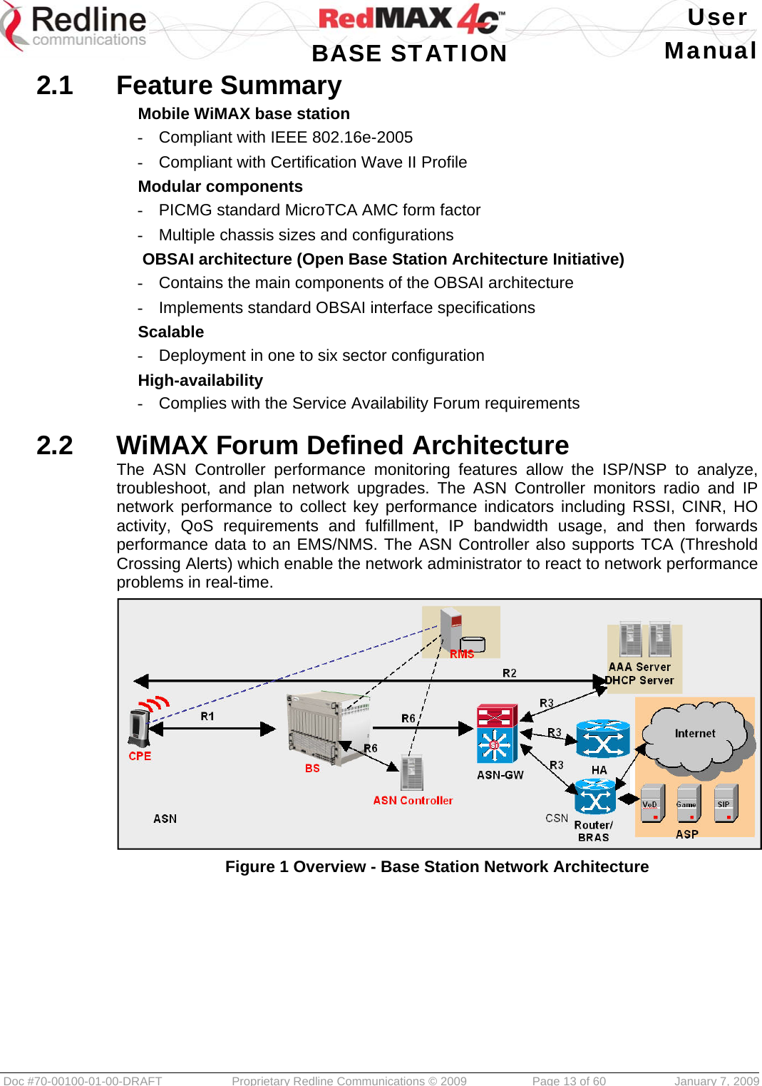
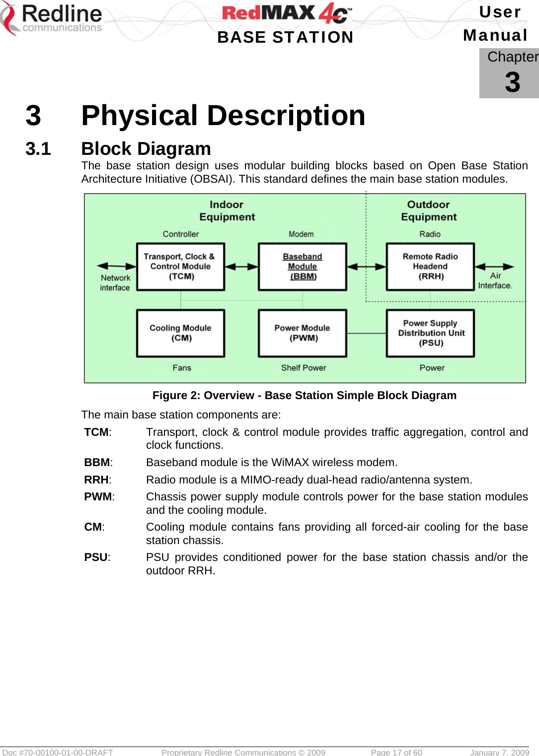
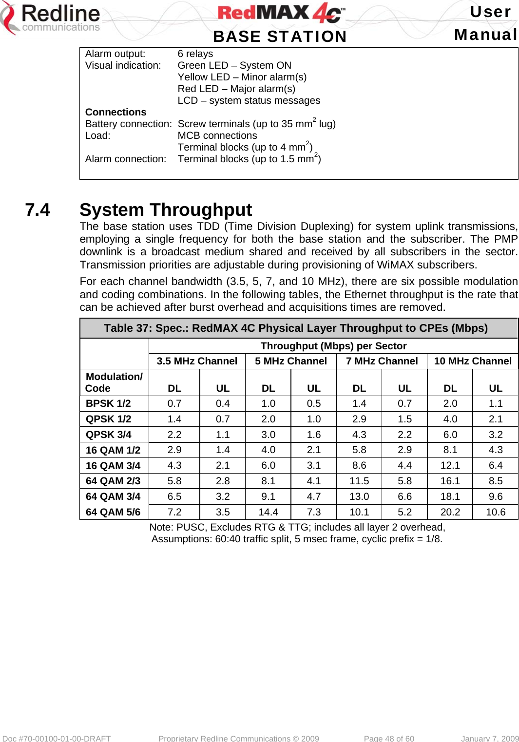
![User BASE STATION Manual Doc #70-00100-01-00-DRAFT Proprietary Redline Communications © 2009 Page 20 of 60 January 7, 2009 3.3.2 Front Panel Interface The following ports and controls are provided: Table 4: Phy - PWM: Front Panel Interface Label Type Description [Handle] SPST Hot-Swap request handle Completely inserted – the module is mechanically locked and is requesting activation Extracted half way – the module is mechanically locked and is requesting deactivation Completely extracted – the module is mechanically unlocked and can be removed when the blue led is solid on Diagnostic USB The port is used only for factory diagnostics. Power I/P A / B D-Sub 7W2 Dual input MicroTCA standard module accepts -48 VDC (nominal battery range) from two independent sources. Table 5: Phy - PWM: Power Input Pinout (A & B) Pin Description A2 - Ve 1 Connected to pin 2 2 Connected to pin 1 3 Not Used 4 Not Used 5 Not Used A1 + Ve 3.3.3 LED Indicators The PWM module has the following front panel LED indicators: Table 6: Phy - PWM: Power Module LED Indicators LED Color Description OOS Red Out of Service Indicator Solid On - one or more input or output voltages are below normal level or the module temperature is exceeding critical threshold Solid Off – the module is functional. RDY Green Power Supply Ready Indicator Solid On – the module is operational and selected as active (for redundant configurations) Long Blink – the module is operational and designated as standby for redundancy Fast Blink – the module is operational only for TCM and CM power channels Solid Off – the module is not operational HSMA Amber Hardware System Management Activity (HSMA) Blink - indicates that the PWM is communicating with the TCM](https://usermanual.wiki/Redline-Communications/SC1000E/User-Guide-1062245-Page-20.png)
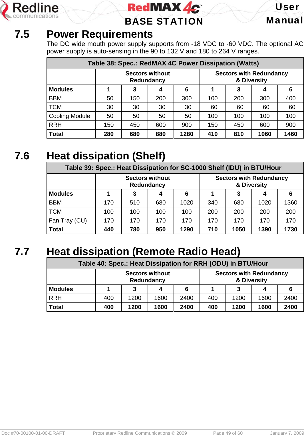
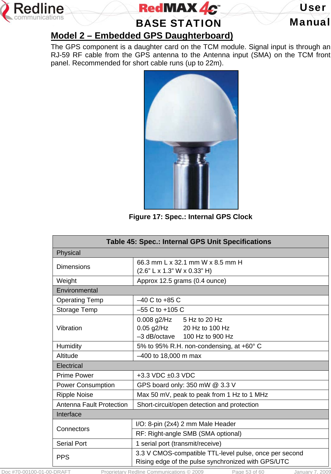
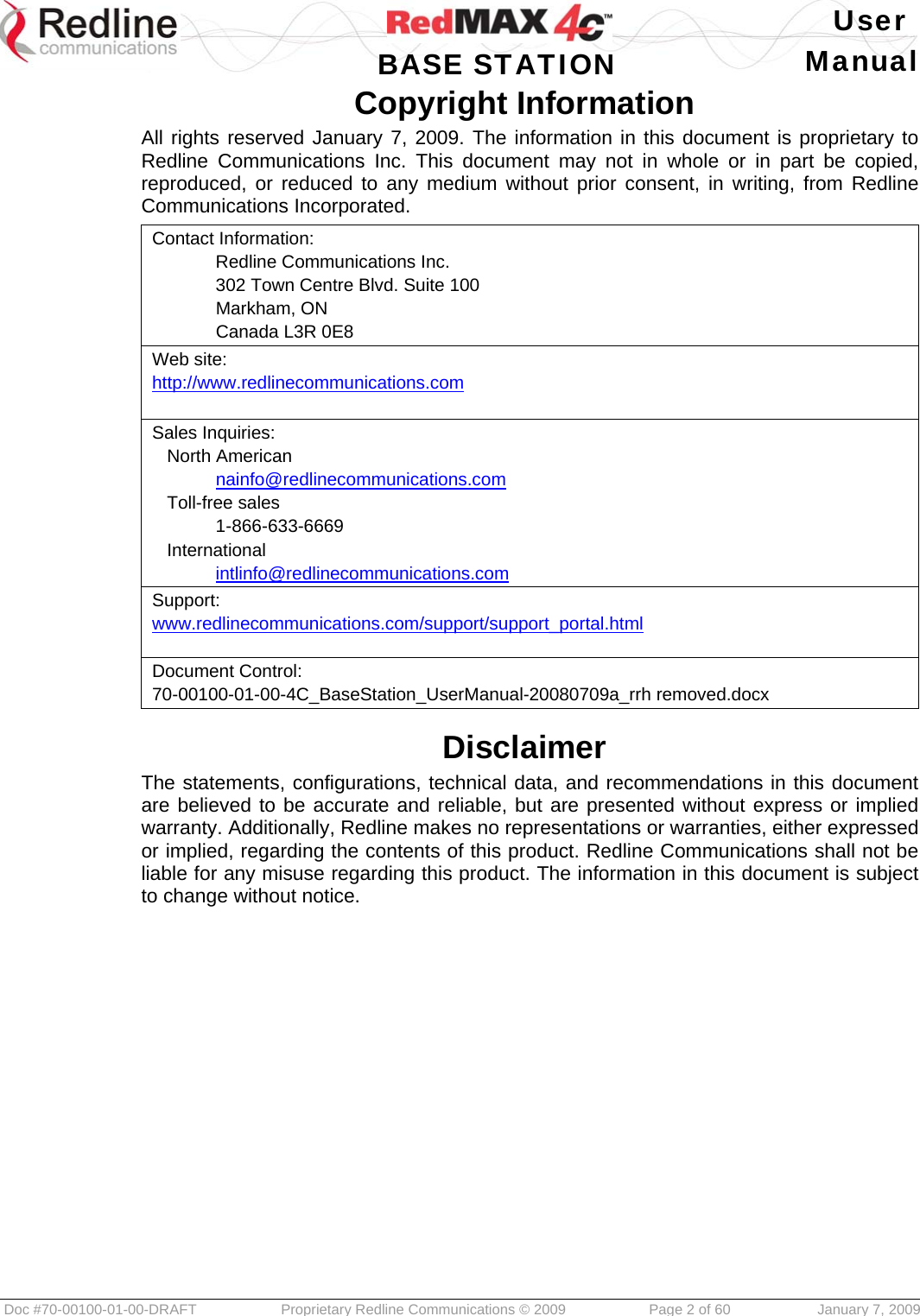
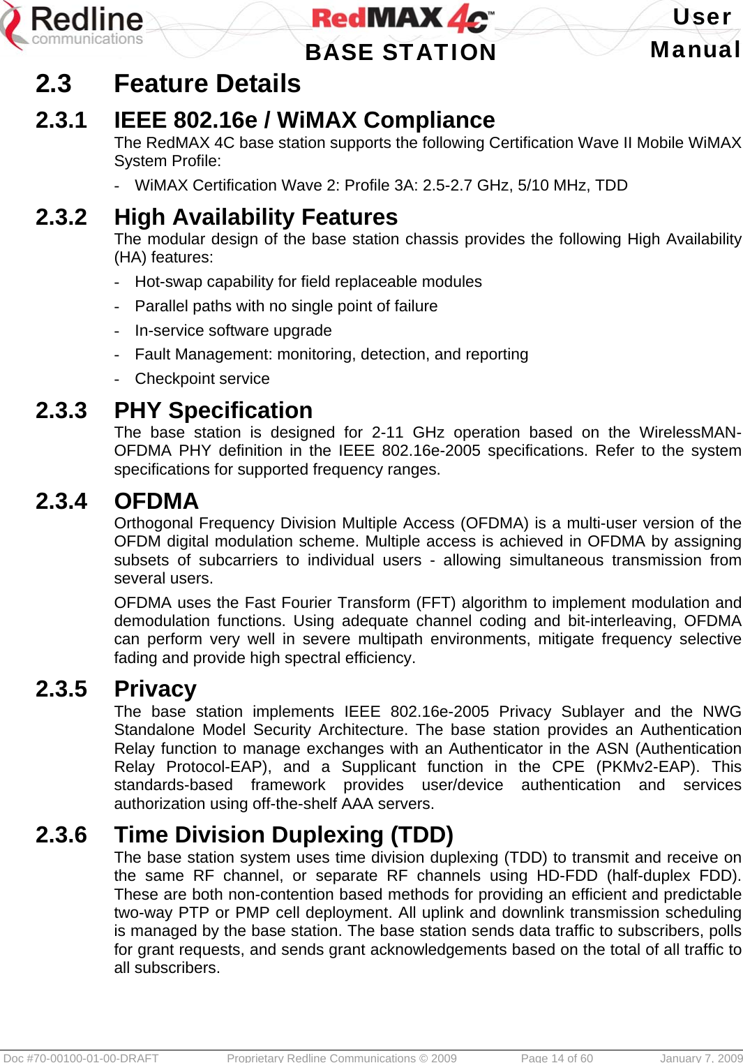
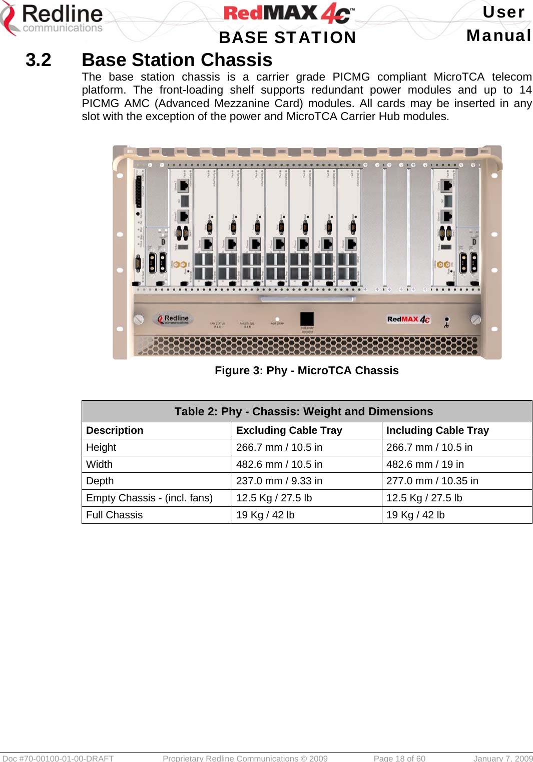
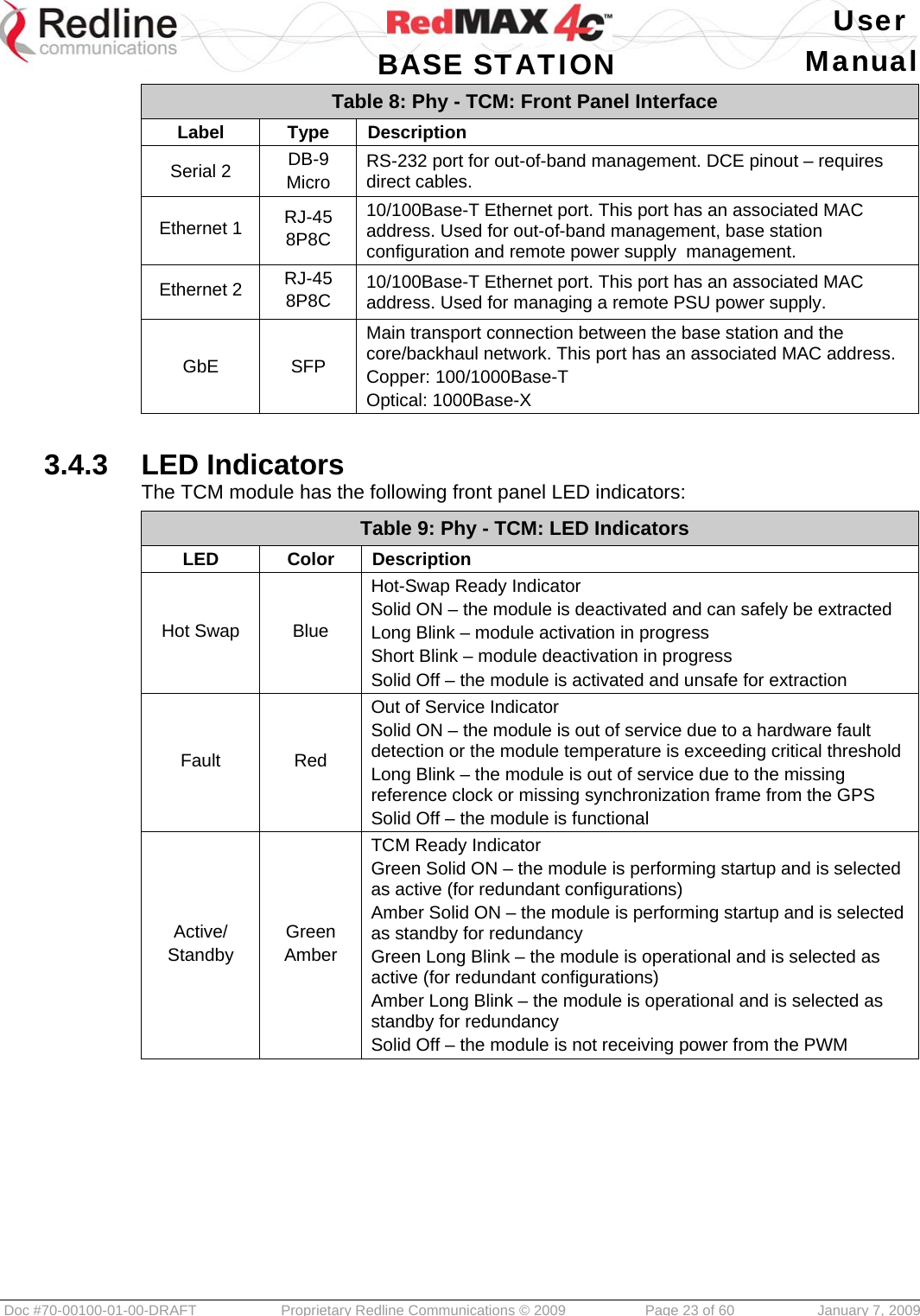
![User BASE STATION Manual Doc #70-00100-01-00-DRAFT Proprietary Redline Communications © 2009 Page 22 of 60 January 7, 2009 3.4 TCM - Transport, Clock & Control Module The Transport, Clock & Control Module (TCM) is a multi-purpose card combining the OBSAI Transport Block and Control & Clock Block functions. 3.4.1 Module Description The transport function manages traffic aggregation and the control and clock functions provide synchronization between the base station modules. Downstream data traffic received from the core network is distributed to the baseband modules for transmission over the wireless network, while upstream traffic from the wireless system is aggregated and sent over the backhaul connection to the core network. The base station clock is synchronized by a GPS reference signal. Clock signals are sent through the backplane to the other base station modules. The shelf may contain up to two TCM modules for redundancy. The TCM module is fully 'hot swappable' and the standby unit may be removed and installed without affecting operation of the base station (refer to 'Using the Hot-Swap Feature' in the installation guidelines). The following TCM models are available: Table 7: Phy - TCM: Controller Module Types TCM 1000 The TCM 1000 is the first generation base station controller module. Figure 5: Phy - TCM: MicroTCA Controller Hub Front Panel Interface 3.4.2 Module Description The following ports and controls are provided: Table 8: Phy - TCM: Front Panel Interface Label Type Description [Handle] SPST Hot-Swap request handle Inserted completely – the module is mechanically locked and is requesting activation Extracted half way – the module is mechanically locked and is requesting deactivation Extracted completely – the module is mechanically unlocked and can be removed when the blue led is solid on Reset Push-to-Make Press this switch to reboot the module. Antenna SMA GPS antenna input for Trimble Bullet III or equivalent antenna. PPS SMA External 1 PPS GPS clock signal (LvTTL pulse). Currently not supported by the module. I2C Bus USB Factory diagnostics only. Do not connect USB devices ! Serial 1 DB-9 Micro RS-232 port accepts a standard GPS 1 PPS synchronization signal. DTE pinout - requires cross over cables.](https://usermanual.wiki/Redline-Communications/SC1000E/User-Guide-1062245-Page-22.png)
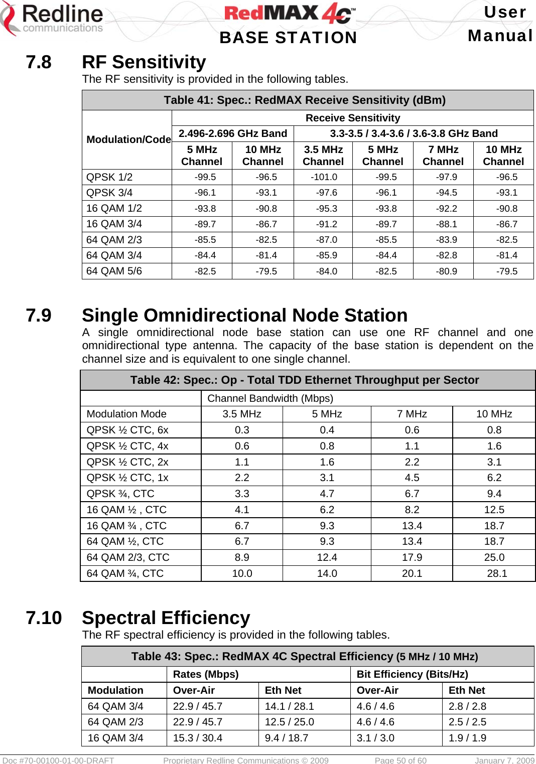
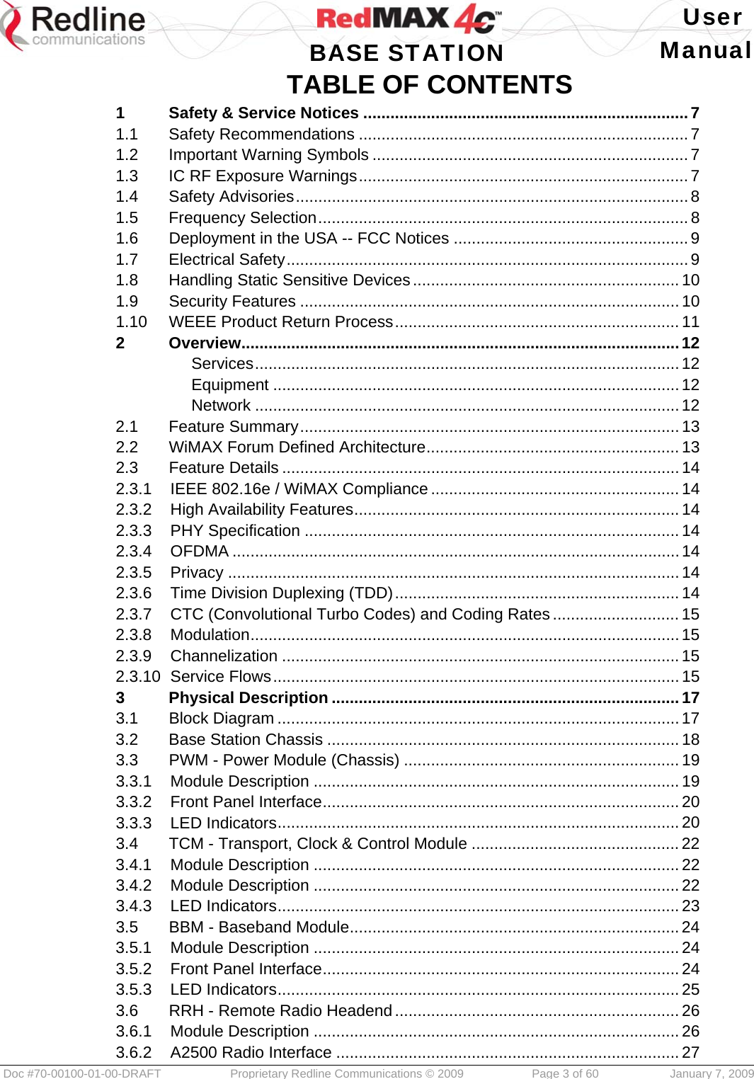
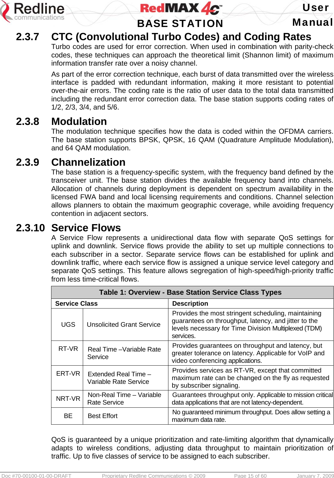
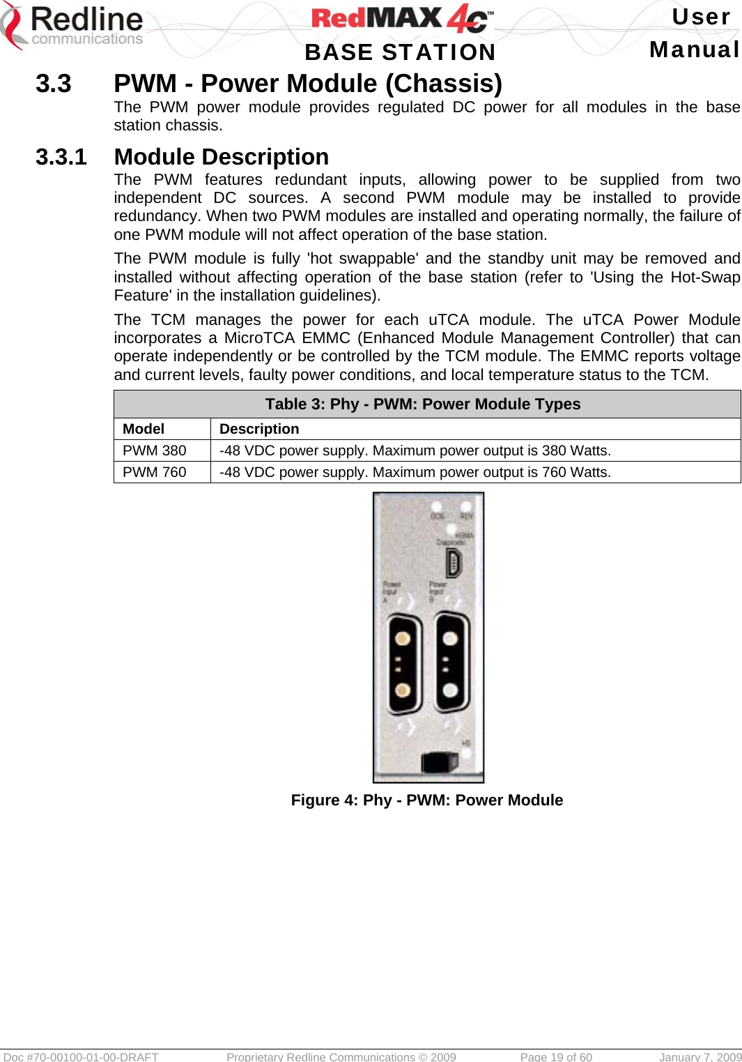
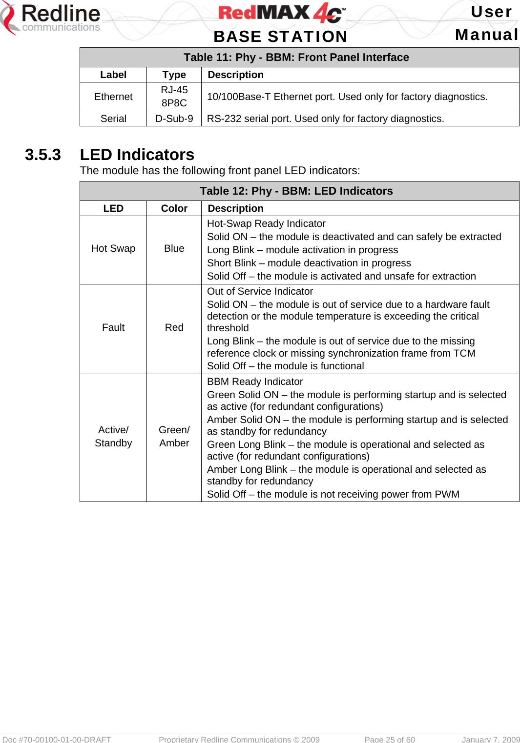
![User BASE STATION Manual Doc #70-00100-01-00-DRAFT Proprietary Redline Communications © 2009 Page 24 of 60 January 7, 2009 3.5 BBM - Baseband Module The baseband module (BBM) is a WiMAX wireless modem (IEEE 802.16e PHY and MAC). 3.5.1 Module Description Downstream data traffic received from the core network is distributed to the baseband modules for transmission over the wireless network, while upstream traffic from the wireless system is aggregated and sent over the backhaul connection to the core network. This port has an associated MAC address. Each BBM connects to one RRH (one sector) and supports two SISO channels or one MIMO channel. Up to six BBM (plus two standby) modules may operate concurrently. The BBM is frequency agnostic (frequency band determined by RRH). The base station shelf supports an N+1 redundancy configuration. The OBSAI RP3-01 interface cabling must be provided from each standby BBM module to a radio. The BBM module is fully 'hot swappable' and may be removed and installed without powering off the chassis. Removing and replacing a BBM module will not affect operation of the base station. Table 10: Phy - BBM: Module Types BBM 1000 SISO-based baseband module. BBM 2000 MIMO-based baseband module. Figure 6: Phy - BBM: Baseband Module (BBM2000) 3.5.2 Front Panel Interface The following ports and controls are provided: Table 11: Phy - BBM: Front Panel Interface Label Type Description [Handle] SPST Hot-Swap request handle Inserted completely – the module is mechanically locked and is requesting activation Extracted half way – the module is mechanically locked and is requesting deactivation Extracted completely – the module is mechanically unlocked and can be removed when the blue led is solid on A, B, C, D SFP Connection from the base station RRH. Optical: 1000Base-X, 100/1000Base-T 50/125 UM Fiber Optic, Type OFNR, -40°C to +75°C Outdoor Rated – 7 mm (0.28 in) OD. X 91 m (300 ft) max. length Max. allowable cable signal loss: 8 dB Reset Push-to-Make Press this switch to reboot the module.](https://usermanual.wiki/Redline-Communications/SC1000E/User-Guide-1062245-Page-24.png)
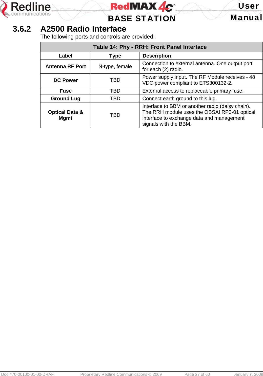
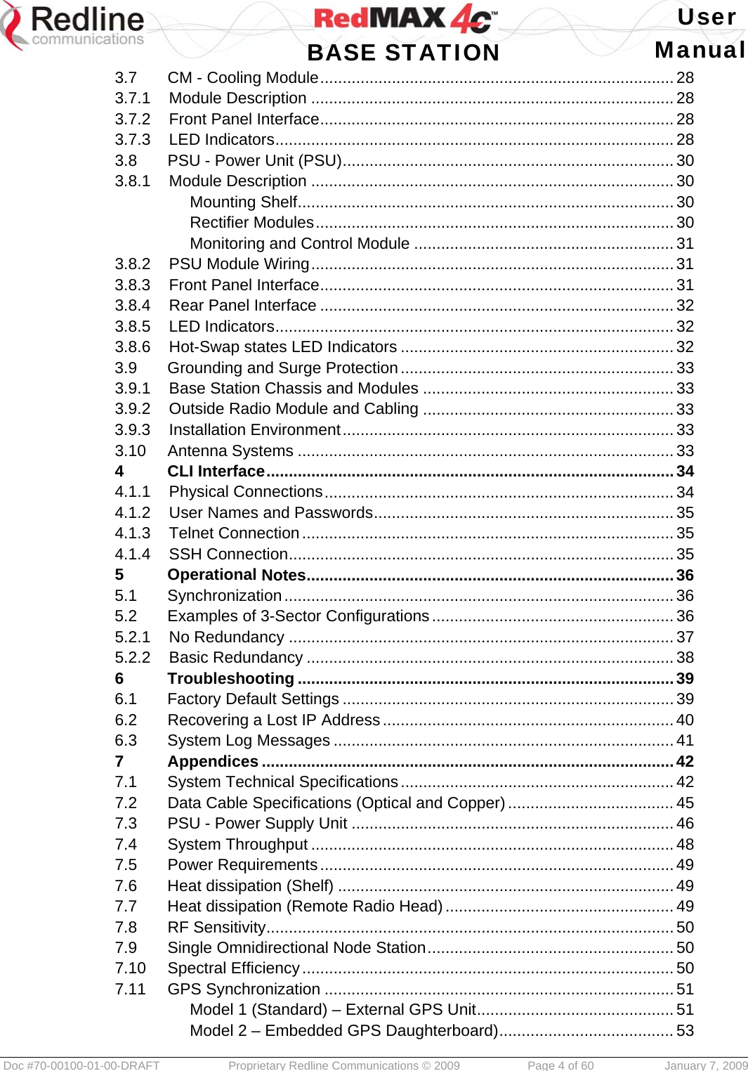
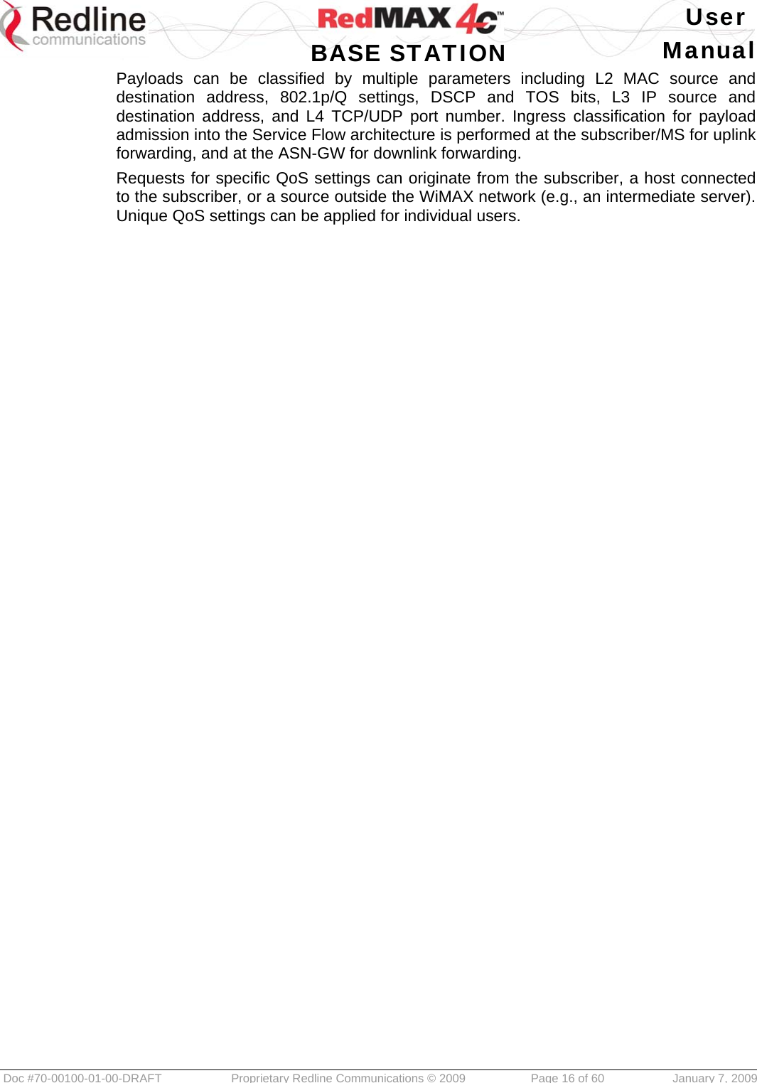
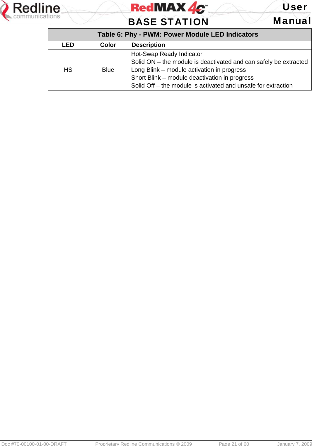
![User BASE STATION Manual Doc #70-00100-01-00-DRAFT Proprietary Redline Communications © 2009 Page 31 of 60 January 7, 2009 Monitoring and Control Module All rectifier input and output voltages are supervised locally by the Power Monitor and Control Module. The base station supervises the PSU remotely using an Ethernet connection to the module. Figure 11: Phy - PSU: Power Monitor and Control Module 3.8.2 PSU Module Wiring All PSU wiring connections are located inside the PSU chassis. The PSU features a front pull-out shelf providing access to all terminal blocks. Power input cables should have the following minimum ratings: 16 AWG/2 conductors, copper stranded, shielded, -40 C to 90 C, 8 mm (0.31 in) O.D. 3.8.3 Front Panel Interface The following ports and controls are provided: Table 17: Phy - PSU: Front Panel Interface Label Type Description [none] LCD Display Display system status messages. USB USB The USB port is used only for factory diagnostics. Push-to-make Up button to control the LCD display. Push-to-make Down button to control the LCD display. Push-to-make Enter button to control the LCD display.](https://usermanual.wiki/Redline-Communications/SC1000E/User-Guide-1062245-Page-31.png)
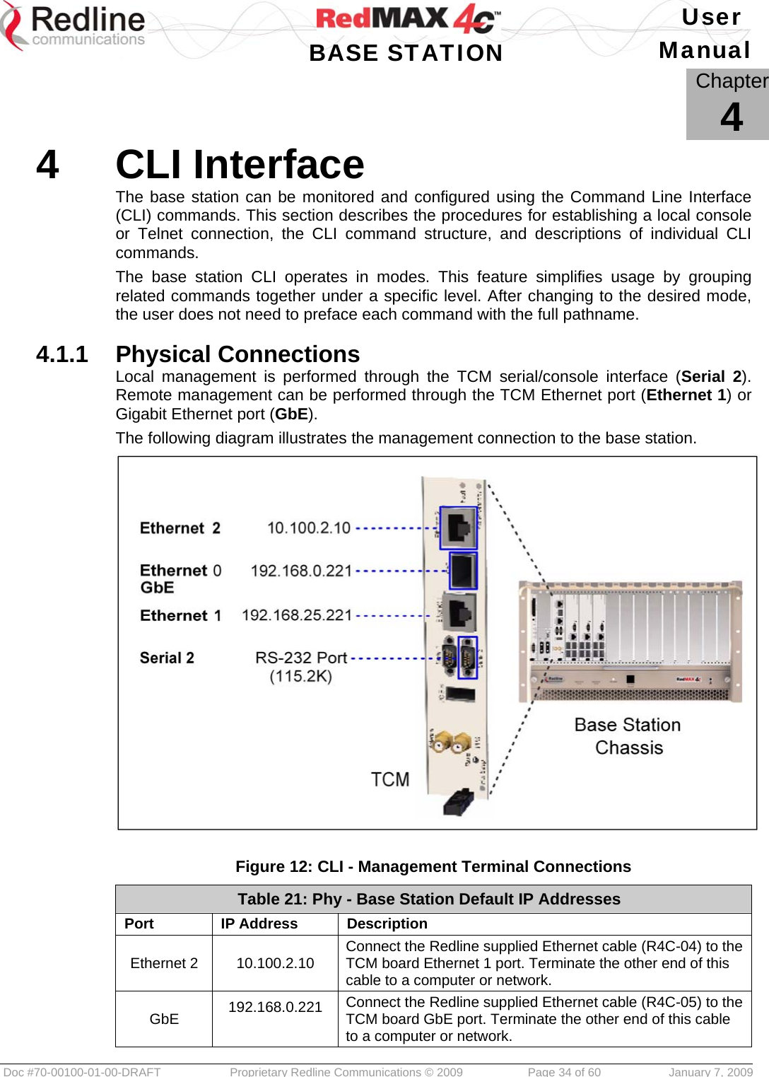
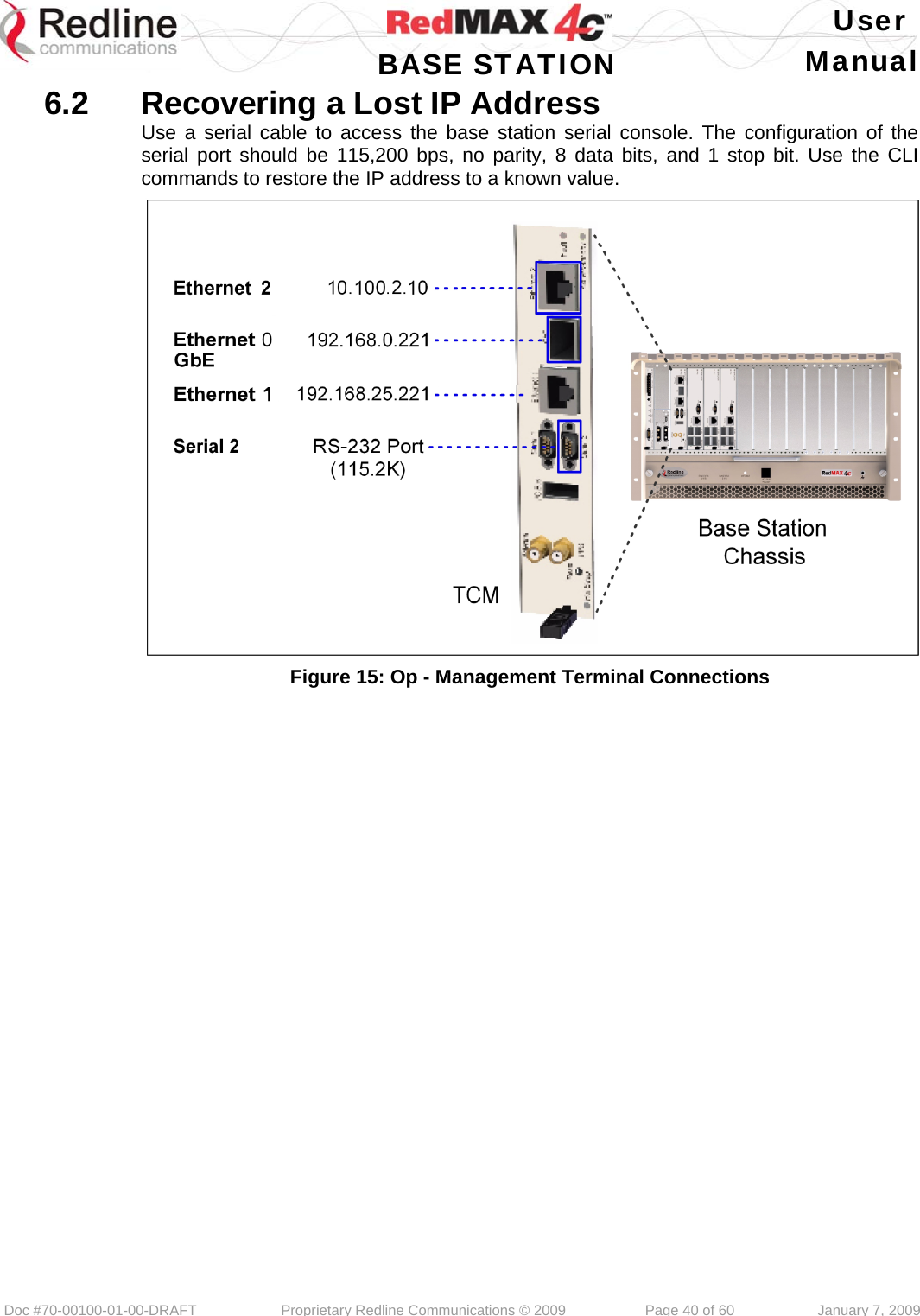
![User BASE STATION Manual Doc #70-00100-01-00-DRAFT Proprietary Redline Communications © 2009 Page 35 of 60 January 7, 2009 Table 21: Phy - Base Station Default IP Addresses Ethernet 1 192.168.25.221 Out-of-band management Serial 2 N/A Connect the Redline supplied serial console cable (R4C-03) to the TCM board Serial 2 port. If the host does not have a serial connector, use an RS-232-to-USB converter. Settings: Baud rate: 115200; Data bits: 8; Flow Control: None; Parity: None; Stop Bits: 1 4.1.2 User Names and Passwords The base station is shipped from factory with the following default user names and passwords. It is suggested that during commissioning, the system administrator should perform a system audit and assign new user names and passwords to all accounts. Table 22: Phy - Base Station Default Usernames and Passwords Account Username Password Administrator Cli Cli 4.1.3 Telnet Connection Type telnet followed by the IP address for the selected system access port and press ENTER. Enter the account and password when prompted. Example for GbE port: telnet 192.168.25.221 [ENTER] cli [ENTER] cli [ENTER] Result: Copyright (c) 2006-2007 Redline Communications Inc. http://www.redlinecommunications.com SC1000> Telnet Logout: To exit from the telnet session, type quit [ENTER]. 4.1.4 SSH Connection SSH login: To begin an ssh session, type ssh followed by the IP address for the selected system access port and press ENTER. Type the account and password when prompted. Example: ssh cli@192.168.25.221 [ENTER] cli [ENTER] Result: Copyright (c) 2006-2007 Redline Communications Inc. http://www.redlinecommunications.com SC1000> SSH logout: To exit from an ssh session, type exit then press ENTER.](https://usermanual.wiki/Redline-Communications/SC1000E/User-Guide-1062245-Page-35.png)