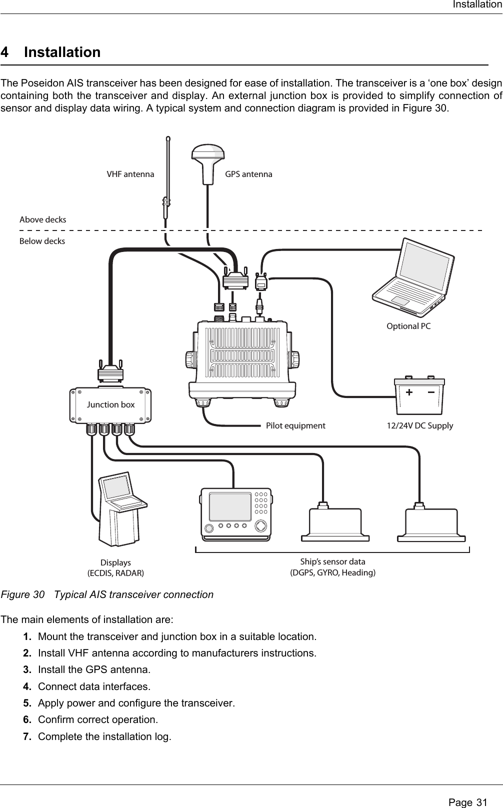
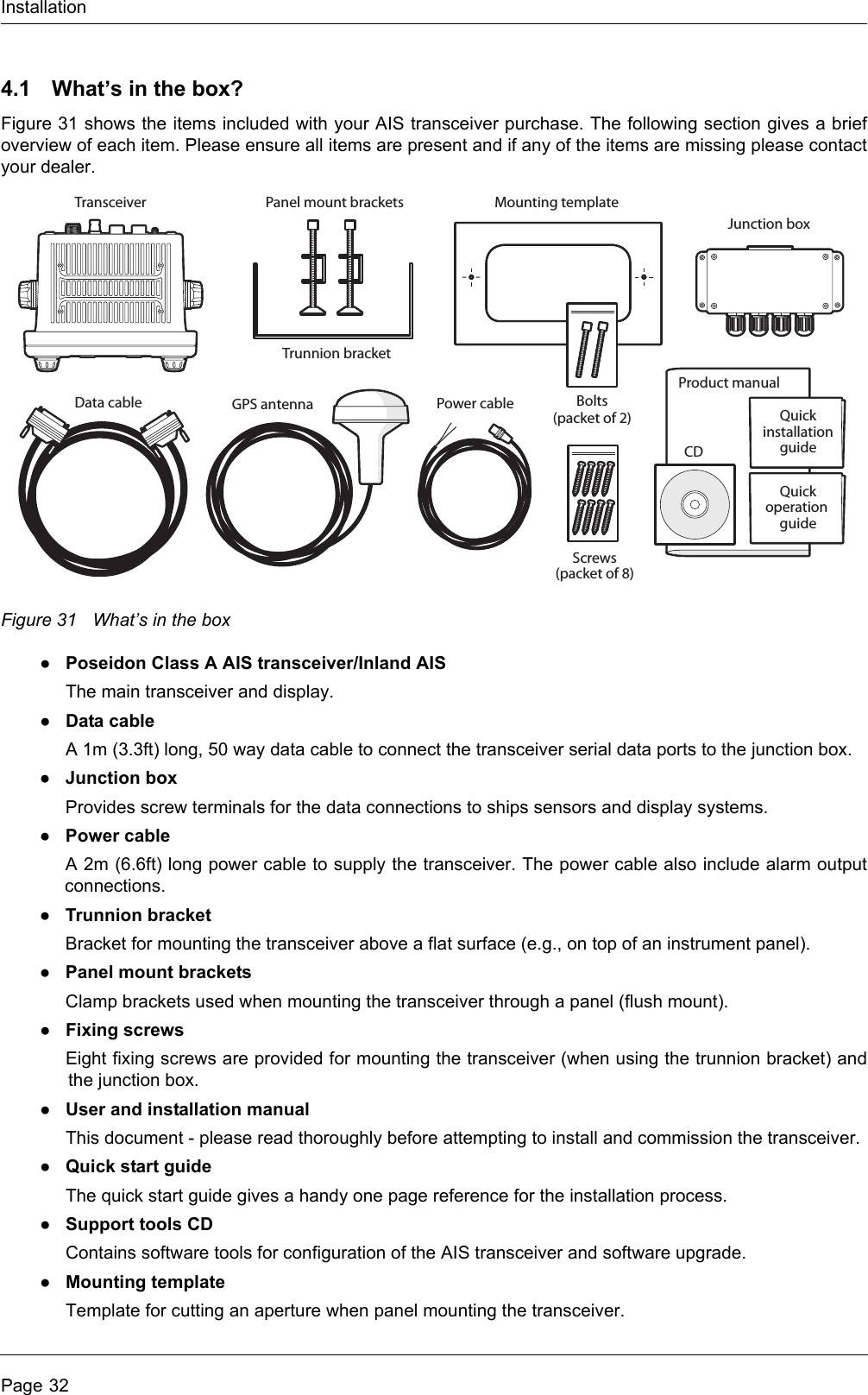
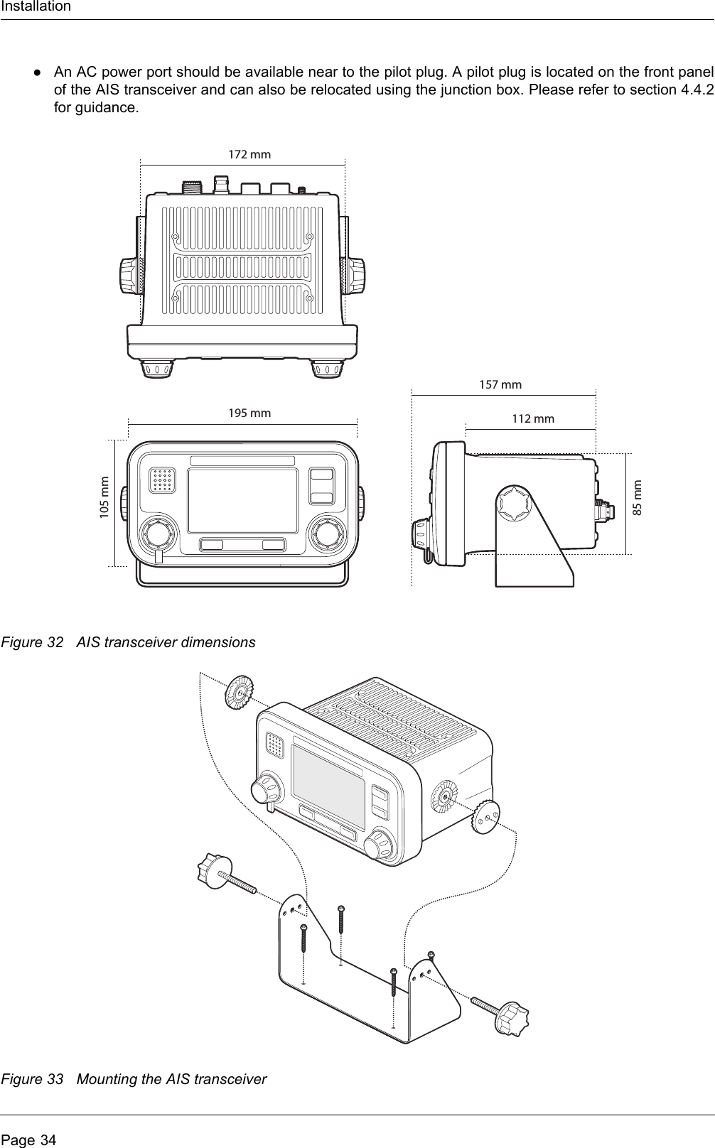
SRT Marine Systems plc 405-0002 Marine Class A AIS Transceiver User Manual Poseidon installation and user guide
Software Radio Technology plc Marine Class A AIS Transceiver Poseidon installation and user guide
Contents
- 1. Installation and users guide
- 2. User manual
Installation and users guide


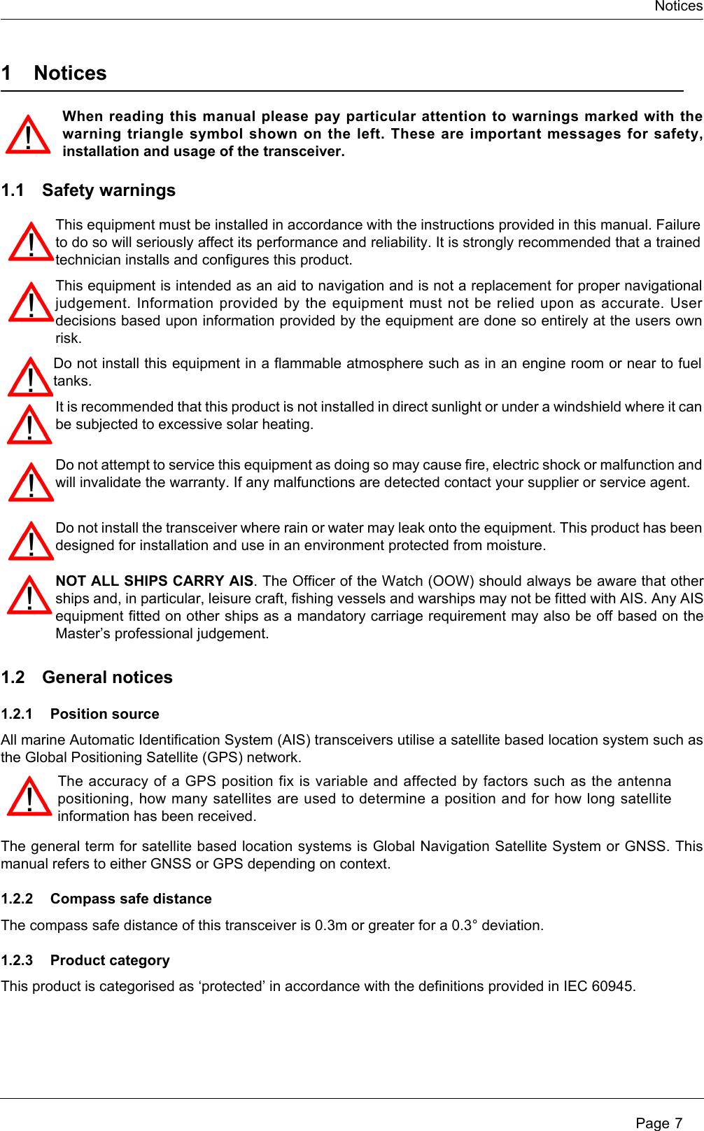
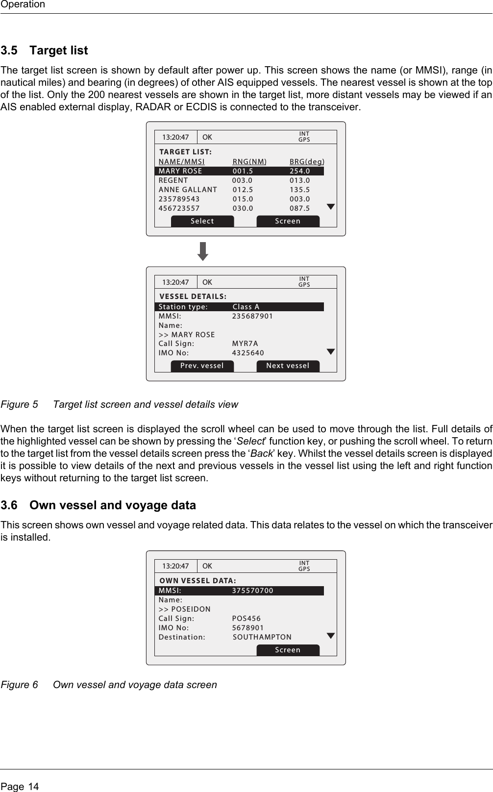
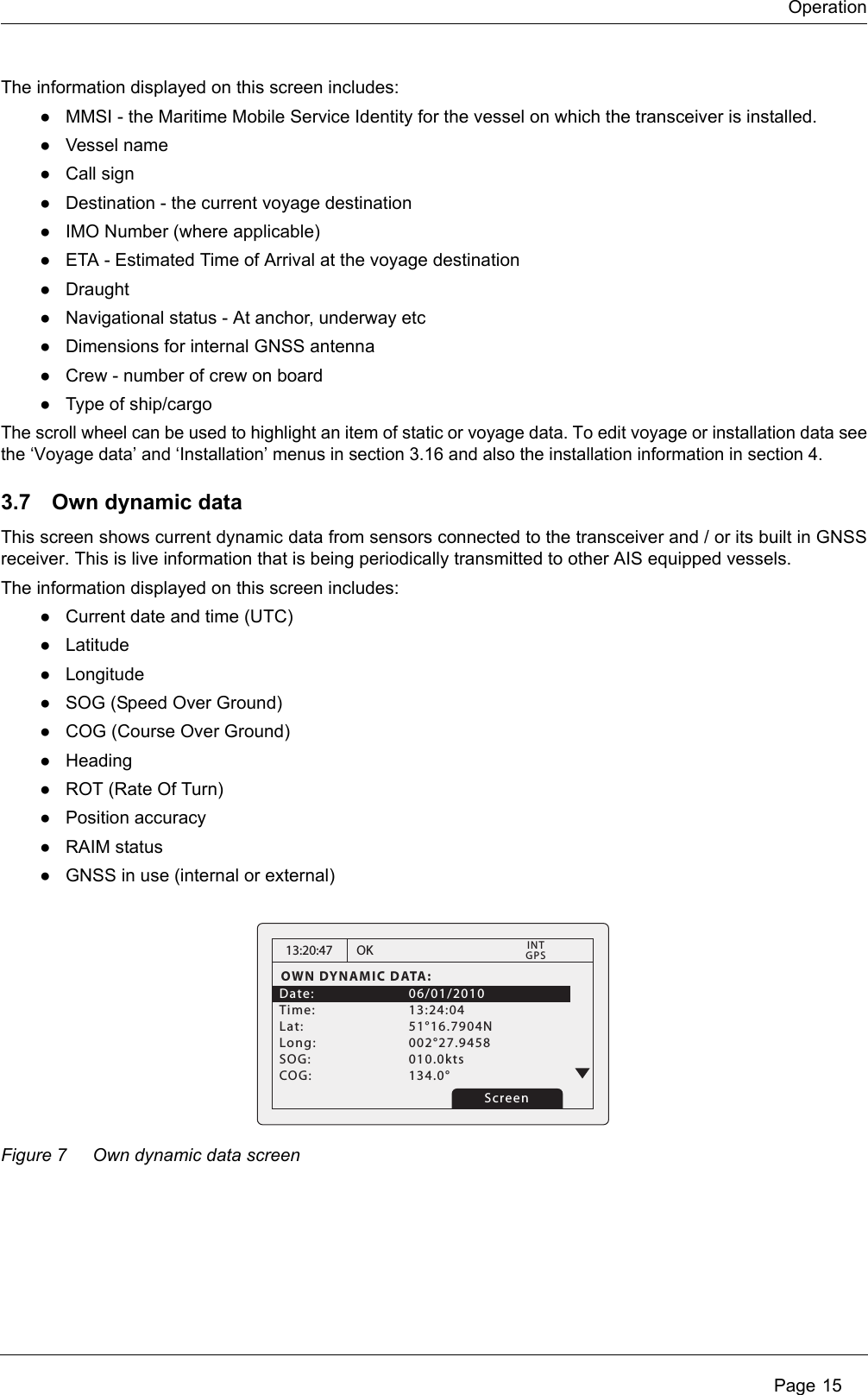
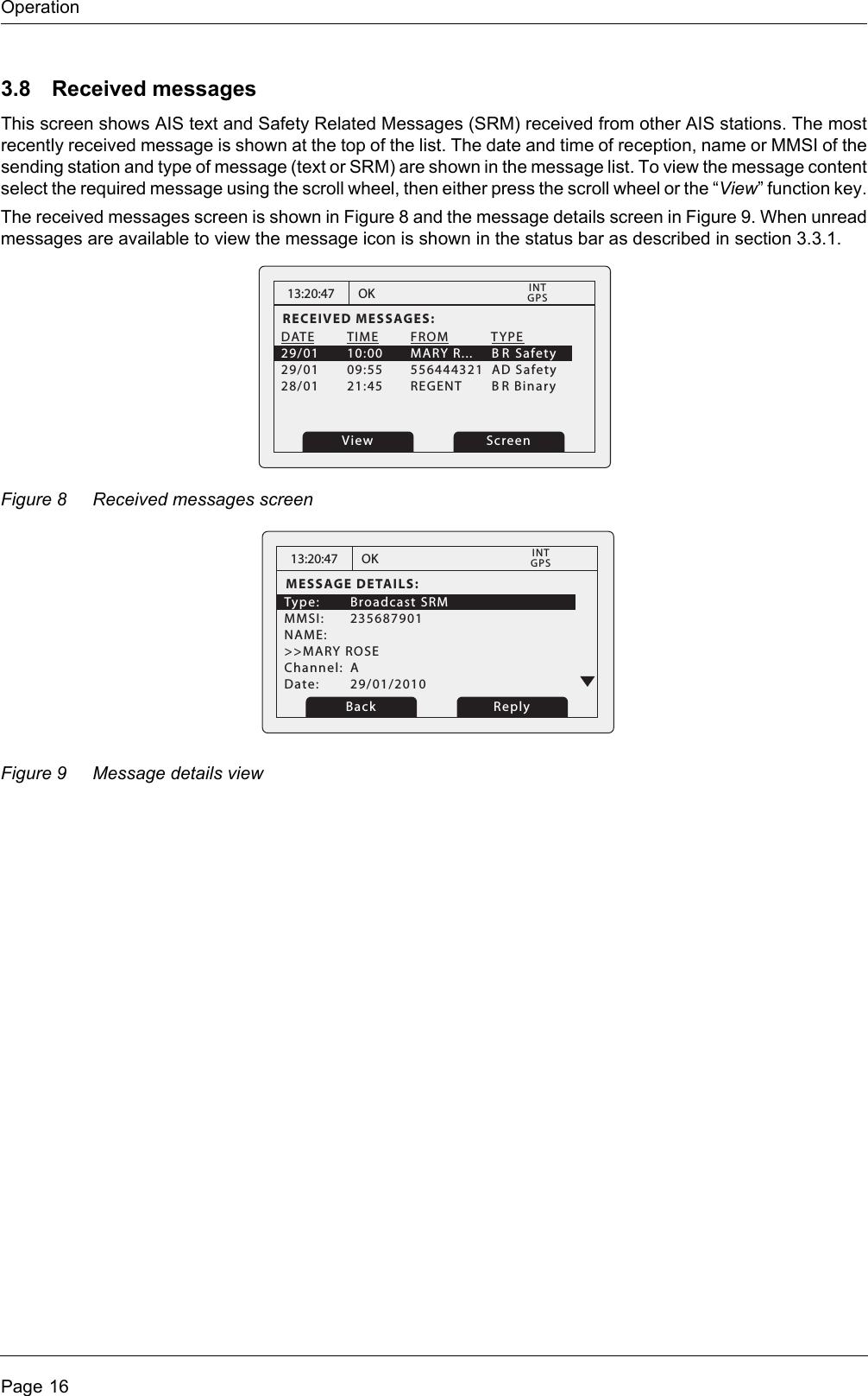
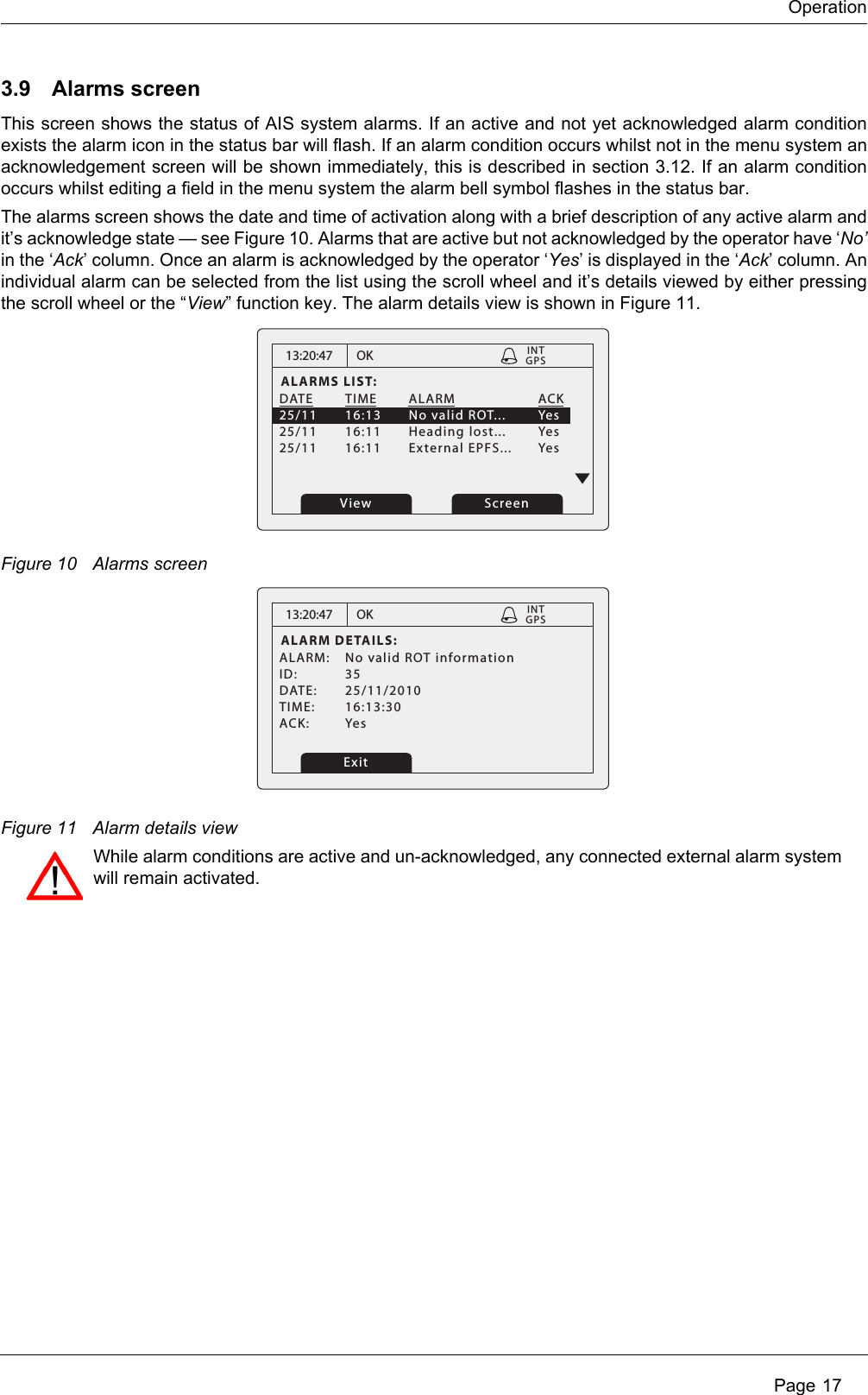
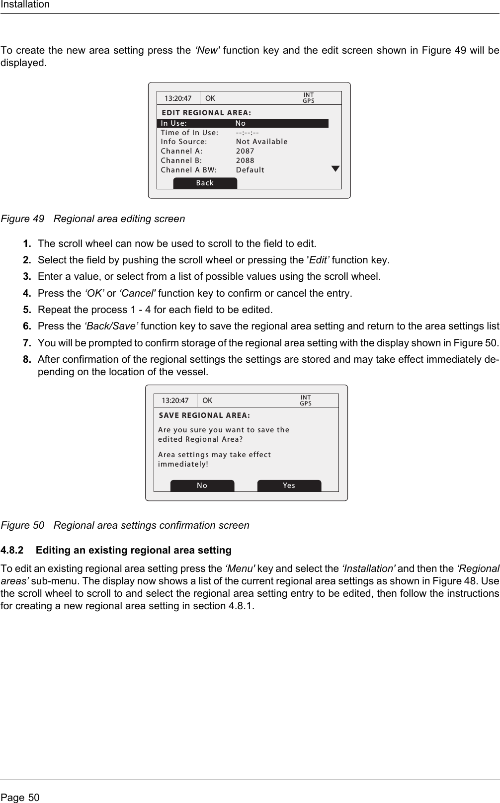
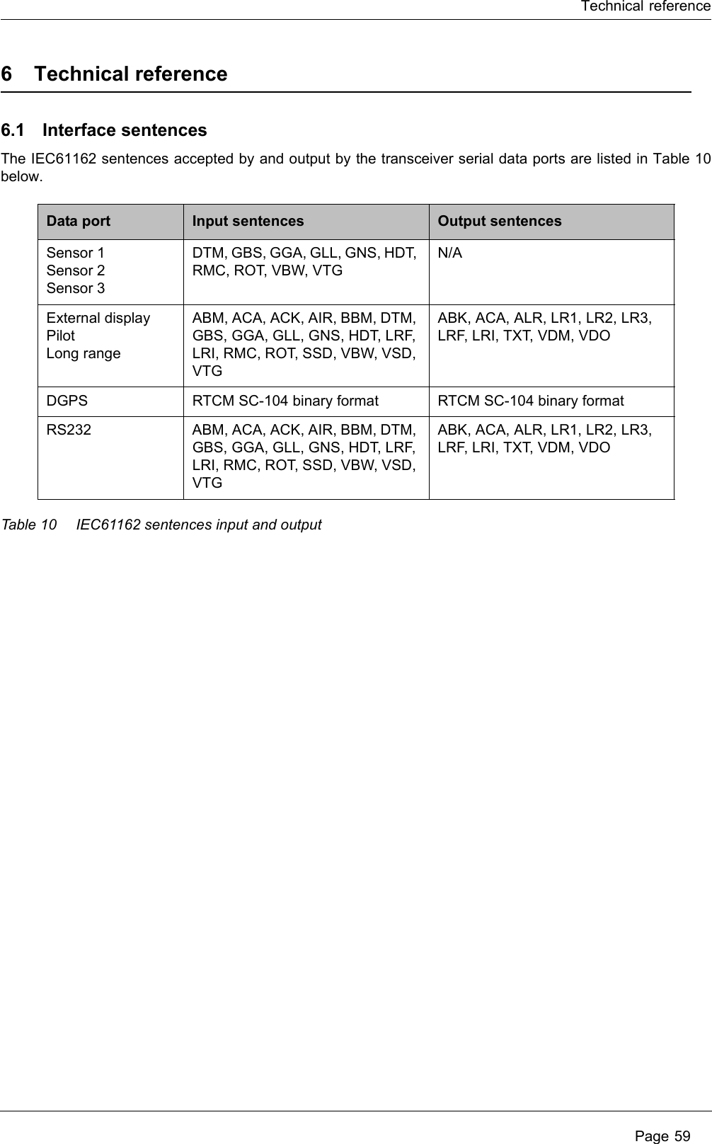
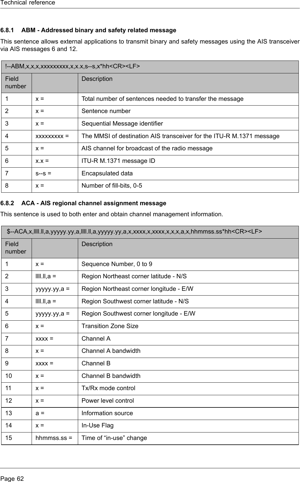
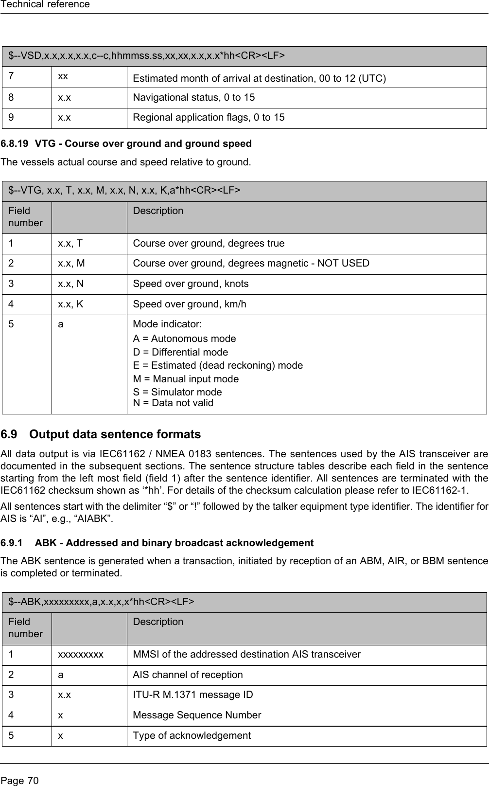
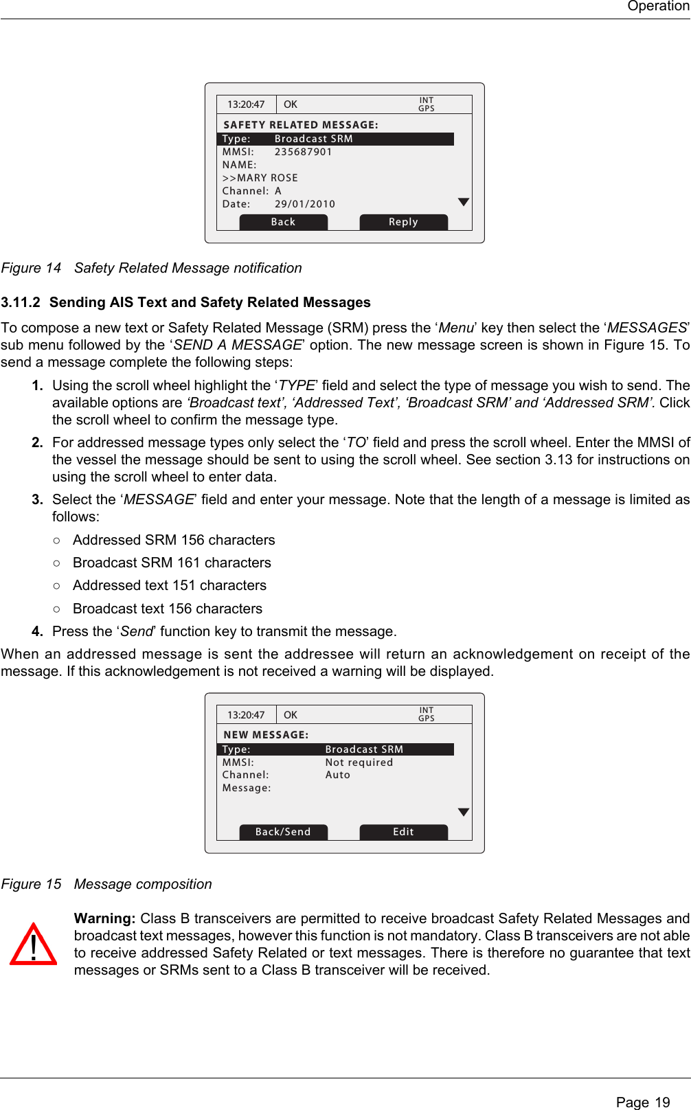
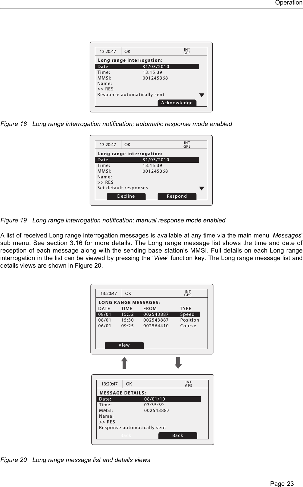
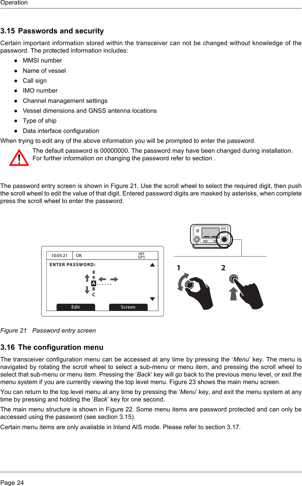
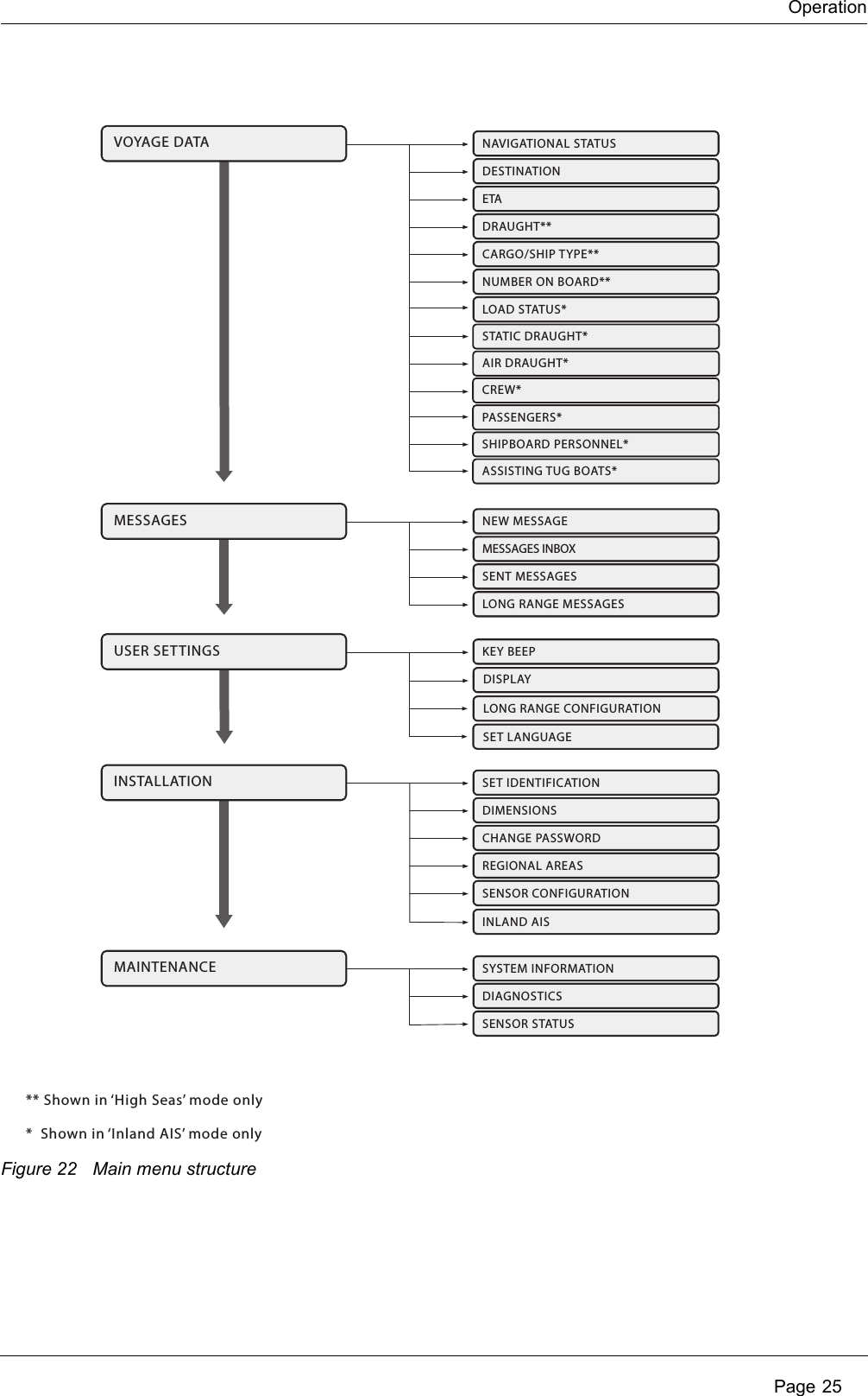
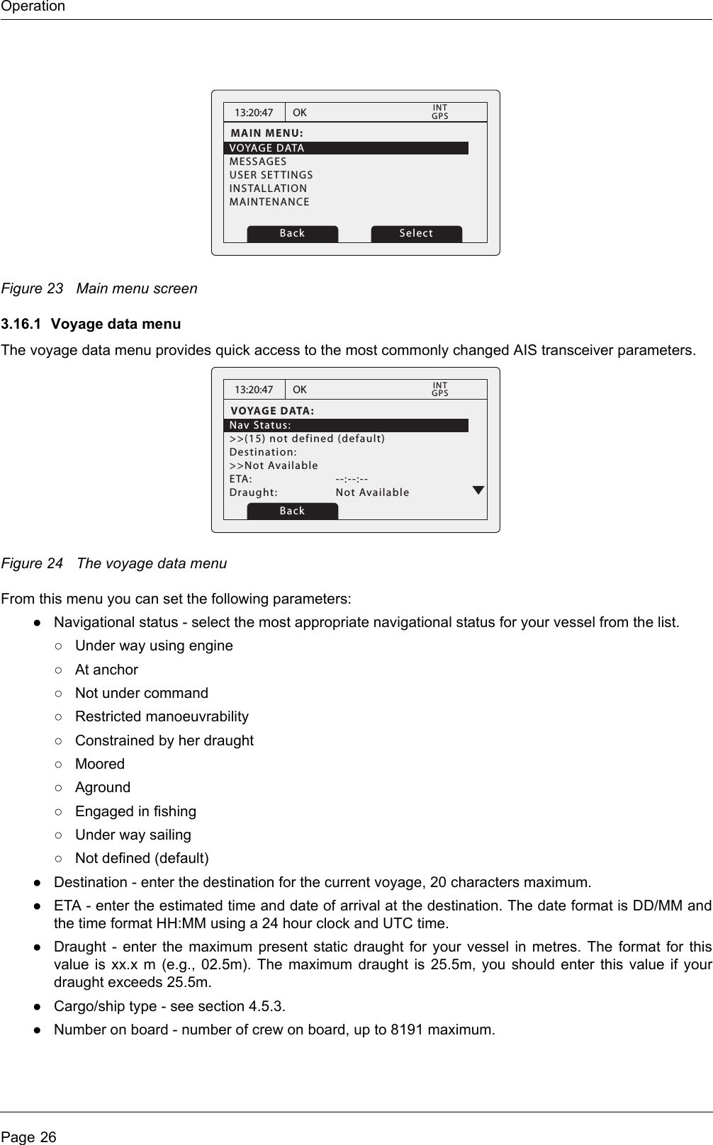
![OperationPage 183.10 Target plot screenThe target plot screen shows the location of other AIS equipped vessels and shore stations relative to your ownvessel. The target plot screen provides a basic overview of AIS targets and should not be regarded as asubstitute for display of AIS information on a dedicated electronic chart display system (ECDIS).Figure 12 Target plot screenThe plot range can be adjusted by pressing the ‘Range’ function key which cycles through the ranges 48, 24,12, 6, 3, 1 and 0.5nm. The range relates to radius of the outer range ring shown on the screen.Individual targets can be selected using the scroll wheel. When selected a square outline will appear aroundthe target, pressing the scroll wheel will display full vessel details. To return to the target plot screen from thevessel details screen press the back key.Different symbols are displayed for an AIS target depending on the type of target and its status, these areshown in Figure 13. The own vessel symbol is always shown at the centre of the plot.Figure 13 Target plot symbols3.11 Working with AIS text and Safety Related Messages (SRMs)AIS text messages and Safety Related Messages (SRMs) can be received from other AIS equipped vesselsand also sent to specific vessels (addressed messages) or sent to all vessels in range (broadcast messages).3.11.1 Receiving AIS text and Safety Related MessagesReception of an AIS text message is indicated by the presence of the message icon in the status bar. This iconis shown whenever there are unread AIS text messages. Messages can be reviewed and replied to via themessages screen; see section 3.8. When a Safety Related Message is received the user will be notified immediately with a screen showing themessage. Standard text messages are not displayed on receipt, however the message icon will be displayedon the status bar.Range ScreenName of selected target MMSI of selected targetHeading line (points up to signify heading up)Selected target[HDG UP] 27 Tgts10nmMARY ROSE 235687901Number of targets on displayRange selection keyheading up modeRange selectedLost target (vessel)Target (vessel)Own vesselAtoNBase stationSART](https://usermanual.wiki/SRT-Marine-Systems-plc/405-0002.Installation-and-users-guide/User-Guide-1279988-Page-18.png)
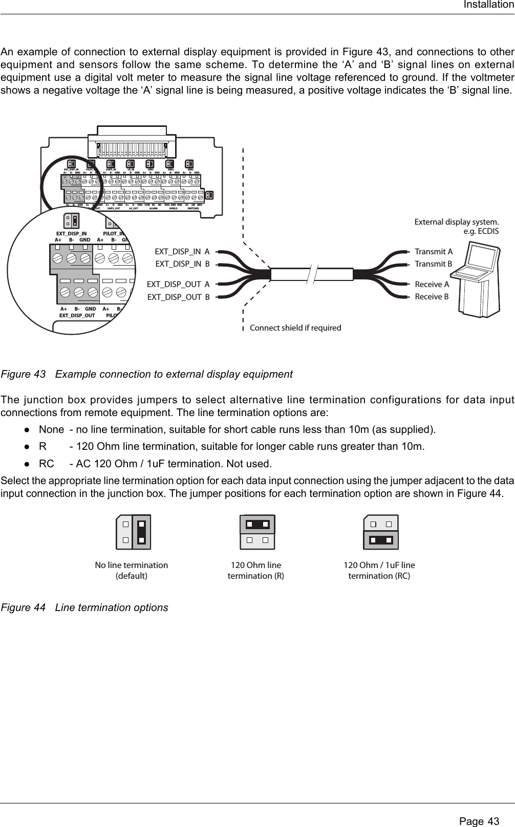
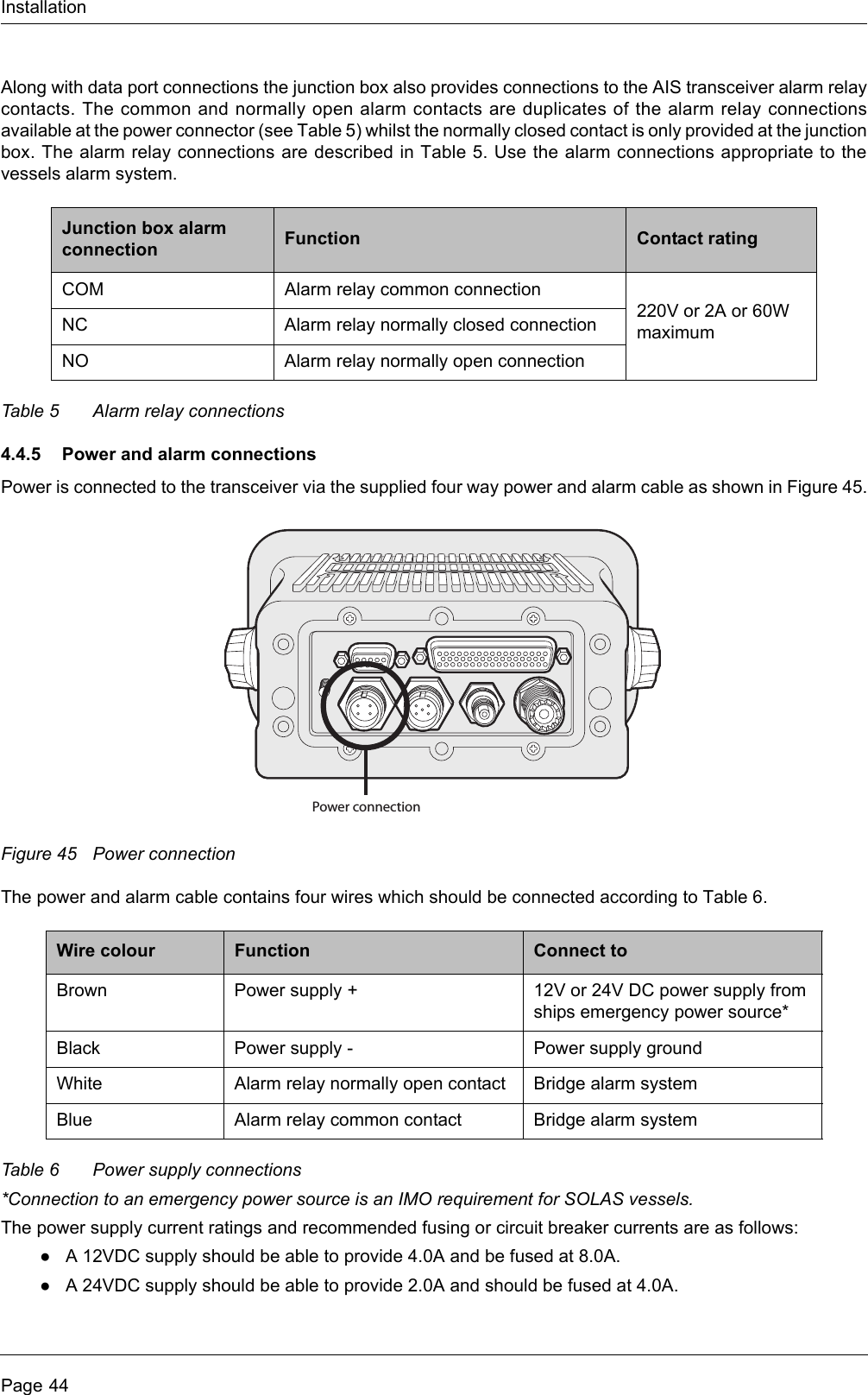
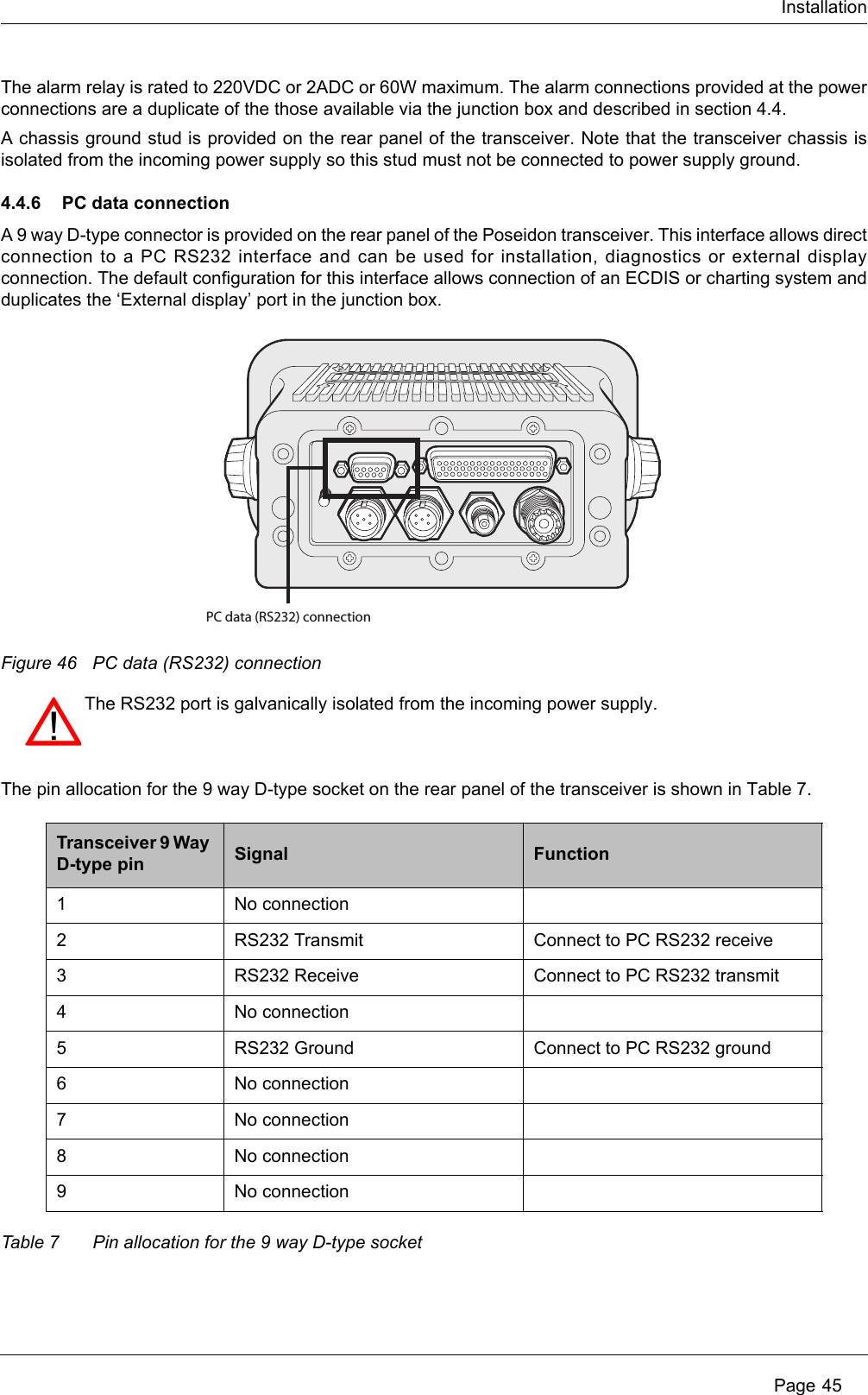
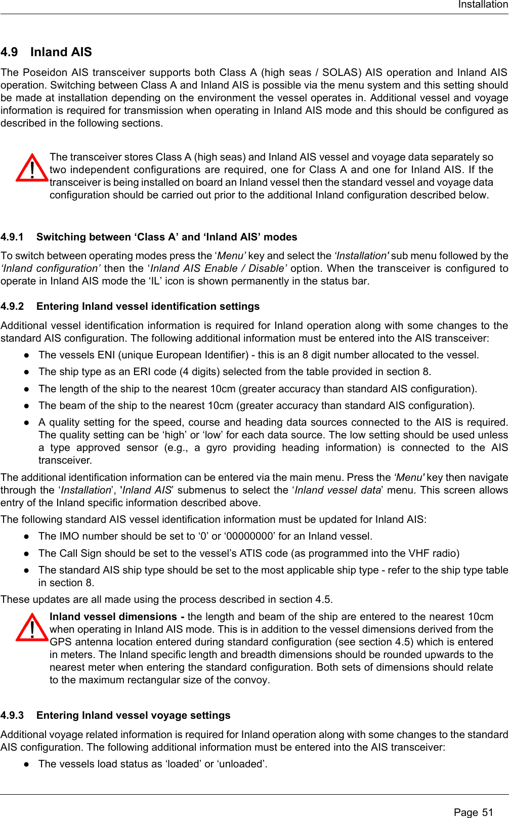
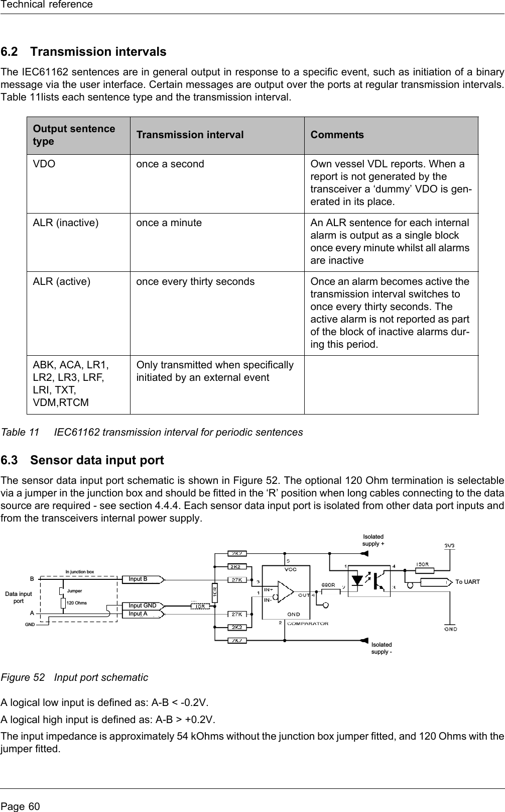
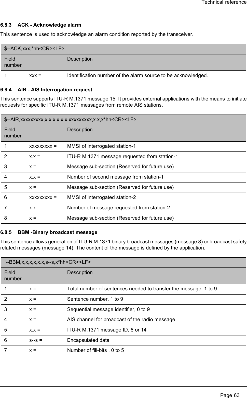
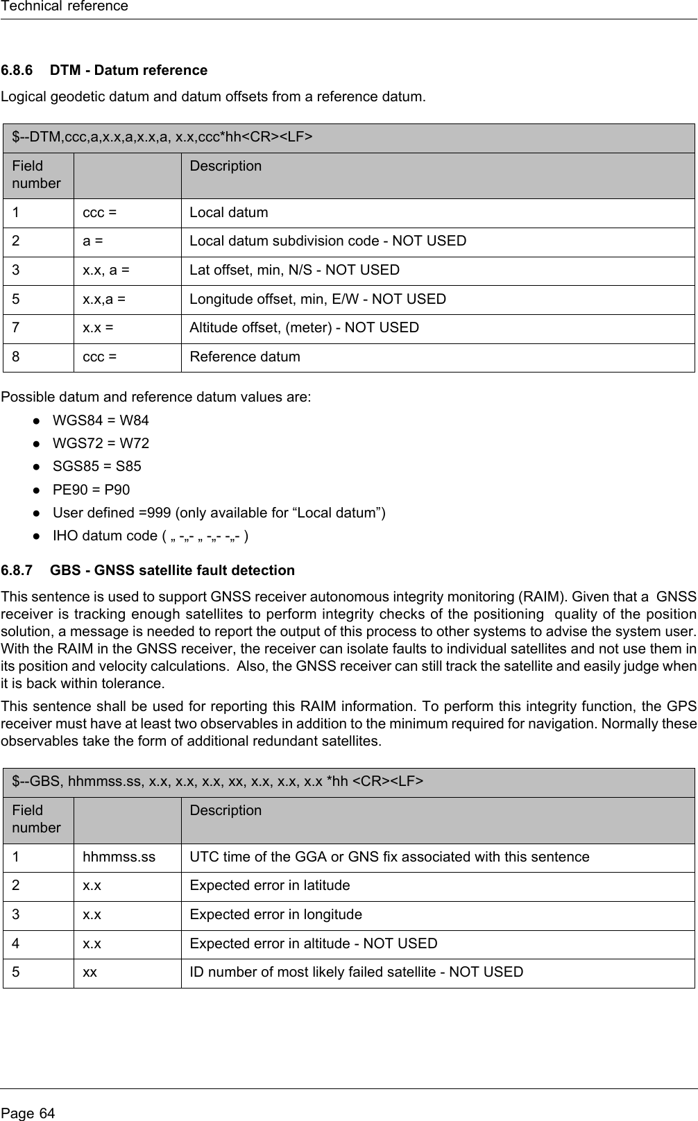
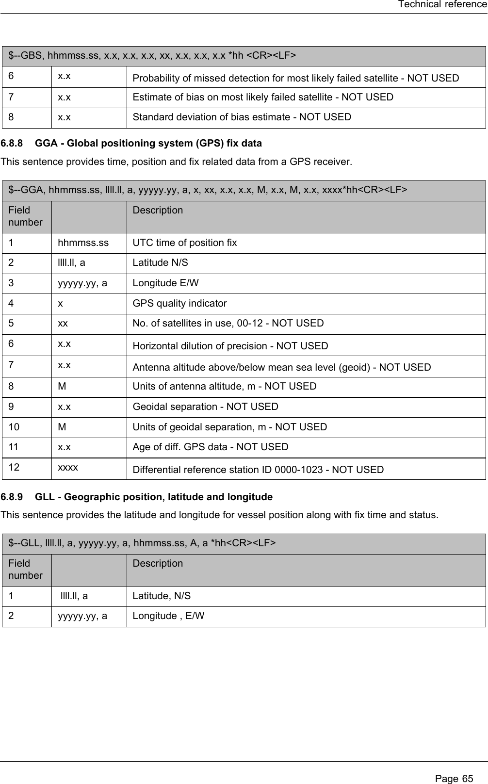
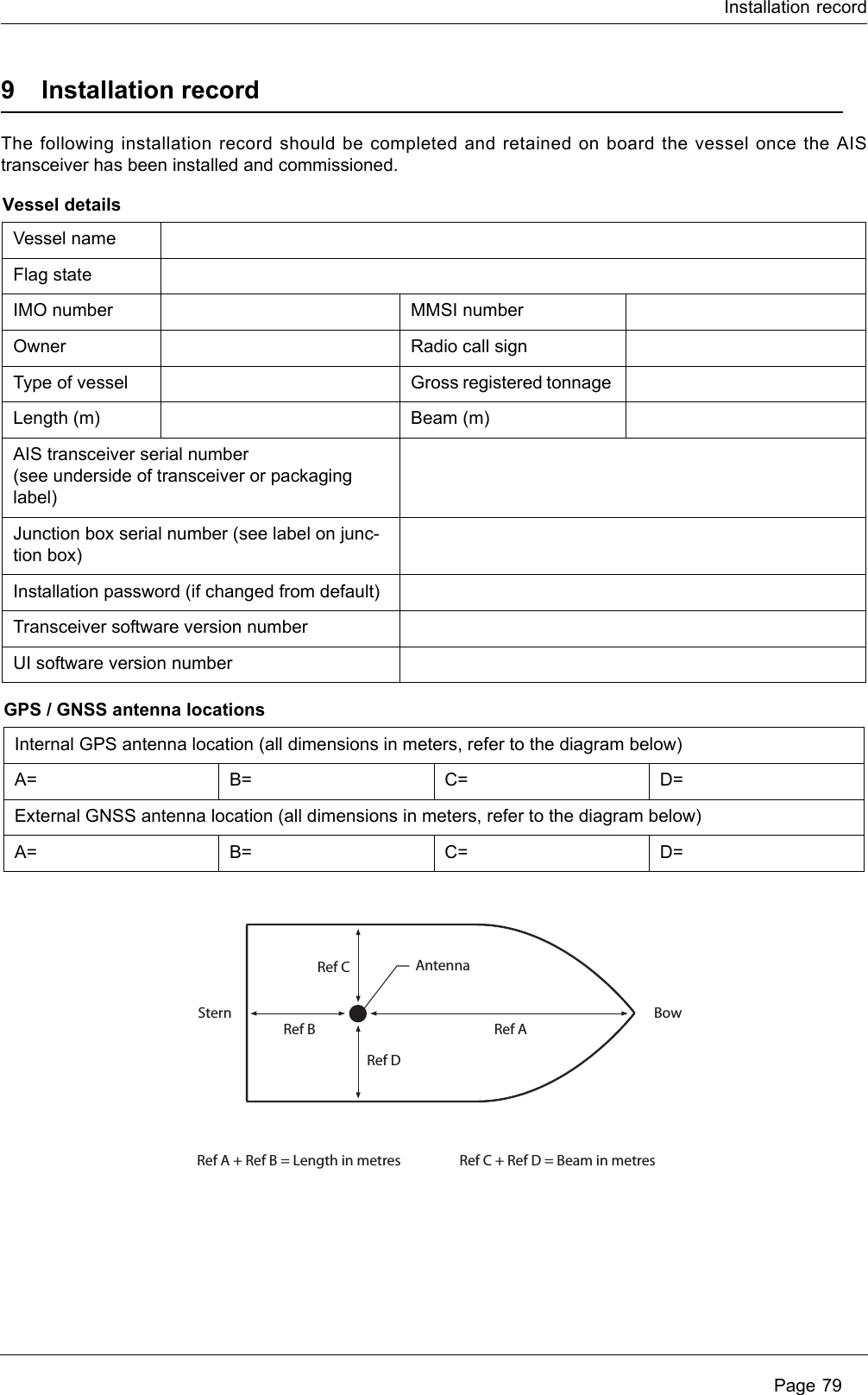
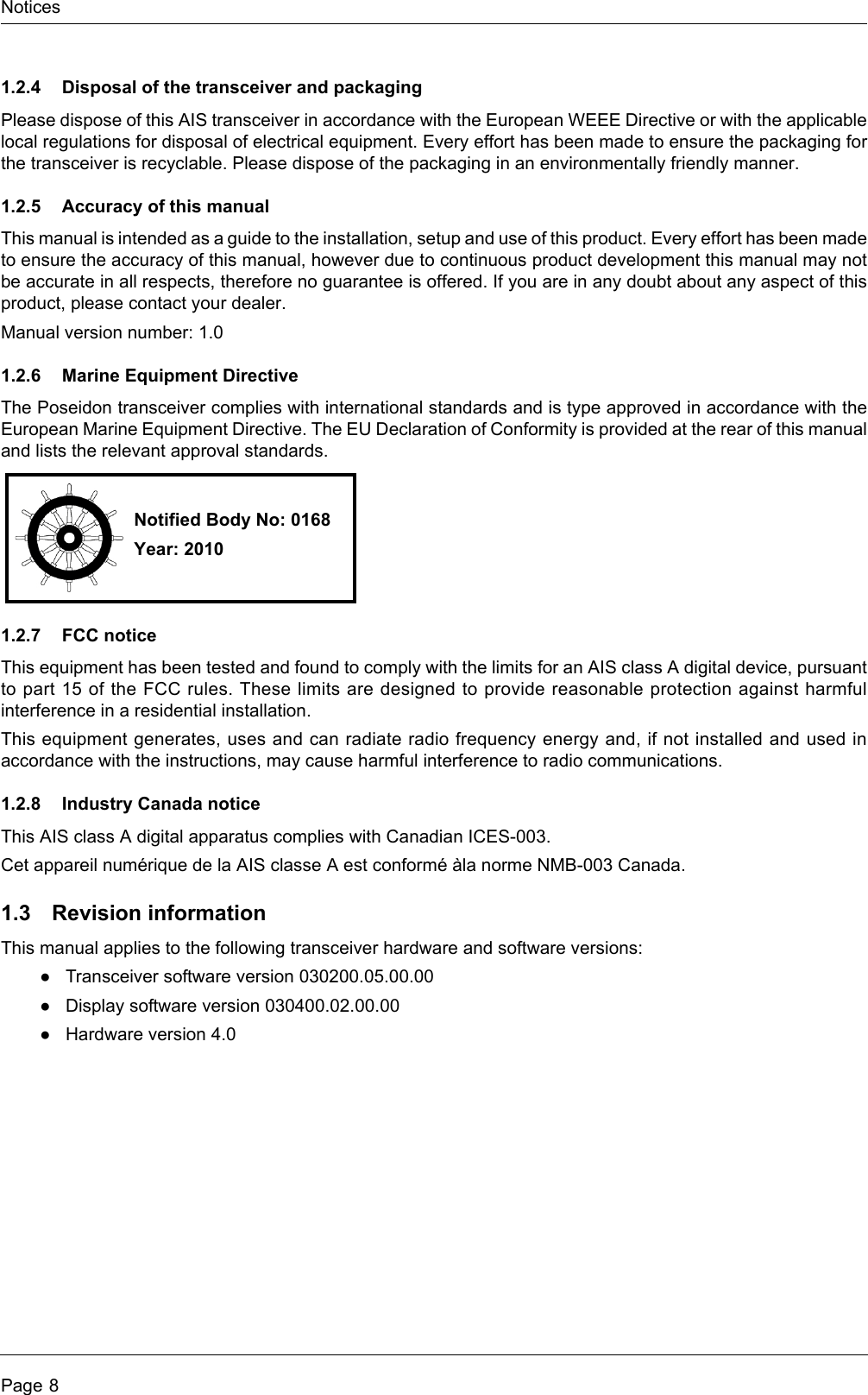
![InstallationPage 47To enter the GNSS antenna locations go back to the main menu and select the ‘Dimensions’ then ‘Internal’ or'External’ option as appropriate. Dimensions for both the internal and external GNSS antennas must be enteredif an external GNSS is connected to the AIS transceiver. The antenna dimensions should be entered in metresaccording to the diagram provided in Figure 47. Figure 47 Vessel dimensions measurement4.5.3 Configure voyage related dataThe transceiver must be configured with information about its voyage prior to operation. The followinginformation is required:●Nav Status - Navigational status selected from the list below:○0 - Under way using engine.○1 - At anchor.○2 - Not under command.○3 - Restricted manoeuvrability.○4 - Constrained by her draught.○5 - Moored.○6 - Aground.○7 - Engaged in fishing.○8 - Under way sailing.○9 to 14 - reserved for future use.○15 - not defined (default setting).●Destination - Ships next destination port (limited to 20 characters).●ETA - Estimated time / date of arrival at destination (using UTC time).●Draught - Maximum present static draught to the nearest 1/10th of a metre.●Ship and cargo type - a two digit code selected using Table 8. Where the second digit is representedby [n] the appropriate code for the second digit should be selected from Table 9. ●Crew - Number of crew on board (optional).To enter the vessel identification information press the ‘Menu’ key and select the ‘Voyage Data’ option. Thevessels Nav. status, Destination, ETA, Draught, Type and number of crew can then be entered.Ref AAntennaRef A + Ref B = Length in metres Ref C + Ref D = Beam in metresRef BStern BowRef CRef D](https://usermanual.wiki/SRT-Marine-Systems-plc/405-0002.Installation-and-users-guide/User-Guide-1279988-Page-47.png)
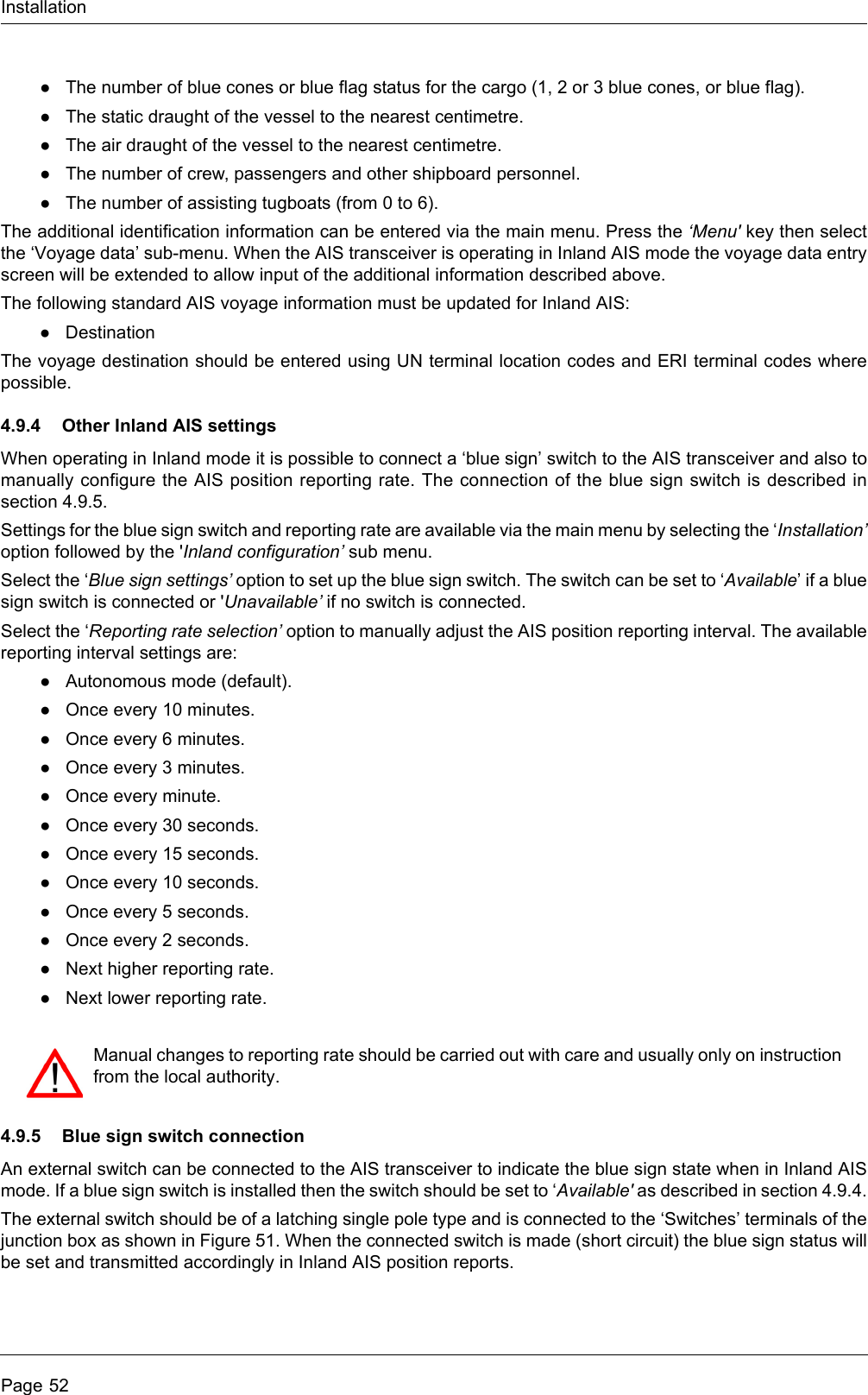
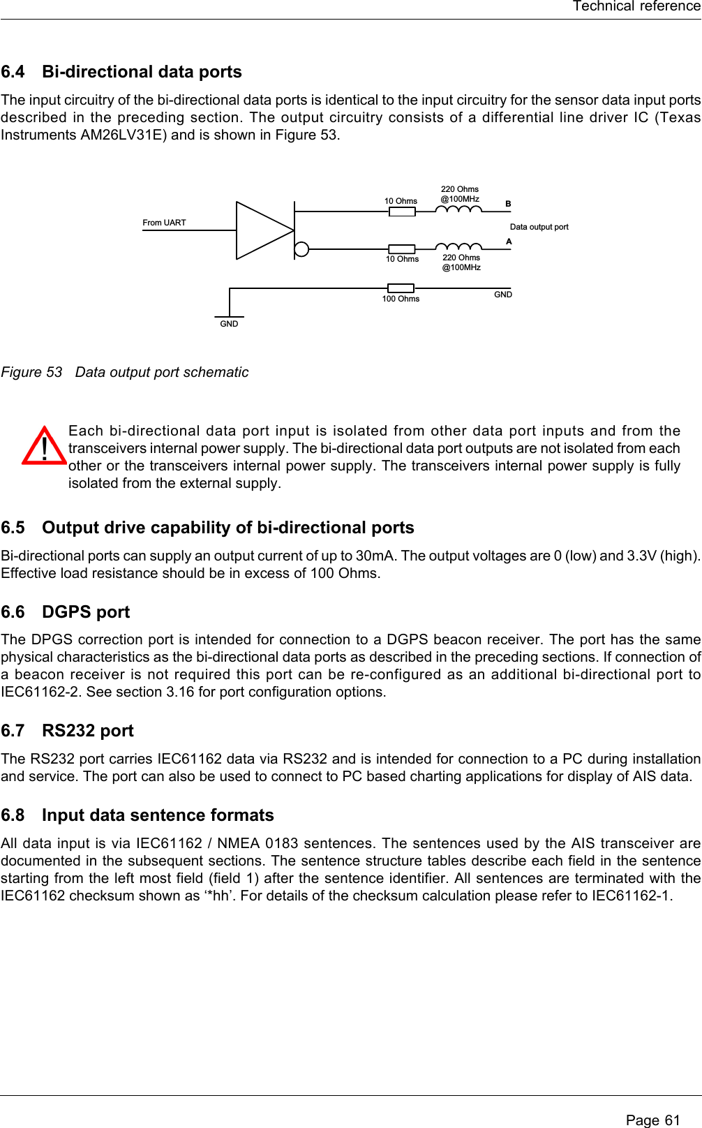
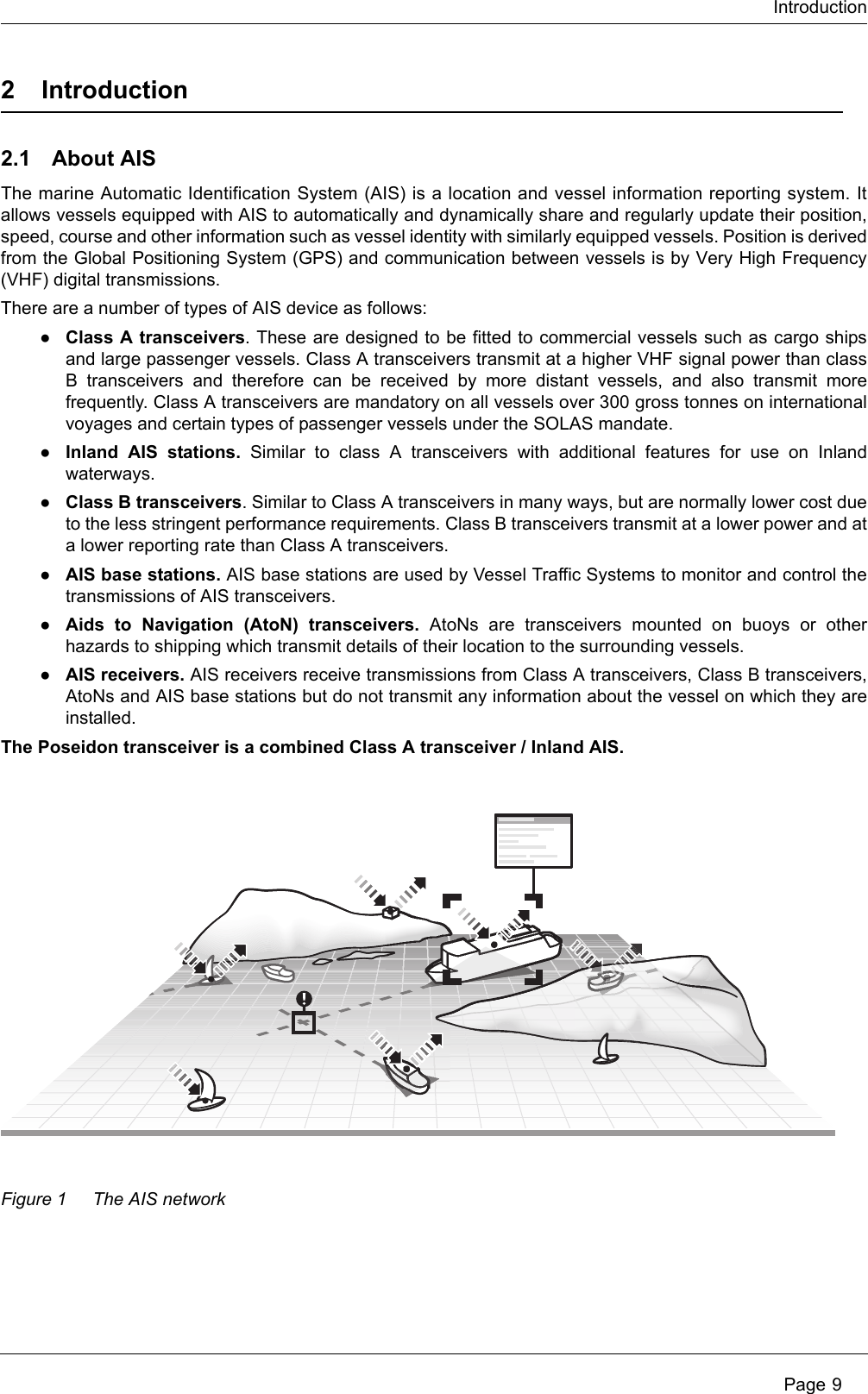
![InstallationPage 48Table 8 Vessel types and their corresponding vessel type codesTable 9 Type codes for vessels carrying cargoVessel type Type codeReserved (do not use) 1[n]Wing in ground craft 2[n]Fishing 30Towing 31Towing and length of tow exceeds 200m or breadth exceeds 25m 32Engaged in dredging or underwater operations 33Engaged in diving operations 34Engaged in military operations 35Sailing 36Pleasure craft 37(HSC) High speed craft 4[n]Pilot vessel 50Search and rescue vessel 51Tug 52Port tender 53Vessel with anti-pollution facilities 54Law enforcement vessel 55Spare - for local use 56Spare - for local use 57Medical transports (under the 1949 Geneva conventions and additional protocols) 58Ships according to RR Resolution No. 18 (Mob-83) - Relating to the Procedure for Identifying and Announcing the Position of Ships and Aircraft of States Not Parties to an Armed Conflict59Passenger ship 6[n]Cargo ship 7[n]Tanker 8[n]Other type of ship 9[n]Cargo type Second digit(where not predefined)All ships of this type 0Carrying DG, HS, or MP, IMO hazard or pollutant category A 1Carrying DG, HS, or MP, IMO hazard or pollutant category B 2Carrying DG, HS, or MP, IMO hazard or pollutant category C 3Carrying DG, HS, or MP, IMO hazard or pollutant category D 4Reserved (do not use) 5Reserved (do not use) 6Reserved (do not use) 7Reserved (do not use) 8No additional information 9](https://usermanual.wiki/SRT-Marine-Systems-plc/405-0002.Installation-and-users-guide/User-Guide-1279988-Page-48.png)