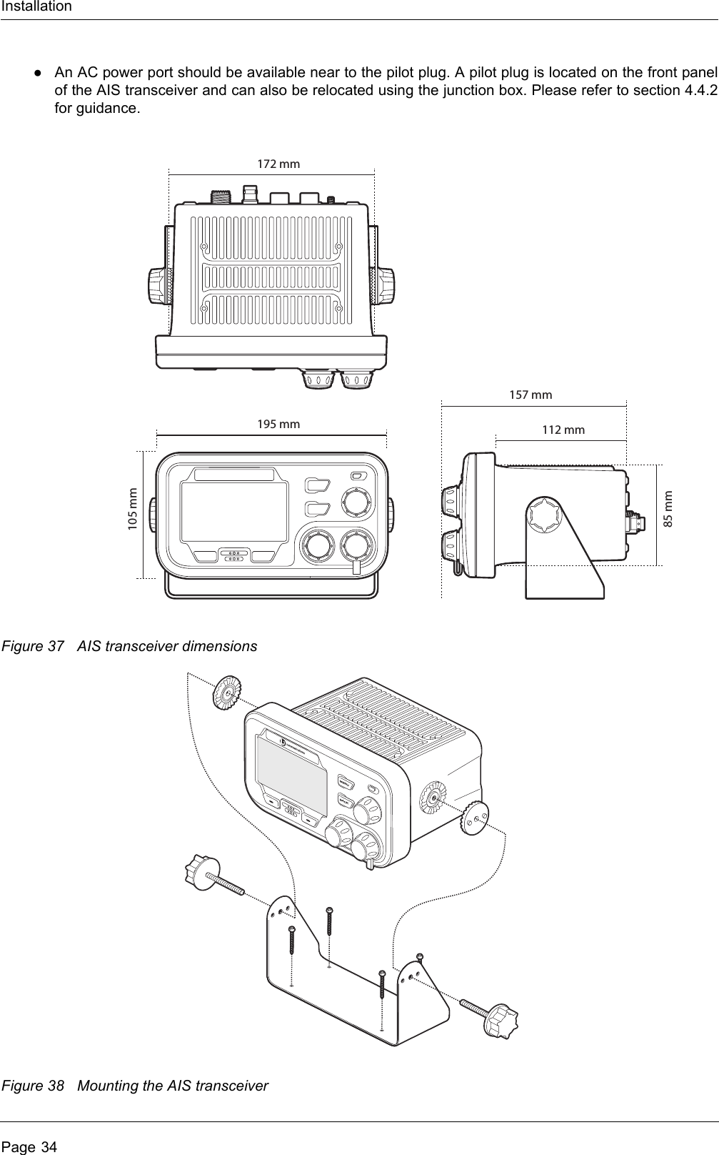
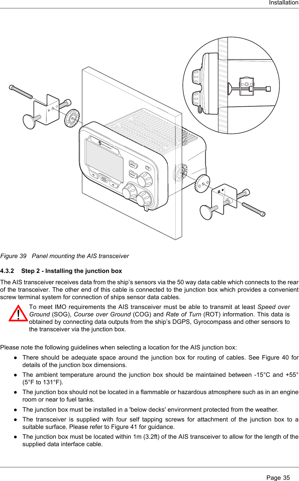
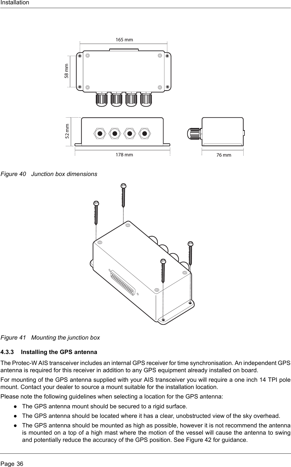
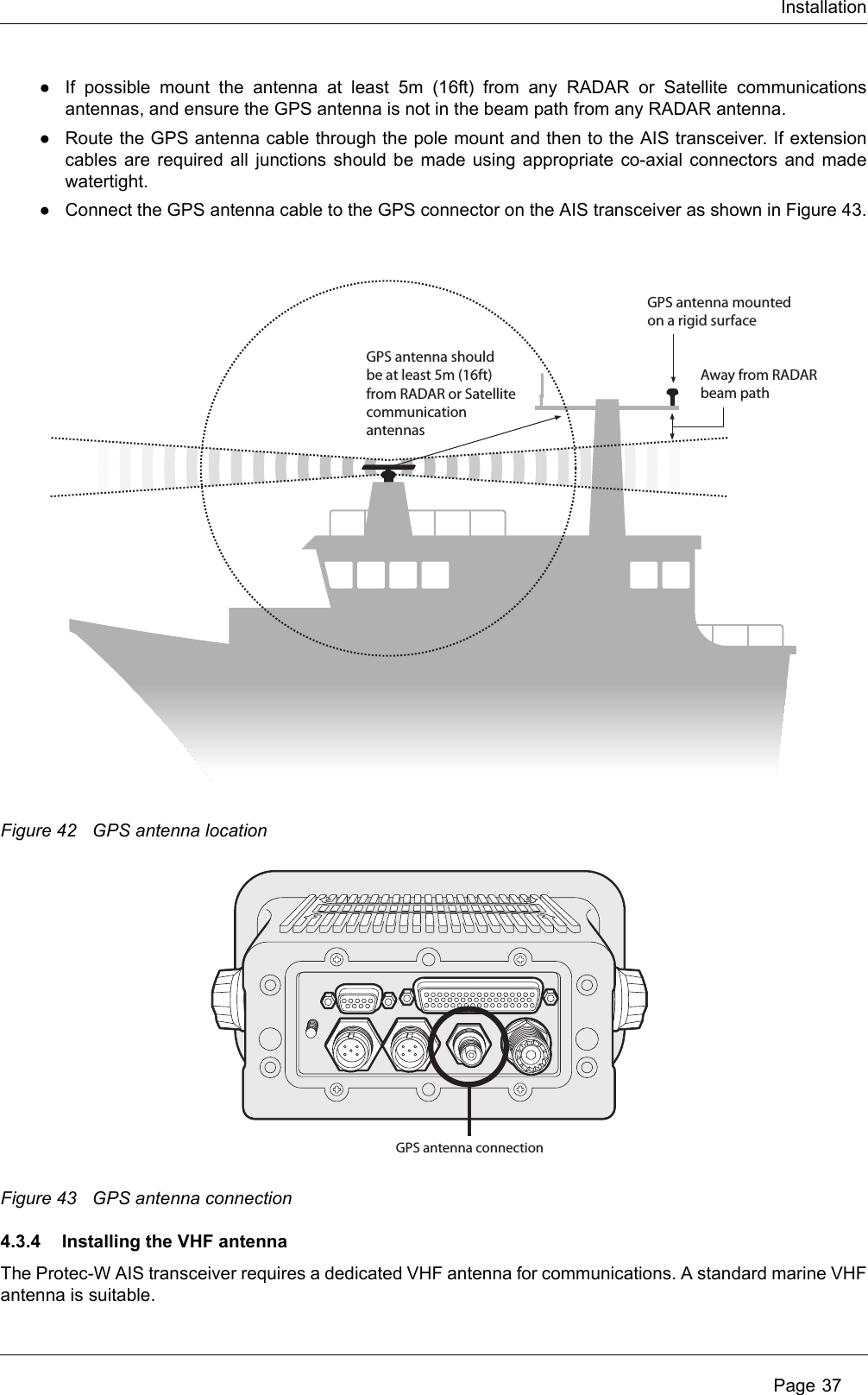
SRT Marine Systems plc 405-0002 PROTEC-W AIS Class A CS User Manual L3 custom posiedon manual English
Software Radio Technology plc PROTEC-W AIS Class A CS L3 custom posiedon manual English
Contents
- 1. Installation and users guide
- 2. User manual
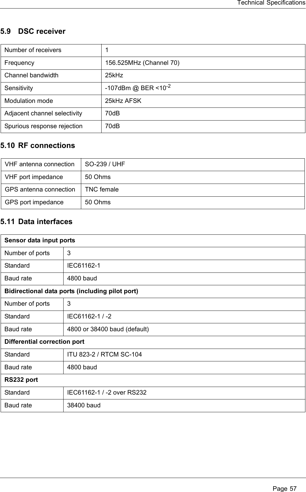
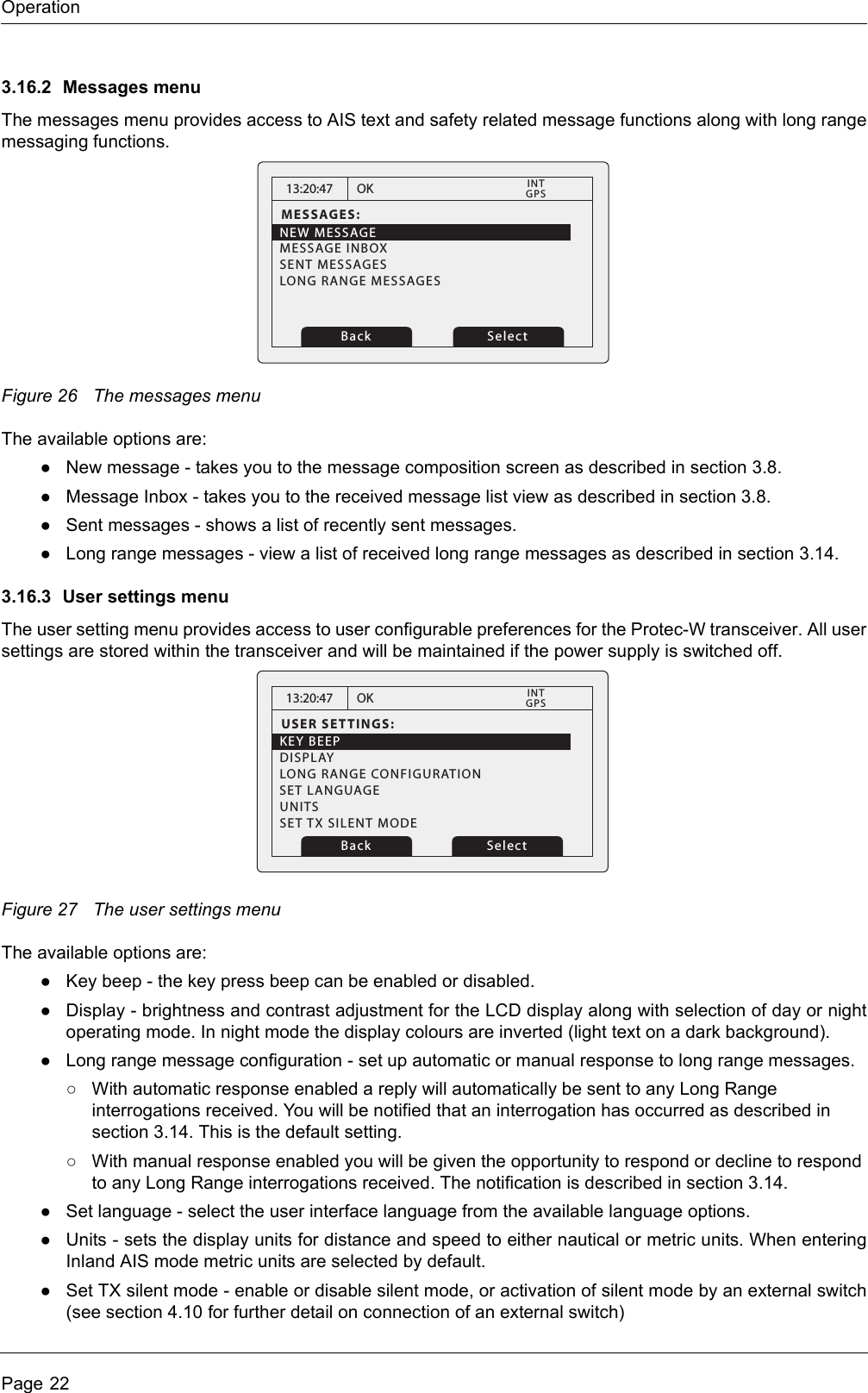
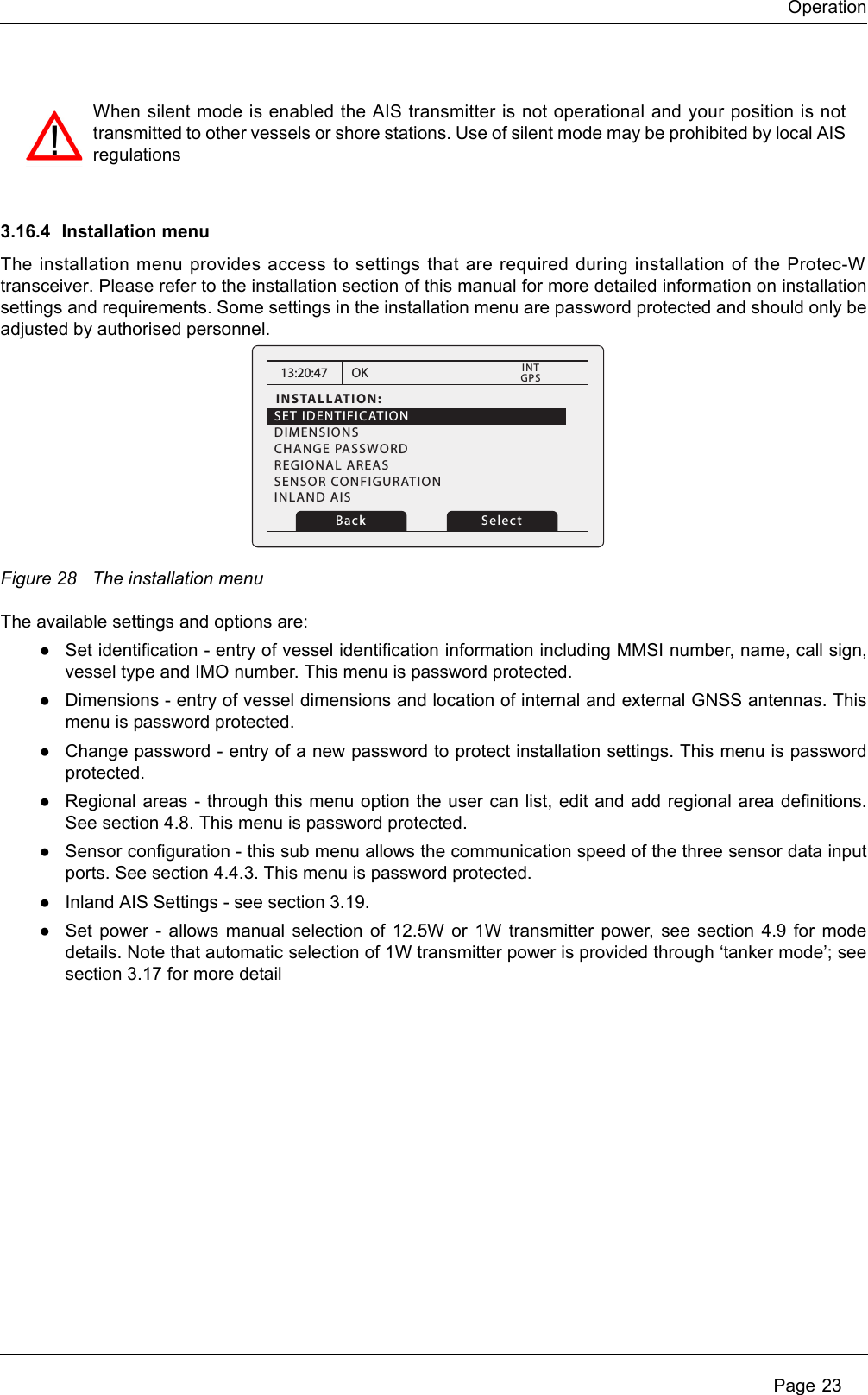
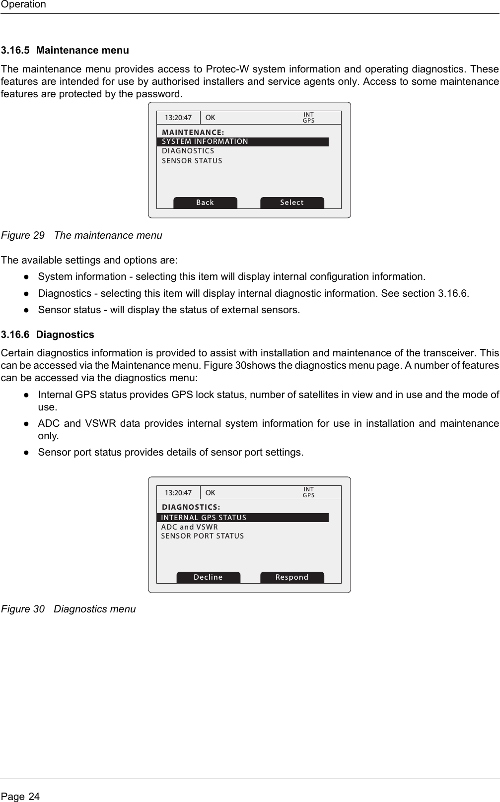
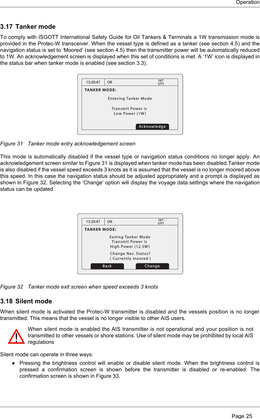
User manual


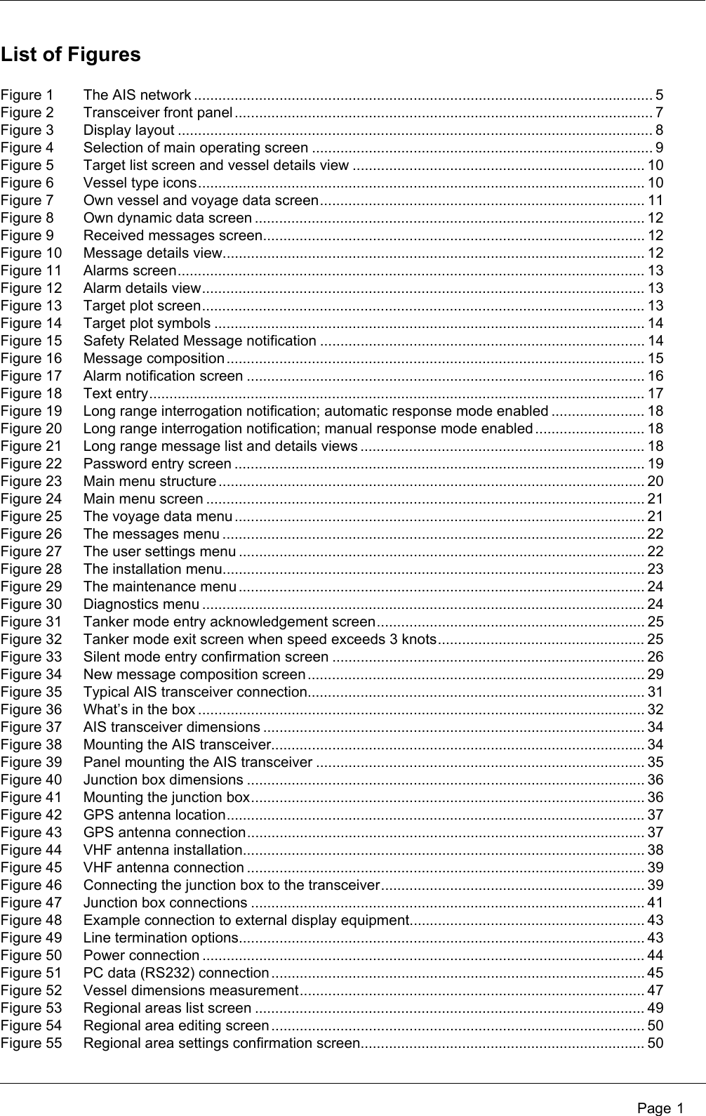


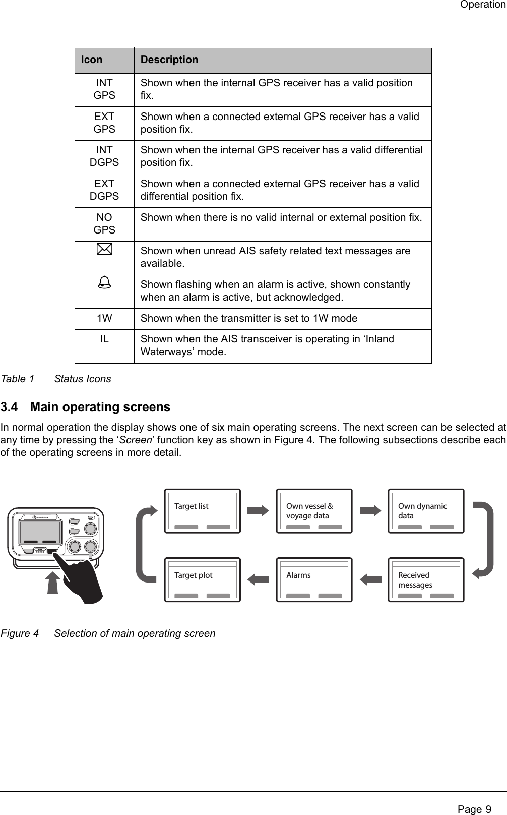
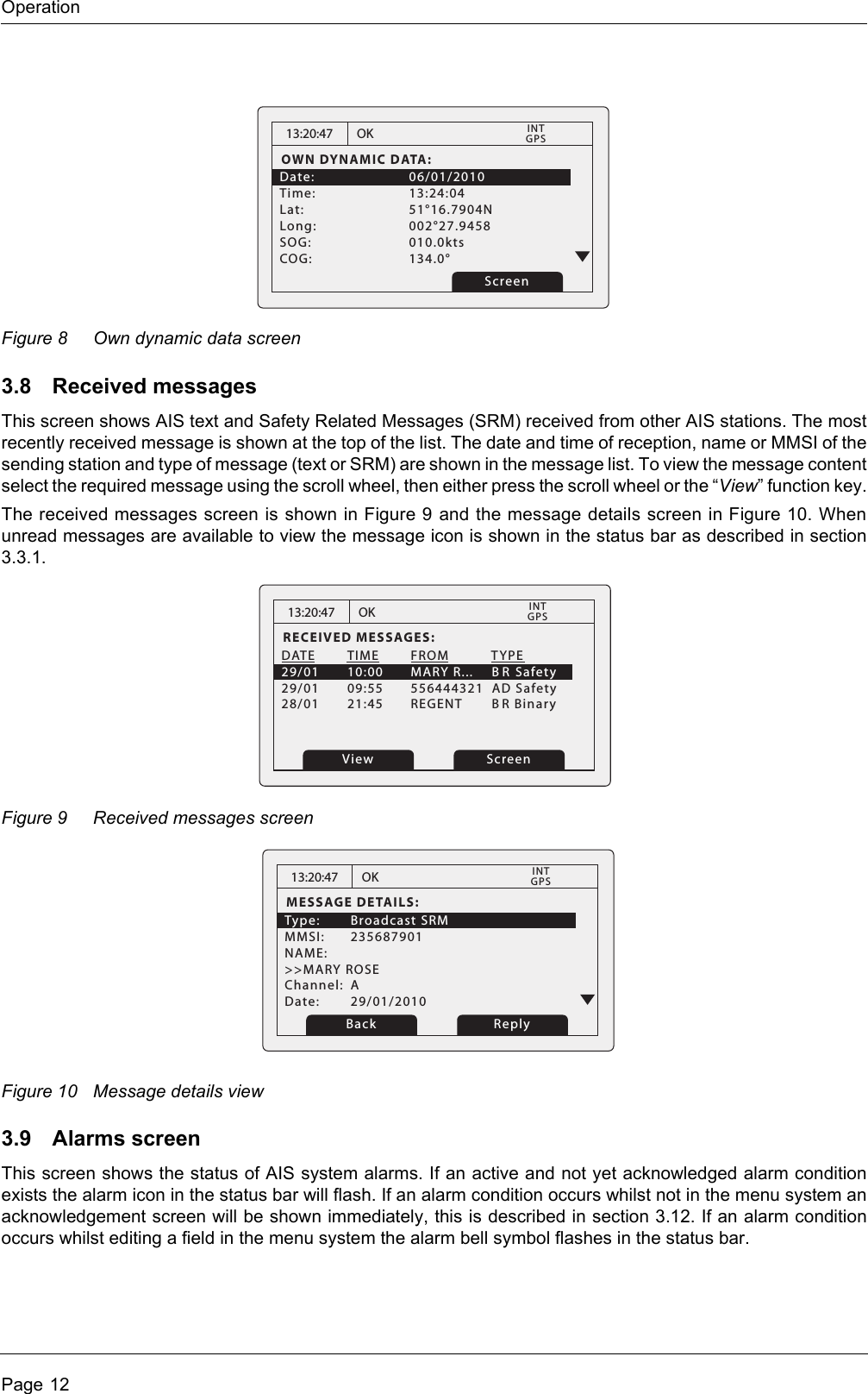
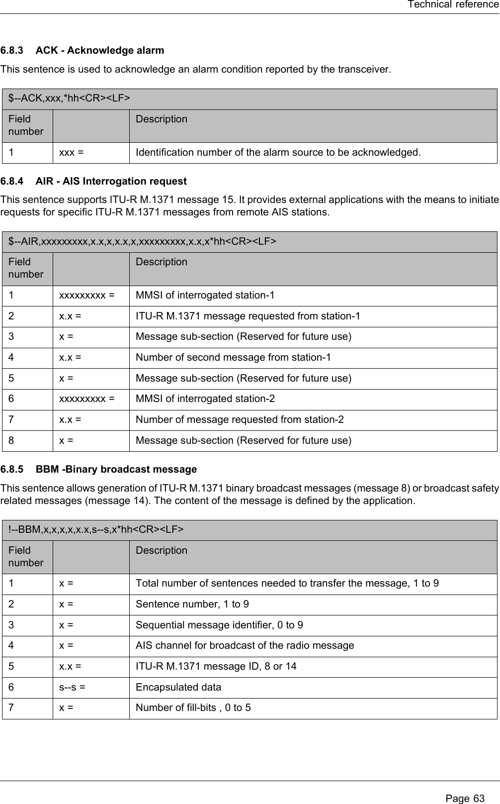
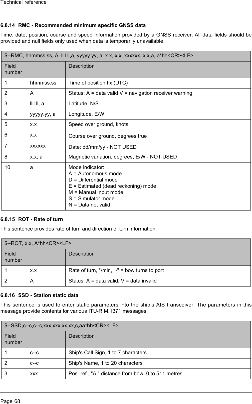
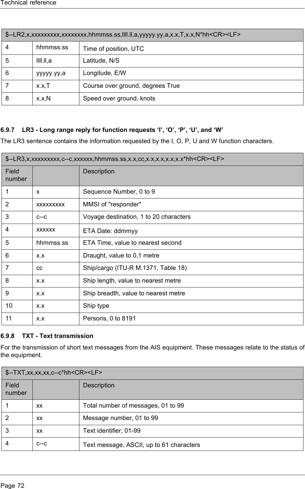
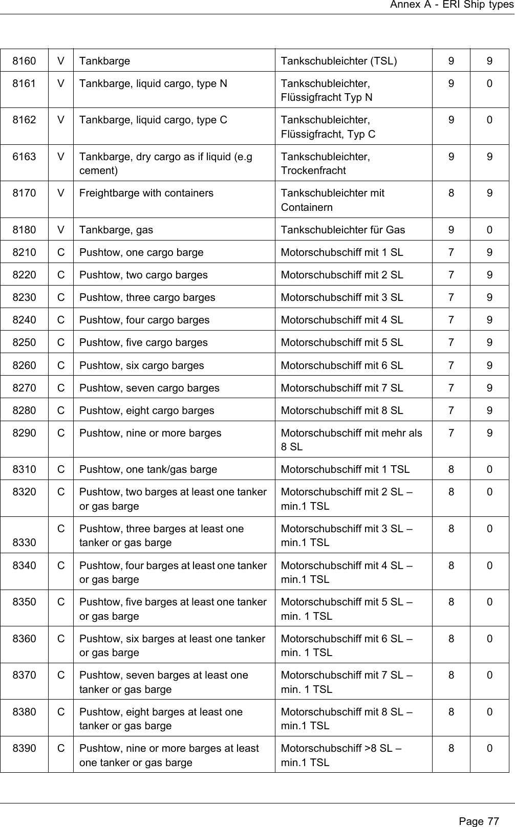
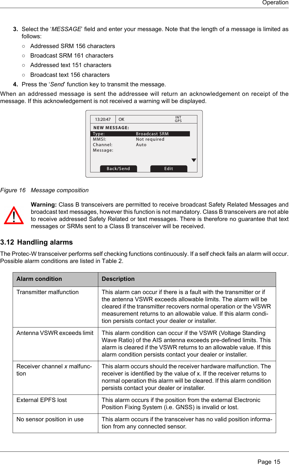
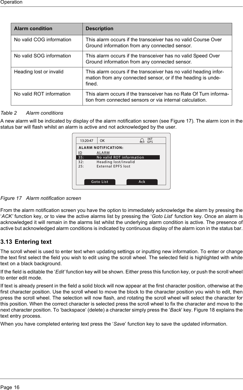
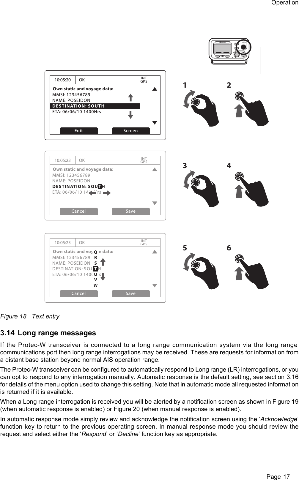
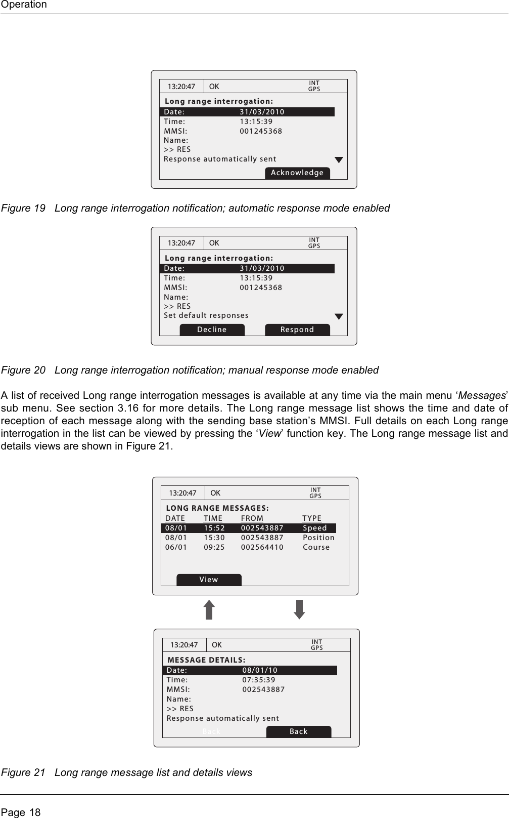
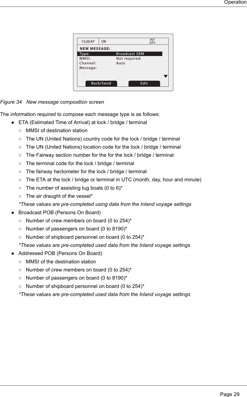
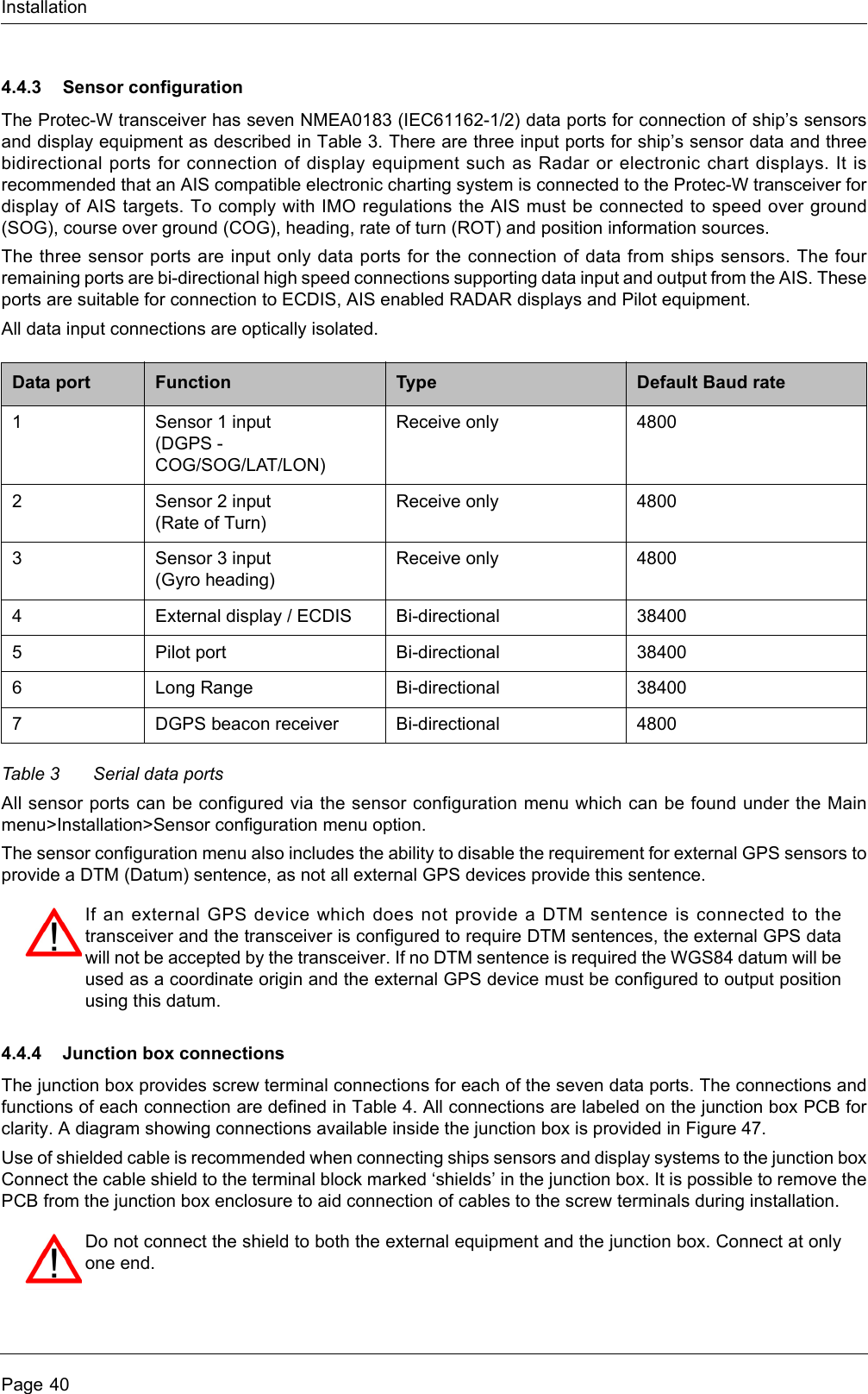
![Operation Page 13The alarms screen shows the date and time of activation along with a brief description of any active alarm and it’s acknowledge state — see Figure 11. Alarms that are active but not acknowledged by the operator have ‘No’in the ‘Ack’ column. Once an alarm is acknowledged by the operator ‘Yes’ is displayed in the ‘Ack’ column. An individual alarm can be selected from the list using the scroll wheel and it’s details viewed by either pressing the scroll wheel or the “View” function key. The alarm details view is shown in Figure 12.Figure 11 Alarms screenFigure 12 Alarm details view3.10 Target plot screenThe target plot screen shows the location of other AIS equipped vessels and shore stations relative to your own vessel. The target plot screen provides a basic overview of AIS targets and should not be regarded as a substitute for display of AIS information on a dedicated electronic chart display system (ECDIS).Figure 13 Target plot screen13:20:47ALARMS LIST:DATE TIME ALARM ACK25/11 16:13 No valid ROT... Yes25/11 16:11 Heading lost... Yes25/11 16:11 External EPFS... YesOK GPSINTView Screen13:20:47ALARM DETAILS:ALARM: No valid ROT informationID: 35DATE: 25/11/2010TIME: 16:13:30ACK: YesOK GPSINTExitWhile alarm conditions are active and un-acknowledged, any connected external alarm system will remain activated.Range ScreenName of selected target MMSI of selected targetHeading line (points up to signify heading up)Selected target[HDG UP] 27 Tgts10nmMARY ROSE 235687901Number of targets on displayRange selection keyheading up modeRange selected](https://usermanual.wiki/SRT-Marine-Systems-plc/405-0002.User-manual/User-Guide-1366566-Page-17.png)

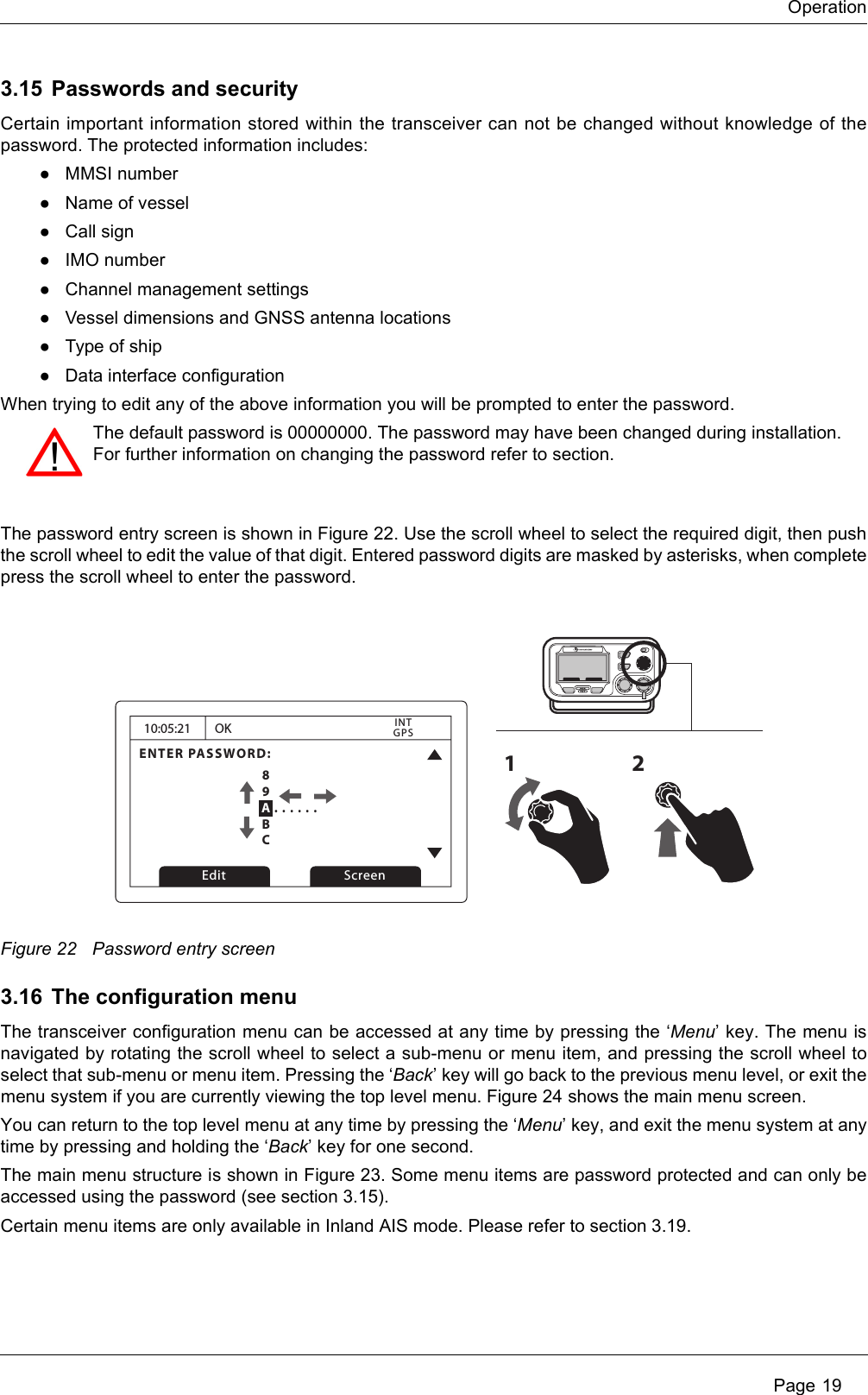


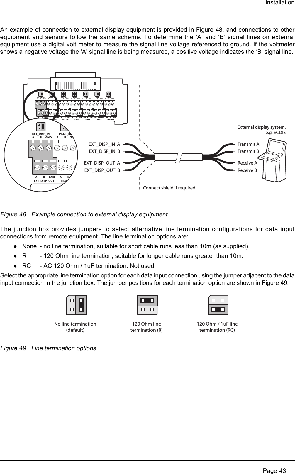
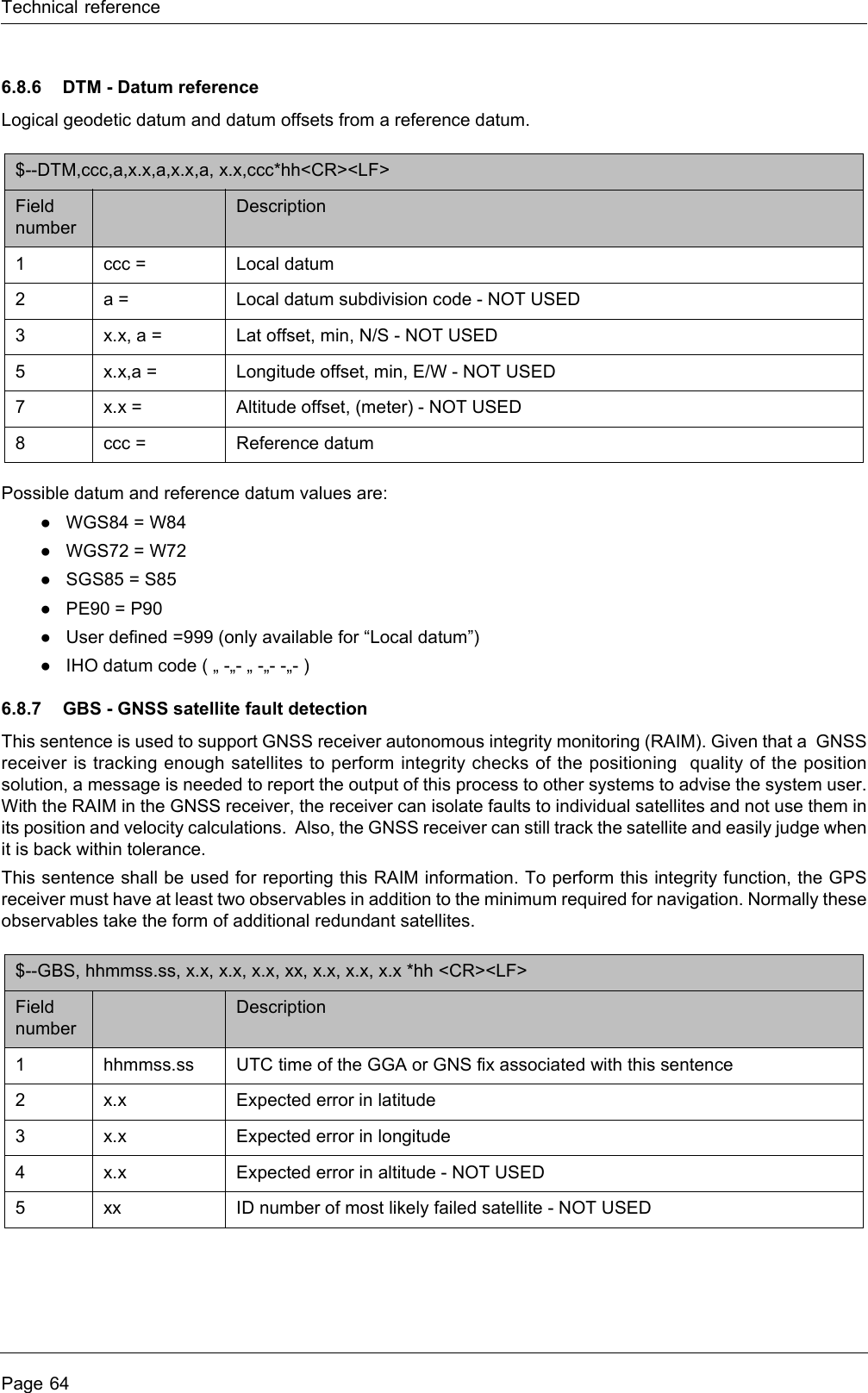
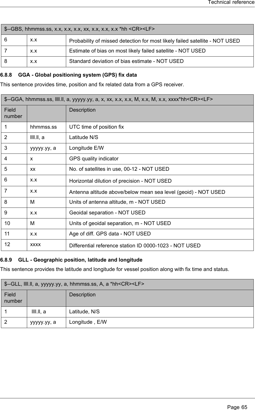
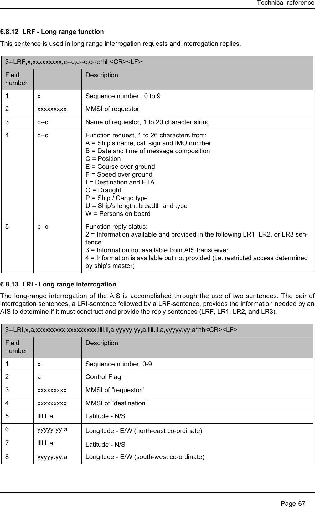
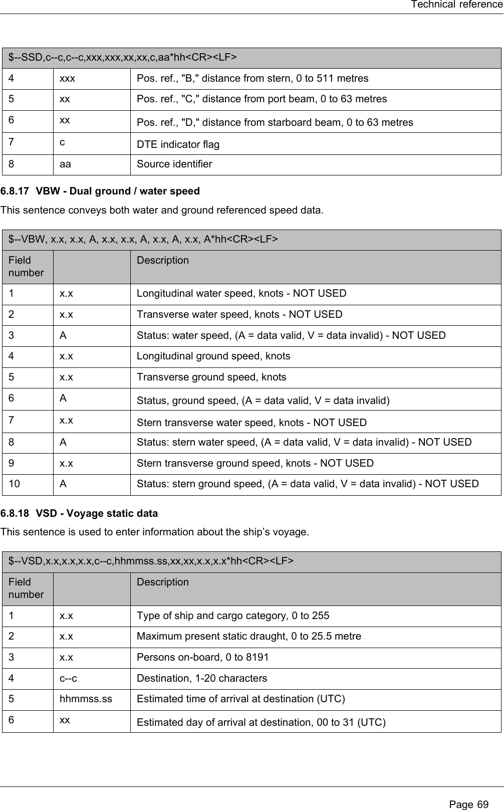
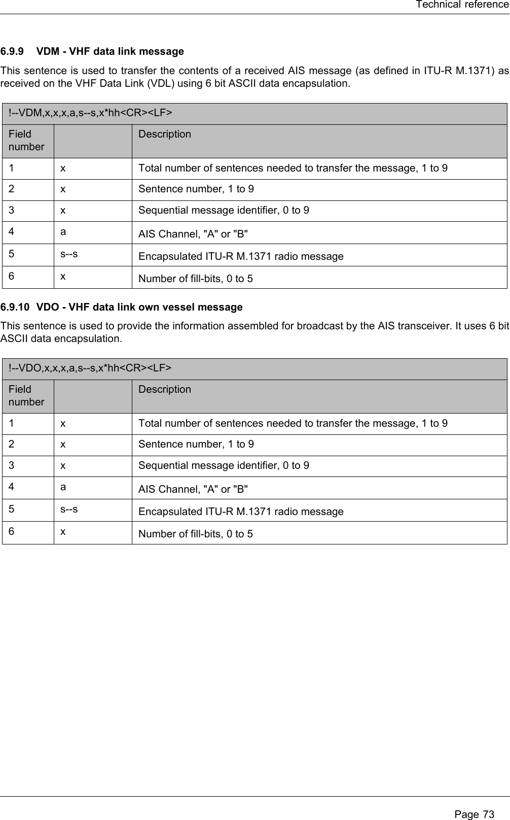
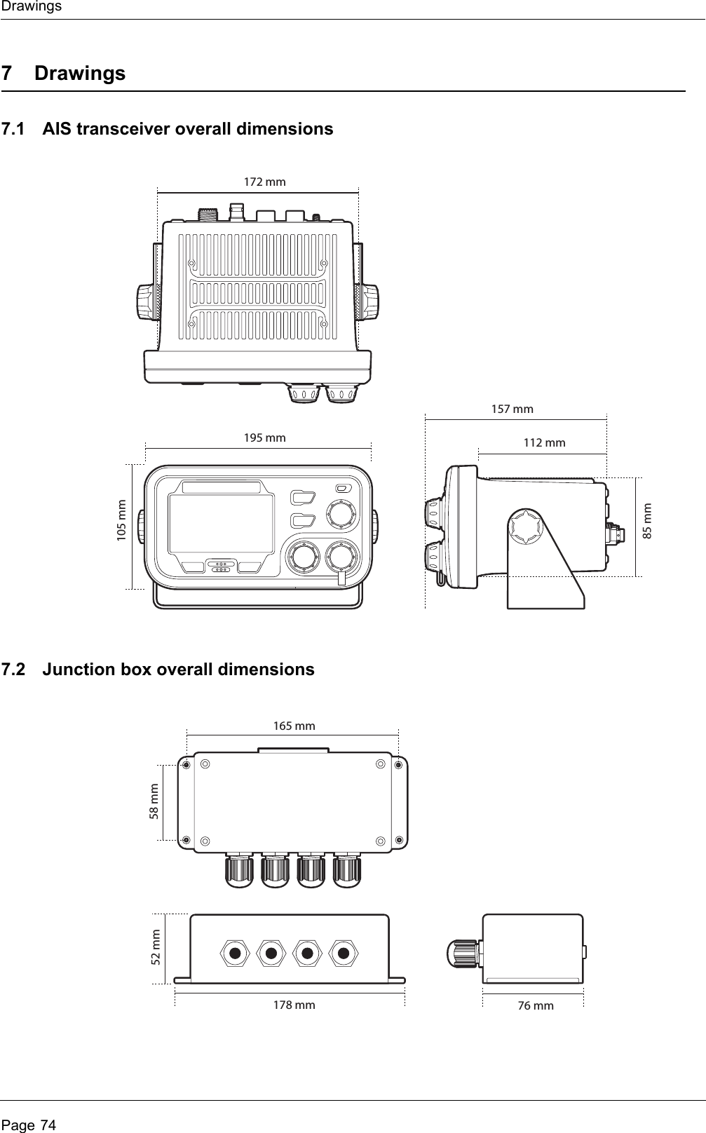
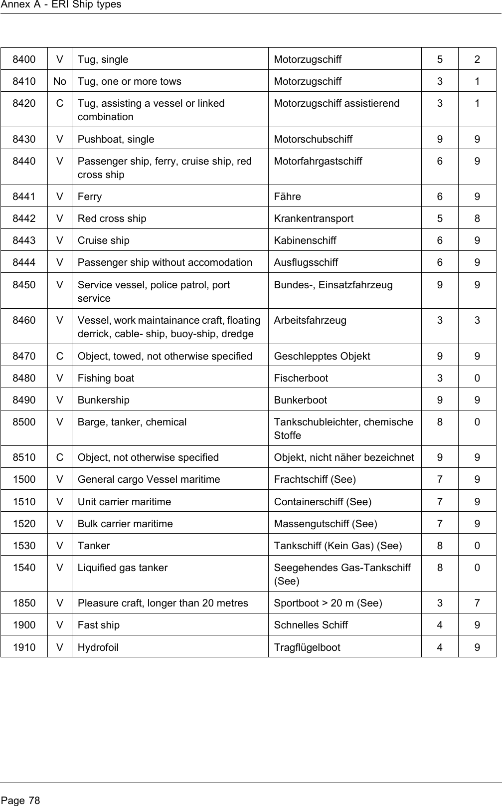
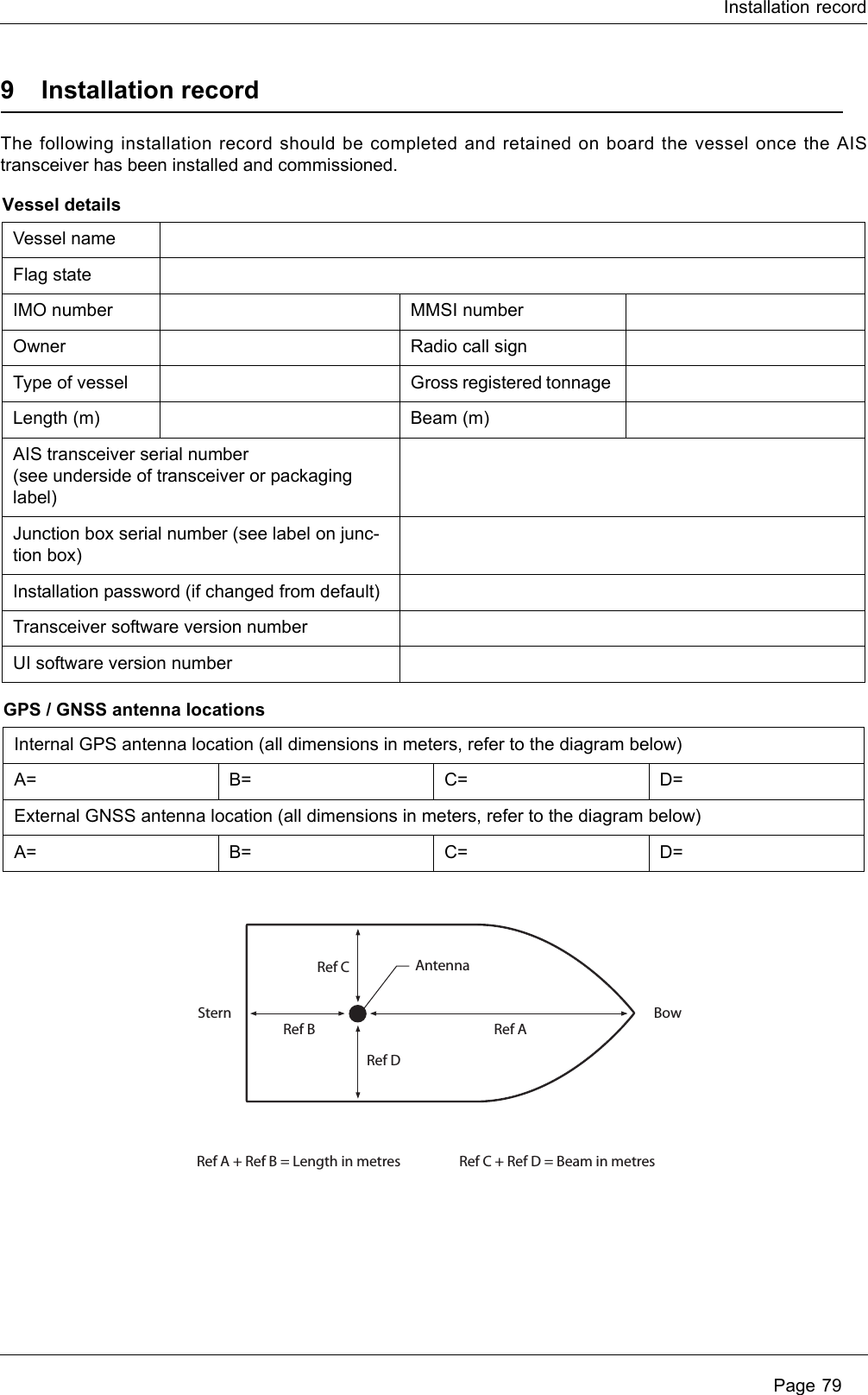
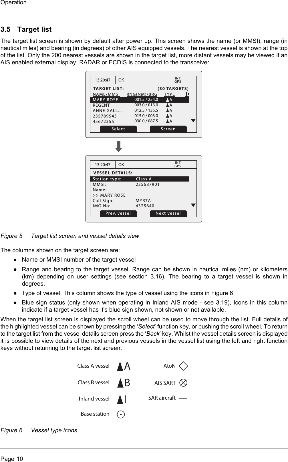
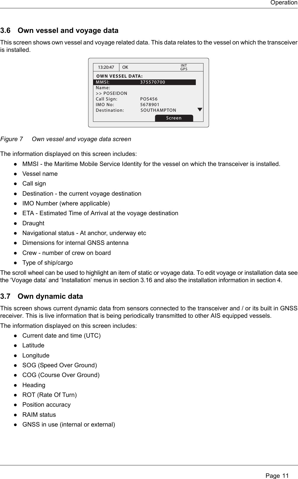
![Installation Page 47To enter the GNSS antenna locations go back to the main menu and select the ‘Dimensions’ then ‘Internal’ or 'External’ option as appropriate. Dimensions for both the internal and external GNSS antennas must be entered if an external GNSS is connected to the AIS transceiver. The antenna dimensions should be entered in metres according to the diagram provided in Figure 52. Figure 52 Vessel dimensions measurement4.5.3 Configure voyage related dataThe transceiver must be configured with information about its voyage prior to operation. The following information is required:●Nav Status - Navigational status selected from the list below:○0 - Under way using engine.○1 - At anchor.○2 - Not under command.○3 - Restricted manoeuvrability.○4 - Constrained by her draught.○5 - Moored.○6 - Aground.○7 - Engaged in fishing.○8 - Under way sailing.○9 to 14 - reserved for future use.○15 - not defined (default setting).●Destination - Ships next destination port (limited to 20 characters).●ETA - Estimated time / date of arrival at destination (using UTC time).●Draught - Maximum present static draught to the nearest 1/10th of a metre.●Ship and cargo type - a two digit code selected using Table 8. Where the second digit is represented by [n] the appropriate code for the second digit should be selected from Table 9. ●Crew - Number of crew on board (optional).To enter the vessel identification information press the ‘Menu’ key and select the ‘Voyage Data’ option. The vessels Nav. status, Destination, ETA, Draught, Type and number of crew can then be entered.Ref AAntennaRef A + Ref B = Length in metres Ref C + Ref D = Beam in metresRef BStern BowRef CRef D](https://usermanual.wiki/SRT-Marine-Systems-plc/405-0002.User-manual/User-Guide-1366566-Page-51.png)
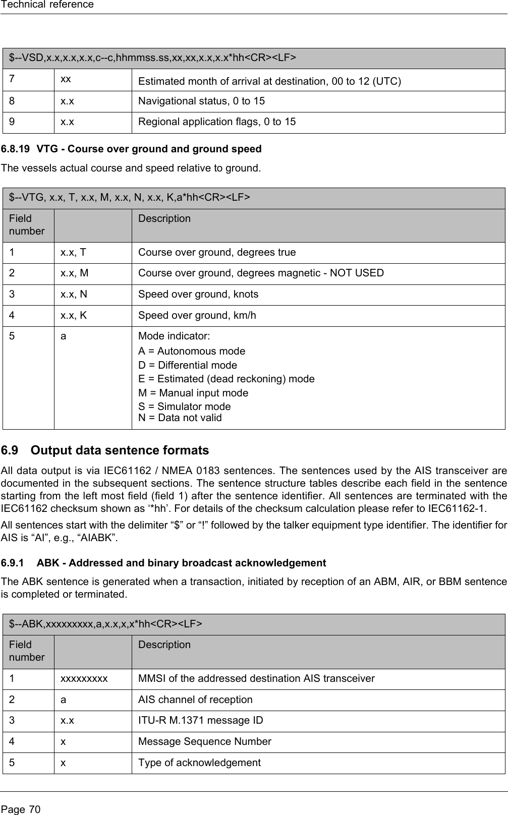
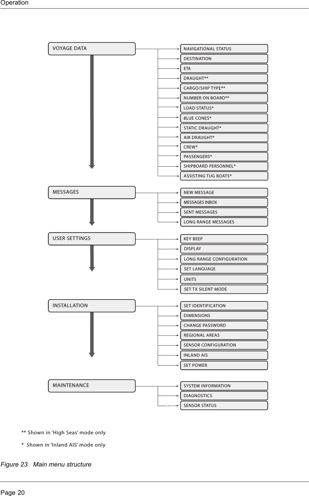
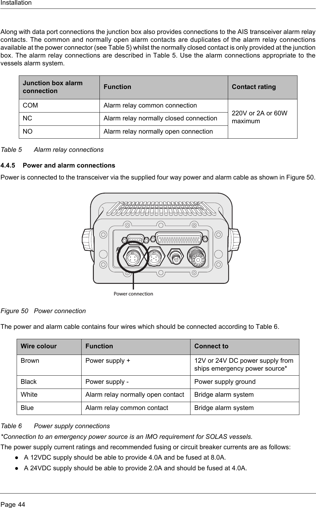
![InstallationPage 48Table 8 Vessel types and their corresponding vessel type codesTable 9 Type codes for vessels carrying cargoVessel type Type codeReserved (do not use) 1[n]Wing in ground craft 2[n]Fishing 30Towin g 31Towing and length of tow exceeds 200m or breadth exceeds 25m 32Engaged in dredging or underwater operations 33Engaged in diving operations 34Engaged in military operations 35Sailing 36Pleasure craft 37(HSC) High speed craft 4[n]Pilot vessel 50Search and rescue vessel 51Tug 52Port tender 53Vessel with anti-pollution facilities 54Law enforcement vessel 55Spare - for local use 56Spare - for local use 57Medical transports (under the 1949 Geneva conventions and additional protocols) 58Ships according to RR Resolution No. 18 (Mob-83) - Relating to the Procedure for Identifying and Announcing the Position of Ships and Aircraft of States Not Parties to an Armed Conflict59Passenger ship 6[n]Cargo ship 7[n]Tanker 8[n]Other type of ship 9[n]Cargo type Second digit(where not predefined)All ships of this type 0Carrying DG, HS, or MP, IMO hazard or pollutant category A 1Carrying DG, HS, or MP, IMO hazard or pollutant category B 2Carrying DG, HS, or MP, IMO hazard or pollutant category C 3Carrying DG, HS, or MP, IMO hazard or pollutant category D 4Reserved (do not use) 5Reserved (do not use) 6Reserved (do not use) 7Reserved (do not use) 8No additional information 9](https://usermanual.wiki/SRT-Marine-Systems-plc/405-0002.User-manual/User-Guide-1366566-Page-52.png)