SRT Marine Systems plc 405-0002 PROTEC-W AIS Class A CS User Manual L3 custom posiedon manual English
Software Radio Technology plc PROTEC-W AIS Class A CS L3 custom posiedon manual English
Contents
- 1. Installation and users guide
- 2. User manual
User manual

PROTEC-W
Automatic Identification System / Inland AIS
Installation and Operation Manual
Thank you for purchasing this AIS Class A transceiver / Inland AIS.
This product has been engineered to offer you the highest level of performance and
durability and we hope that it will provide many years of reliable service. We constantly
strive to achieve the highest possible quality standards, should you encounter any
problems with this product, please contact your dealer who will be pleased to offer any
assistance you require.

Page 1
Contents
1 Notices..............................................................................................3
1.1 Safety warnings ............................................................................................................................ 3
1.2 General notices............................................................................................................................. 3
1.3 Revision information ..................................................................................................................... 4
2 Introduction......................................................................................5
2.1 About AIS...................................................................................................................................... 5
2.2 Static and dynamic vessel data .................................................................................................... 6
2.3 AIS operation licensing ................................................................................................................. 6
3 Operation..........................................................................................7
3.1 Display and controls...................................................................................................................... 7
3.2 Turning the transceiver on ............................................................................................................ 8
3.3 Display layout................................................................................................................................ 8
3.4 Main operating screens................................................................................................................. 9
3.5 Target list .................................................................................................................................... 10
3.6 Own vessel and voyage data...................................................................................................... 11
3.7 Own dynamic data ...................................................................................................................... 11
3.8 Received messages.................................................................................................................... 12
3.9 Alarms screen............................................................................................................................. 12
3.10 Target plot screen ....................................................................................................................... 13
3.11 Working with AIS text and Safety Related Messages (SRMs).................................................... 14
3.12 Handling alarms .......................................................................................................................... 15
3.13 Entering text................................................................................................................................ 16
3.14 Long range messages ................................................................................................................ 17
3.15 Passwords and security.............................................................................................................. 19
3.16 The configuration menu .............................................................................................................. 19
3.17 Tanker mode............................................................................................................................... 25
3.18 Silent mode................................................................................................................................. 25
3.19 Inland AIS ................................................................................................................................... 27
4 Installation......................................................................................31
4.1 What’s in the box? ...................................................................................................................... 32
4.2 Preparing for installation ............................................................................................................. 33
4.3 Installation procedures................................................................................................................ 33
4.4 Connecting the equipment.......................................................................................................... 39
4.5 Configuring the Protec-W transceiver .........................................................................................46
4.6 Changing the password .............................................................................................................. 49
4.7 Confirming correct operation....................................................................................................... 49
4.8 Regional area settings ................................................................................................................ 49
4.9 Manually setting the transmitter power .......................................................................................50
4.10 Silent mode switch connection.................................................................................................... 51
4.11 Inland AIS ................................................................................................................................... 52
5 Technical Specifications...............................................................55
5.1 Applicable equipment standards................................................................................................. 55

Page 2
5.2 Physical ...................................................................................................................................... 55
5.3 Environmental ............................................................................................................................ 55
5.4 Electrical .................................................................................................................................... 55
5.5 Display and user interface ......................................................................................................... 56
5.6 Internal GPS .............................................................................................................................. 56
5.7 TDMA transmitter ....................................................................................................................... 56
5.8 TDMA receivers .......................................................................................................................... 56
5.9 DSC receiver............................................................................................................................... 57
5.10 RF connections........................................................................................................................... 57
5.11 Data interfaces............................................................................................................................ 57
5.12 Power and data connector information ....................................................................................... 58
6 Technical reference.......................................................................59
6.1 Interface sentences..................................................................................................................... 59
6.2 Transmission intervals ................................................................................................................ 60
6.3 Sensor data input port................................................................................................................. 60
6.4 Bi-directional data ports .............................................................................................................. 61
6.5 Output drive capability of bi-directional ports ..............................................................................61
6.6 DGPS port................................................................................................................................... 61
6.7 RS232 port.................................................................................................................................. 61
6.8 Input data sentence formats ....................................................................................................... 61
6.9 Output data sentence formats..................................................................................................... 70
7 Drawings ........................................................................................74
7.1 AIS transceiver overall dimensions............................................................................................. 74
7.2 Junction box overall dimensions ................................................................................................. 74
7.3 Dash mount bracket fixing holes (drill drawing) (not to scale) .................................................... 75
7.4 GPS antenna drawing (not to scale)...........................................................................................75
8 Annex A - ERI Ship types..............................................................76
9 Installation record .........................................................................79
10 Warranty .........................................................................................83

Page 1
List of Figures
Figure 1 The AIS network ................................................................................................................. 5
Figure 2 Transceiver front panel ....................................................................................................... 7
Figure 3 Display layout ..................................................................................................................... 8
Figure 4 Selection of main operating screen .................................................................................... 9
Figure 5 Target list screen and vessel details view ........................................................................ 10
Figure 6 Vessel type icons.............................................................................................................. 10
Figure 7 Own vessel and voyage data screen................................................................................ 11
Figure 8 Own dynamic data screen ................................................................................................ 12
Figure 9 Received messages screen.............................................................................................. 12
Figure 10 Message details view........................................................................................................ 12
Figure 11 Alarms screen................................................................................................................... 13
Figure 12 Alarm details view............................................................................................................. 13
Figure 13 Target plot screen............................................................................................................. 13
Figure 14 Target plot symbols .......................................................................................................... 14
Figure 15 Safety Related Message notification ................................................................................ 14
Figure 16 Message composition ....................................................................................................... 15
Figure 17 Alarm notification screen .................................................................................................. 16
Figure 18 Text entry.......................................................................................................................... 17
Figure 19 Long range interrogation notification; automatic response mode enabled ....................... 18
Figure 20 Long range interrogation notification; manual response mode enabled ........................... 18
Figure 21 Long range message list and details views ...................................................................... 18
Figure 22 Password entry screen ..................................................................................................... 19
Figure 23 Main menu structure......................................................................................................... 20
Figure 24 Main menu screen ............................................................................................................ 21
Figure 25 The voyage data menu ..................................................................................................... 21
Figure 26 The messages menu ........................................................................................................ 22
Figure 27 The user settings menu .................................................................................................... 22
Figure 28 The installation menu........................................................................................................ 23
Figure 29 The maintenance menu .................................................................................................... 24
Figure 30 Diagnostics menu ............................................................................................................. 24
Figure 31 Tanker mode entry acknowledgement screen.................................................................. 25
Figure 32 Tanker mode exit screen when speed exceeds 3 knots................................................... 25
Figure 33 Silent mode entry confirmation screen ............................................................................. 26
Figure 34 New message composition screen................................................................................... 29
Figure 35 Typical AIS transceiver connection................................................................................... 31
Figure 36 What’s in the box .............................................................................................................. 32
Figure 37 AIS transceiver dimensions .............................................................................................. 34
Figure 38 Mounting the AIS transceiver............................................................................................ 34
Figure 39 Panel mounting the AIS transceiver ................................................................................. 35
Figure 40 Junction box dimensions .................................................................................................. 36
Figure 41 Mounting the junction box................................................................................................. 36
Figure 42 GPS antenna location....................................................................................................... 37
Figure 43 GPS antenna connection.................................................................................................. 37
Figure 44 VHF antenna installation................................................................................................... 38
Figure 45 VHF antenna connection .................................................................................................. 39
Figure 46 Connecting the junction box to the transceiver................................................................. 39
Figure 47 Junction box connections ................................................................................................. 41
Figure 48 Example connection to external display equipment.......................................................... 43
Figure 49 Line termination options.................................................................................................... 43
Figure 50 Power connection ............................................................................................................. 44
Figure 51 PC data (RS232) connection............................................................................................ 45
Figure 52 Vessel dimensions measurement..................................................................................... 47
Figure 53 Regional areas list screen ................................................................................................ 49
Figure 54 Regional area editing screen ............................................................................................ 50
Figure 55 Regional area settings confirmation screen...................................................................... 50

Page 2
Figure 56 Silent mode switch connection ......................................................................................... 51
Figure 57 Blue sign switch connection.............................................................................................. 54
Figure 58 Input port schematic ......................................................................................................... 60
Figure 59 Data output port schematic............................................................................................... 61
Notices
Page 3
1 Notices
When reading this manual please pay particular attention to warnings marked with the
warning triangle symbol shown on the left. These are important messages for safety,
installation and usage of the transceiver.
1.1 Safety warnings
1.2 General notices
1.2.1 Position source
All marine Automatic Identification System (AIS) transceivers utilise a satellite based location system such as
the Global Positioning Satellite (GPS) network.
The general term for satellite based location systems is Global Navigation Satellite System or GNSS. This
manual refers to either GNSS or GPS depending on context.
1.2.2 Compass safe distance
The compass safe distance of this transceiver is 0.3m or greater for a 0.3° deviation.
1.2.3 Product category
This product is categorised as ‘protected’ in accordance with the definitions provided in IEC 60945.
The accuracy of a GPS position fix is variable and affected by factors such as the antenna
positioning, how many satellites are used to determine a position and for how long satellite
information has been received.
This equipment must be installed in accordance with the instructions provided in this manual. Failure
to do so will seriously affect its performance and reliability. It is strongly recommended that a trained
technician installs and configures this product.
This equipment is intended as an aid to navigation and is not a replacement for proper navigational
judgement. Information provided by the equipment must not be relied upon as accurate. User
decisions based upon information provided by the equipment are done so entirely at the users own
risk.
Do not install this equipment in a flammable atmosphere such as in an engine room or near to fuel
tanks.
Do not attempt to service this equipment as doing so may cause fire, electric shock or malfunction and
will invalidate the warranty. If any malfunctions are detected contact your supplier or service agent.
Do not install the transceiver where rain or water may leak onto the equipment. This product has been
designed for installation and use in an environment protected from moisture.
NOT ALL SHIPS CARRY AIS. The Officer of the Watch (OOW) should always be aware that other
ships and, in particular, leisure craft, fishing vessels and warships may not be fitted with AIS. Any AIS
equipment fitted on other ships as a mandatory carriage requirement may also be off based on the
Master’s professional judgement.
It is recommended that this product is not installed in direct sunlight or under a windshield where it can
be subjected to excessive solar heating.

Notices
Page 4
1.2.4 Disposal of the transceiver and packaging
Please dispose of this AIS transceiver in accordance with the European WEEE Directive or with the applicable
local regulations for disposal of electrical equipment. Every effort has been made to ensure the packaging for
the transceiver is recyclable. Please dispose of the packaging in an environmentally friendly manner.
1.2.5 Accuracy of this manual
This manual is intended as a guide to the installation, setup and use of this product. Every effort has been made
to ensure the accuracy of this manual, however due to continuous product development this manual may not
be accurate in all respects, therefore no guarantee is offered. If you are in any doubt about any aspect of this
product, please contact your dealer.
Manual version number: 1.0
1.2.6 Marine Equipment Directive
The Protec-W transceiver complies with international standards and is type approved in accordance with the
European Marine Equipment Directive. The EU Declaration of Conformity is provided at the rear of this manual
and lists the relevant approval standards.
1.3 Revision information
This manual applies to the following transceiver hardware and software versions:
●Transceiver software version 030201.05.03.00
●Display software version 030401.02.04.00
●Hardware version 4.0
Notified Body No: 0168
Year: 2010
Introduction
Page 5
2Introduction
2.1 About AIS
The marine Automatic Identification System (AIS) is a location and vessel information reporting system. It
allows vessels equipped with AIS to automatically and dynamically share and regularly update their position,
speed, course and other information such as vessel identity with similarly equipped vessels. Position is derived
from the Global Positioning System (GPS) and communication between vessels is by Very High Frequency
(VHF) digital transmissions.
There are a number of types of AIS device as follows:
●Class A transceivers. These are designed to be fitted to commercial vessels such as cargo ships
and large passenger vessels. Class A transceivers transmit at a higher VHF signal power than class
B transceivers and therefore can be received by more distant vessels, and also transmit more
frequently. Class A transceivers are mandatory on all vessels over 300 gross tonnes on international
voyages and certain types of passenger vessels under the SOLAS mandate.
●Inland AIS stations. Similar to class A transceivers with additional features for use on Inland
waterways.
●Class B transceivers. Similar to Class A transceivers in many ways, but are normally lower cost due
to the less stringent performance requirements. Class B transceivers transmit at a lower power and at
a lower reporting rate than Class A transceivers.
●AIS base stations. AIS base stations are used by Vessel Traffic Systems to monitor and control the
transmissions of AIS transceivers.
●Aids to Navigation (AtoN) transceivers. AtoNs are transceivers mounted on buoys or other
hazards to shipping which transmit details of their location to the surrounding vessels.
●AIS receivers. AIS receivers receive transmissions from Class A transceivers, Class B transceivers,
AtoNs and AIS base stations but do not transmit any information about the vessel on which they are
installed.
The Protec-W transceiver is a combined Class A transceiver / Inland AIS.
Figure 1 The AIS network

Introduction
Page 6
2.2 Static and dynamic vessel data
Information transmitted by an AIS transceiver is in two categories: static and dynamic data.
The vessel's dynamic data which includes location, speed over ground (SOG) and course over ground (COG)
is calculated automatically using the internal GPS receiver.
Static data is information about the vessel which must be programmed into the AIS transceiver. This includes:
●Maritime Mobile Service Identity (MMSI)
●Vessel name
●Vessel call sign (if available)
●Vessel type
●Vessel dimensions
2.3 AIS operation licensing
In most countries the operation of an AIS transceiver is included under the vessel's marine VHF licence
provisions. The vessel on to which the AIS transceiver is to be installed must therefore possess a current VHF
radiotelephone licence which lists the AIS system, vessel Call Sign and MMSI number. Please contact the
relevant authority in your country for further information regarding ship’s radio licensing requirements.

Operation
Page 7
3Operation
This section assumes that the Protec-W transceiver has been installed in accordance with the instructions
provided in the Installation section of this manual.
Please read the warning notices at the front of this manual before operating the AIS transceiver.
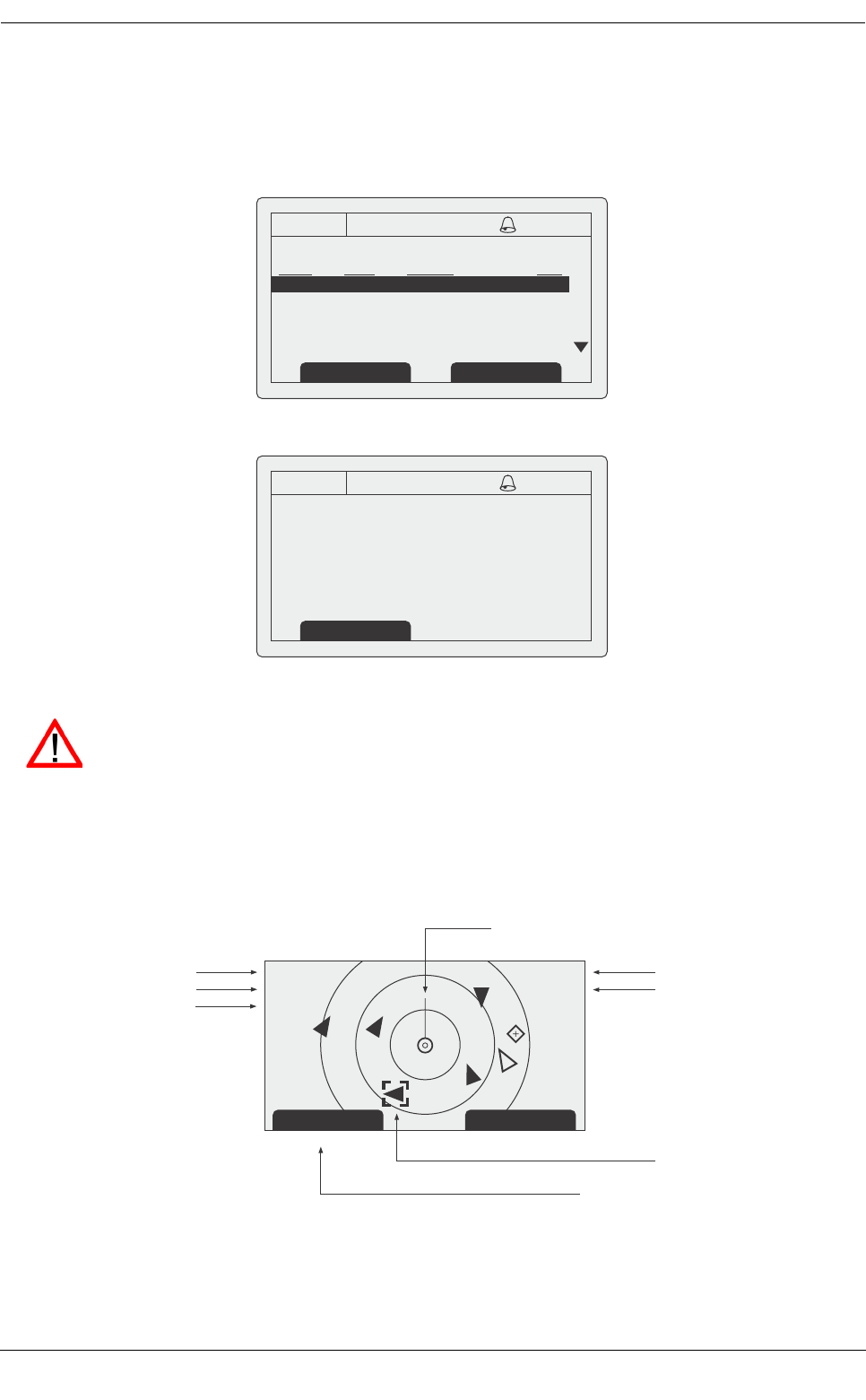
3.1 Display and controls
Figure 2 Transceiver front panel
The front panel of the transceiver is shown in Figure 2 with each control marked.
Menu key
This key provides access to the transceiver set up and configuration menu from any operating screen.
Back key
This key cancels the current operation, moves to the previous menu level or acts as a backspace key
depending on the operation being carried out.
Scroll wheel
The scroll wheel is used to select information presented on the display, select menu items and edit text and
numeric information shown on the screen. The scroll wheel can also be pressed to confirm data entry or select
information presented on the display.
Right and left function keys
The function of these keys is shown in the display area directly above each key. The function depends on the
operation being carried out.
Brightness / silent mode control
Turning the brightness control left or right will adjust the display and keypad backlight level. Rotating
counter-clockwise will reduce the brightness. Pressing the control knob allows selection of ‘Silent mode’ (see
3.18).
Status light
The status light indicates the operational status of the AIS transceiver and may be illuminated either green or
red. Whilst the light is green the AIS is operating normally. If the indicator is red then the AIS is unable to
operate normally due to a system or configuration error. See section 3.9 for a description of error and alarm
conditions.
BACK
Display
Sounder
Menu key
Back key
Pilot plug (behind protective cover)
Brightness control
(and ‘Silent mode’ control)
Scroll wheel
Status Light
Right function key
Left function key
MENU
Operation
Page 8
Sounder
The Sounder provides an audible ‘beep’ when a key is pressed. Key beeps can be activated or deactivated via
the User Settings menu (see section 3.16).
Pilot Plug
The Pilot Plug provides an AIS connection for pilots using the IMO standard Pilot Plug connector.
Display
The display shows essential AIS operating information and allows for configuration of the transceiver. It is
recommended that the transceiver is connected to a compatible Radar or Electronic Chart Display System
(ECDIS) for monitoring of AIS vessels during navigation.
3.2 Turning the transceiver on
The Protec-W transceiver does not have a power switch and is designed to be permanently powered. When
power is first applied the display will show a splash screen for approximately 5 seconds before the main
operating screen is shown.
3.3 Display layout
The display layout is shown in Figure 3. All operating screens show the time, status bar, scroll indicators and
relevant function keys. The time displayed is UTC time.
When no UTC time is available from the internal GNSS module the time display will show --:--:-- in place of the
time of day.
Figure 3 Display layout
3.3.1 Status bar icons
The status bar shows the current transceiver status using icons. The meaning of each icon is described in Table 1.
Icon Description
OK The transceiver is operating normally.
Tx Shown for one second following each transmission.
Tx Shown when the transmitter is disabled
Rx Shown for one second following each received message.
HH:MM:SS
Select Screen
Main display area
UTC time
Left function key
Scroll indicators
Status bar
Right function key
Operation
Page 9
Table 1 Status Icons
3.4 Main operating screens
In normal operation the display shows one of six main operating screens. The next screen can be selected at
any time by pressing the ‘Screen’ function key as shown in Figure 4. The following subsections describe each
of the operating screens in more detail.
Figure 4 Selection of main operating screen
INT
GPS
Shown when the internal GPS receiver has a valid position
fix.
EXT
GPS
Shown when a connected external GPS receiver has a valid
position fix.
INT
DGPS
Shown when the internal GPS receiver has a valid differential
position fix.
EXT
DGPS
Shown when a connected external GPS receiver has a valid
differential position fix.
NO
GPS
Shown when there is no valid internal or external position fix.
Shown when unread AIS safety related text messages are
available.
Shown flashing when an alarm is active, shown constantly
when an alarm is active, but acknowledged.
1W Shown when the transmitter is set to 1W mode
IL Shown when the AIS transceiver is operating in ‘Inland
Waterways’ mode.
Icon Description
Target list Own vessel &
voyage data
Own dynamic
data
Target plot Alarms Received
messages
Operation
Page 10
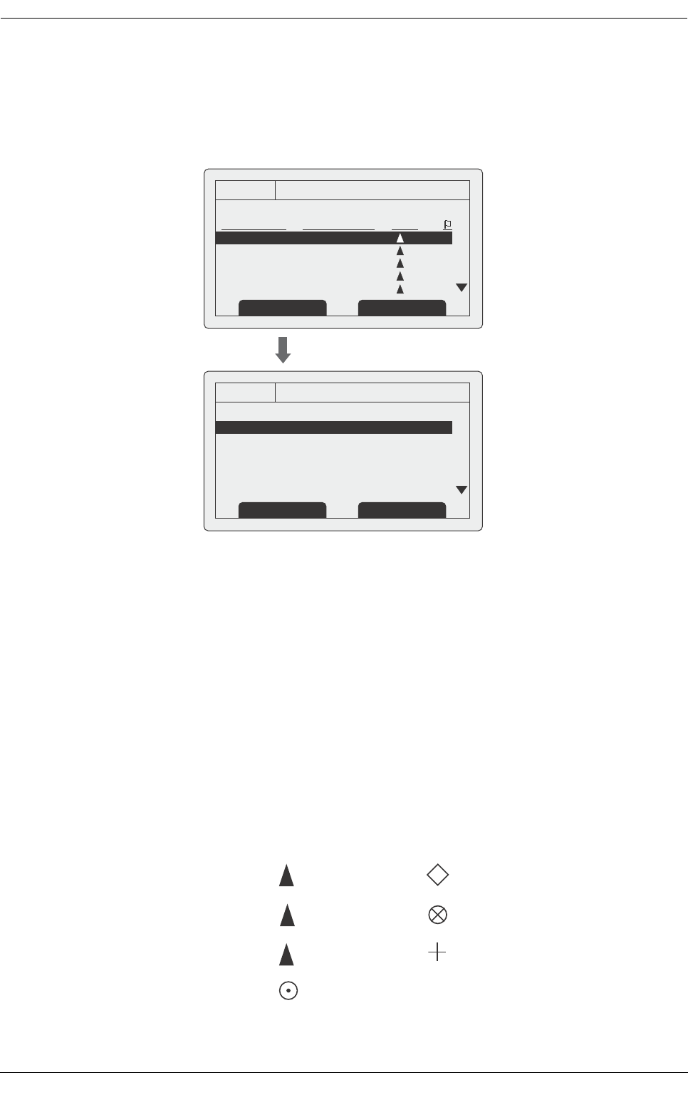
3.5 Target list
The target list screen is shown by default after power up. This screen shows the name (or MMSI), range (in
nautical miles) and bearing (in degrees) of other AIS equipped vessels. The nearest vessel is shown at the top
of the list. Only the 200 nearest vessels are shown in the target list, more distant vessels may be viewed if an
AIS enabled external display, RADAR or ECDIS is connected to the transceiver.
Figure 5 Target list screen and vessel details view
The columns shown on the target screen are:
●Name or MMSI number of the target vessel
●Range and bearing to the target vessel. Range can be shown in nautical miles (nm) or kilometers
(km) depending on user settings (see section 3.16). The bearing to a target vessel is shown in
degrees.
●Type of vessel. This column shows the type of vessel using the icons in Figure 6
●Blue sign status (only shown when operating in Inland AIS mode - see 3.19), Icons in this column
indicate if a target vessel has it’s blue sign shown, not shown or not available.
When the target list screen is displayed the scroll wheel can be used to move through the list. Full details of
the highlighted vessel can be shown by pressing the ‘Select’ function key, or pushing the scroll wheel. To return
to the target list from the vessel details screen press the ‘Back’ key. Whilst the vessel details screen is displayed
it is possible to view details of the next and previous vessels in the vessel list using the left and right function
keys without returning to the target list screen.
Figure 6 Vessel type icons
13:20:47
TARGET LIST: (30 TARGETS)
NAME/MMSI RNG(NM)/BRG TYPE
MARY ROSE
REGENT
ANNE GALL...
235789543
45672355
OK GPS
INT
ScreenSelect
13:20:47
VESSEL DETAILS:
Station type: Class A
MMSI: 235687901
Name:
>> MARY ROSE
Call Sign: MYR7A
IMO No: 4325640
OK GPS
INT
Prev. vessel Next vessel
001.5 / 254.0
003.0 / 013.0
012.5 / 135.5
015.0 / 003.0
030.0 / 087.5
A
A
A
A
A
A
B
I
Class A vessel
Class B vessel
Inland vessel
Base station
AtoN
SAR aircraft
AIS SART

Operation
Page 11
3.6 Own vessel and voyage data
This screen shows own vessel and voyage related data. This data relates to the vessel on which the transceiver
is installed.
Figure 7 Own vessel and voyage data screen
The information displayed on this screen includes:
●MMSI - the Maritime Mobile Service Identity for the vessel on which the transceiver is installed.
●Vessel name
●Call sign
●Destination - the current voyage destination
●IMO Number (where applicable)
●ETA - Estimated Time of Arrival at the voyage destination
●Draught
●Navigational status - At anchor, underway etc
●Dimensions for internal GNSS antenna
●Crew - number of crew on board
●Type of ship/cargo
The scroll wheel can be used to highlight an item of static or voyage data. To edit voyage or installation data see
the ‘Voyage data’ and ‘Installation’ menus in section 3.16 and also the installation information in section 4.
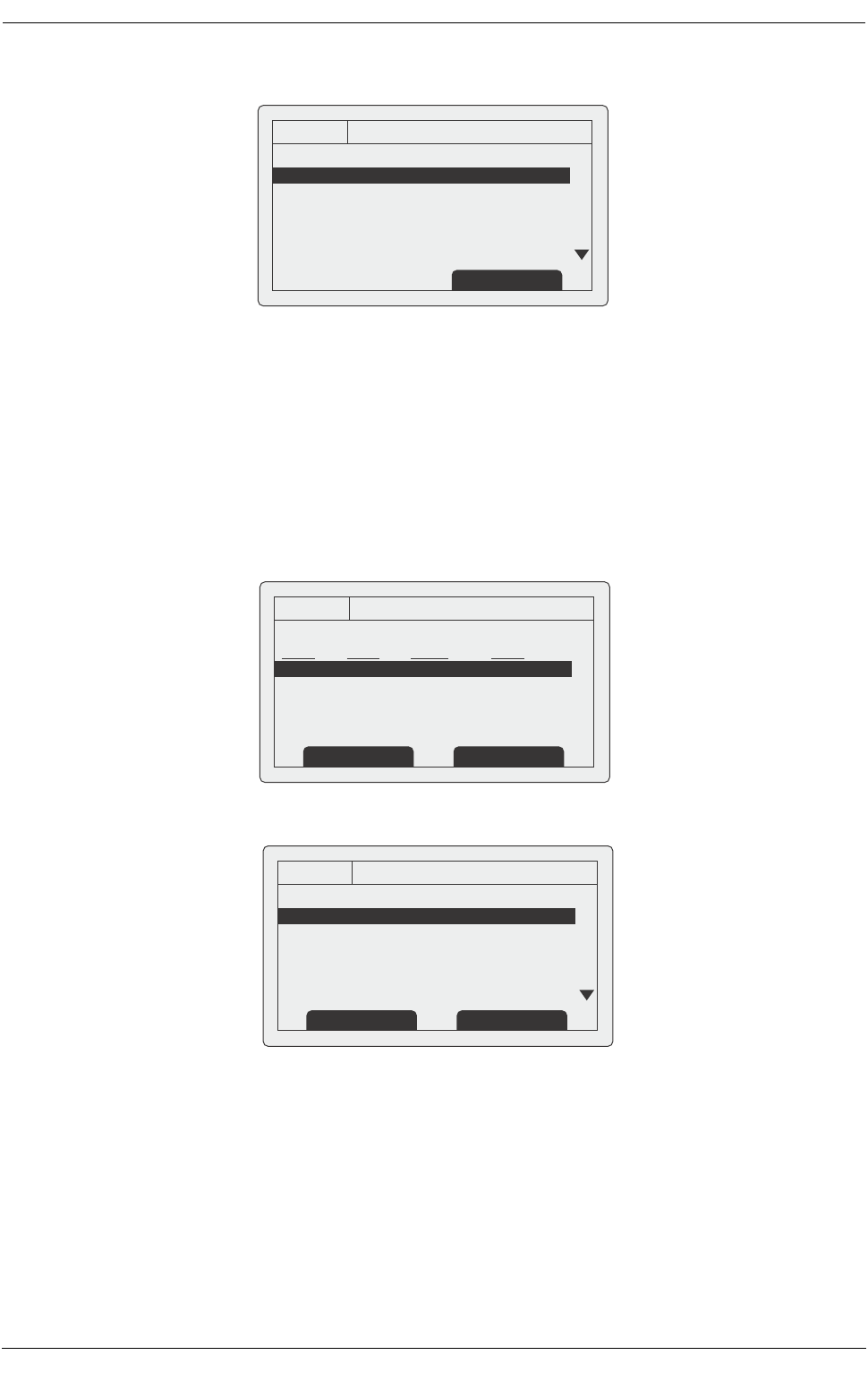
3.7 Own dynamic data
This screen shows current dynamic data from sensors connected to the transceiver and / or its built in GNSS
receiver. This is live information that is being periodically transmitted to other AIS equipped vessels.
The information displayed on this screen includes:
●Current date and time (UTC)
●Latitude
●Longitude
●SOG (Speed Over Ground)
●COG (Course Over Ground)
●Heading
●ROT (Rate Of Turn)
●Position accuracy
●RAIM status
●GNSS in use (internal or external)
13:20:47
OWN VESSEL DATA:
MMSI: 375570700
Name:
>> POSEIDON
Call Sign: POS456
IMO No: 5678901
Destination: SOUTHAMPTON
OK GPS
INT
Screen
Operation
Page 12
Figure 8 Own dynamic data screen
3.8 Received messages
This screen shows AIS text and Safety Related Messages (SRM) received from other AIS stations. The most
recently received message is shown at the top of the list. The date and time of reception, name or MMSI of the
sending station and type of message (text or SRM) are shown in the message list. To view the message content
select the required message using the scroll wheel, then either press the scroll wheel or the “View” function key.
The received messages screen is shown in Figure 9 and the message details screen in Figure 10. When
unread messages are available to view the message icon is shown in the status bar as described in section
3.3.1.
Figure 9 Received messages screen
Figure 10 Message details view
3.9 Alarms screen
This screen shows the status of AIS system alarms. If an active and not yet acknowledged alarm condition
exists the alarm icon in the status bar will flash. If an alarm condition occurs whilst not in the menu system an
acknowledgement screen will be shown immediately, this is described in section 3.12. If an alarm condition
occurs whilst editing a field in the menu system the alarm bell symbol flashes in the status bar.
13:20:47
OWN DYNAMIC DATA:
Date: 06/01/2010
Time: 13:24:04
Lat: 51°16.7904N
Long: 002°27.9458
SOG: 010.0kts
COG: 134.0°
OK GPS
INT
Screen
13:20:47
RECEIVED MESSAGES:
DATE TIME FROM TYPE
29/01 10:00 MARY R... B R Safety
29/01 09:55 556444321 AD Safety
28/01 21:45 REGENT B R Binary
OK GPS
INT
View Screen
13:20:47
MESSAGE DETAILS:
Type: Broadcast SRM
MMSI: 235687901
NAME:
>>MARY ROSE
Channel: A
Date: 29/01/2010
OK GPS
INT
Back Reply
Operation
Page 13
The alarms screen shows the date and time of activation along with a brief description of any active alarm and
it’s acknowledge state — see Figure 11. Alarms that are active but not acknowledged by the operator have ‘No’
in the ‘Ack’ column. Once an alarm is acknowledged by the operator ‘Yes’ is displayed in the ‘Ack’ column. An
individual alarm can be selected from the list using the scroll wheel and it’s details viewed by either pressing
the scroll wheel or the “View” function key. The alarm details view is shown in Figure 12.
Figure 11 Alarms screen
Figure 12 Alarm details view
3.10 Target plot screen
The target plot screen shows the location of other AIS equipped vessels and shore stations relative to your own
vessel. The target plot screen provides a basic overview of AIS targets and should not be regarded as a
substitute for display of AIS information on a dedicated electronic chart display system (ECDIS).
Figure 13 Target plot screen
13:20:47
ALARMS LIST:
DATE TIME ALARM ACK
25/11 16:13 No valid ROT... Yes
25/11 16:11 Heading lost... Yes
25/11 16:11 External EPFS... Yes
OK GPS
INT
View Screen
13:20:47
ALARM DETAILS:
ALARM: No valid ROT information
ID: 35
DATE: 25/11/2010
TIME: 16:13:30
ACK: Yes
OK GPS
INT
Exit
While alarm conditions are active and un-acknowledged, any connected external alarm system
will remain activated.
Range Screen
Name of selected target MMSI of selected target
Heading line (points up to signify heading up)
Selected target
[HDG UP] 27 Tgts
10nm
MARY ROSE 235687901
Number of targets on display
Range selection key
heading up mode
Range selected
Operation
Page 14
The plot range can be adjusted by pressing the ‘Range’ function key which cycles through the ranges 48, 24,
12, 6, 3, 1 and 0.5nm. The range relates to radius of the outer range ring shown on the screen.
Individual targets can be selected using the scroll wheel. When selected a square outline will appear around
the target, pressing the scroll wheel will display full vessel details. To return to the target plot screen from the
vessel details screen press the back key.
Different symbols are displayed for an AIS target depending on the type of target and its status, these are
shown in Figure 14. The own vessel symbol is always shown at the centre of the plot.
Figure 14 Target plot symbols
3.11 Working with AIS text and Safety Related Messages (SRMs)
AIS text messages and Safety Related Messages (SRMs) can be received from other AIS equipped vessels
and also sent to specific vessels (addressed messages) or sent to all vessels in range (broadcast messages).
3.11.1 Receiving AIS text and Safety Related Messages
Reception of an AIS text message is indicated by the presence of the message icon in the status bar. This icon
is shown whenever there are unread AIS text messages. Messages can be reviewed and replied to via the
messages screen; see section 3.8.
When a Safety Related Message is received the user will be notified immediately with a screen showing the
message. Standard text messages are not displayed on receipt, however the message icon will be displayed
on the status bar.
Figure 15 Safety Related Message notification
3.11.2 Sending AIS Text and Safety Related Messages
To compose a new text or Safety Related Message (SRM) press the ‘Menu’ key then select the ‘MESSAGES’
sub menu followed by the ‘SEND A MESSAGE’ option. The new message screen is shown in Figure 16. To
send a message complete the following steps:
1. Using the scroll wheel highlight the ‘TYPE’ field and select the type of message you wish to send. The
available options are ‘Broadcast text’, ‘Addressed Text’, ‘Broadcast SRM’ and ‘Addressed SRM’. Ad-
ditional message types are available when operating in Inland AIS mode, see section 3.19.5. Click the
scroll wheel to confirm the message type.
2. For addressed message types only select the ‘TO’ field and press the scroll wheel. Enter the MMSI of
the vessel the message should be sent to using the scroll wheel. See section 3.13 for instructions on
using the scroll wheel to enter data.
Lost target (vessel)
Target (vessel)
Own vessel
AtoN
Base station
SART
13:20:47
SAFETY RELATED MESSAGE:
Type: Broadcast SRM
MMSI: 235687901
NAME:
>>MARY ROSE
Channel: A
Date: 29/01/2010
OK GPS
INT
Back Reply
Operation
Page 15
3. Select the ‘MESSAGE’ field and enter your message. Note that the length of a message is limited as
follows:
○Addressed SRM 156 characters
○Broadcast SRM 161 characters
○Addressed text 151 characters
○Broadcast text 156 characters
4. Press the ‘Send’ function key to transmit the message.
When an addressed message is sent the addressee will return an acknowledgement on receipt of the
message. If this acknowledgement is not received a warning will be displayed.
Figure 16 Message composition
Warning: Class B transceivers are permitted to receive broadcast Safety Related Messages and
broadcast text messages, however this function is not mandatory. Class B transceivers are not able
to receive addressed Safety Related or text messages. There is therefore no guarantee that text
messages or SRMs sent to a Class B transceiver will be received.
3.12 Handling alarms
The Protec-W transceiver performs self checking functions continuously. If a self check fails an alarm will occur.
Possible alarm conditions are listed in Table 2.
Alarm condition Description
Transmitter malfunction This alarm can occur if there is a fault with the transmitter or if
the antenna VSWR exceeds allowable limits. The alarm will be
cleared if the transmitter recovers normal operation or the VSWR
measurement returns to an allowable value. If this alarm condi-
tion persists contact your dealer or installer.
Antenna VSWR exceeds limit This alarm condition can occur if the VSWR (Voltage Standing
Wave Ratio) of the AIS antenna exceeds pre-defined limits. This
alarm is cleared if the VSWR returns to an allowable value. If this
alarm condition persists contact your dealer or installer.
Receiver channel x malfunc-
tion
This alarm occurs should the receiver hardware malfunction. The
receiver is identified by the value of x. If the receiver returns to
normal operation this alarm will be cleared. If this alarm condition
persists contact your dealer or installer.
External EPFS lost This alarm occurs if the position from the external Electronic
Position Fixing System (i.e. GNSS) is invalid or lost.
No sensor position in use This alarm occurs if the transceiver has no valid position informa-
tion from any connected sensor.
13:20:47
NEW MESSAGE:
Type: Broadcast SRM
MMSI: Not required
Channel: Auto
Message:
OK GPS
INT
Back/Send Edit

Operation
Page 16
Table 2 Alarm conditions
A new alarm will be indicated by display of the alarm notification screen (see Figure 17). The alarm icon in the
status bar will flash whilst an alarm is active and not acknowledged by the user.
Figure 17 Alarm notification screen
From the alarm notification screen you have the option to immediately acknowledge the alarm by pressing the
‘ACK’ function key, or to view the active alarms list by pressing the ‘Goto List’ function key. Once an alarm is
acknowledged it will remain in the alarms list whilst the underlying alarm condition is active. The presence of
active but acknowledged alarm conditions is indicated by continuous display of the alarm icon in the status bar.
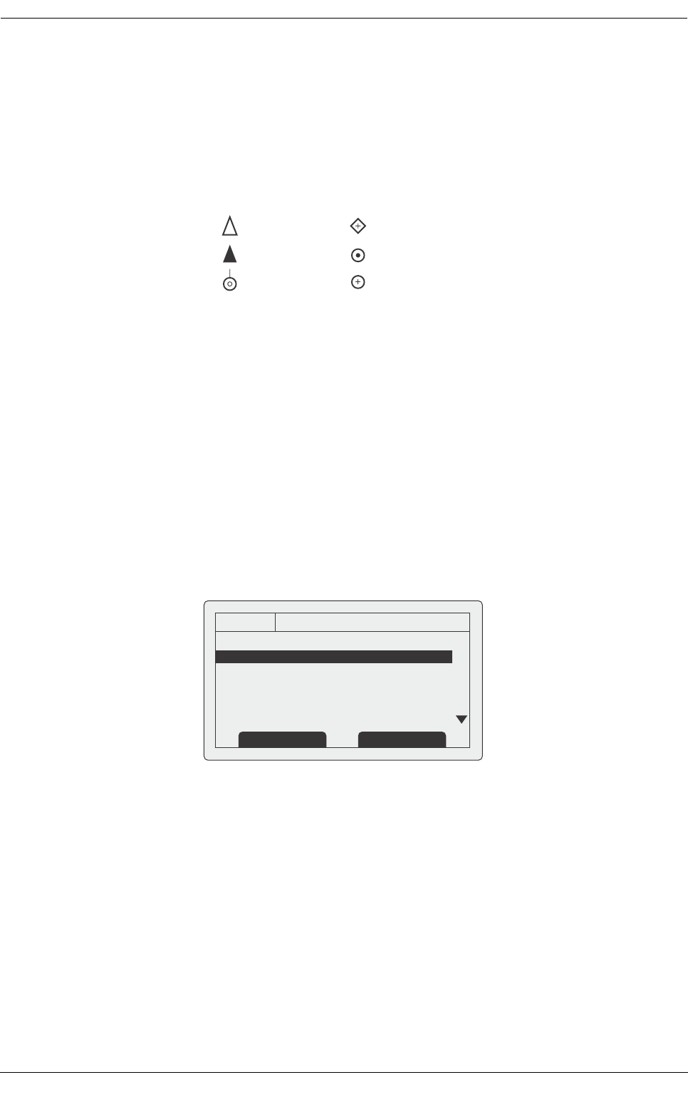
3.13 Entering text
The scroll wheel is used to enter text when updating settings or inputting new information. To enter or change
the text first select the field you wish to edit using the scroll wheel. The selected field is highlighted with white
text on a black background.
If the field is editable the ‘Edit’ function key will be shown. Either press this function key, or push the scroll wheel
to enter edit mode.
If text is already present in the field a solid block will now appear at the first character position, otherwise at the
first character position. Use the scroll wheel to move the block to the character position you wish to edit, then
press the scroll wheel. The selection will now flash, and rotating the scroll wheel will select the character for
this position. When the correct character is selected press the scroll wheel to fix the character and move to the
next character position. To ‘backspace’ (delete) a character simply press the ‘Back’ key. Figure 18 explains the
text entry process.
When you have completed entering text press the ‘Save’ function key to save the updated information.
No valid COG information This alarm occurs if the transceiver has no valid Course Over
Ground information from any connected sensor.
No valid SOG information This alarm occurs if the transceiver has no valid Speed Over
Ground information from any connected sensor.
Heading lost or invalid This alarm occurs if the transceiver has no valid heading infor-
mation from any connected sensor, or if the heading is unde-
fined.
No valid ROT information This alarm occurs if the transceiver has no Rate Of Turn informa-
tion from connected sensors or via internal calculation.
Alarm condition Description
13:20:47
ALARM NOTIFICATION:
ID ALARM
35: No valid ROT information
32: Heading lost/invalid
25: External EPFS lost
OK GPS
INT
Goto List Ack
Operation
Page 17
Figure 18 Text entry
3.14 Long range messages
If the Protec-W transceiver is connected to a long range communication system via the long range
communications port then long range interrogations may be received. These are requests for information from
a distant base station beyond normal AIS operation range.
The Protec-W transceiver can be configured to automatically respond to Long range (LR) interrogations, or you
can opt to respond to any interrogation manually. Automatic response is the default setting, see section 3.16
for details of the menu option used to change this setting. Note that in automatic mode all requested information
is returned if it is available.
When a Long range interrogation is received you will be alerted by a notification screen as shown in Figure 19
(when automatic response is enabled) or Figure 20 (when manual response is enabled).
In automatic response mode simply review and acknowledge the notification screen using the ‘Acknowledge’
function key to return to the previous operating screen. In manual response mode you should review the
request and select either the ‘Respond’ or ‘Decline’ function key as appropriate.
10:05:20
Own static and voyage data:
MMSI: 123456789
NAME: POSEIDON
DESTINATION: SOUTH
ETA: 06/06/10 1400Hrs
OK
GPS
INT
Edit Screen
12
10:05:23
Own static and voyage data:
MMSI: 123456789
NAME: POSEIDON
DESTINATION: SOUTH
ETA: 06/06/10 1400Hrs
OK
GPS
INT
Cancel Save
10:05:25
Own static and voyage data:
MMSI: 123456789
NAME: POSEIDON
DESTINATION: S OU T H
ETA: 06/06/10 1400Hrs
OK
GPS
INT
Cancel Save
34
56
Q
R
S
T
U
V
W
Operation
Page 18
Figure 19 Long range interrogation notification; automatic response mode enabled
Figure 20 Long range interrogation notification; manual response mode enabled
A list of received Long range interrogation messages is available at any time via the main menu ‘Messages’
sub menu. See section 3.16 for more details. The Long range message list shows the time and date of
reception of each message along with the sending base station’s MMSI. Full details on each Long range
interrogation in the list can be viewed by pressing the ‘View’ function key. The Long range message list and
details views are shown in Figure 21.
Figure 21 Long range message list and details views
13:20:47
Long range interrogation:
Date: 31/03/2010
Time: 13:15:39
MMSI: 001245368
OK GPS
INT
Name:
>> RES
Response automatically sent
Acknowledge
13:20:47
Long range interrogation:
Date: 31/03/2010
Time: 13:15:39
MMSI: 001245368
OK GPS
INT
Name:
>> RES
Set default responses
Respond
Decline
13:20:47
LONG RANGE MESSAGES:
DATE TIME FROM TYPE
08/01 15:52 002543887 Speed
08/01 15:30 002543887 Position
06/01 09:25 002564410 Course
OK GPS
INT
View
13:20:47
MESSAGE DETAILS:
Date: 08/01/10
Time: 07:35:39
MMSI: 002543887
Response automatically sent
Name:
>> RES
OK GPS
INT
Back Back
Operation
Page 19
3.15 Passwords and security
Certain important information stored within the transceiver can not be changed without knowledge of the
password. The protected information includes:
●MMSI number
●Name of vessel
●Call sign
●IMO number
●Channel management settings
●Vessel dimensions and GNSS antenna locations
●Type of ship
●Data interface configuration
When trying to edit any of the above information you will be prompted to enter the password.
The password entry screen is shown in Figure 22. Use the scroll wheel to select the required digit, then push
the scroll wheel to edit the value of that digit. Entered password digits are masked by asterisks, when complete
press the scroll wheel to enter the password.
Figure 22 Password entry screen
3.16 The configuration menu
The transceiver configuration menu can be accessed at any time by pressing the ‘Menu’ key. The menu is
navigated by rotating the scroll wheel to select a sub-menu or menu item, and pressing the scroll wheel to
select that sub-menu or menu item. Pressing the ‘Back’ key will go back to the previous menu level, or exit the
menu system if you are currently viewing the top level menu. Figure 24 shows the main menu screen.
You can return to the top level menu at any time by pressing the ‘Menu’ key, and exit the menu system at any
time by pressing and holding the ‘Back’ key for one second.
The main menu structure is shown in Figure 23. Some menu items are password protected and can only be
accessed using the password (see section 3.15).
Certain menu items are only available in Inland AIS mode. Please refer to section 3.19.
The default password is 00000000. The password may have been changed during installation.
For further information on changing the password refer to section.
10:05:21
ENTER PASSWORD:
0 . . . . . .
OK
GPS
INT
Edit Screen
12
8
9
A
B
C
Operation
Page 20
Figure 23 Main menu structure
VOYAGE DATA NAVIGATIONAL STATUS
DESTINATION
ETA
DRAUGHT**
CARGO/SHIP TYPE**
NUMBER ON BOARD**
LOAD STATUS*
MESSAGES NEW MESSAGE
MESSAGES INBOX
SENT MESSAGES
LONG RANGE MESSAGES
USER SETTINGS KEY BEEP
DISPLAY
MAINTENANCE SYSTEM INFORMATION
DIAGNOSTICS
SENSOR STATUS
INSTALLATION SET IDENTIFICATION
DIMENSIONS
CHANGE PASSWORD
REGIONAL AREAS
SENSOR CONFIGURATION
INLAND AIS
LONG RANGE CONFIGURATION
STATIC DRAUGHT*
AIR DRAUGHT*
CREW*
PASSENGERS*
SHIPBOARD PERSONNEL*
ASSISTING TUG BOATS*
** Shown in ‘High Seas’ mode only
* Shown in ‘Inland AIS’ mode only
SET LANGUAGE
BLUE CONES*
UNITS
SET TX SILENT MODE
SET POWER

Operation
Page 21
Figure 24 Main menu screen
3.16.1 Voyage data menu
The voyage data menu provides quick access to the most commonly changed AIS transceiver parameters.
Figure 25 The voyage data menu
From this menu you can set the following parameters:
●Navigational status - select the most appropriate navigational status for your vessel from the list.
○Under way using engine
○At anchor
○Not under command
○Restricted manoeuvrability
○Constrained by her draught
○Moored
○Aground
○Engaged in fishing
○Under way sailing
○Not defined (default)
●Destination - enter the destination for the current voyage, 20 characters maximum.
●ETA - enter the estimated time and date of arrival at the destination. The date format is DD/MM and
the time format HH:MM using a 24 hour clock and UTC time.
●Draught - enter the maximum present static draught for your vessel in metres. The format for this
value is xx.x m (e.g., 02.5m). The maximum draught is 25.5m, you should enter this value if your
draught exceeds 25.5m.
●Cargo/ship type - see section 4.5.3.
●Number on board - number of crew on board, up to 8191 maximum.
13:20:47
MAIN MENU:
VOYAGE DATA
MESSAGES
USER SETTINGS
INSTALLATION
MAINTENANCE
OK GPS
INT
Back Select
13:20:47
VOYAGE DATA:
Nav Status:
>>(15) not defined (default)
Destination:
>>Not Available
ETA: --:--:--
Draught: Not Available
OK GPS
INT
Back

Operation
Page 22
3.16.2 Messages menu
The messages menu provides access to AIS text and safety related message functions along with long range
messaging functions.
Figure 26 The messages menu
The available options are:
●New message - takes you to the message composition screen as described in section 3.8.
●Message Inbox - takes you to the received message list view as described in section 3.8.
●Sent messages - shows a list of recently sent messages.
●Long range messages - view a list of received long range messages as described in section 3.14.
3.16.3 User settings menu
The user setting menu provides access to user configurable preferences for the Protec-W transceiver. All user
settings are stored within the transceiver and will be maintained if the power supply is switched off.
Figure 27 The user settings menu
The available options are:
●Key beep - the key press beep can be enabled or disabled.
●Display - brightness and contrast adjustment for the LCD display along with selection of day or night
operating mode. In night mode the display colours are inverted (light text on a dark background).
●Long range message configuration - set up automatic or manual response to long range messages.
○With automatic response enabled a reply will automatically be sent to any Long Range
interrogations received. You will be notified that an interrogation has occurred as described in
section 3.14. This is the default setting.
○With manual response enabled you will be given the opportunity to respond or decline to respond
to any Long Range interrogations received. The notification is described in section 3.14.
●Set language - select the user interface language from the available language options.
●Units - sets the display units for distance and speed to either nautical or metric units. When entering
Inland AIS mode metric units are selected by default.
●Set TX silent mode - enable or disable silent mode, or activation of silent mode by an external switch
(see section 4.10 for further detail on connection of an external switch)
13:20:47
MESSAGES:
NEW MESSAGE
MESSAGE INBOX
SENT MESSAGES
LONG RANGE MESSAGES
OK GPS
INT
Back Select
13:20:47
USER SETTINGS:
KEY BEEP
DISPLAY
LONG RANGE CONFIGURATION
OK GPS
INT
Back Select
SET LANGUAGE
UNITS
SET TX SILENT MODE

Operation
Page 23
3.16.4 Installation menu
The installation menu provides access to settings that are required during installation of the Protec-W
transceiver. Please refer to the installation section of this manual for more detailed information on installation
settings and requirements. Some settings in the installation menu are password protected and should only be
adjusted by authorised personnel.
Figure 28 The installation menu
The available settings and options are:
●Set identification - entry of vessel identification information including MMSI number, name, call sign,
vessel type and IMO number. This menu is password protected.
●Dimensions - entry of vessel dimensions and location of internal and external GNSS antennas. This
menu is password protected.
●Change password - entry of a new password to protect installation settings. This menu is password
protected.
●Regional areas - through this menu option the user can list, edit and add regional area definitions.
See section 4.8. This menu is password protected.
●Sensor configuration - this sub menu allows the communication speed of the three sensor data input
ports. See section 4.4.3. This menu is password protected.
●Inland AIS Settings - see section 3.19.
●Set power - allows manual selection of 12.5W or 1W transmitter power, see section 4.9 for mode
details. Note that automatic selection of 1W transmitter power is provided through ‘tanker mode’; see
section 3.17 for more detail
When silent mode is enabled the AIS transmitter is not operational and your position is not
transmitted to other vessels or shore stations. Use of silent mode may be prohibited by local AIS
regulations
13:20:47
INSTALLATION:
SET IDENTIFICATION
DIMENSIONS
CHANGE PASSWORD
REGIONAL AREAS
SENSOR CONFIGURATION
INLAND AIS
OK GPS
INT
Back Select

Operation
Page 24
3.16.5 Maintenance menu
The maintenance menu provides access to Protec-W system information and operating diagnostics. These
features are intended for use by authorised installers and service agents only. Access to some maintenance
features are protected by the password.
Figure 29 The maintenance menu
The available settings and options are:
●System information - selecting this item will display internal configuration information.
●Diagnostics - selecting this item will display internal diagnostic information. See section 3.16.6.
●Sensor status - will display the status of external sensors.
3.16.6 Diagnostics
Certain diagnostics information is provided to assist with installation and maintenance of the transceiver. This
can be accessed via the Maintenance menu. Figure 30shows the diagnostics menu page. A number of features
can be accessed via the diagnostics menu:
●Internal GPS status provides GPS lock status, number of satellites in view and in use and the mode of
use.
●ADC and VSWR data provides internal system information for use in installation and maintenance
only.
●Sensor port status provides details of sensor port settings.
Figure 30 Diagnostics menu
13:20:47
MAINTENANCE:
OK GPS
INT
Back Select
SYSTEM INFORMATION
DIAGNOSTICS
SENSOR STATUS
13:20:47
DIAGNOSTICS:
INTERNAL GPS STATUS
ADC and VSWR
SENSOR PORT STATUS
OK GPS
INT
Respond
Decline
Operation
Page 25
3.17 Tanker mode
To comply with ISGOTT International Safety Guide for Oil Tankers & Terminals a 1W transmission mode is
provided in the Protec-W transceiver. When the vessel type is defined as a tanker (see section 4.5) and the
navigation status is set to ‘Moored’ (see section 4.5) then the transmitter power will be automatically reduced
to 1W. An acknowledgement screen is displayed when this set of conditions is met. A ‘1W’ icon is displayed in
the status bar when tanker mode is enabled (see section 3.3).
Figure 31 Tanker mode entry acknowledgement screen
This mode is automatically disabled if the vessel type or navigation status conditions no longer apply. An
acknowledgement screen similar to Figure 31 is displayed when tanker mode has been disabled.Tanker mode
is also disabled if the vessel speed exceeds 3 knots as it is assumed that the vessel is no longer moored above
this speed. In this case the navigation status should be adjusted appropriately and a prompt is displayed as
shown in Figure 32. Selecting the ‘Change’ option will display the voyage data settings where the navigation
status can be updated.
Figure 32 Tanker mode exit screen when speed exceeds 3 knots
3.18 Silent mode
When silent mode is activated the Protec-W transmitter is disabled and the vessels position is no longer
transmitted. This means that the vessel is no longer visible to other AIS users.
Silent mode can operate in three ways:
●Pressing the brightness control will enable or disable silent mode. When the brightness control is
pressed a confirmation screen is shown before the transmitter is disabled or re-enabled. The
confirmation screen is shown in Figure 33.
13:20:47
TANKER MODE:
Entering Tanker Mode
Transmit Power is
Low Power (1W)
OK GPS
INT
Acknowledge
13:20:47
TANKER MODE:
Exiting Tanker Mode
Transmit Power is
High Power (12.5W)
OK GPS
INT
Change Nav. Status?
Change
( Currently moored )
Back
When silent mode is enabled the AIS transmitter is not operational and your position is not
transmitted to other vessels or shore stations. Use of silent mode may be prohibited by local AIS
regulations

Operation
Page 26
●Selecting the ‘User settings’ option and then the ‘Set TX Silent Mode’ option in the main menu. This
menu setting allows silent mode to be enabled, disabled, or configured for control from an external
switch.
●When configured for control from an external switch silent mode is enabled or disabled by making or
breaking the external switch. When configured to operate in this mode it is no longer possible to
enable or disable silent mode by pressing the brightness control. For details of external switch
connection see section Figure 56.
Figure 33 Silent mode entry confirmation screen
When silent mode is enabled the crossed TX icon is shown in the status bar as shown in Table 1. The status
indicator is illuminated red whilst silent mode is enabled.
13:20:47
SET TX SILENT MODE:
Disable transmitter?
OK GPS
INT
YesNo

Operation
Page 27
3.19 Inland AIS
The Protec-W transceiver supports both standard ‘high seas’ operation and ‘Inland AIS’ operation. Inland AIS
is an extension of AIS intended for use on board vessels navigating Inland waterways.
During installation the transceiver will be configured appropriately for either high seas or inland operation.
When the transceiver is configured for inland operation the ‘IL’ icon will be displayed on the status bar (see
section 3.3.1). Information on enabling / disabling inland AIS mode along with additional configuration required
for inland operation can be found in section 4.11.
3.19.1 Own vessel and voyage data display in Inland AIS mode
Additional own vessel and voyage related data is displayed on the main operating screens in inland AIS mode.
The following additional information is displayed on the own vessel data screen (as described in section 3.6):
●Blue sign status is displayed as either ‘Yes’ (the sign is set), ‘No’ (the sign is not set) or ‘not available’
when the blue sign switch is not installed. If a blue sign switch is installed it should be manually
switched to the appropriate setting during navigation (see section 3.19.4).
●The IMO number is set to ‘0’ or ‘0000000’ when operating in inland AIS mode.
●The dimensions of the vessel are set to the maximum rectangular size of the convoy when operating
in inland AIS mode.
●The destination is displayed as a UN location code and ERI terminal code.
●The ENI (unique European Vessel Identification Number) for the vessel is shown.
●The ship (or combination type) is shown using an ERI classification code. A table of ERI codes is
provided in section 8 for reference.
●The load status of the vessel is displayed as ‘Loaded’ or ‘Unloaded’.
●The number of crew, passengers and other shipboard personnel will be displayed.
3.19.2 Target vessel details display in Inland AIS mode
Additional detail relating to target vessels is available when operating in Inland AIS mode. The additional
information is only displayed for target vessels which are also equipped with an Inland AIS transceiver and are
transmitting inland AIS data.
The target vessel details display described in section 3.5 will show the following additional data:
●Blue sign status is displayed as either ‘Yes’ (the sign is set), ‘No’ (the sign is not set) or ‘not available’.
●The IMO number is not shown for Inland target vessels, the ENI (unique European Vessel
Identification Number) for the vessel is shown instead.
●The target vessels call sign shows its ATIS code.
●The displayed dimensions of the vessel are the maximum rectangular size of the convoy.
●The target vessel destination is displayed as a UN location code and ERI terminal code.
●The ship (or combination type) is shown using an ERI classification code. A table of ERI codes is
provided in section 8 for reference.
●The load status of the vessel is displayed as ‘Loaded’ or ‘Unloaded’
●Quality of speed, course and heading information will be shown as ‘high’ when the target vessel is
using an approved sensor to generate this data, or low if the data is derived from internal GNSS only.
●The number of crew, passengers and other shipboard personnel will be displayed.
3.19.3 Setting voyage data in Inland AIS mode
Additional voyage related information is required for Inland operation along with some changes to the standard
AIS configuration. The following additional information must be entered into the AIS transceiver:
●The vessels load status as ‘loaded’ or ‘unloaded’.
●The number of blue cones or blue flag status for the cargo (1, 2 or 3 blue cones, or blue flag).
●The static draught of the vessel to the nearest centimetre.

Operation
Page 28
●The air draught of the vessel to the nearest centimetre.
●The number of crew (0 to 254 or unknown), passengers (0 to 8190 or unknown) and other shipboard
personnel (0 to 254 or unknown).
●The number of assisting tugboats (from 0 to 6).
The additional identification information can be entered via the main menu. Press the ‘Menu' key then select
the ‘Voyage data’ sub-menu. When the AIS transceiver is operating in Inland AIS mode the voyage data entry
screen will be extended to allow input of the additional information described above.
The following standard AIS voyage information must be updated for Inland AIS:
●Destination
The voyage destination should be entered using UN terminal location codes and ERI terminal codes where
possible.
3.19.4 Blue sign operation
A ‘blue sign’ switch may optionally be connected to the AIS transceiver during installation. This switch sets the
‘blue sign’ status in transmitted inland AIS position reports to either ‘Set’ or ‘Not set’. If a blue sign switch is not
installed the blue sign status is transmitted as ‘not available’.
If a blue sign switch is installed it should be set according to the current navigational situation. The current blue
sign status will be displayed on the own vessel data screen.
3.19.5 Additional Inland AIS messaging functions
When operating in Inland AIS mode it is possible to transmit and receive additional AIS messages. The
following Inland AIS messages are received and displayed by the Protec-W transceiver:
●RTA (Recommended Time of Arrival) at lock / bridge / terminal
This message can be transmitted by the river authority to provide a recommended time of arrival at a
lock, bridge or terminal. This message is normally sent in response to an ETA message sent from a
vessel.
●Water level reports
This message can be transmitted by the river authority to provide information on water levels at gauge
stations specified in the message.
Receipt of these messages will be indicated by the presence of the envelope icon in the status bar (see section
3.3). The contents of each message can be viewed by navigating to the main ‘Messages’ screen as described
in section 3.8.
The additional message types available for transmission are:
●ETA (Estimated Time of Arrival) at lock / bridge / terminal
This message can be sent to advise estimated time of arrival at a lock, bridge or terminal in order to
apply for an arrival time slot. The response is an RTA message as described above.
●Broadcast POB (Persons On Board)
This message can be sent by a vessel to provide information about the number of persons (crew,
passengers and other shipboard personnel) on board. This is a broadcast message sent to all Inland
AIS equipped vessels in range.
●Addressed POB (Persons On Board)
This message can be sent by a vessel to provide information about the number of persons (crew,
passengers and other shipboard personnel) on board. This is an addressed message sent to a specific
shore station or vessel. The MMSI of the shore station or vessel is required to send this message.
To transmit one of the Inland AIS messages simply select the relevant message using the ‘Type’ field in the
‘New message’ screen as shown in Figure 34. The ‘New message’ screen is available by pressing the menu
key and selecting the ‘Messages’ then the ‘New message’ options. After selection of the message type the
correct fields for the message will be displayed.

Operation
Page 29
Figure 34 New message composition screen
The information required to compose each message type is as follows:
●ETA (Estimated Time of Arrival) at lock / bridge / terminal
○MMSI of destination station
○The UN (United Nations) country code for the lock / bridge / terminal
○The UN (United Nations) location code for the lock / bridge / terminal
○The Fairway section number for the for the lock / bridge / terminal
○The terminal code for the lock / bridge / terminal
○The fairway hectometer for the lock / bridge / terminal
○The ETA at the lock / bridge or terminal in UTC (month, day, hour and minute)
○The number of assisting tug boats (0 to 6)*
○The air draught of the vessel*
*These values are pre-completed using data from the Inland voyage settings
●Broadcast POB (Persons On Board)
○Number of crew members on board (0 to 254)*
○Number of passengers on board (0 to 8190)*
○Number of shipboard personnel on board (0 to 254)*
*These values are pre-completed used data from the Inland voyage settings
●Addressed POB (Persons On Board)
○MMSI of the destination station
○Number of crew members on board (0 to 254)*
○Number of passengers on board (0 to 8190)*
○Number of shipboard personnel on board (0 to 254)*
*These values are pre-completed used data from the Inland voyage settings
13:20:47
NEW MESSAGE:
Type: Broadcast SRM
MMSI: Not required
Channel: Auto
Message:
OK GPS
INT
Back/Send Edit

Operation
Page 30
Installation
Page 31
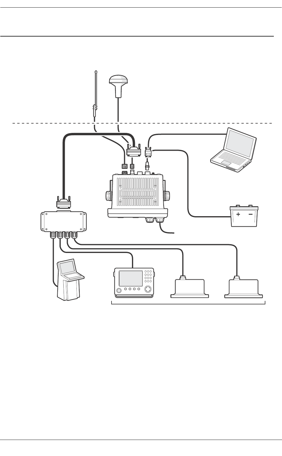
4Installation
The Protec-W AIS transceiver has been designed for ease of installation. The transceiver is a ‘one box’ design
containing both the transceiver and display. An external junction box is provided to simplify connection of
sensor and display data wiring. A typical system and connection diagram is provided in Figure 35.
Figure 35 Typical AIS transceiver connection
The main elements of installation are:
1. Mount the transceiver and junction box in a suitable location.
2. Install VHF antenna according to manufacturers instructions.
3. Install the GPS antenna.
4. Connect data interfaces.
5. Apply power and configure the transceiver.
6. Confirm correct operation.
7. Complete the installation log.
GPS antenna
12/24V DC Supply
Pilot equipment
Optional PC
VHF antenna
Above decks
Below decks
Junction box
Displays
(ECDIS, RADAR)
Ship’s sensor data
(DGPS, GYRO, Heading)

Installation
Page 32
4.1 What’s in the box?
Figure 36 shows the items included with your AIS transceiver purchase. The following section gives a brief
overview of each item. Please ensure all items are present and if any of the items are missing please contact
your dealer.
Figure 36 What’s in the box
●Protec-W Class A AIS transceiver/Inland AIS
The main transceiver and display.
●Data cable
A 1m (3.3ft) long, 50 way data cable to connect the transceiver serial data ports to the junction box.
●Junction box
Provides screw terminals for the data connections to ships sensors and display systems.
●Power cable
A 2m (6.6ft) long power cable to supply the transceiver. The power cable also include alarm output
connections.
●Trunnion bracket
Bracket for mounting the transceiver above a flat surface (e.g., on top of an instrument panel).
●Panel mount brackets
Clamp brackets used when mounting the transceiver through a panel (flush mount).
●Fixing screws
Eight fixing screws are provided for mounting the transceiver (when using the trunnion bracket) and
the junction box.
●User and installation manual
This document - please read thoroughly before attempting to install and commission the transceiver.
●Quick start guide
The quick start guide gives a handy one page reference for the installation process.
●Support tools CD
Contains software tools for configuration of the AIS transceiver and software upgrade.
●Mounting template
Template for cutting an aperture when panel mounting the transceiver.
Product manual
Mounting template
Data cable Power cable
CD
Transceiver
Trunnion bracket
Panel mount brackets
Junction box
Quick
installation
guide
GPS antenna
Quick
operation
guide
Screws

Installation
Page 33
4.2 Preparing for installation
In addition to the items provided with the Protec-W transceiver the following items will be required to complete
the installation:
4.2.1 VHF Antenna
Connection of a suitable VHF antenna will be required for the AIS transceiver to operate. A standard marine
band VHF antenna such as that used with VHF voice radios is sufficient. The antenna cable should be
terminated with a PL-259 (or UHF) connector. Please take note of the warnings listed at the start of this manual
regarding the installation and use of antennas.
4.2.2 Antenna cables
The supplied GPS antenna is provided with 10 metres (32.8ft) of cable. If this is not sufficient to reach between
the desired GPS antenna location and the AIS transceiver you will require an extension cable. Please contact
your dealer for details. For reference the GPS antenna connector type on the AIS transceiver is a TNC
receptacle and is intended to mate with a TNC jack connector on the GPS antenna cable.
4.2.3 GPS antenna mount
A mounting bracket is required for the supplied GPS antenna. The antenna has a standard one inch 14 TPI
pole mount thread. You should source and install a compatible antenna bracket suitable for the installation
location.
4.2.4 Data interface cables
Suitable screened, multi core cable will be required to connect the ships sensor (DGPS, Gyro etc.) data ports
to the AIS junction box.
4.3 Installation procedures
Before beginning installation of your AIS transceiver, please ensure you have the necessary additional items
as detailed in section 4.2. It is strongly recommended that you read all of the instructions in this manual prior
to installation.
If after reading this manual you are unsure about any aspect of the installation process please contact your
dealer for advice. The following sections explain the installation process step by step for each of the main
system elements.
4.3.1 Step 1 - Installing the AIS transceiver
Please note the following guidelines when selecting a location for your AIS transceiver:
●The AIS transceiver must be fitted in a location where it is at least 30cm (1ft) from a compass or any
magnetic device.
●There should be adequate space around the AIS transceiver for routing of cables. See Figure 37 for
details of the AIS transceiver dimensions.
●The ambient temperature around the AIS transceiver should be maintained between -15°C and +55°
(5°F to 131°F). Ensure adequate ventilation is present when panel mounting the transceiver.
●The AIS transceiver should not be located in a flammable or hazardous atmosphere such as in an
engine room or near to fuel tanks.
●The AIS transceiver must be installed in a 'below decks' environment protected from the weather.
●The transceiver is supplied with four self tapping screws for attachment of the AIS transceiver to a
suitable surface using the trunnion bracket. Please refer to Figure 38 for guidance.
●The transceiver is supplied with panel mount clamps for flush mounting through an instrument panel.
Please refer to Figure 39 for guidance. Access behind the panel is required when using this mounting
option.
●The AIS transceiver should be mounted in a location where the display is visible to the user at the
position from which the vessel is normally operated.
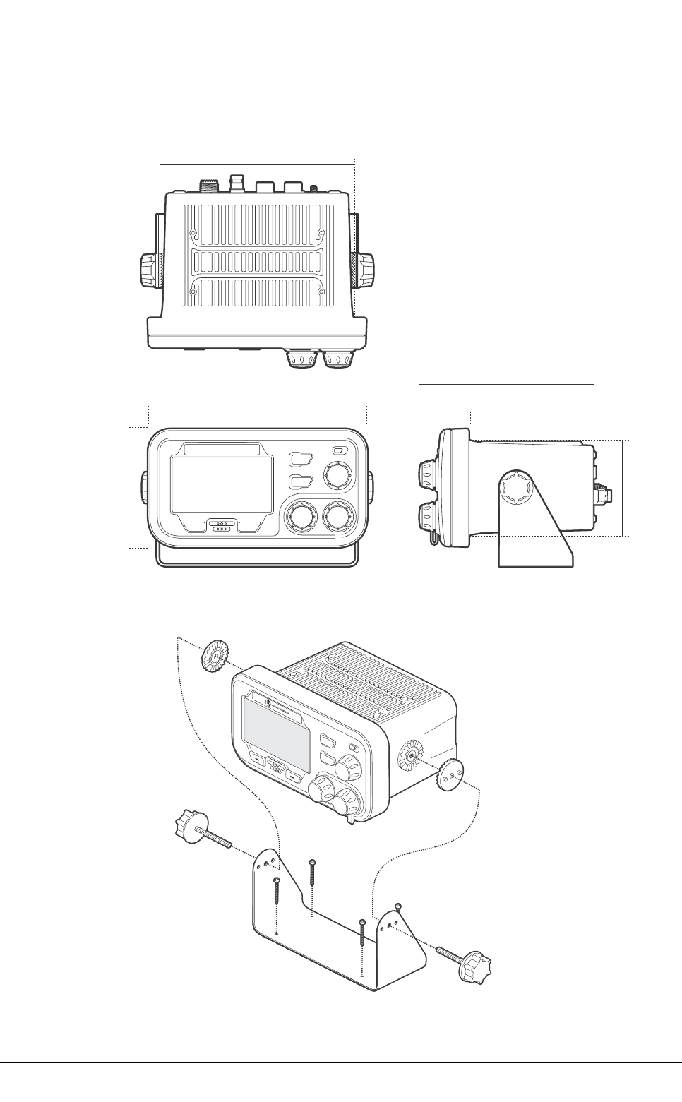
Installation
Page 34
●An AC power port should be available near to the pilot plug. A pilot plug is located on the front panel
of the AIS transceiver and can also be relocated using the junction box. Please refer to section 4.4.2
for guidance.
Figure 37 AIS transceiver dimensions
Figure 38 Mounting the AIS transceiver
105 mm
85 mm
195 mm
172 mm
112 mm
157 mm
MENU
BACK
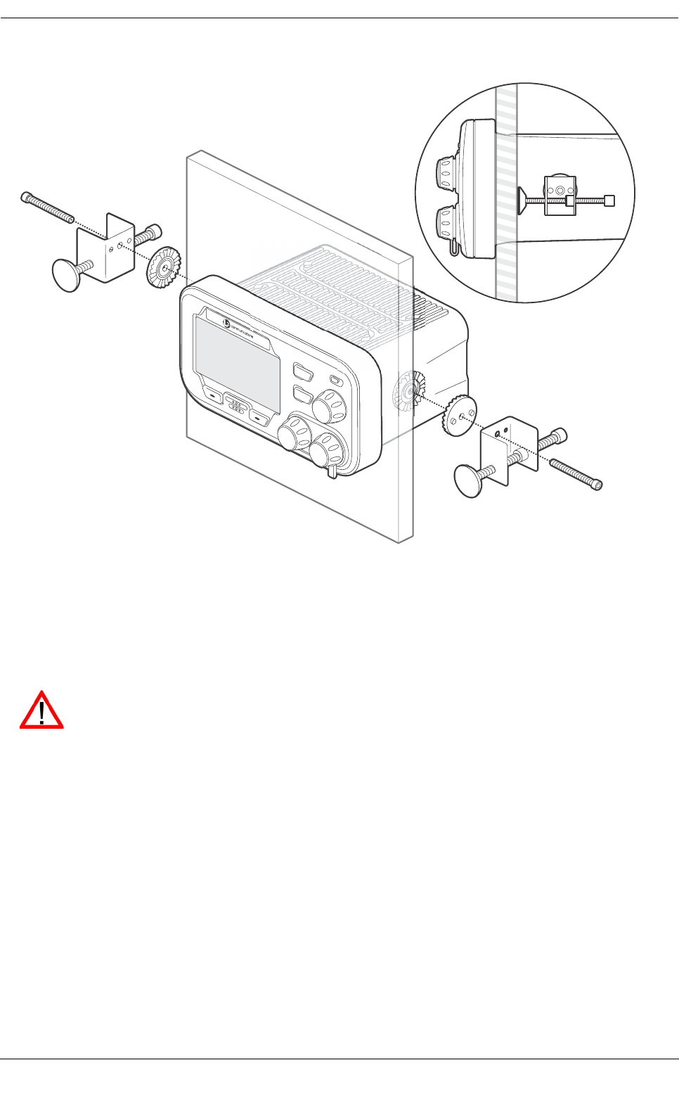
Installation
Page 35
Figure 39 Panel mounting the AIS transceiver
4.3.2 Step 2 - Installing the junction box
The AIS transceiver receives data from the ship’s sensors via the 50 way data cable which connects to the rear
of the transceiver. The other end of this cable is connected to the junction box which provides a convenient
screw terminal system for connection of ships sensor data cables.
Please note the following guidelines when selecting a location for the AIS junction box:
●There should be adequate space around the junction box for routing of cables. See Figure 40 for
details of the junction box dimensions.
●The ambient temperature around the junction box should be maintained between -15°C and +55°
(5°F to 131°F).
●The junction box should not be located in a flammable or hazardous atmosphere such as in an engine
room or near to fuel tanks.
●The junction box must be installed in a 'below decks' environment protected from the weather.
●The transceiver is supplied with four self tapping screws for attachment of the junction box to a
suitable surface. Please refer to Figure 41 for guidance.
●The junction box must be located within 1m (3.2ft) of the AIS transceiver to allow for the length of the
supplied data interface cable.
MENU
BACK
To meet IMO requirements the AIS transceiver must be able to transmit at least Speed over
Ground (SOG), Course over Ground (COG) and Rate of Turn (ROT) information. This data is
obtained by connecting data outputs from the ship’s DGPS, Gyrocompass and other sensors to
the transceiver via the junction box.
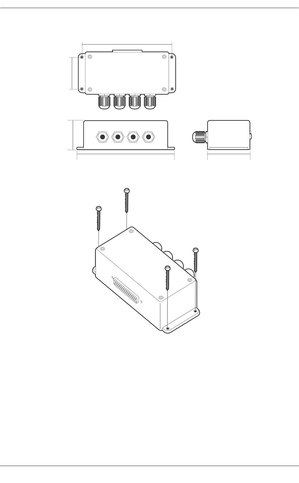
Installation
Page 36
Figure 40 Junction box dimensions
Figure 41 Mounting the junction box
4.3.3 Installing the GPS antenna
The Protec-W AIS transceiver includes an internal GPS receiver for time synchronisation. An independent GPS
antenna is required for this receiver in addition to any GPS equipment already installed on board.
For mounting of the GPS antenna supplied with your AIS transceiver you will require a one inch 14 TPI pole
mount. Contact your dealer to source a mount suitable for the installation location.
Please note the following guidelines when selecting a location for the GPS antenna:
●The GPS antenna mount should be secured to a rigid surface.
●The GPS antenna should be located where it has a clear, unobstructed view of the sky overhead.
●The GPS antenna should be mounted as high as possible, however it is not recommend the antenna
is mounted on a top of a high mast where the motion of the vessel will cause the antenna to swing
and potentially reduce the accuracy of the GPS position. See Figure 42 for guidance.
178 mm
52 mm
76 mm
165 mm
58 mm
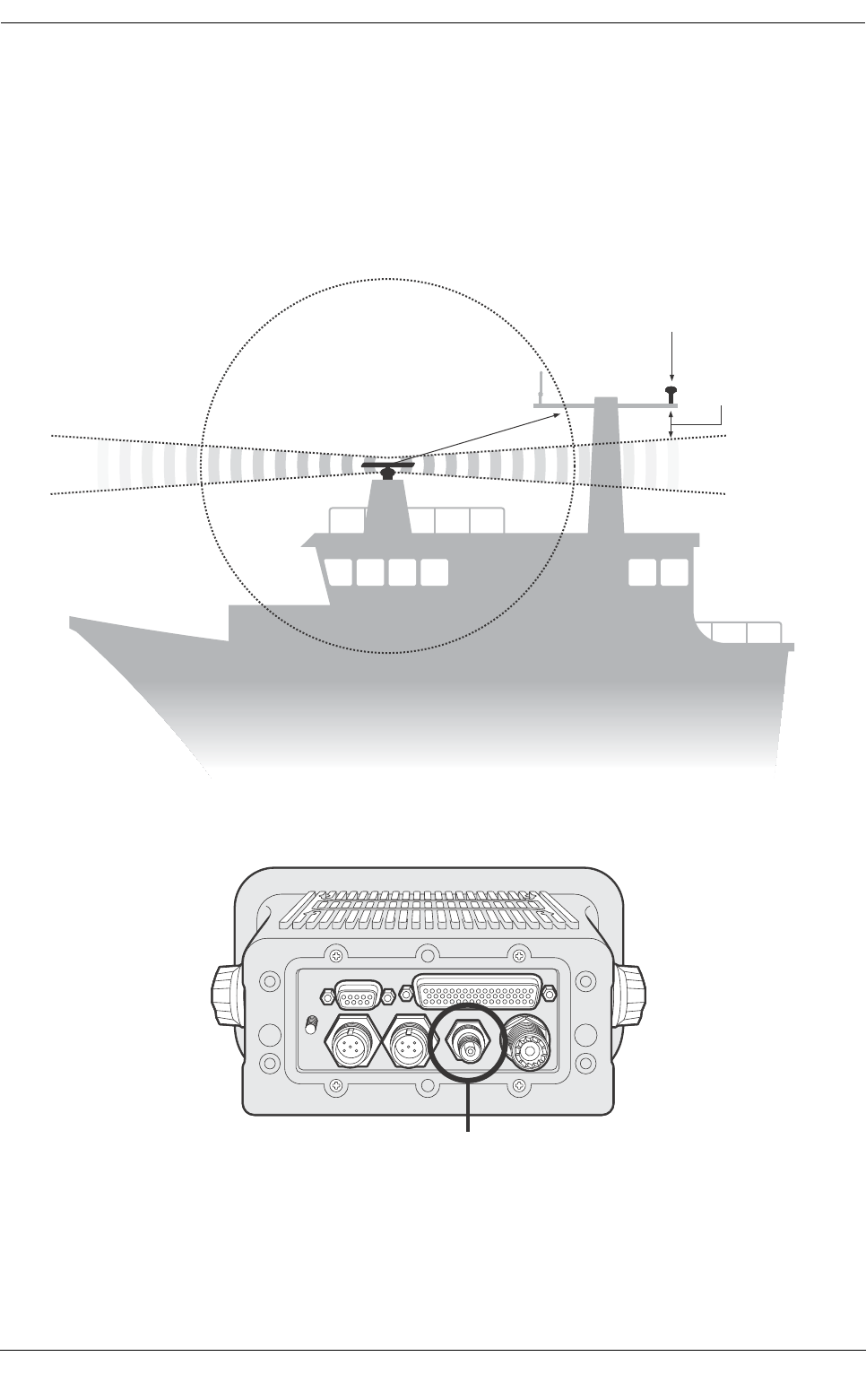
Installation
Page 37
●If possible mount the antenna at least 5m (16ft) from any RADAR or Satellite communications
antennas, and ensure the GPS antenna is not in the beam path from any RADAR antenna.
●Route the GPS antenna cable through the pole mount and then to the AIS transceiver. If extension
cables are required all junctions should be made using appropriate co-axial connectors and made
watertight.
●Connect the GPS antenna cable to the GPS connector on the AIS transceiver as shown in Figure 43.
Figure 42 GPS antenna location
Figure 43 GPS antenna connection
4.3.4 Installing the VHF antenna
The Protec-W AIS transceiver requires a dedicated VHF antenna for communications. A standard marine VHF
antenna is suitable.
GPS antenna should
be at least 5m (16ft)
from RADAR or Satellite
communication
antennas
Away from RADAR
beam path
GPS antenna mounted
on a rigid surface
GPS antenna connection
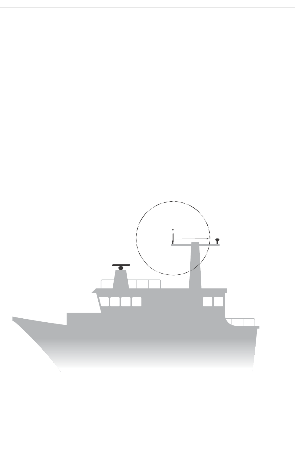
Installation
Page 38
Please note the following guidelines when selecting and locating the AIS VHF antenna:
●The VHF antenna should be located as high as possible and positioned as far from other antennas as
possible.
●The VHF antenna should have omnidirectional vertical polarisation.
●Where possible the VHF antenna should be installed at least 3m (10ft) away from other transmitting
radio, satellite and RADAR antennas.
●Ideally the AIS VHF antenna should be mounted directly above or below the ship’s primary VHF
radiotelephone antenna, with no horizontal separation and with a minimum of 2m vertical separation.
If it is located on the same horizontal level as other antennas, the distance apart should be at least
10m. Refer to Figure 44 for further guidance.
●The VHF antenna cable should be kept as short as possible to minimise signal loss. High quality. low
loss coaxial cable appropriate to the installation location should be used.
●The VHF antenna cable should be terminated in a PL-259 co-axial connector for connection to the
AIS transceiver.
●Any outdoor installed connectors in the antenna cables should be waterproof by design.
●Antenna cables should be installed in separate signal cable channels at least 10cm (4ins) away from
power supply cables. Crossing of cables should be done at right angles and sharp bends in the
antenna cables should be avoided.
●Connect the VHF antenna cable to the VHF connector on the AIS transceiver as shown in Figure 45.
Figure 44 VHF antenna installation
Positioned at least 3m (10ft)
from other transitting radio,
satellite and RADAR antennas
VHF antenna
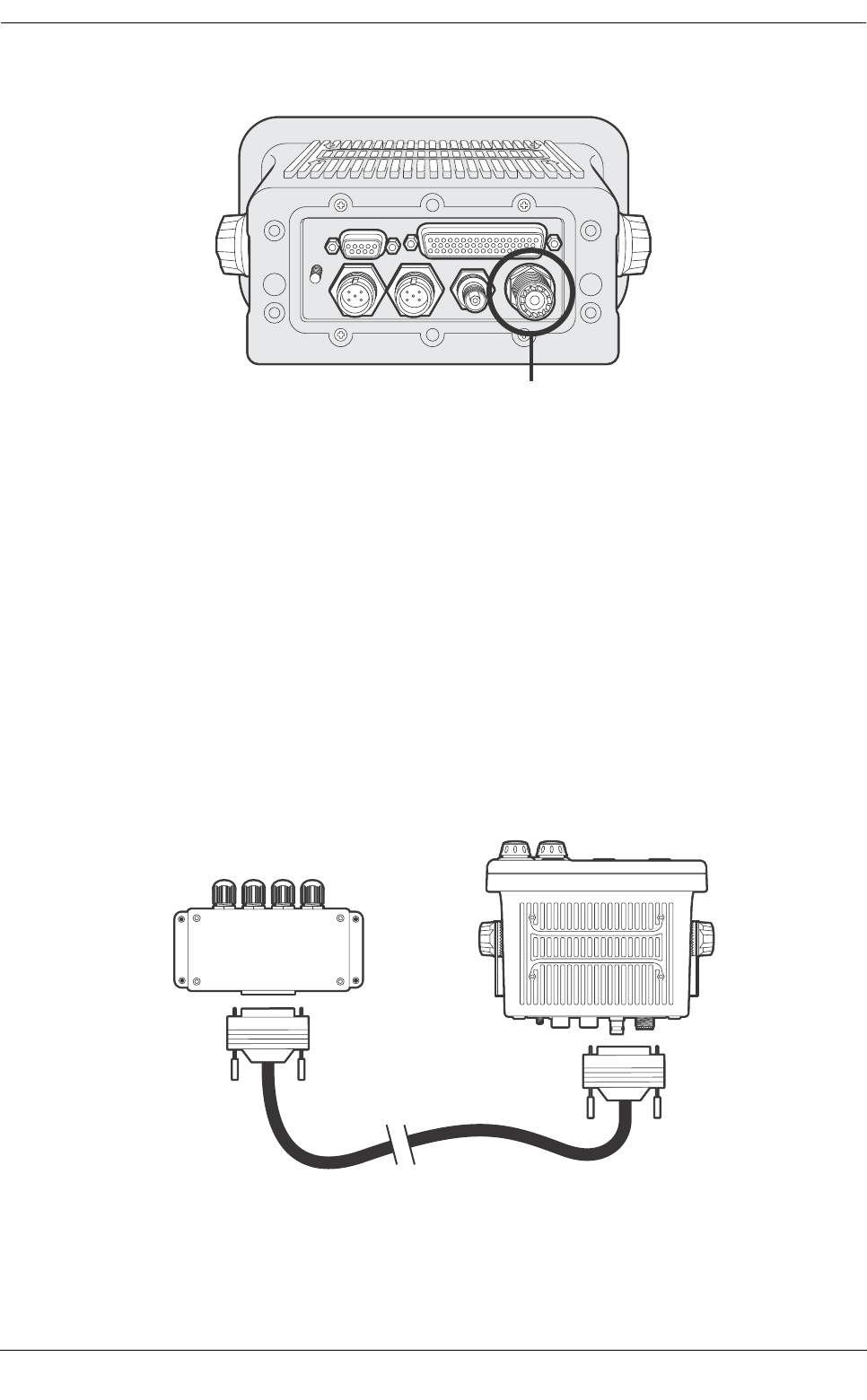
Installation
Page 39
Figure 45 VHF antenna connection
4.4 Connecting the equipment
With the transceiver, junction box and antenna installed it is now possible to connect the equipment in
preparation for commissioning.
4.4.1 Antenna connections
If antenna connections have not already been made the GPS and VHF antennas should now be connected to
the transceiver. Refer to Figure 43 and Figure 45 for guidance.
4.4.2 Data connections
The Protec-W transceiver is supplied with a 1m (3.2ft) 50 way data cable for interconnection of the transceiver
and junction box.
Connect the junction box to the transceiver using the data cable as indicated in Figure 46.
Figure 46 Connecting the junction box to the transceiver
VHF antenna connection
Transceiver
Junction box
Installation
Page 40
4.4.3 Sensor configuration
The Protec-W transceiver has seven NMEA0183 (IEC61162-1/2) data ports for connection of ship’s sensors
and display equipment as described in Table 3. There are three input ports for ship’s sensor data and three
bidirectional ports for connection of display equipment such as Radar or electronic chart displays. It is
recommended that an AIS compatible electronic charting system is connected to the Protec-W transceiver for
display of AIS targets. To comply with IMO regulations the AIS must be connected to speed over ground
(SOG), course over ground (COG), heading, rate of turn (ROT) and position information sources.
The three sensor ports are input only data ports for the connection of data from ships sensors. The four
remaining ports are bi-directional high speed connections supporting data input and output from the AIS. These
ports are suitable for connection to ECDIS, AIS enabled RADAR displays and Pilot equipment.
All data input connections are optically isolated.
Table 3 Serial data ports
All sensor ports can be configured via the sensor configuration menu which can be found under the Main
menu>Installation>Sensor configuration menu option.
The sensor configuration menu also includes the ability to disable the requirement for external GPS sensors to
provide a DTM (Datum) sentence, as not all external GPS devices provide this sentence.
4.4.4 Junction box connections
The junction box provides screw terminal connections for each of the seven data ports. The connections and
functions of each connection are defined in Table 4. All connections are labeled on the junction box PCB for
clarity. A diagram showing connections available inside the junction box is provided in Figure 47.
Use of shielded cable is recommended when connecting ships sensors and display systems to the junction box
Connect the cable shield to the terminal block marked ‘shields’ in the junction box. It is possible to remove the
PCB from the junction box enclosure to aid connection of cables to the screw terminals during installation.
Data port Function Type Default Baud rate
1Sensor 1 input
(DGPS -
COG/SOG/LAT/LON)
Receive only 4800
2Sensor 2 input
(Rate of Turn)
Receive only 4800
3Sensor 3 input
(Gyro heading)
Receive only 4800
4External display / ECDIS Bi-directional 38400
5Pilot port Bi-directional 38400
6Long Range Bi-directional 38400
7DGPS beacon receiver Bi-directional 4800
If an external GPS device which does not provide a DTM sentence is connected to the
transceiver and the transceiver is configured to require DTM sentences, the external GPS data
will not be accepted by the transceiver. If no DTM sentence is required the WGS84 datum will be
used as a coordinate origin and the external GPS device must be configured to output position
using this datum.
Do not connect the shield to both the external equipment and the junction box. Connect at only
one end.
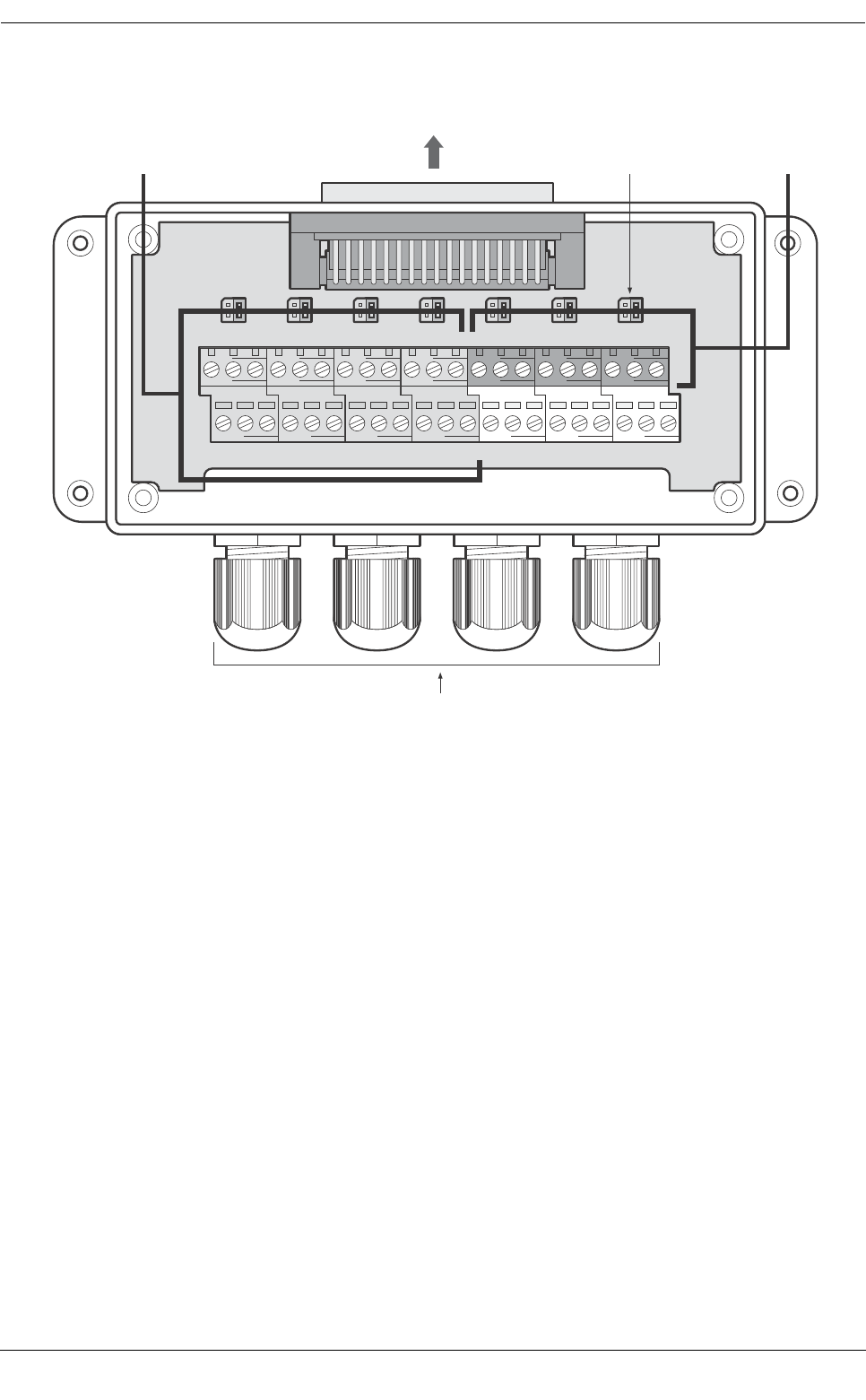
Installation
Page 41
Figure 47 Junction box connections
Cable glands
To transceiver
Bidirectional data ports Sensor data inputsTermination jumpers
AB
EXT_DISP_IN
GND A B
PILOT_IN
GND A B
DGPS_IN
GND A B
LR_IN
GND A B
SEN1
GND A B
SEN2
GND A B
SEN3
GND
AB
EXT_DISP_OUT
GND A B
PILOT_OUT
GND A B
DGPS_OUT
GND A B
LR_OUT
GND COM NC
ALARM
NO GND GND
SHIELD
GND SM BS
SWITCHES
COM

Installation
Page 42
Table 4 Serial data port connections
*This setting relates to IEC61162-1 or IEC61162-2 operation.
Data port Junction box signal
label Description Function
Sensor 1 SEN1 A Sensor port 1 input A Connect to data source, typically
ships primary GPS at 4800baud.
This port can be configured to
operate at either 4800 or 38400
baud*.
SEN1 B Sensor port 1 input B
SEN1 GND Sensor port 1 isolated ground
Sensor 2 SEN2 A Sensor port 2 input A Connect to data source, typically
gyro or heading. This port can be
configured to operate at either
4800 or 38400 baud*.
SEN2 B Sensor port 2 input B
SEN2 GND Sensor port 2 isolated ground
Sensor 3 SEN3 A Sensor port 3 input A Connect to data source, typically
ROT or speed. This port can be
configured to operate at either
4800 or 38400 baud*.
SEN3 B Sensor port 3 input B
SEN3 GND Sensor port 3 isolated ground
External
display
EXT_DISP_IN A External display input A Connect to the data output of an
external display system, typically
an ECDIS. This port operates at
38400 baud.
EXT_DISP_IN B External display input B
EXT_DISP_IN GND External display input ground
(isolated)
EXT_DISP_OUT A External display output A Connect to the data input of an
external display system, typically
an ECDIS. This port operates at
38400 baud.
EXT_DISP_OUT B External display output B
EXT_DISP_OUT GND External display output
ground
Pilot PILOT_IN A External display input A Connections for the pilot port.
These connections duplicate the
pilot plug on the front panel of the
transceiver and can be used to
relocate the pilot plug if required.
If relocating the pilot plug note
that AMP/Receptacle (Square
Flanged (-1) or Free-Hanging
(-2)), Shell size 11, 9-pin, Std. Sex
206486-1/2 or equivalent with the
following terminations must be
used.
- TX A is connected to Pin 1
- TX B is connected to Pin 4
- RX A is connected to Pin 5
- RX B is connected to Pin 6
- Shield is connected to Pin 9
PILOT_IN B External display input B
PILOT_IN GND External display input ground
(isolated)
PILOT_OUT A External display output A
PILOT_OUT B External display output B
PILOT_OUT GND External display output
ground
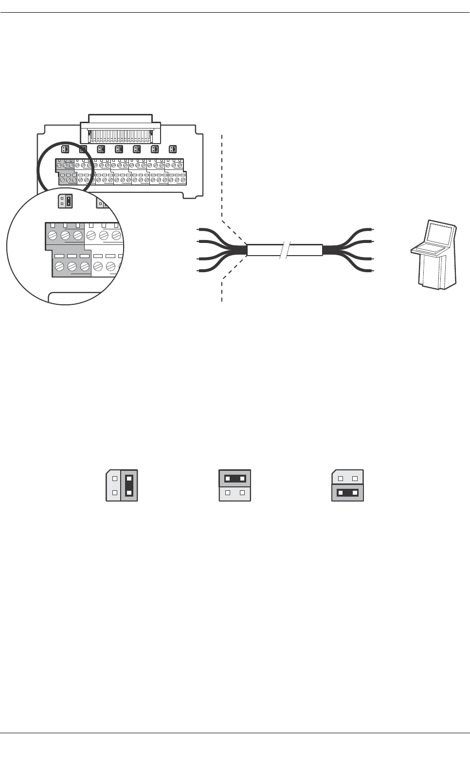
Installation
Page 43
An example of connection to external display equipment is provided in Figure 48, and connections to other
equipment and sensors follow the same scheme. To determine the ‘A’ and ‘B’ signal lines on external
equipment use a digital volt meter to measure the signal line voltage referenced to ground. If the voltmeter
shows a negative voltage the ‘A’ signal line is being measured, a positive voltage indicates the ‘B’ signal line.
Figure 48 Example connection to external display equipment
The junction box provides jumpers to select alternative line termination configurations for data input
connections from remote equipment. The line termination options are:
●None - no line termination, suitable for short cable runs less than 10m (as supplied).
●R - 120 Ohm line termination, suitable for longer cable runs greater than 10m.
●RC - AC 120 Ohm / 1uF termination. Not used.
Select the appropriate line termination option for each data input connection using the jumper adjacent to the data
input connection in the junction box. The jumper positions for each termination option are shown in Figure 49.
Figure 49 Line termination options
AB
EXT_DISP_IN
GND A B
PILOT_IN
GND A B
DGPS_IN
GND A B
LR_IN
GND A B
SEN1
GND A B
SEN2
GND A B
SEN3
GND
AB
EXT_DISP_OUT
GND A B
PILOT_OUT
GND A B
DGPS_OUT
GND A B
LR_OUT
GND COM NC
ALARM
NO GND GND
SHIELD
GND SM BS
SWITCHES
COM
AB
EXT_DISP_IN
GND A B
PILOT_IN
GND
AB
EXT_DISP_OUT
GND A B
PILOT_OUT
GND
Transmit A
External display system.
e.g. ECDIS
Connect shield if required
Transmit B
Receive A
Receive B
EXT_DISP_IN A
EXT_DISP_IN B
EXT_DISP_OUT A
EXT_DISP_OUT B
No line termination
(default)
120 Ohm line
termination (R)
120 Ohm / 1uF line
termination (RC)
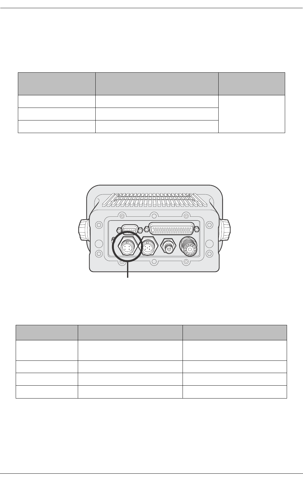
Installation
Page 44
Along with data port connections the junction box also provides connections to the AIS transceiver alarm relay
contacts. The common and normally open alarm contacts are duplicates of the alarm relay connections
available at the power connector (see Table 5) whilst the normally closed contact is only provided at the junction
box. The alarm relay connections are described in Table 5. Use the alarm connections appropriate to the
vessels alarm system.
Table 5 Alarm relay connections
4.4.5 Power and alarm connections
Power is connected to the transceiver via the supplied four way power and alarm cable as shown in Figure 50.
Figure 50 Power connection
The power and alarm cable contains four wires which should be connected according to Table 6.
Table 6 Power supply connections
*Connection to an emergency power source is an IMO requirement for SOLAS vessels.
The power supply current ratings and recommended fusing or circuit breaker currents are as follows:
●A 12VDC supply should be able to provide 4.0A and be fused at 8.0A.
●A 24VDC supply should be able to provide 2.0A and should be fused at 4.0A.
Junction box alarm
connection Function Contact rating
COM Alarm relay common connection
220V or 2A or 60W
maximum
NC Alarm relay normally closed connection
NO Alarm relay normally open connection
Wire colour Function Connect to
Brown Power supply + 12V or 24V DC power supply from
ships emergency power source*
Black Power supply - Power supply ground
White Alarm relay normally open contact Bridge alarm system
Blue Alarm relay common contact Bridge alarm system
Power connection
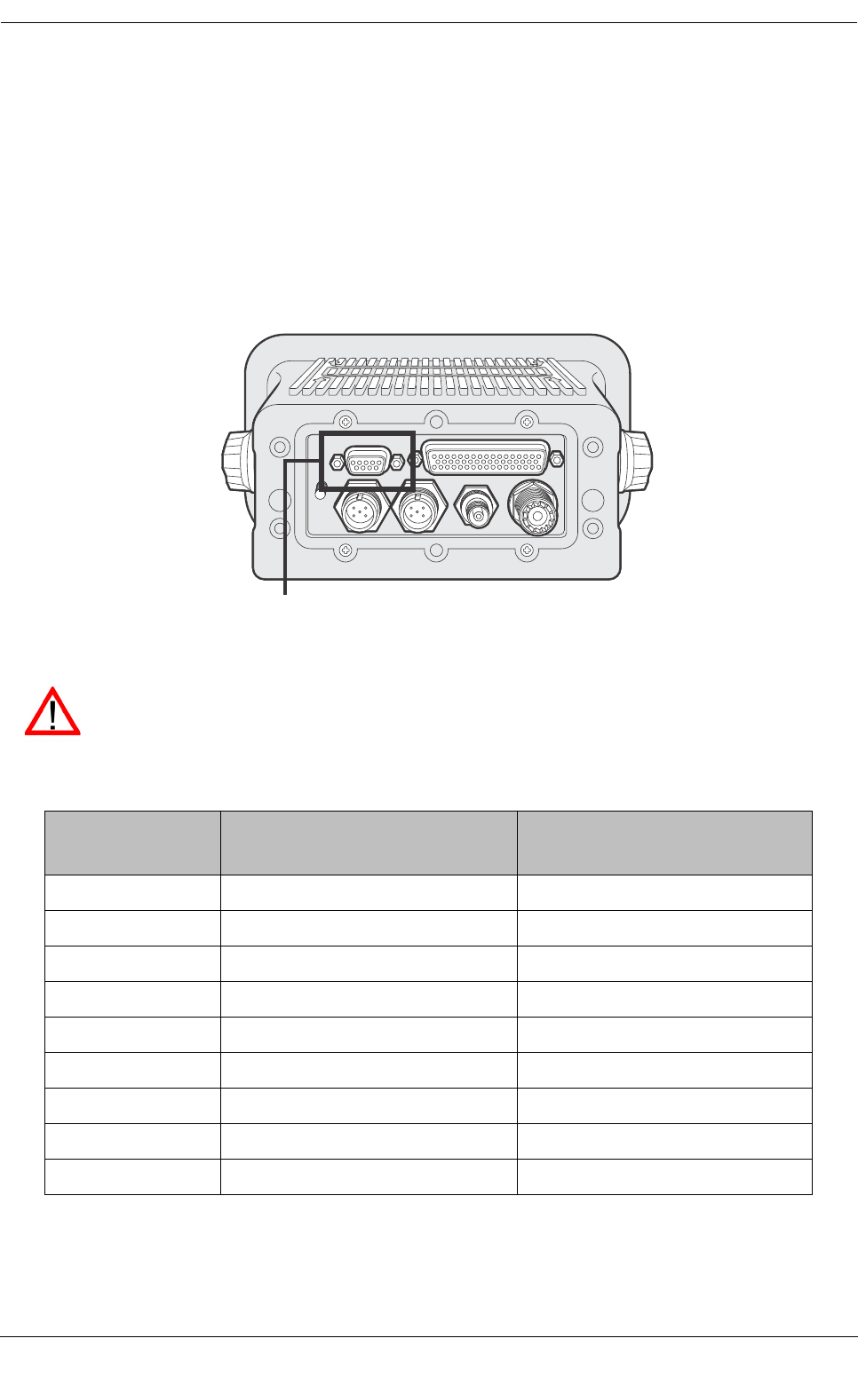
Installation
Page 45
The alarm relay is rated to 220VDC or 2ADC or 60W maximum. The alarm connections provided at the power
connections are a duplicate of the those available via the junction box and described in section 4.4.
A chassis ground stud is provided on the rear panel of the transceiver. Note that the transceiver chassis is
isolated from the incoming power supply so this stud must not be connected to power supply ground.
4.4.6 PC data connection
A 9 way D-type connector is provided on the rear panel of the Protec-W transceiver. This interface allows direct
connection to a PC RS232 interface and can be used for installation, diagnostics or external display
connection. The default configuration for this interface allows connection of an ECDIS or charting system and
duplicates the ‘External display’ port in the junction box.
Figure 51 PC data (RS232) connection
The pin allocation for the 9 way D-type socket on the rear panel of the transceiver is shown in Table 7.
Table 7 Pin allocation for the 9 way D-type socket
Transceiver 9 Way
D-type pin Signal Function
1No connection
2RS232 Transmit Connect to PC RS232 receive
3RS232 Receive Connect to PC RS232 transmit
4No connection
5RS232 Ground Connect to PC RS232 ground
6No connection
7No connection
8No connection
9No connection
PC data (RS232) connection
The RS232 port is galvanically isolated from the incoming power supply.

Installation
Page 46
4.5 Configuring the Protec-W transceiver
Once all connections have been made the transceiver can be powered and configured for operation. During
configuration information about the vessel on which the transceiver is installed is entered into the transceiver.
It is important this information is entered accurately as it will be broadcast to other AIS equipped vessels and
shore stations.
Once configuration is completed the installation record found at the rear of this manual should be completed
and retained on board the vessel.
4.5.1 Pre configuration checks
To proceed with configuration the following steps should already have been completed:
●The transceiver is fixed to the vessel
●VHF and GPS antennas have been installed and connected to the transceiver
●The data cable has been connected between the transceiver and junction box
●Ships sensors and AIS enabled display equipment have been connected to the junction box
●Power has been connected to the transceiver and the transceiver is operational (the display is active).
The following configuration instructions assume the installer is familiar with the Protec-W user interface, details
of which can be found in the Operation section of this manual.
4.5.2 Configure vessel identification information
The transceiver must be configured with information about the vessel on which it is installed prior to operation.
The following information is required:
●MMSI - Vessel MMSI number (Maritime Mobile Service Identity), this can usually be found on the
ships VHF radio license and should be the same MMSI as used for the VHF / DSC radio.
●Name - Vessel Name (limited to 20 characters)
●Call sign - Vessel radio call sign (limited to 7 characters)
●IMO No. - Vessels IMO identification number (if applicable)
●Dimensions giving the location of the GNSS antenna connected to the AIS transceiver (Internal GPS)
●Dimensions giving the location of the GNSS antenna connected to any external position source
connected to the AIS transceiver
To enter the vessel identification information press the ‘Menu’ key and select the ‘Installation’ then ‘Set
identification’ option. You will be prompted to enter a password at this stage, the default password is ‘00000000’
(eight zeros). Refer to section 3.15 for more information on passwords and security. The vessels MMSI, Name,
Call sign and IMO number can be entered on the screen displayed after successful password entry.
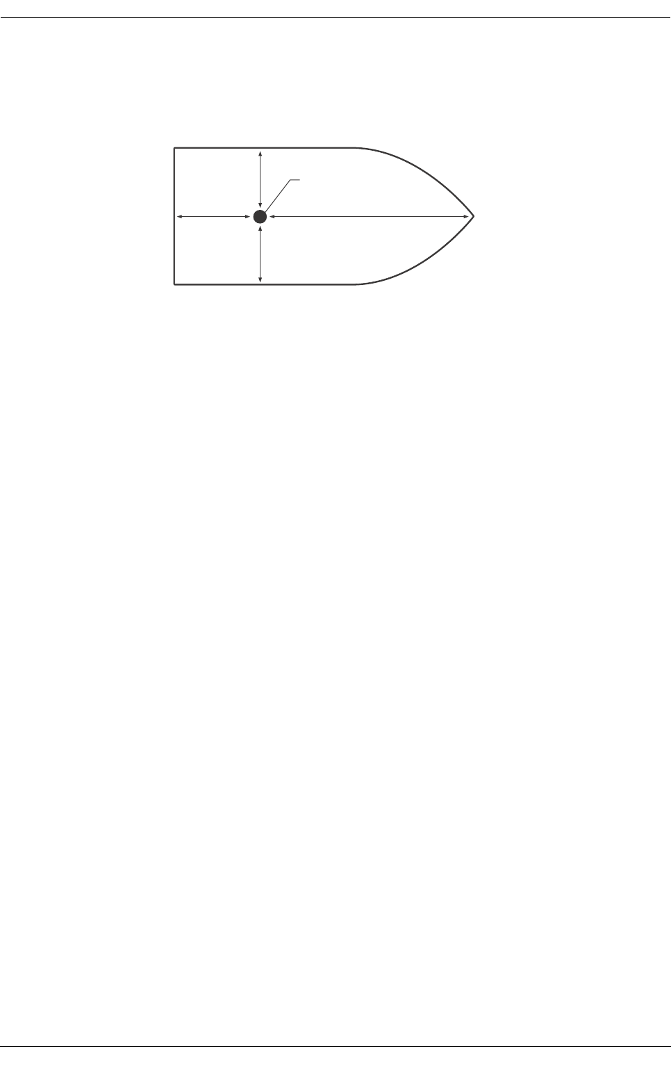
Installation
Page 47
To enter the GNSS antenna locations go back to the main menu and select the ‘Dimensions’ then ‘Internal’ or
'External’ option as appropriate. Dimensions for both the internal and external GNSS antennas must be entered
if an external GNSS is connected to the AIS transceiver. The antenna dimensions should be entered in metres
according to the diagram provided in Figure 52.
Figure 52 Vessel dimensions measurement
4.5.3 Configure voyage related data
The transceiver must be configured with information about its voyage prior to operation. The following
information is required:
●Nav Status - Navigational status selected from the list below:
○0 - Under way using engine.
○1 - At anchor.
○2 - Not under command.
○3 - Restricted manoeuvrability.
○4 - Constrained by her draught.
○5 - Moored.
○6 - Aground.
○7 - Engaged in fishing.
○8 - Under way sailing.
○9 to 14 - reserved for future use.
○15 - not defined (default setting).
●Destination - Ships next destination port (limited to 20 characters).
●ETA - Estimated time / date of arrival at destination (using UTC time).
●Draught - Maximum present static draught to the nearest 1/10th of a metre.
●Ship and cargo type - a two digit code selected using Table 8. Where the second digit is represented
by [n] the appropriate code for the second digit should be selected from Table 9.
●Crew - Number of crew on board (optional).
To enter the vessel identification information press the ‘Menu’ key and select the ‘Voyage Data’ option. The
vessels Nav. status, Destination, ETA, Draught, Type and number of crew can then be entered.
Ref A
Antenna
Ref A + Ref B = Length in metres Ref C + Ref D = Beam in metres
Ref B
Stern Bow
Ref C
Ref D

Installation
Page 48
Table 8 Vessel types and their corresponding vessel type codes
Table 9 Type codes for vessels carrying cargo
Vessel type Type
code
Reserved (do not use) 1[n]
Wing in ground craft 2[n]
Fishing 30
Towin g 31
Towing and length of tow exceeds 200m or breadth exceeds 25m 32
Engaged in dredging or underwater operations 33
Engaged in diving operations 34
Engaged in military operations 35
Sailing 36
Pleasure craft 37
(HSC) High speed craft 4[n]
Pilot vessel 50
Search and rescue vessel 51
Tug 52
Port tender 53
Vessel with anti-pollution facilities 54
Law enforcement vessel 55
Spare - for local use 56
Spare - for local use 57
Medical transports (under the 1949 Geneva conventions and additional protocols) 58
Ships according to RR Resolution No. 18 (Mob-83) - Relating to the Procedure for Identifying
and Announcing the Position of Ships and Aircraft of States Not Parties to an Armed Conflict
59
Passenger ship 6[n]
Cargo ship 7[n]
Tanker 8[n]
Other type of ship 9[n]
Cargo type Second digit
(where not predefined)
All ships of this type 0
Carrying DG, HS, or MP, IMO hazard or pollutant category A 1
Carrying DG, HS, or MP, IMO hazard or pollutant category B 2
Carrying DG, HS, or MP, IMO hazard or pollutant category C 3
Carrying DG, HS, or MP, IMO hazard or pollutant category D 4
Reserved (do not use) 5
Reserved (do not use) 6
Reserved (do not use) 7
Reserved (do not use) 8
No additional information 9

Installation
Page 49
4.6 Changing the password
Following configuration of the transceiver the password should be changed from its default value of ‘00000000’
to another eight digit code. Password change is carried out by selecting the main menu ‘Installation’ menu, then
the ’Change password’ submenu.
A prompt for the existing password will be shown, followed by entry of the new password then confirmation of
the new password before the new password is stored and active. The password should be recorded on the
installation record found in section 9.
4.7 Confirming correct operation
Following entry of the vessel identification and voyage related information the transceiver will commence
normal operation. To complete the installation correct operation should be verified as follows:
1. Exit the menu system and return to the main operating screens. Press the 'Screen' key until the ‘Own
dynamic data’ screen is displayed.
2. Check that the displayed position, course, speed and heading are correct by comparing to the display
associated to the connected position and other data sources.
3. Check that the status icon display shows ‘OK’ and that the ‘TX’ icon flashes periodically.
4. If the vessel is in an area where other AIS equipped vessels are present press the ‘Screen’ key until
the ‘Target list' screen is displayed. Check that data from other AIS equipped vessels is displayed.
The Protec-W transceiver is now operational and should remain powered unless authorised by the local
maritime authority. The installation record at the rear of this manual should be completed and left on board the
vessel.
4.8 Regional area settings
The transceiver can be manually programmed with regional area settings. These settings control the AIS radio
channel and transmission settings within a predefined area. Regional settings can also be remotely configured
by the local maritime authority via transmissions from an AIS base station. Manual entry of regional area
settings should only be carried out if required by the local maritime authority.
The transceiver can store eight regional area settings including both remote and manual entries.
4.8.1 Creating a new regional area setting
To enter a new regional area setting press the ‘Menu' key and select the ‘Installation' and then the ‘Regional
areas’ sub-menu. The display now shows a list of the current regional area settings as shown in Figure 53.
Figure 53 Regional areas list screen
13:20:47
REGIONAL AREA SETTINGS:
Lat NE Long NE Lat SW Long SW
> --°--N ---°--E --°--N ---°--E
OK GPS
INT
EditNew
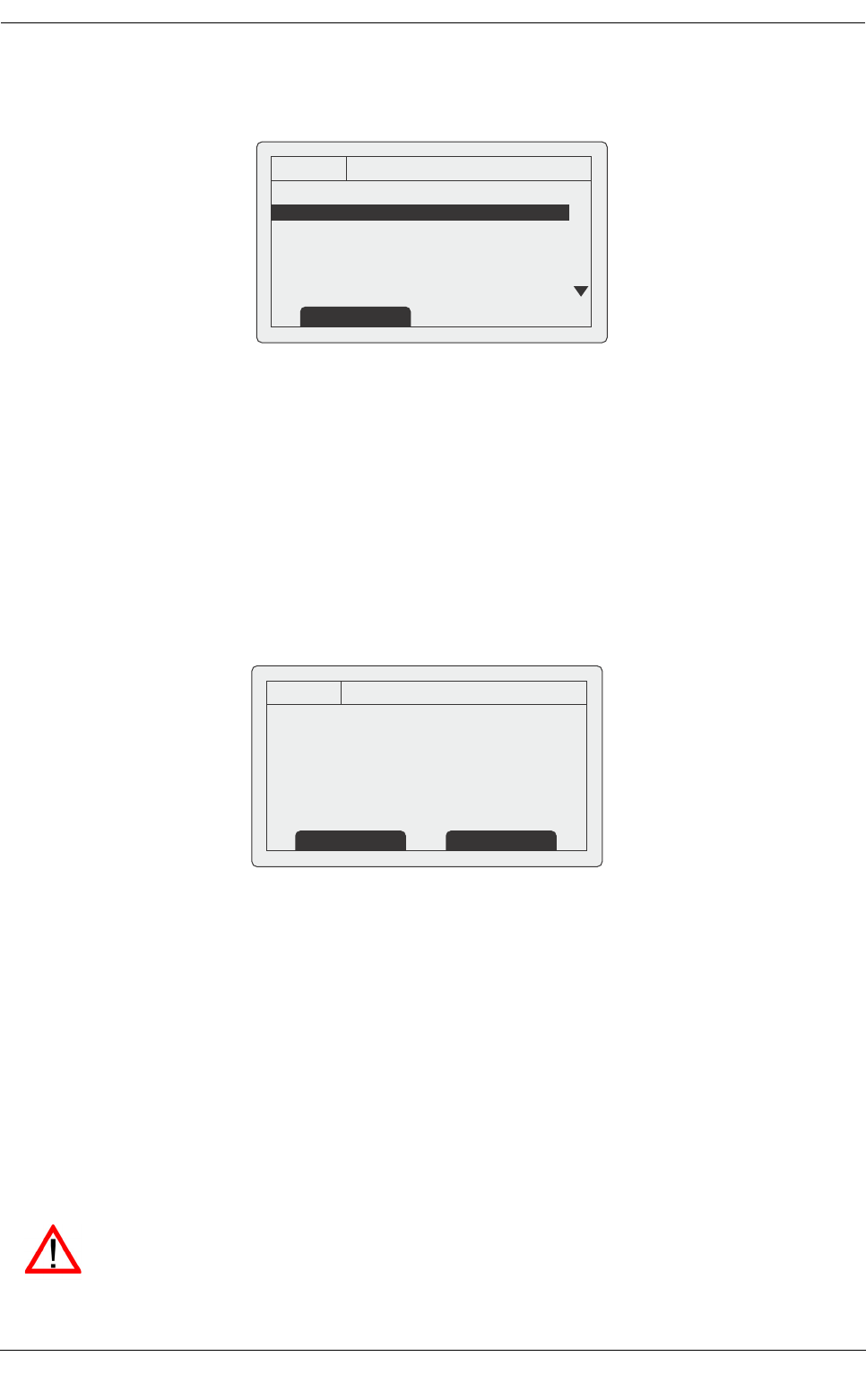
Installation
Page 50
To create the new area setting press the ‘New' function key and the edit screen shown in Figure 54 will be
displayed.
Figure 54 Regional area editing screen
1. The scroll wheel can now be used to scroll to the field to edit.
2. Select the field by pushing the scroll wheel or pressing the 'Edit’ function key.
3. Enter a value, or select from a list of possible values using the scroll wheel.
4. Press the ‘OK’ or ‘Cancel' function key to confirm or cancel the entry.
5. Repeat the process 1 - 4 for each field to be edited.
6. Press the ‘Back/Save’ function key to save the regional area setting and return to the area settings list
7. You will be prompted to confirm storage of the regional area setting with the display shown in Figure 55.
8. After confirmation of the regional settings the settings are stored and may take effect immediately de-
pending on the location of the vessel.
Figure 55 Regional area settings confirmation screen
4.8.2 Editing an existing regional area setting
To edit an existing regional area setting press the ‘Menu' key and select the ‘Installation' and then the ‘Regional
areas’ sub-menu. The display now shows a list of the current regional area settings as shown in Figure 53. Use
the scroll wheel to scroll to and select the regional area setting entry to be edited, then follow the instructions
for creating a new regional area setting in section 4.8.1.
4.9 Manually setting the transmitter power
The Protec-W transmitter has a default output power of 12.5W. If local regulations require the transmitter power
can be manually adjusted to a low power setting (1W). To adjust the transmitter output power press the ‘Menu’
key then select the ‘Installation’ sub menu followed by the ‘Set Power’ sub menu. Adjustment of the transmitter
power is password protected. Following password entry select either ‘Low power’ or ‘High power’ mode.
13:20:47
EDIT REGIONAL AREA:
In Use: No
Time of In Use: --:--:--
Info Source: Not Available
Channel A: 2087
Channel B: 2088
Channel A BW: Default
OK GPS
INT
Back
13:20:47
SAVE REGIONAL AREA:
Are you sure you want to save the
edited Regional Area?
Area settings may take effect
immediately!
OK GPS
INT
No Yes
Selecting low power mode will significantly reduce the range of transmissions from the Protec-W.
Low power mode should only be selected if local regulations of vessel operations demand it.
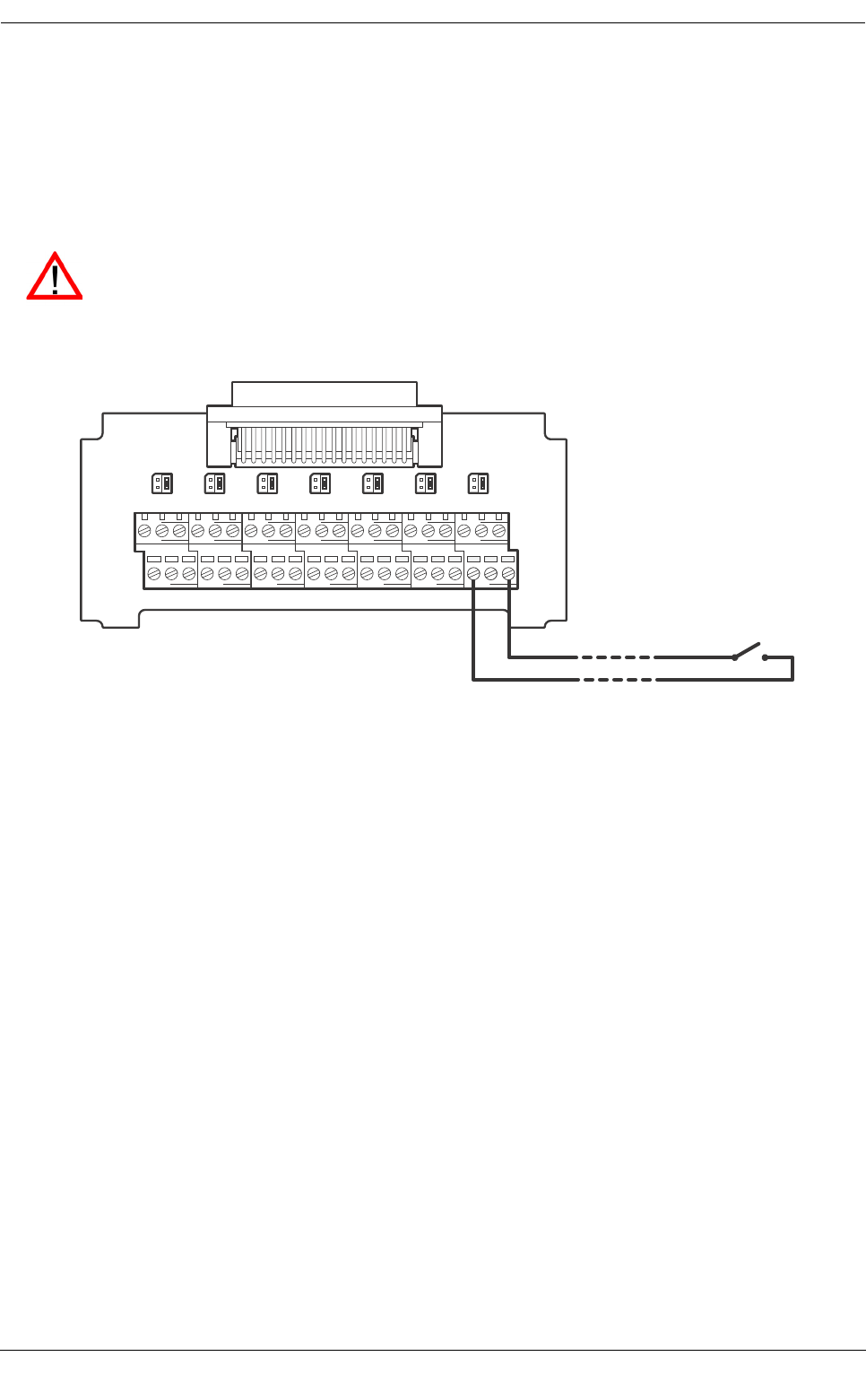
Installation
Page 51
4.10 Silent mode switch connection
An external switch can be connected to the AIS transceiver to control silent mode. To use an external switch
silent mode settings must be configured appropriately as described in section 3.18.
The external switch should be of a latching single pole type and is connected to the ‘Switches’ terminals of the
junction box as shown in Figure 56. When the connected switch is made (short circuit) silent mode will be
enabled and the Protec-W will stop transmitting the vessel position to other AIS users.
Figure 56 Silent mode switch connection
Do not connect a voltage source to the silent mode switch connections.
AB
EXT_DISP_IN
GND A B
PILOT_IN
GND A B
DGPS_IN
GND A B
LR_IN
GND A B
SEN1
GND A B
SEN2
GND A B
SEN3
GND
AB
EXT_DISP_OUT
GND A B
PILOT_OUT
GND A B
DGPS_OUT
GND A B
LR_OUT
GND COM NC
ALARM
NO GND GND
SHIELD
GND
Silent mode switch
SM BS
SWITCHES
COM

Installation
Page 52
4.11 Inland AIS
The Protec-W AIS transceiver supports both Class A (high seas / SOLAS) AIS operation and Inland AIS
operation. Switching between Class A and Inland AIS is possible via the menu system and this setting should
be made at installation depending on the environment the vessel operates in. Additional vessel and voyage
information is required for transmission when operating in Inland AIS mode and this should be configured as
described in the following sections.
4.11.1 Switching between ‘Class A’ and ‘Inland AIS’ modes
To switch between operating modes press the ‘Menu’ key and select the ‘Installation' sub menu followed by the
‘Inland configuration’ then the ‘Inland AIS Enable / Disable’ option. When the transceiver is configured to
operate in Inland AIS mode the ‘IL’ icon is shown permanently in the status bar.
4.11.2 Entering Inland vessel identification settings
Additional vessel identification information is required for Inland operation along with some changes to the
standard AIS configuration. The following additional information must be entered into the AIS transceiver:
●The vessels ENI (unique European Identifier) - this is an 8 digit number allocated to the vessel.
●The ship type as an ERI code (4 digits) selected from the table provided in section 8.
●The length of the ship to the nearest 10cm (greater accuracy than standard AIS configuration).
●The beam of the ship to the nearest 10cm (greater accuracy than standard AIS configuration).
●A quality setting for the speed, course and heading data sources connected to the AIS is required.
The quality setting can be ‘high’ or ‘low’ for each data source. The low setting should be used unless
a type approved sensor (e.g., a gyro providing heading information) is connected to the AIS
transceiver.
The additional identification information can be entered via the main menu. Press the ‘Menu' key then navigate
through the ‘Installation’, 'Inland AIS’ submenus to select the ‘Inland vessel data’ menu. This screen allows
entry of the Inland specific information described above.
The following standard AIS vessel identification information must be updated for Inland AIS:
●The IMO number should be set to ‘0’ or ‘00000000’ for an Inland vessel.
●The Call Sign should be set to the vessel’s ATIS code (as programmed into the VHF radio)
●The standard AIS ship type should be set to the most applicable ship type - refer to the ship type table
in section 8.
These updates are all made using the process described in section 4.5.
4.11.3 Entering Inland vessel voyage settings
Additional voyage related information is required for Inland operation along with some changes to the standard
AIS configuration. The following additional information must be entered into the AIS transceiver:
●The vessels load status as ‘loaded’ or ‘unloaded’.
●The number of blue cones or blue flag status for the cargo (1, 2 or 3 blue cones, or blue flag).
●The static draught of the vessel to the nearest centimetre.
The transceiver stores Class A (high seas) and Inland AIS vessel and voyage data separately so
two independent configurations are required, one for Class A and one for Inland AIS. If the
transceiver is being installed on board an Inland vessel then the standard vessel and voyage data
configuration should be carried out prior to the additional Inland configuration described below.
Inland vessel dimensions - the length and beam of the ship are entered to the nearest 10cm
when operating in Inland AIS mode. This is in addition to the vessel dimensions derived from the
GPS antenna location entered during standard configuration (see section 4.5) which is entered
in meters. The Inland specific length and breadth dimensions should be rounded upwards to the
nearest meter when entering the standard configuration. Both sets of dimensions should relate
to the maximum rectangular size of the convoy.
Installation
Page 53
●The air draught of the vessel to the nearest centimetre.
●The number of crew, passengers and other shipboard personnel.
●The number of assisting tugboats (from 0 to 6).
The additional identification information can be entered via the main menu. Press the ‘Menu' key then select
the ‘Voyage data’ sub-menu. When the AIS transceiver is operating in Inland AIS mode the voyage data entry
screen will be extended to allow input of the additional information described above.
The following standard AIS voyage information must be updated for Inland AIS:
●Destination
The voyage destination should be entered using UN terminal location codes and ERI terminal codes where
possible.
4.11.4 Other Inland AIS settings
When operating in Inland mode it is possible to connect a ‘blue sign’ switch to the AIS transceiver and also to
manually configure the AIS position reporting rate. The connection of the blue sign switch is described in
section .
Settings for the blue sign switch and reporting rate are available via the main menu by selecting the ‘Installation’
option followed by the 'Inland configuration’ sub menu.
Select the ‘Blue sign settings’ option to set up the blue sign switch. The switch can be set to ‘Available’ if a blue
sign switch is connected or 'Unavailable’ if no switch is connected.
Select the ‘Reporting rate selection’ option to manually adjust the AIS position reporting interval. The available
reporting interval settings are:
●Autonomous mode (default).
●Once every 10 seconds.
●Once every 5 seconds.
●Once every 2 seconds.
4.11.5 Blue sign switch connection
An external switch can be connected to the AIS transceiver to indicate the blue sign state when in Inland AIS
mode. If a blue sign switch is installed then the switch should be set to ‘Available' as described in section 4.11.4.
The external switch should be of a latching single pole type and is connected to the ‘Switches’ terminals of the
junction box as shown in Figure 57. When the connected switch is made (short circuit) the blue sign status will
be set and transmitted accordingly in Inland AIS position reports.
Manual changes to reporting rate should be carried out with care and usually only on instruction
from the local authority.
Do not connect a voltage source to the blue sign switch connections.

Installation
Page 54
Figure 57 Blue sign switch connection
AB
EXT_DISP_IN
GND A B
PILOT_IN
GND A B
DGPS_IN
GND A B
LR_IN
GND A B
SEN1
GND A B
SEN2
GND A B
SEN3
GND
AB
EXT_DISP_OUT
GND A B
PILOT_OUT
GND A B
DGPS_OUT
GND A B
LR_OUT
GND COM NC
ALARM
NO GND GND
SHIELD
GND
Blue sign switch
SM BS
SWITCHES
COM

Technical Specifications
Page 55
5 Technical Specifications
5.1 Applicable equipment standards
5.2 Physical
5.3 Environmental
5.4 Electrical
IEC61993-2 (2001) Class A shipborne equipment of the universal automatic identification system (AIS)
– Operational and performance requirements, methods of test and required test
results
IEC60945 (2002) Maritime navigation and radiocommunication equipment and systems –
General requirements – Methods of testing and required test results
IEC61162-1(2008) Maritime navigation and radiocommunication equipment and systems –
Digital interfaces - Single talker and multiple listeners
IEC61162-2 (1998) Maritime navigation and radiocommunication equipment and systems –
Digital interfaces - Single talker and multiple listeners, high speed transmission
ITU-R M.1371-3 Technical characteristics for an automatic identification system using time division
multiple access in the VHF maritime mobile band
IEC61108-1(2002) Global Navigation Satellite Systems (GNSS) –
Part 1: Global positioning system (GPS) - Receiver equipment - Performance stan-
dards, methods of testing and required test results
CCNR VTT 1.01
(2008)
Central commission for Navigation on the Rhine, Inland AIS Equipment
- Vessel Tracking and Tracing Standard for Inland Navigation
Transceiver dimensions 195mm x 105mm x 157mm (WxHxD, see 7.1 for drawing)
Transceiver weight 1.5kg
Junction box dimensions 178mm x 76mm x 52mm (see 7.2 for drawing)
Junction box weight 0.35kg
Compass safe distance 300mm (Transceiver)
Operating temperature range -15°C to +55°C
Maximum operating humidity 90% at +40°C, non-condensing
Water ingress rating IP52
Supply voltage 12 to 24V DC (absolute min 10.8V, absolute max 31.2 V)
Power consumption < 12W
Current consumption @12 VDC supply 0.9A typical, 4.0A peak
Current consumption @24 VDC supply 0.5A typical, 2.0A peak

Technical Specifications
Page 56
5.5 Display and user interface
5.6 Internal GPS
5.7 TDMA transmitter
5.8 TDMA receivers
Display 248 x 128 pixel monochrome LCD with adjustable backlight
Keypad Two function keys and two menu keys with adjustable backlight
Rotary control Encoder with push function and adjustable backlight
Sounder 2.4kHz buzzer
Receiver channels 16 channels
Time to first fix Typically 36 seconds
Frequency L1 band, 1575.42MHz
Accuracy 2.5m CEP / 5.0m SEP without differential correction
2.0m CEP / 3.0m SEP with SBAS or RTCM DGPS correction
Antenna requirement Active antenna (5V bias) with gain >15dB
Frequency range 156.025MHz to 162.025MHz
Channel bandwidth 25kHz
Output power 1W or 12.5W (automatic selection)
Data transmission rate 9600 bits/s
Modulation mode 25kHz GMSK
Number of receivers 2
Frequency range 156.025MHz to 162.025MHz
Channel bandwidth 25kHz
Sensitivity <-107dBm for 20% PER
Modulation mode 25kHz GMSK
Adjacent channel selectivity 70dB
Spurious response rejection 70dB

Technical Specifications
Page 57
5.9 DSC receiver
5.10 RF connections
5.11 Data interfaces
Number of receivers 1
Frequency 156.525MHz (Channel 70)
Channel bandwidth 25kHz
Sensitivity -107dBm @ BER <10-2
Modulation mode 25kHz AFSK
Adjacent channel selectivity 70dB
Spurious response rejection 70dB
VHF antenna connection SO-239 / UHF
VHF port impedance 50 Ohms
GPS antenna connection TNC female
GPS port impedance 50 Ohms
Sensor data input ports
Number of ports 3
Standard IEC61162-1
Baud rate 4800 baud
Bidirectional data ports (including pilot port)
Number of ports 3
Standard IEC61162-1 / -2
Baud rate 4800 or 38400 baud (default)
Differential correction port
Standard ITU 823-2 / RTCM SC-104
Baud rate 4800 baud
RS232 port
Standard IEC61162-1 / -2 over RS232
Baud rate 38400 baud

Technical Specifications
Page 58
5.12 Power and data connector information
Power connector LTW
BSD-04PMMS-SC7001
Mating half LTW
BSD-04BFFM-SL6A02
Pilot plug connector TYCO
206486-2
Mating half TYCO
206485-1
50 way data connector Harting
09665526612
Mating half Harting
09670505615
RS232 connector Harting
09661526612
Mating half Harting
09670095615

Technical reference
Page 59
6 Technical reference
6.1 Interface sentences
The IEC61162 sentences accepted by and output by the transceiver serial data ports are listed in Table 10
below.
Table 10 IEC61162 sentences input and output
Data port Input sentences Output sentences
Sensor 1
Sensor 2
Sensor 3
DTM, GBS, GGA, GLL, GNS, HDT,
RMC, ROT, VBW, VTG
N/A
External display
Pilot
Long range
ABM, ACA, ACK, AIR, BBM, DTM,
GBS, GGA, GLL, GNS, HDT, LRF,
LRI, RMC, ROT, SSD, VBW, VSD,
VTG
ABK, ACA, ALR, LR1, LR2, LR3,
LRF, LRI, TXT, VDM, VDO
DGPS RTCM SC-104 binary format RTCM SC-104 binary format
RS232 ABM, ACA, ACK, AIR, BBM, DTM,
GBS, GGA, GLL, GNS, HDT, LRF,
LRI, RMC, ROT, SSD, VBW, VSD,
VTG
ABK, ACA, ALR, LR1, LR2, LR3,
LRF, LRI, TXT, VDM, VDO
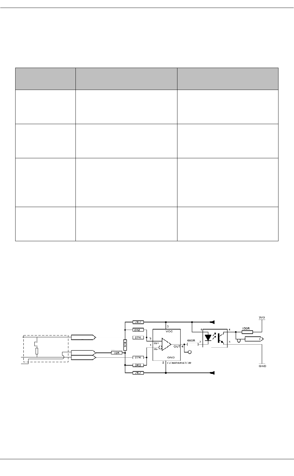
Technical reference
Page 60
6.2 Transmission intervals
The IEC61162 sentences are in general output in response to a specific event, such as initiation of a binary
message via the user interface. Certain messages are output over the ports at regular transmission intervals.
Table 11lists each sentence type and the transmission interval.
Table 11 IEC61162 transmission interval for periodic sentences
6.3 Sensor data input port
The sensor data input port schematic is shown in Figure 58. The optional 120 Ohm termination is selectable
via a jumper in the junction box and should be fitted in the ‘R’ position when long cables connecting to the data
source are required - see section 4.4.4. Each sensor data input port is isolated from other data port inputs and
from the transceivers internal power supply.
Figure 58 Input port schematic
A logical low input is defined as: A-B < -0.2V.
A logical high input is defined as: A-B > +0.2V.
The input impedance is approximately 54 kOhms without the junction box jumper fitted, and 120 Ohms with the
jumper fitted.
Output sentence
type Transmission interval Comments
VDO once a second Own vessel VDL reports. When a
report is not generated by the
transceiver a ‘dummy’ VDO is gen-
erated in its place.
ALR (inactive) once a minute An ALR sentence for each internal
alarm is output as a single block
once every minute whilst all alarms
are inactive
ALR (active) once every thirty seconds Once an alarm becomes active the
transmission interval switches to
once every thirty seconds. The
active alarm is not reported as part
of the block of inactive alarms dur-
ing this period.
ABK, ACA, LR1,
LR2, LR3, LRF,
LRI, TXT,
VDM,RTCM
Only transmitted when specifically
initiated by an external event
Input B
Input A
Input GND
Isolated
supply +
Isolated
supply -
To UART
120 Ohms
Jumper
In junction box
A
B
Data input
port
GND
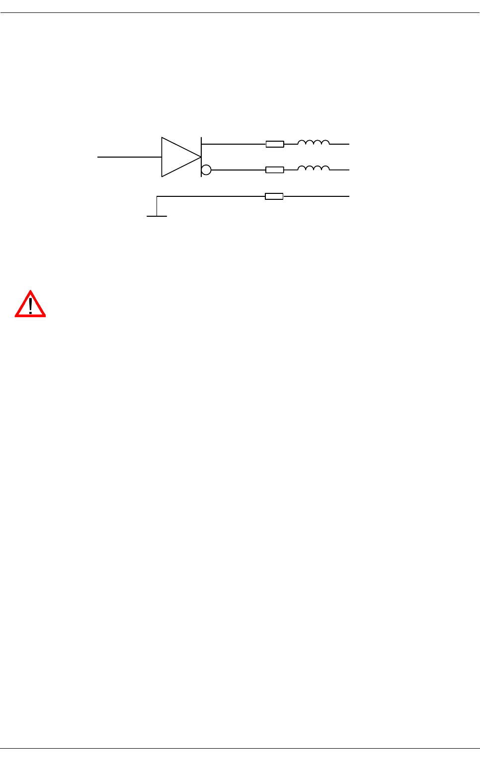
Technical reference
Page 61
6.4 Bi-directional data ports
The input circuitry of the bi-directional data ports is identical to the input circuitry for the sensor data input ports
described in the preceding section. The output circuitry consists of a differential line driver IC (Texas
Instruments AM26LV31E) and is shown in Figure 59.
Figure 59 Data output port schematic
6.5 Output drive capability of bi-directional ports
Bi-directional ports can supply an output current of up to 30mA. The output voltages are 0 (low) and 3.3V (high).
Effective load resistance should be in excess of 100 Ohms.
6.6 DGPS port
The DPGS correction port is intended for connection to a DGPS beacon receiver. The port has the same
physical characteristics as the bi-directional data ports as described in the preceding sections. If connection of
a beacon receiver is not required this port can be re-configured as an additional bi-directional port to
IEC61162-2. See section 3.16 for port configuration options.
6.7 RS232 port
The RS232 port carries IEC61162 data via RS232 and is intended for connection to a PC during installation
and service. The port can also be used to connect to PC based charting applications for display of AIS data.
6.8 Input data sentence formats
All data input is via IEC61162 / NMEA 0183 sentences. The sentences used by the AIS transceiver are
documented in the subsequent sections. The sentence structure tables describe each field in the sentence
starting from the left most field (field 1) after the sentence identifier. All sentences are terminated with the
IEC61162 checksum shown as ‘*hh’. For details of the checksum calculation please refer to IEC61162-1.
From UART
B
A
GND
100 Ohms GND
10 Ohms
10 Ohms
220 Ohms
@100MHz
220 Ohms
@100MHz
Data output port
Each bi-directional data port input is isolated from other data port inputs and from the
transceivers internal power supply. The bi-directional data port outputs are not isolated from each
other or the transceivers internal power supply. The transceivers internal power supply is fully
isolated from the external supply.

Technical reference
Page 62
6.8.1 ABM - Addressed binary and safety related message
This sentence allows external applications to transmit binary and safety messages using the AIS transceiver
via AIS messages 6 and 12.
6.8.2 ACA - AIS regional channel assignment message
This sentence is used to both enter and obtain channel management information.
!--ABM,x,x,x,xxxxxxxxx,x,x.x,s--s,x*hh<CR><LF>
Field
number
Description
1x = Total number of sentences needed to transfer the message
2x = Sentence number
3x = Sequential Message identifier
4xxxxxxxxx = The MMSI of destination AIS transceiver for the ITU-R M.1371 message
5x = AIS channel for broadcast of the radio message
6x.x = ITU-R M.1371 message ID
7s--s = Encapsulated data
8x = Number of fill-bits, 0-5
$--ACA,x,llll.ll,a,yyyyy.yy,a,llll.ll,a,yyyyy.yy,a,x,xxxx,x,xxxx,x,x,x,a,x,hhmmss.ss*hh<CR><LF>
Field
number
Description
1x = Sequence Number, 0 to 9
2llll.ll,a = Region Northeast corner latitude - N/S
3yyyyy.yy,a = Region Northeast corner longitude - E/W
4llll.ll,a = Region Southwest corner latitude - N/S
5yyyyy.yy,a = Region Southwest corner longitude - E/W
6x = Transition Zone Size
7xxxx = Channel A
8x = Channel A bandwidth
9xxxx = Channel B
10 x = Channel B bandwidth
11 x = Tx/Rx mode control
12 x = Power level control
13 a = Information source
14 x = In-Use Flag
15 hhmmss.ss = Time of “in-use” change

Technical reference
Page 63
6.8.3 ACK - Acknowledge alarm
This sentence is used to acknowledge an alarm condition reported by the transceiver.
6.8.4 AIR - AIS Interrogation request
This sentence supports ITU-R M.1371 message 15. It provides external applications with the means to initiate
requests for specific ITU-R M.1371 messages from remote AIS stations.
6.8.5 BBM -Binary broadcast message
This sentence allows generation of ITU-R M.1371 binary broadcast messages (message 8) or broadcast safety
related messages (message 14). The content of the message is defined by the application.
$--ACK,xxx,*hh<CR><LF>
Field
number
Description
1xxx = Identification number of the alarm source to be acknowledged.
$--AIR,xxxxxxxxx,x.x,x,x.x,x,xxxxxxxxx,x.x,x*hh<CR><LF>
Field
number
Description
1xxxxxxxxx = MMSI of interrogated station-1
2x.x = ITU-R M.1371 message requested from station-1
3x = Message sub-section (Reserved for future use)
4x.x = Number of second message from station-1
5x = Message sub-section (Reserved for future use)
6xxxxxxxxx = MMSI of interrogated station-2
7x.x = Number of message requested from station-2
8x = Message sub-section (Reserved for future use)
!--BBM,x,x,x,x,x.x,s--s,x*hh<CR><LF>
Field
number
Description
1x = Total number of sentences needed to transfer the message, 1 to 9
2x = Sentence number, 1 to 9
3x = Sequential message identifier, 0 to 9
4x = AIS channel for broadcast of the radio message
5x.x = ITU-R M.1371 message ID, 8 or 14
6s--s = Encapsulated data
7x = Number of fill-bits , 0 to 5
Technical reference
Page 64
6.8.6 DTM - Datum reference
Logical geodetic datum and datum offsets from a reference datum.
Possible datum and reference datum values are:
●WGS84 = W84
●WGS72 = W72
●SGS85 = S85
●PE90 = P90
●User defined =999 (only available for “Local datum”)
●IHO datum code ( „ -„- „ -„- -„- )
6.8.7 GBS - GNSS satellite fault detection
This sentence is used to support GNSS receiver autonomous integrity monitoring (RAIM). Given that a GNSS
receiver is tracking enough satellites to perform integrity checks of the positioning quality of the position
solution, a message is needed to report the output of this process to other systems to advise the system user.
With the RAIM in the GNSS receiver, the receiver can isolate faults to individual satellites and not use them in
its position and velocity calculations. Also, the GNSS receiver can still track the satellite and easily judge when
it is back within tolerance.
This sentence shall be used for reporting this RAIM information. To perform this integrity function, the GPS
receiver must have at least two observables in addition to the minimum required for navigation. Normally these
observables take the form of additional redundant satellites.
$--DTM,ccc,a,x.x,a,x.x,a, x.x,ccc*hh<CR><LF>
Field
number
Description
1ccc = Local datum
2a = Local datum subdivision code - NOT USED
3x.x, a = Lat offset, min, N/S - NOT USED
5x.x,a = Longitude offset, min, E/W - NOT USED
7x.x = Altitude offset, (meter) - NOT USED
8ccc = Reference datum
$--GBS, hhmmss.ss, x.x, x.x, x.x, xx, x.x, x.x, x.x *hh <CR><LF>
Field
number
Description
1hhmmss.ss UTC time of the GGA or GNS fix associated with this sentence
2x.x Expected error in latitude
3x.x Expected error in longitude
4x.x Expected error in altitude - NOT USED
5xx ID number of most likely failed satellite - NOT USED

Technical reference
Page 65
6.8.8 GGA - Global positioning system (GPS) fix data
This sentence provides time, position and fix related data from a GPS receiver.
6.8.9 GLL - Geographic position, latitude and longitude
This sentence provides the latitude and longitude for vessel position along with fix time and status.
6x.x Probability of missed detection for most likely failed satellite - NOT USED
7x.x Estimate of bias on most likely failed satellite - NOT USED
8x.x Standard deviation of bias estimate - NOT USED
$--GGA, hhmmss.ss, llll.ll, a, yyyyy.yy, a, x, xx, x.x, x.x, M, x.x, M, x.x, xxxx*hh<CR><LF>
Field
number
Description
1hhmmss.ss UTC time of position fix
2llll.ll, a Latitude N/S
3yyyyy.yy, a Longitude E/W
4 x GPS quality indicator
5xx No. of satellites in use, 00-12 - NOT USED
6x.x Horizontal dilution of precision - NOT USED
7x.x Antenna altitude above/below mean sea level (geoid) - NOT USED
8 M Units of antenna altitude, m - NOT USED
9x.x Geoidal separation - NOT USED
10 MUnits of geoidal separation, m - NOT USED
11 x.x Age of diff. GPS data - NOT USED
12 xxxx Differential reference station ID 0000-1023 - NOT USED
$--GLL, llll.ll, a, yyyyy.yy, a, hhmmss.ss, A, a *hh<CR><LF>
Field
number
Description
1 llll.ll, a Latitude, N/S
2yyyyy.yy, a Longitude , E/W
$--GBS, hhmmss.ss, x.x, x.x, x.x, xx, x.x, x.x, x.x *hh <CR><LF>

Technical reference
Page 66
6.8.10 GNS - GNSS fix data
This sentence provides fix data for a single or combined satellite navigation system. The sentence provides
data for GPS, GLONASS and possible future satellite systems and combinations thereof.
6.8.11 HDT - Heading, true
Actual vessel heading in degrees produced by a true heading system or device.
3hhmmss.ss Time of position (UTC)
4 A Status: A = data valid V = data invalid
5 a Mode indicator:
A = Autonomous
D = Differential
E = Estimated (dead reckoning)
M = Manual input
S = Simulator
N = Data not valid
$-- GNS, hhmmss.ss, llll.ll, a, yyyyy.yy, a, c--c,xx,x.x,x.x,x.x,x.x,x.x *hh<CR><LF>
Field
number
Description
1hhmmss.ss Time of position (UTC)
2llll.ll, a Latitude N/S
3yyyyy.yy, a Longitude E/W
4c--c Mode indicator
5xx Number of satellites in use, 00-99 - NOT USED
6x.x Horizontal dilution of precision (HDOP) - NOT USED
7x.x Antenna altitude, m, above mean-sea-level - NOT USED
8x.x Geoidal separation, m - NOT USED
9x.x Age of differential data - NOT USED
10 x.x Differential reference station ID - NOT USED
$--HDT, x.x, T*hh<CR><LF>
Field
number
Description
1x.x, T Heading, degrees true
$--GLL, llll.ll, a, yyyyy.yy, a, hhmmss.ss, A, a *hh<CR><LF>

Technical reference
Page 67
6.8.12 LRF - Long range function
This sentence is used in long range interrogation requests and interrogation replies.
6.8.13 LRI - Long range interrogation
The long-range interrogation of the AIS is accomplished through the use of two sentences. The pair of
interrogation sentences, a LRI-sentence followed by a LRF-sentence, provides the information needed by an
AIS to determine if it must construct and provide the reply sentences (LRF, LR1, LR2, and LR3).
$--LRF,x,xxxxxxxxx,c--c,c--c,c--c*hh<CR><LF>
Field
number
Description
1 x Sequence number , 0 to 9
2xxxxxxxxx MMSI of requestor
3c--c Name of requestor, 1 to 20 character string
4c--c Function request, 1 to 26 characters from:
A = Ship’s name, call sign and IMO number
B = Date and time of message composition
C = Position
E = Course over ground
F = Speed over ground
I = Destination and ETA
O = Draught
P = Ship / Cargo type
U = Ship’s length, breadth and type
W = Persons on board
5c--c Function reply status:
2 = Information available and provided in the following LR1, LR2, or LR3 sen-
tence
3 = Information not available from AIS transceiver
4 = Information is available but not provided (i.e. restricted access determined
by ship's master)
$--LRI,x,a,xxxxxxxxx,xxxxxxxxx,llll.ll,a,yyyyy.yy,a,llll.ll,a,yyyyy.yy,a*hh<CR><LF>
Field
number
Description
1 x Sequence number, 0-9
2 a Control Flag
3xxxxxxxxx MMSI of "requestor"
4xxxxxxxxx MMSI of “destination”
5llll.ll,a Latitude - N/S
6yyyyy.yy,a Longitude - E/W (north-east co-ordinate)
7llll.ll,a Latitude - N/S
8yyyyy.yy,a Longitude - E/W (south-west co-ordinate)

Technical reference
Page 68
6.8.14 RMC - Recommended minimum specific GNSS data
Time, date, position, course and speed information provided by a GNSS receiver. All data fields should be
provided and null fields only used when data is temporarily unavailable.
6.8.15 ROT - Rate of turn
This sentence provides rate of turn and direction of turn information.
6.8.16 SSD - Station static data
This sentence is used to enter static parameters into the ship’s AIS transceiver. The parameters in this
message provide contents for various ITU-R M.1371 messages.
$--RMC, hhmmss.ss, A, llll.ll,a, yyyyy.yy, a, x.x, x.x, xxxxxx, x.x,a, a*hh<CR><LF>
Field
number
Description
1hhmmss.ss Time of position fix (UTC)
2 A Status: A = data valid V = navigation receiver warning
3llll.ll, a Latitude, N/S
4yyyyy.yy, a Longitude, E/W
5x.x Speed over ground, knots
6x.x Course over ground, degrees true
7xxxxxx Date: dd/mm/yy - NOT USED
8x.x, a Magnetic variation, degrees, E/W - NOT USED
10 aMode indicator:
A = Autonomous mode
D = Differential mode
E = Estimated (dead reckoning) mode
M = Manual input mode
S = Simulator mode
N = Data not valid
$--ROT, x.x, A*hh<CR><LF>
Field
number
Description
1x.x Rate of turn, °/min, "-" = bow turns to port
2 A Status: A = data valid, V = data invalid
$--SSD,c--c,c--c,xxx,xxx,xx,xx,c,aa*hh<CR><LF>
Field
number
Description
1c--c Ship's Call Sign, 1 to 7 characters
2c--c Ship's Name, 1 to 20 characters
3xxx Pos. ref., "A," distance from bow, 0 to 511 metres

Technical reference
Page 69
6.8.17 VBW - Dual ground / water speed
This sentence conveys both water and ground referenced speed data.
6.8.18 VSD - Voyage static data
This sentence is used to enter information about the ship’s voyage.
4xxx Pos. ref., "B," distance from stern, 0 to 511 metres
5xx Pos. ref., "C," distance from port beam, 0 to 63 metres
6xx Pos. ref., "D," distance from starboard beam, 0 to 63 metres
7 c DTE indicator flag
8aa Source identifier
$--VBW, x.x, x.x, A, x.x, x.x, A, x.x, A, x.x, A*hh<CR><LF>
Field
number
Description
1x.x Longitudinal water speed, knots - NOT USED
2x.x Transverse water speed, knots - NOT USED
3 A Status: water speed, (A = data valid, V = data invalid) - NOT USED
4x.x Longitudinal ground speed, knots
5x.x Transverse ground speed, knots
6 A Status, ground speed, (A = data valid, V = data invalid)
7x.x Stern transverse water speed, knots - NOT USED
8 A Status: stern water speed, (A = data valid, V = data invalid) - NOT USED
9x.x Stern transverse ground speed, knots - NOT USED
10 AStatus: stern ground speed, (A = data valid, V = data invalid) - NOT USED
$--VSD,x.x,x.x,x.x,c--c,hhmmss.ss,xx,xx,x.x,x.x*hh<CR><LF>
Field
number
Description
1x.x Type of ship and cargo category, 0 to 255
2x.x Maximum present static draught, 0 to 25.5 metre
3x.x Persons on-board, 0 to 8191
4c--c Destination, 1-20 characters
5hhmmss.ss Estimated time of arrival at destination (UTC)
6xx Estimated day of arrival at destination, 00 to 31 (UTC)
$--SSD,c--c,c--c,xxx,xxx,xx,xx,c,aa*hh<CR><LF>

Technical reference
Page 70
6.8.19 VTG - Course over ground and ground speed
The vessels actual course and speed relative to ground.
6.9 Output data sentence formats
All data output is via IEC61162 / NMEA 0183 sentences. The sentences used by the AIS transceiver are
documented in the subsequent sections. The sentence structure tables describe each field in the sentence
starting from the left most field (field 1) after the sentence identifier. All sentences are terminated with the
IEC61162 checksum shown as ‘*hh’. For details of the checksum calculation please refer to IEC61162-1.
All sentences start with the delimiter “$” or “!” followed by the talker equipment type identifier. The identifier for
AIS is “AI”, e.g., “AIABK”.
6.9.1 ABK - Addressed and binary broadcast acknowledgement
The ABK sentence is generated when a transaction, initiated by reception of an ABM, AIR, or BBM sentence
is completed or terminated.
7xx Estimated month of arrival at destination, 00 to 12 (UTC)
8x.x Navigational status, 0 to 15
9x.x Regional application flags, 0 to 15
$--VTG, x.x, T, x.x, M, x.x, N, x.x, K,a*hh<CR><LF>
Field
number
Description
1x.x, T Course over ground, degrees true
2x.x, M Course over ground, degrees magnetic - NOT USED
3x.x, N Speed over ground, knots
4x.x, K Speed over ground, km/h
5 a Mode indicator:
A = Autonomous mode
D = Differential mode
E = Estimated (dead reckoning) mode
M = Manual input mode
S = Simulator mode
N = Data not valid
$--ABK,xxxxxxxxx,a,x.x,x,x*hh<CR><LF>
Field
number
Description
1xxxxxxxxx MMSI of the addressed destination AIS transceiver
2 a AIS channel of reception
3x.x ITU-R M.1371 message ID
4 x Message Sequence Number
5 x Type of acknowledgement
$--VSD,x.x,x.x,x.x,c--c,hhmmss.ss,xx,xx,x.x,x.x*hh<CR><LF>

Technical reference
Page 71
6.9.2 ACA - AIS Channel assignment message
See section 6.8.2.
6.9.3 ALR - Set alarm state
This sentence is used to indicate local alarm conditions and status along with alarm acknowledgement status.
6.9.4 LRF - AIS long range function
See section 6.8.12.
6.9.5 LR1 - Long range reply with destination for function request ‘A’
The LR1 sentence identifies the destination for the reply and contains information requested by the ‘A’ function
character.
6.9.6 LR2 - Long range reply for function requests ‘B’, ‘C’, ‘E’ and ‘F’
The LR2 sentence contains the information requested by the B, C, E and F function characters.
$--ALR,hhmmss.ss,xxx,A, A,c--c*hh<CR><LF>
Field
number
Description
1hhmmss.ss Time of alarm condition change, UTC
2xxx Local alarm number (identifier)
3 A Alarm condition (A = threshold exceeded, V = not exceeded)
4 A Alarm's acknowledge state, A = acknowledged , V = unacknowledged
5c--c Alarm's description text
$--LR1,x,xxxxxxxxx,xxxxxxxxx,c--c,c--c,xxxxxxxxx*hh<CR><LF>
Field
number
Description
1 x Sequence Number, 0 to 9
2xxxxxxxxx MMSI of responder
3xxxxxxxxx MMSI of requestor (reply destination)
4c--c Ship's name, 1 to 20 characters
5c--c Call Sign, 1 to 7 characters
6xxxxxxxxx IMO Number, 9-digit number
$--LR2,x,xxxxxxxxx,xxxxxxxx,hhmmss.ss,llll.ll,a,yyyyy.yy,a,x.x,T,x.x,N*hh<CR><LF>
Field
number
Description
1 x Sequence Number, 0 to 9
2xxxxxxxxx MMSI of responder
3xxxxxxxxx Date: ddmmyyyy, 8 digits

Technical reference
Page 72
6.9.7 LR3 - Long range reply for function requests ‘I’, ‘O’, ‘P’, ‘U’, and ‘W’
The LR3 sentence contains the information requested by the I, O, P, U and W function characters.
6.9.8 TXT - Text transmission
For the transmission of short text messages from the AIS equipment. These messages relate to the status of
the equipment.
4hhmmss.ss Time of position, UTC
5llll.ll,a Latitude, N/S
6yyyyy.yy,a Longitude, E/W
7x.x,T Course over ground, degrees True
8x.x,N Speed over ground, knots
$--LR3,x,xxxxxxxxx,c--c,xxxxxx,hhmmss.ss,x.x,cc,x.x,x.x,x.x,x.x*hh<CR><LF>
Field
number
Description
1 x Sequence Number, 0 to 9
2xxxxxxxxx MMSI of "responder"
3c--c Voyage destination, 1 to 20 characters
4xxxxxx ETA Date: ddmmyy
5hhmmss.ss ETA Time, value to nearest second
6x.x Draught, value to 0,1 metre
7cc Ship/cargo (ITU-R M.1371, Table 18)
8x.x Ship length, value to nearest metre
9x.x Ship breadth, value to nearest metre
10 x.x Ship type
11 x.x Persons, 0 to 8191
$--TXT,xx,xx,xx,c--c*hh<CR><LF>
Field
number
Description
1xx Total number of messages, 01 to 99
2xx Message number, 01 to 99
3xx Text identifier, 01-99
4c--c Text message, ASCII, up to 61 characters
$--LR2,x,xxxxxxxxx,xxxxxxxx,hhmmss.ss,llll.ll,a,yyyyy.yy,a,x.x,T,x.x,N*hh<CR><LF>

Technical reference
Page 73
6.9.9 VDM - VHF data link message
This sentence is used to transfer the contents of a received AIS message (as defined in ITU-R M.1371) as
received on the VHF Data Link (VDL) using 6 bit ASCII data encapsulation.
6.9.10 VDO - VHF data link own vessel message
This sentence is used to provide the information assembled for broadcast by the AIS transceiver. It uses 6 bit
ASCII data encapsulation.
!--VDM,x,x,x,a,s--s,x*hh<CR><LF>
Field
number
Description
1 x Total number of sentences needed to transfer the message, 1 to 9
2 x Sentence number, 1 to 9
3 x Sequential message identifier, 0 to 9
4 a AIS Channel, "A" or "B"
5s--s Encapsulated ITU-R M.1371 radio message
6 x Number of fill-bits, 0 to 5
!--VDO,x,x,x,a,s--s,x*hh<CR><LF>
Field
number
Description
1 x Total number of sentences needed to transfer the message, 1 to 9
2 x Sentence number, 1 to 9
3 x Sequential message identifier, 0 to 9
4 a AIS Channel, "A" or "B"
5s--s Encapsulated ITU-R M.1371 radio message
6 x Number of fill-bits, 0 to 5
Drawings
Page 74
7 Drawings
7.1 AIS transceiver overall dimensions
7.2 Junction box overall dimensions
105 mm
85 mm
195 mm
172 mm
112 mm
157 mm
178 mm
52 mm
76 mm
165 mm
58 mm
Drawings
Page 75
7.3 Dash mount bracket fixing holes (drill drawing) (not to scale)
7.4 GPS antenna drawing (not to scale)
120.0mm
40.0mm
Drill for screw size No. 8 (4-PL)
Tap drill size No. 29 (3mm drill is sufficient)
108mm
21.3mm
10m RG58 cable
TNC (male)

Annex A - ERI Ship types
Page 76
8 Annex A - ERI Ship types
The table below should be used to convert the UN ERI Ship type (used in Inland AIS) to the IMO ship type used
in standard AIS operation. ERI ship types are transmitted in Inland AIS message type 10 whereas the ITU
vessel type is transmitted in AIS message 5.
ERI Code (Inland AIS) ITU AIS
Vessel type
code
Full
code
UShip Name (EN) Vorschlag Via 1st
digit
2nd
digit
8000 No Vessel, type unknown Unbekannter Schiffstyp 9 9
8010 V Motor Freighter Motorgüterschiff (MGS) 7 9
8020 V Motor tanker Motortankschiff (MTS) 8 9
8021 V Motor tanker, liquid cargo, type N Motortankschiff, Flüssigfracht,
Typ N
80
8022 V Motor tanker, liquid cargo, type C Motortankschiff, Flüssigfracht,
Typ C
80
8023 V Motor tanker, dry cargo as if liquid (e.g
cement)
Motortankschiff, Trockenfracht 8 9
8030 V Container Vessel Containerschiff 7 9
8040 V Gas tanker Gas-Tankschiff 8 0
8050 C Motor freighter, tug Motorzugschiff 7 9
8060 C Motor tanker, tug Motortankzugschiff 8 9
8070 C Motor freighter with one or more ships
alongside
Gekoppelte Fahrzeuge, MGS 7 9
8080 C Motor freighter with tanker Gekoppelte Fahrzeuge, mind.
1 MTS
89
8090 C Motor freighter pushing one or more
freighters
Schubverband, MGS 7 9
8100 C Motor freighter pushing at least one
tank-ship
Schubverband, mind. 1 TSL 8 9
8110 No Tug, freighter Schlepp-Güterschiff 7 9
8120 No Tug, tanker Schlepp-Tankschiff 8 9
8130 C Tug freighter, coupled Gekoppelte
Schlepp-Güterschiffe
31
8140 C Tug, freighter/tanker, coupled Gekoppeltes Schlepp-Schiff,
min. 1 Schl.TS
31
8150 V Freightbarge Schubleichter (SL) 9 9

Annex A - ERI Ship types
Page 77
8160 V Tankbarge Tankschubleichter (TSL) 9 9
8161 V Tankbarge, liquid cargo, type N Tankschubleichter,
Flüssigfracht Typ N
90
8162 V Tankbarge, liquid cargo, type C Tankschubleichter,
Flüssigfracht, Typ C
90
6163 V Tankbarge, dry cargo as if liquid (e.g
cement)
Tankschubleichter,
Trockenfracht
99
8170 V Freightbarge with containers Tankschubleichter mit
Containern
89
8180 V Tankbarge, gas Tankschubleichter für Gas 9 0
8210 C Pushtow, one cargo barge Motorschubschiff mit 1 SL 7 9
8220 C Pushtow, two cargo barges Motorschubschiff mit 2 SL 7 9
8230 C Pushtow, three cargo barges Motorschubschiff mit 3 SL 7 9
8240 C Pushtow, four cargo barges Motorschubschiff mit 4 SL 7 9
8250 C Pushtow, five cargo barges Motorschubschiff mit 5 SL 7 9
8260 C Pushtow, six cargo barges Motorschubschiff mit 6 SL 7 9
8270 C Pushtow, seven cargo barges Motorschubschiff mit 7 SL 7 9
8280 C Pushtow, eight cargo barges Motorschubschiff mit 8 SL 7 9
8290 C Pushtow, nine or more barges Motorschubschiff mit mehr als
8 SL
79
8310 C Pushtow, one tank/gas barge Motorschubschiff mit 1 TSL 8 0
8320 C Pushtow, two barges at least one tanker
or gas barge
Motorschubschiff mit 2 SL –
min.1 TSL
80
8330
C Pushtow, three barges at least one
tanker or gas barge
Motorschubschiff mit 3 SL –
min.1 TSL
80
8340 C Pushtow, four barges at least one tanker
or gas barge
Motorschubschiff mit 4 SL –
min.1 TSL
80
8350 C Pushtow, five barges at least one tanker
or gas barge
Motorschubschiff mit 5 SL –
min. 1 TSL
80
8360 C Pushtow, six barges at least one tanker
or gas barge
Motorschubschiff mit 6 SL –
min. 1 TSL
80
8370 C Pushtow, seven barges at least one
tanker or gas barge
Motorschubschiff mit 7 SL –
min. 1 TSL
80
8380 C Pushtow, eight barges at least one
tanker or gas barge
Motorschubschiff mit 8 SL –
min.1 TSL
80
8390 C Pushtow, nine or more barges at least
one tanker or gas barge
Motorschubschiff >8 SL –
min.1 TSL
80

Annex A - ERI Ship types
Page 78
8400 V Tug, single Motorzugschiff 5 2
8410 No Tug, one or more tows Motorzugschiff 3 1
8420 C Tug, assisting a vessel or linked
combination
Motorzugschiff assistierend 3 1
8430 V Pushboat, single Motorschubschiff 9 9
8440 V Passenger ship, ferry, cruise ship, red
cross ship
Motorfahrgastschiff 6 9
8441 V Ferry Fähre 6 9
8442 V Red cross ship Krankentransport 5 8
8443 V Cruise ship Kabinenschiff 6 9
8444 V Passenger ship without accomodation Ausflugsschiff 6 9
8450 V Service vessel, police patrol, port
service
Bundes-, Einsatzfahrzeug 9 9
8460 V Vessel, work maintainance craft, floating
derrick, cable- ship, buoy-ship, dredge
Arbeitsfahrzeug 3 3
8470 C Object, towed, not otherwise specified Geschlepptes Objekt 9 9
8480 V Fishing boat Fischerboot 3 0
8490 V Bunkership Bunkerboot 9 9
8500 V Barge, tanker, chemical Tankschubleichter, chemische
Stoffe
80
8510 C Object, not otherwise specified Objekt, nicht näher bezeichnet 9 9
1500 V General cargo Vessel maritime Frachtschiff (See) 7 9
1510 V Unit carrier maritime Containerschiff (See) 7 9
1520 V Bulk carrier maritime Massengutschiff (See) 7 9
1530 V Tanker Tankschiff (Kein Gas) (See) 8 0
1540 V Liquified gas tanker Seegehendes Gas-Tankschiff
(See)
80
1850 V Pleasure craft, longer than 20 metres Sportboot > 20 m (See) 3 7
1900 V Fast ship Schnelles Schiff 4 9
1910 V Hydrofoil Tragflügelboot 4 9
Installation record
Page 79
9 Installation record
The following installation record should be completed and retained on board the vessel once the AIS
transceiver has been installed and commissioned.
Vessel details
Vessel name
Flag state
IMO number MMSI number
Owner Radio call sign
Type of vessel Gross registered tonnage
Length (m) Beam (m)
AIS transceiver serial number
(see underside of transceiver or packaging
label)
Junction box serial number (see label on junc-
tion box)
Installation password (if changed from default)
Transceiver software version number
UI software version number
GPS / GNSS antenna locations
Internal GPS antenna location (all dimensions in meters, refer to the diagram below)
A= B= C= D=
External GNSS antenna location (all dimensions in meters, refer to the diagram below)
A= B= C= D=
Ref A
Antenna
Ref A + Ref B = Length in metres Ref C + Ref D = Beam in metres
Ref B
Stern Bow
Ref C
Ref D

Installation record
Page 80
The following drawings should be provided and attached to this installation record:
●Antenna layout for VHF and GPS antennas
●AIS arrangement drawing
●Block diagram showing interconnection of equipment
Maintenance record
Connected equipment type (where applicable note equipment model and AIS data port in each case)
(D)GPS receiver
Gyro compass
ROT indicator
Speed log
ECDIS
Radar
Other equipment
Power supply
Modification record number Details (enter details of modifications to the transceiver including software
updates)
1
2
3
4
5
6
8
9
10

Installation record
Page 81
Installer detail
Installed by (name)
Installation company name
Date of installation
Vessel location at installation
Signature

Installation record
Page 82

Warranty
Page 83
10 Warranty
What this warranty covers
The Manufacturer of this Product warrants to the Buyer that the Product will be free from defects under normal
use (“Defects”) for a period of five (5) years from the date that the Product was purchased ("Warranty
Period").
What this warranty does not cover
The Limited Warranty does not apply to normal wear and tear, does not apply when the Product is opened or
repaired by someone not authorised by the Manufacturer and does not cover repair or replacement of any
element of the Product damaged by misuse, moisture, exposure to heat, abuse or failure to comply with the
instructions supplied with the Product.
How to make a warranty claim
In order to make a claim of a Defect, you must contact the Manufacturer during the Warranty Period to explain
the Defect and to obtain an RMA number (Return Materials Authorisation) if necessary. You must return the
Product during the Warranty Period (at your own expense), along with an explanation of the Defect, to the
address provided to you by the Manufacturer. If the Warranty claim is deemed to be valid the Manufacturer will
reimburse to you the cost of shipping and return the Product to you after repair.
Your legal rights
This Limited Warranty does not affect any legal rights under applicable national legislation governing the sale
of consumer goods. This Limited Warranty cannot be transferred to any other person.
Limitation of liability
The Manufacturer and its suppliers shall not be liable to you or to any third party for any damages either
direct, indirect, consequential or otherwise including but not limited to damages for the inability to use the
equipment arising out of the use of or inability to use the Product.
The entire liability of the Manufacturer and any of its suppliers shall be limited to the amount actually paid by
you for the Product. The provisions of this Limited Warranty are in lieu of any other warranty, whether
expressed or implied, written or oral. The Manufacturer and its suppliers shall not be liable for any incidental,
indirect, consequential or special (including punitive or multiple) damages, loss of profit, business, contracts,
opportunity, goodwill or other similar loss.

Warranty
Page 84

201-0052:V1